Embed Size (px)
Citation preview

ID3000operating
manual
997-505-000-3, Issue 3 October 2007
ID3000 Series Operating Manual
Co
nte
nts
i 997-505-000-3, Issue 3October 2007
Quick Contents Reference bySection
ID3000 Series Operating ManualC
on
ten
ts
ii997-505-000-3, Issue 3October 2007
Contents1 Introduction 1
1.1 Associated Documents 1
1.2 Cleaning 1
2 Panel Controls and Indicators 2
2.1 Main Panel 2
2.2 Zone LED Panels 5
3 Automatic Alarms - What to Do 6
3.1 Fire Alarms 7
3.2 Pre-alarms 8
3.3 Fault Alarms 9
4 How To: 10
4.1 Evacuate (and End Delays) 10
4.2 Mute Buzzer 11
4.3 Silence/Resound Sounders 12
4.4 Reset the Panel 13
4.5 Disable/Enable Devices and Zones(Quick Method) 14
4.5.1 From Fire Tab 14
4.5.2 From Pre-alarm Tab 15
4.5.3 From Disable Tab 15
4.6 Discontinue a Walk Test (Quick Method) 16
4.7 Select Day or Night Mode 17
4.8 Disable a Fire Output 17
4.9 Using Other Panel Controls 17
5 The Display - Tabs, Events andMenus 18
5.1 Introduction 18
5.1.1 Status:NORMAL 18
5.1.2 Tabs 18
5.1.3 Events 18
5.1.4 Menus 18
5.2 Tabs 19
5.3 Event Displays 20
5.3.1 Extinguishing System Display 20
5.3.2 Fire Alarm Event Display 22
ID3000 Series Operating Manual
Co
nte
nts
iii 997-505-000-3, Issue 3October 2007
5.3.3 Pre-alarm Event Display 23
5.3.4 Technical Alarm Display 23
5.3.5 Fault Event Display 24
5.3.6 Disable Event Display 25
5.3.7 Test Event Display 26
5.3.8 Evacuate Event Display 27
5.3.9 Auxiliary Event Display 27
5.4 Menu Displays 28
5.4.1 To Display the User Menu 28
5.4.2 To Navigate Through the Menus 29
5.4.3 Menu Structure 30
6 Test Menu 31
6.1 Introduction 31
6.1.1 Indications 31
6.2 Zone Walk Test 32
6.3 Control Output Tests 33
6.4 Lamp Test 34
6.4.1 Lamps Test in Sequence 34
6.4.2 All Lamps Lit 35
6.5 Sensor Automatic Test 36
6.6 Replace VIEW Sensor 36
7 Disable/Enable Menu 37
7.1 Introduction 37
7.1.1 Indications 37
7.2 Disable/Enable Inputs 38
7.2.1 Disable All Input Devices 38
7.2.2 Disable All Sensors 39
7.2.7 Enable All Input Devices 39
7.3 Disable/Enable Outputs 40
7.3.1 Disable/Enable All Sounders 40
7.3.2 Disable/Enable All Control Outputs 41
7.4 Individual Device 42
7.4.1 Sensor 42
7.4.2 Module 43
7.4.3 Sounder/Relay Circuit 43
7.4.4 Virtual Points 44
7.5 Delayed Sounders Mode 44
7.6 Network Disable and Enable 45
7.6.1 Input Zone 45
ID3000 Series Operating ManualC
on
ten
ts
iv997-505-000-3, Issue 3October 2007
7.6.2 Device 46
7.7 Disable/Enable via Remote Switch 47
7.8 Time-of-Day Control and Override 47
8 Log/Display/Print Menu 48
8.1 Introduction 48
8.2 Log/Display Device Data 49
8.2.1 Analog Graphical Display 51
8.3 Print Current Device Data 53
8.4 Display/Re-Print Event Log 54
8.5 Printer Control Modes 55
8.5.1 Mains Failure 55
9 Setting the Clock 56
10 Other User Menu Options 57
10.1 Alarm Count 57
10.2 Enter Level 3 Passcode/Configuration 57
10.3 Set Language 57
11 Non-latched Input Operation 58
Appendix 1 - Log Book A1 - 1

ID3000 Series Operating Manual
Intr
od
uct
ion
1 997-505-000-3, Issue 3October 2007
1 Introduction
This manual contains operating instructions forthe ID3000 Series of Intelligent Fire DetectionPanels. Users of this manual are assumed tobe working with a panel that has already beeninstalled and configured appropriately for thearea under its supervision.
The ID3000 Series panel always has a mainchassis, which includes all of the panel controlsand indicators except for zone LEDs. Thepanel may also have up to two optionalextension chassis, each of which may housezone LEDs for either 64 or 128 zones (a panelcan have a maximum of 255 zones). All thecontrol and operation functions described inthis manual can be carried out using thepushbuttons on the front of the main chassis.
In some installations, panels may beconnected together in a network of up to eightpanels plus repeaters making a total of up to32 stations.
ID3000 Series panels may be connected toup to eight loops of addressable analoguesensors and modules. Each loop has thecapacity for up to 99 analogue sensors plusup to 99 modules.
1.1 Associated Documents
This manual does not cover details on theinstallation or configuration of ID3000 Seriespanels. For information on these topics, referto the ID3000 Series Installation andCommissioning Manual (997-274-XXX) andthe ID3000 Series Panel Configuration Manual(997-506-XXX) respectively.
Panel software upgrade procedures and panelsoftware compatibility issues are described inthe ID3000 Series Panel Configuration Manual(997-506-XXX).
Note: ‘XXX’ is the country code for the manual(000 for the UK).
1.2 Cleaning
The panel case may be cleaned periodicallyby wiping with a soft, damp lint-free cloth. Donot use any solvents.
Illustration shows a panel with two extension chassis,one with 64 zone LEDs and a printer, and the otherblank.

ID3000 Series Operating ManualP
anel
Co
ntr
ols
an
d In
dic
ato
rs
2997-505-000-3, Issue 3October 2007
2 Panel Controls and Indicators
2.1 Main Panel
This section provides an overview of the userinterface controls and indicators, andreferences the section(s) of this manual thatprovide more detailed information.
PRIMARY INDICATOR
LCD graphics display - refer to Section 5.
PUSHBUTTONS
Silences the panel internal buzzer, and acceptsan alarm. Refer to Section 4.2.
If DAY MODE is configured, introduces asecond stage delay if an alarm occurs whileDAY MODE is active. Refer to Section 4.7.
If any delays are active, first operation cancelsthe delays, second operation sounds allsounders so-configured. If no delays areactive, sounds all sounder so-configured.Refer to Section 4.1.
Stops and restarts the sounders. Refer toSection 4.3.
Restores normal operating status when allalarm conditions have been removed. Referto Section 4.4.
MUTEBUZZER
EXTENDDELAY
END DELAY/EVACUATE
SILENCE/RESOUND
RESET
DAY MODEFIRE O/PDISABLE
CHANGETABS
ZONES INALARM
0
2
5
8
3
6
9
1
4
7
FIRE O/P ACTIVEFIRE O/P ACTIVE
PRE-ALARMPRE-ALARM
SYSTEM FAULTSYSTEM FAULT
SOUNDER FAULT/DISABLED
FIRE O/P FAULT/DISABLEDFIRE O/P FAULT/DISABLED
FIRE
FAULT
DAY MODEDAY MODE
DELAYS ACTIVEDELAYS ACTIVE
TECHNICAL ALARMTECHNICAL ALARM
DISABLEMENTDISABLEMENT
TEST
POWER
���������� ���������������������������

ID3000 Series Operating Manual
Pan
el C
on
tro
ls a
nd
Ind
icat
ors
3 997-505-000-3, Issue 3October 2007
Toggles between day and night modes, if theyare configured. Refer to Section 4.7.
The Fire relay output (and the Fire Output, ifsounder circuit 1 is configured as such) isdisabled. Refer to Section 4.8.
Spare - Not used.
Scrolls through the tabbed displays. Also usedto display the User Menu when the panel statusis Normal. Refer to Sections 5.2 and 5.3.
Displays fire alarm information. If there is morethan one zone in fire event, scrolls throughthese zones. Refer to Section 5.2 and 5.3.
KEYPAD
Used to move around the LCD menus. Press
and hold to advance the printer paper(maximum of 20 lines are advanced for asingle press of this pushbutton).
Used to select quick methods of dis/enablement (Section 4.5) and walk testcancellation (Section 4.6), to navigate throughthe menus (Section 5.4.2) and to control theevent log display (Section 8.4). Also usedduring configuration (refer to the PanelConfiguration Manual 997-506-XXX).
Used to select items and enter data on LCD.
Used to accept an item or state on the LCD.
Used to cancel an item or state on the LCD.
Setting the keyswitch to the right has the sameeffect as entering an access 2 passcode. Setit to the centre to de-select access level 2.
ID3000 Series Operating ManualP
anel
Co
ntr
ols
an
d In
dic
ato
rs
4997-505-000-3, Issue 3October 2007
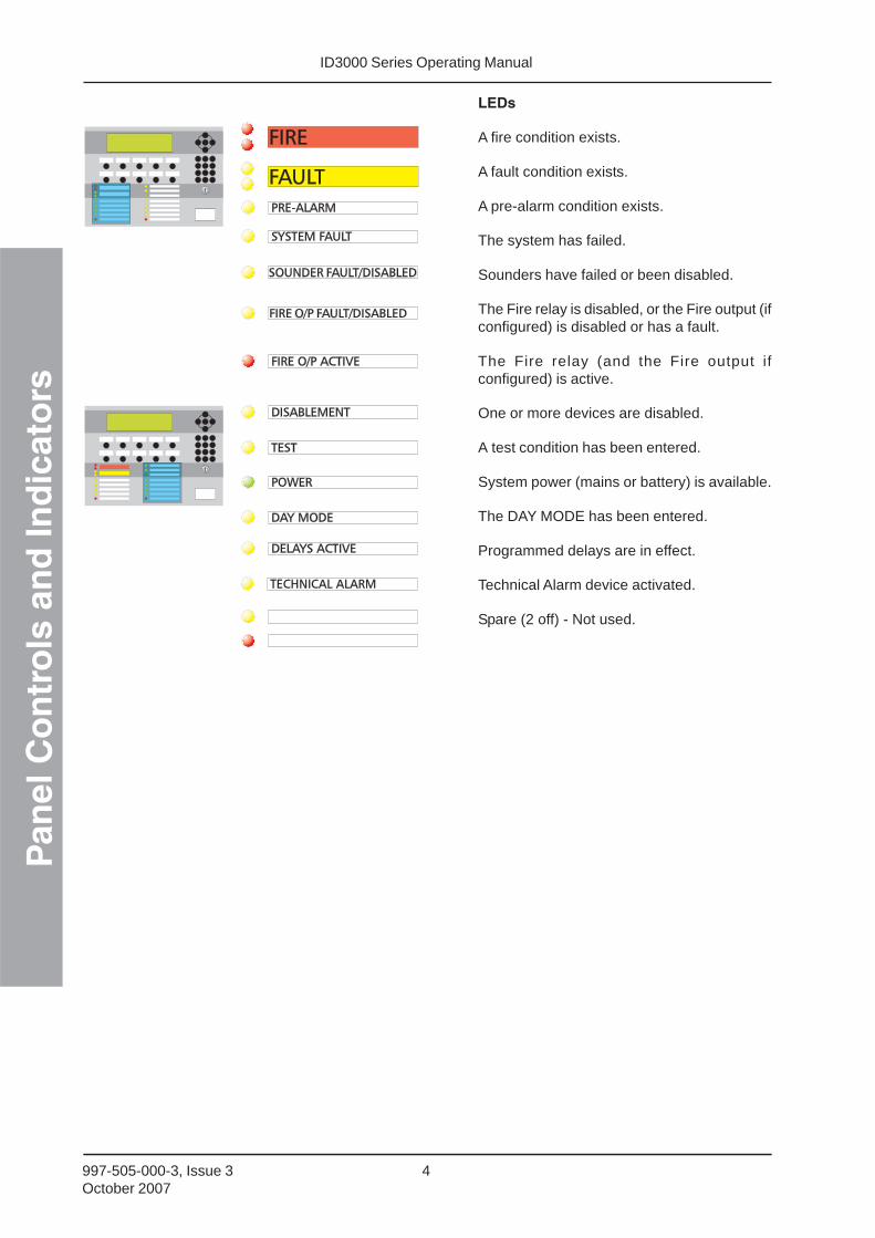
LEDs
A fire condition exists.
A fault condition exists.
A pre-alarm condition exists.
The system has failed.
Sounders have failed or been disabled.
The Fire relay is disabled, or the Fire output (ifconfigured) is disabled or has a fault.
The Fire relay (and the Fire output ifconfigured) is active.
One or more devices are disabled.
A test condition has been entered.
System power (mains or battery) is available.
The DAY MODE has been entered.
Programmed delays are in effect.
Technical Alarm device activated.
Spare (2 off) - Not used.
TECHNICAL ALARMTECHNICAL ALARM

ID3000 Series Operating Manual
Pan
el C
on
tro
ls a
nd
Ind
icat
ors
5 997-505-000-3, Issue 3October 2007
2.2 Zone LED Panels
Two configurations of optional zone LEDchassis may be fitted, each with up to twochassis, as follows:
a. 64 zone LEDs per chassis, i.e. 128 zoneLEDs in total. This configuration allows aprinter to be fitted.
b. 128 zone LEDs per chassis, i.e. 256 zoneLEDs in total (maximum 255 zones).
ZONE FIRE LEDs indicate which zones are in a firecondition.
ZONE FAULT/DISABLE/TEST LEDs indicate whichzones are in fault, disablement or test conditions.
64 zone configuration:ZONE LEDs 1-64(chassis 1).
ZONE LEDs 65-128(chassis 2).
128 zone configuration:ZONE LEDs 1-128(chassis 1).
ZONE LEDs 129-256(chassis 2). Maximum of255 zones per panel.
ID3000 Series Operating ManualA
uto
mat
ic A
larm
s - W
hat
to
do
6997-505-000-3, Issue 3October 2007
3 Automatic Alarms - what todo
The following assumes that either:
a. The access passcode 2 is active (seeSection 5.4.1), or
b. That the panel keyswitch is operated(turned to the right) to allow the pushbuttonsto be used without the access 2 passcode.
ID3000 Series Operating Manual
Au
tom
atic
Ala
rms
- Wh
at t
o d
o
7 997-505-000-3, Issue 3October 2007
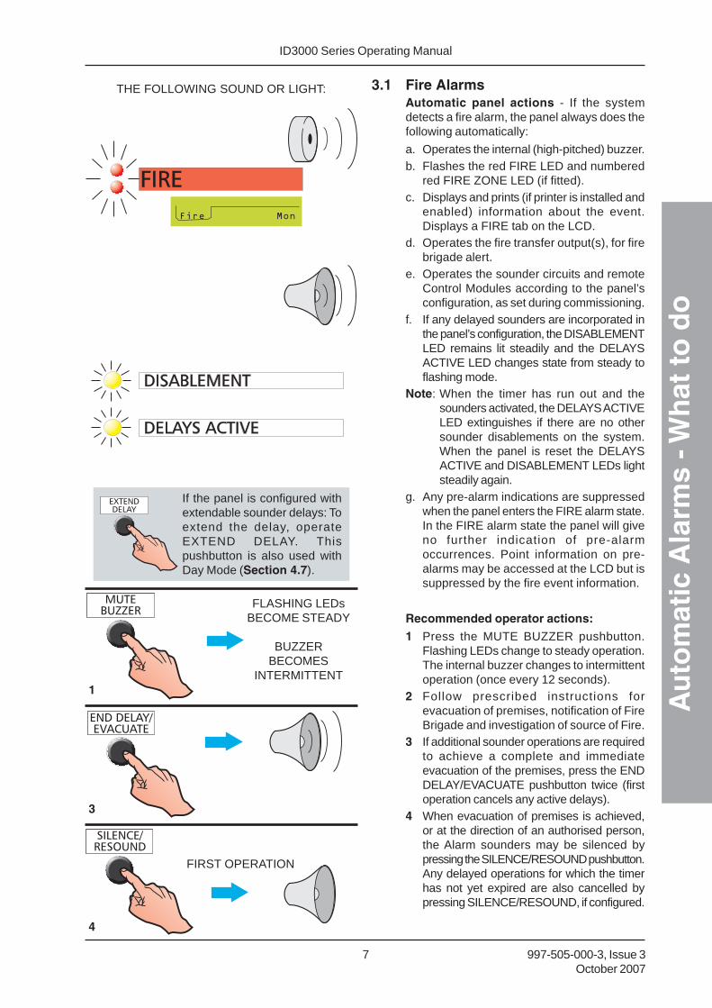
3.1 Fire AlarmsAutomatic panel actions - If the systemdetects a fire alarm, the panel always does thefollowing automatically:
a. Operates the internal (high-pitched) buzzer.b. Flashes the red FIRE LED and numbered
red FIRE ZONE LED (if fitted).c. Displays and prints (if printer is installed and
enabled) information about the event.Displays a FIRE tab on the LCD.
d. Operates the fire transfer output(s), for firebrigade alert.
e. Operates the sounder circuits and remoteControl Modules according to the panel’sconfiguration, as set during commissioning.
f. If any delayed sounders are incorporated inthe panel’s configuration, the DISABLEMENTLED remains lit steadily and the DELAYSACTIVE LED changes state from steady toflashing mode.
Note: When the timer has run out and thesounders activated, the DELAYS ACTIVELED extinguishes if there are no othersounder disablements on the system.When the panel is reset the DELAYSACTIVE and DISABLEMENT LEDs lightsteadily again.
g. Any pre-alarm indications are suppressedwhen the panel enters the FIRE alarm state.In the FIRE alarm state the panel will giveno further indication of pre-alarmoccurrences. Point information on pre-alarms may be accessed at the LCD but issuppressed by the fire event information.
Recommended operator actions:
1 Press the MUTE BUZZER pushbutton.Flashing LEDs change to steady operation.The internal buzzer changes to intermittentoperation (once every 12 seconds).
2 Follow prescribed instructions forevacuation of premises, notification of FireBrigade and investigation of source of Fire.
3 If additional sounder operations are requiredto achieve a complete and immediateevacuation of the premises, press the ENDDELAY/EVACUATE pushbutton twice (firstoperation cancels any active delays).
4 When evacuation of premises is achieved,or at the direction of an authorised person,the Alarm sounders may be silenced bypressing the SILENCE/RESOUND pushbutton.Any delayed operations for which the timerhas not yet expired are also cancelled bypressing SILENCE/RESOUND, if configured.
FIRST OPERATION
FLASHING LEDsBECOME STEADY
BUZZERBECOMES
INTERMITTENT
THE FOLLOWING SOUND OR LIGHT:
1
3
4
If the panel is configured withextendable sounder delays: Toextend the delay, operateEXTEND DELAY. Thispushbutton is also used withDay Mode (Section 4.7).

ID3000 Series Operating ManualA
uto
mat
ic A
larm
s - W
hat
to
do
8997-505-000-3, Issue 3October 2007
5 To re-start sounders after having pressedSILENCE/RESOUND, press the SILENCE/RESOUND pushbutton again.
6 When the cause of alarm has beenremoved and call points and input deviceshave been locally reset, the system maybe returned to NORMAL by pressing theRESET pushbutton.
3.2 Pre-alarms
This is the condition when one or more inputdevices has signalled a PRE-ALARM to thepanel - i.e. a reading which is higher thannormal but not yet at the FIRE level.
Automatic panel actions:
a. Steady operation of the internal (high-pitched) buzzer.
b. Flashing of amber PRE-ALARM LED.
c. Operation of those programmed controloutputs which are associated with pre-alarm events (if there are any specified inthe programmed panel configuration).
d. Display and printing (if printer is installedand enabled) of the event. Displays aPRE-ALARM tab on the LCD.
Recommended operator actions:
1 Press the MUTE BUZZER pushbutton. Theinternal buzzer changes to intermittentoperation (once every 2 minutes). FlashingPRE-ALARM lamp changes to steadyoperation.
2 Check condition of detector indicated andcheck area for possible fire. If the causecannot be determined notify authorisedServicing company.
3 When cause of pre-alarm has beencleared, press RESET pushbutton.
SECOND OPERATION
THE FOLLOWING SOUND OR LIGHT:
5
6
���������� ���������������������������
ID3000 Series Operating Manual
Au
tom
atic
Ala
rms
- Wh
at t
o d
o
9 997-505-000-3, Issue 3October 2007
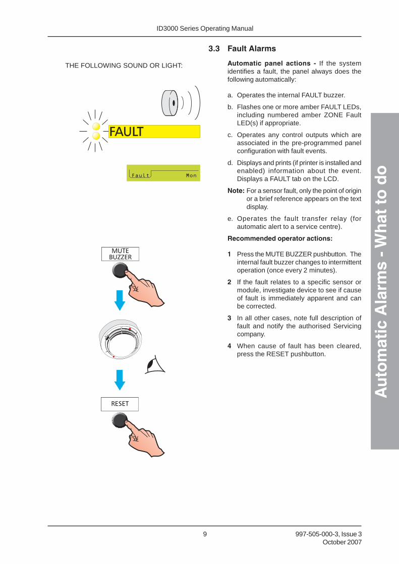
3.3 Fault Alarms
Automatic panel actions - If the systemidentifies a fault, the panel always does thefollowing automatically:
a. Operates the internal FAULT buzzer.
b. Flashes one or more amber FAULT LEDs,including numbered amber ZONE FaultLED(s) if appropriate.
c. Operates any control outputs which areassociated in the pre-programmed panelconfiguration with fault events.
d. Displays and prints (if printer is installed andenabled) information about the event.Displays a FAULT tab on the LCD.
Note: For a sensor fault, only the point of originor a brief reference appears on the textdisplay.
e. Operates the fault transfer relay (forautomatic alert to a service centre).
Recommended operator actions:
1 Press the MUTE BUZZER pushbutton. Theinternal fault buzzer changes to intermittentoperation (once every 2 minutes).
2 If the fault relates to a specific sensor ormodule, investigate device to see if causeof fault is immediately apparent and canbe corrected.
3 In all other cases, note full description offault and notify the authorised Servicingcompany.
4 When cause of fault has been cleared,press the RESET pushbutton.
THE FOLLOWING SOUND OR LIGHT:

ID3000 Series Operating ManualH
ow
to
10997-505-000-3, Issue 3October 2007
4 How to
All pushbuttons described in this sectionexcept END DELAY/EVACUATE require entryof an access 2 passcode, or the keyswitch setappropriately. If the passcode is not currentlyactive, the LCD screen displays a request forit (see Section 5.4.1). Enter the passcode and
then press the pushbutton.
Note: MUTE BUZZER and EXTEND DELAYSmay be configured in the panel tooperate at access level 1.
4.1 Evacuate (and End Delays)
If the DELAYS ACTIVE LED is flashing (panelin alarm) press the END DELAY/EVACUATEpushbutton once to end the delays.
This pushbutton also ends DAY MODEdelays (see Section 4.7).
With no delays active (DELAYS ACTIVE LEDeither lit steady if delays are configured butnot active, or not lit if delays have timed out orhave ended after first operation of the ENDDELAY/EVACUATE pushbutton):
1 Press the END DELAY/EVACUATEpushbutton.
2 If at level 1, enter the access 2 passcode
followed by . If at level 2, just press to cause sounders and other devices tooperate, if they are configured to do so.
If END DELAY/EVACUATE is pressed whilethe SILENCE/RESOUND mode is set toSILENCE, first the sounders are re-activated,then any additional actions occur as requiredby the evacuation strategy configured in thepanel.
Note: The evacuation strategy could becompletely different to the Fire alarmactions configured in the panel.
IF
IS FLASHING AMBER, THEN FIRST
OTHERWISE (LIT STEADY OR OFF), JUST
IN EITHER CASE:
IF AT LEVEL 1, ENTER THE LEVEL 2 PASSCODE.
IF ALREADY AT LEVEL 2, THE DISPLAY ISDIFFERENT:
ID3000 Series Operating Manual
Ho
w t
o
11 997-505-000-3, Issue 3October 2007
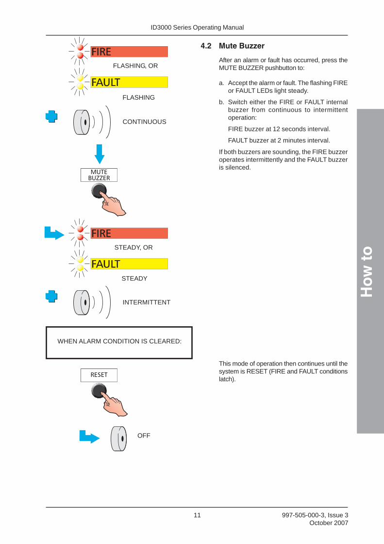
4.2 Mute Buzzer
After an alarm or fault has occurred, press theMUTE BUZZER pushbutton to:
a. Accept the alarm or fault. The flashing FIREor FAULT LEDs light steady.
b. Switch either the FIRE or FAULT internalbuzzer from continuous to intermittentoperation:
FIRE buzzer at 12 seconds interval.
FAULT buzzer at 2 minutes interval.
If both buzzers are sounding, the FIRE buzzeroperates intermittently and the FAULT buzzeris silenced.
This mode of operation then continues until thesystem is RESET (FIRE and FAULT conditionslatch).
WHEN ALARM CONDITION IS CLEARED:
FLASHING, OR
INTERMITTENT
FLASHING
CONTINUOUS
OFF
STEADY, OR
STEADY

ID3000 Series Operating ManualH
ow
to
12997-505-000-3, Issue 3October 2007
4.3 Silence/Resound Sounders
The term ‘silence’, as used throughout thismanual, describes a temporary state the panelenters whenever the SILENCE/RESOUNDpushbutton is pressed to stop the soundersoperating. While the panel is in this state, anew fire alarm, or operation of the ENDDELAY/EVACUATE pushbutton, will re-soundall previously-silenced sounders.
To cancel all sounder output delays and allsounder outputs which are operating as aresult of a FIRE alarm or an EVACUATEoperation:
1 Press the SILENCE/RESOUNDpushbutton. The following are not switchedoff by this operation:
a. The internal FIRE buzzer (except in thecase detailed below).
b. Any external Control Modules thathave been programmed not to besilenced by SILENCE/RESOUND.
2 To start the sounders again in the samepattern as they were previously operating,press the SILENCE/RESOUNDpushbutton.
Note: SILENCE/RESOUND works for a firecondition only, not for an operation ofthe END DELAY/EVACUATE pushbutton.
Note: When the sounders are restarted, theinternal fire sounder will also changeback to steady mode of operation andyou may have to press MUTE BUZZERagain.
OR
(SEE SECTION 4.1)
SILENCE
TO RE-SOUND FROM FIRE ONLY(DOES NOT WORK FROM EVACUATE)
ID3000 Series Operating Manual
Ho
w t
o
13 997-505-000-3, Issue 3October 2007
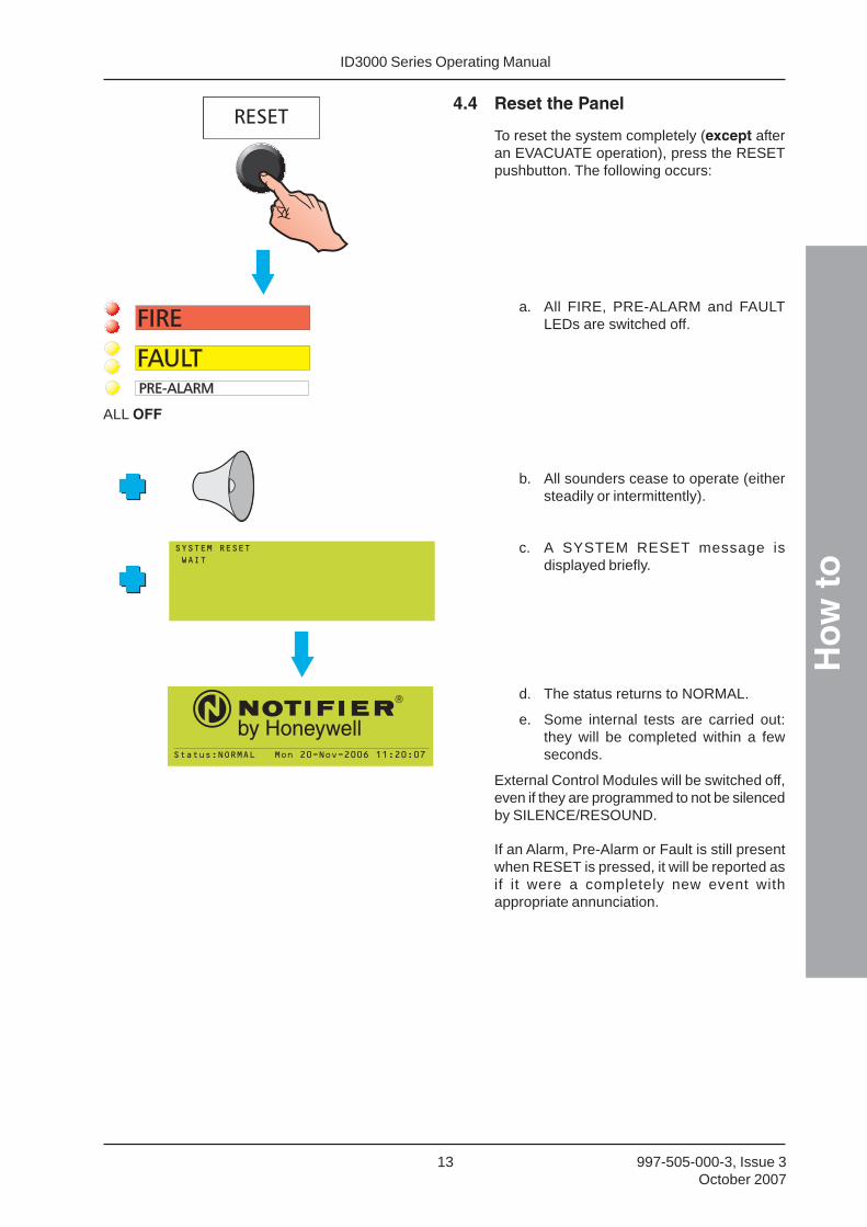
4.4 Reset the Panel
To reset the system completely (except afteran EVACUATE operation), press the RESETpushbutton. The following occurs:
a. All FIRE, PRE-ALARM and FAULTLEDs are switched off.
b. All sounders cease to operate (eithersteadily or intermittently).
c. A SYSTEM RESET message isdisplayed briefly.
d. The status returns to NORMAL.
e. Some internal tests are carried out:they will be completed within a fewseconds.
External Control Modules will be switched off,even if they are programmed to not be silencedby SILENCE/RESOUND.
If an Alarm, Pre-Alarm or Fault is still presentwhen RESET is pressed, it will be reported asif it were a completely new event withappropriate annunciation.
ALL OFF
���������� ���������������������������

ID3000 Series Operating ManualH
ow
to
14997-505-000-3, Issue 3October 2007
4.5 Disable/Enable Devices and Zones(Quick Method)
This allows a device or zone to be:
a. Disabled quickly if the Fire tab is current,and then re-enabled.
b. Disabled quickly if the Pre-alarm tab iscurrent, and re-enabled. Devices only.
c. Enabled quickly if the Disable tab is current,or fully-disable a partially-disabled zone.
4.5.1 From Fire Tab
Device
The example shows how to disable anindividual device when the Fire tab is displayed.This method also applies to Virtual Input Points(ID2net only: points may be on remote panels).
Further details about the Fire tab are given inSection 5.3.1, Fire Alarm Event Display.
Networked systems only - the currentenablement status of a device on a remotepanel is unknown to the local panel, so theoptions shown below are given instead of theprompt shown at left.
USE ONCE, ENTERPASSCODE, THEN
REPEATEDUSE UNTIL
Repeating this procedure displays the optionto enable the disabled device.
Zone
Alternatively, press when DISABLE THISZONE is highlighted, then select either ALLSENSORS or ALL INPUTS (this choice is notprovided for remote networked panels). Aconfirmation prompt is then displayed.
Repeating this procedure displays the optionto enable the disabled zone.
ID3000 Series Operating Manual
Ho
w t
o
15 997-505-000-3, Issue 3October 2007
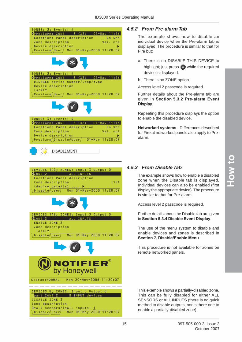
4.5.2 From Pre-alarm Tab
The example shows how to disable anindividual device when the Pre-alarm tab isdisplayed. The procedure is similar to that forFire but:
a. There is no DISABLE THIS DEVICE to
highlight; just press while the requireddevice is displayed.
b. There is no ZONE option.
Access level 2 passcode is required.
Further details about the Pre-alarm tab aregiven in Section 5.3.2 Pre-alarm EventDisplay.
Repeating this procedure displays the optionto enable the disabled device.
Networked systems - Differences describedfor Fire at networked panels also apply to Pre-alarm.
4.5.3 From Disable Tab
The example shows how to enable a disabledzone when the Disable tab is displayed.Individual devices can also be enabled (firstdisplay the appropriate device). The procedureis similar to that for Pre-alarm.
Access level 2 passcode is required.
Further details about the Disable tab are givenin Section 5.3.4 Disable Event Display.
The use of the menu system to disable andenable devices and zones is described inSection 7, Disable/Enable Menu.
This procedure is not available for zones onremote networked panels.
This example shows a partially-disabled zone.This can be fully disabled for either ALLSENSORS or ALL INPUTS (there is no quickmethod to disable outputs, nor is there one toenable a partially-disabled zone).
���������� ���������������������������

ID3000 Series Operating ManualH
ow
to
16997-505-000-3, Issue 3October 2007
4.6 Discontinue a Walk Test (QuickMethod)
The example shows how to cancel a walk testwhen the Test tab is present.
Access level 2 passcode is required.
The left arrow only applies if there is more thanone zone in test. The Panel name is only givenif the panel is on a network and using local(panel) zone numbering.
When the ‘ ‘ pushbutton is operated:
a. If multiple zones are in test the promptindicates that all zones will be cancelled. Itis not possible to choose zone(s) forcancellation of the test.
b. If only one zone is in test, this zone isexplicitly named in the prompt.
Further details about the Test tab are given inSection 5.3.5 Test Event Display.
The use of the menu system to start and stopthe zone walk test is described in Section 6.2Zone Walk Test.
���� ����������������
����������������������� �� !���
��� "����� #�$%�&�''%# ��������� ����(
��%��#�$$%!�$
� ���$�����%! �$��)�*���������������
� ���+� $�������� ����,�"����-���������
� �� !�(
OR, IF ONLY ONE ZONE IN TEST:
.��.� �������/���� �����
0�1234
� ���+� $�������� ����,�"����-���������
.��.� �������/������� ��������
0�1234
� ���+� $�������� ����,�"����-���������
ID3000 Series Operating Manual
Ho
w t
o
17 997-505-000-3, Issue 3October 2007
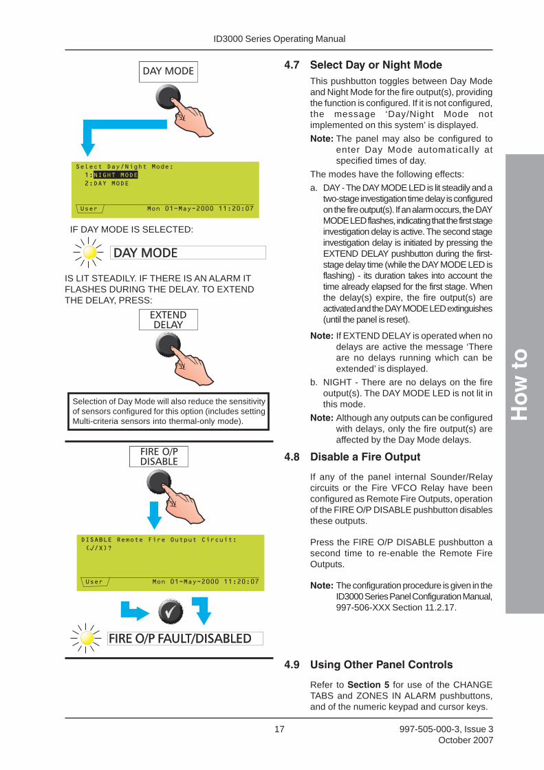
4.7 Select Day or Night ModeThis pushbutton toggles between Day Modeand Night Mode for the fire output(s), providingthe function is configured. If it is not configured,the message ‘Day/Night Mode notimplemented on this system’ is displayed.
Note: The panel may also be configured toenter Day Mode automatically atspecified times of day.
The modes have the following effects:
a. DAY - The DAY MODE LED is lit steadily and atwo-stage investigation time delay is configuredon the fire output(s). If an alarm occurs, the DAYMODE LED flashes, indicating that the first stageinvestigation delay is active. The second stageinvestigation delay is initiated by pressing theEXTEND DELAY pushbutton during the first-stage delay time (while the DAY MODE LED isflashing) - its duration takes into account thetime already elapsed for the first stage. Whenthe delay(s) expire, the fire output(s) areactivated and the DAY MODE LED extinguishes(until the panel is reset).
Note: If EXTEND DELAY is operated when nodelays are active the message ‘Thereare no delays running which can beextended’ is displayed.
b. NIGHT - There are no delays on the fireoutput(s). The DAY MODE LED is not lit inthis mode.
Note: Although any outputs can be configuredwith delays, only the fire output(s) areaffected by the Day Mode delays.
4.8 Disable a Fire Output
If any of the panel internal Sounder/Relaycircuits or the Fire VFCO Relay have beenconfigured as Remote Fire Outputs, operationof the FIRE O/P DISABLE pushbutton disablesthese outputs.
Press the FIRE O/P DISABLE pushbutton asecond time to re-enable the Remote FireOutputs.
Note: The configuration procedure is given in theID3000 Series Panel Configuration Manual,997-506-XXX Section 11.2.17.
4.9 Using Other Panel Controls
Refer to Section 5 for use of the CHANGETABS and ZONES IN ALARM pushbuttons,and of the numeric keypad and cursor keys.
IF DAY MODE IS SELECTED:
IS LIT STEADILY. IF THERE IS AN ALARM ITFLASHES DURING THE DELAY. TO EXTENDTHE DELAY, PRESS:
Selection of Day Mode will also reduce the sensitivityof sensors configured for this option (includes settingMulti-criteria sensors into thermal-only mode).

ID3000 Series Operating ManualT
he
Dis
pla
y - T
abs,
Eve
nts
an
d M
enu
s
18997-505-000-3, Issue 3October 2007
5 The Display - Tabs, Eventsand Menus
5.1 Introduction
5.1.1 Status: NORMAL
The Status: NORMAL display appears when:
a. No alarm or test conditions exist, and
b. No menus are being accessed.
Other NORMAL indications:POWER LED (green) ONOther LEDs OFFInternal buzzers OFFInternal sounder circuits OFFFIRE, FAULT relays OFFControl modules OFF (unless operated by
an auxiliary action)The built-in LED indicators on all sensors and modules shouldeither give short pulses or be off altogether.
5.1.2 Tabs
When conditions other than Status: NORMALexist, the LCD displays event data. More thanone type of data may be available for displayat any one time (eg, Fire Alarms, Faults, Menusetc.). When this occurs, the types of dataavailable are identified by tabs at the bottomof the display.
5.1.3 Events
Fire Alarms, Pre-alarms, Faults, Disablements,Tests, Evacuate mode, and Auxiliary inputactivations are shown on Event displays. AFault event display is shown. On networkedpanels the ‘Location’ text is replaced by thepanel type (e.g. Master, Slave 1 etc).
5.1.4 Menus
Menus are arranged in a heirarchy, the top ofwhich is the User Menu from which othermenus are accessed.
���������� ���������������������������
ID3000 Series Operating Manual
Th
e D
isp
lay
- Tab
s, E
ven
ts a
nd
Men
us
19 997-505-000-3, Issue 3October 2007
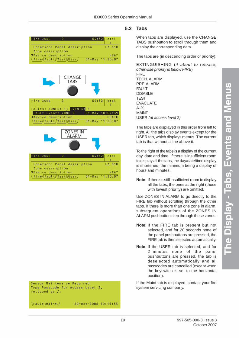
5.2 Tabs
When tabs are displayed, use the CHANGETABS pushbutton to scroll through them anddisplay the corresponding data.
The tabs are (in descending order of priority):
EXTINGUISHING ( i f about to release;otherwise priority is below FIRE)FIRETECH. ALARMPRE-ALARMFAULTDISABLETESTEVACUATEAUXMAINTUSER (at access level 2)
The tabs are displayed in this order from left toright. All the tabs display events except for theUSER tab, which displays menus. The currenttab is that without a line above it.
To the right of the tabs is a display of the currentday, date and time. If there is insufficient roomto display all the tabs, the day/date/time displayis shortened, the minimum being a display ofhours and minutes.
Note: If there is still insufficient room to displayall the tabs, the ones at the right (thosewith lowest priority) are omitted.
Use ZONES IN ALARM to go directly to theFIRE tab without scrolling through the othertabs. If there is more than one zone in alarm,subsequent operations of the ZONES INALARM pushbutton step through these zones.
Note: If the FIRE tab is present but notselected, and for 20 seconds none ofthe panel pushbuttons are pressed, theFIRE tab is then selected automatically.
Note: If the USER tab is selected, and for2 minutes none of the panelpushbuttons are pressed, the tab isdeselected automatically and allpasscodes are cancelled (except whenthe keyswitch is set to the horizontalposition).
If the Maint tab is displayed, contact your firesystem servicing company.
��������������������������
�� ��!��������"���������� ���#�$%
"�##�&���'����
(��#�������)����������������������*�$$

ID3000 Series Operating ManualT
he
Dis
pla
y - T
abs,
Eve
nts
an
d M
enu
s
20997-505-000-3, Issue 3October 2007
5.3 Event Displays
5.3.1 Extinguishing System Display
This tab displays the Extinguishing Systemstatus. There is no status message associatedwith the AUTO mode.
The zone text is that of the zone in which thefirst device found as an OUTPUT in the ControlMatrix is placed for this Extinguishing System.
If there is more than one Extinguishing System,
arrows are displayed. Use the and arrows to scroll through the available systems.
The ‘WEIGHT LOSS’ message has higherpriority than any other except the‘Extinguishant RELEASED’ message. It is notshown if extinguishant has been released bypanel action.
(continued)

ID3000 Series Operating Manual
Th
e D
isp
lay
- Tab
s, E
ven
ts a
nd
Men
us
21 997-505-000-3, Issue 3October 2007
During an alarm, the tab’s display iscompressed to allow Fire information to bedisplayed. If the Extinguishing System has adelay configured, the delay time remaining isdisplayed both numerically and by means of atimer bar.
If the HOLD switch is configured in this panelto restart the delay timer when it is released,the timer bar is not displayed when HOLD isselected.

ID3000 Series Operating ManualT
he
Dis
pla
y - T
abs,
Eve
nts
an
d M
enu
s
22997-505-000-3, Issue 3October 2007
5.3.2 Fire Alarm Event Display
If a Fire is detected, the Fire tab is selectedautomatically to show the Fire Alarm Event Display:
a. ‘Fire ZONE’ field shows zone(s) in alarm(in this case zone 2), the number of devicesin alarm in that zone (X2 = 2 devices) andthe time at which the first alarm occurredin the zone. Network systems only: thepanel number is also shown (e.g. P0 formaster, P1 for slave 1 etc).
b. ‘Total’ field gives the number of zones in alarmon the panel, or (if networked) on the system.
c. ‘Description’ field displays the event data.
Section 5.2 describes the tab and day/date/time fields.
The and arrows step through thedevices, when more than one device is in alarmin the zone. If the panel is configured to uselocal zones, each device is identified by its loopnumber (Lnn) and device number (Snn forsensors, Mnn for modules). If the panel isconfigured to use network zones, each deviceis identified by its zone number (nnnn) andreference number (nn) in the format nnnn/nn.For Virtual Input Points, the point number isdisplayed (e.g. VIP10).
The and arrows step through additionaldata and options about the device in alarm.You must be at least at access level 2 to dothis; if you are not a passcode prompt will appear.
Refer to Section 4.5 for details of thedisablement options.
If the CHANGE TABS pushbutton is used todisplay other data (another type of event or amenu), the display area is reformatted so thatthe top two lines continue to display fireinformation. The Fire tab information isautomatically re-displayed after 20 seconds.
(continued on next page)
REPEATED USE(ENTER PASSCODE
IF PROMPTED)
REPEATED USE
Other FIRE indications:Note: The term ‘accepted’ means that the MUTE BUZZERpushbutton has been operated, or a user operation has beencarried out.POWER LED (green) ONFIRE LEDs (red) if not accepted: FLASHING
if accepted: STEADY(if a new alarm occurs, flashes again until accepted)ZONE LEDs (if fitted, for zones in which fires have beendetected - red)
if not accepted: FLASHINGif accepted: STEADY
Internal buzzers If not accepted: Fire buzzer (high-pitched): Fast pulse, 0.5 sec ON
0.5 sec OFF
If accepted or buzzer silenced: Fire buzzer (muted): ON intermittently
3 x 0.5 sec pulses, 0.5 sec apartfollowed by 10.5 sec OFF
Internal sounder circuits (unless configured otherwise) STEADYFIRE relay ONFAULT relay OFFControl modules As configuredThe built-in LED indicators on the sensors and modules whichissued the alarm will be on STEADY if the alarm input conditionsstill exist, otherwise they will show 1 second on/1 second offpulses (possibly with intervening short pulses). The LEDs ofactive Control Modules (those for which the control output isON) will be OFF. The LEDs of all other sensors and modulesshould either give short pulses or be off altogether, dependingupon the configuration.
SPECIAL CASE. The Fire tab will display GENERAL FIRESIGNAL ACTIVATED without an indication of the originatingdevice or zone, if one of the following occurs:
a. IF ELIBS ARE FITTED - If the panel loses communicationswith an ELIB which then detects a fire, and the panelsoftware is still running.
b. IF PANEL IS ON ID2NET network - If the primary processoron a Network PCB (NGM) fails and its secondaryprocessor sends a backup fire signal.

ID3000 Series Operating Manual
Th
e D
isp
lay
- Tab
s, E
ven
ts a
nd
Men
us
23 997-505-000-3, Issue 3October 2007
When more than one zone is in alarm, useZONES IN ALARM to step through the zones.
In this example (for illustrative purposes only)three zones are in alarm:
a. The first fire is in zone 2 and there are twodevices in alarm in that zone.
b. The second fire is in zone 16 and onedevice is in alarm in that zone.
c. The third (and latest) fire is in zone 1 andone device is in alarm in that zone. LATESTFire ZONE is always displayed.
Other PRE-ALARM indications:Note: The term ‘accepted’ means that the MUTE BUZZERpushbutton has been operated.POWER LED (green) ONPRE-ALARM LED (amber) if not accepted: FLASHING
if accepted: STEADYOther LEDs OFFInternal buzzers If not accepted: Pre-alarm buzzer (high-pitched): ON STEADY If accepted or buzzer silenced: Pre-alarm buzzer (muted): Intermittent - one 0.5 sec pulse
every 2 minutesCircuits controlled internally and control modules perform theirconfigured functions.
���+)�#��,��-�.����/�.��������
!���#��$����������""������������ 0���*
1���������$
1��#��2���������������������������3��
���+)�#��,�4����������5�#����0���������
!�$�-�.���$��67�8������������5�#������
5.3.3 Pre-alarm Event Display
Provided the panel is not in alarm, if any deviceis in pre-alarm the Pre-alarm tab is displayed.
The display is similar to Fire (includingdifferences when networked) but only one zoneis shown at a time. A summary of the numberof zones affected and the number of pre-alarmevents is given at the top of the display. In thisexample, three zones are in pre-alarm and thereare four events, two of which are in zone 8 whichis currently displayed.
Use the and arrows to step through thezones when more than one zone is in pre-alarm.
Use the and arrows to step through thedevices, when more than one device is in alarmin the zone. Each device is identified by itsloop number and address number, either sensor(S) or module (M).
5.3.4 Technical Alarm Display
The Tech. Alarm tab is displayed when any GasSensor Interface configured as Technical Alarmis activated. Indications as the same as for FireAlarm except that the Technical Alarm LEDilluminates instead of the common FIRE LEDand zonal LED(s) do not illuminate.
ID3000 Series Operating ManualT
he
Dis
pla
y - T
abs,
Eve
nts
an
d M
enu
s
24997-505-000-3, Issue 3October 2007
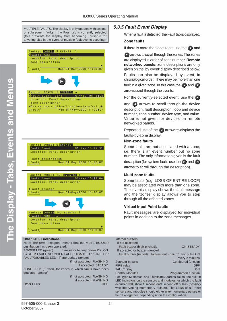
5.3.5 Fault Event Display
When a fault is detected, the Fault tab is displayed.
Zone faults
If there is more than one zone, use the and
arrows to scroll through the zones. The zonesare displayed in order of zone number. Remotenetworked panels: zone descriptions are onlygiven on the ‘by event’ display described below.
Faults can also be displayed by event, inchronological order. There may be more than one
fault in a given zone. In this case the and arrows scroll through the events.
For the currently-selected event, use the
and arrows to scroll through the devicedescription, fault description, loop and devicenumber, zone number, device type, and value.Value is not given for devices on remotenetworked panels.
Repeated use of the arrow re-displays thefaults-by-zone display.
Non-zone faultsSome faults are not associated with a zone;i.e. there is an event number but no zonenumber. The only information given is the fault
description (for system faults use the and arrows to scroll through the description).
Multi-zone faults
Some faults (e.g. LOSS OF ENTIRE LOOP)may be associated with more than one zone.The ‘events’ display shows the fault messageand the ‘zones’ display allows you to stepthrough all the affected zones.
Virtual Input Point faults
Fault messages are displayed for individualpoints in addition to the zone messages.
Other FAULT indications:Note: The term ‘accepted’ means that the MUTE BUZZERpushbutton has been operated.POWER LED (green) if mains or battery power OK: ONSYSTEM FAULT, SOUNDER FAULT/DISABLED or FIRE O/PFAULT/DISABLED LED - if appropriate (amber)
if not accepted: FLASHINGif accepted: STEADY
ZONE LEDs (if fitted, for zones in which faults have beendetected - amber)
if not accepted: FLASHINGif accepted: FLASHING
Other LEDs OFF
Internal buzzers If not accepted: Fault buzzer (high-pitched): ON STEADY If accepted or buzzer silenced: Fault buzzer (muted): Intermittent - one 0.5 sec pulse ON
every 2 minutesSounder circuits Configured functionFIRE relay OFFFAULT relay ONControl Modules Programmed functionFor ‘Type Mismatch’ and ‘Duplicate Address’ faults, the built-inLED indicators on the sensors and modules for which the faultoccurred will show 1 second on/1 second off pulses (possiblywith intervening momentary pulses). The LEDs of all othersensors and modules should either give momentary pulses orbe off altogether, depending upon the configuration.
MULTIPLE FAULTS. The display is only updated with secondor subsequent faults if the Fault tab is currently selected(this prevents the display from becoming unusable foranything else in the event of multiple fault events occuring).
ID3000 Series Operating Manual
Th
e D
isp
lay
- Tab
s, E
ven
ts a
nd
Men
us
25 997-505-000-3, Issue 3October 2007
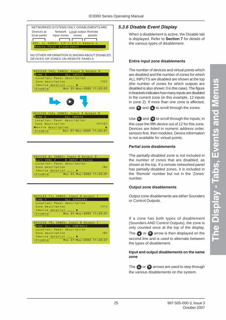
5.3.6 Disable Event Display
When a disablement is active, the Disable tabis displayed. Refer to Section 7 for details ofthe various types of disablement.
Entire input zone disablements
The number of devices and virtual points whichare disabled and the number of zones for whichALL INPUTS are disabled are shown at the top(the number of zones for which outputs aredisabled is also shown; 0 in this case). The figurein brackets indicates how many inputs are disabledin the current zone (in this example, 12 inputsin zone 2). If more than one zone is affected,
use and to scroll through the zones.
Use and to scroll through the inputs; inthis case the fifth device out of 12 for this zone.Devices are listed in numeric address order,sensors first, then modules. Device informationis not available for virtual points.
Partial zone disablements
The partially-disabled zone is not included inthe number of zones that are disabled, asshown at the top. If a remote networked panelhas partially-disabled zones, it is included inthe ‘Remote’ number but not in the ‘Zones’number.
Output zone disablements
Output zone disablements are either Soundersor Control Outputs.
If a zone has both types of disablement(Sounders AND Control Outputs), the zone isonly counted once at the top of the display.
The or arrow is then displayed on thesecond line and is used to alternate betweenthe types of disablement.
Input and output disablements on the samezone
The or arrows are used to step throughthe various disablements on the system.
NETWORKED SYSTEMS ONLY, DISABLEMENTS ARE:Devices atlocal panel
Networkinput zones
Local outputzones
Remotepanels
NO OTHER INFORMATION IS SHOWN ABOUT DISABLEDDEVICES OR ZONES ON REMOTE PANELS.

ID3000 Series Operating ManualT
he
Dis
pla
y - T
abs,
Eve
nts
an
d M
enu
s
26997-505-000-3, Issue 3October 2007
Sounder/relay circuit disablements
Sounder and relay circuits, remote fire outputs,and the fire and fault relays are not allocatedto a zone. They are listed at the end of the listof zone disablements (if any).
Other DISABLE indications:POWER LED (green) ONDISABLEMENT LED (amber) ONSOUNDER FAULT/DISABLED or FIRE O/P FAULT/DISABLEDLED - if appropriate (amber) ONZONE LEDs (if fitted, for zones in which ALL input deviceshave been disabled - amber) ONOther LEDs OFFFault buzzer: intermittent - one 0.5 sec pulse
followed by 11.5 sec OFFCircuits controlled internally and control modules perform theirprogrammed function.
5.3.7 Test Event Display
The Test tab is displayed either when a zonewalk test is in progress or when a Daily or Weeklyautomatic test is in progress. Automatic testscannot occur while a walk test is in progress,and vice versa.
Zone walk test
If there is more than one zone in test, the initial
display is as shown at (i). Use the and
arrows to scroll through the zones and the arrow to display device test details for thecurrent zone as shown at (ii).
On the device display (ii), use the and arrows to scroll through the devices. Use the
arrow to return to the initial display (i) and
the arrow to display further device
information ( arrow to return). For thecurrently-displayed device, either ‘Tested’ (ii)or ‘Not Tested’ (iii) is highlighted, dependingupon whether the device has been activated(e.g. with a smoke or magnet test) or not.
If only one zone is in test, the device test detailsis the initial display and there is no left arrowsince there is no zone display to return to.
When a device is tested it automaticallybecomes the device selected for display.
Other TEST indications:POWER LED (green) ONTEST LED (amber) ONZONE LEDs (if fitted, for zones in test - amber) ONOther LEDs OFFInternal buzzers, sounder circuits, FIRE, FAULT relays OFFControl modules OFFThe built-in LED indicators on the sensors in the zone in test show1 second on/1 second off pulses (possibly with intervening shortpulses). The LEDs of all other sensors and modules should eithergive short pulses or be off altogether, as configured.
0�-�.��9���.��
9� ������������$/��������������
!���#�������������""���
�����1�������
�����4����������������5�#����0���������
!��. ���-�.�:�9���.��
!��. ���-�.�:�9���.��
9� �������������/��������������
!���#�������������""������������ ����$
�������������
������������������,�*�������������9�
�����4����������������5�#����0���������
�������$
!��. ���-�.�:�9���.��
9� ������������$/
!���#�������������""������������ �����
�������������
1�##�!�������������;���������������1!
�����4����������������5�#����0���������
�������������
(i)
(ii)
(iii)
Master/Slave network with local zones: if the zonein test is on a remote panel, only the zone numberand panel name are displayed.

ID3000 Series Operating Manual
Th
e D
isp
lay
- Tab
s, E
ven
ts a
nd
Men
us
27 997-505-000-3, Issue 3October 2007
Automatic test
This display is automatically provided when thepanel undergoes an automatic test (the panelmay be configured to do this either daily orweekly, but not both).
Networked systems - test display is onlyprovided at panel under test. More than onepanel may be in automatic test simultaneously.
5.3.8 Evacuate Event Display
During evacuate, the Evacuate tab isdisplayed. The Evacuate event displayidentifies the panel that initiated the Evacuate.
Other EVACUATE indications:POWER LED (green) ONOther LEDs OFFInternal buzzers OFFInternal sounder circuits (unless otherwise configured) STEADYFIRE, FAULT relays OFFControl modules As configuredThe built-in LED indicators of active control modules (those forwhich the control output is ON) will be OFF. The LEDs of allother sensors and modules should either give momentarypulses or be off altogether, as configured.
5.3.9 Auxiliary Event Display
The Aux tab indicates activations of non-alarmnon-latching inputs (i.e. modules of logical typeAUX). Activations are listed in chronological
order; use the and arrows to stepthrough them. The tab is removed when thelast AUX input is de-activated.
Note: If the AUX module is configured forindication, the heading ‘AUX. Input’becomes ‘INDICATION’.
Note: If the AUX tab displays the message‘Unconfigured Device found on loop’,inform the fire alarm system maintainingcompany.
Note: For Virtual Input Points, the pointnumber is displayed (e.g. VIP5).

ID3000 Series Operating ManualT
he
Dis
pla
y - T
abs,
Eve
nts
an
d M
enu
s
28997-505-000-3, Issue 3October 2007
5.4 Menu Displays
5.4.1 To Display the User Menu
To display the User Menu when the systemstatus is Normal, either press CHANGE TABSand enter the access 2 passcode, or operatethe keyswitch.
Note: If event tabs are displayed, CHANGETABS first displays these sequentially,then when the last of these has beendisplayed the passcode prompt isdisplayed.
Note: If no further pushbuttons are pressedthe Status: NORMAL display is re-displayed after 2 minutes.
The User tab is displayed with the menu.
Only the first four options of the User Menuare displayed at this time. The selected option
is highlighted. Use the and keys toscroll through the other options.
Use the key to return to the Status:NORMAL display.
ACCESS 2PASSCODE, THEN
(REPEATEDLY)
OR
EITHER: OR:
���������� ���������������������������
���������� ���������������������������

ID3000 Series Operating Manual
Th
e D
isp
lay
- Tab
s, E
ven
ts a
nd
Men
us
29 997-505-000-3, Issue 3October 2007
5.4.2 To Navigate Through the Menus
In this example it is desired to display the TestMenu, which is option 1 on the User Menu.
With the User Menu displayed, press to
go to the Test Menu directly ( correspondsto its option number on the User Menu).
Alternatively, highlight option 1 on the UserMenu and then select the option by pressing
or .
Press the key to exit from the menu.
(REPEATEDLYUNTIL CURSOR ISBESIDE OPTION 1)
OR OR
OR

ID3000 Series Operating ManualT
he
Dis
pla
y - T
abs,
Eve
nts
an
d M
enu
s
30997-505-000-3, Issue 3October 2007
5.4.3 Menu Structure
Note: ** Selecting this menu option displays a prompt for an access 3 passcode, thus the option is notavailable to the operator (its use by configuration personnel is described in the ID3000 SeriesPanel Configuration Manual 997-506-XXX). Some additional menu options are available at accesslevel 3 only and are not shown below.
+Only available if a PRN-ID or P40 printer is configured.
Some menus prompt for a zone selection before the next level down menu is displayed.
STATUS: NORMAL
DISABLE/ENABLE
INDIVIDUAL DEVICE
DISABLE ALL
INPUTS
DISABLE SENSORS
ONLY
ENABLE ALL
INPUTS
ALARM OUTPUTS
BY ZONE
DISABLE
SOUNDERS
DISABLE CONTROL
OUTPUTS
ENABLE
SOUNDERS
ENABLE CONTROL
OUTPUTS
SENSOR
LOG/DISPLAY/
PRINT MENU
LOG/DISPLAY
DEVICE DATA
PRINT DEVICE
DATA
SET CLOCK
SET LANGUAGE
ENTER LEVEL 3
PASSCODE ** DISPLAY/PRINT
EVENT LOG
USER MENU
SENSOR
ALARM INPUTS
BY ZONE
MODULE
TEST ZONE WALK TEST
CONTROL OUTPUT/
SOUNDER TEST **
DAILY/WEEKLY AUTO
TEST NOW
LAMP TEST
REPLACE VIEW
SENSORS **
SOUNDER/RELAY
CIRCUIT
MODULE
SENSORS AND
MODULES
SENSORS
MODULES
PRINTER
CONTROL +
VIEW ALARM
COUNT
VIRTUAL OUTPUT
POINT
VIRTUAL INPUT
POINT
SMART SENSORS
COMMISSIONING **
ID3000 Series Operating Manual
Test
Men
u
31 997-505-000-3, Issue 3October 2007
6 Test Menu
6.1 Introduction
The test menu has options which allow you to:
a. Perform a zone walk test (see Section 6.2).
b. Perform an individual control output test(see Section 6.3).
c. Perform a lamp test (see Section 6.4).
d. Perform a daily or weekly automatic teston sensors (see Section 6.5).
e. Recalibrate a VIEW sensor (seeSection 6.6).
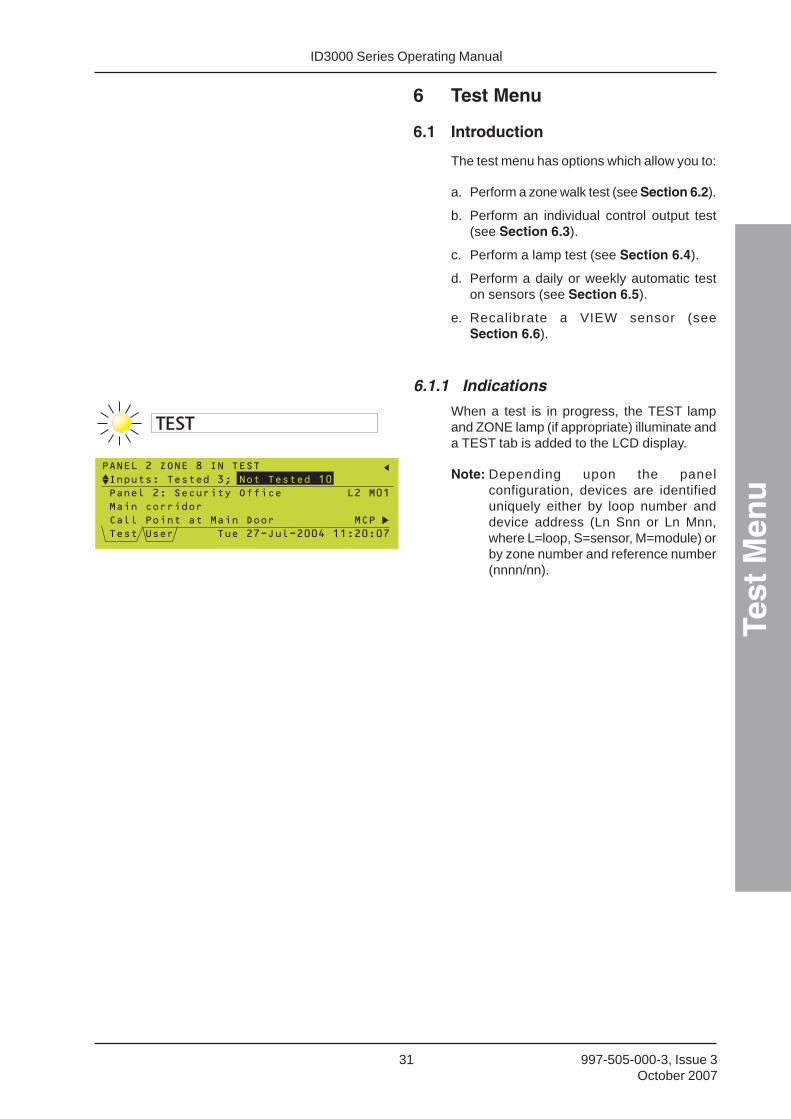
6.1.1 Indications
When a test is in progress, the TEST lampand ZONE lamp (if appropriate) illuminate anda TEST tab is added to the LCD display.
Note: Depending upon the panelconfiguration, devices are identifieduniquely either by loop number anddevice address (Ln Snn or Ln Mnn,where L=loop, S=sensor, M=module) orby zone number and reference number(nnnn/nn).
���������������� ��
�������� ��������
����������������������������������� !"
�����#����#�
$�����#������� ����%##������������ $�
����&��������� ����'()��(�!!*�""��!�!'
�#�� ������"!
ID3000 Series Operating ManualTe
st M
enu
32997-505-000-3, Issue 3October 2007
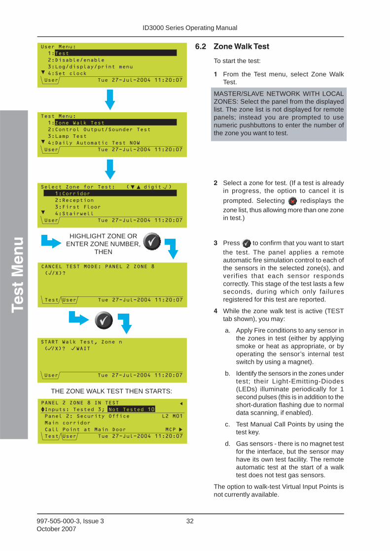
6.2 Zone Walk Test
To start the test:
1 From the Test menu, select Zone WalkTest.
MASTER/SLAVE NETWORK WITH LOCALZONES: Select the panel from the displayedlist. The zone list is not displayed for remotepanels; instead you are prompted to usenumeric pushbuttons to enter the number ofthe zone you want to test.
2 Select a zone for test. (If a test is alreadyin progress, the option to cancel it is
prompted. Selecting redisplays thezone list, thus allowing more than one zonein test.)
3 Press to confirm that you want to startthe test. The panel applies a remoteautomatic fire simulation control to each ofthe sensors in the selected zone(s), andverifies that each sensor respondscorrectly. This stage of the test lasts a fewseconds, during which only failuresregistered for this test are reported.
4 While the zone walk test is active (TESTtab shown), you may:
a. Apply Fire conditions to any sensor inthe zones in test (either by applyingsmoke or heat as appropriate, or byoperating the sensor’s internal testswitch by using a magnet).
b. Identify the sensors in the zones undertest; their Light-Emitting-Diodes(LEDs) illuminate periodically for 1second pulses (this is in addition to theshort-duration flashing due to normaldata scanning, if enabled).
c. Test Manual Call Points by using thetest key.
d. Gas sensors - there is no magnet testfor the interface, but the sensor mayhave its own test facility. The remoteautomatic test at the start of a walktest does not test gas sensors.
The option to walk-test Virtual Input Points isnot currently available.
HIGHLIGHT ZONE ORENTER ZONE NUMBER,
THEN
THE ZONE WALK TEST THEN STARTS:
&���� ����
"�
��%���+��,���+��
���#-,�������,������.���
*�������#�/
&�������������� ����'()��(�!!*�""��!�!'
���
���� ����
"�
��$#���#�������,�#������ ���
����.�� ���
*�%��������#.����� �����0
&�������������� ����'()��(�!!*�""��!�!'
#���0��/� ���
�������#����#�� �������1������-����2
��3������#�
��4�����4�##�
*������5���
&�������������� ����'()��(�!!*�""��!�!'
"�$#����#�
$��$��� �� � %���������������
1�,627
����&��������� ����'()��(�!!*�""��!�!'
� �3 �0��/� ���8�#����
1�,627���0��
&�������������� ����'()��(�!!*�""��!�!'
���������������� ��
�������� ��������
����������������������������������� !"
�����#����#�
$�����#������� ����%##������������ $�
����&��������� ����'()��(�!!*�""��!�!'
�#�� ������"!

ID3000 Series Operating Manual
Test
Men
u
33 997-505-000-3, Issue 3October 2007
Each test operation is logged in the EventHistory, recorded on the printer (if fitted) anddisplayed on the LCD. When a device is tested,‘Tested’ increments by one and ‘Not Tested’
decrements by one. Use and to select
the device to be displayed, and and toscroll through the information about that device.
The following checks allow certain devices to beeasily checked for correct operation:
a. Analogue sensors - observe that thesensor’s LED changes to steady ON status,returning to pulsing mode about 5 secondsafter the test condition is removed.
b. Manual Call Points - the appropriatesounder outputs are activated (accordingto the specified test requirements), eitherfor approximately one second, or for as longas the call point test key is left in (dependingon configuration). Only the internal soundercircuits and outputs designated as typeBELL are involved.
A test may be applied to any point any numberof times; test alarms are auto-resetting. Waitat least 5 seconds before re-testing a device.
To end the test before all devices have been
tested, re-select the zone. Press to confirmthat you want to stop the test. If multiple zonesare in test, the test is stopped for all zones.
Note: Also see Section 4.6 for the quickmethod to cancel a walk test.
6.3 Control Output Tests
This menu option prompts for an access level3 passcode. It is not available to the operator.
TO CANCEL THE TEST, REPEAT THEPROCEDURE USED TO START IT, THEN:
5 SECONDS
$��$��� �� � %���������������
1�,627
����&��������� ����'()��(�!!*�""��!�!'

ID3000 Series Operating ManualTe
st M
enu
34997-505-000-3, Issue 3October 2007
6.4 Lamp Test
6.4.1 Lamps Test In Sequence
From the Test menu, select Lamp Test. Thefollowing sequence occurs:
a. The internal buzzer operates (FIREthen FAULT). The product name,software version number and loopboard software version number anda description of the PSU aredisplayed. The lamps illuminate(briefly) in sequence, one row at atime.
b. The buzzer silences and the LCDdisplays bars which move from itsouter edges to its centre, firsthorizontally and then vertically, to testthat each pixel switches on and offcorrectly. The lamps are not lit duringthis part of the test.
Note: If the panel is in alarm, selecting LAMPTEST prompts for the access level 3passcode. This is because the lamptest duration is longer than the timeallowed to suppress the mandatorydisplay of alarms.
THEN
DAY MODEDAY MODE
DELAYS ACTIVEDELAYS ACTIVE
TECHNICAL ALARMTECHNICAL ALARM
FIRE O/P OPERATEDFIRE O/P OPERATED
PRE-ALARM
SYSTEM FAULTSYSTEM FAULT
SOUNDER FAULT/DISABLED
FIRE O/P FAULT/DISABLED
FIRE
FAULT
DISABLEMENT
TEST
POWER
ID3000 Series Operating Manual
Test
Men
u
35 997-505-000-3, Issue 3October 2007
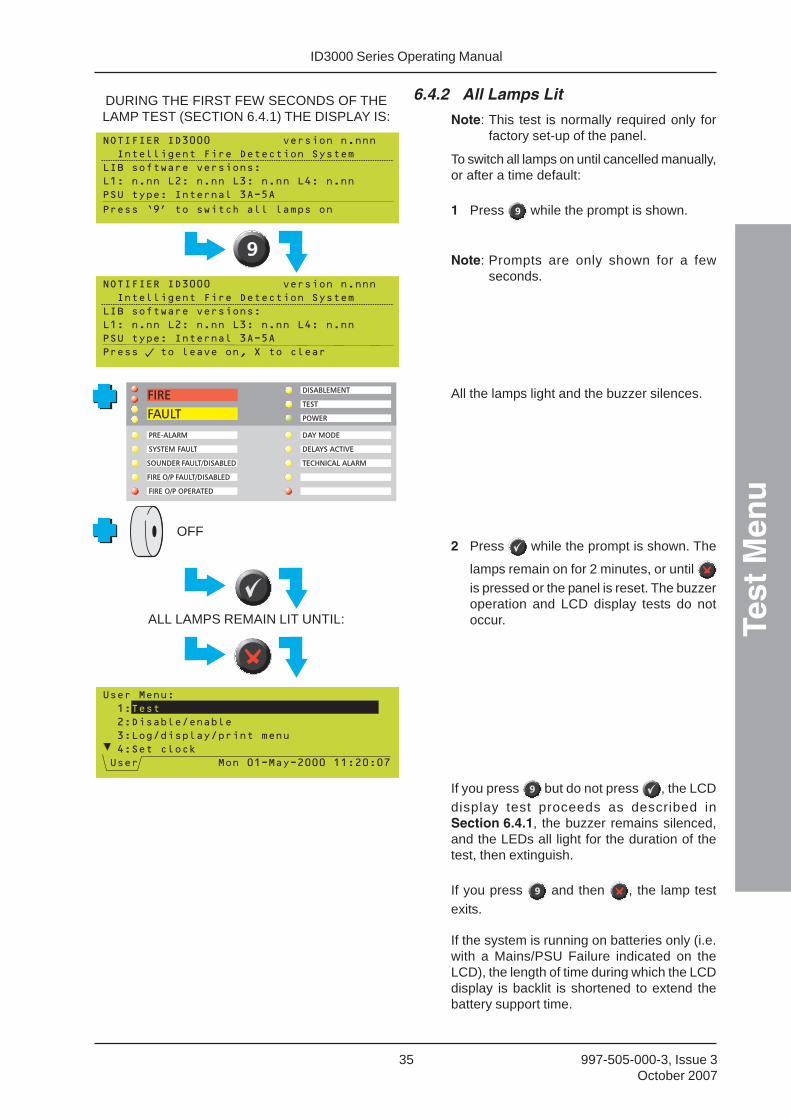
6.4.2 All Lamps Lit
Note: This test is normally required only forfactory set-up of the panel.
To switch all lamps on until cancelled manually,or after a time default:
1 Press while the prompt is shown.
Note: Prompts are only shown for a fewseconds.
All the lamps light and the buzzer silences.
2 Press while the prompt is shown. The
lamps remain on for 2 minutes, or until is pressed or the panel is reset. The buzzeroperation and LCD display tests do notoccur.
If you press but do not press , the LCDdisplay test proceeds as described inSection 6.4.1, the buzzer remains silenced,and the LEDs all light for the duration of thetest, then extinguish.
If you press and then , the lamp testexits.
If the system is running on batteries only (i.e.with a Mains/PSU Failure indicated on theLCD), the length of time during which the LCDdisplay is backlit is shortened to extend thebattery support time.
DURING THE FIRST FEW SECONDS OF THELAMP TEST (SECTION 6.4.1) THE DISPLAY IS:
ALL LAMPS REMAIN LIT UNTIL:
OFF
DAY MODEDAY MODE
DELAYS ACTIVEDELAYS ACTIVE
TECHNICAL ALARMTECHNICAL ALARM
FIRE O/P OPERATEDFIRE O/P OPERATED
PRE-ALARM
SYSTEM FAULTSYSTEM FAULT
SOUNDER FAULT/DISABLED
FIRE O/P FAULT/DISABLED
FIRE
FAULT
DISABLEMENT
TEST
POWER

ID3000 Series Operating ManualTe
st M
enu
36997-505-000-3, Issue 3October 2007
6.5 Sensor Automatic Test
Note: This is a maintenance facility only. If youinitiate a zone walk test (as describedin Section 6.2), or if a FIRE is detectedelsewhere in the system, while theautomatic test is in progress, that testis automatically cancelled if soconfigured.
This option is only available if the panel isalready configured to perform this test dailyor weekly (it cannot be configured withboth) at a programmed time of day. The testdiffers from the normal walk test in that no partof the panel is taken off watch for more than afew seconds, and no operator intervention isnormally required unless a fault is detected.
There is normally no need to force the panelto undergo this test ahead of the scheduledtime, but if you need to do so then select theconfigured test from the Test menu.
Note: This test does not apply to gas sensors.
The Test tab is displayed while the test is inprogress. It provides information about thedevice currently under test.
6.6 Replace VIEW Sensor
This option is only available if there areVIEW sensors installed on the loops. Thismenu option prompts for an access level 3passcode. It is not available to the operator.
OR
(EXAMPLE ASSUMES‘WEEKLY’)

ID3000 Series Operating Manual
Dis
able
/En
able
Men
u
37 997-505-000-3, Issue 3October 2007
7 Disable/Enable Menu
7.1 Introduction
It is possible to disable/enable:
a. The inputs for a complete zone (seeSection 7.2).
b. The outputs for a complete zone (seeSection 7.3).
c. An individual device (see Section 7.4).
7.1.1 Indications
The following indications are given if a deviceis disabled:
a. The lamp indication [DISABLEMENT lampand ZONE lamp (if appropriate)] and thepresence of a DISABLE tab show whetherany devices are disabled on the system asa whole.
b. Additional lamp indications are given forsounder and fire output disablements.
c. The fault buzzer sounds intermittently(every 2 minutes or as configured). Thismode cannot be completely silenced evenby pressing RESET (the condition is latched).
Note: In the case of a Network Master panel,these indications are shown if any panelof the network has devices disabled, notjust devices attached directly to theMaster panel. On the Slave panels,however, the indication of disablementis shown only if devices attached to thepanel itself are disabled.
Note: Depending upon the panelconfiguration, devices are identifieduniquely either by loop number anddevice address (Ln Snn or Ln Mnn,where L=loop, S=sensor, M=module) orby zone number and reference number(nnnn/nn).

ID3000 Series Operating ManualD
isab
le/E
nab
le M
enu
38997-505-000-3, Issue 3October 2007
ALL INPUTS ARE DISABLED,DISABLE TAB IS DISPLAYED ANDDISABLEMENT LED ILLUMINATES
7.2 Disable/Enable Inputs
It is possible to:
a. Disable or enable all input devices in a zonein one operation.
b. Disable all sensors in a zone in oneoperation.
To access these options, first display theDisable/Enable Menu.
Select the required zone range from the Selectfirst ZONE and Select last ZONE displays. Allselected zones are highlighted. If only onezone is required, the first and last zoneselections must be identical.
7.2.1 Disable All Input Devices
1 Select the zone as described inSection 7.2, then select the Disable AllInputs option.
Note: If a zone contains a mixture of AUX(non-alarm) modules and alarm inputs,only the alarm inputs are disabled. If,however, the zone contains only AUXmodules then all the AUX modules aredisabled.
2 The Disable tab is displayed. Use
CHANGE TABS and then the and pushbuttons to display information aboutthe disabled devices.

ID3000 Series Operating Manual
Dis
able
/En
able
Men
u
39 997-505-000-3, Issue 3October 2007
7.2.2 Disable All Sensors
This is similar to the procedure to disable allinputs, but only the sensors are disabled.However it is only available for a single zone(i.e. not if a range of zones is selected) and ifthe panel is configured to use local zones (i.e.not network zones).
7.2.3 Enable All Input Devices
Select the Enable all inputs option. If there arealready any disablements active (i.e. theDisable tab is present and the DISABLEMENTLED is lit), this option is highlightedautomatically.
ALL SENSORS ARE DISABLED,DISABLE TAB IS DISPLAYED ANDDISABLEMENT LED ILLUMINATES
DISABLEMENTS ARE CANCELLED,DISABLE TAB IS REMOVED AND
DISABLEMENT LED EXTINGUISHES

ID3000 Series Operating ManualD
isab
le/E
nab
le M
enu
40997-505-000-3, Issue 3October 2007
ALL SOUNDERS ARE DISABLED,DISABLE TAB IS DISPLAYED AND
DISABLEMENT AND SOUNDER FAULT/DISABLED LEDS ILLUMINATE
DISABLEMENTS ARE CANCELLED,DISABLE TAB IS REMOVED
DISABLEMENT AND SOUNDER FAULT/DISABLED LEDS EXTINGUISH
7.3 Disable/Enable Outputs
It is possible to:
a. Disable or enable all control modules in azone in one operation.
b. Disable or enable all sounders in a zone inone operation.
To access these options, first display theDisable/Enable Menu.
If the panel is on a Master/Slave network anduses network zones, the option ‘All OutputsAll Panels’ is provided. It has the same effectas selecting ‘Alarm Outputs by Zone’ and thenselecting ‘All Zones’. If the panel uses localzones, only one panel can be disabled at atime.
Select the required zone range from the Selectfirst ZONE and Select last ZONE displays, ORselect ALL ZONES. If only one zone is required,the first and last zone selections must beidentical.
Note: ALL ZONES also selects the internalsounder/relay circuits 1-4.
7.3.1 Disable/Enable All Sounders
1 Select the Disable Sounders option. Todisable the sounders, select option 1.
Note: Illustration shows the display when ALLZONES is selected. If only specificzones are selected, the display showsthe current zone(s), e.g. ZONES 1 to 2on the top line. If ALL ZONES isselected, the internal sounder circuitsare included but the internal relaycircuits are not included.
2 Use CHANGE TABS to view details of thedisabled devices, as described inSection 7.2.1.
3 To enable the sounders, repeat theprocedure and select option 3.
Note: If a sounder is disabled, it does notactivate in the event of an Alarm orEvacuate operation, even if the panelconfiguration specifies that it is requiredto do so.
Note: Sounder circuits will not be disabled ifthey are configured as a Fire output.

ID3000 Series Operating Manual
Dis
able
/En
able
Men
u
41 997-505-000-3, Issue 3October 2007
7.3.2 Disable/Enable All ControlOutputs
1 Select the Disable Control Outputs option.To disable the outputs, select option 2.
Note: Illustration shows the display when ALLZONES is selected. If only specificzones are selected, the display showsthe current zone(s), e.g. ZONES 1 to 2on the top line. If ALL ZONES isselected, the internal relay circuits areincluded but the internal sounder circuitsare not included.
2 Use CHANGE TABS to view details of thedisabled devices, as described inSection 7.2.1.
3 To enable the outputs, repeat the procedureand select option 4.
Note: Relay circuits will not be disabled if theyare configured as a Fire output.
DISABLEMENTS ARE CANCELLED,DISABLE TAB IS REMOVED
DISABLEMENT LED EXTINGUISHES
ALL CONTROL OUTPUTS ARE DISABLED,DISABLE TAB IS DISPLAYED ANDDISABLEMENT LED ILLUMINATES

ID3000 Series Operating ManualD
isab
le/E
nab
le M
enu
42997-505-000-3, Issue 3October 2007
7.4 Individual Device
It is possible to disable a sensor, module orsounder/relay circuit to avoid unwantedoperation where exceptional circumstancesprevail.
7.4.1 Sensor
The sensor conditions continue to bemonitored, but a detected FIRE condition doesnot lead to Fire Alarm actions being taken. Inaddition certain FAULTs (in particular devicemissing and low data reading) do not lead tonormal Fault action being taken.
To disable or enable an individual sensor:
1 From the Disable/Enable Menu, select theIndividual Device option.
2 Select SENSOR.
3 Select the zone to which the sensor isallocated - gives a list of sensors in the zone(or select ANY Zone to view details of allsensors).
4 Select the required sensor from thedisplayed list. Either:
a. Move the highlight to the required device,or
b. Use the numeric keysto enter the loopnumber and then thedevice number (thedevice nearest innumber to that typed isthen highlighted).
Note: While a device is highlighted, press to display its type and value
(continuously updated). Press to re-display the device description.
5 If the sensor is currently ENABLED, theoption is provided to DISABLE it (see left);if it is currently DISABLED, the option isprovided to ENABLE it (see below).
6 While the sensor is disabled, use CHANGETABS to view details of the disabled device.
SENSOR IS DISABLED,DISABLE TAB IS DISPLAYED ANDDISABLEMENT LED ILLUMINATES
ID3000 Series Operating Manual
Dis
able
/En
able
Men
u
43 997-505-000-3, Issue 3October 2007
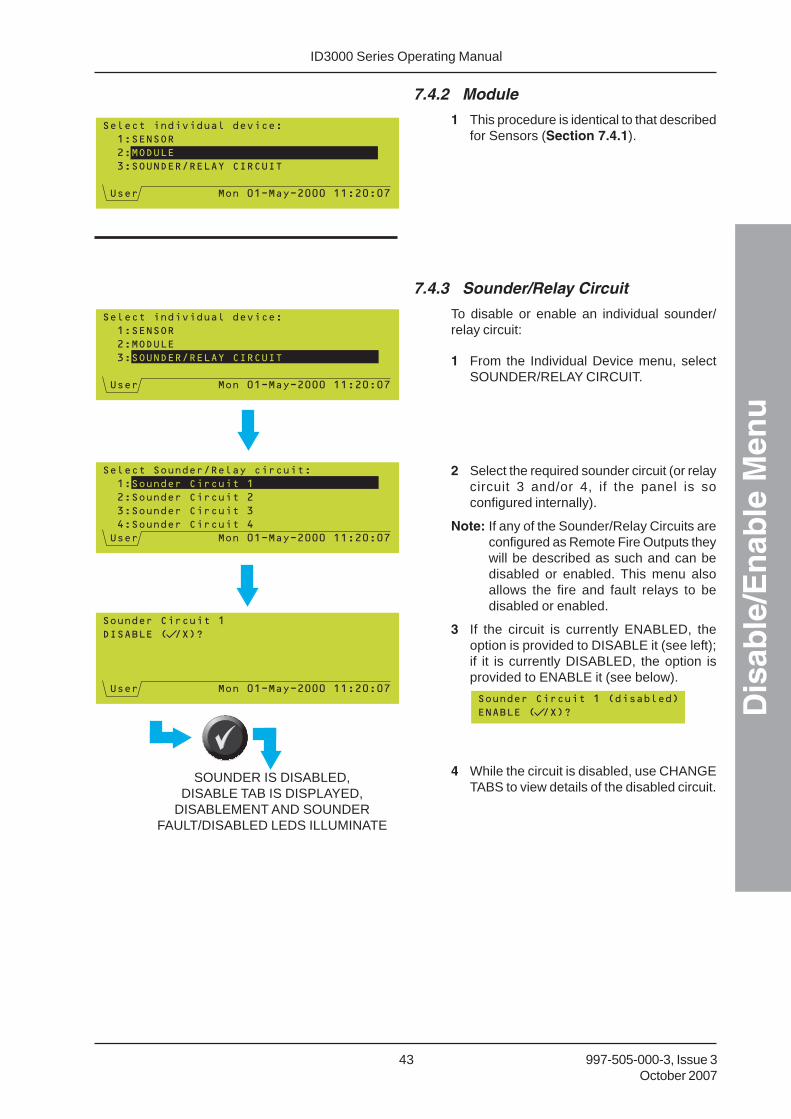
7.4.2 Module
1 This procedure is identical to that describedfor Sensors (Section 7.4.1).
7.4.3 Sounder/Relay Circuit
To disable or enable an individual sounder/relay circuit:
1 From the Individual Device menu, selectSOUNDER/RELAY CIRCUIT.
2 Select the required sounder circuit (or relaycircuit 3 and/or 4, if the panel is soconfigured internally).
Note: If any of the Sounder/Relay Circuits areconfigured as Remote Fire Outputs theywill be described as such and can bedisabled or enabled. This menu alsoallows the fire and fault relays to bedisabled or enabled.
3 If the circuit is currently ENABLED, theoption is provided to DISABLE it (see left);if it is currently DISABLED, the option isprovided to ENABLE it (see below).
4 While the circuit is disabled, use CHANGETABS to view details of the disabled circuit.
SOUNDER IS DISABLED,DISABLE TAB IS DISPLAYED,
DISABLEMENT AND SOUNDERFAULT/DISABLED LEDS ILLUMINATE

ID3000 Series Operating ManualD
isab
le/E
nab
le M
enu
44997-505-000-3, Issue 3October 2007
7.4.4 Virtual Points
Additional options to disable Virtual Input andOutput points are available provided that thepoints are configured in a zone and, for Outputpoints, that the fire panel is connected to thirdparty equipment in Voice Alarm System mode.
1 Select the required zone and point. Use thepanel’s pushbuttons in the same manneras described in Section 7.4.1.
Note: The Virtual Input or Output Point text isdisplayed beside each point; press the
button to display the zone number(if there is no text configured the zonenumber is always displayed).
2 Select DISABLE (or ENABLE).
7.5 Delayed Sounders Mode
If the panel has been configured with sounderdelays (Section 7.6.2.2 of the ID3000 SeriesPanel Configuration Manual), an additionaloption is displayed on the Disable/Enablemenu.
Select whether sounders are to operateimmediately upon alarm, or whether they areto operate after their configured delay.
This display only occurs when there are no tabspresent.
IF DELAYED IS SELECTED,STATUS DISPLAY IS:
MAKE SELECTION
������������ ��������
��������
�����������������������
��
�!�"�� ���#���$%��
�&�"�����������'��(�)*��)�++ �((��+�+,
!�"�� �����#���$%��
-"%.�/������������������0����1����2
��0%�3%����4���5��2
�6�- ��%"7�&���
�(������"��&� "�
�&�"�����������'��(�)*��)�++ �((��+�+,
����/%�
!�"�� �����#���$%������0����1����2
8��#� 9�"�" �9
(���%� �����3%�����(��:���
(��* ��%"�"%%.
�&�"�����������'��(�)*��)�++ �((��+�+,
;������1
!�"�� �����#���$%������0����1����2
8��%� �����3%����6+��:���
(���%� �����3%�����(��:���
(���%� �����3%���((+��:���
�&�"�����������'��(�)*��)�++ �((��+�+,
;��%� �����3%�����(��:���
!�"�� �����#���$%���8
�#� 9�"�" �9
�%� �����/%��6+
��""���7����:���������:���0��<2=
'��(�)*��)�++ �((��+�+,
�%��"&�������������+)�%�)�++;�((��+�+,

ID3000 Series Operating Manual
Dis
able
/En
able
Men
u
45 997-505-000-3, Issue 3October 2007
TO DISABLE AN INPUT ZONE AT ANOTHERPANEL:SELECT THE PANEL
SELECT THE ZONE
SELECT ENABLE OR DISABLE
7.6 Network Disable and Enable
This additional information applies only if thepanel is part of a Master/Slave network. Itdescribes how to:
a Disable/enable a complete input zone on adifferent panel on the network.
b Disable/enable a specified device on adifferent panel on the network.
Note: If panel is part of an ID2net and localzones are used, they are selected bypanel followed by zone number. Ifnetwork zones are used, they areselected by network zone number only.
7.6.1 Input Zone
To disable or enable an input zone on thenetwork, first select ‘Alarm Inputs by Zone’ (seeSection 7.2), then:
1 Select the panel. The * and initial cursorposition indicate the local panel. The *remains fixed in position, the cursor ismovable.
2 Select the zone (in this example the zoneis at the Slave 1 panel). This is a numericentry.
3 Either ENABLE or DISABLE the selectedzone. A WAIT message is displayed whilethe selection is transmitted over thenetwork.
The Remote Panel Disablement display is thenshown.
IF DISABLE SELECTED

ID3000 Series Operating ManualD
isab
le/E
nab
le M
enu
46997-505-000-3, Issue 3October 2007
7.6.2 Device
To disable or enable an individual device onthe network:
1 Select the panel.
2 Select the device. When selecting a deviceover the network it is not possible to scrollthrough a list of device; you must enter theloop number and address when prompted.You cannot select remote sounder or relaycircuits.
3 Either ENABLE or DISABLE the selecteddevice.
The Remote Panel Disablement display is thenshown.
TO DISABLE A DEVICE AT ANOTHER PANEL:SELECT THE PANEL
SELECT THE TYPE OF DEVICE, THE LOOP IT ISON, AND ITS ADDRESS ON THE LOOP
SELECT ENABLE OR DISABLE
IF DISABLE SELECTED

ID3000 Series Operating Manual
Dis
able
/En
able
Men
u
47 997-505-000-3, Issue 3October 2007
7.7 Disable/Enable via Remote Switch
This function is only available if a remote switchis connected to a loop module which has beenconfigured as an AUXILIARY type input, andthis has been linked to a DISABLE operationon a particular zone or zones. See the ID3000Series Panel Configuration Manual(997-506-XXX) for details on how to configurethis option.
The function enables the use of a remotely-placed switch to disable and enable allsensors, or all inputs, or all inputs and outputs(depending upon the panel configuration)without the need for access to the panel.Control of individual devices is not possible bythis means.
Operate the switch as indicated to disableinputs/outputs according to the pre-configuredset-up. If the switch contains, or is adjacentto, an indicator lamp, this should light up whenthe disable operation has been completed.Release the switch to restore the inputs/outputs to normal.
7.8 Time-of-Day Control and Override
Using the time-of-day function, input devicescan be disabled and enabled as part of thepanel configuration set up.
There is normally no time-out for disableddevices; the disablement is effectivelypermanent until cancelled by a subsequentenablement operation. Some systems,however, may be configured so thatdisablements are automatically cancelled aftera set time-out or at certain times of the day(non-EN54 compliant). This is set up duringpanel configuration - refer to Sections 7.7, 9and 11.7 of the ID3000 Series PanelConfiguration Manual (997-506-XXX).
Note: You cannot have different zones set todifferent time-of-day schedules.
If time-of-day control has been configured fordisablements (or for other panel functions, e.g.sensor sensitivity), an additional option - ‘Time-of-day Program Over-ride’ is available on theUser menu. To override the time-of-day control,select the ‘OVER-RIDE SET’ option - the panelbehaviour reverts to that outside of the currenttime period. OVER-RIDE NOT SET re-instatesthe current period’s behaviour.
EN54-2 : 9.5. Time-of-Day cancellation of
disablements must not beconfigured
TO OVER-RIDE A TIME OF DAY PROGRAM:
MAKE SELECTION
ID3000 Series Operating ManualL
og
/Dis
pla
y/P
rin
t M
enu
48997-505-000-3, Issue 3October 2007
8 Log/Display/Print Menu
8.1 Introduction
The Display/Log/Print Menu provides thefollowing options:
a. Display and or logging of device data (seeSection 8.2).
b. Printing of device data (see Section 8.3).
c. Display and reprint of the event log (seeSection 8.4).
d. Control of the printer mode, if a PRN-ID orP40 40-column printer is configured (seeSection 8.5).
All printing options only work if a printer isinstalled.
Note: Depending upon the panelconfiguration, devices are identifieduniquely either by loop number anddevice address (Ln Snn or Ln Mnn,where L=loop, S=sensor, M=module) orby zone number and reference number(nnnn/nn).
ID3000 Series Operating Manual
Lo
g/D
isp
lay/
Pri
nt
Men
u
49 997-505-000-3, Issue 3October 2007
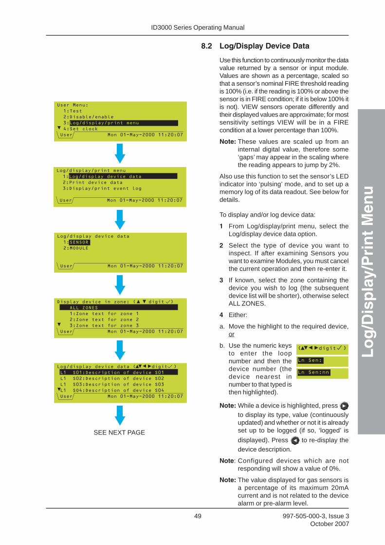
8.2 Log/Display Device Data
Use this function to continuously monitor the datavalue returned by a sensor or input module.Values are shown as a percentage, scaled sothat a sensor’s nominal FIRE threshold readingis 100% (i.e. if the reading is 100% or above thesensor is in FIRE condition; if it is below 100% itis not). VIEW sensors operate differently andtheir displayed values are approximate; for mostsensitivity settings VIEW will be in a FIREcondition at a lower percentage than 100%.
Note: These values are scaled up from aninternal digital value, therefore some‘gaps’ may appear in the scaling wherethe reading appears to jump by 2%.
Also use this function to set the sensor’s LEDindicator into ‘pulsing’ mode, and to set up amemory log of its data readout. See below fordetails.
To display and/or log device data:
1 From Log/display/print menu, select theLog/display device data option.
2 Select the type of device you want toinspect. If after examining Sensors youwant to examine Modules, you must cancelthe current operation and then re-enter it.
3 If known, select the zone containing thedevice you wish to log (the subsequentdevice list will be shorter), otherwise selectALL ZONES.
4 Either:
a. Move the highlight to the required device,or
b. Use the numeric keysto enter the loopnumber and then thedevice number (thedevice nearest innumber to that typed isthen highlighted).
Note: While a device is highlighted, press to display its type, value (continuouslyupdated) and whether or not it is alreadyset up to be logged (if so, ‘logged’ is
displayed). Press to re-display thedevice description.
Note: Configured devices which are notresponding will show a value of 0%.
Note: The value displayed for gas sensors isa percentage of its maximum 20mAcurrent and is not related to the devicealarm or pre-alarm level.
SEE NEXT PAGE

ID3000 Series Operating ManualL
og
/Dis
pla
y/P
rin
t M
enu
50997-505-000-3, Issue 3October 2007
Note: If an alarm condition exists, the followingdisplays are not available below accesslevel 3 because there is insufficientspace on the display.
5 For sensors and input modules, you can selectthe LED mode. OFF means either not-illuminated or ‘blinking’, if the panel is configuredto do this in normal polling. Select the otheroptions to enable a device to be easily identified.
For analogue sensors only, the data readingfrom the device can be stored in a data log atregular time-intervals (intended for use withthe ID3000 Series support tool which runs onan IBM-compatible PC):
6 Use and to step between differentsensors in the selected zone. The analoguedata and VIEW processing data areconstantly updated (VIEW data is onlypresent if the device is a VIEW sensor. Vais an average used for drift compensationand is normally approx. 25% - at the limits5%-35% the sensor is in a fault condition.Vs indicates the sensor alarm condition,corrected for drift compensation).
Note: Press from this display to view agraphical representation of the sensor’sanalog output plotted against time,provided that a log of at least 240 sampleshas been set up as given in step 7. Furtherinformation is given in Section 8.2.1.
7 To set up a log, enter the number of datavalues (i.e. samples) to be stored (up to4000 if no other sensors are currently beinglogged, otherwise may be less). You mustuse the numeric pushbuttons to do this; if
you press the , , or pushbuttons the panel displays themessage ‘Press a digit to amend log’.
Note: Up to 22 sensors may be loggedsimultaneously, with a combined total ofup to 20000 values stored at a time.When the log is full, logging continuesfor each sensor with the oldest databeing over-written.
8 Enter the required recording interval; awhole number of seconds, in the permittedrange 1 to 16,000 (just under four and ahalf hours).
9 Confirm the entries.
FROM PREVIOUS PAGE
(SENSORS ONLY -SELECT OPTION, THEN)
NUMERICENTRY
+ NUMERICENTRY
(SENSORS ANDINPUT MODULES
ONLY)
SEE NEXT PAGE

ID3000 Series Operating Manual
Lo
g/D
isp
lay/
Pri
nt
Men
u
51 997-505-000-3, Issue 3October 2007
10 The data log is then displayed. To cancellogging for the current device, enter 0samples and then confirm the cancellation.
8.2.1 Analog Graphical Display
Press from this display to view a graphicalrepresentation of the sensor’s analog outputplotted against time, provided that a log of atleast 240 samples has been set up asdescribed in Section 8.2 (step 7).
a. If the log is not set up following message isdisplayed: ‘Need to set up data log with atleast 240 samples before plotting a graph.’.
b. If the log is set up, the graphicalrepresentation is displayed.
The most recent event is at the right of thedisplay (if insufficient time has elapsed sincethe log was set up, the left side of the displaymay have a blank area). The data below thegraph alternates every 2 seconds between thedevice description and the start and end timesof the graph (together with some pushbuttonfunction information). If the start time is morethan 24 hours previous, it is shown as numberof days (e.g. 01.66d) instead of hh:mm:ss.
The solid line and dotted lines represent thedevice’s alarm and pre-alarm thresholdsrespectively.
Use the and arrows to scroll throughthe display, i.e to show earlier or later times.
Use the and arrows to increase ordecrease the scale, i.e to show shorter orlonger time periods. The maximum zoom issuch that one sample equals one pixel, thusthe displayed time period is dependant uponthe sample rate.
Press the ‘ ‘ pushbutton to exit the graphicalrepresentation and return to the log display.
Note: If a PRN-ID printer is installed (and notin HOLD or DISABLE mode), thenbefore the log is re-displayed the optionto print the graph is provided. This facilityis not available for any other type ofprinter.
FROM PREVIOUS PAGE
������������ �������� �
������������������������������
�� ���!�����"�����#�$��
%�� �����������&���$'()��($�������$���'
������������ �������� �
�'����$*����#�����#+��,�����'����$*
��-�. �"/� ��0��&10
2�3,45
&���$'()��($�������$���'

ID3000 Series Operating ManualL
og
/Dis
pla
y/P
rin
t M
enu
52997-505-000-3, Issue 3October 2007
�*�����6��� ������7 �� �
��������������8�19����������:���!!�-
8�19�" �����!��8��#���;���8��#�($;��
��
$��!��6��&<1���� �
%�� �����������&���$'()��($�������$���'
�!�0=9��� �
�*�����6��� ������7 �� �
��������������8�19����������:���!!�-
8�19�" �����!��8��#���;���8��#�($;��
�� ���!�����"����#����
�� ���!��� � ����#����2�� /�-4
%�� �����������&���$'()��($�������$���'
8.2.1.1 VIEW Sensors
From the log display, an additional menu is
provided for VIEW sensors when ispressed. Select either:
a. Raw Data - the graph then shows the datareceived from the VIEW sensor.
b. Smoothed Data - the graph then shows lessdetail, i.e. a less spiky display.
It is not possible to log both raw and smoothsimultaneously on the same sensor.
Because VIEW sensors use a co-operativesensing algorithm, they will not necessarily gointo an alarm or pre-alarm state when thegraph shows the data above these thresholds.
The log display then shows ‘(Smoothed)’ forsmoothed data, or blank for raw data.

ID3000 Series Operating Manual
Lo
g/D
isp
lay/
Pri
nt
Men
u
53 997-505-000-3, Issue 3October 2007
8.3 Print Current Device Data
Use this option to obtain a complete or partialprintout of all the devices on the system,including current readings and status.
To obtain a printout:
1 From the Log/display/print menu, select thePrint Device Data option.
2 Select the required zone or ALL ZONES.
3 Select whether selective printing of onlythose devices with an unusually highreading is required. Either key in the desiredminimum value (expressed as a
percentage) followed by , or press just
to select the default of ALL values. Innormal conditions values should be below60%.
4 If you select the default of ALL values, youcan select whether only disabled devicesare to be printed. If you select yes and thepanel is the Master Panel on a Networksystem, any disabled devices connected tothe Slave panels are also printed (this isthe only case in which a list of devices atanother panel can be obtained). Theprintout will list, in addition to configurationdetails about each device and its currentreading, indications of any device that isdisabled and any device that is MISSING(i.e. registering a NO-REPLY fault). ID2netnetwork zones: options allow printing of alldevices in zone or panel (but not network).
5 For all cases (i.e. whether or not steps 3and 4 applied), select the type(s) of deviceto be printed.
To abort the printout, press .
Note: The printout will also be aborted if anynew alarm occurs in the meantime.
(‘ALL ZONES’ONLY)
(IF ‘ALL’ AND THEREARE DISABLED
DEVICES)
PRINTING BEGINS
(‘ALL’ ANDDISABLEDDEVICES)

ID3000 Series Operating ManualL
og
/Dis
pla
y/P
rin
t M
enu
54997-505-000-3, Issue 3October 2007
8.4 Display/Re-print Event Log
This is a means of examining the most recentpast history of events on the system, up to themaximum recording depth of 600 events (oncethis capacity is reached, new events over-writethe earliest events).
To display and print the event log:
1 From the Log/display/print menu, select theDisplay/print event log option. The eventnumber (range 00000 to 65536) ishighlighted by default, and the most recent
event is shown. Use and to scrollthrough the events in sequence, backwardsand forwards in time respectively.
2 To scroll through the events by date, press
to highlight the date field and thenproceed as described for event number.The first event on that date is shown. Dateson which no events occurred are skipped.The earliest date is that of the oldest eventstill recorded in the log (as the log becomesfilled the oldest events are over-written).
3 To scroll through the events by time, press
to highlight the time field and thenproceed as described for event number.You step approximately one hour at a time;hours in which no events occurred are
skipped. Press again to re-highlight theevent number. Steps 1 to 3 can be repeatedas many times as required.
4 Events are printed out at time of occurrence(unless the printer is disabled) as describedin Section 8.3. You can re-print a selectionof all recorded events spanning any timeperiod. Display the first event you wish tore-print and confirm the selection.
5 Display the last event you wish to re-print
and confirm the selection. If you press twice without changing anything, a singleevent is printed.
Note: When any portion of the event historyis re-printed, the original sequencenumbers of the re-printed events arealso reproduced. This enables you todetermine where the re-printed dataends and ‘l ive’ event loggingre-commences.
RE-PRINTING BEGINS

ID3000 Series Operating Manual
Lo
g/D
isp
lay/
Pri
nt
Men
u
55 997-505-000-3, Issue 3October 2007
8.5 Printer Control Modes
This display is only available if a PRN-ID orP40 40-column printer is configured.
To set the mode:
1 From the Log/display/print menu, select thePrinter Control option.
2 Select the required printer control mode:
a. Normal. This mode is always selectedby default when the panel is poweredup.
b. Hold. The printout data is held inmemory but not printed.
c. Disable. The printout data isdiscarded.
8.5.1 Mains FailureDuring panel mains failures, the printer statusis equivalent to being in ‘Hold’ mode. However,if the printer is manually set to ‘Hold’, it doesnot revert to normal when the mains isrestored.

ID3000 Series Operating ManualS
etti
ng
th
e C
lock
56997-505-000-3, Issue 3October 2007
9 Setting the Clock
Use this menu option after any Time Zonechange, e.g. start/end of British Summer Time(if not configured for auto-adjust), and afterthe system has been fully powered-off (in thelatter case the system will start-up at midnighton the last date on which it had been operating,or at the time when the clock was last reset,whichever was the later).
To set the clock:
1 Display the Setting Clock screen. The clockdisplay will be ‘frozen’, with the last digit ofthe seconds field highlighted.
2 To adjust the date and time, use the
and pushbuttons to move the cursor
over the field to be changed. Use the
and pushbuttons to adjust the value ofthe field to give the current date and time.
Note: The date, time and last two digits of theyear can also be entered directly usingthe numeric pushbuttons.
3 Summer Time - select one of the following:
a. NONE. Time changes must be setmanually.
b. AUTO. Time changes automatically at 2amon the days indicated on the screen.
c. DEFINED. Time changes automatically at2am on user-defined dates. Valid only forthe current year (after which the systemresets to NONE).
4 After all fields have been adjusted correctly,
press to start the clock running at the
precise time shown, or press to cancelthe whole operation and return to theprevious clock setting.

ID3000 Series Operating Manual
Oth
er U
ser
Men
u O
pti
on
s
57 997-505-000-3, Issue 3October 2007
10 Other User Menu Options
10.1 Alarm Count
This function displays the number of times thatthe panel has entered the alarm condition (maynot be the same as the total number of alarmevents recorded).
The User menu is re-displayed after a fewseconds.
10.2 Enter Level 3 Passcode/Configuration
Option 6 on the User menu prompts for anaccess 3 passcode, which gives access tomenu options required by commissioning andconfiguration engineers. These menu optionsare not available to the operator.
10.3 Set Language
This function selects the language used on theLCD display. The languages shown areexamples only.
IF AT ACCESS 2 VIA THE KEYSWITCH:
OR IF AT ACCESS 2 VIA THE NUMERIC KEYS:

ID3000 Series Operating ManualN
on
-lat
ched
Inp
ut
Op
erat
ion
58997-505-000-3, Issue 3October 2007
11 Non-latched Input Operation
This function enables the use of a remotely-placed switch to switch on, temporarily, certainoutputs without the need for access to thepanel. The function is only available if a remoteswitch is connected to a loop module whichhas been configured as an AUXILIARY typeinput, and this has been linked to specificoutputs in the panel configuration. For detailsof how to configure this option, see thedescription of the Control Matrix in the ID3000Series Panel Configuration Manual(997-506-XXX).
Operate the switch as indicated to cause thesounders or other outputs to operate in the pre-programmed pattern. Release the switch toswitch off the outputs.
Normally there will be no indication at the panelof these operations. However, someinstallations may be configured so that thelogging of AUX inputs occurs; if this is the case,the active AUX inputs are shown on the displaydescribed in Section 5.3.9, Auxiliary EventDisplay.
AC
ABB
C

A1 - 1 997-505-000-3, Issue 3October 2007
ID3000 Series Operating Manual
Ap
pen
dix
1 -
Lo
g B
oo
k
Appendix 1 - Log Book
In accordance with EN54 part 14, it is the user’sresponsibility to maintain a log book and torecord all events resulting from or affecting thesystem. The log book should be kept in a placeaccessible to authorised persons (preferablynear the control panel).
One or more identifiable individuals should beappointed to oversee or carry out all entries inthe log book. The names of these persons (andany changes of responsible person) should berecorded.
All events should be properly recorded (eventsinclude real and false fire alarms, faults,pre-alarm warnings, tests, temporarydisconnections and service visits). A brief noteof any work completed or outstanding shouldbe made.
Sample pages of the log book are providedhere and can be photocopied to produce a logbook that conforms to EN54 part 14. Thesample below is for the reference data (e.g.the name of the responsible person), while thesample on the next page is for the entry ofevent data.
REFERENCE DATA
Name and address
Responsible person Date
Date
Date
Date
The system was installed by
and is maintained under contract by
until
Telephone number
should be contacted if service is required.
ID3000 Series Operating ManualA
pp
end
ix 1
- L
og
Bo
ok
A1 - 2997-505-000-3, Issue 3October 2007
EVENT DATA
Date Time Event Action required Date Initialscompleted

local distributorEvery care has been taken in the preparation of this document but no liability can be accepted for the use of the information therein. Design features may be changed or amended without prior notice.
Quality Systems Certificate No. 154Assessed to ISO9001
LO
SS
PR
EV
EN
T
ION
CERTIFICAT
ION
BO
A
RD
007
Charles AvenueBurgess HillW. SussexRH15 9UF
T: +44 (0) 1444 230 300F: +44 (0) 1444 230 888E:[email protected]