Embed Size (px)
Citation preview

ID50/60installation,
commissioning &
configuration
manual
997-263-000-13, Issue 13 October 2010
ID50 Series Panel - Installation, Commissioning & Configuration Manual
Co
nte
nts
i 997-263-000-13, Issue 13October 2010
Contents
1 Introduction 1
1.1 Manual Purpose 1
1.2 System Design and Planning 1
1.3 General 2
1.3.1 Date-dependent Functions 2
1.4 CE Marking 2
1.5 EN54 Functions 3
1.6 Ancillary Functions 4
1.7 Related Documents 5
1.8 Warnings and Cautions 5
1.9 Tips 5
1.10 Glossary of Icons 6
2 Installation Guide 7
2.1 How to Use this Section 7
2.2 Pre-Installation Check List 7
2.1.1 Some Panel DO’s and DON’T’s 7
2.3 Transient Protection 8
2.4 Product Inspection 9
2.4.1 Checking Your Panel for Damage 9
2.4.2 What to do if Panel is Damagedor Suspect 10
2.5 Dismantling the Panel 11
2.5.1 Removing the Cover 11
2.5.2 Removing the Panel Electronics 12
2.5.3 Back Box Fixing 13
2.5.4 Semi-Flush Mounting Bezel (Optional) 14
2.6 Assembling the Panel 15
2.7 RS485 Communications Link 16
2.7.1 Fitting the RS485 Interface Module PCB17
2.8 RS232 Interface Connections 18
3 Cabling 19
3.1 Cabling Instructions 19
3.1.1 Cable Terminations 20
3.2 Cabling Installation Notes 21
3.2.1 Introduction 21
3.2.2 Quality of Cable and of Cable Installation 21
3.3 EMC Considerations 22
ID50 Series Panel - Installation, Commissioning & Configuration ManualC
on
ten
ts
ii997-263-000-13, Issue 13October 2010
3.3.1 Screen Termination 22
3.3.2 Ferrite Sleeves (Optional) 22
3.4 MICC Cables 22
4 Commissioning 23
4.1 Introduction 23
4.2 Preliminary Checks 23
4.3 Internal Checks 24
4.3.1 Jumper Link Options 24
4.4 External Wiring Checks 25
4.4.1 Loop Wiring 26
4.4.2 RS485 Communications Link 27
4.4.3 DC Auxiliary Output 27
4.4.4 Sounder Circuit Outputs 28
4.4.5 CFG Outputs C and D 30
4.4.6 -VE Outputs 31
4.4.7 Digital / ÜE Inputs 31
4.4.8 Switch Connections 31
4.5 Powering the Panel 32
4.5.1 Start-up Language Selection 32
4.5.2 Batteries 33
4.6 Configuration and Handover 34
4.7 Commissioning Tests 35
4.7.1 Test LEDs 35
4.7.2 Test LCD 35
4.7.3 Test Zones 35
4.7.4 Test Auto High Test 35
4.7.5 Test Outputs 35
4.7.6 Test Buzzer 35
4.7.7 Test Keyboard 35
4.8 Sensors and Modules 36
4.8.1 EN54 Requirements 36
4.8.2 Loop Wiring Testing 36
5 Configuration 37
5.1 Introduction 37
5.2 Navigation and Number Entry 37
5.3 Level 2 Configuration Options 37
5.4 Level 3 Configuration Options 38
5.5 Setup Options 39
5.5.1 Panel Options 39
ID50 Series Panel - Installation, Commissioning & Configuration Manual
Co
nte
nts
iii 997-263-000-13, Issue 13October 2010
5.5.2 Site Details 46
5.5.3 Device Options 47
5.5.4 Peripheral Options 55
5.5.5 Day/Night Settings 63
5.6 Circuit Options 69
5.6.1 Signalling Line Circuit (SLC) - Devices 69
5.6.2 Signalling Line Circuit (SLC) - Learn 80
5.6.3 On-Board Circuits 83
5.7 Control-By-Event Output Rules 85
5.7.1 Output Type 88
5.7.2 Filter-by-type 89
5.7.3 Evacuation 90
5.7.4 Silence 90
5.7.5 Interrupt Delay 91
5.7.6 Class Change 91
5.7.7 Two Zone 92
5.7.8 Zones 93
5.7.9 Device Inputs 94
5.7.10 Soak Timer 95
5.8 Zone Texts 95
5.9 Access Options 97
5.10 System Options 98
5.10.1 Crystal Frequency 98
5.10.2 Wipe Memory 99
5.11 Normal 99
Appendix 1 - Specification A1-1 to A1-6
Appendix 2 - ID60 Single Loop PanelDifferences A2-1 to A2-5
Appendix 3 - Fault Messages & Meanings A3-1 to A3-4
Appendix 4 - EN54-2 Options withRequirements A4-1 to A4-4
Appendix 5 - Configuration of a Fault RoutingOutput Using a Zone Monitor A5-1
ID50 Series Panel - Installation, Commissioning & Configuration Manual
Intr
od
uct
ion
1 997-263-000-13, Issue 13October 2010
1 Introduction
1.1 Manual Purpose
The purpose of this manual is to provide the user with allrecommended procedures and full technical details forthe successful installation, commissioning andprogramming of a NOTIFIER ID50 Series Panel.
The descriptions and procedures also apply to theNOTIFIER ID60 panel. Differences between the ID50 andID60 panels are given in Appendix 2.
Procedures described in this manual include appropriatewarnings and cautions to guide the user towards adoptingsafe and methodical work practices during the installation,commissioning and programming phases.
The ID50 Series panels support OPAL protocol devices.These devices support both OPAL and CLIP loop pollingprotocols so they can be added to an existing CLIPprotocol loop. However, when OPAL protocol is enabledon the loop a maximum of 40 CLIP device addressescan be supported as part of the total of 99 sensors and99 modules.
Important Note
This manual must be read, and its content clearlyunderstood, before proceeding with any work relating tothe ID50 Series Panel. Damage to the control panel mayresult from NOT following the recommended proceduresdescribed in this manual.
This manual provides all necessary instructions for theID50 Series Panel and applies only to fire panels fittedwith compatible software.
CAUTION: In particular, care must be taken whenpowering up/down any repeaters.
If there are any areas of doubt, consult your supplierbefore continuing with the system installation,commissioning and programming.
1.2 System Design and Planning
It is assumed that the system, of which the ID50 SeriesPanel equipment is a part, has been designed by acompetent fire alarm system designer in accordance withthe requirements of EN54 Part 14 and any other localcodes of practice that are applicable.
The design drawings should clearly show the positionsof all the ID50 Series Panel control equipment and fielddevices.
ID50 Series Panel - Installation, Commissioning & Configuration ManualIn
tro
du
ctio
n
2997-263-000-12, Issue 12February 2010
1.3 General
The ID50 Series Panel is designed for use withNOTIFIER’s range of addressable analogue sensors,control and monitoring modules and addressable callpoints. A unique signalling protocol is used, having digitaladdress and control signals and analogue pulse widthmonitoring for the reply data from devices.
The serial communications interface operates underRS485 protocol and enables communications betweenthe fire panel and repeaters.
While every effort is made to ensure the accuracy of thecontent of this manual, the manufacturer reserves theright to change the information without notice.
Installation
The ID50 Series Panel is easy to install providing therecommended procedures described in this manual arefollowed. To avoid inadvertent contamination of the PCBAssembly, the manufacturer recommends it be installedin the back box only after all other trades have completedtheir tasks.
Commissioning
To commission the ID50 Series Panel, follow therecommended procedures described in this manual. Themanufacturer recommends that during commissioningand maintenance, ALL RS485 signal cables aredisconnected at the Panel end, BEFORE powering downthe system and are connected AFTER powering up thesystem.
Configuration
To configure the panel and system, carefully read andfollow the procedures given in this manual. Theseprocedures describe the menus that are displayed onthe Liquid Crystal Display (LCD) Unit.
Refer to the ID50 Series Operating manual (ref: 997-264-000-X) for a description of compatible addressableSignalling Loop Circuit (SLC) analogue devices.
1.3.1 Date-dependent Functions
The calendar end date for this product is 31/12/2063(two thousand and sixty-three) and it will perform correctlyup to this date.
The calendar function has not been tested beyondthis date.
1.4 CE Marking
CE
This panel is CE Marked to show that it conforms to therequirements of the following European CommunityDirectives:
Only fit the electronicsmodule after all the other
trades have completedtheir tasks!
Only suitably-qualifiedengineers must install,
commission andconfigure this product.
ID50 Series Panel - Installation, Commissioning & Configuration Manual
Intr
od
uct
ion
3 997-263-000-13, Issue 13October 2010
The EMC Directive 2004/108/EEC, by the application ofthe following EMC Standards:
EN 61000-6-3: Electromagnetic Compatibility (EMC)Generic emission standard for Residential,Commercial and Light industrial environments
EN 50130-4: EMC Product family standard: Immunityrequirements for components of fire, intruder andsocial alarm systems.
Low Voltage Directive 2006/95/EEC, by the applicationof the safety standard:.
EN 60950-1: Safety of information technologyequipment.
The Construction Products Directive 89/106/EEC, by theapplication of the following standards:
EN 54-2:1998, (Amd. 1 & 2): Fire detection and firealarm systems - Control and indicating equipment.
EN 54-4: 1998 (Amd. 1 & 2): Fire detection and firealarm systems - Power supply equipment.
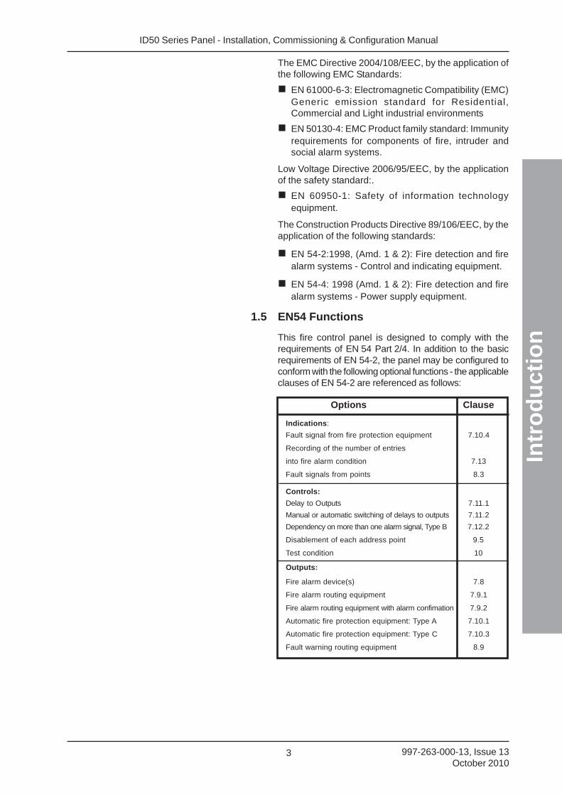
1.5 EN54 Functions
This fire control panel is designed to comply with therequirements of EN 54 Part 2/4. In addition to the basicrequirements of EN 54-2, the panel may be configured toconform with the following optional functions - the applicableclauses of EN 54-2 are referenced as follows:
Options Clause
Indications:
Fault signal from fire protection equipment 7.10.4
Recording of the number of entries
into fire alarm condition 7.13
Fault signals from points 8.3
Controls:
Delay to Outputs 7.11.1
Manual or automatic switching of delays to outputs 7.11.2
Dependency on more than one alarm signal, Type B 7.12.2
Disablement of each address point 9.5
Test condition 10
Outputs:
Fire alarm device(s) 7.8
Fire alarm routing equipment 7.9.1
Fire alarm routing equipment with alarm confimation 7.9.2
Automatic fire protection equipment: Type A 7.10.1
Automatic fire protection equipment: Type C 7.10.3
Fault warning routing equipment 8.9
ID50 Series Panel - Installation, Commissioning & Configuration ManualIn
tro
du
ctio
n
4997-263-000-12, Issue 12February 2010
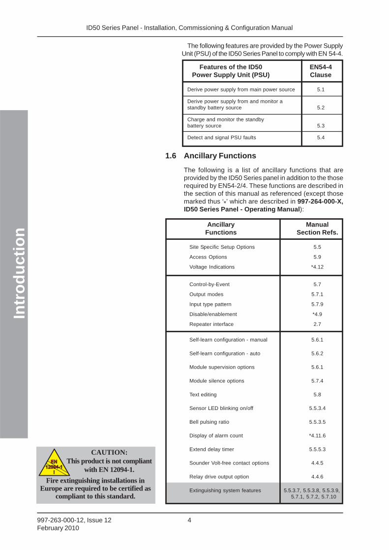
1.6 Ancillary Functions
The following is a list of ancillary functions that areprovided by the ID50 Series panel in addition to the thoserequired by EN54-2/4. These functions are described inthe section of this manual as referenced (except thosemarked thus ‘*’ which are described in 997-264-000-X,ID50 Series Panel - Operating Manual):
Ancillary ManualFunctions Section Refs.
Site Specific Setup Options 5.5
Access Options 5.9
Voltage Indications *4.12
Control-by-Event 5.7
Output modes 5.7.1
Input type pattern 5.7.9
Disable/enablement *4.9
Repeater interface 2.7
Self-learn configuration - manual 5.6.1
Self-learn configuration - auto 5.6.2
Module supervision options 5.6.1
Module silence options 5.7.4
Text editing 5.8
Sensor LED blinking on/off 5.5.3.4
Bell pulsing ratio 5.5.3.5
Display of alarm count *4.11.6
Extend delay timer 5.5.5.3
Sounder Volt-free contact options 4.4.5
Relay drive output option 4.4.6
Extinguishing system features 5.5.3.7, 5.5.3.8, 5.5.3.9,5.7.1, 5.7.2, 5.7.10
CAUTION:This product is not compliant
with EN 12094-1.EN
12094-1
!
EN
12094-1
!
Fire extinguishing installations inEurope are required to be certified as
compliant to this standard.
The following features are provided by the Power SupplyUnit (PSU) of the ID50 Series Panel to comply with EN 54-4.
Features of the ID50 EN54-4Power Supply Unit (PSU) Clause
Derive power supply from main power source 5.1
Derive power supply from and monitor astandby battery source 5.2
Charge and monitor the standbybattery source 5.3
Detect and signal PSU faults 5.4

ID50 Series Panel - Installation, Commissioning & Configuration Manual
Intr
od
uct
ion
5 997-263-000-13, Issue 13October 2010
1.7 Related Documents
This manual only describes the installation,commissioning and configuration of the ID50 SeriesPanel. All operating functions are covered by the:
ID50 Series Panel Operating Manual (ref:997-264-000-X)
The Panel can support repeaters via the RS485communications link. This manual does not providedetails about the repeaters or Compact Mimics; theseare described in:
IDR-2A, -2P & -6A Repeaters User Manual(ref: 997-411-000-X).
IDR Mimic Installation and Commissioning Manual(ref: 997-412-000-X).
Compact Mimic Installation Instructions (ref. 997-497-000-X).
Note: The ‘000’ part of the manual reference is the UKcountry code for the manual.
The ID50 Panel can also support the VIEWTM sensor. Thismanual does not attempt to cover all the VIEWTM sensorprogramming and calibration issues as these aredescribed in some detail in the following, which is availablefrom NOTIFIER’s Technical Support Department:
VIEWTM Application Guide (ref: 997-198).
1.8 Warnings and Cautions
Where appropriate, the manual includes advisorywarnings and cautions to remind you to consider safetyat all times, especially when following the proceduresdescribed herein.
You are alerted to any areas where high voltage [i.e. non-Safety Extra-Low Voltage (SELV)] is present, or wherethere may be a risk of damage to static-sensitive devicesif the recommended procedures described in this manualare not followed.
An example of a high voltage warning and an anti-staticcaution is provided to the left of this paragraph.
The ID50 Series Panel incorporates some featureswhich, if used inappropriately, may contravene therequirements of EN 54. Where there is a possibility ofsuch an occurrence, a suitable warning is given with briefdetails of the EN 54 requirement. A typical EN 54 non-compliance warning is illustrated at left.
1.9 Tips
‘Handy tips’ are included, where appropriate, to assistyou in following quick and safe procedures for firedetection system installation and integration.
Look for the ‘TIP!’ icon and supporting text, typicallyillustrated at left.
Magnetise the tip of yourscrewdriver to help whenoffering small screws toholes in confined spaces.
WARNING: High Voltage!Take suitable precautions to
avoid electric shock
EN54-2:-8.8One hardware-
configurable outputmust be configured
as a fault relay
ID50 Series Panel - Installation, Commissioning & Configuration ManualIn
tro
du
ctio
n
6997-263-000-12, Issue 12February 2010
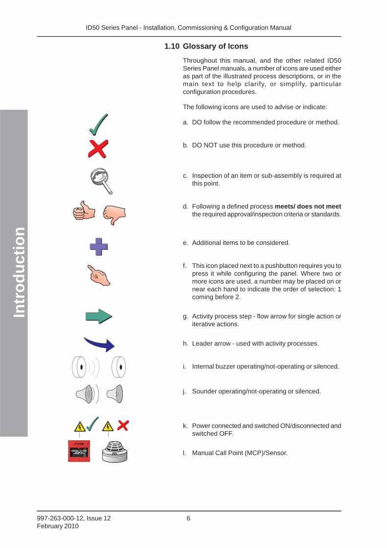
1.10 Glossary of Icons
Throughout this manual, and the other related ID50Series Panel manuals, a number of icons are used eitheras part of the illustrated process descriptions, or in themain text to help clarify, or simplify, particularconfiguration procedures.
The following icons are used to advise or indicate:
a. DO follow the recommended procedure or method.
b. DO NOT use this procedure or method.
c. Inspection of an item or sub-assembly is required atthis point.
d. Following a defined process meets/ does not meetthe required approval/inspection criteria or standards.
e. Additional items to be considered.
f. This icon placed next to a pushbutton requires you topress it while configuring the panel. Where two ormore icons are used, a number may be placed on ornear each hand to indicate the order of selection: 1coming before 2.
g. Activity process step - flow arrow for single action oriterative actions.
h. Leader arrow - used with activity processes.
i. Internal buzzer operating/not-operating or silenced.
j. Sounder operating/not-operating or silenced.
k. Power connected and switched ON/disconnected andswitched OFF.
l. Manual Call Point (MCP)/Sensor.
ID50 Series Panel - Installation, Commissioning & Configuration Manual
Inst
alla
tio
n G
uid
e
7 997-263-000-13, Issue 13October 2010
2 Installation Guide
2.1 How to Use this Section
This Installation Guide provides guidelines on how toinstall an ID50 Series Panel quickly and safely.
For each stage in the panel installation andcommissioning procedures a brief description is given ofits purpose, complete with detail drawings, flow diagramsand/or other graphics to make the instructions easy tofollow. Where required, procedures may be broken downinto one or more related diagrams, the number beingdependent upon the complexity of the defined task.
2.2 Pre-installation Check List
Before installing the ID50 Series Panel or fitting sensors,you must first ensure that the following criteria have beenmet. Failure to do this may not only result in damage tothe equipment, but may also cause problems whencommissioning the equipment or adversely affect itsperformance.
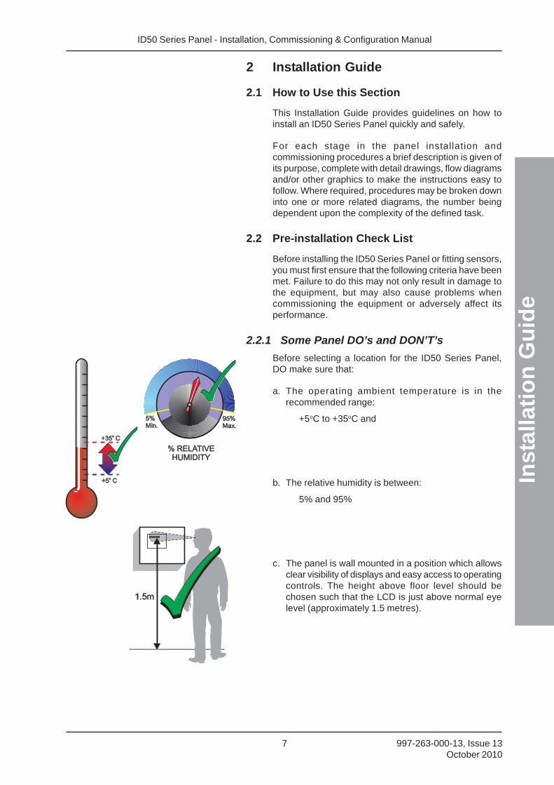
2.2.1 Some Panel DO’s and DON’T’s
Before selecting a location for the ID50 Series Panel,DO make sure that:
a. The operating ambient temperature is in therecommended range:
+5oC to +35oC and
b. The relative humidity is between:
5% and 95%
c. The panel is wall mounted in a position which allowsclear visibility of displays and easy access to operatingcontrols. The height above floor level should bechosen such that the LCD is just above normal eyelevel (approximately 1.5 metres).
ID50 Series Panel - Installation, Commissioning & Configuration Manual
Inst
alla
tio
n G
uid
e
8997-263-000-13, Issue 13October 2010
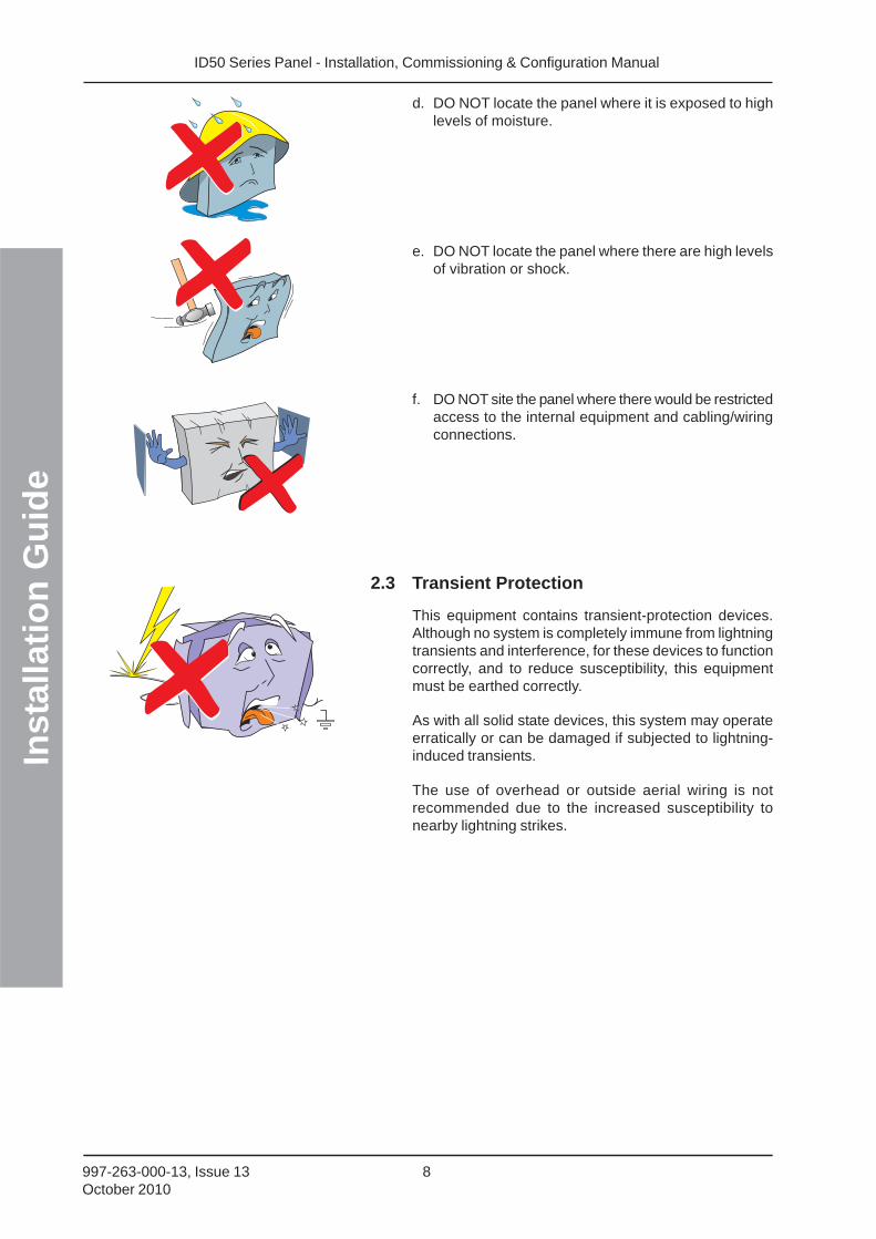
d. DO NOT locate the panel where it is exposed to highlevels of moisture.
e. DO NOT locate the panel where there are high levelsof vibration or shock.
f. DO NOT site the panel where there would be restrictedaccess to the internal equipment and cabling/wiringconnections.
2.3 Transient Protection
This equipment contains transient-protection devices.Although no system is completely immune from lightningtransients and interference, for these devices to functioncorrectly, and to reduce susceptibility, this equipmentmust be earthed correctly.
As with all solid state devices, this system may operateerratically or can be damaged if subjected to lightning-induced transients.
The use of overhead or outside aerial wiring is notrecommended due to the increased susceptibility tonearby lightning strikes.
ID50 Series Panel - Installation, Commissioning & Configuration Manual
Inst
alla
tio
n G
uid
e
9 997-263-000-13, Issue 13October 2010
2.4 Product Inspection
The ID50 Series Fire Control Panels are relatively simpleto install providing the recommended proceduresdescribed in this Installation Guide are followed.
Follow all installation instructions described in thismanual. These instructions must be understood andthe manufacturer’s recommendations followed toavoid damage to the control panel and associatedequipment.
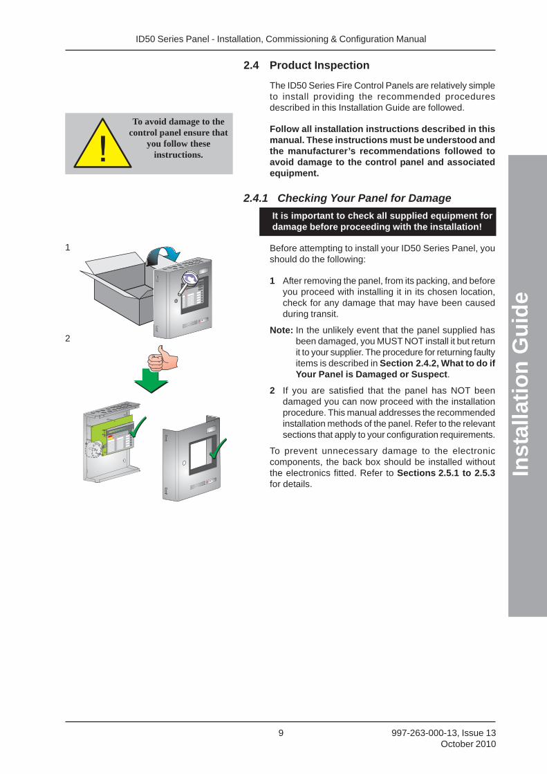
2.4.1 Checking Your Panel for Damage
It is important to check all supplied equipment fordamage before proceeding with the installation!
Before attempting to install your ID50 Series Panel, youshould do the following:
1 After removing the panel, from its packing, and beforeyou proceed with installing it in its chosen location,check for any damage that may have been causedduring transit.
Note: In the unlikely event that the panel supplied hasbeen damaged, you MUST NOT install it but returnit to your supplier. The procedure for returning faultyitems is described in Section 2.4.2, What to do ifYour Panel is Damaged or Suspect.
2 If you are satisfied that the panel has NOT beendamaged you can now proceed with the installationprocedure. This manual addresses the recommendedinstallation methods of the panel. Refer to the relevantsections that apply to your configuration requirements.
To prevent unnecessary damage to the electroniccomponents, the back box should be installed withoutthe electronics fitted. Refer to Sections 2.5.1 to 2.5.3for details.
To avoid damage to thecontrol panel ensure that
you follow theseinstructions.
1
2
ID50 Series Panel - Installation, Commissioning & Configuration Manual
Inst
alla
tio
n G
uid
e
10997-263-000-13, Issue 13October 2010
2.4.2What to do if Panel is Damaged or Suspect
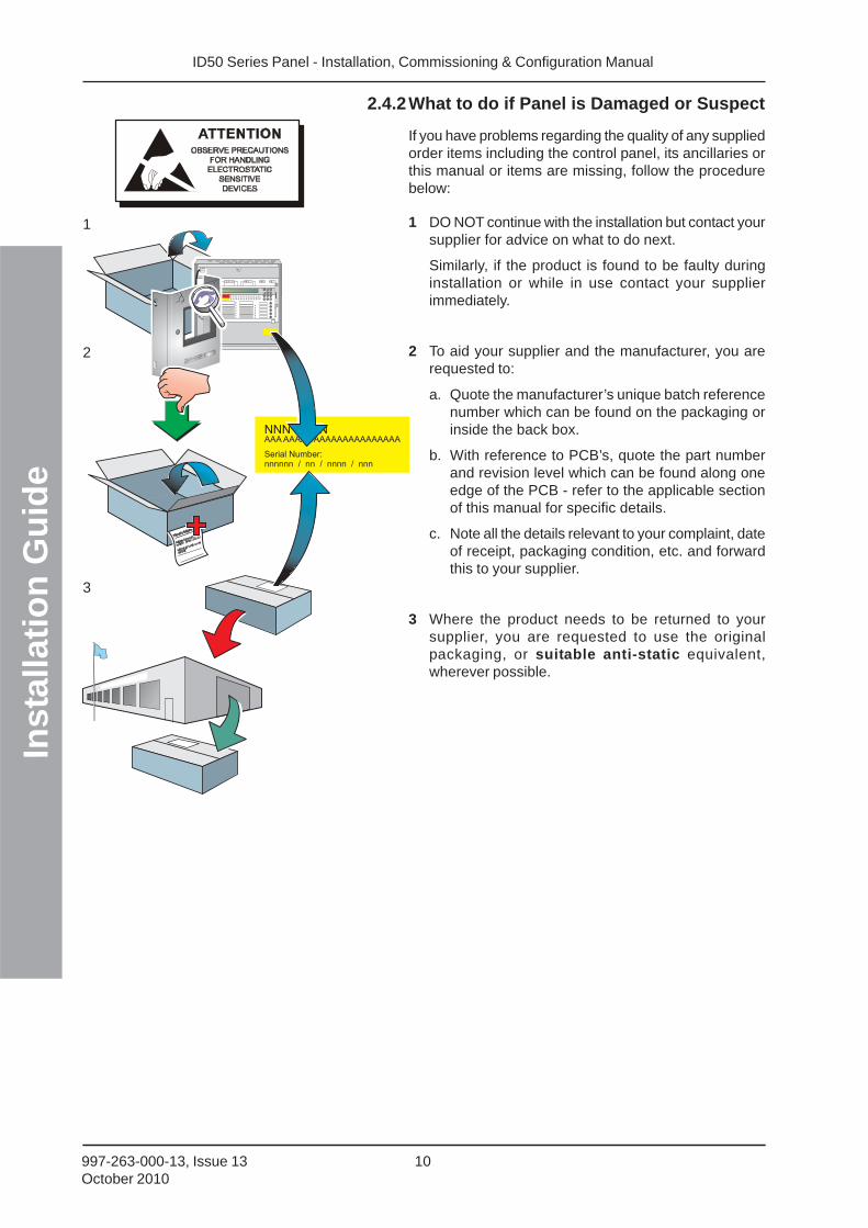
If you have problems regarding the quality of any suppliedorder items including the control panel, its ancillaries orthis manual or items are missing, follow the procedurebelow:
1 DO NOT continue with the installation but contact yoursupplier for advice on what to do next.
Similarly, if the product is found to be faulty duringinstallation or while in use contact your supplierimmediately.
2 To aid your supplier and the manufacturer, you arerequested to:
a. Quote the manufacturer’s unique batch referencenumber which can be found on the packaging orinside the back box.
b. With reference to PCB’s, quote the part numberand revision level which can be found along oneedge of the PCB - refer to the applicable sectionof this manual for specific details.
c. Note all the details relevant to your complaint, dateof receipt, packaging condition, etc. and forwardthis to your supplier.
3 Where the product needs to be returned to yoursupplier, you are requested to use the originalpackaging, or suitable anti-static equivalent,wherever possible.
1
2
3
ID50 Series Panel - Installation, Commissioning & Configuration Manual
Inst
alla
tio
n G
uid
e
11 997-263-000-13, Issue 13October 2010
2.5 Dismantling the Panel
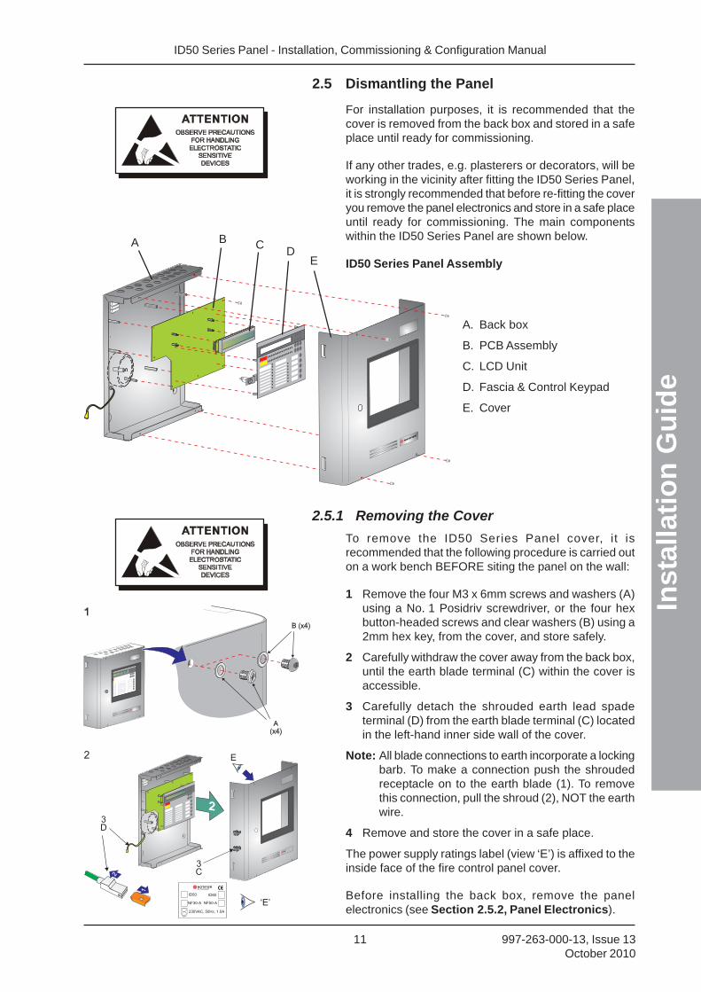
For installation purposes, it is recommended that thecover is removed from the back box and stored in a safeplace until ready for commissioning.
If any other trades, e.g. plasterers or decorators, will beworking in the vicinity after fitting the ID50 Series Panel,it is strongly recommended that before re-fitting the coveryou remove the panel electronics and store in a safe placeuntil ready for commissioning. The main componentswithin the ID50 Series Panel are shown below.
ID50 Series Panel Assembly
A. Back box
B. PCB Assembly
C. LCD Unit
D. Fascia & Control Keypad
E. Cover
2.5.1 Removing the Cover
To remove the ID50 Series Panel cover, it isrecommended that the following procedure is carried outon a work bench BEFORE siting the panel on the wall:
1 Remove the four M3 x 6mm screws and washers (A)using a No. 1 Posidriv screwdriver, or the four hexbutton-headed screws and clear washers (B) using a2mm hex key, from the cover, and store safely.
2 Carefully withdraw the cover away from the back box,until the earth blade terminal (C) within the cover isaccessible.
3 Carefully detach the shrouded earth lead spadeterminal (D) from the earth blade terminal (C) locatedin the left-hand inner side wall of the cover.
Note: All blade connections to earth incorporate a lockingbarb. To make a connection push the shroudedreceptacle on to the earth blade (1). To removethis connection, pull the shroud (2), NOT the earthwire.
4 Remove and store the cover in a safe place.
The power supply ratings label (view ‘E’) is affixed to theinside face of the fire control panel cover.
Before installing the back box, remove the panelelectronics (see Section 2.5.2, Panel Electronics).
A B CD
E
1
2
3D
2
3C
2
E
‘E’ID50
230VAC, 50Hz, 1.0A
ID60
NF30-A NF50-A
NOTIFIERby Honeywell
ID50 Series Panel - Installation, Commissioning & Configuration Manual
Inst
alla
tio
n G
uid
e
12997-263-000-13, Issue 13October 2010
2.5.2 Removing the Panel Electronics
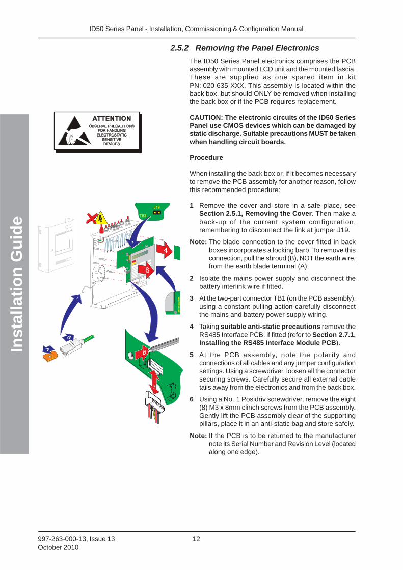
The ID50 Series Panel electronics comprises the PCBassembly with mounted LCD unit and the mounted fascia.These are supplied as one spared item in kitPN: 020-635-XXX. This assembly is located within theback box, but should ONLY be removed when installingthe back box or if the PCB requires replacement.
CAUTION: The electronic circuits of the ID50 SeriesPanel use CMOS devices which can be damaged bystatic discharge. Suitable precautions MUST be takenwhen handling circuit boards.
Procedure
When installing the back box or, if it becomes necessaryto remove the PCB assembly for another reason, followthis recommended procedure:
1 Remove the cover and store in a safe place, seeSection 2.5.1, Removing the Cover. Then make aback-up of the current system configuration,remembering to disconnect the link at jumper J19.
Note: The blade connection to the cover fitted in backboxes incorporates a locking barb. To remove thisconnection, pull the shroud (B), NOT the earth wire,from the earth blade terminal (A).
2 Isolate the mains power supply and disconnect thebattery interlink wire if fitted.
3 At the two-part connector TB1 (on the PCB assembly),using a constant pulling action carefully disconnectthe mains and battery power supply wiring.
4 Taking suitable anti-static precautions remove theRS485 Interface PCB, if fitted (refer to Section 2.7.1,Installing the RS485 Interface Module PCB).
5 At the PCB assembly, note the polarity andconnections of all cables and any jumper configurationsettings. Using a screwdriver, loosen all the connectorsecuring screws. Carefully secure all external cabletails away from the electronics and from the back box.
6 Using a No. 1 Posidriv screwdriver, remove the eight(8) M3 x 8mm clinch screws from the PCB assembly.Gently lift the PCB assembly clear of the supportingpillars, place it in an anti-static bag and store safely.
Note: If the PCB is to be returned to the manufacturernote its Serial Number and Revision Level (locatedalong one edge).
4
6
3
4i
6
A
1
B
394-1
91
issue
XX
X394-1
91
issu
eX
XX
TB3
J19
1
ID50 Series Panel - Installation, Commissioning & Configuration Manual
Inst
alla
tio
n G
uid
e
13 997-263-000-13, Issue 13October 2010
2.5.3 Back Box Fixing
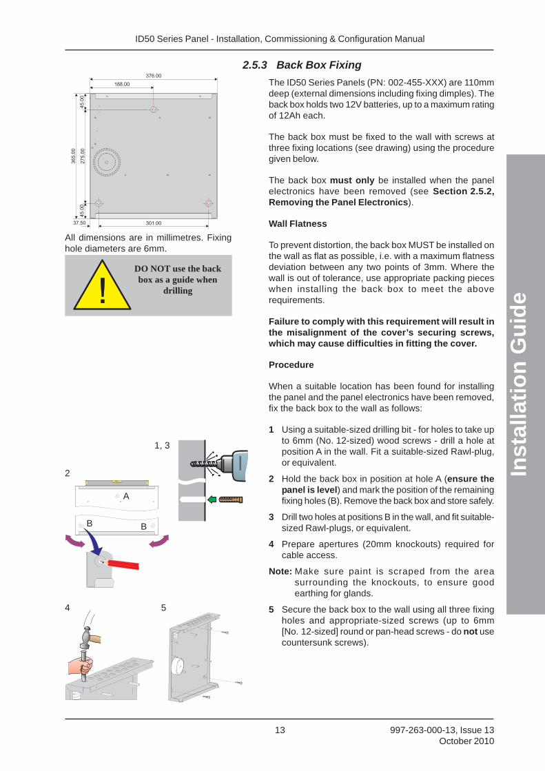
The ID50 Series Panels (PN: 002-455-XXX) are 110mmdeep (external dimensions including fixing dimples). Theback box holds two 12V batteries, up to a maximum ratingof 12Ah each.
The back box must be fixed to the wall with screws atthree fixing locations (see drawing) using the proceduregiven below.
The back box must only be installed when the panelelectronics have been removed (see Section 2.5.2,Removing the Panel Electronics).
Wall Flatness
To prevent distortion, the back box MUST be installed onthe wall as flat as possible, i.e. with a maximum flatnessdeviation between any two points of 3mm. Where thewall is out of tolerance, use appropriate packing pieceswhen installing the back box to meet the aboverequirements.
Failure to comply with this requirement will result inthe misalignment of the cover’s securing screws,which may cause difficulties in fitting the cover.
Procedure
When a suitable location has been found for installingthe panel and the panel electronics have been removed,fix the back box to the wall as follows:
1 Using a suitable-sized drilling bit - for holes to take upto 6mm (No. 12-sized) wood screws - drill a hole atposition A in the wall. Fit a suitable-sized Rawl-plug,or equivalent.
2 Hold the back box in position at hole A (ensure thepanel is level) and mark the position of the remainingfixing holes (B). Remove the back box and store safely.
3 Drill two holes at positions B in the wall, and fit suitable-sized Rawl-plugs, or equivalent.
4 Prepare apertures (20mm knockouts) required forcable access.
Note: Make sure paint is scraped from the areasurrounding the knockouts, to ensure goodearthing for glands.
5 Secure the back box to the wall using all three fixingholes and appropriate-sized screws (up to 6mm[No. 12-sized] round or pan-head screws - do not usecountersunk screws).
DO NOT use the backbox as a guide when
drilling
All dimensions are in millimetres. Fixinghole diameters are 6mm.
37.50 301.00
376.004
5.0
0
36
5.0
0
27
5.0
0188.00
45
.00
4
2
1, 3
5
A
B B
ID50 Series Panel - Installation, Commissioning & Configuration Manual
Inst
alla
tio
n G
uid
e
14997-263-000-13, Issue 13October 2010
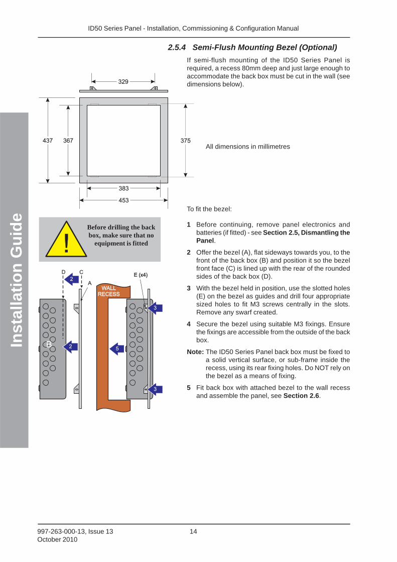
2.5.4 Semi-Flush Mounting Bezel (Optional)
If semi-flush mounting of the ID50 Series Panel isrequired, a recess 80mm deep and just large enough toaccommodate the back box must be cut in the wall (seedimensions below).
All dimensions in millimetres
To fit the bezel:
1 Before continuing, remove panel electronics andbatteries (if fitted) - see Section 2.5, Dismantling thePanel.
2 Offer the bezel (A), flat sideways towards you, to thefront of the back box (B) and position it so the bezelfront face (C) is lined up with the rear of the roundedsides of the back box (D).
3 With the bezel held in position, use the slotted holes(E) on the bezel as guides and drill four appropriatesized holes to fit M3 screws centrally in the slots.Remove any swarf created.
4 Secure the bezel using suitable M3 fixings. Ensurethe fixings are accessible from the outside of the backbox.
Note: The ID50 Series Panel back box must be fixed toa solid vertical surface, or sub-frame inside therecess, using its rear fixing holes. Do NOT rely onthe bezel as a means of fixing.
5 Fit back box with attached bezel to the wall recessand assemble the panel, see Section 2.6.
Before drilling the backbox, make sure that no
equipment is fitted
367437
383
453
329
375
D
B
C
2 5
2
WALLRECESS
WALLRECESS
E (x4)E (x4)
3
3
A
ID50 Series Panel - Installation, Commissioning & Configuration Manual
Inst
alla
tio
n G
uid
e
15 997-263-000-13, Issue 13October 2010
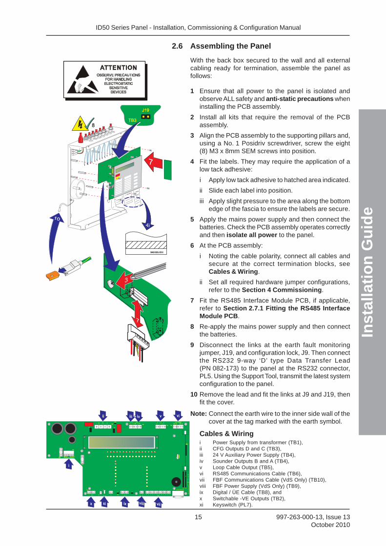
2.6 Assembling the Panel
With the back box secured to the wall and all externalcabling ready for termination, assemble the panel asfollows:
1 Ensure that all power to the panel is isolated andobserve ALL safety and anti-static precautions wheninstalling the PCB assembly.
2 Install all kits that require the removal of the PCBassembly.
3 Align the PCB assembly to the supporting pillars and,using a No. 1 Posidriv screwdriver, screw the eight(8) M3 x 8mm SEM screws into position.
4 Fit the labels. They may require the application of alow tack adhesive:
i Apply low tack adhesive to hatched area indicated.
ii Slide each label into position.
iii Apply slight pressure to the area along the bottomedge of the fascia to ensure the labels are secure.
5 Apply the mains power supply and then connect thebatteries. Check the PCB assembly operates correctlyand then isolate all power to the panel.
6 At the PCB assembly:
i Noting the cable polarity, connect all cables andsecure at the correct termination blocks, seeCables & Wiring.
ii Set all required hardware jumper configurations,refer to the Section 4 Commissioning.
7 Fit the RS485 Interface Module PCB, if applicable,refer to Section 2.7.1 Fitting the RS485 InterfaceModule PCB.
8 Re-apply the mains power supply and then connectthe batteries.
9 Disconnect the links at the earth fault monitoringjumper, J19, and configuration lock, J9. Then connectthe RS232 9-way ‘D’ type Data Transfer Lead(PN 082-173) to the panel at the RS232 connector,PL5. Using the Support Tool, transmit the latest systemconfiguration to the panel.
10 Remove the lead and fit the links at J9 and J19, thenfit the cover.
Note: Connect the earth wire to the inner side wall of thecover at the tag marked with the earth symbol.
Cables & Wiringi Power Supply from transformer (TB1),ii CFG Outputs D and C (TB3),iii 24 V Auxiliary Power Supply (TB4),iv Sounder Outputs B and A (TB4),v Loop Cable Output (TB5),vi RS485 Communications Cable (TB6),vii FBF Communications Cable (VdS Only) (TB10),viii FBF Power Supply (VdS Only) (TB9),ix Digital / ÜE Cable (TB8), andx Switchable -VE Outputs (TB2),xi Keyswitch (PL7).
ID50 Series Panel - Installation, Commissioning & Configuration Manual
Inst
alla
tio
n G
uid
e
16997-263-000-13, Issue 13October 2010
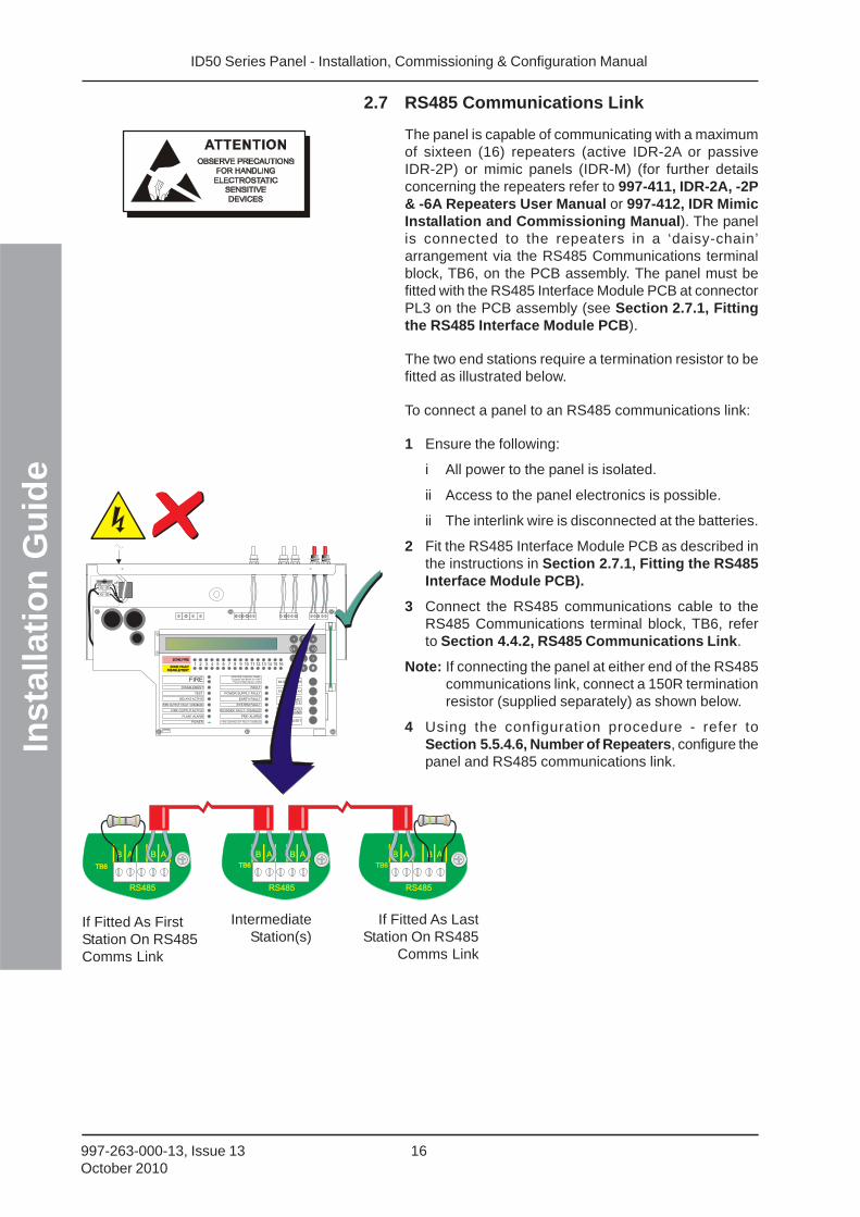
2.7 RS485 Communications Link
The panel is capable of communicating with a maximumof sixteen (16) repeaters (active IDR-2A or passiveIDR-2P) or mimic panels (IDR-M) (for further detailsconcerning the repeaters refer to 997-411, IDR-2A, -2P& -6A Repeaters User Manual or 997-412, IDR MimicInstallation and Commissioning Manual). The panelis connected to the repeaters in a ‘daisy-chain’arrangement via the RS485 Communications terminalblock, TB6, on the PCB assembly. The panel must befitted with the RS485 Interface Module PCB at connectorPL3 on the PCB assembly (see Section 2.7.1, Fittingthe RS485 Interface Module PCB).
The two end stations require a termination resistor to befitted as illustrated below.
To connect a panel to an RS485 communications link:
1 Ensure the following:
i All power to the panel is isolated.
ii Access to the panel electronics is possible.
ii The interlink wire is disconnected at the batteries.
2 Fit the RS485 Interface Module PCB as described inthe instructions in Section 2.7.1, Fitting the RS485Interface Module PCB).
3 Connect the RS485 communications cable to theRS485 Communications terminal block, TB6, referto Section 4.4.2, RS485 Communications Link.
Note: If connecting the panel at either end of the RS485communications link, connect a 150R terminationresistor (supplied separately) as shown below.
4 Using the configuration procedure - refer toSection 5.5.4.6, Number of Repeaters, configure thepanel and RS485 communications link.
If Fitted As FirstStation On RS485Comms Link
IntermediateStation(s)
If Fitted As LastStation On RS485
Comms Link
RS485
B A B A
RS485
B A B A
RS485
B A B A
TB6TB6TB6TB6TB6
NL
FIREDISABLEMENT
ID50 FIRE CONTROL PANELComplies with EN54-2/4 1997
Period of Manufacture 1999
FAULT
RESET
EXTEND DELAYTEST POWER SUPPLY FAULT
EARTH FAULT
POWER
PLANT ALARM
FIRE OUTPUT ACTIVE
DELAYS ACTIVE
FIRE OUTPUT: FAULT / DISABLED
FIRE CONTROL O/P: FAULT / DISABLED
PRE- ALARM
SYSTEM FAULT
SOUNDER: FAULT / DISABLED
MUTE BUZZER
SILENCE/RESOUND
END DELAY/EVACUATE
1 2 3 4 5 6 7 8 9 10 11 12 13 14 15 16ZONE FIREZONE FIRE
ZONE FAULTDISABLE/TEST
ZONE FAULTDISABLE/TEST
00..9
31
�
2
4 6
7
5�
98
ID50 Series Panel - Installation, Commissioning & Configuration Manual
Inst
alla
tio
n G
uid
e
17 997-263-000-13, Issue 13October 2010
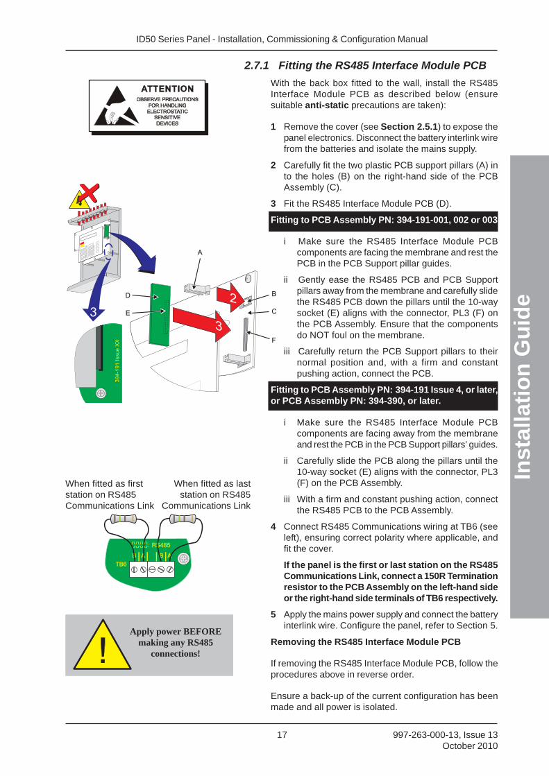
2.7.1 Fitting the RS485 Interface Module PCB
With the back box fitted to the wall, install the RS485Interface Module PCB as described below (ensuresuitable anti-static precautions are taken):
1 Remove the cover (see Section 2.5.1) to expose thepanel electronics. Disconnect the battery interlink wirefrom the batteries and isolate the mains supply.
2 Carefully fit the two plastic PCB support pillars (A) into the holes (B) on the right-hand side of the PCBAssembly (C).
3 Fit the RS485 Interface Module PCB (D).
Fitting to PCB Assembly PN: 394-191-001, 002 or 003
i Make sure the RS485 Interface Module PCBcomponents are facing the membrane and rest thePCB in the PCB Support pillar guides.
ii Gently ease the RS485 PCB and PCB Supportpillars away from the membrane and carefully slidethe RS485 PCB down the pillars until the 10-waysocket (E) aligns with the connector, PL3 (F) onthe PCB Assembly. Ensure that the componentsdo NOT foul on the membrane.
iii Carefully return the PCB Support pillars to theirnormal position and, with a firm and constantpushing action, connect the PCB.
Fitting to PCB Assembly PN: 394-191 Issue 4, or later,or PCB Assembly PN: 394-390, or later.
i Make sure the RS485 Interface Module PCBcomponents are facing away from the membraneand rest the PCB in the PCB Support pillars’ guides.
ii Carefully slide the PCB along the pillars until the10-way socket (E) aligns with the connector, PL3(F) on the PCB Assembly.
iii With a firm and constant pushing action, connectthe RS485 PCB to the PCB Assembly.
4 Connect RS485 Communications wiring at TB6 (seeleft), ensuring correct polarity where applicable, andfit the cover.
If the panel is the first or last station on the RS485Communications Link, connect a 150R Terminationresistor to the PCB Assembly on the left-hand sideor the right-hand side terminals of TB6 respectively.
5 Apply the mains power supply and connect the batteryinterlink wire. Configure the panel, refer to Section 5.
Removing the RS485 Interface Module PCB
If removing the RS485 Interface Module PCB, follow theprocedures above in reverse order.
Ensure a back-up of the current configuration has beenmade and all power is isolated.
When fitted as firststation on RS485Communications Link
When fitted as laststation on RS485
Communications Link
A
D
E
B
F
C
2
33
394-1
91
Issue
XX
Apply power BEFOREmaking any RS485
connections!
ID50 Series Panel - Installation, Commissioning & Configuration Manual
Inst
alla
tio
n G
uid
e
18997-263-000-13, Issue 13October 2010
NL
TB3
J19
RS232
FIREDISABLEMENT
ID50 FIRE CONTROL PANELComplies with EN54-2/4 1997
Period of Manufacture 1999
FAULT
RESET
EXTEND DELAYTEST POWER SUPPLY FAULT
EARTH FAULT
POWER
PLANT ALARM
FIRE OUTPUT ACTIVE
DELAYS ACTIVE
FIRE OUTPUT: FAULT / DISABLED
FIRE CONTROL O/P: FAULT / DISABLED
PRE- ALARM
SYSTEM FAULT
SOUNDER: FAULT / DISABLED
MUTE BUZZER
SILENCE/RESOUND
END DELAY/EVACUATE
1 2 3 4 5 6 7 8 9 10 11 12 13 14 15 16ZONE FIREZONE FIRE
ZONE FAULTDISABLE/TEST
ZONE FAULTDISABLE/TEST
00..9
31
�
2
4 6
7
5�
98
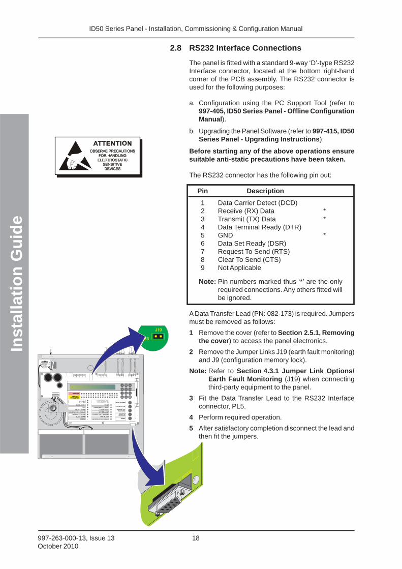
2.8 RS232 Interface Connections
The panel is fitted with a standard 9-way ‘D’-type RS232Interface connector, located at the bottom right-handcorner of the PCB assembly. The RS232 connector isused for the following purposes:
a. Configuration using the PC Support Tool (refer to997-405, ID50 Series Panel - Offline ConfigurationManual).
b. Upgrading the Panel Software (refer to 997-415, ID50Series Panel - Upgrading Instructions).
Before starting any of the above operations ensuresuitable anti-static precautions have been taken.
The RS232 connector has the following pin out:
Pin Description
1 Data Carrier Detect (DCD)2 Receive (RX) Data *3 Transmit (TX) Data *4 Data Terminal Ready (DTR)5 GND *6 Data Set Ready (DSR)7 Request To Send (RTS)8 Clear To Send (CTS)9 Not Applicable
Note: Pin numbers marked thus ‘*’ are the onlyrequired connections. Any others fitted willbe ignored.
A Data Transfer Lead (PN: 082-173) is required. Jumpersmust be removed as follows:
1 Remove the cover (refer to Section 2.5.1, Removingthe cover) to access the panel electronics.
2 Remove the Jumper Links J19 (earth fault monitoring)and J9 (configuration memory lock).
Note: Refer to Section 4.3.1 Jumper Link Options/Earth Fault Monitoring (J19) when connectingthird-party equipment to the panel.
3 Fit the Data Transfer Lead to the RS232 Interfaceconnector, PL5.
4 Perform required operation.
5 After satisfactory completion disconnect the lead andthen fit the jumpers.
ID50 Series Panel - Installation, Commissioning & Configuration Manual
Inst
alla
tio
n G
uid
e -
Cab
ling
19 997-263-000-13, Issue 13October 2010
3 Cabling
3.1 Cabling Instructions
All wiring should comply with current IEE wiringregulations (BS7671) or the applicable local wiringregulations. Note also the requirements of EN54-14 forcabling and interconnection of a fire detection and alarmsystem.
For information on wiring inputs and outputs refer to theappropriate module cable and wiring instructions toidentify terminals. Refer also to Commissioning,Section 4.4 External Wiring Checks for details.
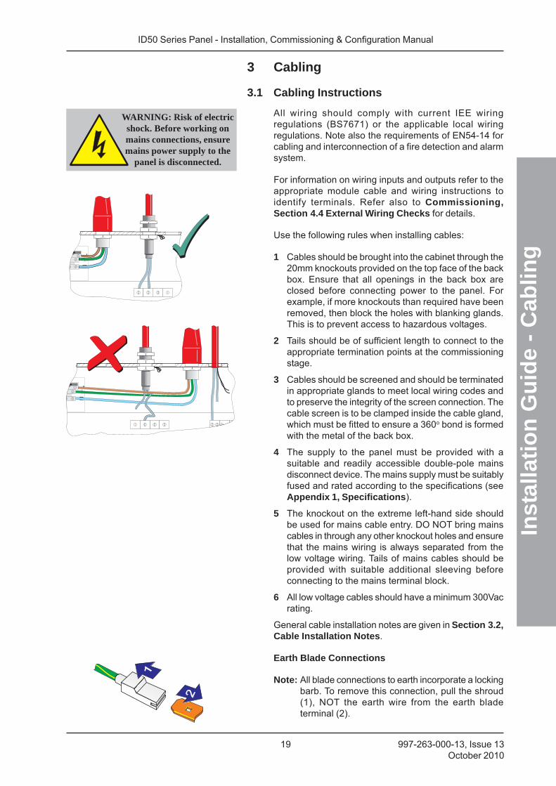
Use the following rules when installing cables:
1 Cables should be brought into the cabinet through the20mm knockouts provided on the top face of the backbox. Ensure that all openings in the back box areclosed before connecting power to the panel. Forexample, if more knockouts than required have beenremoved, then block the holes with blanking glands.This is to prevent access to hazardous voltages.
2 Tails should be of sufficient length to connect to theappropriate termination points at the commissioningstage.
3 Cables should be screened and should be terminatedin appropriate glands to meet local wiring codes andto preserve the integrity of the screen connection. Thecable screen is to be clamped inside the cable gland,which must be fitted to ensure a 360o bond is formedwith the metal of the back box.
4 The supply to the panel must be provided with asuitable and readily accessible double-pole mainsdisconnect device. The mains supply must be suitablyfused and rated according to the specifications (seeAppendix 1, Specifications).
5 The knockout on the extreme left-hand side shouldbe used for mains cable entry. DO NOT bring mainscables in through any other knockout holes and ensurethat the mains wiring is always separated from thelow voltage wiring. Tails of mains cables should beprovided with suitable additional sleeving beforeconnecting to the mains terminal block.
6 All low voltage cables should have a minimum 300Vacrating.
General cable installation notes are given in Section 3.2,Cable Installation Notes.
Earth Blade Connections
Note: All blade connections to earth incorporate a lockingbarb. To remove this connection, pull the shroud(1), NOT the earth wire from the earth bladeterminal (2).
WARNING: Risk of electricshock. Before working onmains connections, ensuremains power supply to the
panel is disconnected.
ID50 Series Panel - Installation, Commissioning & Configuration Manual
Inst
alla
tio
n G
uid
e -
Cab
ling
20997-263-000-13, Issue 13October 2010
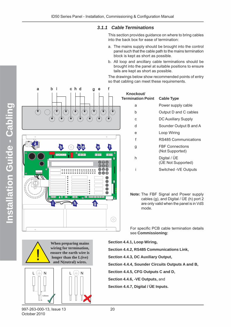
3.1.1 Cable Terminations
This section provides guidance on where to bring cablesinto the back box for ease of termination:
a. The mains supply should be brought into the controlpanel such that the cable path to the mains terminationblock is kept as short as possible.
b. All loop and ancillary cable terminations should bebrought into the panel at suitable positions to ensuretails are kept as short as possible.
The drawings below show recommended points of entryso that cabling can meet these requirements.
Knockout/Termination Point Cable Type
a Power supply cable
b Output D and C cables
c DC Auxiliary Supply
d Sounder Output B and A
e Loop Wiring
f RS485 Communications
g FBF Connections(Not Supported)
h Digital / ÜE(ÜE Not Supported)
i Switched -VE Outputs
Note: The FBF Signal and Power supplycables (g), and Digital / ÜE (h) port 2are only valid when the panel is in VdSmode.
For specific PCB cable termination detailssee Commissioning:
Section 4.4.1, Loop Wiring,
Section 4.4.2, RS485 Communications Link,
Section 4.4.3, DC Auxiliary Output,
Section 4.4.4, Sounder Circuits Outputs A and B,
Section 4.4.5, CFG Outputs C and D,
Section 4.4.6, -VE Outputs, and
Section 4.4.7, Digital / ÜE Inputs.
When preparing mainswiring for termination,ensure the earth wire islonger than the L(ive)and N(eutral) wires.
ID50 Series Panel - Installation, Commissioning & Configuration Manual
Inst
alla
tio
n G
uid
e -
Cab
ling
21 997-263-000-13, Issue 13October 2010
3.2 Cabling Installation Notes
3.2.1 Introduction
The following notes are intended to assist installers ofanalogue addressable control systems. They have beenproduced from information derived from the supplier’stechnical resource and from information fed backconcerning existing systems.
3.2.2 Quality of Cable and of Cable Installation
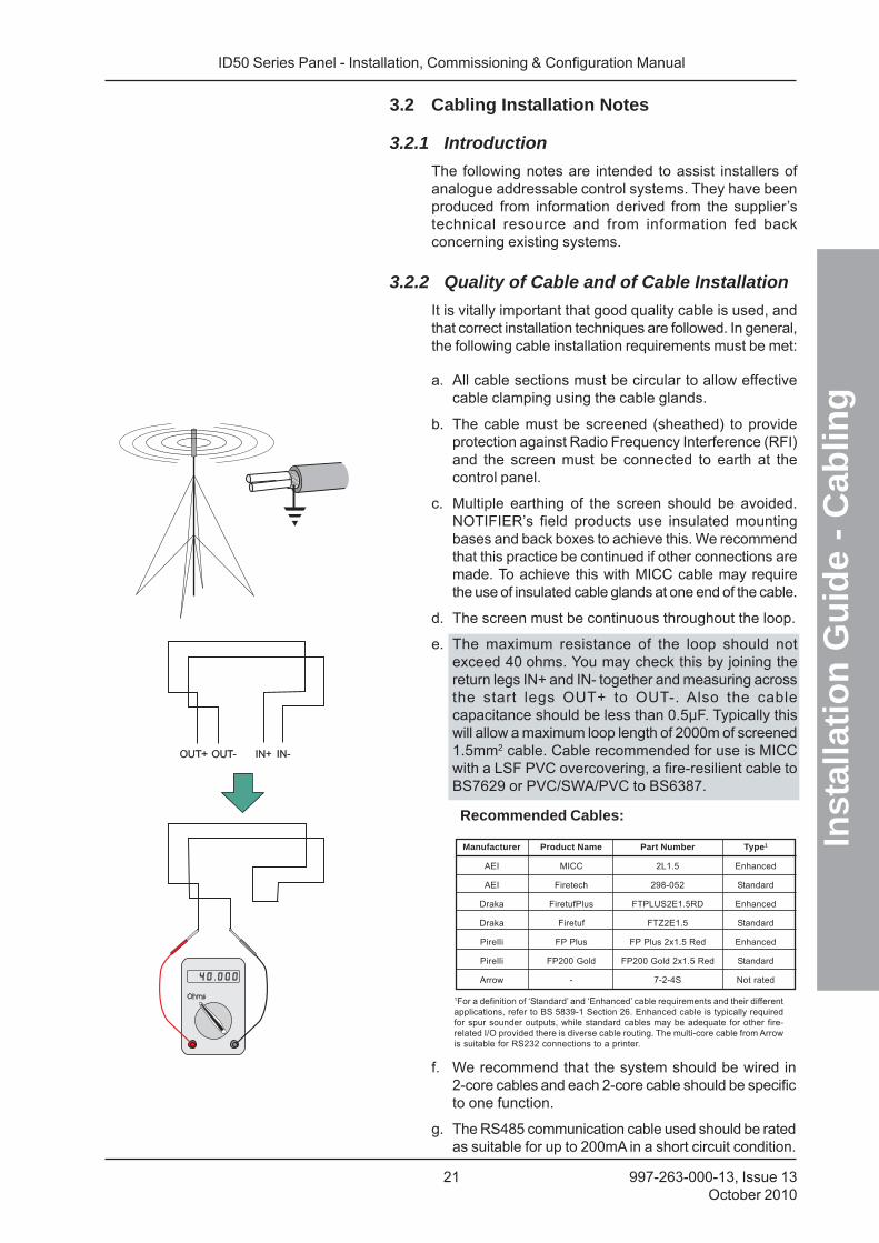
It is vitally important that good quality cable is used, andthat correct installation techniques are followed. In general,the following cable installation requirements must be met:
a. All cable sections must be circular to allow effectivecable clamping using the cable glands.
b. The cable must be screened (sheathed) to provideprotection against Radio Frequency Interference (RFI)and the screen must be connected to earth at thecontrol panel.
c. Multiple earthing of the screen should be avoided.NOTIFIER’s field products use insulated mountingbases and back boxes to achieve this. We recommendthat this practice be continued if other connections aremade. To achieve this with MICC cable may requirethe use of insulated cable glands at one end of the cable.
d. The screen must be continuous throughout the loop.
e. The maximum resistance of the loop should notexceed 40 ohms. You may check this by joining thereturn legs IN+ and IN- together and measuring acrossthe start legs OUT+ to OUT-. Also the cablecapacitance should be less than 0.5μF. Typically thiswill allow a maximum loop length of 2000m of screened1.5mm2 cable. Cable recommended for use is MICCwith a LSF PVC overcovering, a fire-resilient cable toBS7629 or PVC/SWA/PVC to BS6387.
Recommended Cables:
Manufacturer Product Name Part Number Type1
AEI MICC 2L1.5 Enhanced
AEI Firetech 298-052 Standard
Draka FiretufPlus FTPLUS2E1.5RD Enhanced
Draka Firetuf FTZ2E1.5 Standard
Pirelli FP Plus FP Plus 2x1.5 Red Enhanced
Pirelli FP200 Gold FP200 Gold 2x1.5 Red Standard
Arrow - 7-2-4S Not rated
1For a definition of ‘Standard’ and ‘Enhanced’ cable requirements and their differentapplications, refer to BS 5839-1 Section 26. Enhanced cable is typically requiredfor spur sounder outputs, while standard cables may be adequate for other fire-related I/O provided there is diverse cable routing. The multi-core cable from Arrowis suitable for RS232 connections to a printer.
f. We recommend that the system should be wired in2-core cables and each 2-core cable should be specificto one function.
g. The RS485 communication cable used should be ratedas suitable for up to 200mA in a short circuit condition.
ID50 Series Panel - Installation, Commissioning & Configuration Manual
Inst
alla
tio
n G
uid
e -
Cab
ling
22997-263-000-13, Issue 13October 2010
3.3 EMC Considerations
Following the above instructions and by using suitablecables EMC problems will be avoided. In particularlydifficult EMC environments, or where non-preferredcabling is used, it is possible to fit additional ferritesuppressors (sleeves) to cables entering the controlpanel.
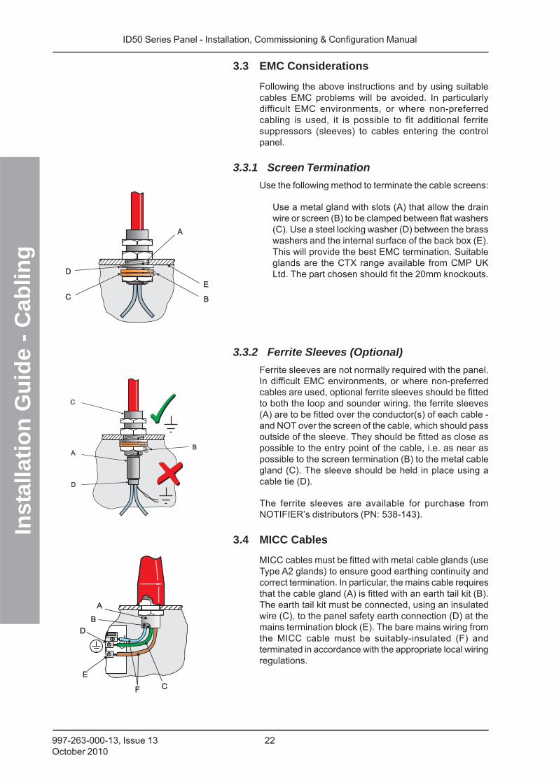
3.3.1 Screen Termination
Use the following method to terminate the cable screens:
Use a metal gland with slots (A) that allow the drainwire or screen (B) to be clamped between flat washers(C). Use a steel locking washer (D) between the brasswashers and the internal surface of the back box (E).This will provide the best EMC termination. Suitableglands are the CTX range available from CMP UKLtd. The part chosen should fit the 20mm knockouts.
3.3.2 Ferrite Sleeves (Optional)
Ferrite sleeves are not normally required with the panel.In difficult EMC environments, or where non-preferredcables are used, optional ferrite sleeves should be fittedto both the loop and sounder wiring. the ferrite sleeves(A) are to be fitted over the conductor(s) of each cable -and NOT over the screen of the cable, which should passoutside of the sleeve. They should be fitted as close aspossible to the entry point of the cable, i.e. as near aspossible to the screen termination (B) to the metal cablegland (C). The sleeve should be held in place using acable tie (D).
The ferrite sleeves are available for purchase fromNOTIFIER’s distributors (PN: 538-143).
3.4 MICC Cables
MICC cables must be fitted with metal cable glands (useType A2 glands) to ensure good earthing continuity andcorrect termination. In particular, the mains cable requiresthat the cable gland (A) is fitted with an earth tail kit (B).The earth tail kit must be connected, using an insulatedwire (C), to the panel safety earth connection (D) at themains termination block (E). The bare mains wiring fromthe MICC cable must be suitably-insulated (F) andterminated in accordance with the appropriate local wiringregulations.
ID50 Series Panel - Installation, Commissioning & Configuration Manual
Co
mm
issi
on
ing
23 997-263-000-13, Issue 13October 2010
4 Commissioning
4.1 Introduction
This section describes how to bring the ID50 Series Panelinto an operational state (commissioning) ready forconfiguration. To commission this series of panels followthe steps detailed below. Information on how to configurethe panel is given in Section 5, Configuration.
1 Check that the panel is installed and assembledcorrectly, refer to Section 4.2, Preliminary Checks.
2 Check internal panel configuration, Section 4.3,Internal Checks.
3 Check and connect the external wiring, refer toSection 4.4, External Wiring Checks.
4 Configure the panel for the particular systemrequirements, refer to Section 5, Configuration.
5 Check that the system is working correctly.
4.2 Preliminary Checks
Before connecting the mains power to the panel, checkthat:
a. All PCBs are correctly fitted.
b. All internal wiring is correctly connected.
c. The loop wiring and external sounder circuits haveNOT, at this stage, been connected to the PCB.
d. Check that there are no more than 40 CLIP deviceaddresses on a mixed-protocol loop1.
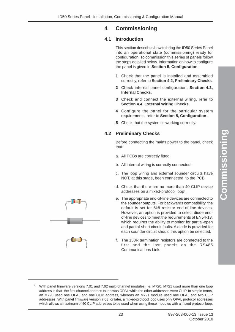
e. The appropriate end-of-line devices are connected tothe sounder outputs. For backwards compatibility, thedefault is set for 6k8 resistor end-of-line devices.However, an option is provided to select diode end-of-line devices to meet the requirements of EN54-13,which requires the ability to monitor for partial-openand partial-short circuit faults. A diode is provided foreach sounder circuit should this option be selected.
f. The 150R termination resistors are connected to thefirst and the last panels on the RS485Communications Link.
1 With panel firmware versions 7.01 and 7.02 multi-channel modules, i.e. M720, M721 used more than one loopaddress in that the first channel address taken was OPAL while the other addresses were CLIP. In simple terms,an M720 used one OPAL and one CLIP address, whereas an M721 module used one OPAL and two CLIPaddresses. With panel firmware version 7.03, or later, a mixed-protocol loop uses only OPAL protocol addresseswhich allows a maximum of 40 CLIP addresses to be used when using these modules with a mixed protocol loop.
ID50 Series Panel - Installation, Commissioning & Configuration Manual
Co
mm
issi
on
ing
24997-263-000-13, Issue 13October 2010
4.3 Internal ChecksWhen all PCBs have been installed and all cabling hasbeen successfully checked, the following jumper linksallow the implementation of panel software orconfiguration updates, as described below.
4.3.1 Jumper Link Options
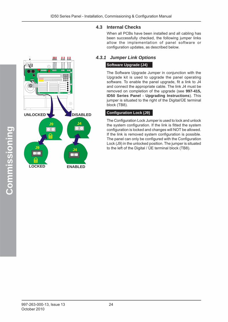
Software Upgrade (J4)
The Software Upgrade Jumper in conjunction with theUpgrade kit is used to upgrade the panel operatingsoftware. To enable the panel upgrade, fit a link to J4and connect the appropriate cable. The link J4 must beremoved on completion of the upgrade (see 997-415,ID50 Series Panel - Upgrading Instructions). Thisjumper is situated to the right of the Digital/ÜE terminalblock (TB8).
Configuration Lock (J9)
The Configuration Lock Jumper is used to lock and unlockthe system configuration. If the link is fitted the systemconfiguration is locked and changes will NOT be allowed.If the link is removed system configuration is possible.The panel can only be configured with the ConfigurationLock (J9) in the unlocked position. The jumper is situatedto the left of the Digital / ÜE terminal block (TB8).
J9
J9
J4
J4
ENABLEDLOCKED
DISABLEDUNLOCKED
ID50 Series Panel - Installation, Commissioning & Configuration Manual
Co
mm
issi
on
ing
25 997-263-000-13, Issue 13October 2010
EN54-2 : 8.2.4c.Earth Fault Monitoring
is required.
ENABLEDDISABLED
J19 J19
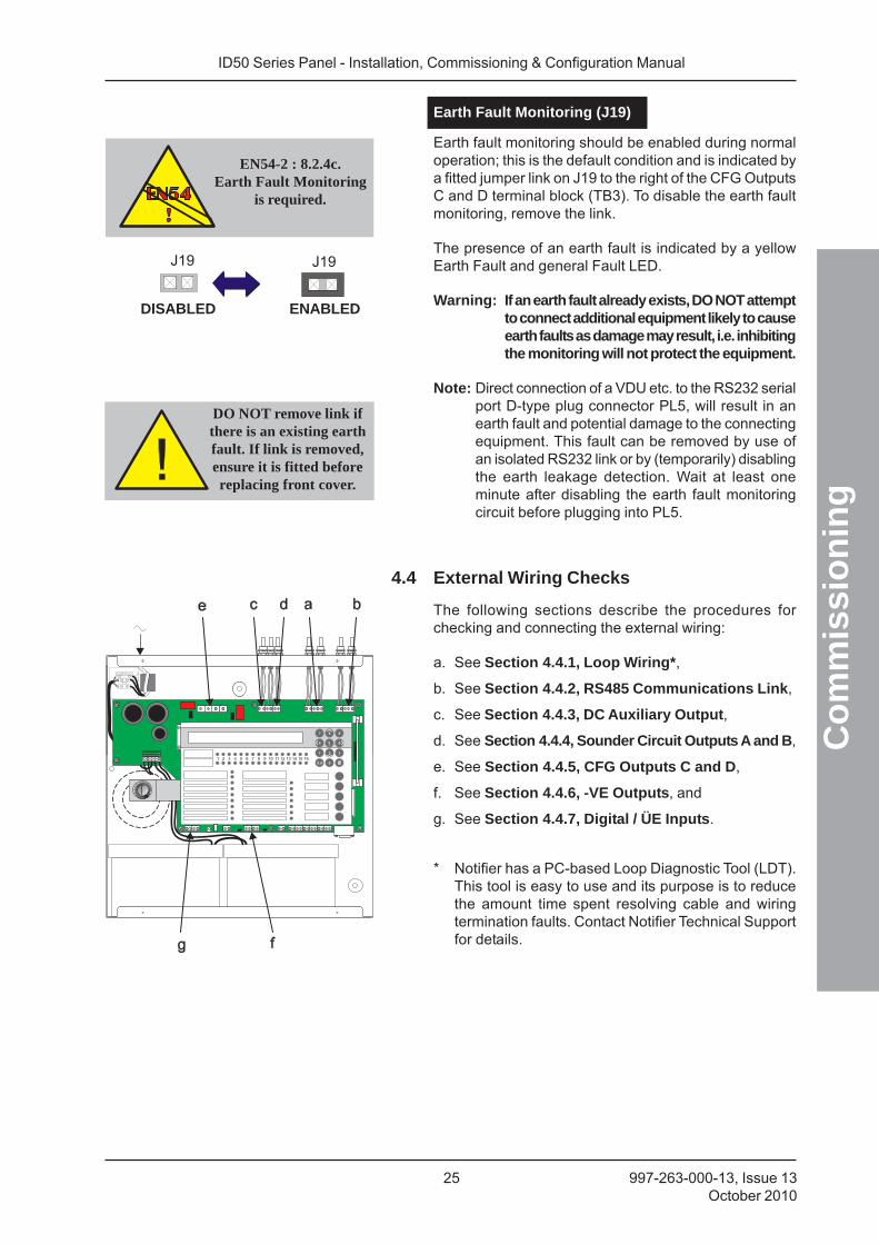
Earth Fault Monitoring (J19)
Earth fault monitoring should be enabled during normaloperation; this is the default condition and is indicated bya fitted jumper link on J19 to the right of the CFG OutputsC and D terminal block (TB3). To disable the earth faultmonitoring, remove the link.
The presence of an earth fault is indicated by a yellowEarth Fault and general Fault LED.
Warning: If an earth fault already exists, DO NOT attemptto connect additional equipment likely to causeearth faults as damage may result, i.e. inhibitingthe monitoring will not protect the equipment.
Note: Direct connection of a VDU etc. to the RS232 serialport D-type plug connector PL5, will result in anearth fault and potential damage to the connectingequipment. This fault can be removed by use ofan isolated RS232 link or by (temporarily) disablingthe earth leakage detection. Wait at least oneminute after disabling the earth fault monitoringcircuit before plugging into PL5.
4.4 External Wiring Checks
The following sections describe the procedures forchecking and connecting the external wiring:
a. See Section 4.4.1, Loop Wiring*,
b. See Section 4.4.2, RS485 Communications Link,
c. See Section 4.4.3, DC Auxiliary Output,
d. See Section 4.4.4, Sounder Circuit Outputs A and B,
e. See Section 4.4.5, CFG Outputs C and D,
f. See Section 4.4.6, -VE Outputs, and
g. See Section 4.4.7, Digital / ÜE Inputs.
DO NOT remove link ifthere is an existing earthfault. If link is removed,ensure it is fitted beforereplacing front cover.
* Notifier has a PC-based Loop Diagnostic Tool (LDT).This tool is easy to use and its purpose is to reducethe amount time spent resolving cable and wiringtermination faults. Contact Notifier Technical Supportfor details.
ID50 Series Panel - Installation, Commissioning & Configuration Manual
Co
mm
issi
on
ing
26997-263-000-13, Issue 13October 2010
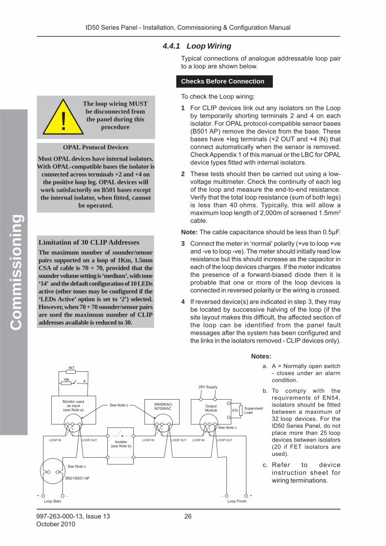
4.4.1 Loop Wiring
Typical connections of analogue addressable loop pairto a loop are shown below.
Checks Before Connection
To check the Loop wiring:
1 For CLIP devices link out any isolators on the Loopby temporarily shorting terminals 2 and 4 on eachisolator. For OPAL protocol-compatible sensor bases(B501 AP) remove the device from the base. Thesebases have +leg terminals (+2 OUT and +4 IN) thatconnect automatically when the sensor is removed.Check Appendix 1 of this manual or the LBC for OPALdevice types fitted with internal isolators.
2 These tests should then be carried out using a low-voltage multimeter. Check the continuity of each legof the loop and measure the end-to-end resistance.Verify that the total loop resistance (sum of both legs)is less than 40 ohms. Typically, this will allow amaximum loop length of 2,000m of screened 1.5mm2
cable.
Note: The cable capacitance should be less than 0.5μF.
3 Connect the meter in ‘normal’ polarity (+ve to loop +veand -ve to loop -ve). The meter should initially read lowresistance but this should increase as the capacitor ineach of the loop devices charges. If the meter indicatesthe presence of a forward-biased diode then it isprobable that one or more of the loop devices isconnected in reversed polarity or the wiring is crossed.
4 If reversed device(s) are indicated in step 3, they maybe located by successive halving of the loop (if thesite layout makes this difficult, the affected section ofthe loop can be identified from the panel faultmessages after the system has been configured andthe links in the isolators removed - CLIP devices only).
The loop wiring MUSTbe disconnected fromthe panel during this
procedure
+-
18k
Monitor usedas input
(see Note a)
4k7
B501/B501 AP
A
M500KAC/M700KAC
Isolator(see Note b)
OutputModule 47k
SupervisedLoad
28V Supply
Loop Finish
+ -
Loop Start
See Note c
See Note c
See Note c
LOOP IN LOOP OUT LOOP OUT LOOP OUTLOOP IN LOOP IN
OPAL Protocol Devices
Most OPAL devices have internal isolators.With OPAL-compatible bases the isolator is
connected across terminals +2 and +4 onthe positive loop leg. OPAL devices will
work satisfactorily on B501 bases exceptthe internal isolator, when fitted, cannot
be operated.
a. A = Normally open switch- closes under an alarmcondition.
b. To comply with therequirements of EN54,isolators should be fittedbetween a maximum of32 loop devices. For theID50 Series Panel, do notplace more than 25 loopdevices between isolators(20 if FET isolators areused).
c. Refer to deviceinstruction sheet forwiring terminations.
Notes:
Limitation of 30 CLIP Addresses
The maximum number of sounder/sensorpairs supported on a loop of 1Km, 1.5mmCSA of cable is 70 + 70, provided that thesounder volume setting is ‘medium’, with tone‘14’ and the default configuration of 10 LEDsactive (other tones may be configured if the‘LEDs Active’ option is set to ‘2’) selected.However, when 70 + 70 sounder/sensor pairsare used the maximum number of CLIPaddresses available is reduced to 30.
ID50 Series Panel - Installation, Commissioning & Configuration Manual
Co
mm
issi
on
ing
27 997-263-000-13, Issue 13October 2010
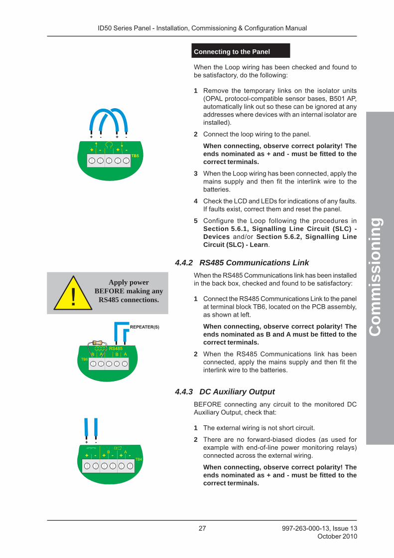
Connecting to the Panel
When the Loop wiring has been checked and found tobe satisfactory, do the following:
1 Remove the temporary links on the isolator units(OPAL protocol-compatible sensor bases, B501 AP,automatically link out so these can be ignored at anyaddresses where devices with an internal isolator areinstalled).
2 Connect the loop wiring to the panel.
When connecting, observe correct polarity! Theends nominated as + and - must be fitted to thecorrect terminals.
3 When the Loop wiring has been connected, apply themains supply and then fit the interlink wire to thebatteries.
4 Check the LCD and LEDs for indications of any faults.If faults exist, correct them and reset the panel.
5 Configure the Loop following the procedures inSection 5.6.1, Signalling Line Circuit (SLC) -Devices and/or Section 5.6.2, Signalling LineCircuit (SLC) - Learn.
4.4.2 RS485 Communications Link
When the RS485 Communications link has been installedin the back box, checked and found to be satisfactory:
1 Connect the RS485 Communications Link to the panelat terminal block TB6, located on the PCB assembly,as shown at left.
When connecting, observe correct polarity! Theends nominated as B and A must be fitted to thecorrect terminals.
2 When the RS485 Communications link has beenconnected, apply the mains supply and then fit theinterlink wire to the batteries.
4.4.3 DC Auxiliary Output
BEFORE connecting any circuit to the monitored DCAuxiliary Output, check that:
1 The external wiring is not short circuit.
2 There are no forward-biased diodes (as used forexample with end-of-line power monitoring relays)connected across the external wiring.
When connecting, observe correct polarity! Theends nominated as + and - must be fitted to thecorrect terminals.
Apply powerBEFORE making any
RS485 connections.
ID50 Series Panel - Installation, Commissioning & Configuration Manual
Co
mm
issi
on
ing
28997-263-000-13, Issue 13October 2010
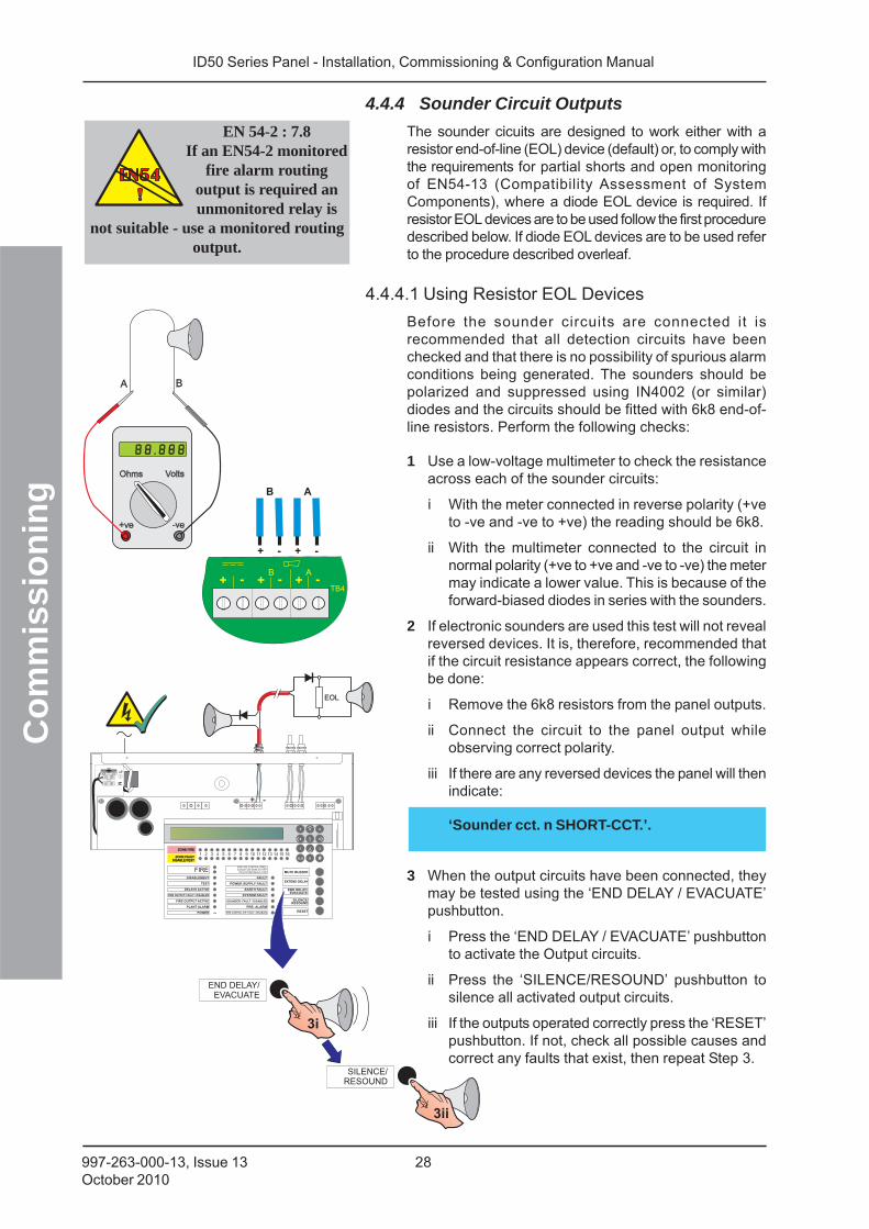
4.4.4 Sounder Circuit Outputs
The sounder cicuits are designed to work either with aresistor end-of-line (EOL) device (default) or, to comply withthe requirements for partial shorts and open monitoringof EN54-13 (Compatibility Assessment of SystemComponents), where a diode EOL device is required. Ifresistor EOL devices are to be used follow the first proceduredescribed below. If diode EOL devices are to be used referto the procedure described overleaf.
4.4.4.1 Using Resistor EOL Devices
Before the sounder circuits are connected it isrecommended that all detection circuits have beenchecked and that there is no possibility of spurious alarmconditions being generated. The sounders should bepolarized and suppressed using IN4002 (or similar)diodes and the circuits should be fitted with 6k8 end-of-line resistors. Perform the following checks:
1 Use a low-voltage multimeter to check the resistanceacross each of the sounder circuits:
i With the meter connected in reverse polarity (+veto -ve and -ve to +ve) the reading should be 6k8.
ii With the multimeter connected to the circuit innormal polarity (+ve to +ve and -ve to -ve) the metermay indicate a lower value. This is because of theforward-biased diodes in series with the sounders.
2 If electronic sounders are used this test will not revealreversed devices. It is, therefore, recommended thatif the circuit resistance appears correct, the followingbe done:
i Remove the 6k8 resistors from the panel outputs.
ii Connect the circuit to the panel output whileobserving correct polarity.
iii If there are any reversed devices the panel will thenindicate:
‘Sounder cct. n SHORT-CCT.’.
3 When the output circuits have been connected, theymay be tested using the ‘END DELAY / EVACUATE’pushbutton.
i Press the ‘END DELAY / EVACUATE’ pushbuttonto activate the Output circuits.
ii Press the ‘SILENCE/RESOUND’ pushbutton tosilence all activated output circuits.
iii If the outputs operated correctly press the ‘RESET’pushbutton. If not, check all possible causes andcorrect any faults that exist, then repeat Step 3.
NL
TB5TB4TB3
FIREDISABLEMENT
ID50 FIRE CONTROL PANELComplies with EN54-2/4 1997
Period of Manufacture 1999
FAULT
RESET
EXTEND DELAYTEST POWER SUPPLY FAULT
EARTH FAULT
POWER
PLANT ALARM
FIRE OUTPUT ACTIVE
DELAYS ACTIVE
FIRE OUTPUT: FAULT / DISABLED
FIRE CONTROL O/P: FAULT / DISABLED
PRE- ALARM
SYSTEM FAULT
SOUNDER: FAULT / DISABLED
MUTE BUZZER
SILENCE/RESOUND
END DELAY/EVACUATE
1 2 3 4 5 6 7 8 9 10 11 12 13 14 15 16ZONE FIREZONE FIRE
ZONE FAULTDISABLE/TEST
ZONE FAULTDISABLE/TEST
00..9
31
�
2
4 6
7
5�
98
+ -
EOL
EN 54-2 : 7.8If an EN54-2 monitored
fire alarm routingoutput is required anunmonitored relay is
not suitable - use a monitored routingoutput.
ID50 Series Panel - Installation, Commissioning & Configuration Manual
Co
mm
issi
on
ing
29 997-263-000-13, Issue 13October 2010
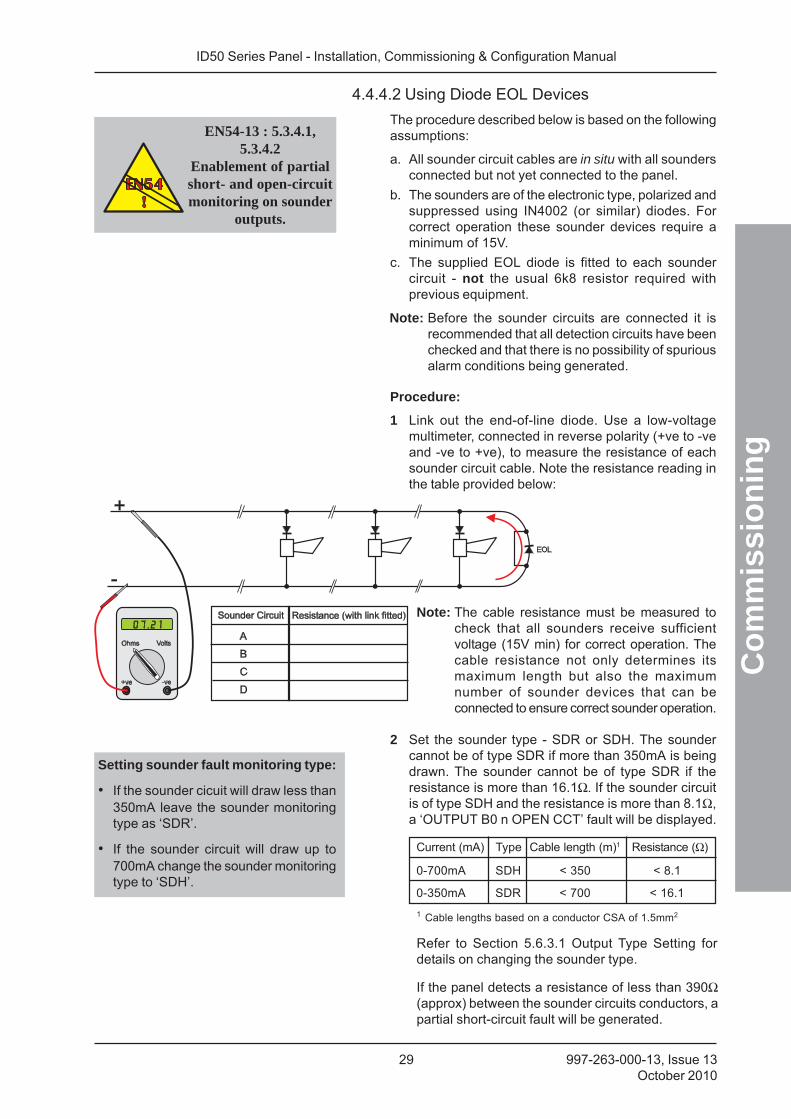
4.4.4.2 Using Diode EOL Devices
The procedure described below is based on the followingassumptions:
a. All sounder circuit cables are in situ with all soundersconnected but not yet connected to the panel.
b. The sounders are of the electronic type, polarized andsuppressed using IN4002 (or similar) diodes. Forcorrect operation these sounder devices require aminimum of 15V.
c. The supplied EOL diode is fitted to each soundercircuit - not the usual 6k8 resistor required withprevious equipment.
Note: Before the sounder circuits are connected it isrecommended that all detection circuits have beenchecked and that there is no possibility of spuriousalarm conditions being generated.
Procedure:
1 Link out the end-of-line diode. Use a low-voltagemultimeter, connected in reverse polarity (+ve to -veand -ve to +ve), to measure the resistance of eachsounder circuit cable. Note the resistance reading inthe table provided below:
Note: The cable resistance must be measured tocheck that all sounders receive sufficientvoltage (15V min) for correct operation. Thecable resistance not only determines itsmaximum length but also the maximumnumber of sounder devices that can beconnected to ensure correct sounder operation.
2 Set the sounder type - SDR or SDH. The soundercannot be of type SDR if more than 350mA is beingdrawn. The sounder cannot be of type SDR if theresistance is more than 16.1Ω. If the sounder circuitis of type SDH and the resistance is more than 8.1Ω,a ‘OUTPUT B0 n OPEN CCT’ fault will be displayed.
Current (mA) Type Cable length (m)1 Resistance (Ω)
0-700mA SDH < 350 < 8.1
0-350mA SDR < 700 < 16.1
1 Cable lengths based on a conductor CSA of 1.5mm2
Setting sounder fault monitoring type:
• If the sounder cicuit will draw less than350mA leave the sounder monitoringtype as ‘SDR’.
• If the sounder circuit will draw up to700mA change the sounder monitoringtype to ‘SDH’.
Refer to Section 5.6.3.1 Output Type Setting fordetails on changing the sounder type.
If the panel detects a resistance of less than 390Ω(approx) between the sounder circuits conductors, apartial short-circuit fault will be generated.
EN54-13 : 5.3.4.1,5.3.4.2
Enablement of partialshort- and open-circuitmonitoring on sounder
outputs.
ID50 Series Panel - Installation, Commissioning & Configuration Manual
Co
mm
issi
on
ing
30997-263-000-13, Issue 13October 2010
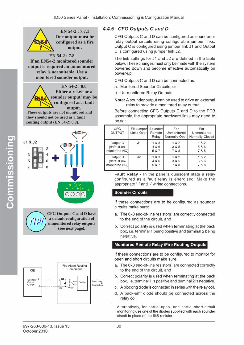
4.4.5 CFG Outputs C and D
CFG Outputs C and D can be configured as sounder orrelay output circuits using configurable jumper links.Output C is configured using jumper link J1 and OutputD is configured using jumper link J2.
The link settings for J1 and J2 are defined in the tablebelow. These changes must only be made with the systempowered down and become effective automatically onpower-up.
CFG Outputs C and D can be connected as:
a. Monitored Sounder Circuits, or
b. Un-monitored Relay Outputs
Note: A sounder output can be used to drive an externalrelay to provide a monitored relay output.
Before connecting CFG Outputs C and D to the PCBassembly, the appropriate hardware links may need tobe set.
CFG Fit Jumper Sounder/ For ForOUTPUT Links Over: Remote Unmonitored Unmonitored
Relay Normally-Open Normally-Closed
Output C J1 1 & 3 1 & 2 1 & 2(default un- 4 & 6 3 & 5 5 & 6
monitored NC) 5 & 7 7 & 8 7 & 8
Output D J2 1 & 3 1 & 2 1 & 2(default un- 4 & 6 3 & 5 5 & 6
monitored NO) 5 & 7 7 & 8 7 & 8
Fault Relay - In the panel’s quiescent state a relayconfigured as a fault relay is energised. Make theappropriate ‘+’ and ‘-’ wiring connections.
Sounder Circuits
If these connections are to be configured as soundercircuits make sure:
a. The 6k8 end-of-line resistors1 are correctly connectedto the end of the circuit, and
b. Correct polarity is used when terminating at the backbox, i.e. terminal 1 being positive and terminal 2 beingnegative.
Monitored Remote Relay /Fire Routing Outputs
If these connections are to be configured to monitor foropen and short circuits make sure:
a. The 6k8 end-of-line resistors1 are connected correctlyto the end of the circuit, and
b. Correct polarity is used when terminating at the backbox, i.e. terminal 1 is positive and terminal 2 is negative.
c. A blocking diode is connected in series with the relay coil.
d. A back-emf diode should be connected across therelay coil.
1
J1 & J2
3
5
7
2
4
6
8
CFG Outputs C and D havea default configuration ofunmonitored relay outputs
(see next page).
1 Alternatively, for partial-open- and partial-short-circuitmonitoring use one of the diodes supplied with each soundercircuit in place of the 6k8 resistor.
EN 54-2 : 7.7.1One output must beconfigured as a fire
output.
EN 54-2 : 7.8If an EN54-2 monitored sounder
output is required an unmonitoredrelay is not suitable. Use amonitored sounder output.
EN 54-2 : 8.8Either a relay1 or a
sounder output1 may beconfigured as a fault
output. 1 These outputs are not monitored and
they should not be used as a faultrouting output (EN 54-2: 8.9).
ID50 Series Panel - Installation, Commissioning & Configuration Manual
Co
mm
issi
on
ing
31 997-263-000-13, Issue 13October 2010
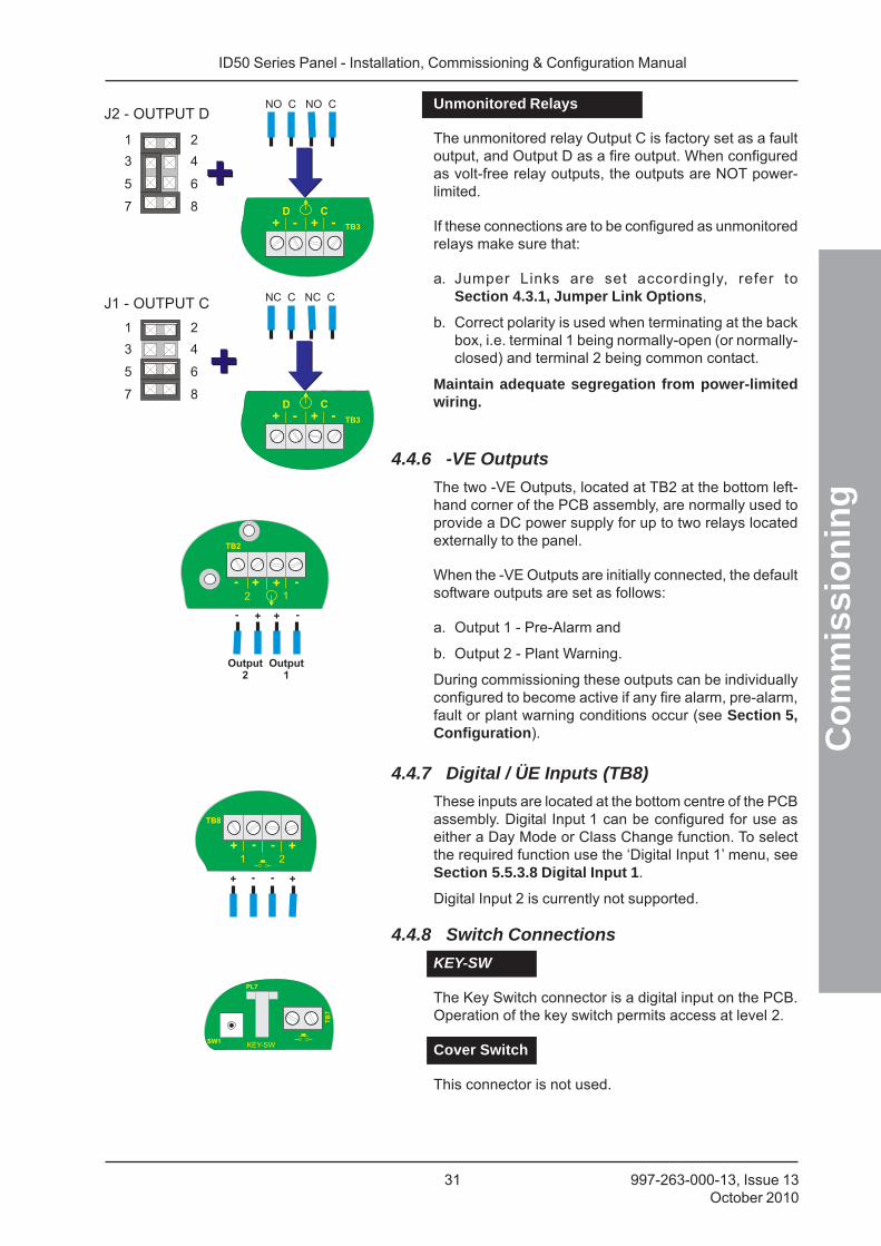
Unmonitored Relays
The unmonitored relay Output C is factory set as a faultoutput, and Output D as a fire output. When configuredas volt-free relay outputs, the outputs are NOT power-limited.
If these connections are to be configured as unmonitoredrelays make sure that:
a. Jumper Links are set accordingly, refer toSection 4.3.1, Jumper Link Options,
b. Correct polarity is used when terminating at the backbox, i.e. terminal 1 being normally-open (or normally-closed) and terminal 2 being common contact.
Maintain adequate segregation from power-limitedwiring.
4.4.6 -VE Outputs
The two -VE Outputs, located at TB2 at the bottom left-hand corner of the PCB assembly, are normally used toprovide a DC power supply for up to two relays locatedexternally to the panel.
When the -VE Outputs are initially connected, the defaultsoftware outputs are set as follows:
a. Output 1 - Pre-Alarm and
b. Output 2 - Plant Warning.
During commissioning these outputs can be individuallyconfigured to become active if any fire alarm, pre-alarm,fault or plant warning conditions occur (see Section 5,Configuration).
4.4.7 Digital / ÜE Inputs (TB8)
These inputs are located at the bottom centre of the PCBassembly. Digital Input 1 can be configured for use aseither a Day Mode or Class Change function. To selectthe required function use the ‘Digital Input 1’ menu, seeSection 5.5.3.8 Digital Input 1.
Digital Input 2 is currently not supported.
4.4.8 Switch Connections
KEY-SW
The Key Switch connector is a digital input on the PCB.Operation of the key switch permits access at level 2.
Cover Switch
This connector is not used.
1
3
5
7
2
4
6
8
1
3
5
7
2
4
6
8
J2 - OUTPUT D
J1 - OUTPUT C
ID50 Series Panel - Installation, Commissioning & Configuration Manual
Co
mm
issi
on
ing
32997-263-000-13, Issue 13October 2010
POWER
PLANT ALARM
RESET
4
FIREDISABLEMENT FAULT
TEST POWER SUPPLY FAULT
EARTH FAULT
POWER
PLANT ALARM
FIRE OUTPUT ACTIVE
DELAYS ACTIVE
FIRE OUTPUT: FAULT / DISABLED
FIRE CONTROL O/P: FAULT / DISABLED
PRE- ALARM
SYSTEM FAULT
SOUNDER: FAULT / DISABLED
Status: NORMALSat 05/01/2002 00:00:00
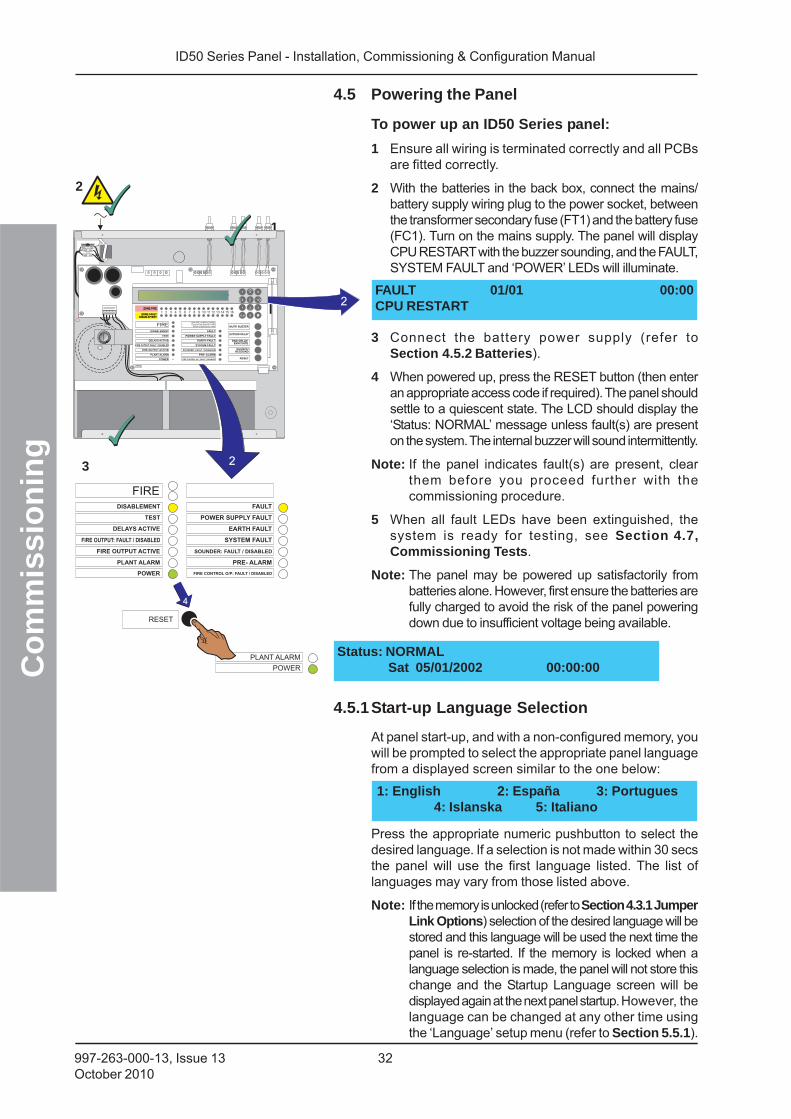
4.5 Powering the Panel
To power up an ID50 Series panel:
1 Ensure all wiring is terminated correctly and all PCBsare fitted correctly.
2 With the batteries in the back box, connect the mains/battery supply wiring plug to the power socket, betweenthe transformer secondary fuse (FT1) and the battery fuse(FC1). Turn on the mains supply. The panel will displayCPU RESTART with the buzzer sounding, and the FAULT,SYSTEM FAULT and ‘POWER’ LEDs will illuminate.
3 Connect the battery power supply (refer toSection 4.5.2 Batteries).
4 When powered up, press the RESET button (then enteran appropriate access code if required). The panel shouldsettle to a quiescent state. The LCD should display the‘Status: NORMAL’ message unless fault(s) are presenton the system. The internal buzzer will sound intermittently.
Note: If the panel indicates fault(s) are present, clearthem before you proceed further with thecommissioning procedure.
5 When all fault LEDs have been extinguished, thesystem is ready for testing, see Section 4.7,Commissioning Tests.
Note: The panel may be powered up satisfactorily frombatteries alone. However, first ensure the batteries arefully charged to avoid the risk of the panel poweringdown due to insufficient voltage being available.
3
2
1
4.5.1Start-up Language Selection
At panel start-up, and with a non-configured memory, youwill be prompted to select the appropriate panel languagefrom a displayed screen similar to the one below:
Press the appropriate numeric pushbutton to select thedesired language. If a selection is not made within 30 secsthe panel will use the first language listed. The list oflanguages may vary from those listed above.
Note: If the memory is unlocked (refer to Section 4.3.1 JumperLink Options) selection of the desired language will bestored and this language will be used the next time thepanel is re-started. If the memory is locked when alanguage selection is made, the panel will not store thischange and the Startup Language screen will bedisplayed again at the next panel startup. However, thelanguage can be changed at any other time usingthe ‘Language’ setup menu (refer to Section 5.5.1).
1: English 2: España 3: Portugues4: Islanska 5: Italiano
NL
2
2
FIREDISABLEMENT
ID50 FIRE CONTROL PANELComplies with EN54-2/4 1997
Period of Manufacture 1999
FAULT
RESET
EXTEND DELAYTEST POWER SUPPLY FAULT
EARTH FAULT
POWER
PLANT ALARM
FIRE OUTPUT ACTIVE
DELAYS ACTIVE
FIRE OUTPUT: FAULT / DISABLED
FIRE CONTROL O/P: FAULT / DISABLED
PRE- ALARM
SYSTEM FAULT
SOUNDER: FAULT / DISABLED
MUTE BUZZER
SILENCE/RESOUND
END DELAY/EVACUATE
1 2 3 4 5 6 7 8 9 10 11 12 13 14 15 16ZONE FIREZONE FIRE
ZONE FAULTDISABLE/TEST
ZONE FAULTDISABLE/TEST
00..9
31
�
2
4 6
7
5�
98 FAULT 01/01 00:00CPU RESTART
ID50 Series Panel - Installation, Commissioning & Configuration Manual
Co
mm
issi
on
ing
33 997-263-000-13, Issue 13October 2010
NL
1 2 3 4 5 6 7 8 9 10 11 12 13 14 15 16ZONE FIREZONE FIRE
ZONE FAULTDISABLE/TEST
ZONE FAULTDISABLE/TEST
00..9
31
�
2
4 6
7
5�
98
MUTE BUZZER
RESET
EXTEND DELAY
END DELAY/EVACUATE
SILENCE/RESOUND
FIREDISABLEMENT FAULT
TEST POWER SUPPLY FAULT
EARTH FAULT
POWER
PLANT ALARM
FIRE OUTPUT ACTIVE
DELAYS ACTIVE
FIRE OUTPUT: FAULT / DISABLED
FIRE CONTROL O/P: FAULT / DISABLED
PRE- ALARM
SYSTEM FAULT
SOUNDER: FAULT / DISABLED
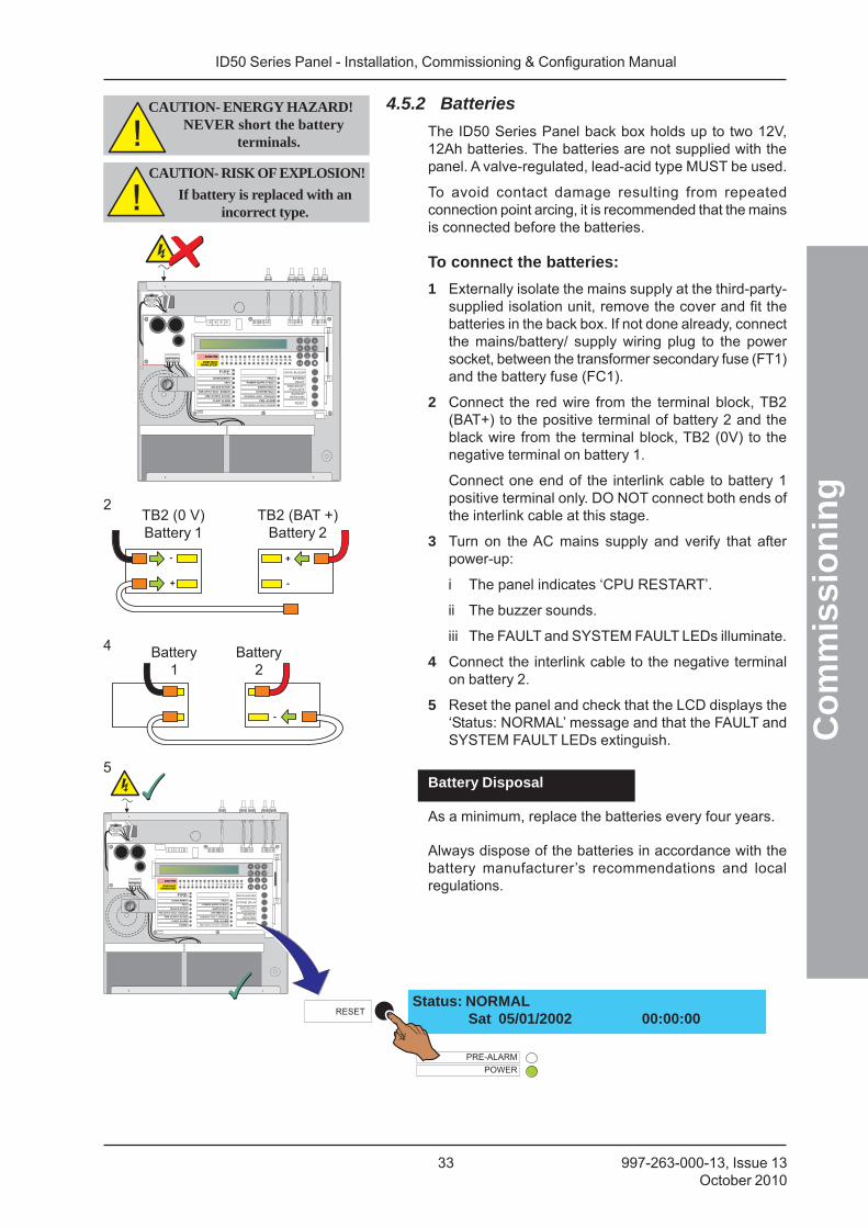
4.5.2 Batteries
The ID50 Series Panel back box holds up to two 12V,12Ah batteries. The batteries are not supplied with thepanel. A valve-regulated, lead-acid type MUST be used.
To avoid contact damage resulting from repeatedconnection point arcing, it is recommended that the mainsis connected before the batteries.
To connect the batteries:
1 Externally isolate the mains supply at the third-party-supplied isolation unit, remove the cover and fit thebatteries in the back box. If not done already, connectthe mains/battery/ supply wiring plug to the powersocket, between the transformer secondary fuse (FT1)and the battery fuse (FC1).
2 Connect the red wire from the terminal block, TB2(BAT+) to the positive terminal of battery 2 and theblack wire from the terminal block, TB2 (0V) to thenegative terminal on battery 1.
Connect one end of the interlink cable to battery 1positive terminal only. DO NOT connect both ends ofthe interlink cable at this stage.
3 Turn on the AC mains supply and verify that afterpower-up:
i The panel indicates ‘CPU RESTART’.
ii The buzzer sounds.
iii The FAULT and SYSTEM FAULT LEDs illuminate.
4 Connect the interlink cable to the negative terminalon battery 2.
5 Reset the panel and check that the LCD displays the‘Status: NORMAL’ message and that the FAULT andSYSTEM FAULT LEDs extinguish.
Battery Disposal
As a minimum, replace the batteries every four years.
Always dispose of the batteries in accordance with thebattery manufacturer’s recommendations and localregulations.
Status: NORMALSat 05/01/2002 00:00:00
CAUTION- ENERGY HAZARD!NEVER short the battery
terminals.
2
4
5
TB2 (0 V)Battery 1
TB2 (BAT +)Battery 2
Battery1
Battery2
NL
1 2 3 4 5 6 7 8 9 10 11 12 13 14 15 16ZONE FIREZONE FIRE
ZONE FAULTDISABLE/TEST
ZONE FAULTDISABLE/TEST
00..9
31
�
2
4 6
7
5�
98
MUTE BUZZER
RESET
EXTENDDELAY
END DELAY/EVACUATE
SILENCE/RESOUND
FIREDISABLEMENT FAULT
TEST POWER SUPPLY FAULT
EARTH FAULT
POWER
PLANT ALARM
FIRE OUTPUT ACTIVE
DELAYS ACTIVE
FIRE OUTPUT: FAULT / DISABLED
FIRE CONTROL O/P: FAULT / DISABLED
PRE- ALARM
SYSTEM FAULT
SOUNDER: FAULT / DISABLED
CAUTION- RISK OF EXPLOSION!
If battery is replaced with anincorrect type.
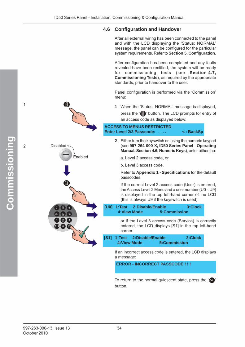
ID50 Series Panel - Installation, Commissioning & Configuration Manual
Co
mm
issi
on
ing
34997-263-000-13, Issue 13October 2010
4.6 Configuration and Handover
After all external wiring has been connected to the paneland with the LCD displaying the ‘Status: NORMAL’message, the panel can be configured for the particularsystem requirements. Refer to Section 5, Configuration.
After configuration has been completed and any faultsrevealed have been rectified, the system will be readyfor commissioning tests (see Section 4.7,Commissioning Tests), as required by the appropriatestandards, prior to handover to the user.
Panel configuration is performed via the ‘Commission’menu:
1 When the ‘Status: NORMAL’ message is displayed,
press the ‘ ’ button. The LCD prompts for entry of
an access code as displayed below:
2 Either turn the keyswitch or, using the numeric keypad(see 997-264-000-X, ID50 Series Panel - OperatingManual, Section 4.6, Numeric Keys), enter either the:
a. Level 2 access code, or
b. Level 3 access code.
Refer to Appendix 1 - Specifications for the defaultpasscodes.
If the correct Level 2 access code (User) is entered,the Access Level 2 Menu and a user number (U0 - U9)is displayed in the top left-hand corner of the LCD(this is always U9 if the keyswitch is used):
or if the Level 3 access code (Service) is correctlyentered, the LCD displays [S1] in the top left-handcorner:
If an incorrect access code is entered, the LCD displaysa message:
To return to the normal quiescent state, press the ‘ 4 ’
button.
ACCESS TO MENUS RESTRICTEDEnter Level 2/3 Passcode: . . . . < : BackSp
[U0] 1:Test 2:Disable/Enable 3:Clock4:View Mode 5:Commission
[S1] 1:Test 2:Disable/Enable 3:Clock4:View Mode 5:Commission
ERROR - INCORRECT PASSCODE ! ! !
1
2
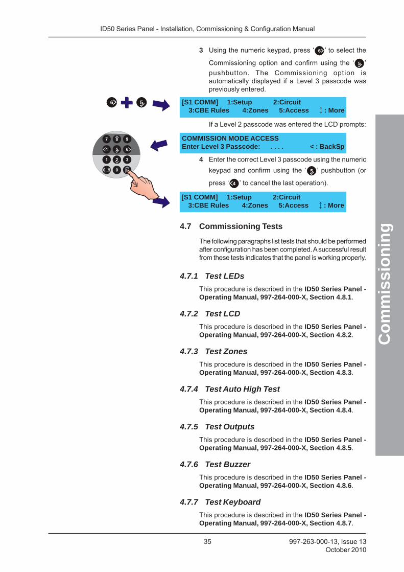
ID50 Series Panel - Installation, Commissioning & Configuration Manual
Co
mm
issi
on
ing
35 997-263-000-13, Issue 13October 2010
3 Using the numeric keypad, press ‘ 6 ’ to select the
Commissioning option and confirm using the ‘ 5 ’
pushbutton. The Commissioning option isautomatically displayed if a Level 3 passcode waspreviously entered.
If a Level 2 passcode was entered the LCD prompts:
4 Enter the correct Level 3 passcode using the numeric
keypad and confirm using the ‘ 5 ’ pushbutton (or
press ‘ 4 ’ to cancel the last operation).
4.7 Commissioning Tests
The following paragraphs list tests that should be performedafter configuration has been completed. A successful resultfrom these tests indicates that the panel is working properly.
4.7.1 Test LEDs
This procedure is described in the ID50 Series Panel -Operating Manual, 997-264-000-X, Section 4.8.1.
4.7.2 Test LCD
This procedure is described in the ID50 Series Panel -Operating Manual, 997-264-000-X, Section 4.8.2.
4.7.3 Test Zones
This procedure is described in the ID50 Series Panel -Operating Manual, 997-264-000-X, Section 4.8.3.
4.7.4 Test Auto High Test
This procedure is described in the ID50 Series Panel -Operating Manual, 997-264-000-X, Section 4.8.4.
4.7.5 Test Outputs
This procedure is described in the ID50 Series Panel -Operating Manual, 997-264-000-X, Section 4.8.5.
4.7.6 Test Buzzer
This procedure is described in the ID50 Series Panel -Operating Manual, 997-264-000-X, Section 4.8.6.
4.7.7 Test Keyboard
This procedure is described in the ID50 Series Panel -Operating Manual, 997-264-000-X, Section 4.8.7.
[S1 COMM] 1:Setup 2:Circuit3:CBE Rules 4:Zones 5:Access : More
COMMISSION MODE ACCESSEnter Level 3 Passcode: . . . . < : BackSp
[S1 COMM] 1:Setup 2:Circuit3:CBE Rules 4:Zones 5:Access : More
6 5
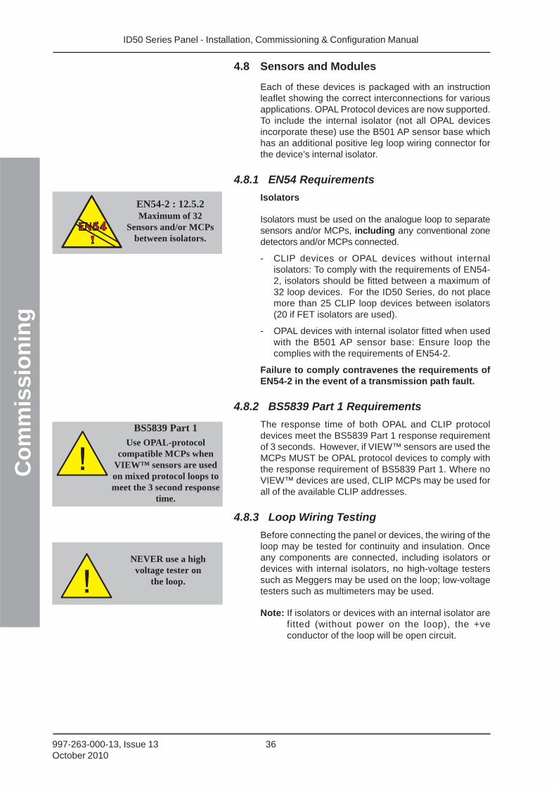
ID50 Series Panel - Installation, Commissioning & Configuration Manual
Co
mm
issi
on
ing
36997-263-000-13, Issue 13October 2010
4.8 Sensors and Modules
Each of these devices is packaged with an instructionleaflet showing the correct interconnections for variousapplications. OPAL Protocol devices are now supported.To include the internal isolator (not all OPAL devicesincorporate these) use the B501 AP sensor base whichhas an additional positive leg loop wiring connector forthe device’s internal isolator.
4.8.1 EN54 Requirements
Isolators
Isolators must be used on the analogue loop to separatesensors and/or MCPs, including any conventional zonedetectors and/or MCPs connected.
- CLIP devices or OPAL devices without internalisolators: To comply with the requirements of EN54-2, isolators should be fitted between a maximum of32 loop devices. For the ID50 Series, do not placemore than 25 CLIP loop devices between isolators(20 if FET isolators are used).
- OPAL devices with internal isolator fitted when usedwith the B501 AP sensor base: Ensure loop thecomplies with the requirements of EN54-2.
Failure to comply contravenes the requirements ofEN54-2 in the event of a transmission path fault.
4.8.2 BS5839 Part 1 Requirements
The response time of both OPAL and CLIP protocoldevices meet the BS5839 Part 1 response requirementof 3 seconds. However, if VIEW™ sensors are used theMCPs MUST be OPAL protocol devices to comply withthe response requirement of BS5839 Part 1. Where noVIEW™ devices are used, CLIP MCPs may be used forall of the available CLIP addresses.
4.8.3 Loop Wiring Testing
Before connecting the panel or devices, the wiring of theloop may be tested for continuity and insulation. Onceany components are connected, including isolators ordevices with internal isolators, no high-voltage testerssuch as Meggers may be used on the loop; low-voltagetesters such as multimeters may be used.
Note: If isolators or devices with an internal isolator arefitted (without power on the loop), the +veconductor of the loop will be open circuit.
EN54-2 : 12.5.2Maximum of 32
Sensors and/or MCPsbetween isolators.
NEVER use a highvoltage tester on
the loop.
BS5839 Part 1
Use OPAL-protocolcompatible MCPs when
VIEW™ sensors are usedon mixed protocol loops tomeet the 3 second response
time.
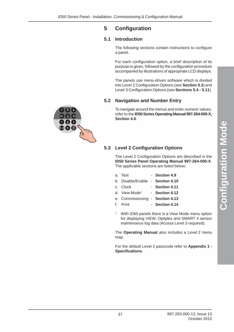
ID50 Series Panel - Installation, Commissioning & Configuration Manual
Co
nfi
gu
rati
on
Mo
de
37 997-263-000-13, Issue 13October 2010
5 Configuration
5.1 Introduction
The following sections contain instructions to configurea panel.
For each configuration option, a brief description of itspurpose is given, followed by the configuration procedureaccompanied by illustrations of appropriate LCD displays.
The panels use menu-driven software which is dividedinto Level 2 Configuration Options (see Section 5.3) andLevel 3 Configuration Options (see Sections 5.4 - 5.11).
5.2 Navigation and Number Entry
To navigate around the menus and enter numeric values,refer to the ID50 Series Operating Manual 997-264-000-X,Section 4.6.
5.3 Level 2 Configuration Options
The Level 2 Configuration Options are described in theID50 Series Panel Operating Manual 997-264-000-X.The applicable sections are listed below:
a. Test - Section 4.9
b. Disable/Enable - Section 4.10
c. Clock - Section 4.11
d. View Mode1 - Section 4.12
e. Commissioning - Section 4.13
f. Print - Section 4.14
1 With ID60 panels there is a View Mode menu optionfor displaying VIEW, Optiplex and SMART 4 sensormaintenance log data (Access Level 3 required).
The Operating Manual also includes a Level 2 menumap.
For the default Level 2 passcode refer to Appendix 1 -Specifications.
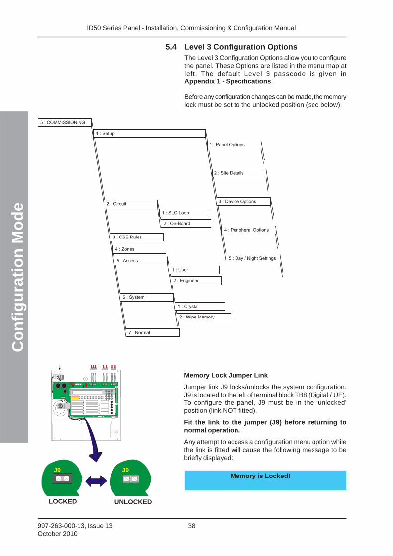
ID50 Series Panel - Installation, Commissioning & Configuration ManualC
on
fig
ura
tio
n M
od
e
38997-263-000-13, Issue 13October 2010
MEMMEM
5.4 Level 3 Configuration OptionsThe Level 3 Configuration Options allow you to configurethe panel. These Options are listed in the menu map atleft. The default Level 3 passcode is given inAppendix 1 - Specifications.
Before any configuration changes can be made, the memorylock must be set to the unlocked position (see below).
Memory Lock Jumper Link
Jumper link J9 locks/unlocks the system configuration.J9 is located to the left of terminal block TB8 (Digital / ÜE).To configure the panel, J9 must be in the ‘unlocked’position (link NOT fitted).
Fit the link to the jumper (J9) before returning tonormal operation.
Any attempt to access a configuration menu option whilethe link is fitted will cause the following message to bebriefly displayed:
Memory is Locked!J9J9
LOCKED UNLOCKED
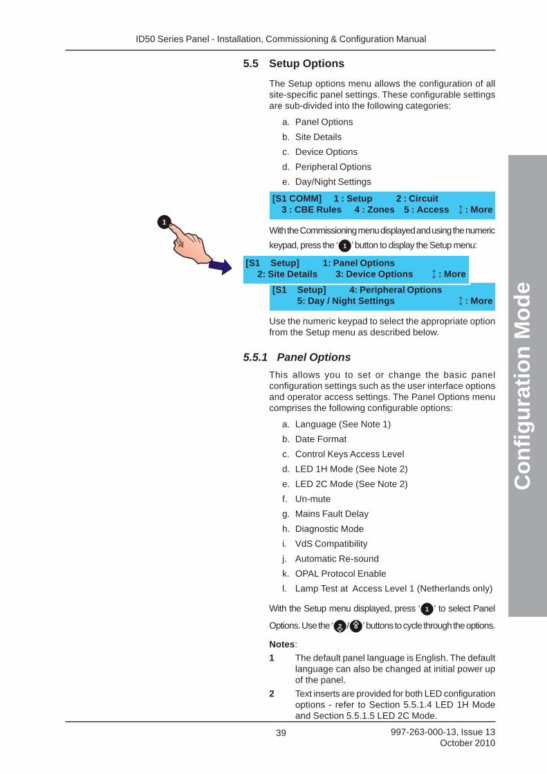
ID50 Series Panel - Installation, Commissioning & Configuration Manual
Co
nfi
gu
rati
on
Mo
de
39 997-263-000-13, Issue 13October 2010
5.5 Setup Options
The Setup options menu allows the configuration of allsite-specific panel settings. These configurable settingsare sub-divided into the following categories:
a. Panel Options
b. Site Details
c. Device Options
d. Peripheral Options
e. Day/Night Settings
With the Commissioning menu displayed and using the numeric
keypad, press the ‘ 1 ’ button to display the Setup menu:
Use the numeric keypad to select the appropriate optionfrom the Setup menu as described below.
5.5.1 Panel Options
This allows you to set or change the basic panelconfiguration settings such as the user interface optionsand operator access settings. The Panel Options menucomprises the following configurable options:
a. Language (See Note 1)
b. Date Format
c. Control Keys Access Level
d. LED 1H Mode (See Note 2)
e. LED 2C Mode (See Note 2)
f. Un-mute
g. Mains Fault Delay
h. Diagnostic Mode
i. VdS Compatibility
j. Automatic Re-sound
k. OPAL Protocol Enable
l. Lamp Test at Access Level 1 (Netherlands only)
With the Setup menu displayed, press ‘ 1 ’ to select Panel
Options. Use the ‘ 2 / 8 ’ buttons to cycle through the options.
Notes:
1 The default panel language is English. The defaultlanguage can also be changed at initial power upof the panel.
2 Text inserts are provided for both LED configurationoptions - refer to Section 5.5.1.4 LED 1H Modeand Section 5.5.1.5 LED 2C Mode.
[S1 COMM] 1 : Setup 2 : Circuit3 : CBE Rules 4 : Zones 5 : Access : More
[S1 Setup] 4: Peripheral Options5: Day / Night Settings : More
[S1 Setup] 1: Panel Options2: Site Details 3: Device Options : More
1
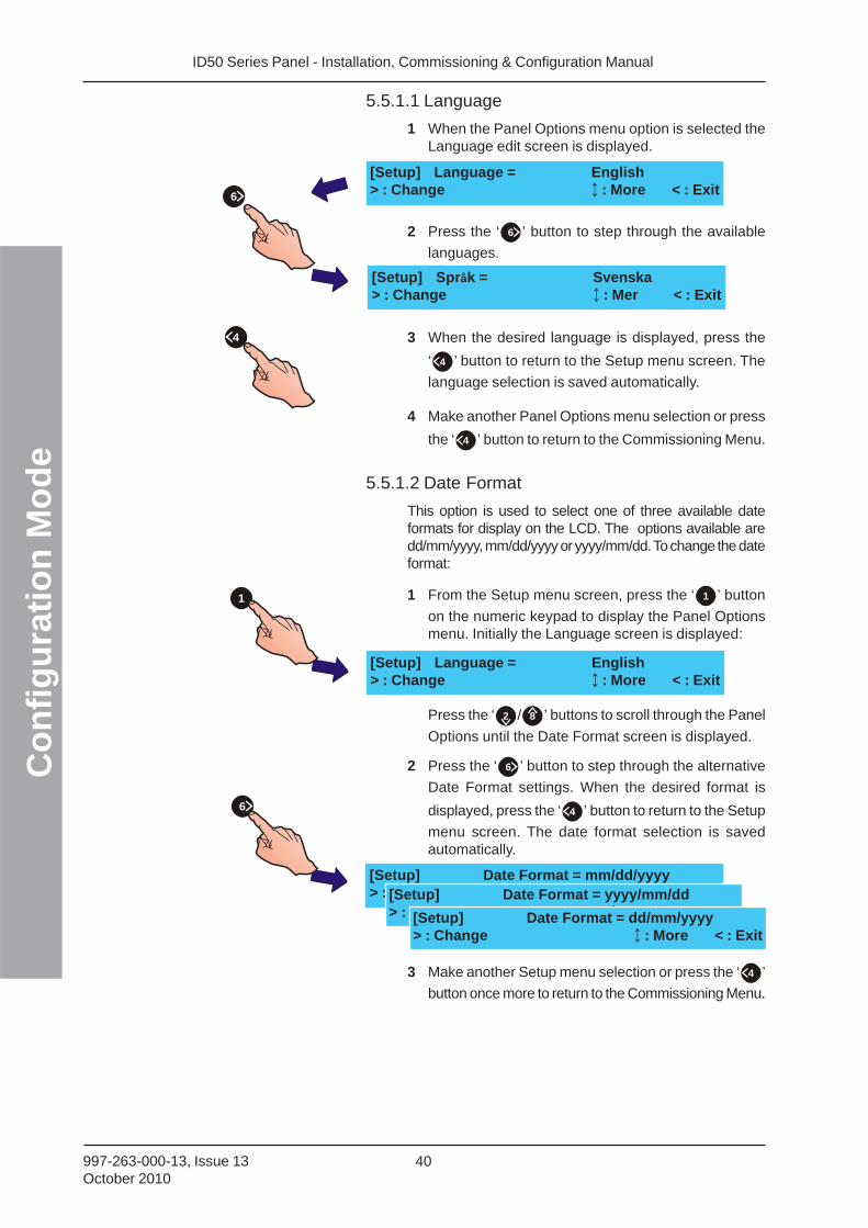
ID50 Series Panel - Installation, Commissioning & Configuration ManualC
on
fig
ura
tio
n M
od
e
40997-263-000-13, Issue 13October 2010
1
6
[Setup] Språk = Svenska> : Change : Mer < : Exit
6
5.5.1.1 Language
1 When the Panel Options menu option is selected theLanguage edit screen is displayed.
2 Press the ‘ 6 ’ button to step through the available
languages.
3 When the desired language is displayed, press the
‘ 4 ’ button to return to the Setup menu screen. The
language selection is saved automatically.
4 Make another Panel Options menu selection or press
the ‘ 4 ’ button to return to the Commissioning Menu.
5.5.1.2 Date Format
This option is used to select one of three available dateformats for display on the LCD. The options available aredd/mm/yyyy, mm/dd/yyyy or yyyy/mm/dd. To change the dateformat:
1 From the Setup menu screen, press the ‘ 1 ’ button
on the numeric keypad to display the Panel Optionsmenu. Initially the Language screen is displayed:
Press the ‘ 2 / 8 ’ buttons to scroll through the Panel
Options until the Date Format screen is displayed.
2 Press the ‘ 6 ’ button to step through the alternative
Date Format settings. When the desired format is
displayed, press the ‘ 4 ’ button to return to the Setup
menu screen. The date format selection is savedautomatically.
3 Make another Setup menu selection or press the ‘ 4 ’
button once more to return to the Commissioning Menu.
[Setup] Language = English> : Change : More < : Exit
[Setup] Language = English> : Change : More < : Exit
[Setup] Date Format = mm/dd/yyyy> : Change : More < : Exit[Setup] Date Format = yyyy/mm/dd
> : Change : More < : Exit[Setup] Date Format = dd/mm/yyyy> : Change : More < : Exit
4
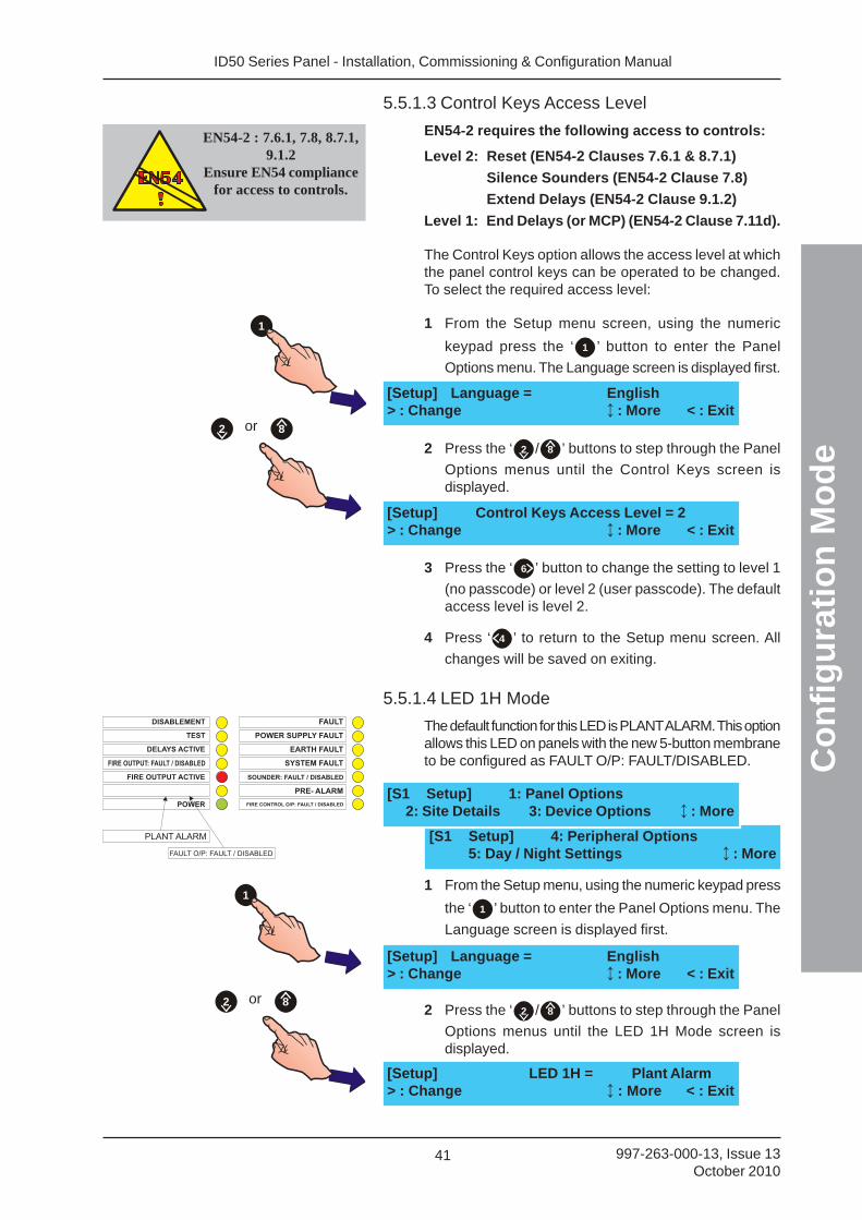
ID50 Series Panel - Installation, Commissioning & Configuration Manual
Co
nfi
gu
rati
on
Mo
de
41 997-263-000-13, Issue 13October 2010
1
5.5.1.3 Control Keys Access Level
EN54-2 requires the following access to controls:
Level 2: Reset (EN54-2 Clauses 7.6.1 & 8.7.1)
Silence Sounders (EN54-2 Clause 7.8)
Extend Delays (EN54-2 Clause 9.1.2)
Level 1: End Delays (or MCP) (EN54-2 Clause 7.11d).
The Control Keys option allows the access level at whichthe panel control keys can be operated to be changed.To select the required access level:
1 From the Setup menu screen, using the numeric
keypad press the ‘ 1 ’ button to enter the Panel
Options menu. The Language screen is displayed first.
2 Press the ‘ 2 / 8 ’ buttons to step through the Panel
Options menus until the Control Keys screen isdisplayed.
3 Press the ‘ 6 ’ button to change the setting to level 1
(no passcode) or level 2 (user passcode). The defaultaccess level is level 2.
4 Press ‘ 4 ’ to return to the Setup menu screen. All
changes will be saved on exiting.
5.5.1.4 LED 1H Mode
The default function for this LED is PLANT ALARM. This optionallows this LED on panels with the new 5-button membraneto be configured as FAULT O/P: FAULT/DISABLED.
1 From the Setup menu, using the numeric keypad press
the ‘ 1 ’ button to enter the Panel Options menu. The
Language screen is displayed first.
2 Press the ‘ 2 / 8 ’ buttons to step through the Panel
Options menus until the LED 1H Mode screen isdisplayed.
[Setup] Control Keys Access Level = 2> : Change : More < : Exit
[Setup] Language = English> : Change : More < : Exit
or 82
EN54-2 : 7.6.1, 7.8, 8.7.1,9.1.2
Ensure EN54 compliancefor access to controls.
PLANT ALARM
FAULT O/P: FAULT / DISABLED
DISABLEMENT FAULT
TEST POWER SUPPLY FAULT
EARTH FAULT
POWER
FIRE OUTPUT ACTIVE
DELAYS ACTIVE
FIRE OUTPUT: FAULT / DISABLED
FIRE CONTROL O/P: FAULT / DISABLED
PRE- ALARM
SYSTEM FAULT
SOUNDER: FAULT / DISABLED
1
or 82
[S1 Setup] 4: Peripheral Options5: Day / Night Settings : More
[S1 Setup] 1: Panel Options2: Site Details 3: Device Options : More
[Setup] Language = English> : Change : More < : Exit
[Setup] LED 1H = Plant Alarm> : Change : More < : Exit
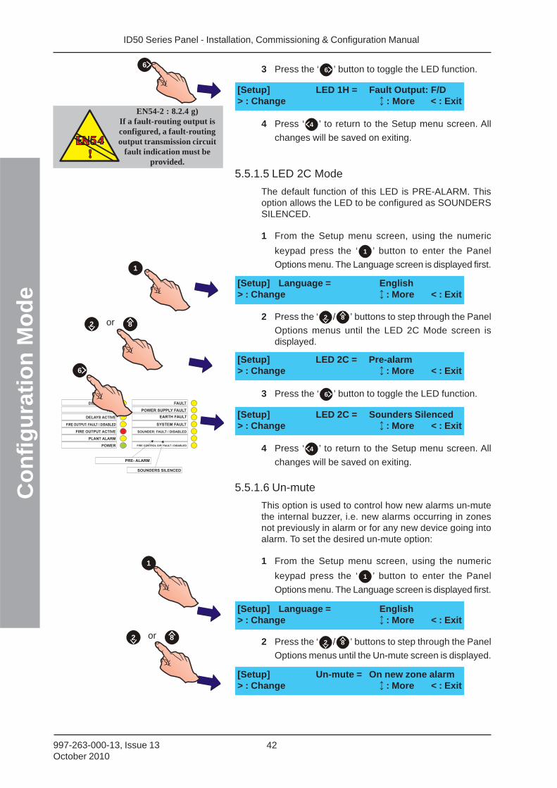
ID50 Series Panel - Installation, Commissioning & Configuration ManualC
on
fig
ura
tio
n M
od
e
42997-263-000-13, Issue 13October 2010
DISABLEMENT FAULT
TEST POWER SUPPLY FAULT
EARTH FAULT
POWER
PLANT ALARM
FIRE OUTPUT ACTIVE
DELAYS ACTIVE
FIRE OUTPUT: FAULT / DISABLED
FIRE CONTROL O/P: FAULT / DISABLED
PRE- ALARM
SYSTEM FAULT
SOUNDER: FAULT / DISABLED
SOUNDERS SILENCED
3 Press the ‘ 6 ’ button to toggle the LED function.
4 Press ‘ 4 ’ to return to the Setup menu screen. All
changes will be saved on exiting.
5.5.1.5 LED 2C Mode
The default function of this LED is PRE-ALARM. Thisoption allows the LED to be configured as SOUNDERSSILENCED.
1 From the Setup menu screen, using the numeric
keypad press the ‘ 1 ’ button to enter the Panel
Options menu. The Language screen is displayed first.
2 Press the ‘ 2 / 8 ’ buttons to step through the Panel
Options menus until the LED 2C Mode screen isdisplayed.
3 Press the ‘ 6 ’ button to toggle the LED function.
4 Press ‘ 4 ’ to return to the Setup menu screen. All
changes will be saved on exiting.
5.5.1.6 Un-mute
This option is used to control how new alarms un-mutethe internal buzzer, i.e. new alarms occurring in zonesnot previously in alarm or for any new device going intoalarm. To set the desired un-mute option:
1 From the Setup menu screen, using the numeric
keypad press the ‘ 1 ’ button to enter the Panel
Options menu. The Language screen is displayed first.
2 Press the ‘ 2 / 8 ’ buttons to step through the Panel
Options menus until the Un-mute screen is displayed.
[Setup] LED 1H = Fault Output: F/D> : Change : More < : Exit
[Setup] Language = English> : Change : More < : Exit
[Setup] LED 2C = Pre-alarm> : Change : More < : Exit
[Setup] LED 2C = Sounders Silenced> : Change : More < : Exit
[Setup] Language = English> : Change : More < : Exit
[Setup] Un-mute = On new zone alarm> : Change : More < : Exit
1
or 82
6
6
1
or 82
EN54-2 : 8.2.4 g)If a fault-routing output isconfigured, a fault-routingoutput transmission circuit
fault indication must beprovided.
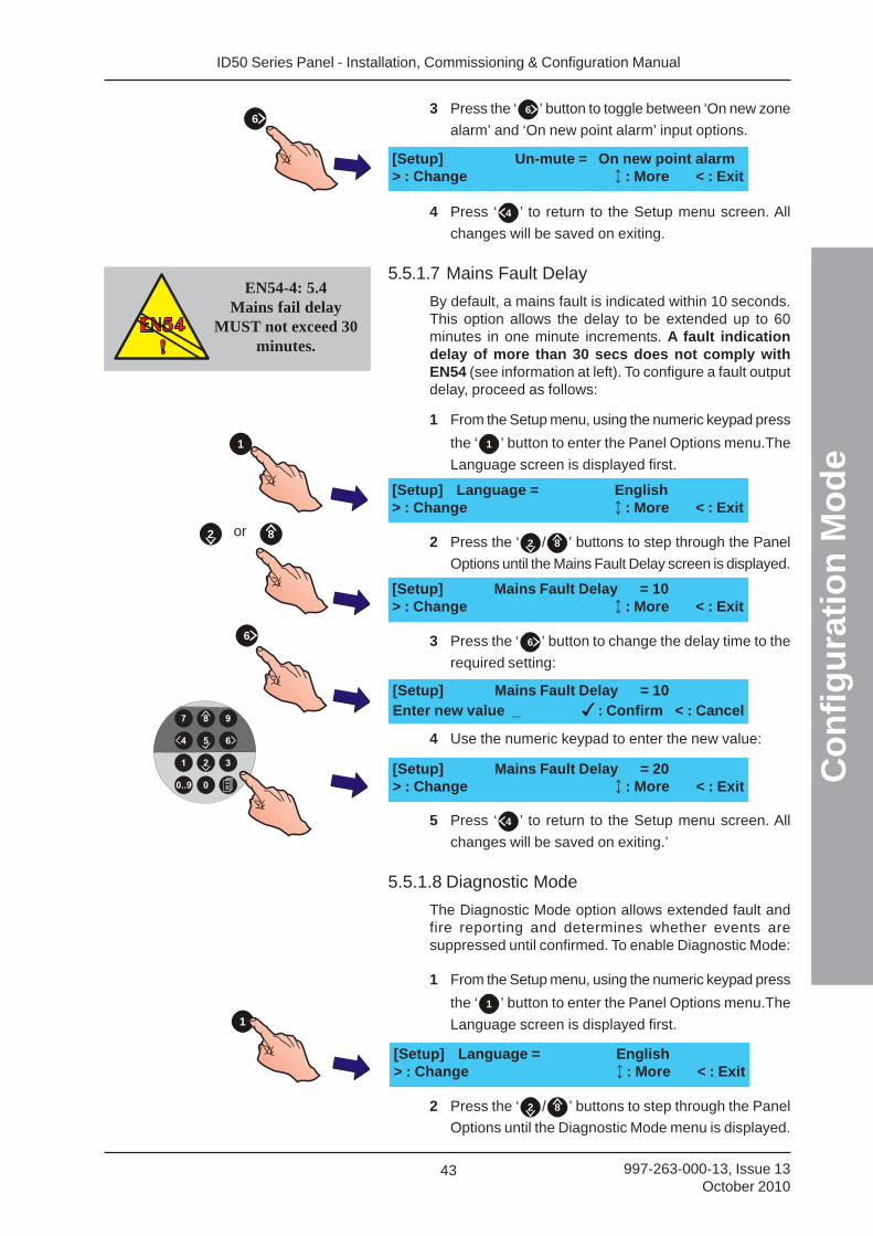
ID50 Series Panel - Installation, Commissioning & Configuration Manual
Co
nfi
gu
rati
on
Mo
de
43 997-263-000-13, Issue 13October 2010
3 Press the ‘ 6 ’ button to toggle between ‘On new zone
alarm’ and ‘On new point alarm’ input options.
4 Press ‘ 4 ’ to return to the Setup menu screen. All
changes will be saved on exiting.
5.5.1.7 Mains Fault Delay
By default, a mains fault is indicated within 10 seconds.This option allows the delay to be extended up to 60minutes in one minute increments. A fault indicationdelay of more than 30 secs does not comply withEN54 (see information at left). To configure a fault outputdelay, proceed as follows:
1 From the Setup menu, using the numeric keypad press
the ‘ 1 ’ button to enter the Panel Options menu.The
Language screen is displayed first.
2 Press the ‘ 2 / 8 ’ buttons to step through the Panel
Options until the Mains Fault Delay screen is displayed.
3 Press the ‘ 6 ’ button to change the delay time to the
required setting:
4 Use the numeric keypad to enter the new value:
5 Press ‘ 4 ’ to return to the Setup menu screen. All
changes will be saved on exiting.’
5.5.1.8 Diagnostic Mode
The Diagnostic Mode option allows extended fault andfire reporting and determines whether events aresuppressed until confirmed. To enable Diagnostic Mode:
1 From the Setup menu, using the numeric keypad press
the ‘ 1 ’ button to enter the Panel Options menu.The
Language screen is displayed first.
2 Press the ‘ 2 / 8 ’ buttons to step through the Panel
Options until the Diagnostic Mode menu is displayed.
[Setup] Un-mute = On new point alarm> : Change : More < : Exit
6
EN54-4: 5.4Mains fail delay
MUST not exceed 30minutes.
1
or 82
6
[Setup] Mains Fault Delay = 10> : Change : More < : Exit
[Setup] Language = English> : Change : More < : Exit
[Setup] Mains Fault Delay = 10Enter new value _ : Confirm < : Cancel
[Setup] Mains Fault Delay = 20> : Change : More < : Exit
1
[Setup] Language = English> : Change : More < : Exit
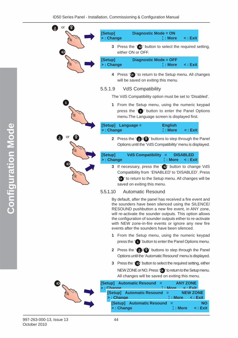
ID50 Series Panel - Installation, Commissioning & Configuration ManualC
on
fig
ura
tio
n M
od
e
44997-263-000-13, Issue 13October 2010
[Setup] Automatic Resound = ANY ZONE> : Change : More < : Exit
3 Press the ‘ 6 ’ button to select the required setting,
either ON or OFF.
4 Press ‘ 4 ’ to return to the Setup menu. All changes
will be saved on exiting this menu.
5.5.1.9 VdS Compatibility
The VdS Compatibility option must be set to ‘Disabled’.
1 From the Setup menu, using the numeric keypad
press the ‘ 1 ’ button to enter the Panel Options
menu.The Language screen is displayed first.
2 Press the ‘ 2 / 8 ’ buttons to step through the Panel
Options until the ‘VdS Compatibility’ menu is displayed.
3 If necessary, press the ‘ 6 ’ button to change VdS
Compatibility from ‘ENABLED’ to ‘DISABLED’. Press
‘ 4 ’ to return to the Setup menu. All changes will be
saved on exiting this menu.
5.5.1.10 Automatic Resound
By default, after the panel has received a fire event andthe sounders have been silenced using the SILENCE/RESOUND pushbutton a new fire event, in ANY zone,will re-activate the sounder outputs. This option allowsthe configuration of sounder outputs either to re-activatewith NEW zone-in-fire events or ignore any new fireevents after the sounders have been silenced.
1 From the Setup menu, using the numeric keypad
press the ‘ 1 ’ button to enter the Panel Options menu.
2 Press the ‘ 2 / 8 ’ buttons to step through the Panel
Options until the ‘Automatic Resound’ menu is displayed.
3 Press the ‘ 6 ’ button to select the required setting, either
NEW ZONE or NO. Press ‘ 4 ’ to return to the Setup menu.
All changes will be saved on exiting this menu.
1
or 82
6
[Setup] Language = English> : Change : More < : Exit
[Setup] VdS Compatibility = DISABLED> : Change : More < : Exit
6
or 82
[Setup] Diagnostic Mode = ON> : Change : More < : Exit
[Setup] Diagnostic Mode = OFF> : Change : More < : Exit
[Setup] Automatic Resound = NEW ZONE> : Change : More < : Exit
[Setup] Automatic Resound = NO> : Change : More < : Exit
6
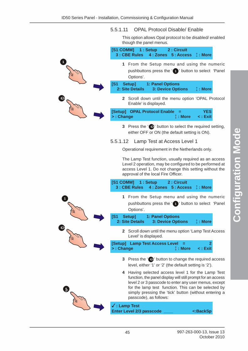
ID50 Series Panel - Installation, Commissioning & Configuration Manual
Co
nfi
gu
rati
on
Mo
de
45 997-263-000-13, Issue 13October 2010
5.5.1.11 OPAL Protocol Disable/ Enable
This option allows Opal protocol to be disabled/ enabledthough the panel menus.
1 From the Setup menu and using the numeric
pushbuttons press the ‘ 1 ’ button to select ‘Panel
Options’.
2 Scroll down until the menu option ‘OPAL ProtocolEnable’ is displayed.
3 Press the ‘ 6 ’ button to select the required setting,
either OFF or ON (the default setting is ON).
5.5.1.12 Lamp Test at Access Level 1
Operational requirement in the Netherlands only.
The Lamp Test function, usually required as an accessLevel 2 operation, may be configured to be performed ataccess Level 1. Do not change this setting without theapproval of the local Fire Officer.
1 From the Setup menu and using the numeric
pushbuttons press the ‘ 1 ’ button to select ‘Panel
Options’.
2 Scroll down until the menu option ‘Lamp Test AccessLevel’ is displayed.
3 Press the ‘ 6 ’ button to change the required access
level, either ‘1’ or ‘2’ (the default setting is ‘2’).
4 Having selected access level 1 for the Lamp Testfunction, the panel display will still prompt for an accesslevel 2 or 3 passcode to enter any user menus, exceptfor the lamp test function. This can be selected bysimply pressing the ‘tick’ button (without entering apasscode), as follows:
[S1 COMM] 1 : Setup 2 : Circuit3 : CBE Rules 4 : Zones 5 : Access : More
[S1 Setup] 1: Panel Options2: Site Details 3: Device Options : More
[Setup] Lamp Test Access Level = 2> : Change : More < : Exit
: Lamp TestEnter Level 2/3 passcode ____ <:BackSp
[S1 Setup] 1: Panel Options2: Site Details 3: Device Options : More
[Setup] OPAL Protocol Enable = YES> : Change : More < : Exit
1
6
5
1
6
[S1 COMM] 1 : Setup 2 : Circuit3 : CBE Rules 4 : Zones 5 : Access : More
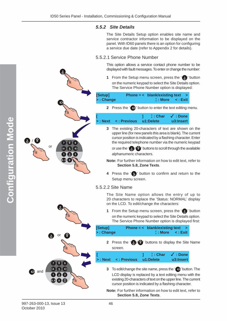
ID50 Series Panel - Installation, Commissioning & Configuration ManualC
on
fig
ura
tio
n M
od
e
46997-263-000-13, Issue 13October 2010
5.5.2 Site Details
The Site Details Setup option enables site name andservice contractor information to be displayed on thepanel. With ID60 panels there is an option for configuringa service due date (refer to Appendix 2 for details).
5.5.2.1 Service Phone Number
This option allows a service contact phone number to bedisplayed with fault messages. To enter or change the number:
1 From the Setup menu screen, press the ‘ 2 ’ button
on the numeric keypad to select the Site Details option.The Service Phone Number option is displayed:
2 Press the ‘ 6 ’ button to enter the text editing menu.
3 The existing 20-characters of text are shown on theupper line (for new panels this area is blank). The currentcursor position is indicated by a flashing character. Enterthe required telephone number via the numeric keypad
or use the ‘ 2 / 8 ’ buttons to scroll through the available
alphanumeric characters.
Note: For further information on how to edit text, refer toSection 5.8, Zone Texts.
4 Press the ‘ 5 ’ button to confirm and return to the
Setup menu screen.
5.5.2.2 Site Name
The Site Name option allows the entry of up to20 characters to replace the ‘Status: NORMAL’ displayon the LCD. To edit/change the characters:
1 From the Setup menu screen, press the ‘ 2 ’ button
on the numeric keypad to select the Site Details option.The Service Phone Number option is displayed first:
2 Press the ‘ 2 / 8 ’ buttons to display the Site Name
screen.
3 To edit/change the site name, press the ‘ 6 ’ button. The
LCD display is replaced by a text editing menu with theexisting 20-characters of text on the upper line. The currentcursor position is indicated by a flashing character.
Note: For further information on how to edit text, refer toSection 5.8, Zone Texts.
2
6
[Setup] Phone = < blank/existing text >> : Change : More < : Exit
or 8
2
2
[ ] : Char : Done> : Next < : Previous u1:Delete u3:Insert
[Setup] Phone = < blank/existing text >> : Change : More < : Exit
/ 82
or
6 and
[ ] : Char : Done> : Next < : Previous u1:Delete u3:Insert
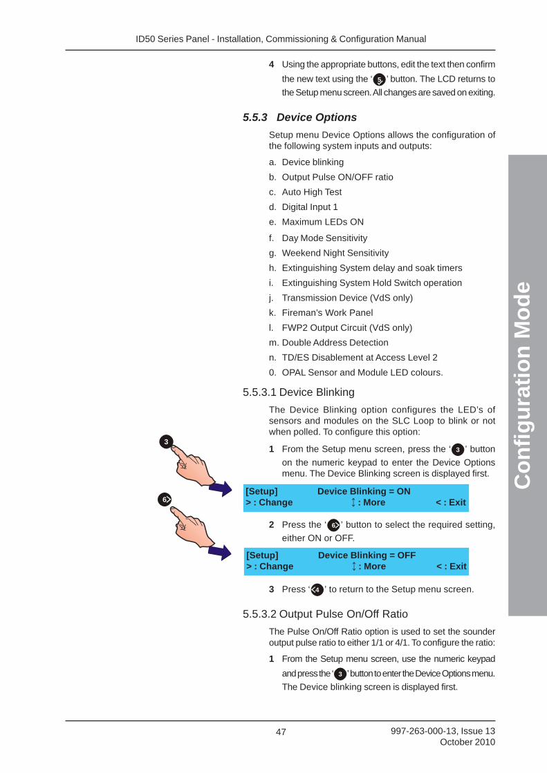
ID50 Series Panel - Installation, Commissioning & Configuration Manual
Co
nfi
gu
rati
on
Mo
de
47 997-263-000-13, Issue 13October 2010
4 Using the appropriate buttons, edit the text then confirm
the new text using the ‘ 5 ’ button. The LCD returns to
the Setup menu screen. All changes are saved on exiting.
5.5.3 Device Options
Setup menu Device Options allows the configuration ofthe following system inputs and outputs:
a. Device blinking
b. Output Pulse ON/OFF ratio
c. Auto High Test
d. Digital Input 1
e. Maximum LEDs ON
f. Day Mode Sensitivity
g. Weekend Night Sensitivity
h. Extinguishing System delay and soak timers
i. Extinguishing System Hold Switch operation
j. Transmission Device (VdS only)
k. Fireman’s Work Panel
l. FWP2 Output Circuit (VdS only)
m. Double Address Detection
n. TD/ES Disablement at Access Level 2
0. OPAL Sensor and Module LED colours.
5.5.3.1 Device Blinking
The Device Blinking option configures the LED’s ofsensors and modules on the SLC Loop to blink or notwhen polled. To configure this option:
1 From the Setup menu screen, press the ‘ 3 ’ button
on the numeric keypad to enter the Device Optionsmenu. The Device Blinking screen is displayed first.
2 Press the ‘ 6 ’ button to select the required setting,
either ON or OFF.
3 Press ‘ 4 ’ to return to the Setup menu screen.
5.5.3.2 Output Pulse On/Off Ratio
The Pulse On/Off Ratio option is used to set the sounderoutput pulse ratio to either 1/1 or 4/1. To configure the ratio:
1 From the Setup menu screen, use the numeric keypad
and press the ‘ 3 ’ button to enter the Device Options menu.
The Device blinking screen is displayed first.
3
[Setup] Device Blinking = ON> : Change : More < : Exit6
[Setup] Device Blinking = OFF> : Change : More < : Exit
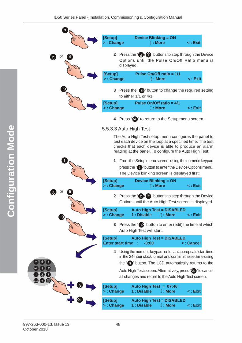
ID50 Series Panel - Installation, Commissioning & Configuration ManualC
on
fig
ura
tio
n M
od
e
48997-263-000-13, Issue 13October 2010
2 Press the ‘ 2 / 8 ’ buttons to step through the Device
Options until the Pulse On/Off Ratio menu isdisplayed.
3 Press the ‘ 6 ’ button to change the required setting
to either 1/1 or 4/1.
4 Press ‘ 4 ’ to return to the Setup menu screen.
5.5.3.3 Auto High Test
The Auto High Test setup menu configures the panel totest each device on the loop at a specified time. The testchecks that each device is able to produce an alarmreading at the panel. To configure the Auto High Test:
1 From the Setup menu screen, using the numeric keypad
press the ‘ 3 ’ button to enter the Device Options menu.
The Device blinking screen is displayed first:
2 Press the ‘ 2 / 8 ’ buttons to step through the Device
Options until the Auto High Test screen is displayed.
3 Press the ‘ 6 ’ button to enter (edit) the time at which
Auto High Test will start.
4 Using the numeric keypad, enter an appropriate start timein the 24-hour clock format and confirm the set time using
the ‘ 5 ’ button. The LCD automatically returns to the
Auto High Test screen. Alternatively, press ‘ 4 ’ to cancel
all changes and return to the Auto High Test screen.
6
[Setup] Pulse On/Off ratio = 4/1> : Change : More < : Exit
or 82
6
5
4
[Setup] Auto High Test = DISABLEDEnter start time : -0:00 < : Cancel
[Setup] Auto High Test = DISABLED> : Change 1 : Disable : More < : Exit
[Setup] Auto High Test = 07:46> : Change 1 : Disable : More < : Exit
[Setup] Auto High Test = DISABLED> : Change 1 : Disable : More < : Exit
3
[Setup] Device Blinking = ON> : Change : More < : Exit
or 82
[Setup] Pulse On/Off ratio = 1/1> : Change : More < : Exit
3
[Setup] Device Blinking = ON> : Change : More < : Exit
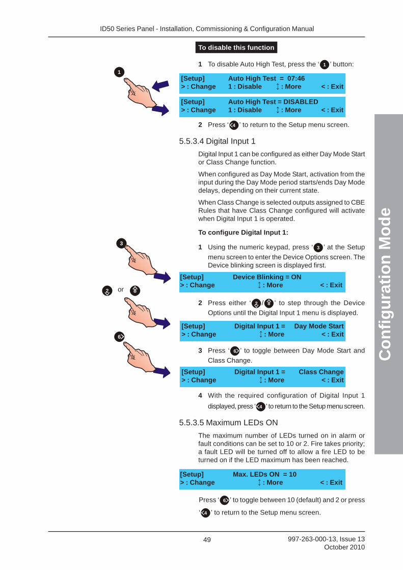
ID50 Series Panel - Installation, Commissioning & Configuration Manual
Co
nfi
gu
rati
on
Mo
de
49 997-263-000-13, Issue 13October 2010
[Setup] Auto High Test = DISABLED> : Change 1 : Disable : More < : Exit
[Setup] Auto High Test = 07:46> : Change 1 : Disable : More < : Exit
1
To disable this function
1 To disable Auto High Test, press the ‘ 1 ’ button:
2 Press ‘ 4 ’ to return to the Setup menu screen.
5.5.3.4 Digital Input 1
Digital Input 1 can be configured as either Day Mode Startor Class Change function.
When configured as Day Mode Start, activation from theinput during the Day Mode period starts/ends Day Modedelays, depending on their current state.
When Class Change is selected outputs assigned to CBERules that have Class Change configured will activatewhen Digital Input 1 is operated.
To configure Digital Input 1:
1 Using the numeric keypad, press ‘ 3 ’ at the Setup
menu screen to enter the Device Options screen. TheDevice blinking screen is displayed first.
2 Press either ‘ 2 / 8 ’ to step through the Device
Options until the Digital Input 1 menu is displayed.
3 Press ‘ 6 ’ to toggle between Day Mode Start and
Class Change.
4 With the required configuration of Digital Input 1
displayed, press ‘ 4 ’ to return to the Setup menu screen.
5.5.3.5 Maximum LEDs ON
The maximum number of LEDs turned on in alarm orfault conditions can be set to 10 or 2. Fire takes priority;a fault LED will be turned off to allow a fire LED to beturned on if the LED maximum has been reached.
[Setup] Digital Input 1 = Day Mode Start> : Change : More < : Exit
[Setup] Digital Input 1 = Class Change> : Change : More < : Exit
[Setup] Device Blinking = ON> : Change : More < : Exit
3
or 82
6
[Setup] Max. LEDs ON = 10> : Change : More < : Exit
Press ‘ 6 ’ to toggle between 10 (default) and 2 or press
‘ 4 ’ to return to the Setup menu screen.
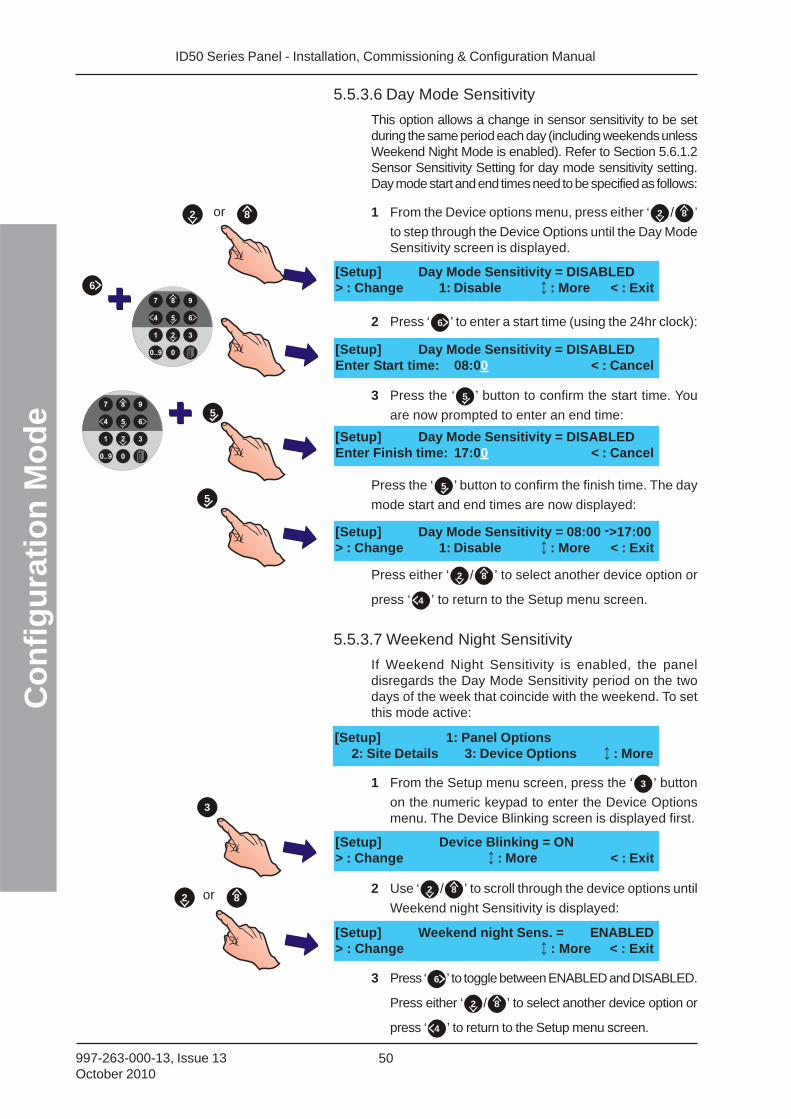
ID50 Series Panel - Installation, Commissioning & Configuration ManualC
on
fig
ura
tio
n M
od
e
50997-263-000-13, Issue 13October 2010
5.5.3.6 Day Mode Sensitivity
This option allows a change in sensor sensitivity to be setduring the same period each day (including weekends unlessWeekend Night Mode is enabled). Refer to Section 5.6.1.2Sensor Sensitivity Setting for day mode sensitivity setting.Day mode start and end times need to be specified as follows:
1 From the Device options menu, press either ‘ 2 / 8 ’
to step through the Device Options until the Day ModeSensitivity screen is displayed.
2 Press ‘ 6 ’ to enter a start time (using the 24hr clock):
3 Press the ‘ 5 ’ button to confirm the start time. You
are now prompted to enter an end time:
Press the ‘ 5 ’ button to confirm the finish time. The day
mode start and end times are now displayed:
Press either ‘ 2 / 8 ’ to select another device option or
press ‘ 4 ’ to return to the Setup menu screen.
5.5.3.7 Weekend Night Sensitivity
If Weekend Night Sensitivity is enabled, the paneldisregards the Day Mode Sensitivity period on the twodays of the week that coincide with the weekend. To setthis mode active:
1 From the Setup menu screen, press the ‘ 3 ’ button
on the numeric keypad to enter the Device Optionsmenu. The Device Blinking screen is displayed first.
2 Use ‘ 2 / 8 ’ to scroll through the device options until
Weekend night Sensitivity is displayed:
3 Press ‘ 6 ’ to toggle between ENABLED and DISABLED.
Press either ‘ 2 / 8 ’ to select another device option or
press ‘ 4 ’ to return to the Setup menu screen.
[Setup] Day Mode Sensitivity = DISABLEDEnter Finish time: 17:00 < : Cancel
[Setup] Day Mode Sensitivity = DISABLEDEnter Start time: 08:00 < : Cancel
[Setup] Day Mode Sensitivity = DISABLED> : Change 1: Disable : More < : Exit
[Setup] Day Mode Sensitivity = 08:00 ->17:00> : Change 1: Disable : More < : Exit
[Setup] Weekend night Sens. = ENABLED> : Change : More < : Exit
[Setup] 1: Panel Options2: Site Details 3: Device Options : More
[Setup] Device Blinking = ON> : Change : More < : Exit
or 82
5
6
5
3
or 82
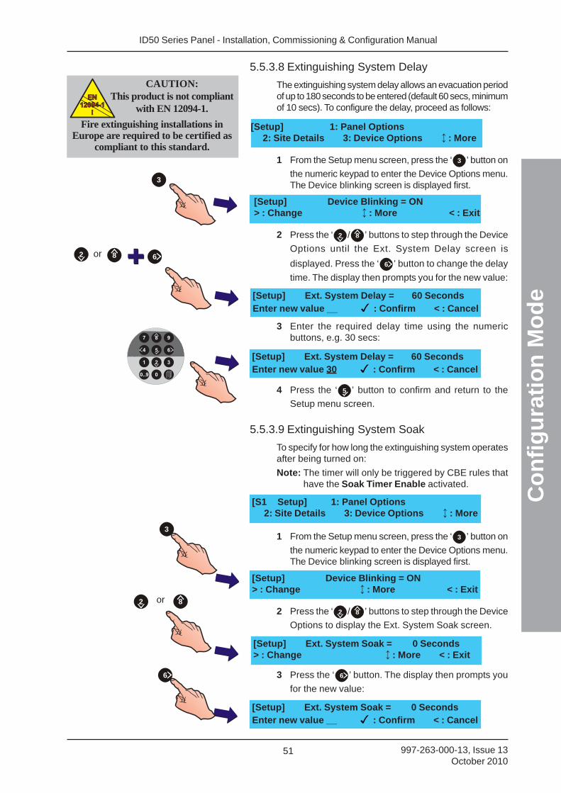
ID50 Series Panel - Installation, Commissioning & Configuration Manual
Co
nfi
gu
rati
on
Mo
de
51 997-263-000-13, Issue 13October 2010
[Setup] Ext. System Soak = 0 Seconds> : Change : More < : Exit
3
or 82
6
[Setup] Device Blinking = ON> : Change : More < : Exit
5.5.3.8 Extinguishing System Delay
The extinguishing system delay allows an evacuation periodof up to 180 seconds to be entered (default 60 secs, minimumof 10 secs). To configure the delay, proceed as follows:
1 From the Setup menu screen, press the ‘ 3 ’ button on
the numeric keypad to enter the Device Options menu.The Device blinking screen is displayed first.
2 Press the ‘ 2 / 8 ’ buttons to step through the Device
Options until the Ext. System Delay screen is
displayed. Press the ‘ 6 ’ button to change the delay
time. The display then prompts you for the new value:
3 Enter the required delay time using the numericbuttons, e.g. 30 secs:
4 Press the ‘ 5 ’ button to confirm and return to the
Setup menu screen.
5.5.3.9 Extinguishing System Soak
To specify for how long the extinguishing system operatesafter being turned on:
Note: The timer will only be triggered by CBE rules thathave the Soak Timer Enable activated.
1 From the Setup menu screen, press the ‘ 3 ’ button on
the numeric keypad to enter the Device Options menu.The Device blinking screen is displayed first.
2 Press the ‘ 2 / 8 ’ buttons to step through the Device
Options to display the Ext. System Soak screen.
3 Press the ‘ 6 ’ button. The display then prompts you
for the new value:
[Setup] Ext. System Soak = 0 SecondsEnter new value __ : Confirm < : Cancel
[Setup] Ext. System Delay = 60 SecondsEnter new value 30 : Confirm < : Cancel
6or 82
[Setup] Ext. System Delay = 60 SecondsEnter new value __ : Confirm < : Cancel
[Setup] 1: Panel Options2: Site Details 3: Device Options : More
[S1 Setup] 1: Panel Options2: Site Details 3: Device Options : More
3
CAUTION:This product is not compliant
with EN 12094-1.EN
12094-1
!
EN
12094-1
!
Fire extinguishing installations inEurope are required to be certified as
compliant to this standard.
[Setup] Device Blinking = ON> : Change : More < : Exit
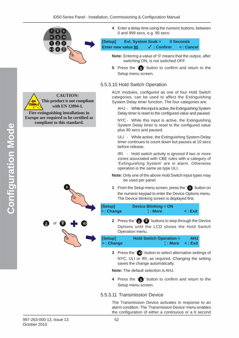
ID50 Series Panel - Installation, Commissioning & Configuration ManualC
on
fig
ura
tio
n M
od
e
52997-263-000-13, Issue 13October 2010
4 Enter a delay time using the numeric buttons, between0 and 999 secs, e.g. 90 secs:
Note: Entering a value of ‘0’ means that the output, afterswitching ON, is not switched OFF.
5 Press the ‘ 5 ’ button to confirm and return to the
Setup menu screen.
5.5.3.10 Hold Switch Operation
AUX modules, configured as one of four Hold Switchcategories, can be used to affect the ExtinguishingSystem Delay timer function. The four categories are:
AHJ - While this input is active, the Extinguishing SystemDelay timer is reset to the configured value and paused.
NYC - While this input is active, the ExtinguishingSystem Delay timer is reset to the configured valueplus 90 secs and paused.
ULI - While active, the Extinguishing System Delaytimer continues to count down but pauses at 10 secsbefore release.
IRI - Hold switch activity is ignored if two or morezones associated with CBE rules with a category of‘Extinguishing System’ are in alarm. Otherwiseoperation is the same as type ULI.
Note: Only one of the above Hold Switch input types maybe used per panel.
1 From the Setup menu screen, press the ‘ 3 ’ button on
the numeric keypad to enter the Device Options menu.The Device blinking screen is displayed first.
2 Press the ‘ 2 / 8 ’ buttons to step through the Device
Options until the LCD shows the Hold SwitchOperation menu.
3 Press the ‘ 6 ’ button to select alternative settings of
NYC, ULI or IRI, as required. Changing the settingsaves the change automatically.
Note: The default selection is AHJ.
4 Press the ‘ 5 ’ button to confirm and return to the
Setup menu screen.
5.5.3.11 Transmission Device
The Transmission Device activates in response to analarm condition. The ‘Transmission Device’ menu enablesthe configuration of either a continuous or a 6 second
3
[Setup] Ext. System Soak = 0 SecondsEnter new value 90 : Confirm < : Cancel
[Setup] Hold Switch Operation = AHJ> : Change : More < : Exit
[Setup] Device Blinking = ON> : Change : More < : Exit
or 82 6
CAUTION:This product is not compliant
with EN 12094-1.EN
12094-1
!
EN
12094-1
!
Fire extinguishing installations inEurope are required to be certified as
compliant to this standard.
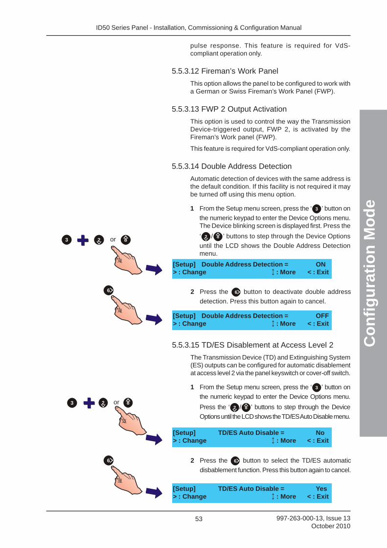
ID50 Series Panel - Installation, Commissioning & Configuration Manual
Co
nfi
gu
rati
on
Mo
de
53 997-263-000-13, Issue 13October 2010
pulse response. This feature is required for VdS-compliant operation only.
5.5.3.12 Fireman’s Work Panel
This option allows the panel to be configured to work witha German or Swiss Fireman’s Work Panel (FWP).
5.5.3.13 FWP 2 Output Activation
This option is used to control the way the TransmissionDevice-triggered output, FWP 2, is activated by theFireman’s Work panel (FWP).
This feature is required for VdS-compliant operation only.
5.5.3.14 Double Address Detection
Automatic detection of devices with the same address isthe default condition. If this facility is not required it maybe turned off using this menu option.
1 From the Setup menu screen, press the ‘ 3 ’ button on
the numeric keypad to enter the Device Options menu.The Device blinking screen is displayed first. Press the
‘ 2 / 8 ’ buttons to step through the Device Options
until the LCD shows the Double Address Detectionmenu.
[Setup] Double Address Detection = ON> : Change : More < : Exit
2 Press the 6 button to deactivate double address
detection. Press this button again to cancel.
[Setup] Double Address Detection = OFF> : Change : More < : Exit
6
or 82
5.5.3.15 TD/ES Disablement at Access Level 2
The Transmission Device (TD) and Extinguishing System(ES) outputs can be configured for automatic disablementat access level 2 via the panel keyswitch or cover-off switch.
1 From the Setup menu screen, press the ‘ 3 ’ button on
the numeric keypad to enter the Device Options menu.
Press the ‘ 2 / 8 ’ buttons to step through the Device
Options until the LCD shows the TD/ES Auto Disable menu.
[Setup] TD/ES Auto Disable = No> : Change : More < : Exit
3
3
6
[Setup] TD/ES Auto Disable = Yes> : Change : More < : Exit
2 Press the 6 button to select the TD/ES automatic
disbablement function. Press this button again to cancel.
or 82
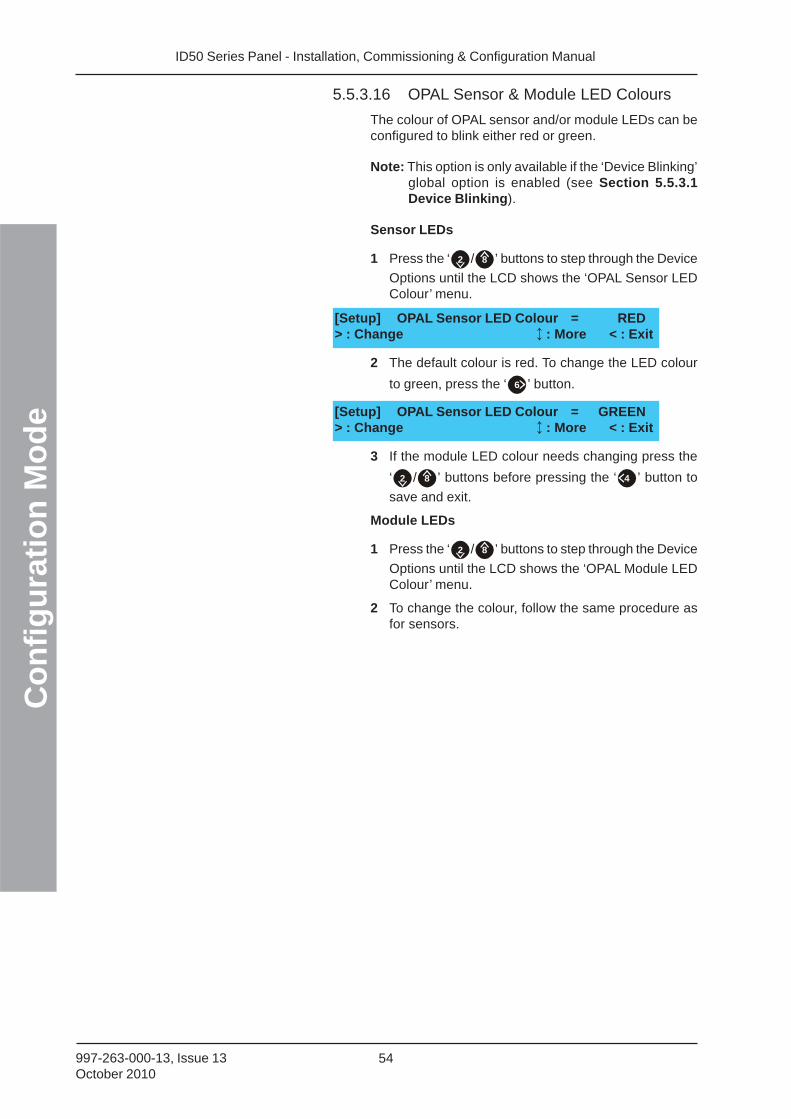
ID50 Series Panel - Installation, Commissioning & Configuration ManualC
on
fig
ura
tio
n M
od
e
54997-263-000-13, Issue 13October 2010
5.5.3.16 OPAL Sensor & Module LED Colours
The colour of OPAL sensor and/or module LEDs can beconfigured to blink either red or green.
Note: This option is only available if the ‘Device Blinking’global option is enabled (see Section 5.5.3.1Device Blinking).
Sensor LEDs
1 Press the ‘ 2 / 8 ’ buttons to step through the Device
Options until the LCD shows the ‘OPAL Sensor LEDColour’ menu.
2 The default colour is red. To change the LED colour
to green, press the ‘ 6 ’ button.
3 If the module LED colour needs changing press the
‘ 2 / 8 ’ buttons before pressing the ‘ 4 ’ button to
save and exit.
Module LEDs
1 Press the ‘ 2 / 8 ’ buttons to step through the Device
Options until the LCD shows the ‘OPAL Module LEDColour’ menu.
2 To change the colour, follow the same procedure asfor sensors.
[Setup] OPAL Sensor LED Colour = RED> : Change : More < : Exit
[Setup] OPAL Sensor LED Colour = GREEN> : Change : More < : Exit
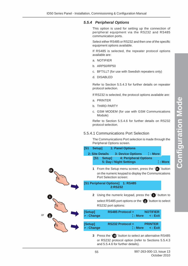
ID50 Series Panel - Installation, Commissioning & Configuration Manual
Co
nfi
gu
rati
on
Mo
de
55 997-263-000-13, Issue 13October 2010
5.5.4 Peripheral Options
This option is used for setting up the connection ofperipheral equipment via the RS232 and RS485communication ports.
Select either RS485 or RS232 and then one of the specificequipment options available.
If RS485 is selected, the repeater protocol optionsavailable are:
a. NOTIFIER
b. ARP50/RP50
c. BFT/LLT (for use with Swedish repeaters only)
d. DISABLED
Refer to Section 5.5.4.3 for further details on repeaterprotocol selection.
If RS232 is selected, the protocol options available are:
a. PRINTER
b. THIRD PARTY
c. GSM MODEM (for use with GSM CommunicationsModule)
Refer to Section 5.5.4.6 for further details on RS232protocol selection.
5.5.4.1 Communications Port Selection
The Communications Port selection is made through thePeripheral Options screen.
1 From the Setup menu screen, press the ‘ 4 ’ button
on the numeric keypad to display the CommunicationsPort Selection screen:
2 Using the numeric keypad, press the ‘ 1 ’ button to
select RS485 port options or the ‘ 2 ’ button to select
RS232 port options:
3 Press the ‘ 6 ’ button to select an alternative RS485
or RS232 protocol option (refer to Sections 5.5.4.3and 5.5.4.6 for further details).
4
or
2
1
2
[S1 Peripheral Options] 1: RS4852:RS232
[S1 Setup] 4: Peripheral Options5: Day / Night Settings : More
[S1 Setup] 1: Panel Options
2: Site Details 3: Device Options : More
[Setup] RS485 Protocol = NOTIFIER> : Change : More < : Exit
[Setup] RS232 Protocol = PRINTER> : Change : More < : Exit
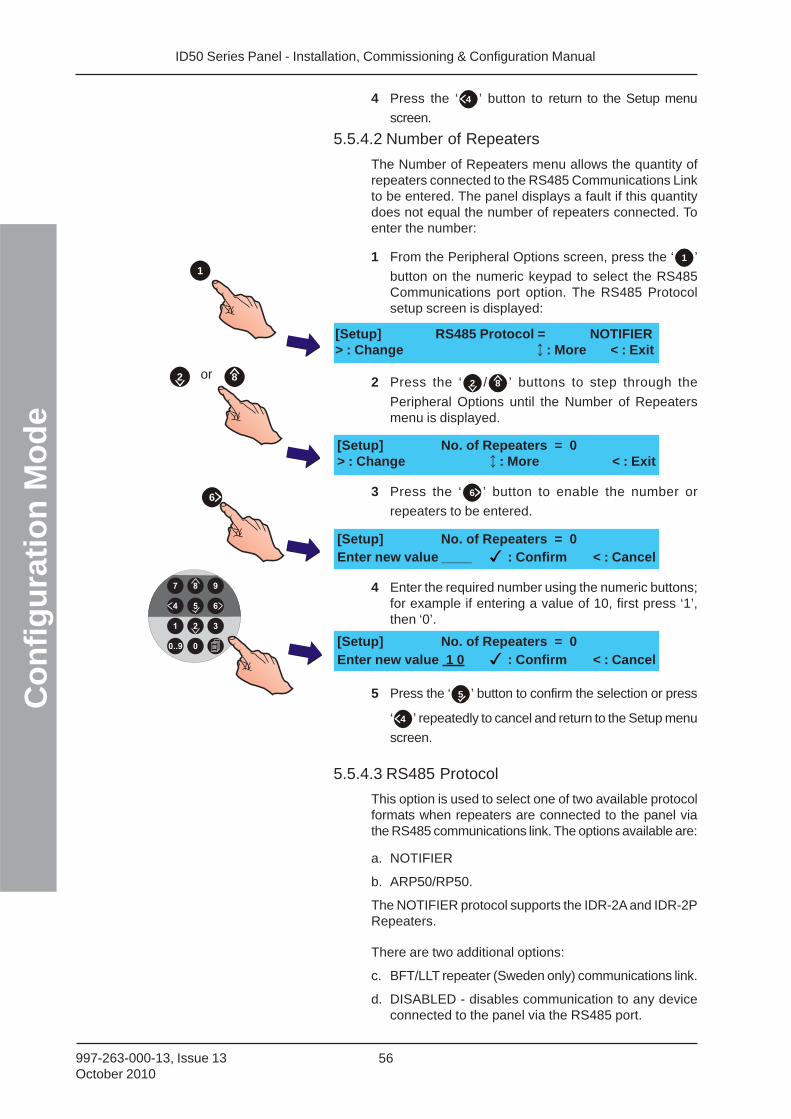
ID50 Series Panel - Installation, Commissioning & Configuration ManualC
on
fig
ura
tio
n M
od
e
56997-263-000-13, Issue 13October 2010
4 Press the ‘ 4 ’ button to return to the Setup menu
screen.
5.5.4.2 Number of Repeaters
The Number of Repeaters menu allows the quantity ofrepeaters connected to the RS485 Communications Linkto be entered. The panel displays a fault if this quantitydoes not equal the number of repeaters connected. Toenter the number:
1 From the Peripheral Options screen, press the ‘ 1 ’
button on the numeric keypad to select the RS485Communications port option. The RS485 Protocolsetup screen is displayed:
2 Press the ‘ 2 / 8 ’ buttons to step through the
Peripheral Options until the Number of Repeatersmenu is displayed.
3 Press the ‘ 6 ’ button to enable the number or
repeaters to be entered.
4 Enter the required number using the numeric buttons;for example if entering a value of 10, first press ‘1’,then ‘0’.
5 Press the ‘ 5 ’ button to confirm the selection or press
‘ 4 ’ repeatedly to cancel and return to the Setup menu
screen.
5.5.4.3 RS485 Protocol
This option is used to select one of two available protocolformats when repeaters are connected to the panel viathe RS485 communications link. The options available are:
a. NOTIFIER
b. ARP50/RP50.
The NOTIFIER protocol supports the IDR-2A and IDR-2PRepeaters.
There are two additional options:
c. BFT/LLT repeater (Sweden only) communications link.
d. DISABLED - disables communication to any deviceconnected to the panel via the RS485 port.
1
or 82
6
[Setup] RS485 Protocol = NOTIFIER> : Change : More < : Exit
[Setup] No. of Repeaters = 0Enter new value 1 0 : Confirm < : Cancel
[Setup] No. of Repeaters = 0Enter new value ____ : Confirm < : Cancel
[Setup] No. of Repeaters = 0> : Change : More < : Exit
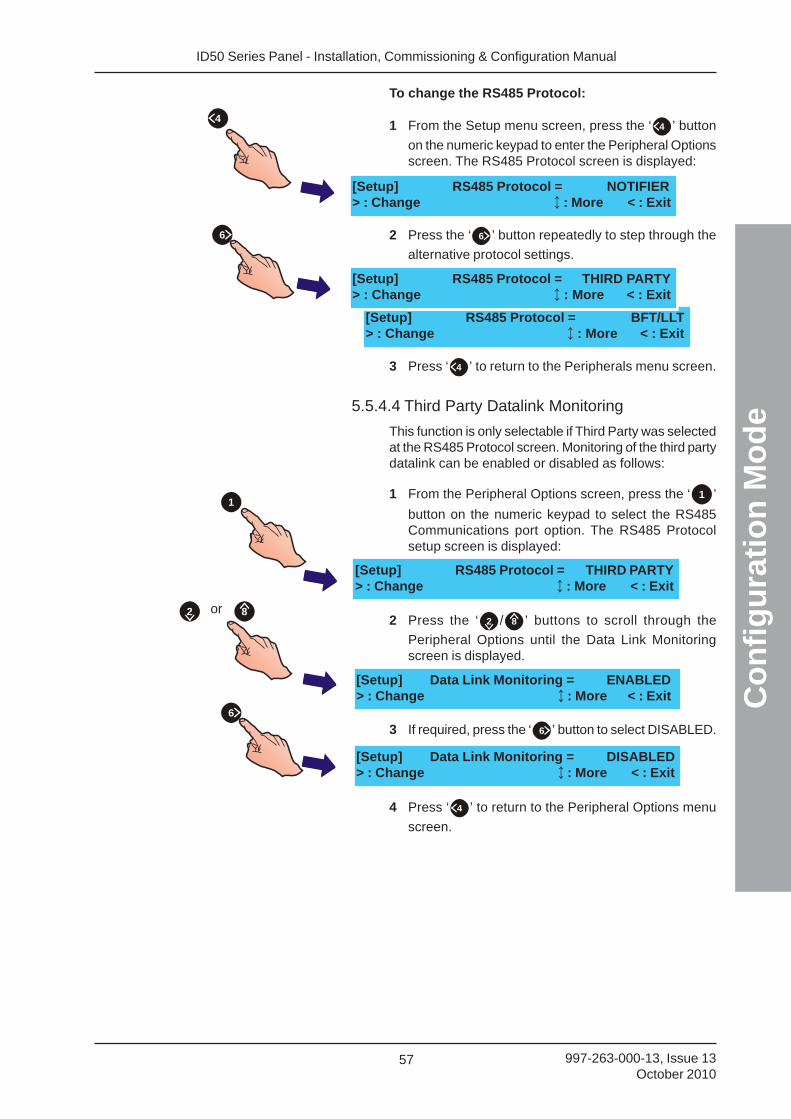
ID50 Series Panel - Installation, Commissioning & Configuration Manual
Co
nfi
gu
rati
on
Mo
de
57 997-263-000-13, Issue 13October 2010
To change the RS485 Protocol:
1 From the Setup menu screen, press the ‘ 4 ’ button
on the numeric keypad to enter the Peripheral Optionsscreen. The RS485 Protocol screen is displayed:
2 Press the ‘ 6 ’ button repeatedly to step through the
alternative protocol settings.
3 Press ‘ 4 ’ to return to the Peripherals menu screen.
5.5.4.4 Third Party Datalink Monitoring
This function is only selectable if Third Party was selectedat the RS485 Protocol screen. Monitoring of the third partydatalink can be enabled or disabled as follows:
1 From the Peripheral Options screen, press the ‘ 1 ’
button on the numeric keypad to select the RS485Communications port option. The RS485 Protocolsetup screen is displayed:
2 Press the ‘ 2 / 8 ’ buttons to scroll through the
Peripheral Options until the Data Link Monitoringscreen is displayed.
3 If required, press the ‘ 6 ’ button to select DISABLED.
4 Press ‘ 4 ’ to return to the Peripheral Options menu
screen.
[Setup] RS485 Protocol = NOTIFIER> : Change : More < : Exit
[Setup] RS485 Protocol = BFT/LLT> : Change : More < : Exit
[Setup] RS485 Protocol = THIRD PARTY> : Change : More < : Exit
4
6
[Setup] Data Link Monitoring = DISABLED> : Change : More < : Exit
[Setup] Data Link Monitoring = ENABLED> : Change : More < : Exit
[Setup] RS485 Protocol = THIRD PARTY> : Change : More < : Exit
or 82
6
1
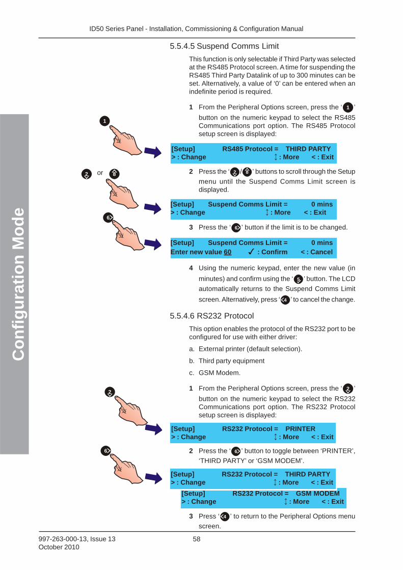
ID50 Series Panel - Installation, Commissioning & Configuration ManualC
on
fig
ura
tio
n M
od
e
58997-263-000-13, Issue 13October 2010
5.5.4.5 Suspend Comms Limit
This function is only selectable if Third Party was selectedat the RS485 Protocol screen. A time for suspending theRS485 Third Party Datalink of up to 300 minutes can beset. Alternatively, a value of ‘0’ can be entered when anindefinite period is required.
1 From the Peripheral Options screen, press the ‘ 1 ’
button on the numeric keypad to select the RS485Communications port option. The RS485 Protocolsetup screen is displayed:
2 Press the ‘ 2 / 8 ’ buttons to scroll through the Setup
menu until the Suspend Comms Limit screen isdisplayed.
3 Press the ‘ 6 ’ button if the limit is to be changed.
4 Using the numeric keypad, enter the new value (in
minutes) and confirm using the ‘ 5 ’ button. The LCD
automatically returns to the Suspend Comms Limit
screen. Alternatively, press ‘ 4 ’ to cancel the change.
5.5.4.6 RS232 Protocol
This option enables the protocol of the RS232 port to beconfigured for use with either driver:
a. External printer (default selection).
b. Third party equipment
c. GSM Modem.
1 From the Peripheral Options screen, press the ‘ 2 ’
button on the numeric keypad to select the RS232Communications port option. The RS232 Protocolsetup screen is displayed:
2 Press the ‘ 6 ’ button to toggle between ‘PRINTER’,
‘THIRD PARTY’ or ‘GSM MODEM’.
3 Press ‘ 4 ’ to return to the Peripheral Options menu
screen.
[Setup] RS485 Protocol = THIRD PARTY> : Change : More < : Exit
[Setup] Suspend Comms Limit = 0 mins> : Change : More < : Exit
or 82
[Setup] Suspend Comms Limit = 0 minsEnter new value 60 : Confirm < : Cancel
6
1
[Setup] RS232 Protocol = PRINTER> : Change : More < : Exit
[Setup] RS232 Protocol = GSM MODEM> : Change : More < : Exit
[Setup] RS232 Protocol = THIRD PARTY> : Change : More < : Exit
6
2
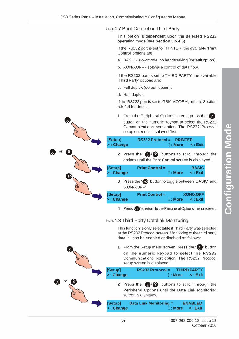
ID50 Series Panel - Installation, Commissioning & Configuration Manual
Co
nfi
gu
rati
on
Mo
de
59 997-263-000-13, Issue 13October 2010
5.5.4.7 Print Control or Third Party
This option is dependent upon the selected RS232operating mode (see Section 5.5.4.6).
If the RS232 port is set to PRINTER, the available ‘PrintControl’ options are:
a. BASIC - slow mode, no handshaking (default option).
b. XON/XOFF - software control of data flow.
If the RS232 port is set to THIRD PARTY, the available‘Third Party’ options are:
c. Full duplex (default option).
d. Half duplex.
If the RS232 port is set to GSM MODEM, refer to Section5.5.4.9 for details.
1 From the Peripheral Options screen, press the ‘ 2 ’
button on the numeric keypad to select the RS232Communications port option. The RS232 Protocolsetup screen is displayed first:
2 Press the ‘ 2 / 8 ’ buttons to scroll through the
options until the Print Control screen is displayed.
3 Press the ‘ 6 ’ button to toggle between ‘BASIC’ and
‘XON/XOFF’
4 Press ‘ 4 ’ to return to the Peripheral Options menu screen.
5.5.4.8 Third Party Datalink Monitoring
This function is only selectable if Third Party was selectedat the RS232 Protocol screen. Monitoring of the third partydatalink can be enabled or disabled as follows:
1 From the Setup menu screen, press the ‘ 2 ’ button
on the numeric keypad to select the RS232Communications port option. The RS232 Protocolsetup screen is displayed:
2 Press the ‘ 2 / 8 ’ buttons to scroll through the
Peripheral Options until the Data Link Monitoringscreen is displayed.
or 82
[Setup] Data Link Monitoring = ENABLED> : Change : More < : Exit
[Setup] RS232 Protocol = THIRD PARTY> : Change : More < : Exit
2
[Setup] RS232 Protocol = PRINTER> : Change : More < : Exit
[Setup] Print Control = XON/XOFF> : Change : More < : Exit
[Setup] Print Control = BASIC> : Change : More < : Exit
or 82
6
2
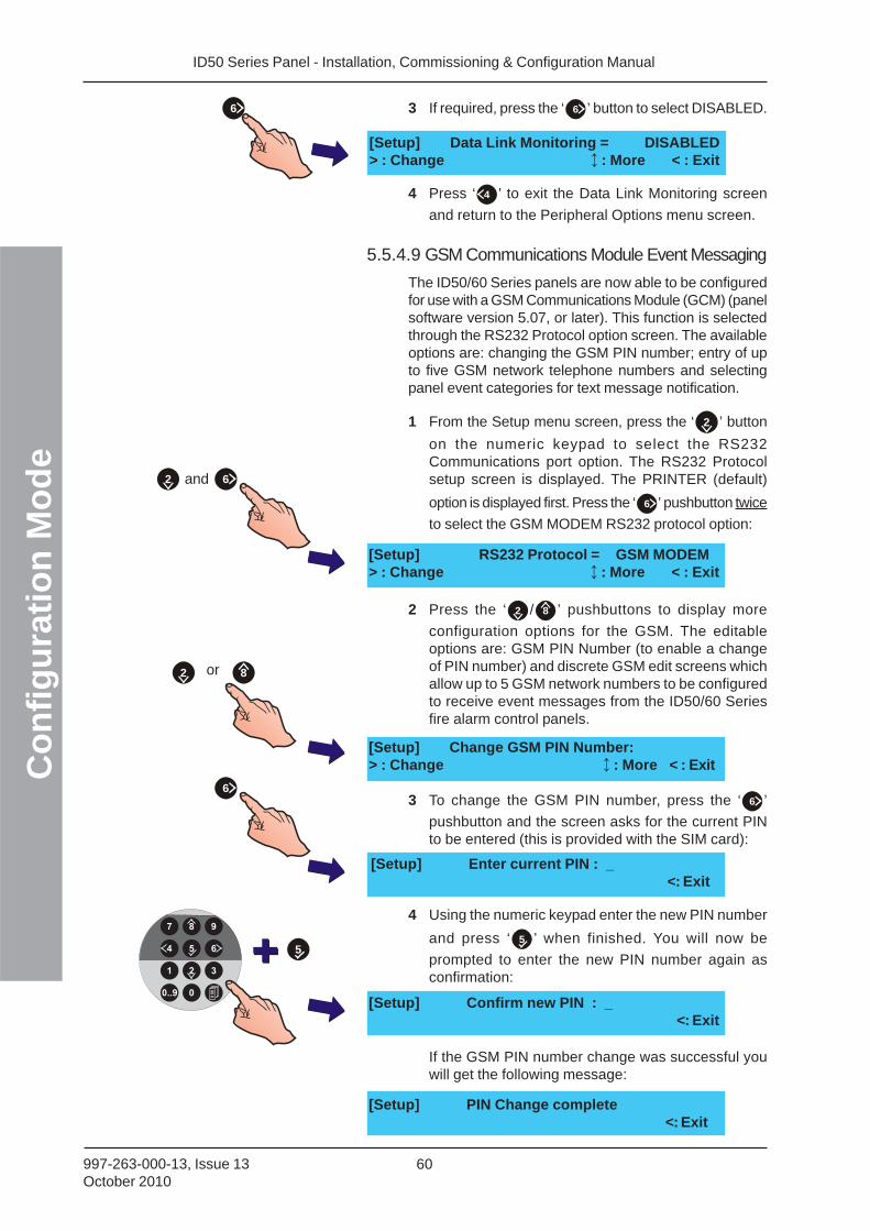
ID50 Series Panel - Installation, Commissioning & Configuration ManualC
on
fig
ura
tio
n M
od
e
60997-263-000-13, Issue 13October 2010
3 If required, press the ‘ 6 ’ button to select DISABLED.
4 Press ‘ 4 ’ to exit the Data Link Monitoring screen
and return to the Peripheral Options menu screen.
5.5.4.9 GSM Communications Module Event Messaging
The ID50/60 Series panels are now able to be configuredfor use with a GSM Communications Module (GCM) (panelsoftware version 5.07, or later). This function is selectedthrough the RS232 Protocol option screen. The availableoptions are: changing the GSM PIN number; entry of upto five GSM network telephone numbers and selectingpanel event categories for text message notification.
1 From the Setup menu screen, press the ‘ 2 ’ button
on the numeric keypad to select the RS232Communications port option. The RS232 Protocolsetup screen is displayed. The PRINTER (default)
option is displayed first. Press the ‘ 6 ’ pushbutton twice
to select the GSM MODEM RS232 protocol option:
2 Press the ‘ 2 / 8 ’ pushbuttons to display more
configuration options for the GSM. The editableoptions are: GSM PIN Number (to enable a changeof PIN number) and discrete GSM edit screens whichallow up to 5 GSM network numbers to be configuredto receive event messages from the ID50/60 Seriesfire alarm control panels.
3 To change the GSM PIN number, press the ‘ 6 ’
pushbutton and the screen asks for the current PINto be entered (this is provided with the SIM card):
4 Using the numeric keypad enter the new PIN number
and press ‘ 5 ’ when finished. You will now be
prompted to enter the new PIN number again asconfirmation:
If the GSM PIN number change was successful youwill get the following message:
6
[Setup] Data Link Monitoring = DISABLED> : Change : More < : Exit
[Setup] RS232 Protocol = GSM MODEM> : Change : More < : Exit
[Setup] Change GSM PIN Number:> : Change : More < : Exit
[Setup] Enter current PIN : _<: Exit
[Setup] Confirm new PIN : _<: Exit
[Setup] PIN Change complete<: Exit
2 and 6
or 82
6
5
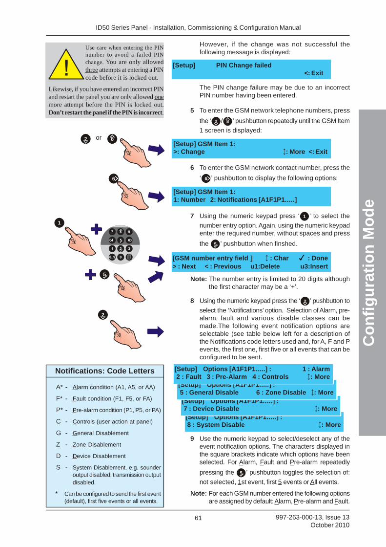
ID50 Series Panel - Installation, Commissioning & Configuration Manual
Co
nfi
gu
rati
on
Mo
de
61 997-263-000-13, Issue 13October 2010
However, if the change was not successful thefollowing message is displayed:
The PIN change failure may be due to an incorrectPIN number having been entered.
5 To enter the GSM network telephone numbers, press
the ‘ 2 / 8 ’ pushbutton repeatedly until the GSM Item
1 screen is displayed:
6 To enter the GSM network contact number, press the
‘ 6 ’ pushbutton to display the following options:
7 Using the numeric keypad press ‘ 1 ’ to select the
number entry option. Again, using the numeric keypadenter the required number, without spaces and press
the 5 ’ pushbutton when finshed.
Note: The number entry is limited to 20 digits althoughthe first character may be a ‘+’.
8 Using the numeric keypad press the ‘ 2 ’ pushbutton to
select the ‘Notifications’ option. Selection of Alarm, pre-alarm, fault and various disable classes can bemade.The following event notification options areselectable (see table below left for a description ofthe Notifications code letters used and, for A, F and Pevents, the first one, first five or all events that can beconfigured to be sent.
9 Use the numeric keypad to select/deselect any of theevent notification options. The characters displayed inthe square brackets indicate which options have beenselected. For Alarm, Fault and Pre-alarm repeatedly
pressing the 5 ’ pushbutton toggles the selection of:
not selected, 1st event, first 5 events or All events.
Note: For each GSM number entered the following optionsare assigned by default: Alarm, Pre-alarm and Fault.
[Setup] PIN Change failed<: Exit
[Setup] GSM Item 1:1: Number 2: Notifications [A1F1P1.....]
[GSM number entry field ] : Char : Done> : Next < : Previous u1:Delete u3:Insert
[Setup] GSM Item 1:>: Change : More <: Exit
or 82
6
1
5
[Setup] Options [A1F1P1.....] : 8 : System Disable : More
[Setup] Options [A1F1P1.....] : 7 : Device Disable : More
[Setup] Options [A1F1P1.....] : 5 : General Disable 6 : Zone Disable : More
[Setup] Options [A1F1P1.....] : 1 : Alarm 2 : Fault 3 : Pre-Alarm 4 : Controls : More
2
Notifications: Code Letters
A* - Alarm condition (A1, A5, or AA)
F* - Fault condition (F1, F5, or FA)
P* - Pre-alarm condition (P1, P5, or PA)
C - Controls (user action at panel)
G - General Disablement
Z - Zone Disablement
D - Device Disablement
S - System Disablement, e.g. sounderoutput disabled, transmission outputdisabled.
* Can be configured to send the first event(default), first five events or all events.
Use care when entering the PINnumber to avoid a failed PINchange. You are only allowedthree attempts at entering a PINcode before it is locked out.
Likewise, if you have entered an incorrect PINand restart the panel you are only allowed onemore attempt before the PIN is locked out.Don’t restart the panel if the PIN is incorrect.
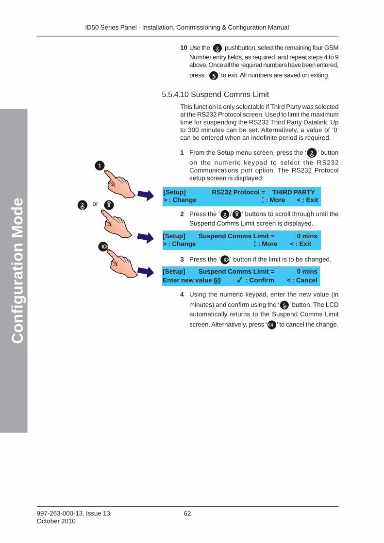
ID50 Series Panel - Installation, Commissioning & Configuration ManualC
on
fig
ura
tio
n M
od
e
62997-263-000-13, Issue 13October 2010
[Setup] RS232 Protocol = THIRD PARTY> : Change : More < : Exit
[Setup] Suspend Comms Limit = 0 mins> : Change : More < : Exit
or 82
[Setup] Suspend Comms Limit = 0 minsEnter new value 60 : Confirm < : Cancel
6
1
10 Use the ‘ 2 ’ pushbutton, select the remaining four GSM
Number entry fields, as required, and repeat steps 4 to 9above. Once all the required numbers have been entered,
press ‘ 5 ’ to exit. All numbers are saved on exiting.
5.5.4.10 Suspend Comms Limit
This function is only selectable if Third Party was selectedat the RS232 Protocol screen. Used to limit the maximumtime for suspending the RS232 Third Party Datalink. Upto 300 minutes can be set. Alternatively, a value of ‘0’can be entered when an indefinite period is required.
1 From the Setup menu screen, press the ‘ 2 ’ button
on the numeric keypad to select the RS232Communications port option. The RS232 Protocolsetup screen is displayed:
2 Press the ‘ 2 / 8 ’ buttons to scroll through until the
Suspend Comms Limit screen is displayed.
3 Press the ‘ 6 ’ button if the limit is to be changed.
4 Using the numeric keypad, enter the new value (in
minutes) and confirm using the ‘ 5 ’ button. The LCD
automatically returns to the Suspend Comms Limit
screen. Alternatively, press ‘ 4 ’ to cancel the change.
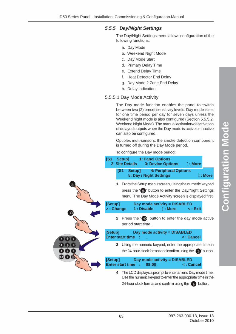
ID50 Series Panel - Installation, Commissioning & Configuration Manual
Co
nfi
gu
rati
on
Mo
de
63 997-263-000-13, Issue 13October 2010
5.5.5 Day/Night Settings
The Day/Night Settings menu allows configuration of thefollowing functions:
a. Day Mode
b. Weekend Night Mode
c. Day Mode Start
d. Primary Delay Time
e. Extend Delay Time
f. Heat Detector End Delay
g. Day Mode 2 Zone End Delay
h. Delay Indication.
5.5.5.1 Day Mode Activity
The Day mode function enables the panel to switchbetween two (2) preset sensitivity levels. Day mode is setfor one time period per day for seven days unless theWeekend night mode is also configured (Section 5.5.5.2,Weekend Night Mode). The manual activation/deactivationof delayed outputs when the Day mode is active or inactivecan also be configured.
Optiplex mult-sensors: the smoke detection componentis turned off during the Day Mode period.
To configure the Day mode period:
1 From the Setup menu screen, using the numeric keypad
press the ‘ 5 ’ button to enter the Day/Night Settings
menu. The Day Mode Activity screen is displayed first.
2 Press the ‘ 6 ’ button to enter the day mode active
period start time.
3 Using the numeric keypad, enter the appropriate time in
the 24-hour clock format and confirm using the ‘ 5 ’ button.
4 The LCD displays a prompt to enter an end Day mode time.Use the numeric keypad to enter the appropriate time in the
24-hour clock format and confirm using the ‘ 5 ’ button.
5
6
[S1 Setup] 4: Peripheral Options5: Day / Night Settings : More
[S1 Setup] 1: Panel Options2: Site Details 3: Device Options : More
[Setup] Day mode activity = DISABLED> : Change 1 : Disable : More < : Exit
[Setup] Day mode activity = DISABLEDEnter start time : _ < : Cancel
[Setup] Day mode activity = DISABLEDEnter start time : 08:00 < : Cancel
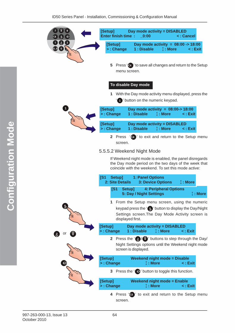
ID50 Series Panel - Installation, Commissioning & Configuration ManualC
on
fig
ura
tio
n M
od
e
64997-263-000-13, Issue 13October 2010
1 [Setup] Day mode activity = 08:00-> 18:00> : Change 1 : Disable : More < : Exit
[Setup] Day mode activity = DISABLED> : Change 1 : Disable : More < : Exit
[S1 Setup] 4: Peripheral Options5: Day / Night Settings : More
[S1 Setup] 1: Panel Options2: Site Details 3: Device Options : More
5 Press ‘ 4 ’ to save all changes and return to the Setup
menu screen.
To disable Day mode
1 With the Day mode activity menu displayed, press the
‘ 1 ’ button on the numeric keypad.
2 Press ‘ 4 ’ to exit and return to the Setup menu
screen.
5.5.5.2 Weekend Night Mode
If Weekend night mode is enabled, the panel disregardsthe Day mode period on the two days of the week thatcoincide with the weekend. To set this mode active:
1 From the Setup menu screen, using the numeric
keypad press the ‘ 5 ’ button to display the Day/Night
Settings screen.The Day Mode Activity screen isdisplayed first.
2 Press the ‘ 2 / 8 ’ buttons to step through the Day/
Night Settings options until the Weekend night modescreen is displayed.
3 Press the ‘ 6 ’ button to toggle this function.
4 Press ‘ 4 ’ to exit and return to the Setup menu
screen.
5
or 82
6
[Setup] Weekend night mode = Disable> : Change : More < : Exit
[Setup] Weekend night mode = Enable> : Change : More < : Exit
[Setup] Day mode activity = DISABLED> : Change 1 : Disable : More < : Exit
[Setup] Day mode activity = DISABLEDEnter finish time : _0:00 < : Cancel
[Setup] Day mode activity = 08:00 -> 18:00> : Change 1 : Disable : More < : Exit
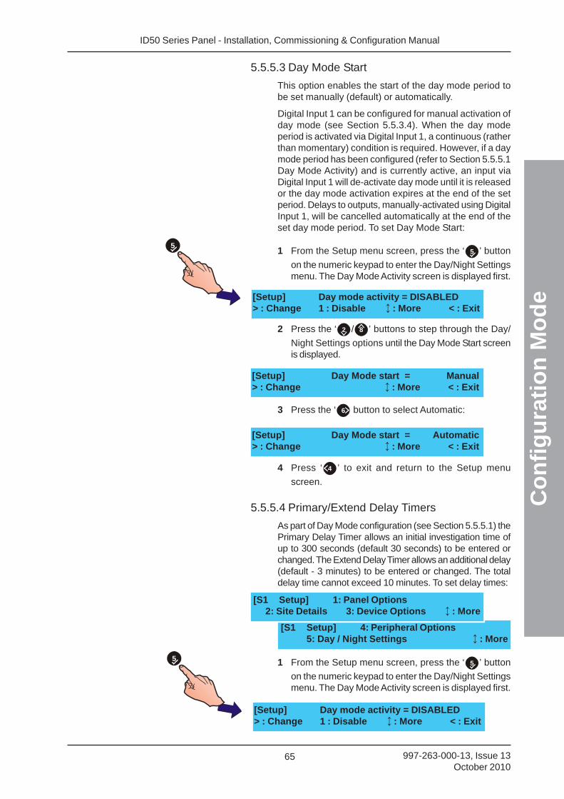
ID50 Series Panel - Installation, Commissioning & Configuration Manual
Co
nfi
gu
rati
on
Mo
de
65 997-263-000-13, Issue 13October 2010
5.5.5.3 Day Mode Start
This option enables the start of the day mode period tobe set manually (default) or automatically.
Digital Input 1 can be configured for manual activation ofday mode (see Section 5.5.3.4). When the day modeperiod is activated via Digital Input 1, a continuous (ratherthan momentary) condition is required. However, if a daymode period has been configured (refer to Section 5.5.5.1Day Mode Activity) and is currently active, an input viaDigital Input 1 will de-activate day mode until it is releasedor the day mode activation expires at the end of the setperiod. Delays to outputs, manually-activated using DigitalInput 1, will be cancelled automatically at the end of theset day mode period. To set Day Mode Start:
1 From the Setup menu screen, press the ‘ 5 ’ button
on the numeric keypad to enter the Day/Night Settingsmenu. The Day Mode Activity screen is displayed first.
2 Press the ‘ 2 / 8 ’ buttons to step through the Day/
Night Settings options until the Day Mode Start screenis displayed.
3 Press the ‘ 6 button to select Automatic:
4 Press ‘ 4 ’ to exit and return to the Setup menu
screen.
5.5.5.4 Primary/Extend Delay Timers
As part of Day Mode configuration (see Section 5.5.5.1) thePrimary Delay Timer allows an initial investigation time ofup to 300 seconds (default 30 seconds) to be entered orchanged. The Extend Delay Timer allows an additional delay(default - 3 minutes) to be entered or changed. The totaldelay time cannot exceed 10 minutes. To set delay times:
1 From the Setup menu screen, press the ‘ 5 ’ button
on the numeric keypad to enter the Day/Night Settingsmenu. The Day Mode Activity screen is displayed first.
[S1 Setup] 4: Peripheral Options5: Day / Night Settings : More
[S1 Setup] 1: Panel Options2: Site Details 3: Device Options : More
5
[Setup] Day mode activity = DISABLED> : Change 1 : Disable : More < : Exit
[Setup] Day Mode start = Manual> : Change : More < : Exit
[Setup] Day Mode start = Automatic> : Change : More < : Exit
5
[Setup] Day mode activity = DISABLED> : Change 1 : Disable : More < : Exit
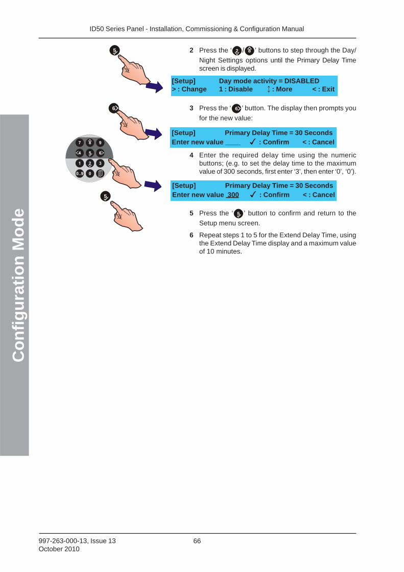
ID50 Series Panel - Installation, Commissioning & Configuration ManualC
on
fig
ura
tio
n M
od
e
66997-263-000-13, Issue 13October 2010
6
5
[Setup] Primary Delay Time = 30 SecondsEnter new value ____ : Confirm < : Cancel
[Setup] Primary Delay Time = 30 SecondsEnter new value 300 : Confirm < : Cancel
2 Press the ‘ 2 / 8 ’ buttons to step through the Day/
Night Settings options until the Primary Delay Timescreen is displayed.
3 Press the ‘ 6 ’ button. The display then prompts you
for the new value:
4 Enter the required delay time using the numericbuttons; (e.g. to set the delay time to the maximumvalue of 300 seconds, first enter ‘3’, then enter ‘0’, ‘0’).
5 Press the ‘ 5 ’ button to confirm and return to the
Setup menu screen.
6 Repeat steps 1 to 5 for the Extend Delay Time, usingthe Extend Delay Time display and a maximum valueof 10 minutes.
5
[Setup] Day mode activity = DISABLED> : Change 1 : Disable : More < : Exit

ID50 Series Panel - Installation, Commissioning & Configuration Manual
Co
nfi
gu
rati
on
Mo
de
67 997-263-000-13, Issue 13October 2010
5.5.5.5 Heat Det. End Delay
The Day Mode function, Delays to outputs, can becancelled when a heat sensor goes into alarm. To selectthe Heat Det. End Delay option:
1 From the Setup menu screen, press the ‘ 5 ’ button
on the numeric keypad to enter the Day/Night Settingsmenu. The Day mode activity screen is displayed first.
2 Press the ‘ 2 / 8 ’ buttons to step through the Day/
Night Settings options until the Heat Det. End Delayscreen is displayed.
3 Press the ‘ 6 ’ button to toggle this function.
4 Press ‘ 4 ’ to exit and return to the Setup menu
screen. The selection is saved on exiting.
5.5.5.6 Day Mode 2 Zone Ends Delay
The Day Mode function, Delays to outputs, can becancelled, through this Day/Night Settings option, by asecond zone going into alarm. This is an alternative to asecond device in the same zone going into alarm or theactivation of an MCP cancelling active delay timers.
To select the Day Mode 2 Zone Ends Delay option:
1 From the Setup menu screen, press the ‘ 5 ’ button
on the numeric keypad to enter the Day/Night Settingsmenu. The Day mode activity screen is displayed first.
2 Press the ‘ 2 / 8 ’ buttons to step through the Day/
Night Settings options until the Day Mode 2 Zone EndsDelay screen is displayed.
[S1 Setup] 4: Peripheral Options5: Day / Night Settings : More
[S1 Setup] 1: Panel Options2: Site Details 3: Device Options : More
[Setup] Heat Det. End Delay = No> : Change : More < : Exit
[Setup] Heat Det. End Delay = Yes> : Change : More < : Exit
6
or 82
[S1 Setup] 4: Peripheral Options5: Day / Night Settings : More
[S1 Setup] 1: Panel Options2: Site Details 3: Device Options : More
[Setup] Day Mode 2 Zone Ends Delay = No> : Change : More < : Exit
or 82
5
[Setup] Day mode activity = DISABLED> : Change 1 : Disable : More < : Exit
5
[Setup] Day mode activity = DISABLED> : Change 1 : Disable : More < : Exit
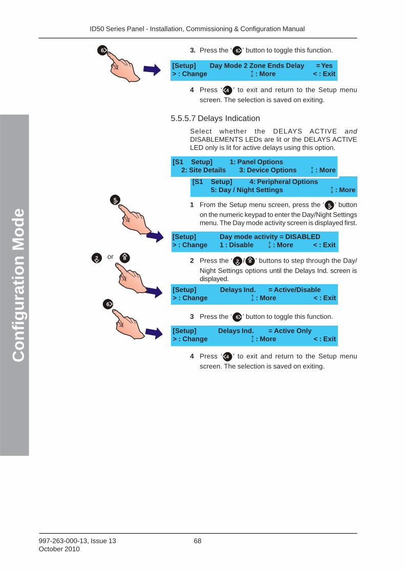
ID50 Series Panel - Installation, Commissioning & Configuration ManualC
on
fig
ura
tio
n M
od
e
68997-263-000-13, Issue 13October 2010
[Setup] Delays Ind. = Active/Disable> : Change : More < : Exit
[Setup] Delays Ind. = Active Only> : Change : More < : Exit
6
or 82
3. Press the ‘ 6 ’ button to toggle this function.
4 Press ‘ 4 ’ to exit and return to the Setup menu
screen. The selection is saved on exiting.
5.5.5.7 Delays Indication
Select whether the DELAYS ACTIVE andDISABLEMENTS LEDs are lit or the DELAYS ACTIVELED only is lit for active delays using this option.
1 From the Setup menu screen, press the ‘ 5 ’ button
on the numeric keypad to enter the Day/Night Settingsmenu. The Day mode activity screen is displayed first.
2 Press the ‘ 2 / 8 ’ buttons to step through the Day/
Night Settings options until the Delays Ind. screen isdisplayed.
3 Press the ‘ 6 ’ button to toggle this function.
4 Press ‘ 4 ’ to exit and return to the Setup menu
screen. The selection is saved on exiting.
[Setup] Day Mode 2 Zone Ends Delay = Yes> : Change : More < : Exit
6
[S1 Setup] 4: Peripheral Options5: Day / Night Settings : More
[S1 Setup] 1: Panel Options2: Site Details 3: Device Options : More
5
[Setup] Day mode activity = DISABLED> : Change 1 : Disable : More < : Exit
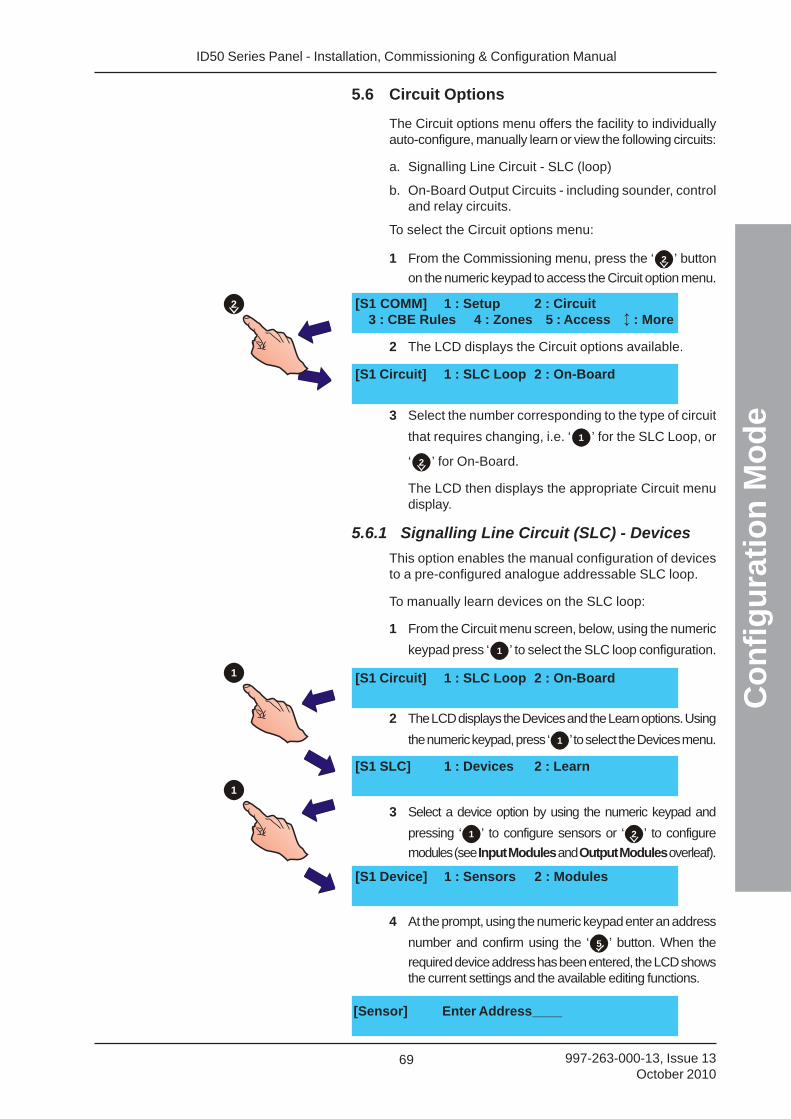
ID50 Series Panel - Installation, Commissioning & Configuration Manual
Co
nfi
gu
rati
on
Mo
de
69 997-263-000-13, Issue 13October 2010
[Sensor] Enter Address____
5.6 Circuit Options
The Circuit options menu offers the facility to individuallyauto-configure, manually learn or view the following circuits:
a. Signalling Line Circuit - SLC (loop)
b. On-Board Output Circuits - including sounder, controland relay circuits.
To select the Circuit options menu:
1 From the Commissioning menu, press the ‘ 2 ’ button
on the numeric keypad to access the Circuit option menu.
2 The LCD displays the Circuit options available.
3 Select the number corresponding to the type of circuit
that requires changing, i.e. ‘ 1 ’ for the SLC Loop, or
‘ 2 ’ for On-Board.
The LCD then displays the appropriate Circuit menudisplay.
5.6.1 Signalling Line Circuit (SLC) - Devices
This option enables the manual configuration of devicesto a pre-configured analogue addressable SLC loop.
To manually learn devices on the SLC loop:
1 From the Circuit menu screen, below, using the numeric
keypad press ‘ 1 ’ to select the SLC loop configuration.
2 The LCD displays the Devices and the Learn options. Using
the numeric keypad, press ‘ 1 ’ to select the Devices menu.
3 Select a device option by using the numeric keypad and
pressing ‘ 1 ’ to configure sensors or ‘ 2 ’ to configure
modules (see Input Modules and Output Modules overleaf).
4 At the prompt, using the numeric keypad enter an address
number and confirm using the ‘ 5 ’ button. When the
required device address has been entered, the LCD showsthe current settings and the available editing functions.
[S1 COMM] 1 : Setup 2 : Circuit3 : CBE Rules 4 : Zones 5 : Access : More
[S1 Circuit] 1 : SLC Loop 2 : On-Board
[S1 Circuit] 1 : SLC Loop 2 : On-Board
[S1 SLC] 1 : Devices 2 : Learn
[S1 Device] 1 : Sensors 2 : Modules
2
1
1
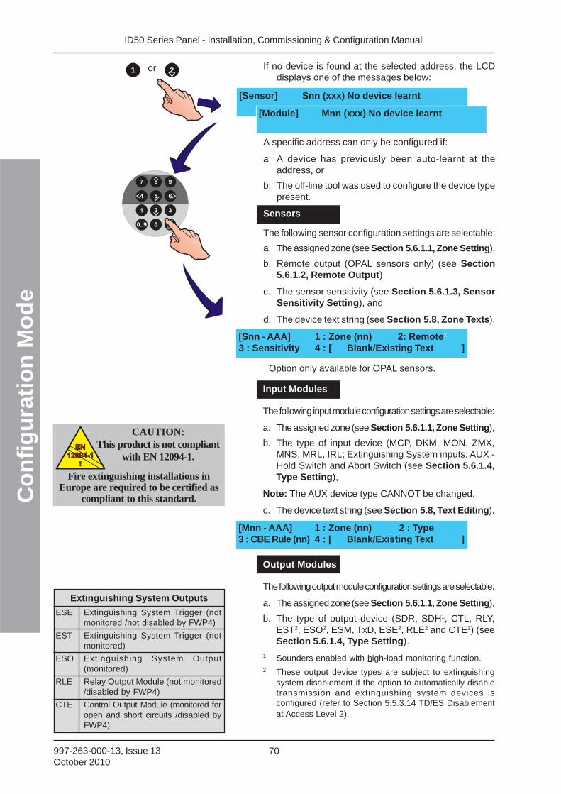
ID50 Series Panel - Installation, Commissioning & Configuration ManualC
on
fig
ura
tio
n M
od
e
70997-263-000-13, Issue 13October 2010
[Mnn - AAA] 1 : Zone (nn) 2 : Type3 : CBE Rule (nn) 4 : [ Blank/Existing Text ]
If no device is found at the selected address, the LCDdisplays one of the messages below:
A specific address can only be configured if:
a. A device has previously been auto-learnt at theaddress, or
b. The off-line tool was used to configure the device typepresent.
Sensors
The following sensor configuration settings are selectable:
a. The assigned zone (see Section 5.6.1.1, Zone Setting),
b. Remote output (OPAL sensors only) (see Section5.6.1.2, Remote Output)
c. The sensor sensitivity (see Section 5.6.1.3, SensorSensitivity Setting), and
d. The device text string (see Section 5.8, Zone Texts).
1 Option only available for OPAL sensors.
[Sensor] Snn (xxx) No device learnt
[Module] Mnn (xxx) No device learnt
or 21
CAUTION:This product is not compliant
with EN 12094-1.EN
12094-1
!
EN
12094-1
!
Fire extinguishing installations inEurope are required to be certified as
compliant to this standard.
ESE Extinguishing System Trigger (notmonitored /not disabled by FWP4)
EST Extinguishing System Trigger (notmonitored)
ESO Extinguishing System Output(monitored)
RLE Relay Output Module (not monitored/disabled by FWP4)
CTE Control Output Module (monitored foropen and short circuits /disabled byFWP4)
Extinguishing System Outputs
[Snn - AAA] 1 : Zone (nn) 2: Remote1
3 : Sensitivity 4 : [ Blank/Existing Text ]
Input Modules
The following input module configuration settings are selectable:
a. The assigned zone (see Section 5.6.1.1, Zone Setting),
b. The type of input device (MCP, DKM, MON, ZMX,MNS, MRL, IRL; Extinguishing System inputs: AUX -Hold Switch and Abort Switch (see Section 5.6.1.4,Type Setting),
Note: The AUX device type CANNOT be changed.
c. The device text string (see Section 5.8, Text Editing).
Output Modules
The following output module configuration settings are selectable:
a. The assigned zone (see Section 5.6.1.1, Zone Setting),
b. The type of output device (SDR, SDH1, CTL, RLY,EST2, ESO2, ESM, TxD, ESE2, RLE2 and CTE2) (seeSection 5.6.1.4, Type Setting).
1 Sounders enabled with high-load monitoring function.2 These output device types are subject to extinguishing
system disablement if the option to automatically disabletransmission and extinguishing system devices isconfigured (refer to Section 5.5.3.14 TD/ES Disablementat Access Level 2).
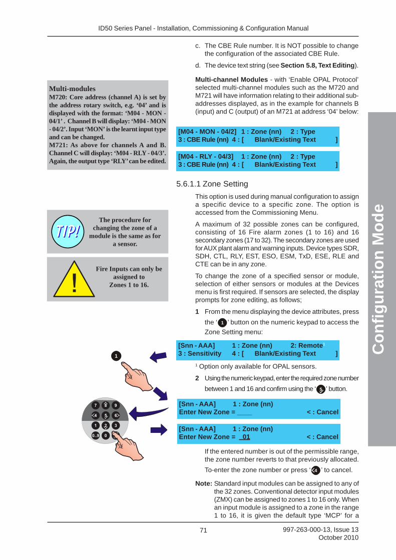
ID50 Series Panel - Installation, Commissioning & Configuration Manual
Co
nfi
gu
rati
on
Mo
de
71 997-263-000-13, Issue 13October 2010
[M04 - MON - 04/2] 1 : Zone (nn) 2 : Type3 : CBE Rule (nn) 4 : [ Blank/Existing Text ]
Multi-modulesM720: Core address (channel A) is set bythe address rotary switch, e.g. ‘04’ and isdisplayed with the format: ‘M04 - MON -04/1’ . Channel B will display: ‘M04 - MON- 04/2’. Input ‘MON’ is the learnt input typeand can be changed.M721: As above for channels A and B.Channel C will display: ‘M04 - RLY - 04/3’.Again, the output type ‘RLY’ can be edited.
[M04 - RLY - 04/3] 1 : Zone (nn) 2 : Type3 : CBE Rule (nn) 4 : [ Blank/Existing Text ]
5.6.1.1 Zone Setting
This option is used during manual configuration to assigna specific device to a specific zone. The option isaccessed from the Commissioning Menu.
A maximum of 32 possible zones can be configured,consisting of 16 Fire alarm zones (1 to 16) and 16secondary zones (17 to 32). The secondary zones are usedfor AUX plant alarm and warning inputs. Device types SDR,SDH, CTL, RLY, EST, ESO, ESM, TxD, ESE, RLE andCTE can be in any zone.
To change the zone of a specified sensor or module,selection of either sensors or modules at the Devicesmenu is first required. If sensors are selected, the displayprompts for zone editing, as follows;
1 From the menu displaying the device attributes, press
the ‘ 1 ’ button on the numeric keypad to access the
Zone Setting menu:
1 Option only available for OPAL sensors.
2 Using the numeric keypad, enter the required zone number
between 1 and 16 and confirm using the ‘ 5 ’ button.
If the entered number is out of the permissible range,the zone number reverts to that previously allocated.
To-enter the zone number or press ‘ 4 ’ to cancel.
Note: Standard input modules can be assigned to any ofthe 32 zones. Conventional detector input modules(ZMX) can be assigned to zones 1 to 16 only. Whenan input module is assigned to a zone in the range1 to 16, it is given the default type ‘MCP’ for a
Fire Inputs can only beassigned to
Zones 1 to 16.
The procedure forchanging the zone of a
module is the same as fora sensor.
[Snn - AAA] 1 : Zone (nn) 2: Remote1
3 : Sensitivity 4 : [ Blank/Existing Text ]
[Snn - AAA] 1 : Zone (nn)Enter New Zone = ____ < : Cancel
[Snn - AAA] 1 : Zone (nn)Enter New Zone = 01 < : Cancel
1
Multi-channel Modules - with ‘Enable OPAL Protocol’selected multi-channel modules such as the M720 andM721 will have information relating to their additional sub-addresses displayed, as in the example for channels B(input) and C (output) of an M721 at address ‘04’ below:
c. The CBE Rule number. It is NOT possible to changethe configuration of the associated CBE Rule.
d. The device text string (see Section 5.8, Text Editing).
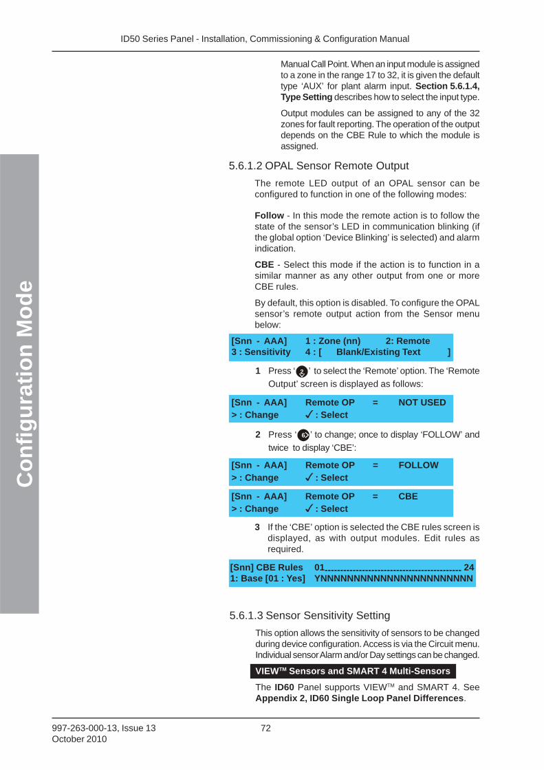
ID50 Series Panel - Installation, Commissioning & Configuration ManualC
on
fig
ura
tio
n M
od
e
72997-263-000-13, Issue 13October 2010
Manual Call Point. When an input module is assignedto a zone in the range 17 to 32, it is given the defaulttype ‘AUX’ for plant alarm input. Section 5.6.1.4,Type Setting describes how to select the input type.
Output modules can be assigned to any of the 32zones for fault reporting. The operation of the outputdepends on the CBE Rule to which the module isassigned.
5.6.1.2 OPAL Sensor Remote Output
The remote LED output of an OPAL sensor can beconfigured to function in one of the following modes:
Follow - In this mode the remote action is to follow thestate of the sensor’s LED in communication blinking (ifthe global option ‘Device Blinking’ is selected) and alarmindication.
CBE - Select this mode if the action is to function in asimilar manner as any other output from one or moreCBE rules.
By default, this option is disabled. To configure the OPALsensor’s remote output action from the Sensor menubelow:
[Snn - AAA] 1 : Zone (nn) 2: Remote3 : Sensitivity 4 : [ Blank/Existing Text ]
1 Press ‘ 2 ’ to select the ‘Remote’ option. The ‘Remote
Output’ screen is displayed as follows:
2 Press ‘ 6 ’ to change; once to display ‘FOLLOW’ and
twice to display ‘CBE’:
[Snn - AAA] Remote OP = NOT USED> : Change : Select
[Snn - AAA] Remote OP = FOLLOW> : Change : Select
[Snn - AAA] Remote OP = CBE> : Change : Select
3 If the ‘CBE’ option is selected the CBE rules screen isdisplayed, as with output modules. Edit rules asrequired.
[Snn] CBE Rules 01-------------------------------------------- 241: Base [01 : Yes] YNNNNNNNNNNNNNNNNNNNNNNN
5.6.1.3 Sensor Sensitivity Setting
This option allows the sensitivity of sensors to be changedduring device configuration. Access is via the Circuit menu.Individual sensor Alarm and/or Day settings can be changed.
VIEWTM Sensors and SMART 4 Multi-Sensors
The ID60 Panel supports VIEWTM and SMART 4. SeeAppendix 2, ID60 Single Loop Panel Differences.
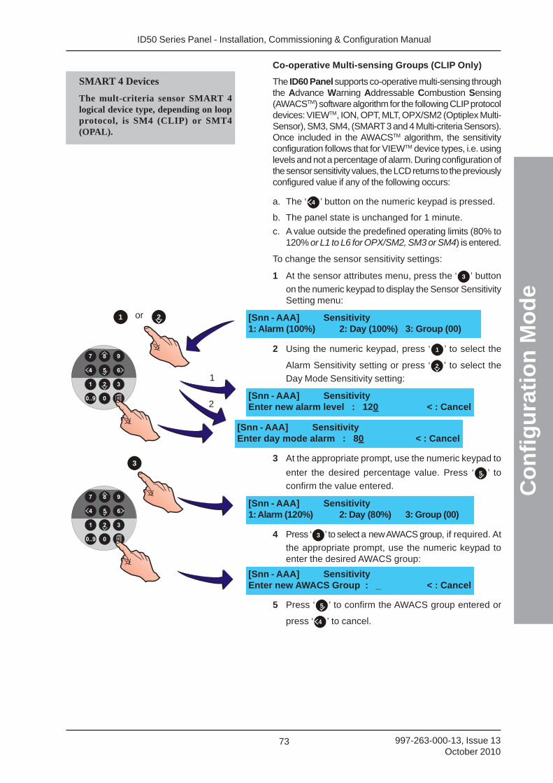
ID50 Series Panel - Installation, Commissioning & Configuration Manual
Co
nfi
gu
rati
on
Mo
de
73 997-263-000-13, Issue 13October 2010
Co-operative Multi-sensing Groups (CLIP Only)
The ID60 Panel supports co-operative multi-sensing throughthe Advance Warning Addressable Combustion Sensing(AWACSTM) software algorithm for the following CLIP protocoldevices: VIEWTM, ION, OPT, MLT, OPX/SM2 (Optiplex Multi-Sensor), SM3, SM4, (SMART 3 and 4 Multi-criteria Sensors).Once included in the AWACSTM algorithm, the sensitivityconfiguration follows that for VIEWTM device types, i.e. usinglevels and not a percentage of alarm. During configuration ofthe sensor sensitivity values, the LCD returns to the previouslyconfigured value if any of the following occurs:
a. The ‘ 4 ’ button on the numeric keypad is pressed.
b. The panel state is unchanged for 1 minute.
c. A value outside the predefined operating limits (80% to120% or L1 to L6 for OPX/SM2, SM3 or SM4) is entered.
To change the sensor sensitivity settings:
1 At the sensor attributes menu, press the ‘ 3 ’ button
on the numeric keypad to display the Sensor SensitivitySetting menu:
2 Using the numeric keypad, press ‘ 1 ’ to select the
Alarm Sensitivity setting or press ‘ 2 ’ to select the
Day Mode Sensitivity setting:
3 At the appropriate prompt, use the numeric keypad to
enter the desired percentage value. Press ‘ 5 ’ to
confirm the value entered.
4 Press ‘ 3 ’ to select a new AWACS group, if required. At
the appropriate prompt, use the numeric keypad toenter the desired AWACS group:
5 Press ‘ 5 ’ to confirm the AWACS group entered or
press ‘ 4 ’ to cancel.
[Snn - AAA] SensitivityEnter new alarm level : 120 < : Cancel
[Snn - AAA] Sensitivity1: Alarm (100%) 2: Day (100%) 3: Group (00)
[Snn - AAA] SensitivityEnter day mode alarm : 80 < : Cancel
[Snn - AAA] Sensitivity1: Alarm (120%) 2: Day (80%) 3: Group (00)
1
2
or 21
[Snn - AAA] SensitivityEnter new AWACS Group : _ < : Cancel
3
SMART 4 Devices
The mult-criteria sensor SMART 4logical device type, depending on loopprotocol, is SM4 (CLIP) or SMT4(OPAL).
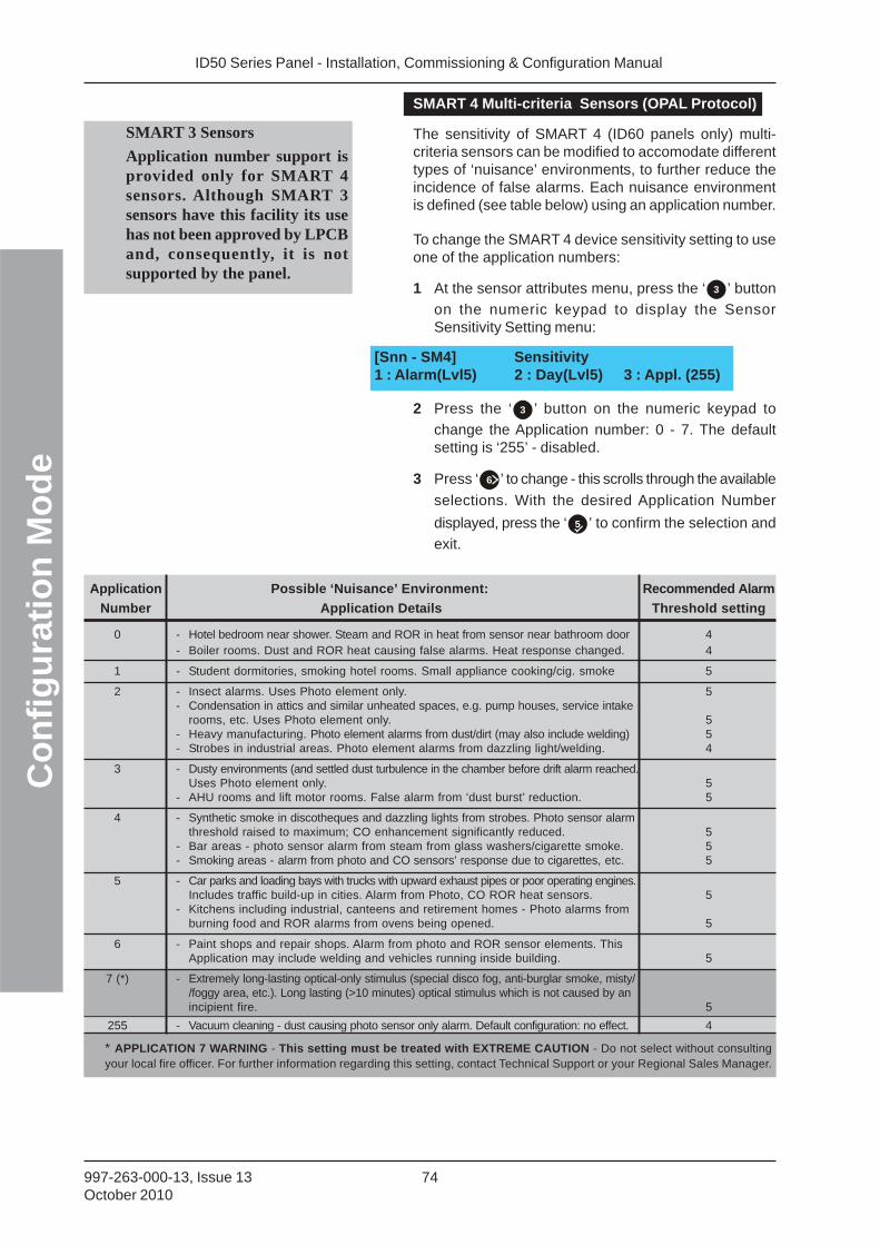
ID50 Series Panel - Installation, Commissioning & Configuration ManualC
on
fig
ura
tio
n M
od
e
74997-263-000-13, Issue 13October 2010
[Snn - SM4] Sensitivity1 : Alarm(Lvl5) 2 : Day(Lvl5) 3 : Appl. (255)
* APPLICATION 7 WARNING - This setting must be treated with EXTREME CAUTION - Do not select without consultingyour local fire officer. For further information regarding this setting, contact Technical Support or your Regional Sales Manager.
SMART 4 Multi-criteria Sensors (OPAL Protocol)
The sensitivity of SMART 4 (ID60 panels only) multi-criteria sensors can be modified to accomodate differenttypes of ‘nuisance’ environments, to further reduce theincidence of false alarms. Each nuisance environmentis defined (see table below) using an application number.
To change the SMART 4 device sensitivity setting to useone of the application numbers:
1 At the sensor attributes menu, press the ‘ 3 ’ button
on the numeric keypad to display the SensorSensitivity Setting menu:
2 Press the ‘ 3 ’ button on the numeric keypad to
change the Application number: 0 - 7. The defaultsetting is ‘255’ - disabled.
3 Press ‘ 6 ’ to change - this scrolls through the available
selections. With the desired Application Number
displayed, press the ‘ 5 ’ to confirm the selection and
exit.
SMART 3 Sensors
Application number support isprovided only for SMART 4sensors. Although SMART 3sensors have this facility its usehas not been approved by LPCBand, consequently, it is notsupported by the panel.
Application Possible ‘Nuisance’ Environment: Recommended Alarm
Number Application Details Threshold setting
0 - Hotel bedroom near shower. Steam and ROR in heat from sensor near bathroom door 4- Boiler rooms. Dust and ROR heat causing false alarms. Heat response changed. 4
1 - Student dormitories, smoking hotel rooms. Small appliance cooking/cig. smoke 5
2 - Insect alarms. Uses Photo element only. 5- Condensation in attics and similar unheated spaces, e.g. pump houses, service intake
rooms, etc. Uses Photo element only. 5- Heavy manufacturing. Photo element alarms from dust/dirt (may also include welding) 5- Strobes in industrial areas. Photo element alarms from dazzling light/welding. 4
3 - Dusty environments (and settled dust turbulence in the chamber before drift alarm reached.Uses Photo element only. 5
- AHU rooms and lift motor rooms. False alarm from ‘dust burst’ reduction. 5
4 - Synthetic smoke in discotheques and dazzling lights from strobes. Photo sensor alarmthreshold raised to maximum; CO enhancement significantly reduced. 5
- Bar areas - photo sensor alarm from steam from glass washers/cigarette smoke. 5- Smoking areas - alarm from photo and CO sensors’ response due to cigarettes, etc. 5
5 - Car parks and loading bays with trucks with upward exhaust pipes or poor operating engines.Includes traffic build-up in cities. Alarm from Photo, CO ROR heat sensors. 5
- Kitchens including industrial, canteens and retirement homes - Photo alarms fromburning food and ROR alarms from ovens being opened. 5
6 - Paint shops and repair shops. Alarm from photo and ROR sensor elements. ThisApplication may include welding and vehicles running inside building. 5
7 (*) - Extremely long-lasting optical-only stimulus (special disco fog, anti-burglar smoke, misty//foggy area, etc.). Long lasting (>10 minutes) optical stimulus which is not caused by anincipient fire. 5
255 - Vacuum cleaning - dust causing photo sensor only alarm. Default configuration: no effect. 4
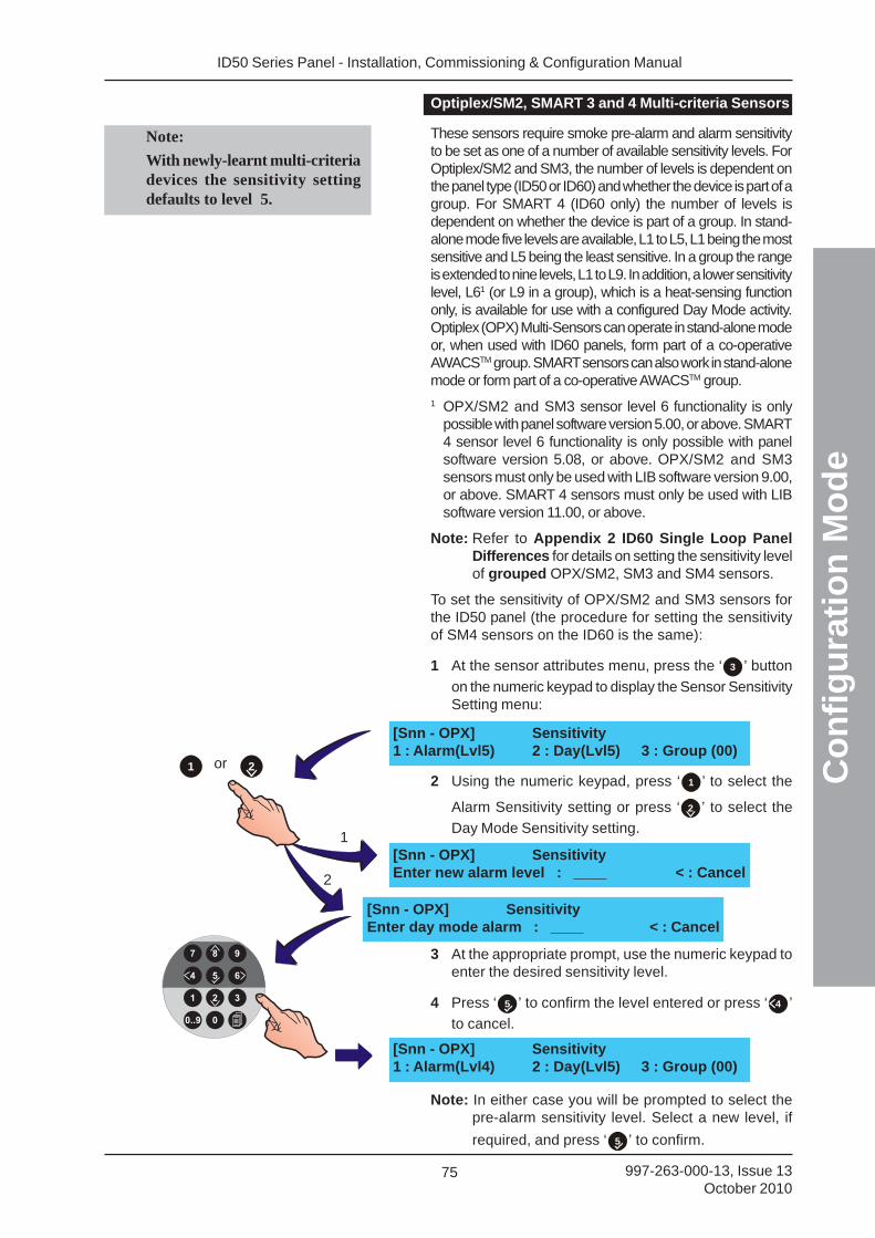
ID50 Series Panel - Installation, Commissioning & Configuration Manual
Co
nfi
gu
rati
on
Mo
de
75 997-263-000-13, Issue 13October 2010
[Snn - OPX] Sensitivity1 : Alarm(Lvl5) 2 : Day(Lvl5) 3 : Group (00)
or 21
1
2
[Snn - OPX] SensitivityEnter new alarm level : ____ < : Cancel
[Snn - OPX] SensitivityEnter day mode alarm : ____ < : Cancel
[Snn - OPX] Sensitivity1 : Alarm(Lvl4) 2 : Day(Lvl5) 3 : Group (00)
Note:
With newly-learnt multi-criteriadevices the sensitivity settingdefaults to level 5.
Optiplex/SM2, SMART 3 and 4 Multi-criteria Sensors
These sensors require smoke pre-alarm and alarm sensitivityto be set as one of a number of available sensitivity levels. ForOptiplex/SM2 and SM3, the number of levels is dependent onthe panel type (ID50 or ID60) and whether the device is part of agroup. For SMART 4 (ID60 only) the number of levels isdependent on whether the device is part of a group. In stand-alone mode five levels are available, L1 to L5, L1 being the mostsensitive and L5 being the least sensitive. In a group the rangeis extended to nine levels, L1 to L9. In addition, a lower sensitivitylevel, L61 (or L9 in a group), which is a heat-sensing functiononly, is available for use with a configured Day Mode activity.Optiplex (OPX) Multi-Sensors can operate in stand-alone modeor, when used with ID60 panels, form part of a co-operativeAWACSTM group. SMART sensors can also work in stand-alonemode or form part of a co-operative AWACSTM group.
1 OPX/SM2 and SM3 sensor level 6 functionality is onlypossible with panel software version 5.00, or above. SMART4 sensor level 6 functionality is only possible with panelsoftware version 5.08, or above. OPX/SM2 and SM3sensors must only be used with LIB software version 9.00,or above. SMART 4 sensors must only be used with LIBsoftware version 11.00, or above.
Note: Refer to Appendix 2 ID60 Single Loop PanelDifferences for details on setting the sensitivity levelof grouped OPX/SM2, SM3 and SM4 sensors.
To set the sensitivity of OPX/SM2 and SM3 sensors forthe ID50 panel (the procedure for setting the sensitivityof SM4 sensors on the ID60 is the same):
1 At the sensor attributes menu, press the ‘ 3 ’ button
on the numeric keypad to display the Sensor SensitivitySetting menu:
2 Using the numeric keypad, press ‘ 1 ’ to select the
Alarm Sensitivity setting or press ‘ 2 ’ to select the
Day Mode Sensitivity setting.
3 At the appropriate prompt, use the numeric keypad toenter the desired sensitivity level.
4 Press ‘ 5 ’ to confirm the level entered or press ‘ 4 ’
to cancel.
Note: In either case you will be prompted to select thepre-alarm sensitivity level. Select a new level, if
required, and press ‘ 5 ’ to confirm.
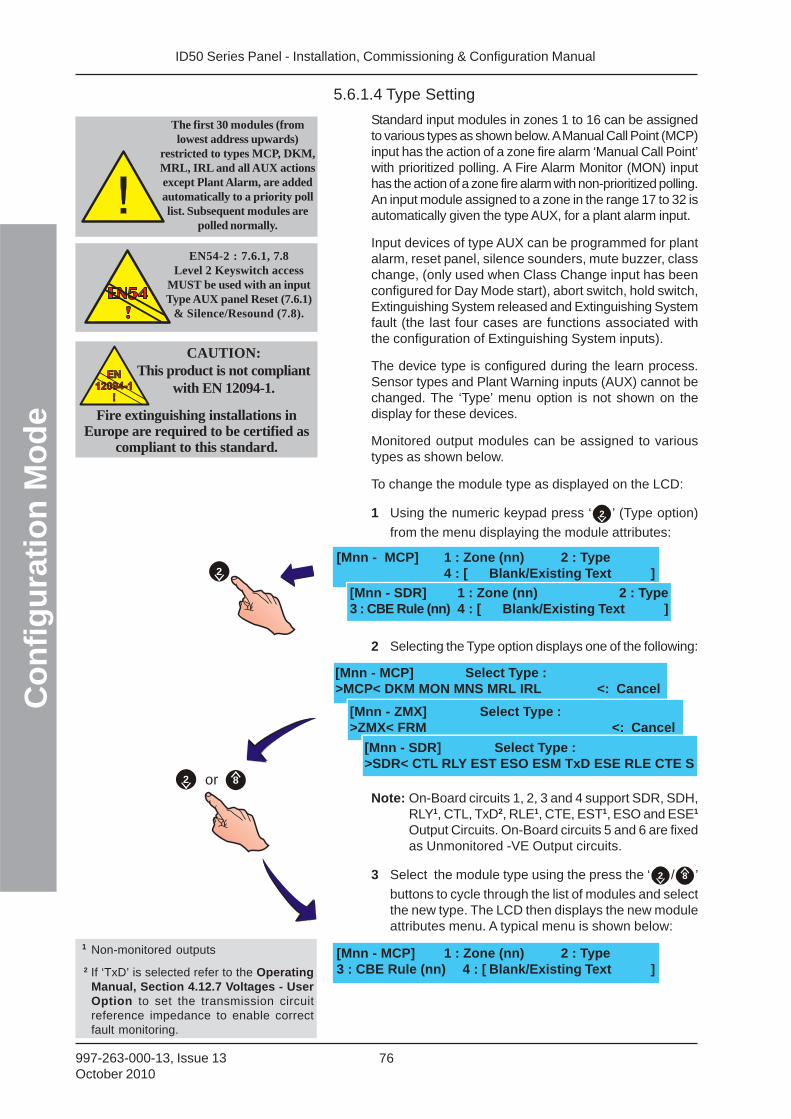
ID50 Series Panel - Installation, Commissioning & Configuration ManualC
on
fig
ura
tio
n M
od
e
76997-263-000-13, Issue 13October 2010
5.6.1.4 Type Setting
Standard input modules in zones 1 to 16 can be assignedto various types as shown below. A Manual Call Point (MCP)input has the action of a zone fire alarm ‘Manual Call Point’with prioritized polling. A Fire Alarm Monitor (MON) inputhas the action of a zone fire alarm with non-prioritized polling.An input module assigned to a zone in the range 17 to 32 isautomatically given the type AUX, for a plant alarm input.
Input devices of type AUX can be programmed for plantalarm, reset panel, silence sounders, mute buzzer, classchange, (only used when Class Change input has beenconfigured for Day Mode start), abort switch, hold switch,Extinguishing System released and Extinguishing Systemfault (the last four cases are functions associated withthe configuration of Extinguishing System inputs).
The device type is configured during the learn process.Sensor types and Plant Warning inputs (AUX) cannot bechanged. The ‘Type’ menu option is not shown on thedisplay for these devices.
Monitored output modules can be assigned to varioustypes as shown below.
To change the module type as displayed on the LCD:
1 Using the numeric keypad press ‘ 2 ’ (Type option)
from the menu displaying the module attributes:
2 Selecting the Type option displays one of the following:
Note: On-Board circuits 1, 2, 3 and 4 support SDR, SDH,RLY1, CTL, TxD2, RLE1, CTE, EST1, ESO and ESE1
Output Circuits. On-Board circuits 5 and 6 are fixedas Unmonitored -VE Output circuits.
3 Select the module type using the press the ‘ 2 / 8 ’
buttons to cycle through the list of modules and selectthe new type. The LCD then displays the new moduleattributes menu. A typical menu is shown below:
[Mnn - MCP] 1 : Zone (nn) 2 : Type4 : [ Blank/Existing Text ]
[Mnn - SDR] 1 : Zone (nn) 2 : Type3 : CBE Rule (nn) 4 : [ Blank/Existing Text ]
2
2
EN54-2 : 7.6.1, 7.8Level 2 Keyswitch access
MUST be used with an inputType AUX panel Reset (7.6.1)
& Silence/Resound (7.8).
The first 30 modules (fromlowest address upwards)
restricted to types MCP, DKM,MRL, IRL and all AUX actionsexcept Plant Alarm, are addedautomatically to a priority polllist. Subsequent modules are
polled normally.
[Mnn - MCP] 1 : Zone (nn) 2 : Type3 : CBE Rule (nn) 4 : [ Blank/Existing Text ]
8or
CAUTION:This product is not compliant
with EN 12094-1.EN
12094-1
!
EN
12094-1
!
Fire extinguishing installations inEurope are required to be certified as
compliant to this standard.
1 Non-monitored outputs
2 If ‘TxD’ is selected refer to the OperatingManual, Section 4.12.7 Voltages - UserOption to set the transmission circuitreference impedance to enable correctfault monitoring.
[Mnn - MCP] Select Type :>MCP< DKM MON MNS MRL IRL <: Cancel
[Mnn - ZMX] Select Type :>ZMX< FRM <: Cancel
[Mnn - SDR] Select Type :>SDR< CTL RLY EST ESO ESM TxD ESE RLE CTE S
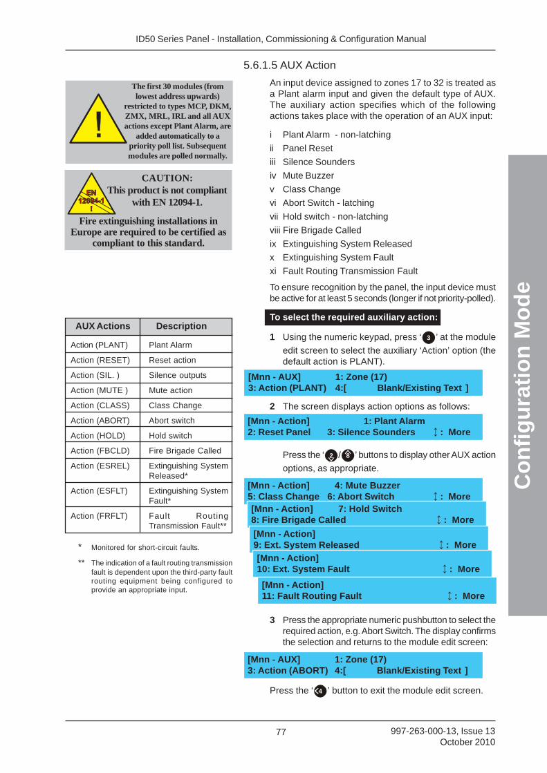
ID50 Series Panel - Installation, Commissioning & Configuration Manual
Co
nfi
gu
rati
on
Mo
de
77 997-263-000-13, Issue 13October 2010
[Mnn - Action] 4: Mute Buzzer5: Class Change 6: Abort Switch : More
5.6.1.5 AUX Action
An input device assigned to zones 17 to 32 is treated asa Plant alarm input and given the default type of AUX.The auxiliary action specifies which of the followingactions takes place with the operation of an AUX input:
i Plant Alarm - non-latching
ii Panel Reset
iii Silence Sounders
iv Mute Buzzer
v Class Change
vi Abort Switch - latching
vii Hold switch - non-latching
viii Fire Brigade Called
ix Extinguishing System Released
x Extinguishing System Fault
xi Fault Routing Transmission Fault
To ensure recognition by the panel, the input device mustbe active for at least 5 seconds (longer if not priority-polled).
To select the required auxiliary action:
1 Using the numeric keypad, press ‘ 3 ’ at the module
edit screen to select the auxiliary ‘Action’ option (thedefault action is PLANT).
2 The screen displays action options as follows:
Press the ‘ 2 / 8 ’ buttons to display other AUX action
options, as appropriate.
3 Press the appropriate numeric pushbutton to select therequired action, e.g. Abort Switch. The display confirmsthe selection and returns to the module edit screen:
Press the ‘ 4 ’ button to exit the module edit screen.
[Mnn - AUX] 1: Zone (17)3: Action (PLANT) 4:[ Blank/Existing Text ]
[Mnn - Action] 1: Plant Alarm2: Reset Panel 3: Silence Sounders : More
[Mnn - AUX] 1: Zone (17)3: Action (ABORT) 4:[ Blank/Existing Text ]
The first 30 modules (fromlowest address upwards)
restricted to types MCP, DKM,ZMX, MRL, IRL and all AUXactions except Plant Alarm, are
added automatically to apriority poll list. Subsequentmodules are polled normally.
CAUTION:This product is not compliant
with EN 12094-1.EN
12094-1
!
EN
12094-1
!
Fire extinguishing installations inEurope are required to be certified as
compliant to this standard.
[Mnn - Action] 7: Hold Switch8: Fire Brigade Called : More
[Mnn - Action]9: Ext. System Released : More
[Mnn - Action]10: Ext. System Fault : More
Action (PLANT) Plant Alarm
Action (RESET) Reset action
Action (SIL. ) Silence outputs
Action (MUTE ) Mute action
Action (CLASS) Class Change
Action (ABORT) Abort switch
Action (HOLD) Hold switch
Action (FBCLD) Fire Brigade Called
Action (ESREL) Extinguishing SystemReleased*
Action (ESFLT) Extinguishing SystemFault*
Action (FRFLT) Fault RoutingTransmission Fault**
AUX Actions Description
* Monitored for short-circuit faults.
** The indication of a fault routing transmissionfault is dependent upon the third-party faultrouting equipment being configured toprovide an appropriate input.
[Mnn - Action]11: Fault Routing Fault : More
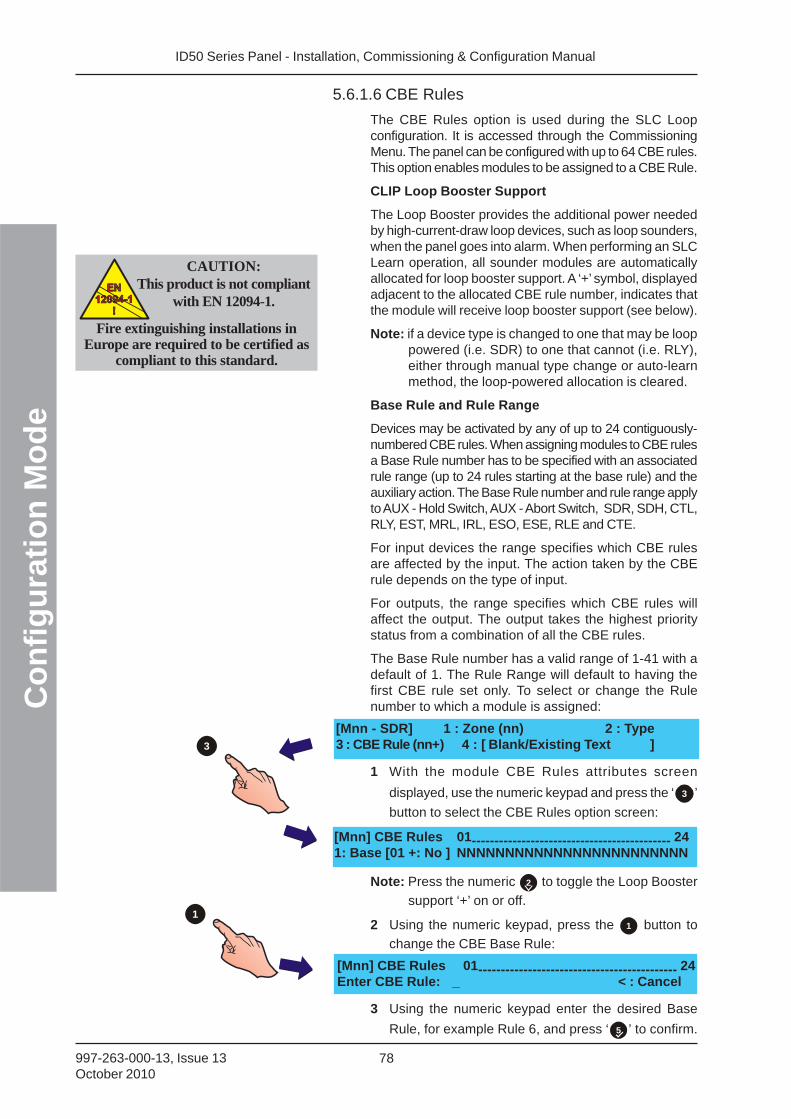
ID50 Series Panel - Installation, Commissioning & Configuration ManualC
on
fig
ura
tio
n M
od
e
78997-263-000-13, Issue 13October 2010
5.6.1.6 CBE Rules
The CBE Rules option is used during the SLC Loopconfiguration. It is accessed through the CommissioningMenu. The panel can be configured with up to 64 CBE rules.This option enables modules to be assigned to a CBE Rule.
CLIP Loop Booster Support
The Loop Booster provides the additional power neededby high-current-draw loop devices, such as loop sounders,when the panel goes into alarm. When performing an SLCLearn operation, all sounder modules are automaticallyallocated for loop booster support. A ‘+’ symbol, displayedadjacent to the allocated CBE rule number, indicates thatthe module will receive loop booster support (see below).
Note: if a device type is changed to one that may be looppowered (i.e. SDR) to one that cannot (i.e. RLY),either through manual type change or auto-learnmethod, the loop-powered allocation is cleared.
Base Rule and Rule Range
Devices may be activated by any of up to 24 contiguously-numbered CBE rules. When assigning modules to CBE rulesa Base Rule number has to be specified with an associatedrule range (up to 24 rules starting at the base rule) and theauxiliary action. The Base Rule number and rule range applyto AUX - Hold Switch, AUX - Abort Switch, SDR, SDH, CTL,RLY, EST, MRL, IRL, ESO, ESE, RLE and CTE.
For input devices the range specifies which CBE rulesare affected by the input. The action taken by the CBErule depends on the type of input.
For outputs, the range specifies which CBE rules willaffect the output. The output takes the highest prioritystatus from a combination of all the CBE rules.
The Base Rule number has a valid range of 1-41 with adefault of 1. The Rule Range will default to having thefirst CBE rule set only. To select or change the Rulenumber to which a module is assigned:
1 With the module CBE Rules attributes screen
displayed, use the numeric keypad and press the ‘ 3 ’
button to select the CBE Rules option screen:
Note: Press the numeric 2 to toggle the Loop Booster
support ‘+’ on or off.
2 Using the numeric keypad, press the 1 button to
change the CBE Base Rule:
3 Using the numeric keypad enter the desired Base
Rule, for example Rule 6, and press ‘ 5 ’ to confirm.
CAUTION:This product is not compliant
with EN 12094-1.EN
12094-1
!
EN
12094-1
!
Fire extinguishing installations inEurope are required to be certified as
compliant to this standard.
[Mnn - SDR] 1 : Zone (nn) 2 : Type3 : CBE Rule (nn+) 4 : [ Blank/Existing Text ]3
1
[Mnn] CBE Rules 01-------------------------------------------- 241: Base [01 +: No ] NNNNNNNNNNNNNNNNNNNNNNNN
[Mnn] CBE Rules 01-------------------------------------------- 24Enter CBE Rule: _ < : Cancel
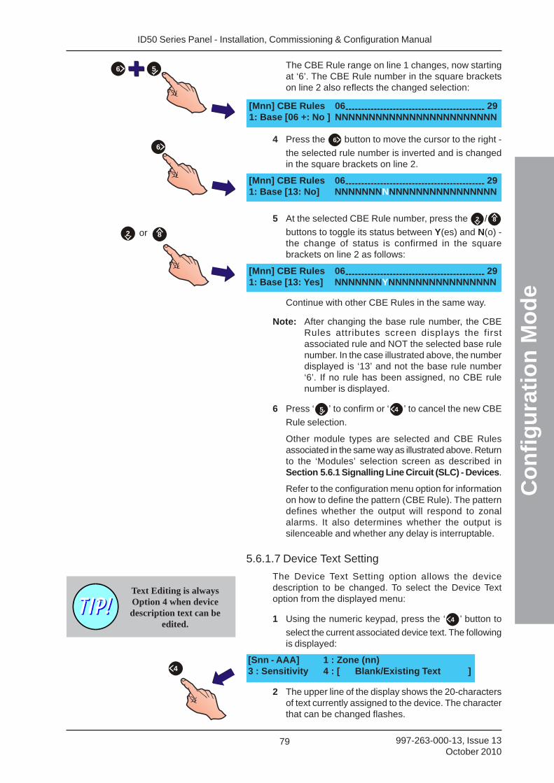
ID50 Series Panel - Installation, Commissioning & Configuration Manual
Co
nfi
gu
rati
on
Mo
de
79 997-263-000-13, Issue 13October 2010
[Mnn] CBE Rules 06-------------------------------------------- 291: Base [13: No] NNNNNNNNNNNNNNNNNNNNNNNN
[Mnn] CBE Rules 06-------------------------------------------- 291: Base [13: Yes] NNNNNNNYNNNNNNNNNNNNNNNN
2 8or
6
The CBE Rule range on line 1 changes, now startingat ‘6’. The CBE Rule number in the square bracketson line 2 also reflects the changed selection:
4 Press the 6 button to move the cursor to the right -
the selected rule number is inverted and is changedin the square brackets on line 2.
5 At the selected CBE Rule number, press the 2 / 8
buttons to toggle its status between Y(es) and N(o) -the change of status is confirmed in the squarebrackets on line 2 as follows:
Continue with other CBE Rules in the same way.
Note: After changing the base rule number, the CBERules attributes screen displays the firstassociated rule and NOT the selected base rulenumber. In the case illustrated above, the numberdisplayed is ‘13’ and not the base rule number‘6’. If no rule has been assigned, no CBE rulenumber is displayed.
6 Press ‘ 5 ’ to confirm or ‘ 4 ’ to cancel the new CBE
Rule selection.
Other module types are selected and CBE Rulesassociated in the same way as illustrated above. Returnto the ‘Modules’ selection screen as described inSection 5.6.1 Signalling Line Circuit (SLC) - Devices.
Refer to the configuration menu option for informationon how to define the pattern (CBE Rule). The patterndefines whether the output will respond to zonalalarms. It also determines whether the output issilenceable and whether any delay is interruptable.
5.6.1.7 Device Text Setting
The Device Text Setting option allows the devicedescription to be changed. To select the Device Textoption from the displayed menu:
1 Using the numeric keypad, press the ‘ 4 ’ button to
select the current associated device text. The followingis displayed:
2 The upper line of the display shows the 20-charactersof text currently assigned to the device. The characterthat can be changed flashes.
[Mnn] CBE Rules 06-------------------------------------------- 291: Base [06 +: No ] NNNNNNNNNNNNNNNNNNNNNNNN
56
Text Editing is alwaysOption 4 when devicedescription text can be
edited.
[Snn - AAA] 1 : Zone (nn)3 : Sensitivity 4 : [ Blank/Existing Text ]4
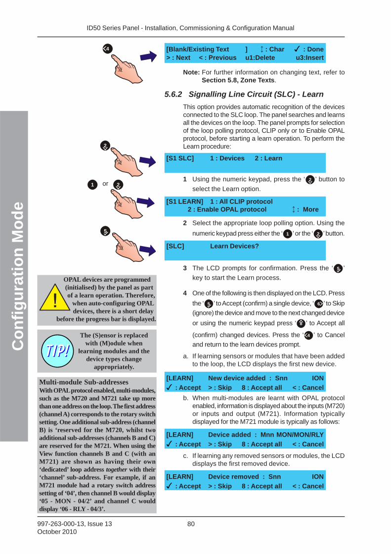
ID50 Series Panel - Installation, Commissioning & Configuration ManualC
on
fig
ura
tio
n M
od
e
80997-263-000-13, Issue 13October 2010
Note: For further information on changing text, refer toSection 5.8, Zone Texts.
5.6.2 Signalling Line Circuit (SLC) - Learn
This option provides automatic recognition of the devicesconnected to the SLC loop. The panel searches and learnsall the devices on the loop. The panel prompts for selectionof the loop polling protocol, CLIP only or to Enable OPALprotocol, before starting a learn operation. To perform theLearn procedure:
1 Using the numeric keypad, press the ‘ 2 ’ button to
select the Learn option.
2 Select the appropriate loop polling option. Using the
numeric keypad press either the ‘ 1 ’ or the ‘ 2 ’ button.
3 The LCD prompts for confirmation. Press the ‘ 5 ’
key to start the Learn process.
4 One of the following is then displayed on the LCD. Press
the ‘ 5 ’ to Accept (confirm) a single device, ‘ 6 ’ to Skip
(ignore) the device and move to the next changed device
or using the numeric keypad press ‘ 8 ’ to Accept all
(confirm) changed devices. Press the ‘ 4 ’ to Cancel
and return to the learn devices prompt.
a. If learning sensors or modules that have been addedto the loop, the LCD displays the first new device.
b. When multi-modules are learnt with OPAL protocolenabled, information is displayed about the inputs (M720)or inputs and output (M721). Information typicallydisplayed for the M721 module is typically as follows:
c. If learning any removed sensors or modules, the LCDdisplays the first removed device.
4
or 2
5
2
1
[SLC] Learn Devices?
[S1 LEARN] 1 : All CLIP protocol2 : Enable OPAL protocol : More
[S1 SLC] 1 : Devices 2 : Learn
[LEARN] New device added : Snn ION
: Accept > : Skip 8 : Accept all < : Cancel
The (S)ensor is replacedwith (M)odule when
learning modules and thedevice types change
appropriately.
[Blank/Existing Text ] : Char : Done> : Next < : Previous u1:Delete u3:Insert
OPAL devices are programmed(initialised) by the panel as partof a learn operation. Therefore,
when auto-configuring OPALdevices, there is a short delay
before the progress bar is displayed.
[LEARN] Device removed : Snn ION
: Accept > : Skip 8 : Accept all < : Cancel
[LEARN] Device added : Mnn MON/MON/RLY
: Accept > : Skip 8 : Accept all < : Cancel
Multi-module Sub-addressesWith OPAL protocol enabled, multi-modules,such as the M720 and M721 take up morethan one address on the loop. The first address(channel A) corresponds to the rotary switchsetting. One additional sub-address (channelB) is ‘reserved for the M720, whilst twoadditional sub-addresses (channels B and C)are reserved for the M721. When using theView function channels B and C (with anM721) are shown as having their own‘dedicated’ loop address together with their‘channel’ sub-address. For example, if anM721 module had a rotary switch addresssetting of ‘04’, then channel B would display‘05 - MON - 04/2’ and channel C woulddisplay ‘06 - RLY - 04/3’.
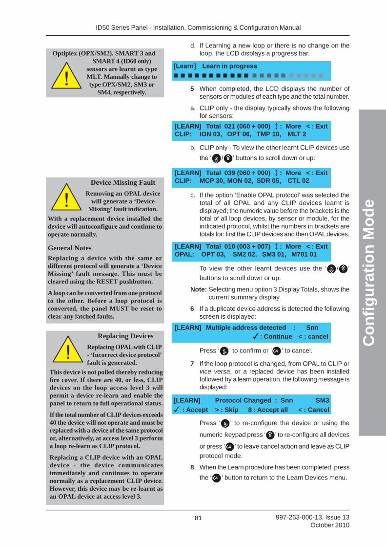
ID50 Series Panel - Installation, Commissioning & Configuration Manual
Co
nfi
gu
rati
on
Mo
de
81 997-263-000-13, Issue 13October 2010
d. If Learning a new loop or there is no change on theloop, the LCD displays a progress bar.
5 When completed, the LCD displays the number ofsensors or modules of each type and the total number.
a. CLIP only - the display typically shows the followingfor sensors:
b. CLIP only - To view the other learnt CLIP devices use
the ‘ 2 / 8 ’ buttons to scroll down or up:
c. If the option ‘Enable OPAL protocol’ was selected thetotal of all OPAL and any CLIP devices learnt isdisplayed; the numeric value before the brackets is thetotal of all loop devices, by sensor or module, for theindicated protocol, whilst the numbers in brackets aretotals for: first the CLIP devices and then OPAL devices.
To view the other learnt devices use the ‘ 2 / 8 ’
buttons to scroll down or up.
Note: Selecting menu option 3 Display Totals, shows thecurrent summary display.
6 If a duplicate device address is detected the followingscreen is displayed:
Press ‘ 5 ’ to confirm or ’ 4 ’ to cancel.
7 If the loop protocol is changed, from OPAL to CLIP orvice versa, or a replaced device has been installedfollowed by a learn operation, the following message isdisplayed:
Press ‘ 5 ’ to re-configure the device or using the
numeric keypad press ‘ 8 ’ to re-configure all devices
or press ’ 4 ’ to leave cancel action and leave as CLIP
protocol mode.
8 When the Learn procedure has been completed, press
the ‘ 4 ’ button to return to the Learn Devices menu.
[LEARN] Total 039 (060 + 000) : More < : ExitCLIP: MCP 30, MON 02, SDR 05, CTL 02
[LEARN] Total 010 (003 + 007) : More < : ExitOPAL: OPT 03, SM2 02, SM3 01, M701 01
[LEARN] Multiple address detected : Snn: Continue < : cancelReplacing Devices
Replacing OPAL with CLIP- ‘Incorrect device protocol’fault is generated.
This device is not polled thereby reducingfire cover. If there are 40, or less, CLIPdevices on the loop access level 3 willpermit a device re-learn and enable thepanel to return to full operational status.
If the total number of CLIP devices exceeds40 the device will not operate and must bereplaced with a device of the same protocolor, alternatively, at access level 3 performa loop re-learn as CLIP protocol.
Replacing a CLIP device with an OPALdevice - the device communicatesimmediately and continues to operatenormally as a replacement CLIP device.However, this device may be re-learnt asan OPAL device at access level 3.
Device Missing Fault
Removing an OPAL devicewill generate a ‘Device
Missing’ fault indication.
With a replacement device installed thedevice will autoconfigure and continue tooperate normally.
General Notes
Replacing a device with the same ordifferent protocol will generate a ‘DeviceMissing’ fault message. This must becleared using the RESET pushbutton.
A loop can be converted from one protocolto the other. Before a loop protocol isconverted, the panel MUST be reset toclear any latched faults.
[LEARN] Protocol Changed : Snn SM3
: Accept > : Skip 8 : Accept all < : Cancel
[LEARN] Total 021 (060 + 000) : More < : ExitCLIP: ION 03, OPT 06, TMP 10, MLT 2
[Learn] Learn in progress
Optiplex (OPX/SM2), SMART 3 andSMART 4 (ID60 only)
sensors are learnt as typeMLT. Manually change totype OPX/SM2, SM3 or
SM4, respectively.
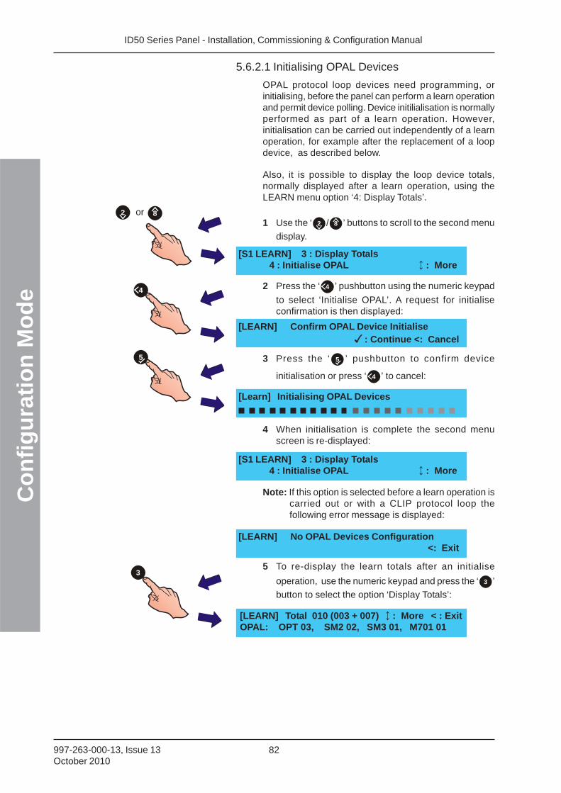
ID50 Series Panel - Installation, Commissioning & Configuration ManualC
on
fig
ura
tio
n M
od
e
82997-263-000-13, Issue 13October 2010
5.6.2.1 Initialising OPAL Devices
OPAL protocol loop devices need programming, orinitialising, before the panel can perform a learn operationand permit device polling. Device initilialisation is normallyperformed as part of a learn operation. However,initialisation can be carried out independently of a learnoperation, for example after the replacement of a loopdevice, as described below.
Also, it is possible to display the loop device totals,normally displayed after a learn operation, using theLEARN menu option ‘4: Display Totals’.
1 Use the ‘ 2 / 8 ’ buttons to scroll to the second menu
display.
3 Press the ‘ 5 ’ pushbutton to confirm device
initialisation or press ‘ 4 ’ to cancel:
2 Press the ‘ 4 ’ pushbutton using the numeric keypad
to select ‘Initialise OPAL’. A request for initialiseconfirmation is then displayed:
4 When initialisation is complete the second menuscreen is re-displayed:
5 To re-display the learn totals after an initialise
operation, use the numeric keypad and press the ‘ 3 ’
button to select the option ‘Display Totals’:
Note: If this option is selected before a learn operation iscarried out or with a CLIP protocol loop thefollowing error message is displayed:
5
4
[Learn] Initialising OPAL Devices
[S1 LEARN] 3 : Display Totals4 : Initialise OPAL : More
[LEARN] Confirm OPAL Device Initialise: Continue <: Cancel
[S1 LEARN] 3 : Display Totals4 : Initialise OPAL : More
[LEARN] Total 010 (003 + 007) : More < : ExitOPAL: OPT 03, SM2 02, SM3 01, M701 01
3
2 8or
[LEARN] No OPAL Devices Configuration<: Exit
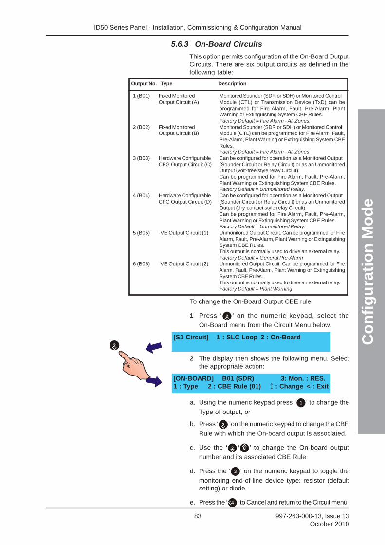
ID50 Series Panel - Installation, Commissioning & Configuration Manual
Co
nfi
gu
rati
on
Mo
de
83 997-263-000-13, Issue 13October 2010
5.6.3 On-Board Circuits
This option permits configuration of the On-Board OutputCircuits. There are six output circuits as defined in thefollowing table:
To change the On-Board Output CBE rule:
1 Press ‘ 2 ’ on the numeric keypad, select the
On-Board menu from the Circuit Menu below.
2 The display then shows the following menu. Selectthe appropriate action:
a. Using the numeric keypad press ‘ 1 ’ to change the
Type of output, or
b. Press ‘ 2 ’ on the numeric keypad to change the CBE
Rule with which the On-board output is associated.
c. Use the ‘ 2 / 8 ’ to change the On-board output
number and its associated CBE Rule.
d. Press the ‘ 3 ’ on the numeric keypad to toggle the
monitoring end-of-line device type: resistor (defaultsetting) or diode.
e. Press the ‘ 4 ’ to Cancel and return to the Circuit menu.
Output No. Type Description
1 (B01) Fixed Monitored Monitored Sounder (SDR or SDH) or Monitored ControlOutput Circuit (A) Module (CTL) or Transmission Device (TxD) can be
programmed for Fire Alarm, Fault, Pre-Alarm, PlantWarning or Extinguishing System CBE Rules.Factory Default = Fire Alarm - All Zones.
2 (B02) Fixed Monitored Monitored Sounder (SDR or SDH) or Monitored ControlOutput Circuit (B) Module (CTL) can be programmed for Fire Alarm, Fault,
Pre-Alarm, Plant Warning or Extinguishing System CBERules.Factory Default = Fire Alarm - All Zones.
3 (B03) Hardware Configurable Can be configured for operation as a Monitored OutputCFG Output Circuit (C) (Sounder Circuit or Relay Circuit) or as an Unmonitored
Output (volt-free style relay Circuit).Can be programmed for Fire Alarm, Fault, Pre-Alarm,Plant Warning or Extinguishing System CBE Rules.Factory Default = Unmonitored Relay.
4 (B04) Hardware Configurable Can be configured for operation as a Monitored OutputCFG Output Circuit (D) (Sounder Circuit or Relay Circuit) or as an Unmonitored
Output (dry-contact style relay Circuit).Can be programmed for Fire Alarm, Fault, Pre-Alarm,Plant Warning or Extinguishing System CBE Rules.Factory Default = Unmonitored Relay.
5 (B05) -VE Output Circuit (1) Unmonitored Output Circuit. Can be programmed for FireAlarm, Fault, Pre-Alarm, Plant Warning or ExtinguishingSystem CBE Rules.This output is normally used to drive an external relay.Factory Default = General Pre-Alarm
6 (B06) -VE Output Circuit (2) Unmonitored Output Circuit. Can be programmed for FireAlarm, Fault, Pre-Alarm, Plant Warning or ExtinguishingSystem CBE Rules.This output is normally used to drive an external relay.Factory Default = Plant Warning
[S1 Circuit] 1 : SLC Loop 2 : On-Board
[ON-BOARD] B01 (SDR) 3: Mon. : RES.1 : Type 2 : CBE Rule (01) : Change < : Exit
2
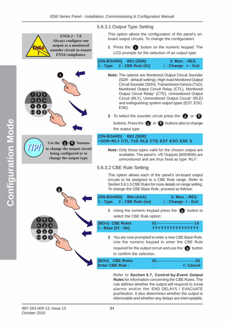
ID50 Series Panel - Installation, Commissioning & Configuration ManualC
on
fig
ura
tio
n M
od
e
84997-263-000-13, Issue 13October 2010
5.6.3.1 Output Type Setting
This option allows the configuration of the panel’s on-board output circuits. To change the configuration:
1 Press the ‘ 1 ’ button on the numeric keypad. The
LCD prompts for the selection of an output type:
Note: The options are Monitored Output Circuit Sounder(SDR - default setting), High-load Monitored OutputCircuit Sounder (SDH), Transmission Device (TxD),Monitored Output Circuit Relay (CTL), MonitoredOutput Circuit Relay1 (CTE), Unmonitored OutputCircuit (RLY), Unmonitored Output Circuit1 (RLE)and extinguishing system output types (EST, ESO,ESE).
2 To select the sounder circuit press the ‘ 2 ’ or ‘ 8 ’
buttons. Press the ‘ 2 ’ or ‘ 8 ’ buttons also to change
the output type.
Note: Only those types valid for the chosen output areavailable. The panel’s -VE Outputs (B05/B06) areunmonitored and are thus fixed as type ‘RLY’.
5.6.3.2 CBE Rule Setting
This option allows each of the panel’s on-board outputcircuits to be assigned to a CBE Rule range. Refer toSection 5.6.1.5 CBE Rules for more details on range setting.To change the CBE Base Rule, proceed as follows:
1 Using the numeric keypad press the ‘ 2 ‘ button to
select the CBE Rule option:
2 You are now prompted to enter a new CBE Base Rule.Use the numeric keypad to enter the CBE Rule
required for the output circuit and use the ‘ 5 ’ button
to confirm the selection.
Refer to Section 5.7, Control-by-Event OutputRules for information concerning the CBE Rules. Therule defines whether the output will respond to zonalalarms and/or the END DELAYS / EVACUATEpushbutton. It also determines whether the output issilenceable and whether any delays are interruptable.
EN54-2 : 7.8Always configure oneoutput as a monitored
sounder circuit to ensureEN54 compliance
[ON-BOARD] B01 (SDR) 3: Mon. : RES.1 : Type 2 : CBE Rule (01) : Change < : Exit
[ON-BOARD] B01 (SDR)>SDR<RLY CTL TxD RLE CTE EST ESO ESE S
[ON-BOARD] B0n (AAA) 3: Mon. : RES.1 : Type 2 : CBE Rule (nn) : Change < : Exit
Use the ‘ 2 / 8 ’ buttons
to change the output circuitbeing configured or to
change the output type.
1
2
[BOn] CBE Rules 01-- - - - - - - - - - - --- - - - - - - -161 : Base [01 : No] YYYYYYYYYYYYYYYY
[BOn] CBE Rules 01--- - - - - - - - - - - - - - - - - - - - -24Enter CBE Rule : _ <: Cancel
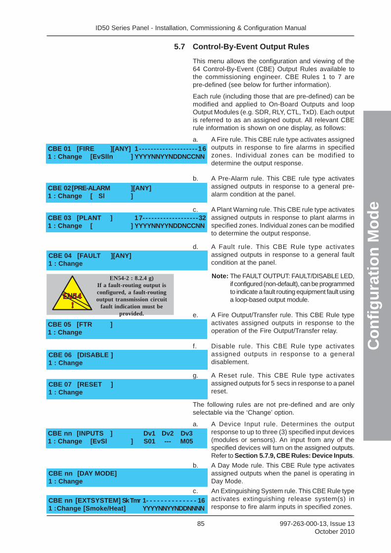
ID50 Series Panel - Installation, Commissioning & Configuration Manual
Co
nfi
gu
rati
on
Mo
de
85 997-263-000-13, Issue 13October 2010
5.7 Control-By-Event Output Rules
This menu allows the configuration and viewing of the64 Control-By-Event (CBE) Output Rules available tothe commissioning engineer. CBE Rules 1 to 7 arepre-defined (see below for further information).
Each rule (including those that are pre-defined) can bemodified and applied to On-Board Outputs and loopOutput Modules (e.g. SDR, RLY, CTL, TxD). Each outputis referred to as an assigned output. All relevant CBErule information is shown on one display, as follows:
a. A Fire rule. This CBE rule type activates assignedoutputs in response to fire alarms in specifiedzones. Individual zones can be modified todetermine the output response.
b. A Pre-Alarm rule. This CBE rule type activatesassigned outputs in response to a general pre-alarm condition at the panel.
c. A Plant Warning rule. This CBE rule type activatesassigned outputs in response to plant alarms inspecified zones. Individual zones can be modifiedto determine the output response.
d. A Fault rule. This CBE Rule type activatesassigned outputs in response to a general faultcondition at the panel.
Note: The FAULT OUTPUT: FAULT/DISABLE LED,if configured (non-default), can be programmedto indicate a fault routing equipment fault usinga loop-based output module.
e. A Fire Output/Transfer rule. This CBE Rule typeactivates assigned outputs in response to theoperation of the Fire Output/Transfer relay.
f. Disable rule. This CBE Rule type activatesassigned outputs in response to a generaldisablement.
g. A Reset rule. This CBE Rule type activatesassigned outputs for 5 secs in response to a panelreset.
The following rules are not pre-defined and are onlyselectable via the ‘Change’ option.
a. A Device Input rule. Determines the outputresponse to up to three (3) specified input devices(modules or sensors). An input from any of thespecified devices will turn on the assigned outputs.Refer to Section 5.7.9, CBE Rules: Device Inputs.
b. A Day Mode rule. This CBE Rule type activatesassigned outputs when the panel is operating inDay Mode.
c. An Extinguishing System rule. This CBE Rule typeactivates extinguishing release system(s) inresponse to fire alarm inputs in specified zones.
CBE 01 [FIRE ][ANY] 1- - - - - - - - - - - - - - - - - - - -161 : Change [EvSlln ] YYYYNNYYNDDNCCNN
CBE 02[PRE-ALARM ][ANY]1 : Change [ Sl ]
CBE 03 [PLANT ] 17- - - - - - - - - - - - - - - - - - -321 : Change [ ] YYYYNNYYNDDNCCNN
CBE 04 [FAULT ][ANY]1 : Change
CBE 05 [FTR ]1 : Change
CBE 07 [RESET ]1 : Change
CBE nn [INPUTS ] Dv1 Dv2 Dv31 : Change [EvSl ] S01 --- M05
CBE nn [DAY MODE]1 : Change
CBE nn [EXTSYSTEM] Sk Tmr 1- - - - - - - - - - - - - - 161 :Change [Smoke/Heat] YYYYNNYYNDDNNNN
EN54-2 : 8.2.4 g)If a fault-routing output isconfigured, a fault-routingoutput transmission circuit
fault indication must beprovided.
CBE 06 [DISABLE ]1 : Change
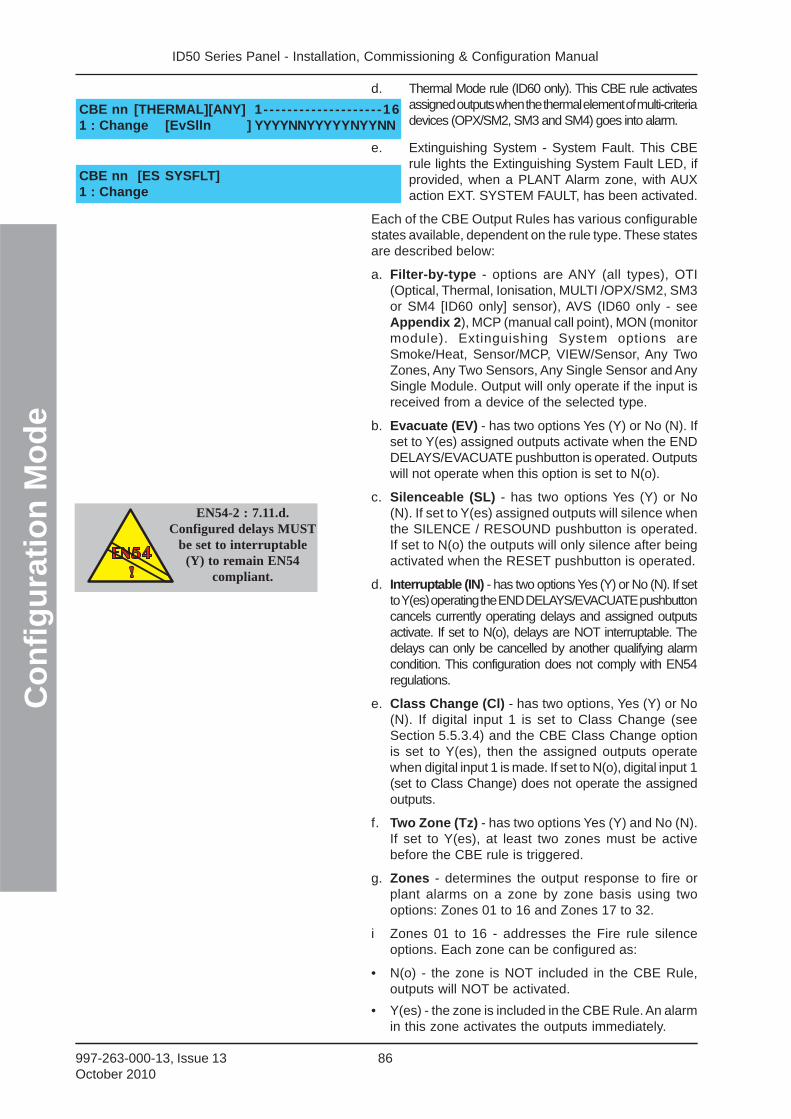
ID50 Series Panel - Installation, Commissioning & Configuration ManualC
on
fig
ura
tio
n M
od
e
86997-263-000-13, Issue 13October 2010
d. Thermal Mode rule (ID60 only). This CBE rule activatesassigned outputs when the thermal element of multi-criteriadevices (OPX/SM2, SM3 and SM4) goes into alarm.
e. Extinguishing System - System Fault. This CBErule lights the Extinguishing System Fault LED, ifprovided, when a PLANT Alarm zone, with AUXaction EXT. SYSTEM FAULT, has been activated.
Each of the CBE Output Rules has various configurablestates available, dependent on the rule type. These statesare described below:
a. Filter-by-type - options are ANY (all types), OTI(Optical, Thermal, Ionisation, MULTI /OPX/SM2, SM3or SM4 [ID60 only] sensor), AVS (ID60 only - seeAppendix 2), MCP (manual call point), MON (monitormodule). Extinguishing System options areSmoke/Heat, Sensor/MCP, VIEW/Sensor, Any TwoZones, Any Two Sensors, Any Single Sensor and AnySingle Module. Output will only operate if the input isreceived from a device of the selected type.
b. Evacuate (EV) - has two options Yes (Y) or No (N). Ifset to Y(es) assigned outputs activate when the ENDDELAYS/EVACUATE pushbutton is operated. Outputswill not operate when this option is set to N(o).
c. Silenceable (SL) - has two options Yes (Y) or No(N). If set to Y(es) assigned outputs will silence whenthe SILENCE / RESOUND pushbutton is operated.If set to N(o) the outputs will only silence after beingactivated when the RESET pushbutton is operated.
d. Interruptable (IN) - has two options Yes (Y) or No (N). If setto Y(es) operating the END DELAYS/EVACUATE pushbuttoncancels currently operating delays and assigned outputsactivate. If set to N(o), delays are NOT interruptable. Thedelays can only be cancelled by another qualifying alarmcondition. This configuration does not comply with EN54regulations.
e. Class Change (Cl) - has two options, Yes (Y) or No(N). If digital input 1 is set to Class Change (seeSection 5.5.3.4) and the CBE Class Change optionis set to Y(es), then the assigned outputs operatewhen digital input 1 is made. If set to N(o), digital input 1(set to Class Change) does not operate the assignedoutputs.
f. Two Zone (Tz) - has two options Yes (Y) and No (N).If set to Y(es), at least two zones must be activebefore the CBE rule is triggered.
g. Zones - determines the output response to fire orplant alarms on a zone by zone basis using twooptions: Zones 01 to 16 and Zones 17 to 32.
i Zones 01 to 16 - addresses the Fire rule silenceoptions. Each zone can be configured as:
• N(o) - the zone is NOT included in the CBE Rule,outputs will NOT be activated.
• Y(es) - the zone is included in the CBE Rule. An alarmin this zone activates the outputs immediately.
EN54-2 : 7.11.d.Configured delays MUST
be set to interruptable(Y) to remain EN54
compliant.
CBE nn [THERMAL][ANY] 1- - - - - - - - - - - - - - - - - - - -161 : Change [EvSlln ] YYYYNNYYYYYNYYNN
CBE nn [ES SYSFLT]1 : Change

ID50 Series Panel - Installation, Commissioning & Configuration Manual
Co
nfi
gu
rati
on
Mo
de
87 997-263-000-13, Issue 13October 2010
• (P)ulsed - the zone is included in the CBE Rule. Analarm in this zone will activate outputs immediatelyin pulsed mode. This mode is overridden if an alarmoccurs in any zone that is included in this rule and forwhich Pulse Mode is not selected, also if a device isassigned to multiple CBE rules and a rule for whichPulse Mode is not selected becomes active.
ii Zones 17 to 32 - addresses the plant warning rulesilence options. These zones can be configured inthe same manner as described for zones 01 to 16.
h. Soak Timer (Sk Tmr) - has two options Yes (Y) orNo (N). If set to Y(es) the associated extinguishingoutput is active only for the time specified in theSystem Soak Timer Setup menu.
To select the CBE Rule menu, proceed as follows:
1 With the Commissioning menu displayed, press the
‘ 3 ’ button on the numeric keypad.
2 The LCD prompts you to enter a CBE Rule numberas shown below:
Enter the required CBE Rule number using the numeric
keypad and confirm by pressing the ‘ 5 ’ button.
3 The LCD then displays the selected CBE Rule’s currentconfiguration and a menu option to allow changes tothe rule. The displayed configurable options dependupon the rule type. To change the rule configuration
press the ‘ 1 ’ button on the numeric keypad.
Note: You can use the ‘ 2 / 8 ’ buttons to step through
each of the 64 CBE Rules.
4 At the menu below, use the numeric keypad to selectthe option that requires changing.
Note: Selectable options are dependent upon the typeof the current CBE Rule.
[S1 COMM] 1 : Setup 2 : Circuit3 : CBE Rules 4 : Zones 5 : Access : More
CBE 01[FIRE ][ANY] 1- - - - - - - - - - - - - - - - - - - -161 : Change [EvSlln ] YYYYNNYYNDDNCCNN
[CBE Rule] Select Rule No ____
CBE Rule:01 1:Type 2:Filter 3:Evac4:Silence 5:Interrupt : More
CBE Rule:01 6:Class Change 7:Two Zone9:Zones : More
3
or 82
5
• (D)elay - the zone is included in the CBE Rule. Analarm in this zone will activate outputs after a delay.Not available for Fire rules if Two Zone is selected.Extinguishing System rules default to Delay.
• (C)oincidence - the zone is included in the CBE Rule.Two alarms in this zone will activate outputs.
CAUTION:This product is not compliant
with EN 12094-1.EN
12094-1
!
EN
12094-1
!
Fire extinguishing installations inEurope are required to be certified as
compliant to this standard.
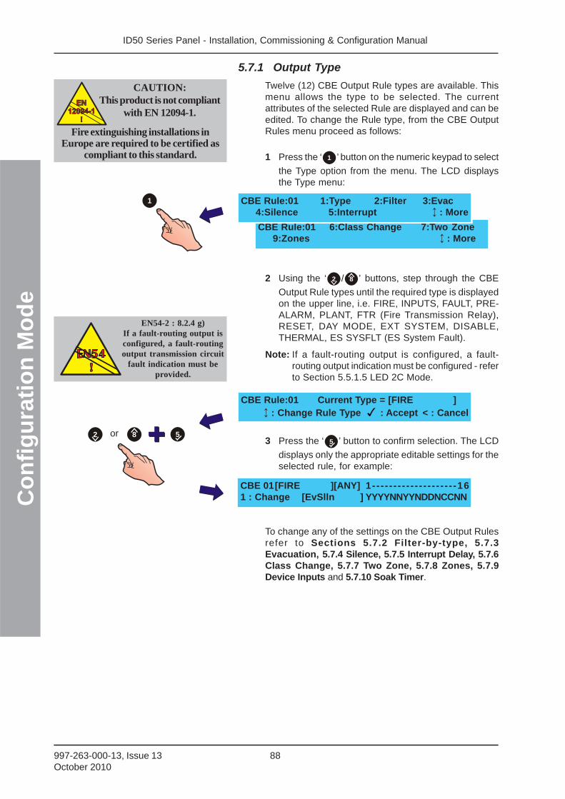
ID50 Series Panel - Installation, Commissioning & Configuration ManualC
on
fig
ura
tio
n M
od
e
88997-263-000-13, Issue 13October 2010
CBE Rule:01 6:Class Change 7:Two Zone9:Zones : More
5.7.1 Output Type
Twelve (12) CBE Output Rule types are available. Thismenu allows the type to be selected. The currentattributes of the selected Rule are displayed and can beedited. To change the Rule type, from the CBE OutputRules menu proceed as follows:
1 Press the ‘ 1 ’ button on the numeric keypad to select
the Type option from the menu. The LCD displaysthe Type menu:
2 Using the ‘ 2 / 8 ’ buttons, step through the CBE
Output Rule types until the required type is displayedon the upper line, i.e. FIRE, INPUTS, FAULT, PRE-ALARM, PLANT, FTR (Fire Transmission Relay),RESET, DAY MODE, EXT SYSTEM, DISABLE,THERMAL, ES SYSFLT (ES System Fault).
Note: If a fault-routing output is configured, a fault-routing output indication must be configured - referto Section 5.5.1.5 LED 2C Mode.
3 Press the ‘ 5 ’ button to confirm selection. The LCD
displays only the appropriate editable settings for theselected rule, for example:
To change any of the settings on the CBE Output Rulesrefer to Sections 5.7.2 Filter-by-type, 5.7.3Evacuation, 5.7.4 Silence, 5.7.5 Interrupt Delay, 5.7.6Class Change, 5.7.7 Two Zone, 5.7.8 Zones, 5.7.9Device Inputs and 5.7.10 Soak Timer.
CBE 01[FIRE ][ANY] 1- - - - - - - - - - - - - - - - - - - -161 : Change [EvSlln ] YYYYNNYYNDDNCCNN
CBE Rule:01 Current Type = [FIRE ] : Change Rule Type : Accept < : Cancel
5or 82
1
EN54-2 : 8.2.4 g)If a fault-routing output isconfigured, a fault-routingoutput transmission circuit
fault indication must beprovided.
CBE Rule:01 1:Type 2:Filter 3:Evac4:Silence 5:Interrupt : More
CAUTION:This product is not compliant
with EN 12094-1.EN
12094-1
!
EN
12094-1
!
Fire extinguishing installations inEurope are required to be certified as
compliant to this standard.
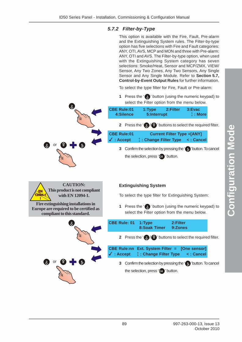
ID50 Series Panel - Installation, Commissioning & Configuration Manual
Co
nfi
gu
rati
on
Mo
de
89 997-263-000-13, Issue 13October 2010
5.7.2 Filter-by-Type
This option is available with the Fire, Fault, Pre-alarmand the Extinguishing System rules. The Filter-by-typeoption has five selections with Fire and Fault categories:ANY, OTI, AVS, MCP and MON and three with Pre-alarm:ANY, OTI and AVS. The Filter-by-type option, when usedwith the Extinguishing System category has sevenselections: Smoke/Heat, Sensor and MCP/ZMX, VIEW/Sensor, Any Two Zones, Any Two Sensors, Any SingleSensor and Any Single Module. Refer to Section 5.7,Control-by-Event Output Rules for further information.
To select the type filter for Fire, Fault or Pre-alarm:
1 Press the ‘ 2 ’ button (using the numeric keypad) to
select the Filter option from the menu below.
2 Press the ‘ 2 / 8 ’ buttons to select the required filter.
3 Confirm the selection by pressing the ‘ 5 ’ button. To cancel
the selection, press ‘ 4 ’ button.
Extinguishing System
To select the type filter for Extinguishing System:
1 Press the ‘ 2 ’ button (using the numeric keypad) to
select the Filter option from the menu below.
2 Press the ‘ 2 / 8 ’ buttons to select the required filter.
3 Confirm the selection by pressing the ‘ 5 ’ button. To cancel
the selection, press ‘ 4 ’ button.
CBE Rule:01 1:Type 2:Filter 3:Evac4:Silence 5:Interrupt : More
CBE Rule:01 Current Filter Type =[ANY]
: Accept : Change Filter Type < : Cancel5
2
or 82
CBE Rule: 01 1:Type 2:Filter8:Soak Timer 9:Zones
CBE Rule:nn Ext. System Filter = [One sensor] : Accept : Change Filter Type < : Cancel
5
2
or 82
CAUTION:This product is not compliant
with EN 12094-1.EN
12094-1
!
EN
12094-1
!
Fire extinguishing installations inEurope are required to be certified as
compliant to this standard.
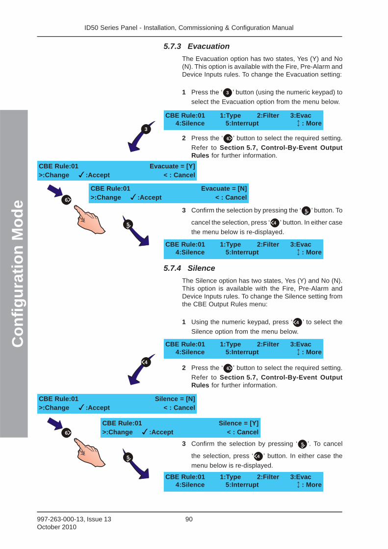
ID50 Series Panel - Installation, Commissioning & Configuration ManualC
on
fig
ura
tio
n M
od
e
90997-263-000-13, Issue 13October 2010
5.7.3 Evacuation
The Evacuation option has two states, Yes (Y) and No(N). This option is available with the Fire, Pre-Alarm andDevice Inputs rules. To change the Evacuation setting:
1 Press the ‘ 3 ’ button (using the numeric keypad) to
select the Evacuation option from the menu below.
2 Press the ‘ 6 ’ button to select the required setting.
Refer to Section 5.7, Control-By-Event OutputRules for further information.
3 Confirm the selection by pressing the ‘ 5 ’ button. To
cancel the selection, press ‘ 4 ’ button. In either case
the menu below is re-displayed.
5.7.4 Silence
The Silence option has two states, Yes (Y) and No (N).This option is available with the Fire, Pre-Alarm andDevice Inputs rules. To change the Silence setting fromthe CBE Output Rules menu:
1 Using the numeric keypad, press ‘ 4 ’ to select the
Silence option from the menu below.
2 Press the ‘ 6 ’ button to select the required setting.
Refer to Section 5.7, Control-By-Event OutputRules for further information.
3 Confirm the selection by pressing ‘ 5 ’. To cancel
the selection, press ‘ 4 ’ button. In either case the
menu below is re-displayed.
CBE Rule:01 1:Type 2:Filter 3:Evac4:Silence 5:Interrupt : More
CBE Rule:01 Evacuate = [Y]>:Change :Accept < : Cancel
CBE Rule:01 Evacuate = [N]>:Change :Accept < : Cancel
CBE Rule:01 1:Type 2:Filter 3:Evac4:Silence 5:Interrupt : More
CBE Rule:01 1:Type 2:Filter 3:Evac4:Silence 5:Interrupt : More
CBE Rule:01 Silence = [N]>:Change :Accept < : Cancel
CBE Rule:01 Silence = [Y]>:Change :Accept < : Cancel
CBE Rule:01 1:Type 2:Filter 3:Evac4:Silence 5:Interrupt : More
6
3
5
6
5
4
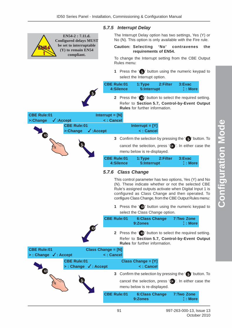
ID50 Series Panel - Installation, Commissioning & Configuration Manual
Co
nfi
gu
rati
on
Mo
de
91 997-263-000-13, Issue 13October 2010
5.7.5 Interrupt Delay
The Interrupt Delay option has two settings, Yes (Y) orNo (N). This option is only available with the Fire rule.
Caution: Selecting ‘No’ contravenes therequirements of EN54.
To change the Interrupt setting from the CBE OutputRules menu:
1 Press the ‘ 5 ’ button using the numeric keypad to
select the Interrupt option.
2 Press the ‘ 6 ’ button to select the required setting.
Refer to Section 5.7, Control-by-Event OutputRules for further information.
3 Confirm the selection by pressing the ‘ 5 ’ button. To
cancel the selection, press ‘ 4 ’. In either case the
menu below is re-displayed.
5.7.6 Class Change
This control parameter has two options, Yes (Y) and No(N). These indicate whether or not the selected CBERule’s assigned outputs activate when Digital Input 1 isconfigured as Class Change and then operated. Toconfigure Class Change, from the CBE Output Rules menu:
1 Press the ‘ 6 ’ button using the numeric keypad to
select the Class Change option.
2 Press the ‘ 6 ’ button to select the required setting.
Refer to Section 5.7, Control-by-Event OutputRules for further information.
3 Confirm the selection by pressing the ‘ 5 ’ button. To
cancel the selection, press ‘ 4 ’. In either case the
menu below is re-displayed.
CBE Rule:01 1:Type 2:Filter 3:Evac4:Silence 5:Interrupt : More
CBE Rule:01 Interrupt = [N]>:Change :Accept < : Cancel
CBE Rule:01 Interrupt = [Y]>:Change :Accept < : Cancel
CBE Rule:01 1:Type 2:Filter 3:Evac4:Silence 5:Interrupt : More
CBE Rule:01 6:Class Change 7:Two Zone9:Zones : More
CBE Rule:01 Class Change = [N]> : Change : Accept < : Cancel
CBE Rule:01 Class Change = [Y]> : Change : Accept < : Cancel
CBE Rule:01 6:Class Change 7:Two Zone9:Zones : More
6
5
5
6
5
6
EN54-2 : 7.11.d.Configured delays MUST
be set to interruptable(Y) to remain EN54
compliant.
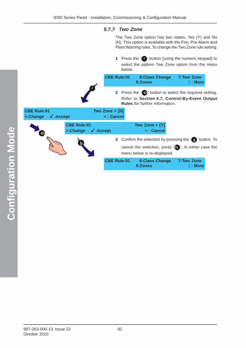
ID50 Series Panel - Installation, Commissioning & Configuration ManualC
on
fig
ura
tio
n M
od
e
92997-263-000-13, Issue 13October 2010
5.7.7 Two Zone
The Two Zone option has two states, Yes (Y) and No(N). This option is available with the Fire, Pre-Alarm andPlant Warning rules. To change the Two Zone rule setting:
1 Press the ‘ 7 ’ button (using the numeric keypad) to
select the pattern Two Zone option from the menubelow.
2 Press the ‘ 6 ’ button to select the required setting.
Refer to Section 5.7, Control-By-Event OutputRules for further information.
3 Confirm the selection by pressing the ‘ 5 ’ button. To
cancel the selection, press ‘ 4 ’. In either case the
menu below is re-displayed.
CBE Rule:01 6:Class Change 7:Two Zone9:Zones : More
CBE Rule:01 Two Zone = [N]>:Change :Accept < : Cancel
CBE Rule:01 Two Zone = [Y]>:Change :Accept < : Cancel
CBE Rule:01 6:Class Change 7:Two Zone9:Zones : More
6
5
7
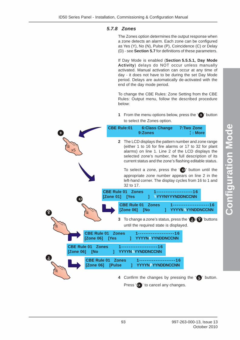
ID50 Series Panel - Installation, Commissioning & Configuration Manual
Co
nfi
gu
rati
on
Mo
de
93 997-263-000-13, Issue 13October 2010
5.7.8 Zones
The Zones option determines the output response whena zone detects an alarm. Each zone can be configuredas Yes (Y), No (N), Pulse (P), Coincidence (C) or Delay(D) - see Section 5.7 for definitions of these parameters.
If Day Mode is enabled (Section 5.5.5.1, Day ModeActivity) delays do NOT occur unless manuallyactivated. Manual activation can occur at any time ofday - it does not have to be during the set Day Modeperiod. Delays are automatically de-activated with theend of the day mode period.
To change the CBE Rules: Zone Setting from the CBERules: Output menu, follow the described procedurebelow:
1 From the menu options below, press the ‘ 9 ’ button
to select the Zones option.
2 The LCD displays the pattern number and zone range(either 1 to 16 for fire alarms or 17 to 32 for plantalarms) on line 1. Line 2 of the LCD displays theselected zone’s number, the full description of itscurrent status and the zone’s flashing editable status.
To select a zone, press the ‘ 6 ’ button until the
appropriate zone number appears on line 2 in theleft-hand corner. The display cycles from 16 to 1 and32 to 17.
3 To change a zone’s status, press the ‘ 2 / 8 ’ buttons
until the required state is displayed.
4 Confirm the changes by pressing the ‘ 5 ’ button.
Press ‘ 4 ’ to cancel any changes.
CBE Rule:01 6:Class Change 7:Two Zone9:Zones : More
CBE Rule 01 Zones 1-- - - - - - - - - - - - - - - - - - -16[Zone 01] [Yes ] YYYYNYYYNDDNCCNN
CBE Rule 01 Zones 1-- - - - - - - - - - - - - - - - - - -16[Zone 06] [No ] YYYYNNYYNDDNCCNN
CBE Rule 01 Zones 1-- - - - - - - - - - - - - - - - - - -16[Zone 06] [No ] YYYYNNYYNDDNCCNN
CBE Rule 01 Zones 1-- - - - - - - - - - - - - - - - - - -16[Zone 06] [Yes ] YYYYNYYYNDDNCCNN
CBE Rule 01 Zones 1-- - - - - - - - - - - - - - - - - - -16[Zone 06] [Pulse ] YYYYNPYYNDDNCCNN
6
2
8
x5
9
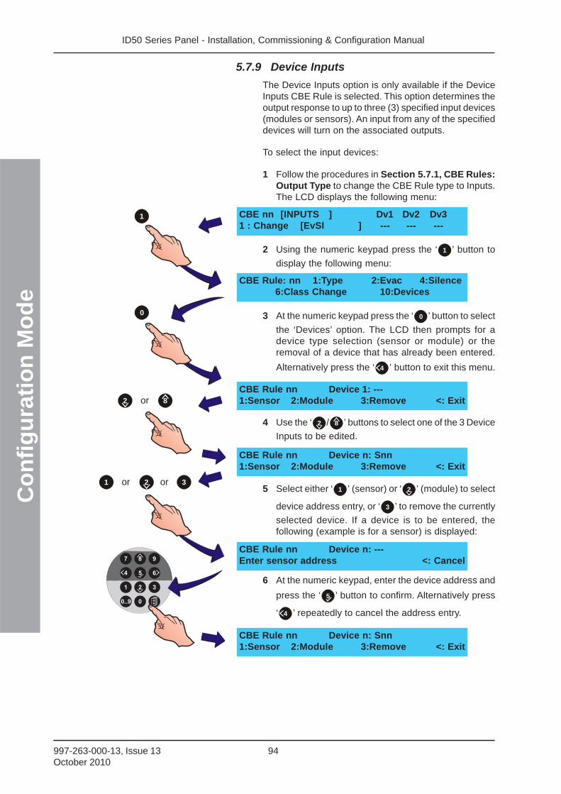
ID50 Series Panel - Installation, Commissioning & Configuration ManualC
on
fig
ura
tio
n M
od
e
94997-263-000-13, Issue 13October 2010
5.7.9 Device Inputs
The Device Inputs option is only available if the DeviceInputs CBE Rule is selected. This option determines theoutput response to up to three (3) specified input devices(modules or sensors). An input from any of the specifieddevices will turn on the associated outputs.
To select the input devices:
1 Follow the procedures in Section 5.7.1, CBE Rules:Output Type to change the CBE Rule type to Inputs.The LCD displays the following menu:
2 Using the numeric keypad press the ‘ 1 ’ button to
display the following menu:
3 At the numeric keypad press the ‘ 0 ’ button to select
the ‘Devices’ option. The LCD then prompts for adevice type selection (sensor or module) or theremoval of a device that has already been entered.
Alternatively press the ‘ 4 ’ button to exit this menu.
4 Use the ‘ 2 / 8 ’ buttons to select one of the 3 Device
Inputs to be edited.
5 Select either ‘ 1 ’ (sensor) or ‘ 2 ’ (module) to select
device address entry, or ‘ 3 ’ to remove the currently
selected device. If a device is to be entered, thefollowing (example is for a sensor) is displayed:
6 At the numeric keypad, enter the device address and
press the ‘ 5 ’ button to confirm. Alternatively press
‘ 4 ’ repeatedly to cancel the address entry.
CBE nn [INPUTS ] Dv1 Dv2 Dv31 : Change [EvSl ] --- --- ---
CBE Rule: nn 1:Type 2:Evac 4:Silence6:Class Change 10:Devices
CBE Rule nn Device 1: ---1:Sensor 2:Module 3:Remove <: Exit
CBE Rule nn Device n: Snn1:Sensor 2:Module 3:Remove <: Exit
CBE Rule nn Device n: ---Enter sensor address <: Cancel
CBE Rule nn Device n: Snn1:Sensor 2:Module 3:Remove <: Exit
or
1
2 8
or 2 or 31
0
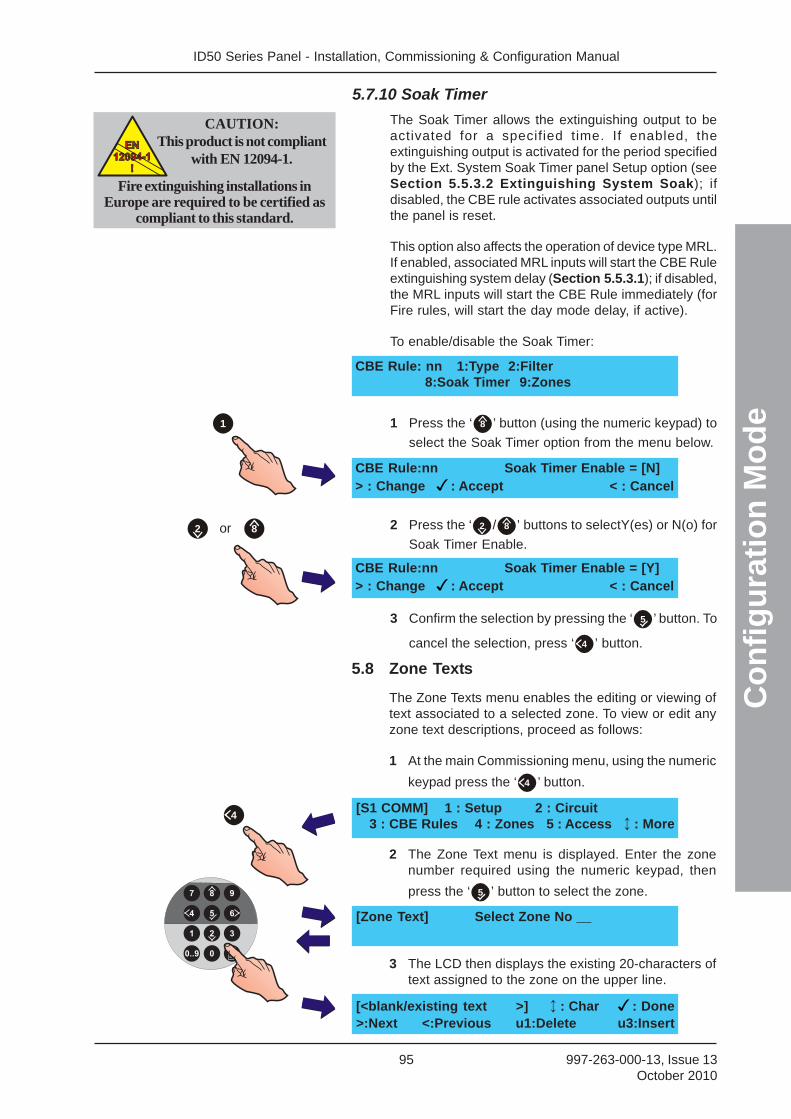
ID50 Series Panel - Installation, Commissioning & Configuration Manual
Co
nfi
gu
rati
on
Mo
de
95 997-263-000-13, Issue 13October 2010
5.7.10 Soak Timer
The Soak Timer allows the extinguishing output to beactivated for a specified time. If enabled, theextinguishing output is activated for the period specifiedby the Ext. System Soak Timer panel Setup option (seeSection 5.5.3.2 Extinguishing System Soak); ifdisabled, the CBE rule activates associated outputs untilthe panel is reset.
This option also affects the operation of device type MRL.If enabled, associated MRL inputs will start the CBE Ruleextinguishing system delay (Section 5.5.3.1); if disabled,the MRL inputs will start the CBE Rule immediately (forFire rules, will start the day mode delay, if active).
To enable/disable the Soak Timer:
1 Press the ‘ 8 ’ button (using the numeric keypad) to
select the Soak Timer option from the menu below.
2 Press the ‘ 2 / 8 ’ buttons to selectY(es) or N(o) for
Soak Timer Enable.
3 Confirm the selection by pressing the ‘ 5 ’ button. To
cancel the selection, press ‘ 4 ’ button.
5.8 Zone Texts
The Zone Texts menu enables the editing or viewing oftext associated to a selected zone. To view or edit anyzone text descriptions, proceed as follows:
1 At the main Commissioning menu, using the numeric
keypad press the ‘ 4 ’ button.
2 The Zone Text menu is displayed. Enter the zonenumber required using the numeric keypad, then
press the ‘ 5 ’ button to select the zone.
3 The LCD then displays the existing 20-characters oftext assigned to the zone on the upper line.
[S1 COMM] 1 : Setup 2 : Circuit3 : CBE Rules 4 : Zones 5 : Access : More
[<blank/existing text >] : Char : Done>:Next <:Previous u1:Delete u3:Insert
[Zone Text] Select Zone No __
4
CBE Rule:nn Soak Timer Enable = [N]> : Change : Accept < : Cancel
CBE Rule: nn 1:Type 2:Filter8:Soak Timer 9:Zones
CBE Rule:nn Soak Timer Enable = [Y]> : Change : Accept < : Cancel
1
or2 8
CAUTION:This product is not compliant
with EN 12094-1.EN
12094-1
!
EN
12094-1
!
Fire extinguishing installations inEurope are required to be certified as
compliant to this standard.
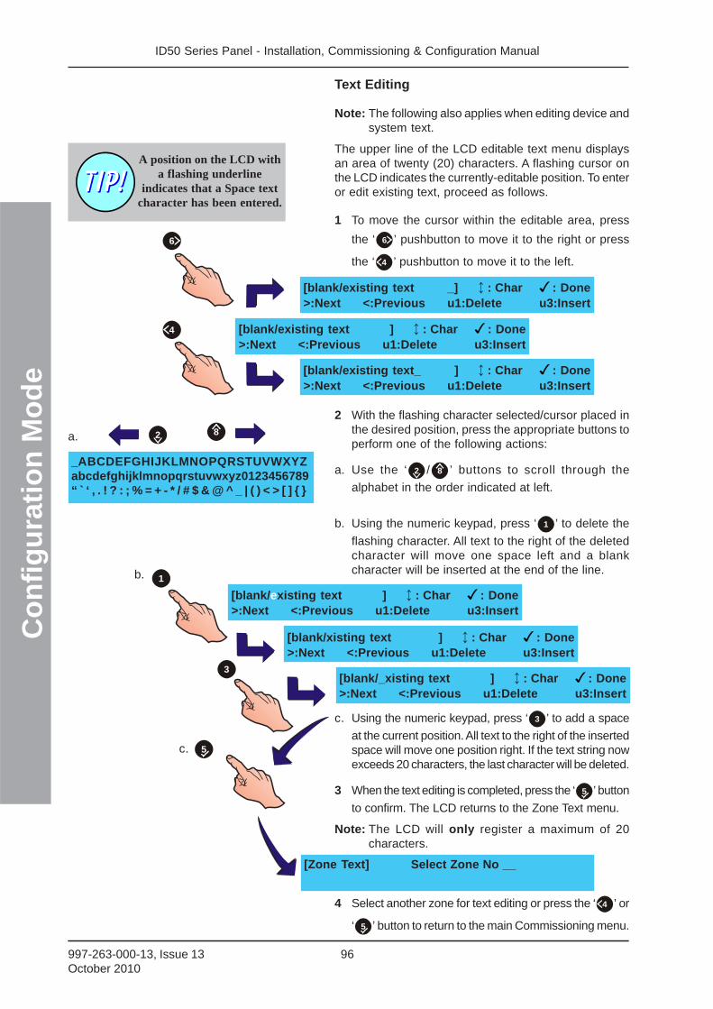
ID50 Series Panel - Installation, Commissioning & Configuration ManualC
on
fig
ura
tio
n M
od
e
96997-263-000-13, Issue 13October 2010
Text Editing
Note: The following also applies when editing device andsystem text.
The upper line of the LCD editable text menu displaysan area of twenty (20) characters. A flashing cursor onthe LCD indicates the currently-editable position. To enteror edit existing text, proceed as follows.
1 To move the cursor within the editable area, press
the ‘ 6 ’ pushbutton to move it to the right or press
the ‘ 4 ’ pushbutton to move it to the left.
2 With the flashing character selected/cursor placed inthe desired position, press the appropriate buttons toperform one of the following actions:
a. Use the ‘ 2 / 8 ’ buttons to scroll through the
alphabet in the order indicated at left.
b. Using the numeric keypad, press ‘ 1 ’ to delete the
flashing character. All text to the right of the deletedcharacter will move one space left and a blankcharacter will be inserted at the end of the line.
c. Using the numeric keypad, press ‘ 3 ’ to add a space
at the current position. All text to the right of the insertedspace will move one position right. If the text string nowexceeds 20 characters, the last character will be deleted.
3 When the text editing is completed, press the ‘ 5 ’ button
to confirm. The LCD returns to the Zone Text menu.
Note: The LCD will only register a maximum of 20characters.
4 Select another zone for text editing or press the ‘ 4 ’ or
‘ 5 ’ button to return to the main Commissioning menu.
[blank/existing text ] : Char : Done>:Next <:Previous u1:Delete u3:Insert
[blank/xisting text ] : Char : Done>:Next <:Previous u1:Delete u3:Insert
[blank/_xisting text ] : Char : Done>:Next <:Previous u1:Delete u3:Insert
_ABCDEFGHIJKLMNOPQRSTUVWXYZabcdefghijklmnopqrstuvwxyz0123456789“ ` ‘ , . ! ? : ; % = + - * / # $ & @ ^ _ | ( ) < > [ ] { }
a.
b.
c.
2 8
1
3
5
[blank/existing text _] : Char : Done>:Next <:Previous u1:Delete u3:Insert
[blank/existing text ] : Char : Done>:Next <:Previous u1:Delete u3:Insert
[blank/existing text_ ] : Char : Done>:Next <:Previous u1:Delete u3:Insert
A position on the LCD witha flashing underline
indicates that a Space textcharacter has been entered.
6
4
[Zone Text] Select Zone No __
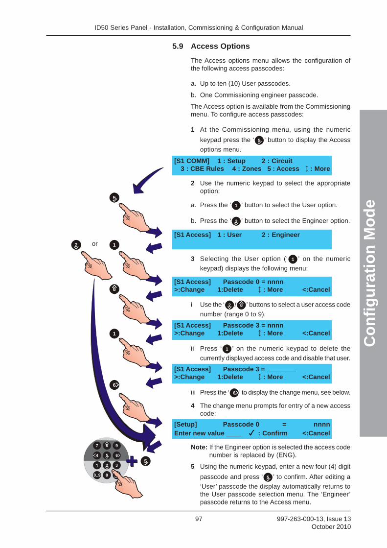
ID50 Series Panel - Installation, Commissioning & Configuration Manual
Co
nfi
gu
rati
on
Mo
de
97 997-263-000-13, Issue 13October 2010
5.9 Access Options
The Access options menu allows the configuration ofthe following access passcodes:
a. Up to ten (10) User passcodes.
b. One Commissioning engineer passcode.
The Access option is available from the Commissioningmenu. To configure access passcodes:
1 At the Commissioning menu, using the numeric
keypad press the ‘ 5 ’ button to display the Access
options menu.
2 Use the numeric keypad to select the appropriateoption:
a. Press the ‘ 1 ’ button to select the User option.
b. Press the ‘ 2 ’ button to select the Engineer option.
3 Selecting the User option (‘ 1 ’ on the numeric
keypad) displays the following menu:
i Use the ‘ 2 / 8 ’ buttons to select a user access code
number (range 0 to 9).
ii Press ‘ 1 ’ on the numeric keypad to delete the
currently displayed access code and disable that user.
iii Press the ‘ 6 ’ to display the change menu, see below.
4 The change menu prompts for entry of a new accesscode:
Note: If the Engineer option is selected the access codenumber is replaced by (ENG).
5 Using the numeric keypad, enter a new four (4) digit
passcode and press ‘ 5 ’ to confirm. After editing a
‘User’ passcode the display automatically returns tothe User passcode selection menu. The ‘Engineer’passcode returns to the Access menu.
[S1 COMM] 1 : Setup 2 : Circuit3 : CBE Rules 4 : Zones 5 : Access : More
[S1 Access] 1 : User 2 : Engineer
[S1 Access] Passcode 0 = nnnn>:Change 1:Delete : More <:Cancel
[S1 Access] Passcode 3 = nnnn>:Change 1:Delete : More <:Cancel
[S1 Access] Passcode 3 = ________>:Change 1:Delete : More <:Cancel
[Setup] Passcode 0 = nnnnEnter new value ____ : Confirm <:Cancel
or
5
1
8
1
2
6
5
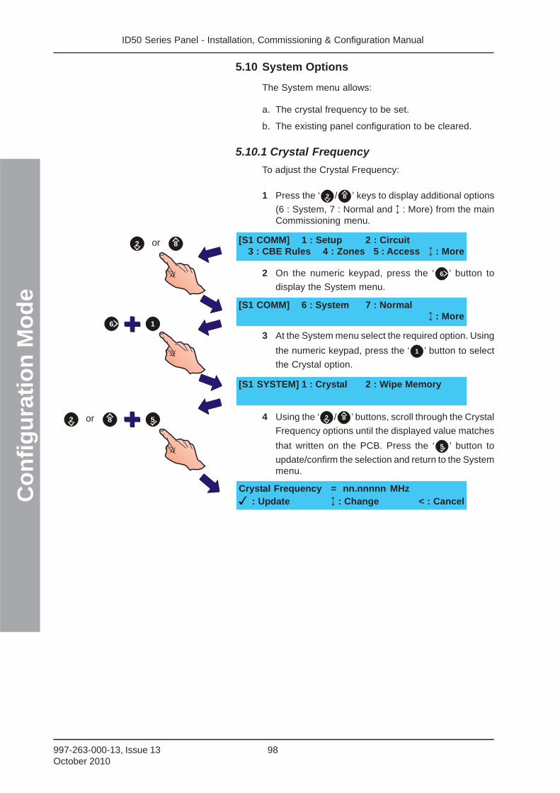
ID50 Series Panel - Installation, Commissioning & Configuration ManualC
on
fig
ura
tio
n M
od
e
98997-263-000-13, Issue 13October 2010
5.10 System Options
The System menu allows:
a. The crystal frequency to be set.
b. The existing panel configuration to be cleared.
5.10.1 Crystal Frequency
To adjust the Crystal Frequency:
1 Press the ‘ 2 / 8 ’ keys to display additional options
(6 : System, 7 : Normal and : More) from the mainCommissioning menu.
2 On the numeric keypad, press the ‘ 6 ’ button to
display the System menu.
3 At the System menu select the required option. Using
the numeric keypad, press the ‘ 1 ’ button to select
the Crystal option.
4 Using the ‘ 2 / 8 ’ buttons, scroll through the Crystal
Frequency options until the displayed value matches
that written on the PCB. Press the ‘ 5 ’ button to
update/confirm the selection and return to the Systemmenu.
[S1 COMM] 1 : Setup 2 : Circuit3 : CBE Rules 4 : Zones 5 : Access : More
[S1 COMM] 6 : System 7 : Normal : More
[S1 SYSTEM] 1 : Crystal 2 : Wipe Memory
Crystal Frequency = nn.nnnnn MHz : Update : Change < : Cancel
or 82
5or 82
16
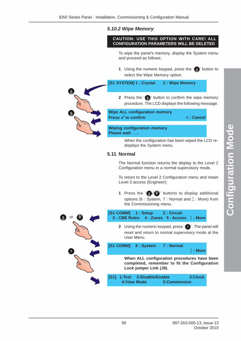
ID50 Series Panel - Installation, Commissioning & Configuration Manual
Co
nfi
gu
rati
on
Mo
de
99 997-263-000-13, Issue 13October 2010
5.10.2 Wipe Memory
CAUTION: USE THIS OPTION WITH CARE! ALLCONFIGURATION PARAMETERS WILL BE DELETED!
To wipe the panel’s memory, display the System menuand proceed as follows:
1 Using the numeric keypad, press the ‘ 2 ’ button to
select the Wipe Memory option.
2 Press the ‘ 5 ’ button to confirm the wipe memory
procedure. The LCD displays the following message.
When the configuration has been wiped the LCD re-displays the System menu.
5.11 Normal
The Normal function returns the display to the Level 2Configuration menu in a normal supervisory mode.
To return to the Level 2 Configuration menu and retainLevel 3 access (Engineer):
1 Press the ‘ 2 / 8 ’ buttons to display additional
options (6 : System, 7 : Normal and : More) fromthe Commissioning menu.
2 Using the numeric keypad, press ‘ 7 ’. The panel will
reset and return to normal supervisory mode at theUser Menu.
When ALL configuration procedures have beencompleted, remember to fit the ConfigurationLock jumper Link (J9).
[S1 COMM] 1 : Setup 2 : Circuit3 : CBE Rules 4 : Zones 5 : Access : More
[S1 COMM] 6 : System 7 : Normal : More
[S1] 1:Test 2:Disable/Enable 3:Clock4:View Mode 5:Commission
or 82
7
[S1 SYSTEM] 1 : Crystal 2 : Wipe Memory
Wipe ALL configuration memoryPress to confirm < : Cancel
Wiping configuration memoryPlease wait . . .
5
2

ID50 Series Panel - Installation, Commissioning & Configuration Manual
Ap
pen
dix
1 -
Sp
ecif
icat
ion
s
A1 - 1 997-263-000-13, Issue 13October 2010
Appendix 1 - Specification
ID50 Series Panel
General:
This fire control panel is designed to comply with therequirements of EN 54 Part 2/4. See Section 1.4 CE Markingfor further details. In addition to the basic requirements ofEN 54-2, the panel may be configured to conform with optionalrequirements as described in Section 1.5 EN 54 Functions.
Mechanical:
Construction: Sheet steel enclosure carries alldisplays and controls under a steelsheet cover.
Dimensions (mm): 365(h) x 380(w) x 110(d)
Approx Weight
Back Box: 6kg (no batteries)
Environmental:
Climatic classification: 3K5, (IEC 721-2-3)
Operating temperature: -5oC to +45oC,(recommended +5oC to 35oC)
Humidity: 5% to 95% R.H.
Height above sea level: Maximum, 2000m
Panel sealing: IP 30, (EN 60529)
Vibration: EN 60068-2-6, 10-150Hz at0.981ms-2 (Meets the requirementsof EN 54-2/4)
EMC: Emissions: EN 61000-6-3
Immunity: EN 50130-4
Safety: EN 60950
Displays and Indications:
Alphanumeric display: 2 line x 40 character, backlit LCD.
LED Status Indicators: FIRE, DISABLEMENT, TEST,FAULT, DELAYS ACTIVE, FIREOUTPUT: FAULT/DISABLED, FIREOUTPUT ACTIVE, PLANT ALARM,POWER, FAULT, POWER SUPPLYFAULT, EARTH FAULT, SYSTEMFAULT, SOUNDER: FAULT/DISABLED, PRE-ALARM, FIRECONTROL O/P: FAULT/DISABLED.
Zone Indicators: Individual FIRE and Fault/Disable/Test indicators for 16 zones.
ID50 Series Panel - Installation, Commissioning & Configuration ManualA
pp
end
ix 1
- S
pec
ific
atio
ns
A1 - 2997-263-000-13, Issue 13October 2010
Controls:
Dedicated flushpushbuttons are providedfor the following functions: MUTE BUZZER, EXTEND DELAY,
END DELAY/EVACUATE, SILENCE/RESOUND, RESET,
Additional pushbuttons forconfiguration and selection
of software functions: 2 4 6 8 KEYS
5 KEY
0..9 KEY
KEY
10 BUTTON NUMERIC KEYPAD
System Capacity:
Number of loops: 1
Number of zones: 32 (16 Fire + 16 Plant Alarm)
Devices per loop: CLIP or OPAL* protocol: 99 sensors+ 99 modules or 99 sensors +combination of up to 99 modules/sounders within strict limits.
External Connections:
Cable entry: 16 x 20mm knock-outs in top of cabinet.
Terminals: All external connections madethrough screw terminals, each ofwhich will accept cable sizesbetween 0.5mm2 and 2.5mm2.
Electrical:
Classification: Installation Class 1, (panel must beearthed).
Power Supply and Charger
Operating Voltage: 230V 50Hz AC
Voltage Tolerance: +10% -15%
Base card input: 18V AC from integral mainstransformer.
Battery Charger output: 27.1V nom. @ 20ºC (temperaturecompensated and current limited).
AUX DC Output Voltage: Maximum output voltage = 29V1
Minimum output voltage = 17.1V 2.
EN54 Battery Wiring Test Impedance: 0.4 Ohm
EN54-4 PSU Loadings:
Imax(a)
= 350mA @26.0Vdc
Imax(b)
= 2.1A @26.0Vdc
1 At maximum AC mains voltage (230V +10%)2 At V
IN = 196 VAC and with panel fully loaded.
* The loop can be configured to pollCLIP devices or, when OPAL protocolis enabled, a mixture of OPAL and CLIPdevices, providing no more than 40CLIP devices are configured.
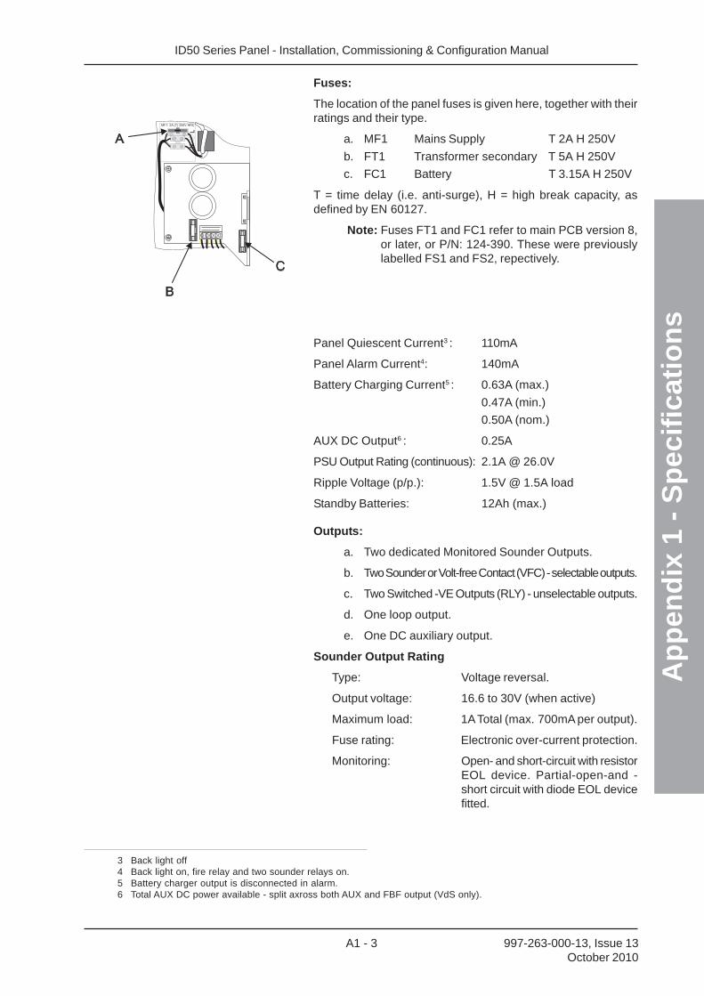
ID50 Series Panel - Installation, Commissioning & Configuration Manual
Ap
pen
dix
1 -
Sp
ecif
icat
ion
s
A1 - 3 997-263-000-13, Issue 13October 2010
Fuses:
The location of the panel fuses is given here, together with theirratings and their type.
a. MF1 Mains Supply T 2A H 250V
b. FT1 Transformer secondary T 5A H 250V
c. FC1 Battery T 3.15A H 250V
T = time delay (i.e. anti-surge), H = high break capacity, asdefined by EN 60127.
Note: Fuses FT1 and FC1 refer to main PCB version 8,or later, or P/N: 124-390. These were previouslylabelled FS1 and FS2, repectively.
Panel Quiescent Current3 : 110mA
Panel Alarm Current4: 140mA
Battery Charging Current5 : 0.63A (max.)
0.47A (min.)
0.50A (nom.)
AUX DC Output6 : 0.25A
PSU Output Rating (continuous): 2.1A @ 26.0V
Ripple Voltage (p/p.): 1.5V @ 1.5A load
Standby Batteries: 12Ah (max.)
Outputs:
a. Two dedicated Monitored Sounder Outputs.
b. Two Sounder or Volt-free Contact (VFC) - selectable outputs.
c. Two Switched -VE Outputs (RLY) - unselectable outputs.
d. One loop output.
e. One DC auxiliary output.
Sounder Output Rating
Type: Voltage reversal.
Output voltage: 16.6 to 30V (when active)
Maximum load: 1A Total (max. 700mA per output).
Fuse rating: Electronic over-current protection.
Monitoring: Open- and short-circuit with resistorEOL device. Partial-open-and -short circuit with diode EOL devicefitted.
3 Back light off4 Back light on, fire relay and two sounder relays on.5 Battery charger output is disconnected in alarm.6 Total AUX DC power available - split axross both AUX and FBF output (VdS only).
ID50 Series Panel - Installation, Commissioning & Configuration ManualA
pp
end
ix 1
- S
pec
ific
atio
ns
A1 - 4997-263-000-13, Issue 13October 2010
Volt-free Contact (VFC) Output Rating
Type: Single-pole change-over
Maximum load: Contacts rated 30V 1A
Fuse rating: Not applicable
Switched -VE Output Rating
Output voltage: 16 to 30V
Maximum load: 83mA (total for both outputs)
Loop Output
Output voltage: 22.5 to 26.4V.
Maximum load1: 0.5A peak current*
Max. loop impedance**: 20 ohms (-ve cable only, withduplicate address detection) or 40ohms (-ve cable only, withoutduplicate address detection).
Max. loop capacitance: 0.5μF
1 The panel (software version 5.04, or later) is compatible withthe Loop Booster Module (LBM). The LBM providesadditional power to the loop for output modules during panelalarm conditions. Refer to the instructions (997-509-000-X)provided with the LBM for a complete technical specification.
Up to 198 loop devices (up to 99 sensors and 99 modules) maybe fitted to the analogue loop.
The communication with devices on the loop can use either theNotifier ‘CLIP’ or OPAL polling protocol. Refer to HardwareRecommendations for a list of compatible devices and loadinglimitations.
DC Auxiliary Rating
Output voltage range: 17.1 to 30V
Maximum load: 250mA
Quiescent: 150mA*
Alarm: 0.25A*Cables should be capable ofcarrying a minimum 1A.
Fuse rating: Not applicable
Note: It is recommended that the auxiliary outputshould not be used in the quiescent state otherthan to provide a supply to drive ancillary devices’power indicators.
RS485 Serial Port (Optional)
Isolation: Functional at 30V.
Baud rate: 1200 Baud.
Connector: Terminal block on RS485 InterfaceModule PCB.
Maximum cable length: 1200metres (minimum of 1.5mm2
screened cable recommended)
* Total system load is limited by thetransformer output 1. The Notifier Loopand Battery Calculator Support Tool,should be used to ensure that the systemis NOT overloaded.
** Use the following loop driver sourceimpedance values for panel calculation
purposes: 3.8R at 22.5Vdc

ID50 Series Panel - Installation, Commissioning & Configuration Manual
Ap
pen
dix
1 -
Sp
ecif
icat
ion
s
A1 - 5 997-263-000-13, Issue 13October 2010
Configuring
Configuration methods: Front panel keypad.
Offline using PC Offline SupportTool program.
Configuration access: Keypad access is passcode-protected (user-definable) for allconfiguration.
Refer to Sections 4 & 5 of thismanual, and to 997-264-000-X ID50Series Panel Operating Manual,Section 4 for further information.
Default Configuration Passcodes:
Level 2 Passcode 2 2 2 2
Level 3 Passcode 3 3 3 3
Repeaters/Mimics
Refer to 997-411-000-X, IDR-2A, 2P & 6A Repeaters UserManual and 997-412-000-X, IDR Mimic Installation andCommissioning Manual for the specification.
Recommended Cables
All cables connected to the fire alarm control panel must be fire resistant cables. Shielded cable must beused for signalling loops and sounder circuits. The drain earth wire should be connected to a suitable earthbonding point at both ends of the cable. Keep the earth connections as short as possible.
In the UK, the British Standard BS5839 Part 1 : 2002 Code of Practice for system design, installation,commissioning and maintenance states the requirements for standard and fire resisting cables in Clause26.2 section d and e:
‘d) Standard fire resisting cables should meet PH30 classification when tested in accordance with EN50200 andmaintain circuit integrity if exposed to the following test:
- A sample of the cable is simultaneously exposed to flame at a temperature of 830°C – 0+40°C and mechanical shockfor 15 minutes, followed by simultaneous exposure to water spray and mechanical shock for a further 15 minutes.
e) Enhanced fire resisting cables should meet the PH120 classification when tested in accordance with EN50200and maintain circuit integrity if exposed to the following test:
- A sample of the cable is simultaneously exposed to flame at a temperature of 930°C – 0+40°C and mechanical shockfor 60 minutes, followed by simultaneous exposure to water spray and mechanical shock for a further 60 minutes.’
Loop cable
A loop cable carries data therefore its selection is important. Note the following:
- In countries where the European EMC directive is in force, only EMC Compliant cables are to be used.
- The loop cable usage must not exceed 2 km. This includes the cable used on main loop and spur circuits.
- Single pair cables must be used. It is NOT permissible to run mixed loops or outgoing and return pairs in a multi-core cable due to inadequate separation and possible electrical interference problems.
- Each core of the loop cable must be a minimum 1.5mm2 cross sectional area.
- The cable screen must be capable of being earthed at each system device – only one end of each cable screenmust be earthed.
- Red is the preferred cover sheath for fire applications
- The specified loop circuit cables are also suitable for wiring alarm, auxiliary relay and input/output lines.
Mains supply cable
The mains supply cable must be a standard fire resisting type and should meet PH30 classification, such as any ofthe standard and enhanced cables listed below. Examples of enhanced and standard cables are:
Enhanced:
- Mineral insulated cable (MICC) to BS6207: Part 1
- Draka FIRETUF Plus Enhanced FTPLUS2EHL5RD.
ID50 Series Panel - Installation, Commissioning & Configuration ManualA
pp
end
ix 1
- S
pec
ific
atio
ns
A1 - 6997-263-000-13, Issue 13October 2010
Standard:
- Prysmian FP200 FLEX
- Prysmian FP200 GOLD
Refer to your supplier for details of other available industry standard fire resisting cables.
Listed below are fire rated cables for signalling loops and sounder circuits that met the requirements ofprevious approval standards:
1. AEI type Firetec Multicore Ref. F1C1 (1mm2) to F1C2.5 (2.5mm2) in 2 core.
2. AEI type Firetec Armoured Ref. F2C1 (1.5mm2) to F2C2.5 (2.5mm2) in 2 core.
3. AEI type Mineral Insulated Cable (all types up to 2.5mm2).
4. BICC types Mineral Insulated twin twisted conductor cables, Ref. CCM2T1RG and CCM2T1.5RG.
5. BICC type Mineral Insulated Pyrotenax (all types up to 2.5mm2)
6. CALFLEX type Calflam CWZ 2 core type up to 2.5mm2 maximum
7. Prysmian (formerly PIRELLI) type FP200 Gold 2 core type from 1mm2 to 2.5mm2
8. Draka FIRETUF (OHLS) FTZ up to 2.5mm2
9. Signal Cables for RS485 Communications Links (twisted pair)
10.12 AWG Signal 88202 Belden 9583 WPW999
11. 14 AWG Signal 88402 Belden 9581 WPW995
12.16 AWG Signal 88602 Belden 9575 WPW991
13.18 AWG Signal 88802 Belden 9574 WPW975
14.FIRETUF FDZ1000 by Draka 2 core.
15.Prysmian (formerly PIRELLI) type FP200 Gold 2 core.
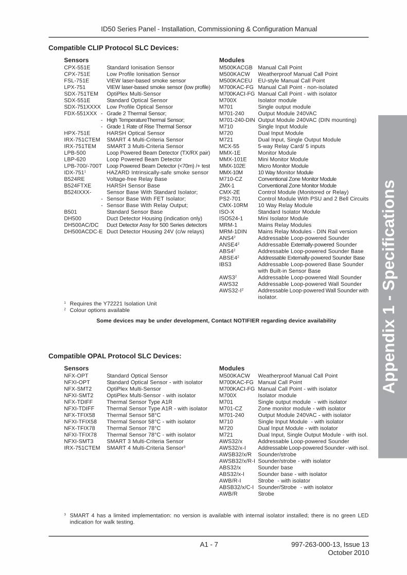
ID50 Series Panel - Installation, Commissioning & Configuration Manual
Ap
pen
dix
1 -
Sp
ecif
icat
ion
s
A1 - 7 997-263-000-13, Issue 13October 2010
Compatible CLIP Protocol SLC Devices:
Sensors ModulesCPX-551E Standard Ionisation Sensor M500KACGB Manual Call PointCPX-751E Low Profile Ionisation Sensor M500KACW Weatherproof Manual Call PointFSL-751E VIEW laser-based smoke sensor M500KACEU EU-style Manual Call PointLPX-751 VIEW laser-based smoke sensor (low profile) M700KAC-FG Manual Call Point - non-isolatedSDX-751TEM OptiPlex Multi-Sensor M700KACI-FG Manual Call Point - with isolatorSDX-551E Standard Optical Sensor M700X Isolator moduleSDX-751XXXX Low Profile Optical Sensor M701 Single output moduleFDX-551XXX - Grade 2 Thermal Sensor; M701-240 Output Module 240VAC
- High TemperatureThermal Sensor; M701-240-DIN Output Module 240VAC (DIN mounting)- Grade 1 Rate of Rise Thermal Sensor M710 Single Input Module
HPX-751E HARSH Optical Sensor M720 Dual Input ModuleIRX-751CTEM SMART 4 Multi-Criteria Sensor M721 Dual Input, Single Output ModuleIRX-751TEM SMART 3 Multi-Criteria Sensor MCX-55 5-way Relay Card/ 5 inputsLPB-500 Loop Powered Beam Detector (TX/RX pair) MMX-1E Monitor ModuleLBP-620 Loop Powered Beam Detector MMX-101E Mini Monitor ModuleLPB-700/-700T Loop Powered Beam Detector (<70m) /+ test MMX-102E Micro Monitor ModuleIDX-7511 HAZARD Intrinsically-safe smoke sensor MMX-10M 10 Way Monitor ModuleB524RE Voltage-free Relay Base M710-CZ Conventional Zone Monitor ModuleB524FTXE HARSH Sensor Base ZMX-1 Conventional Zone Monitor ModuleB524IXXX- Sensor Base With Standard Isolator; CMX-2E Control Module (Monitored or Relay)
- Sensor Base With FET Isolator; PS2-701 Control Module With PSU and 2 Bell Circuits- Sensor Base With Relay Output; CMX-10RM 10 Way Relay Module
B501 Standard Sensor Base ISO-X Standard Isolator ModuleDH500 Duct Detector Housing (indication only) ISO524-1 Mini Isolator ModuleDH500AC/DC Duct Detector Assy for 500 Series detectors MRM-1 Mains Relay ModulesDH500ACDC-E Duct Detector Housing 24V (c/w relays) MRM-1DIN Mains Relay Modules - DIN Rail version
ANS42 Addressable Loop-powered SounderANSE42 Addressable Externally-powered SounderABS42 Addressable Loop-powered Sounder BaseABSE42 Addressable Externally-powered Sounder BaseIBS3 Addressable Loop-powered Base Sounder
with Built-in Sensor BaseAWS32 Addressable Loop-powered Wall SounderAWS32 Addressable Loop-powered Wall SounderAWS32-I2 Addressable Loop-powered Wall Sounder with
isolator.1 Requires the Y72221 Isolation Unit2 Colour options available
Some devices may be under development, Contact NOTIFIER regarding device availability
Compatible OPAL Protocol SLC Devices:
Sensors ModulesNFX-OPT Standard Optical Sensor M500KACW Weatherproof Manual Call PointNFXI-OPT Standard Optical Sensor - with isolator M700KAC-FG Manual Call PointNFX-SMT2 OptiPlex Multi-Sensor M700KACI-FG Manual Call Point - with isolatorNFXI-SMT2 OptiPlex Multi-Sensor - with isolator M700X Isolator moduleNFX-TDIFF Thermal Sensor Type A1R M701 Single output module - with isolatorNFXI-TDIFF Thermal Sensor Type A1R - with isolator M701-CZ Zone monitor module - with isolatorNFX-TFIX58 Thermal Sensor 58°C M701-240 Output Module 240VAC - with isolatorNFXI-TFIX58 Thermal Sensor 58°C - with isolator M710 Single Input Module - with isolatorNFX-TFIX78 Thermal Sensor 78°C M720 Dual Input Module - with isolatorNFXI-TFIX78 Thermal Sensor 78°C - with isolator M721 Dual Input, Single Output Module - with isol.NFXI-SMT3 SMART 3 Multi-Criteria Sensor AWS32/x Addressable Loop-powered SounderIRX-751CTEM SMART 4 Multi-Criteria Sensor3 AWS32/x-I Addressable Loop-powered Sounder - with isol.
AWSB32/x/R Sounder/strobeAWSB32/x/R-I Sounder/strobe - with isolatorABS32/x Sounder baseABS32/x-I Sounder base - with isolatorAWB/R-I Strobe - with isolatorABSB32/x/C-I Sounder/Strobe - with isolatorAWB/R Strobe
3 SMART 4 has a limited implementation: no version is available with internal isolator installed; there is no green LEDindication for walk testing.
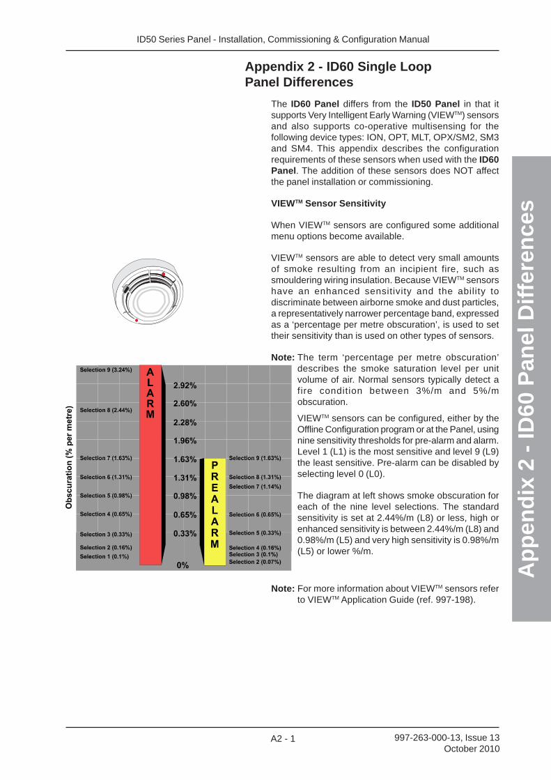
ID50 Series Panel - Installation, Commissioning & Configuration Manual
Ap
pen
dix
2 -
ID60
Pan
el D
iffe
ren
ces
A2 - 1 997-263-000-13, Issue 13October 2010
Appendix 2 - ID60 Single LoopPanel Differences
The ID60 Panel differs from the ID50 Panel in that itsupports Very Intelligent Early Warning (VIEWTM) sensorsand also supports co-operative multisensing for thefollowing device types: ION, OPT, MLT, OPX/SM2, SM3and SM4. This appendix describes the configurationrequirements of these sensors when used with the ID60Panel. The addition of these sensors does NOT affectthe panel installation or commissioning.
VIEWTM Sensor Sensitivity
When VIEWTM sensors are configured some additionalmenu options become available.
VIEWTM sensors are able to detect very small amountsof smoke resulting from an incipient fire, such assmouldering wiring insulation. Because VIEWTM sensorshave an enhanced sensitivity and the ability todiscriminate between airborne smoke and dust particles,a representatively narrower percentage band, expressedas a ‘percentage per metre obscuration’, is used to settheir sensitivity than is used on other types of sensors.
Note: The term ‘percentage per metre obscuration’describes the smoke saturation level per unitvolume of air. Normal sensors typically detect afire condition between 3%/m and 5%/mobscuration.
VIEWTM sensors can be configured, either by theOffline Configuration program or at the Panel, usingnine sensitivity thresholds for pre-alarm and alarm.Level 1 (L1) is the most sensitive and level 9 (L9)the least sensitive. Pre-alarm can be disabled byselecting level 0 (L0).
The diagram at left shows smoke obscuration foreach of the nine level selections. The standardsensitivity is set at 2.44%/m (L8) or less, high orenhanced sensitivity is between 2.44%/m (L8) and0.98%/m (L5) and very high sensitivity is 0.98%/m(L5) or lower %/m.
Note: For more information about VIEWTM sensors referto VIEWTM Application Guide (ref. 997-198).
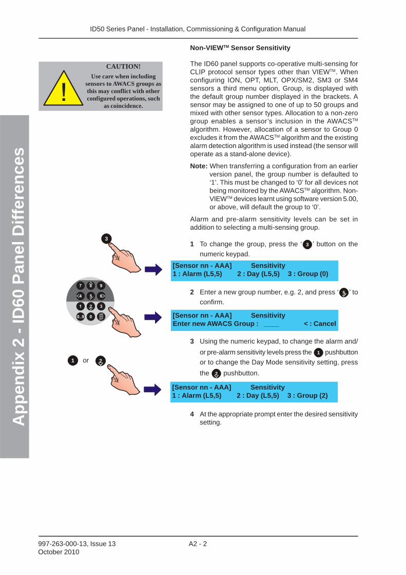
ID50 Series Panel - Installation, Commissioning & Configuration ManualA
pp
end
ix 2
- ID
60 P
anel
Dif
fere
nce
s
A2 - 2997-263-000-13, Issue 13October 2010
1
Non-VIEWTM Sensor Sensitivity
The ID60 panel supports co-operative multi-sensing forCLIP protocol sensor types other than VIEWTM. Whenconfiguring ION, OPT, MLT, OPX/SM2, SM3 or SM4sensors a third menu option, Group, is displayed withthe default group number displayed in the brackets. Asensor may be assigned to one of up to 50 groups andmixed with other sensor types. Allocation to a non-zerogroup enables a sensor’s inclusion in the AWACSTM
algorithm. However, allocation of a sensor to Group 0excludes it from the AWACSTM algorithm and the existingalarm detection algorithm is used instead (the sensor willoperate as a stand-alone device).
Note: When transferring a configuration from an earlierversion panel, the group number is defaulted to‘1’. This must be changed to ‘0’ for all devices notbeing monitored by the AWACSTM algorithm. Non-VIEWTM devices learnt using software version 5.00,or above, will default the group to ‘0’.
Alarm and pre-alarm sensitivity levels can be set inaddition to selecting a multi-sensing group.
1 To change the group, press the ‘ 3 ’ button on the
numeric keypad.
2 Enter a new group number, e.g. 2, and press ‘ 5 ’ to
confirm.
3 Using the numeric keypad, to change the alarm and/
or pre-alarm sensitivity levels press the 1 pushbutton
or to change the Day Mode sensitivity setting, press
the 2 pushbutton.
4 At the appropriate prompt enter the desired sensitivitysetting.
3
[Sensor nn - AAA] SensitivityEnter new AWACS Group : ____ < : Cancel
[Sensor nn - AAA] Sensitivity1 : Alarm (L5,5) 2 : Day (L5,5) 3 : Group (0)
[Sensor nn - AAA] Sensitivity1 : Alarm (L5,5) 2 : Day (L5,5) 3 : Group (2)
or 2
CAUTION!
Use care when includingsensors to AWACS groups asthis may conflict with otherconfigured operations, such
as coincidence.
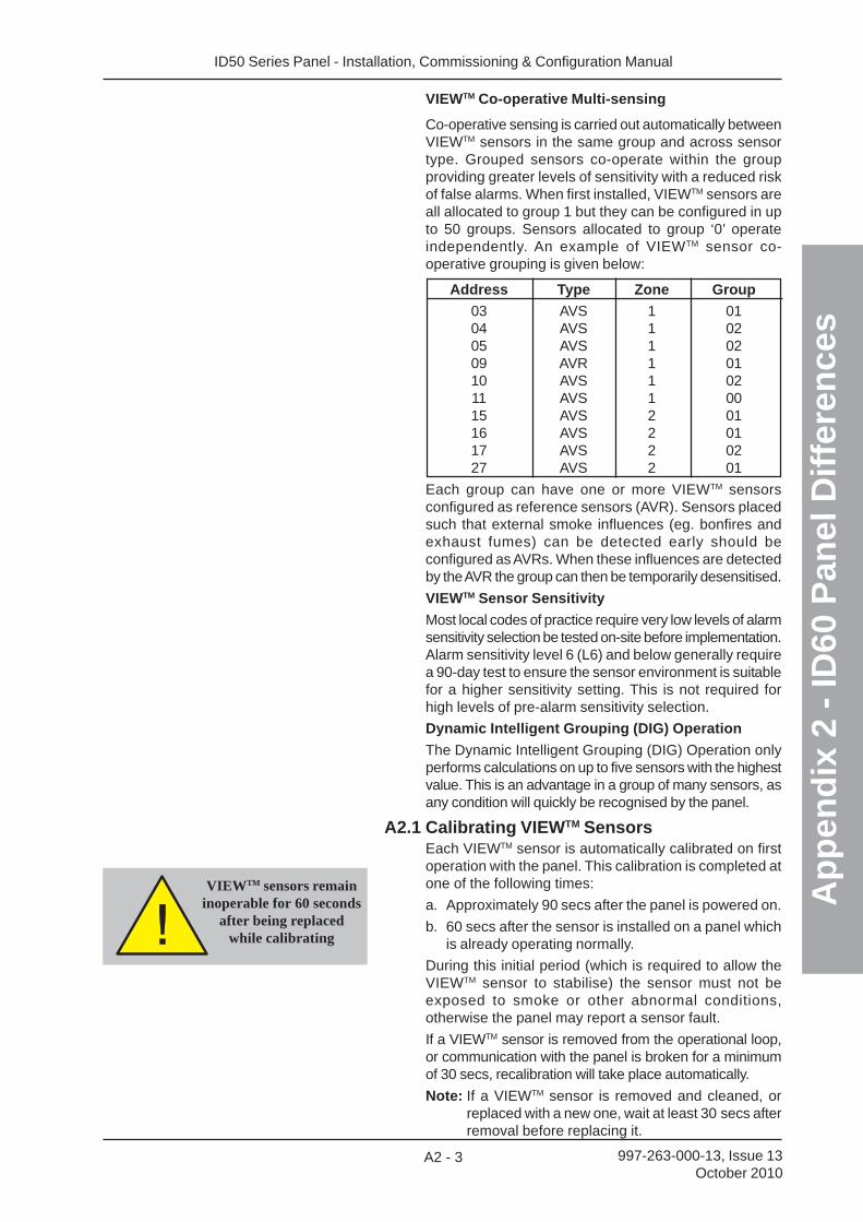
ID50 Series Panel - Installation, Commissioning & Configuration Manual
Ap
pen
dix
2 -
ID60
Pan
el D
iffe
ren
ces
A2 - 3 997-263-000-13, Issue 13October 2010
VIEWTM sensors remaininoperable for 60 seconds
after being replacedwhile calibrating
VIEWTM Co-operative Multi-sensing
Co-operative sensing is carried out automatically betweenVIEWTM sensors in the same group and across sensortype. Grouped sensors co-operate within the groupproviding greater levels of sensitivity with a reduced riskof false alarms. When first installed, VIEWTM sensors areall allocated to group 1 but they can be configured in upto 50 groups. Sensors allocated to group ‘0’ operateindependently. An example of VIEWTM sensor co-operative grouping is given below:
Address Type Zone Group
03 AVS 1 0104 AVS 1 0205 AVS 1 0209 AVR 1 0110 AVS 1 0211 AVS 1 0015 AVS 2 0116 AVS 2 0117 AVS 2 0227 AVS 2 01
Each group can have one or more VIEWTM sensorsconfigured as reference sensors (AVR). Sensors placedsuch that external smoke influences (eg. bonfires andexhaust fumes) can be detected early should beconfigured as AVRs. When these influences are detectedby the AVR the group can then be temporarily desensitised.
VIEWTM Sensor Sensitivity
Most local codes of practice require very low levels of alarmsensitivity selection be tested on-site before implementation.Alarm sensitivity level 6 (L6) and below generally requirea 90-day test to ensure the sensor environment is suitablefor a higher sensitivity setting. This is not required forhigh levels of pre-alarm sensitivity selection.
Dynamic Intelligent Grouping (DIG) Operation
The Dynamic Intelligent Grouping (DIG) Operation onlyperforms calculations on up to five sensors with the highestvalue. This is an advantage in a group of many sensors, asany condition will quickly be recognised by the panel.
A2.1 Calibrating VIEWTM SensorsEach VIEWTM sensor is automatically calibrated on firstoperation with the panel. This calibration is completed atone of the following times:
a. Approximately 90 secs after the panel is powered on.
b. 60 secs after the sensor is installed on a panel whichis already operating normally.
During this initial period (which is required to allow theVIEWTM sensor to stabilise) the sensor must not beexposed to smoke or other abnormal conditions,otherwise the panel may report a sensor fault.
If a VIEWTM sensor is removed from the operational loop,or communication with the panel is broken for a minimumof 30 secs, recalibration will take place automatically.
Note: If a VIEWTM sensor is removed and cleaned, orreplaced with a new one, wait at least 30 secs afterremoval before replacing it.
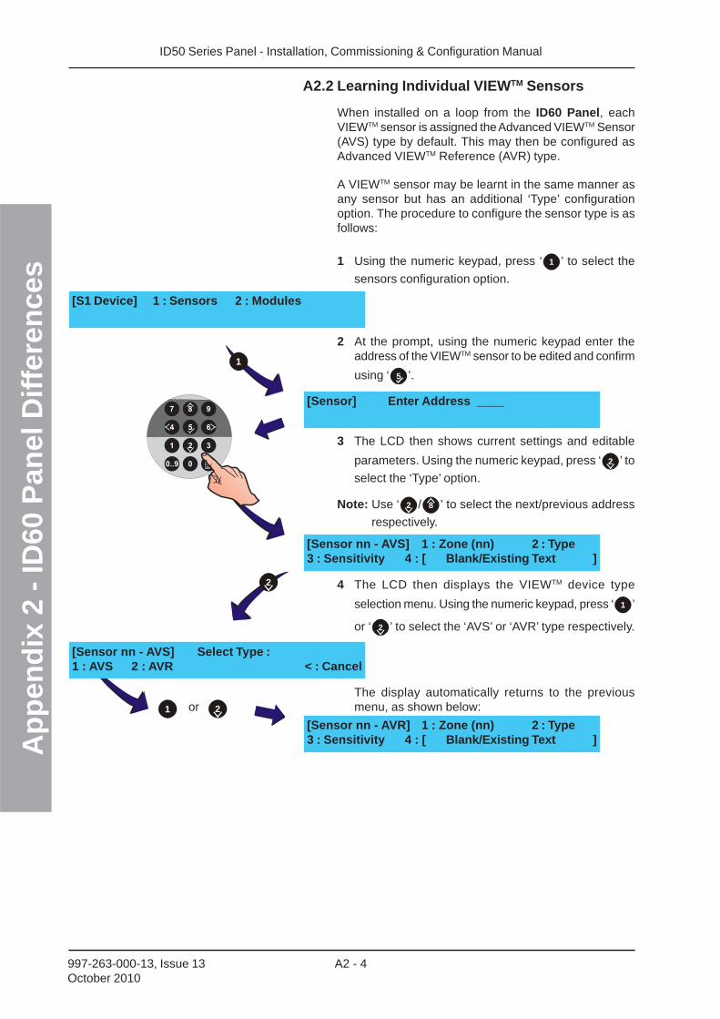
ID50 Series Panel - Installation, Commissioning & Configuration ManualA
pp
end
ix 2
- ID
60 P
anel
Dif
fere
nce
s
A2 - 4997-263-000-13, Issue 13October 2010
A2.2 Learning Individual VIEWTM Sensors
When installed on a loop from the ID60 Panel, eachVIEWTM sensor is assigned the Advanced VIEWTM Sensor(AVS) type by default. This may then be configured asAdvanced VIEWTM Reference (AVR) type.
A VIEWTM sensor may be learnt in the same manner asany sensor but has an additional ‘Type’ configurationoption. The procedure to configure the sensor type is asfollows:
1 Using the numeric keypad, press ‘ 1 ’ to select the
sensors configuration option.
2 At the prompt, using the numeric keypad enter theaddress of the VIEWTM sensor to be edited and confirm
using ‘ 5 ’.
3 The LCD then shows current settings and editable
parameters. Using the numeric keypad, press ‘ 2 ’ to
select the ‘Type’ option.
Note: Use ‘ 2 / 8 ’ to select the next/previous address
respectively.
4 The LCD then displays the VIEWTM device type
selection menu. Using the numeric keypad, press ‘ 1 ’
or ‘ 2 ’ to select the ‘AVS’ or ‘AVR’ type respectively.
The display automatically returns to the previousmenu, as shown below:
[S1 Device] 1 : Sensors 2 : Modules
[Sensor nn - AVS] 1 : Zone (nn) 2 : Type3 : Sensitivity 4 : [ Blank/Existing Text ]
[Sensor] Enter Address ____
[Sensor nn - AVR] 1 : Zone (nn) 2 : Type3 : Sensitivity 4 : [ Blank/Existing Text ]
[Sensor nn - AVS] Select Type :1 : AVS 2 : AVR < : Cancel
1
2
or1 2
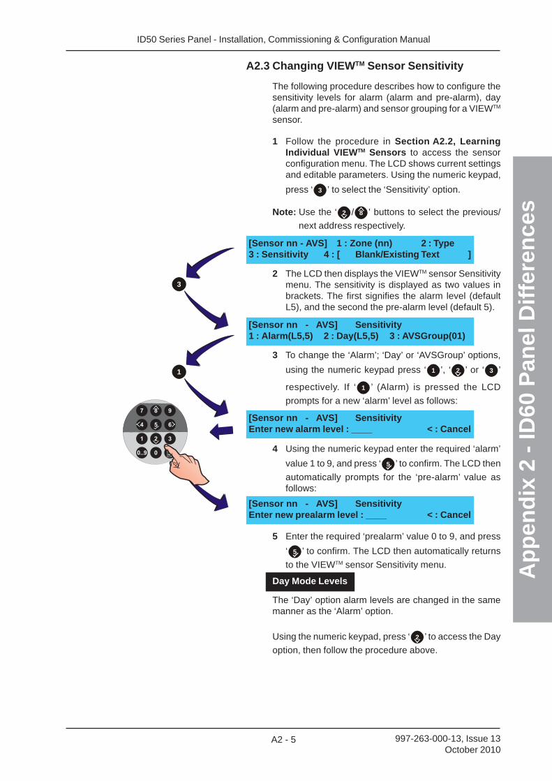
ID50 Series Panel - Installation, Commissioning & Configuration Manual
Ap
pen
dix
2 -
ID60
Pan
el D
iffe
ren
ces
A2 - 5 997-263-000-13, Issue 13October 2010
A2.3 Changing VIEWTM Sensor Sensitivity
The following procedure describes how to configure thesensitivity levels for alarm (alarm and pre-alarm), day(alarm and pre-alarm) and sensor grouping for a VIEWTM
sensor.
1 Follow the procedure in Section A2.2, LearningIndividual VIEWTM Sensors to access the sensorconfiguration menu. The LCD shows current settingsand editable parameters. Using the numeric keypad,
press ‘ 3 ’ to select the ‘Sensitivity’ option.
Note: Use the ‘ 2 / 8 ’ buttons to select the previous/
next address respectively.
2 The LCD then displays the VIEWTM sensor Sensitivitymenu. The sensitivity is displayed as two values inbrackets. The first signifies the alarm level (defaultL5), and the second the pre-alarm level (default 5).
3 To change the ‘Alarm’; ‘Day’ or ‘AVSGroup’ options,
using the numeric keypad press ‘ 1 ’, ‘ 2 ’ or ‘ 3 ’
respectively. If ‘ 1 ’ (Alarm) is pressed the LCD
prompts for a new ‘alarm’ level as follows:
4 Using the numeric keypad enter the required ‘alarm’
value 1 to 9, and press ‘ 5 ’ to confirm. The LCD then
automatically prompts for the ‘pre-alarm’ value asfollows:
5 Enter the required ‘prealarm’ value 0 to 9, and press
‘ 5 ’ to confirm. The LCD then automatically returns
to the VIEWTM sensor Sensitivity menu.
Day Mode Levels
The ‘Day’ option alarm levels are changed in the samemanner as the ‘Alarm’ option.
Using the numeric keypad, press ‘ 2 ’ to access the Day
option, then follow the procedure above.
[Sensor nn - AVS] 1 : Zone (nn) 2 : Type3 : Sensitivity 4 : [ Blank/Existing Text ]
[Sensor nn - AVS] Sensitivity1 : Alarm(L5,5) 2 : Day(L5,5) 3 : AVSGroup(01)
[Sensor nn - AVS] SensitivityEnter new alarm level : ____ < : Cancel
[Sensor nn - AVS] SensitivityEnter new prealarm level : ____ < : Cancel
1
3
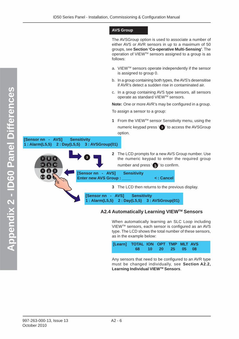
ID50 Series Panel - Installation, Commissioning & Configuration ManualA
pp
end
ix 2
- ID
60 P
anel
Dif
fere
nce
s
A2 - 6997-263-000-13, Issue 13October 2010
AVS Group
The AVSGroup option is used to associate a number ofeither AVS or AVR sensors in up to a maximum of 50groups, see Section ‘Co-operative Multi-Sensing’. Theoperation of VIEWTM sensors assigned to a group is asfollows:
a. VIEWTM sensors operate independently if the sensoris assigned to group 0.
b. In a group containing both types, the AVS’s desensitiseif AVR’s detect a sudden rise in contaminated air.
c. In a group containing AVS type sensors, all sensorsoperate as standard VIEWTM sensors.
Note: One or more AVR’s may be configured in a group.
To assign a sensor to a group:
1 From the VIEWTM sensor Sensitivity menu, using the
numeric keypad press ‘ 3 ’ to access the AVSGroup
option.
2 The LCD prompts for a new AVS Group number. Usethe numeric keypad to enter the required group
number and press ‘ 5 ’ to confirm.
3 The LCD then returns to the previous display.
A2.4 Automatically Learning VIEWTM Sensors
When automatically learning an SLC Loop includingVIEWTM sensors, each sensor is configured as an AVStype. The LCD shows the total number of these sensors,as in the example below:
Any sensors that need to be configured to an AVR typemust be changed individually, see Section A2.2,Learning Individual VIEWTM Sensors.
[Sensor nn - AVS] Sensitivity1 : Alarm(L5,5) 2 : Day(L5,5) 3 : AVSGroup(01)
[Learn] TOTAL ION OPT TMP MLT AVS68 10 20 25 05 08
[Sensor nn - AVS] SensitivityEnter new AVS Group : ____ < : Cancel
[Sensor nn - AVS] Sensitivity1 : Alarm(L5,5) 2 : Day(L5,5) 3 : AVSGroup(01)
3
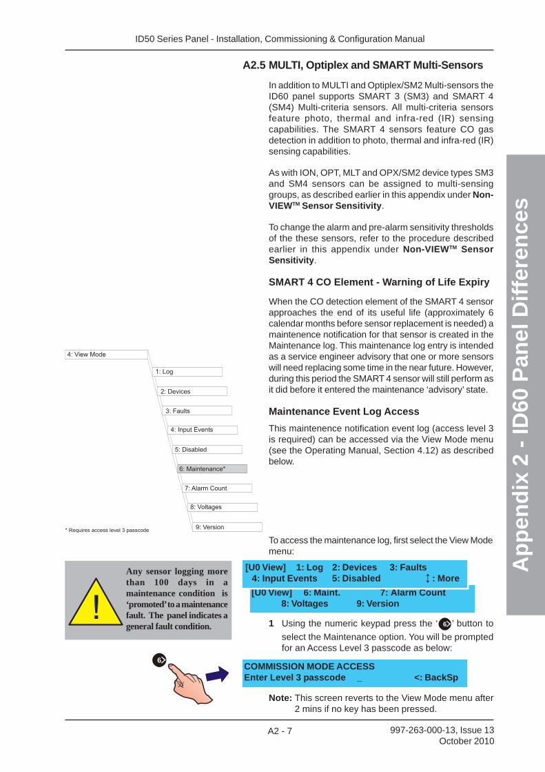
ID50 Series Panel - Installation, Commissioning & Configuration Manual
Ap
pen
dix
2 -
ID60
Pan
el D
iffe
ren
ces
A2 - 7 997-263-000-13, Issue 13October 2010
A2.5 MULTI, Optiplex and SMART Multi-Sensors
In addition to MULTI and Optiplex/SM2 Multi-sensors theID60 panel supports SMART 3 (SM3) and SMART 4(SM4) Multi-criteria sensors. All multi-criteria sensorsfeature photo, thermal and infra-red (IR) sensingcapabilities. The SMART 4 sensors feature CO gasdetection in addition to photo, thermal and infra-red (IR)sensing capabilities.
As with ION, OPT, MLT and OPX/SM2 device types SM3and SM4 sensors can be assigned to multi-sensinggroups, as described earlier in this appendix under Non-VIEWTM Sensor Sensitivity.
To change the alarm and pre-alarm sensitivity thresholdsof the these sensors, refer to the procedure describedearlier in this appendix under Non-VIEWTM SensorSensitivity.
SMART 4 CO Element - Warning of Life Expiry
When the CO detection element of the SMART 4 sensorapproaches the end of its useful life (approximately 6calendar months before sensor replacement is needed) amaintenence notification for that sensor is created in theMaintenance log. This maintenance log entry is intendedas a service engineer advisory that one or more sensorswill need replacing some time in the near future. However,during this period the SMART 4 sensor will still perform asit did before it entered the maintenance ‘advisory’ state.
Maintenance Event Log Access
This maintenence notification event log (access level 3is required) can be accessed via the View Mode menu(see the Operating Manual, Section 4.12) as describedbelow.
1 Using the numeric keypad press the ‘ 6 ’ button to
select the Maintenance option. You will be promptedfor an Access Level 3 passcode as below:
Note: This screen reverts to the View Mode menu after2 mins if no key has been pressed.
COMMISSION MODE ACCESSEnter Level 3 passcode _ <: BackSp
To access the maintenance log, first select the View Modemenu:
Any sensor logging morethan 100 days in amaintenance condition is‘promoted’ to a maintenancefault. The panel indicates ageneral fault condition.
[U0 View] 6: Maint. 7: Alarm Count8: Voltages 9: Version
[U0 View] 1: Log 2: Devices 3: Faults4: Input Events 5: Disabled : More
6
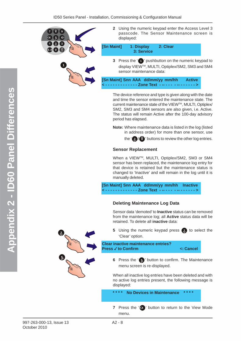
ID50 Series Panel - Installation, Commissioning & Configuration ManualA
pp
end
ix 2
- ID
60 P
anel
Dif
fere
nce
s
A2 - 8997-263-000-13, Issue 13October 2010
2 Using the numeric keypad enter the Access Level 3passcode. The Sensor Maintenance screen isdisplayed:
3 Press the ‘ 1 ’ pushbutton on the numeric keypad to
display VIEWTM, MULTI, Optiplex/SM2, SM3 and SM4sensor maintenance data:
The device reference and type is given along with the dateand time the sensor entered the maintenance state. Thecurrent maintenance state of the VIEWTM, MULTI, Optiplex/SM2, SM3 and SM4 sensors are also given, i.e. Active.The status will remain Active after the 100-day advisoryperiod has elapsed.
Note: Where maintenance data is listed in the log (listedin address order) for more than one sensor, use
the ‘ 2 / 8 ’ buttons to review the other log entries.
Sensor Replacement
When a VIEWTM, MULTI, Optiplex/SM2, SM3 or SM4sensor has been replaced, the maintenance log entry forthat device is retained but the maintenance status ischanged to ‘Inactive’ and will remain in the log until it ismanually deleted.
Deleting Maintenance Log Data
Sensor data ‘demoted’ to Inactive status can be removedfrom the maintenance log; all Active status data will beretained. To delete all inactive data:
5 Using the numeric keypad press 2 to select the
‘Clear’ option.
6 Press the ‘ 5 ’ button to confirm. The Maintenance
menu screen is re-displayed.
When all inactive log entries have been deleted and withno active log entries present, the following message isdisplayed:
7 Press the ‘ 4 ’ button to return to the View Mode
menu.
[Sn Maint] 1: Display 2: Clear3: Service
[Sn Maint] Snn AAA dd/mm/yy mm/hh Active< - - - - - - - - - - - - - Zone Text - -- - - - - -- - - - - - - >
* * * * No Devices in Maintenance * * * *
Clear inactive maintenance entries?Press to Confirm <: Cancel
[Sn Maint] Snn AAA dd/mm/yy mm/hh Inactive< - - - - - - - - - - - - - Zone Text - -- - - - - -- - - - - - - >
1
2
5
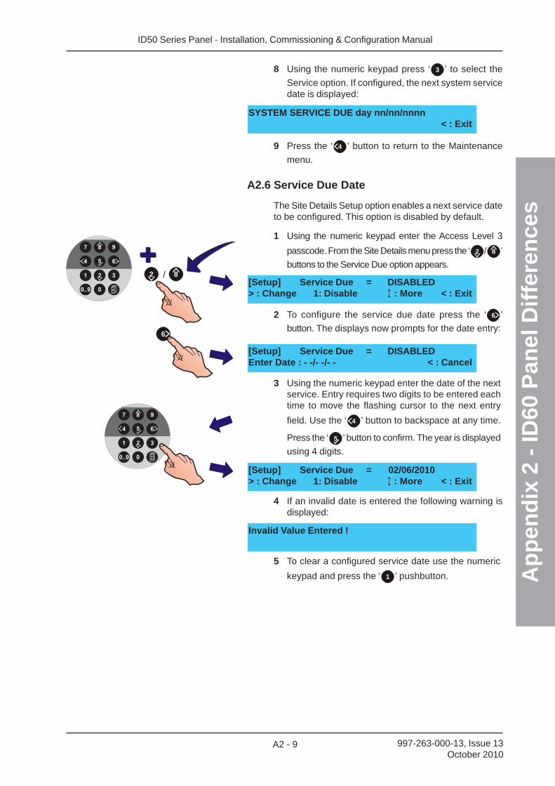
ID50 Series Panel - Installation, Commissioning & Configuration Manual
Ap
pen
dix
2 -
ID60
Pan
el D
iffe
ren
ces
A2 - 9 997-263-000-13, Issue 13October 2010
[Setup] Service Due = DISABLED> : Change 1: Disable : More < : Exit
2 To configure the service due date press the ‘ 6 ’
button. The displays now prompts for the date entry:
[Setup] Service Due = DISABLEDEnter Date : - -/- -/- - < : Cancel
3 Using the numeric keypad enter the date of the nextservice. Entry requires two digits to be entered eachtime to move the flashing cursor to the next entry
field. Use the ‘ 4 ’ button to backspace at any time.
Press the ‘ 5 ’ button to confirm. The year is displayed
using 4 digits.
Invalid Value Entered !
4 If an invalid date is entered the following warning isdisplayed:
[Setup] Service Due = 02/06/2010> : Change 1: Disable : More < : Exit
5 To clear a configured service date use the numeric
keypad and press the ‘ 1 ’ pushbutton.
6
/ 82
8 Using the numeric keypad press ‘ 3 ’ to select the
Service option. If configured, the next system servicedate is displayed:
9 Press the ‘ 4 ’ button to return to the Maintenance
menu.
A2.6 Service Due Date
The Site Details Setup option enables a next service dateto be configured. This option is disabled by default.
1 Using the numeric keypad enter the Access Level 3
passcode. From the Site Details menu press the ‘ 2 / 8 ’
buttons to the Service Due option appears.
SYSTEM SERVICE DUE day nn/nn/nnnn< : Exit
ID50 Series Panel - Installation, Commissioning & Configuration Manual
Ap
pen
dix
3 -
Fau
lt M
essa
ges
A3 - 1 997-263-000-12, Issue 12February 2010
Appendix 3
Fault Messages - Possible Causes &Remedies
Loop Wiring Installation
LOOP OPEN CIRCUIT - the loop wiring has adisconnection. Action: Check the loop wiring connectionsat the panel. If these are good and the problem persists,disconnect the loop wiring and short out the outgoing andincoming (+ve to +ve and -ve to -ve) connectors. If thefault clears this indicates the on-board loop circuitry isOK. Check wiring connection of all loop devices.
LOOP SHORT CIRCUIT - a short circuit has occurredbetween the panel and isolator (if fitted). If isolators arefitted, the system shows NO REPLY FROM DEVICE forall devices between isolation points. Action: Disconnectthe affected section of the loop and use a meter to locatethe fault.
LOOP PARTIAL SHORT CIRCUIT - the loop faultmonitoring has detected a wiring impedance value outsidethe acceptable impedance range to maintain correct loopoperation. Action: Disconnect the loop wiring at the paneland use a meter to check sections of loop wiring.
LOOP DRIVER BAD REPLY - A fault internal to the loopdriver circuit has been detected. Action: Replace the baseboard.
NO REPLY FROM DEVICE - A loop device at a specificaddress is not responding, possibly missing or incorrectpanel configuration. Action: Refit missing device or re-learn devices on loop.
DOUBLE ADDRESS - Two loop addresses areresponding to the same address. Action: Change one ofthe two devices to a different address.
DEVICE TYPE CHANGED - A device learnt at a specificloop address has been changed for an alternative typewithout re-learning the loop devices. Action: Replacedevice with correct type, perform a Learn operation orre-configure the panel using the off-line configuration tool.
BAD REPLY FROM DEVICE - Corrupted communicationhas been detected between the panel and a loop device.Action: Replace loop device. If problems persist the baseboard wll need to be replaced.
DEVICE LEVEL FAULT - a specific loop device, whenpolled, is returning a very low analogue value. Action:Check the device for contaminatioin. Replace if necessary.
DEVICE FAILED AUTO HIGH TEST - During automatictesting of loop devices a specific device did not respondas expected. Action: Change device.
ID50 Series Panel - Installation, Commissioning & Configuration ManualA
pp
end
ix 3
- F
ault
Mes
sag
es
A3 - 2997-263-000-12, Issue 12February 2010
SENSOR AT ADDRESS ZERO - A sensor has beeninstalled without setting a valid address, i.e. left at factorydefault of ‘00’. Action: Change to valid address.
MODULE AT ADDRESS ZERO - A module has beeninstalled without setting a valid address, i.e. left at factorydefault of ‘00’. Action: Change to valid address.
SENSOR AT ADDRESS OUT-OF-RANGE - a sensor hasits address set to greater than 99 (new OPAL protocol devicesonly). Action: Change to valid address.
MODULE AT ADDRESS OUT-OF-RANGE - a modulehas its address set to greater than 99 (new OPAL protocoldevices only). Action: Change to valid address.
SIGNAL DEGRADED - Data returned from a device isbeing corrupted. Action: Check the continuity of the loopscreen and that the screen is only earthed at one point.
ISOLATOR OPEN - loop isolator is open circuit either bycommand from the panel or because of a loop fault.Action: Check if device is faulty. If so, replace device.
LOOP SUPERVISION FAULT - there is a problem with aloop device that has a fault monitored circuit such as aconventional detection zone. Action: Check the zonewiring for open- or short-circuit faults.
INCORRECT DEVICE PROTOCOL - an OPAL protocoldevice has been replaced with a CLIP. Action: Either fitthe correct protocol device type or re-learn the device atthat address as a CLIP - providing the total of 10 CLIPdevices on the loop is not exceeded.
Power Supply Faults
PSU BOOSTER OVERVOLTAGE - The boosted outputvoltage from the PSU is too high. Action: Replace baseboard.
NO MAINS SUPPLY - The mains input supply has failedor been removed or the mains input fuse has blown.Action: Check mains supply. If fuse has blown checkinternal mains wiring before replacing fuse.
BATTERY CHARGER FAILURE - The integral batterycharger has failed and the batteries are no longer beingcharged. Action - replace base board.
BATTERY LOW - The battery voltage is unusually low.Action - Check the batteries and, if necessary, replacethem with new batteries.
BATTERY MISSING - the presence of the batteriescannot be detected. Action: Check battery connections.
BATTERY DISCHARGED - the output voltage of thebatteries has fallen below the mimimum required forcorrect panel operation. Action: check the condition ofthe batteries.
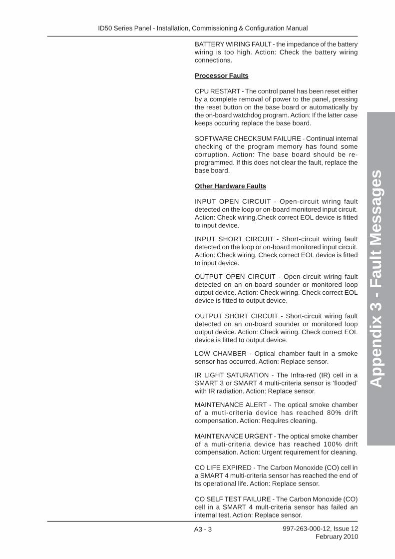
ID50 Series Panel - Installation, Commissioning & Configuration Manual
Ap
pen
dix
3 -
Fau
lt M
essa
ges
A3 - 3 997-263-000-12, Issue 12February 2010
BATTERY WIRING FAULT - the impedance of the batterywiring is too high. Action: Check the battery wiringconnections.
Processor Faults
CPU RESTART - The control panel has been reset eitherby a complete removal of power to the panel, pressingthe reset button on the base board or automatically bythe on-board watchdog program. Action: If the latter casekeeps occuring replace the base board.
SOFTWARE CHECKSUM FAILURE - Continual internalchecking of the program memory has found somecorruption. Action: The base board should be re-programmed. If this does not clear the fault, replace thebase board.
Other Hardware Faults
INPUT OPEN CIRCUIT - Open-circuit wiring faultdetected on the loop or on-board monitored input circuit.Action: Check wiring.Check correct EOL device is fittedto input device.
INPUT SHORT CIRCUIT - Short-circuit wiring faultdetected on the loop or on-board monitored input circuit.Action: Check wiring. Check correct EOL device is fittedto input device.
OUTPUT OPEN CIRCUIT - Open-circuit wiring faultdetected on an on-board sounder or monitored loopoutput device. Action: Check wiring. Check correct EOLdevice is fitted to output device.
OUTPUT SHORT CIRCUIT - Short-circuit wiring faultdetected on an on-board sounder or monitored loopoutput device. Action: Check wiring. Check correct EOLdevice is fitted to output device.
LOW CHAMBER - Optical chamber fault in a smokesensor has occurred. Action: Replace sensor.
IR LIGHT SATURATION - The Infra-red (IR) cell in aSMART 3 or SMART 4 multi-criteria sensor is ‘flooded’with IR radiation. Action: Replace sensor.
MAINTENANCE ALERT - The optical smoke chamberof a muti-criteria device has reached 80% driftcompensation. Action: Requires cleaning.
MAINTENANCE URGENT - The optical smoke chamberof a muti-criteria device has reached 100% driftcompensation. Action: Urgent requirement for cleaning.
CO LIFE EXPIRED - The Carbon Monoxide (CO) cell ina SMART 4 multi-criteria sensor has reached the end ofits operational life. Action: Replace sensor.
CO SELF TEST FAILURE - The Carbon Monoxide (CO)cell in a SMART 4 mult-criteria sensor has failed aninternal test. Action: Replace sensor.
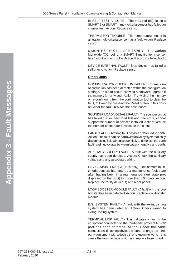
ID50 Series Panel - Installation, Commissioning & Configuration ManualA
pp
end
ix 3
- F
ault
Mes
sag
es
A3 - 4997-263-000-12, Issue 12February 2010
IR SELF TEST FAILURE - The Infra-red (IR) cell in aSMART 3 or SMART 4 mult-criteria sensor has failed aninternal test. Action: Replace sensor.
THERMISTOR TROUBLE - The temperature sensor ina heat or multi-criteria sensor has a fault. Action: Replacesensor.
6 MONTHS TO CELL LIFE EXPIRY - The CarbonMonoxide (CO) cell of a SMART 4 multi-criteria sensorhas 6 months to end of life. Action: Record in site log book.
DEVICE INTERNAL FAULT - loop device has failed aself check. Action: Replace sensor.
Other Faults
CONFIGURATION CHECKSUM FAILURE - Some formof corruption has been detected within the configurationsettings. This can occur following a software upgrade ifthe memory is not ‘wiped’. Action: Try ‘wiping’ the memoryor re-configuring from the configuration tool to clear thefault, followed by pressing the Reset button. If this doesnot clear the fault, replace the base board.
SOUNDER LOAD VOLTAGE FAULT - The sounder circuithas failed the sounder load test and, therefore, cannotsupport the number of devices installed. Action: Reducethe number of sounder devices on the circuit.
EARTH FAULT - A wiring fault has been detected to earth.Action: The fault can be narrowed down by systematicallydisconnecting field wiring sequentially and monitor the earthfault reading, voltage between battery negative and earth.
AUXILIARY SUPPLY FAULT - A fault with the auxiliarysupply has been detected. Action: Check the auxiliaryvoltage and any associated wiring.
DEVICE MAINTENANCE [ID60 only] - One or more multi-criteria sensors has entered a maintenance fault stateafter having been in a maintenance alert state (notdisplayed on the LCD) for more than 100 days. Action:Replace the faulty device(s) and reset panel.
LOOP BOOSTER MODULE FAULT - A fault with the loopbooster has been detected. Action: Replace loop boostermodule.
E.S. SYSTEM FAULT - A fault with the extinguishingsystem has been detected. Action: Check wiring toextinguishing system.
TERMINAL LINK FAULT - This indicates a fault in theequipment connected to the third-party protocol RS232port has been detected. Action: Check the cableconnections. If nothing obvious is found, change the third-party equipment with a device that is known to work. If thisclears the fault, replace unit. If not, replace base board.
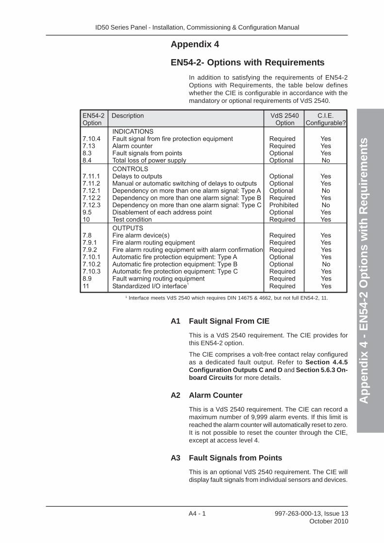
ID50 Series Panel - Installation, Commissioning & Configuration Manual
Ap
pen
dix
4 -
EN
54-2
Op
tio
ns
wit
h R
equ
irem
ents
A4 - 1 997-263-000-13, Issue 13October 2010
Appendix 4
EN54-2- Options with Requirements
In addition to satisfying the requirements of EN54-2Options with Requirements, the table below defineswhether the CIE is configurable in accordance with themandatory or optional requirements of VdS 2540.
EN54-2 Description VdS 2540 C.I.E.Option Option Configurable?
INDICATIONS7.10.4 Fault signal from fire protection equipment Required Yes7.13 Alarm counter Required Yes8.3 Fault signals from points Optional Yes8.4 Total loss of power supply Optional No
CONTROLS7.11.1 Delays to outputs Optional Yes7.11.2 Manual or automatic switching of delays to outputs Optional Yes7.12.1 Dependency on more than one alarm signal: Type A Optional No7.12.2 Dependency on more than one alarm signal: Type B Required Yes7.12.3 Dependency on more than one alarm signal: Type C Prohibited No9.5 Disablement of each address point Optional Yes10 Test condition Required Yes
OUTPUTS7.8 Fire alarm device(s) Required Yes7.9.1 Fire alarm routing equipment Required Yes7.9.2 Fire alarm routing equipment with alarm confirmation Required Yes7.10.1 Automatic fire protection equipment: Type A Optional Yes7.10.2 Automatic fire protection equipment: Type B Optional No7.10.3 Automatic fire protection equipment: Type C Required Yes8.9 Fault warning routing equipment Required Yes
11 Standardized I/O interface Required Yes1
1 Interface meets VdS 2540 which requires DIN 14675 & 4662, but not full EN54-2, 11.
A1 Fault Signal From CIE
This is a VdS 2540 requirement. The CIE provides forthis EN54-2 option.
The CIE comprises a volt-free contact relay configuredas a dedicated fault output. Refer to Section 4.4.5Configuration Outputs C and D and Section 5.6.3 On-board Circuits for more details.
A2 Alarm Counter
This is a VdS 2540 requirement. The CIE can record amaximum number of 9,999 alarm events. If this limit isreached the alarm counter will automatically reset to zero.It is not possible to reset the counter through the CIE,except at access level 4.
A3 Fault Signals from Points
This is an optional VdS 2540 requirement. The CIE willdisplay fault signals from individual sensors and devices.
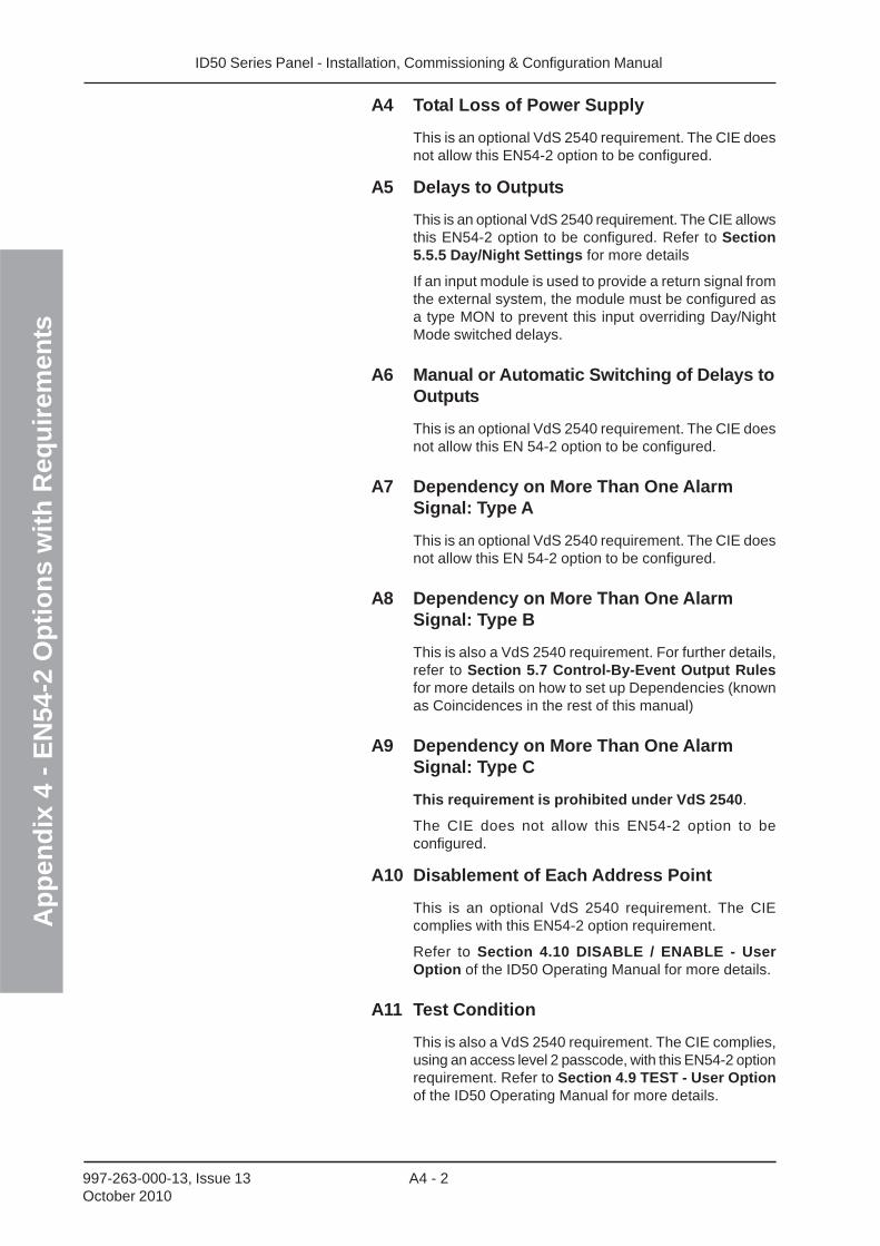
ID50 Series Panel - Installation, Commissioning & Configuration ManualA
pp
end
ix 4
- E
N54
-2 O
pti
on
s w
ith
Req
uir
emen
ts
A4 - 2997-263-000-13, Issue 13October 2010
A4 Total Loss of Power Supply
This is an optional VdS 2540 requirement. The CIE doesnot allow this EN54-2 option to be configured.
A5 Delays to Outputs
This is an optional VdS 2540 requirement. The CIE allowsthis EN54-2 option to be configured. Refer to Section5.5.5 Day/Night Settings for more details
If an input module is used to provide a return signal fromthe external system, the module must be configured asa type MON to prevent this input overriding Day/NightMode switched delays.
A6 Manual or Automatic Switching of Delays toOutputs
This is an optional VdS 2540 requirement. The CIE doesnot allow this EN 54-2 option to be configured.
A7 Dependency on More Than One AlarmSignal: Type A
This is an optional VdS 2540 requirement. The CIE doesnot allow this EN 54-2 option to be configured.
A8 Dependency on More Than One AlarmSignal: Type B
This is also a VdS 2540 requirement. For further details,refer to Section 5.7 Control-By-Event Output Rulesfor more details on how to set up Dependencies (knownas Coincidences in the rest of this manual)
A9 Dependency on More Than One AlarmSignal: Type C
This requirement is prohibited under VdS 2540.
The CIE does not allow this EN54-2 option to beconfigured.
A10 Disablement of Each Address Point
This is an optional VdS 2540 requirement. The CIEcomplies with this EN54-2 option requirement.
Refer to Section 4.10 DISABLE / ENABLE - UserOption of the ID50 Operating Manual for more details.
A11 Test Condition
This is also a VdS 2540 requirement. The CIE complies,using an access level 2 passcode, with this EN54-2 optionrequirement. Refer to Section 4.9 TEST - User Optionof the ID50 Operating Manual for more details.
ID50 Series Panel - Installation, Commissioning & Configuration Manual
Ap
pen
dix
4 -
EN
54-2
Op
tio
ns
wit
h R
equ
irem
ents
A4 - 3 997-263-000-13, Issue 13October 2010
A12 Fire Alarm Device(s)
This is also a VdS 2540 requirement. To satisfy therequirements of EN54-2 7.8 the CIE is provided with therequired access level 2 controls. Refer to Section 4.5SILENCE / RESOUND Pushbutton of the ID50Operating Manual for more details.
A13 Fire Alarm Routing Equipment (7.9.1)
This is also a VdS 2540 requirement. The CIE allowsthis EN54-2 option to be configured.
A dedicated fire output (transfer) relay is provided by theCIE. In addition, the internal sounder/relay circuits areconfigurable as remote fire outputs. The CIE provides anLED to indicate when the fire relay or any configured remotefire outputs are active. Refer to Section 4.4.5 ConfigurationOutputs C and D and Section 5.6.3 On-board Circuitsfor more details.
A14 Fire Alarm Routing Equipment with AlarmConfirmation (7.9.2)
This is also a VdS 2540 requirement. The CIE allowsthis EN54-2 option to be configured.
The CIE allows a remote fire output (transfer) to beconfigured. In addition, a fire output active condition, usinga return signal from the remote fire signal routingequipment, can be configured using one of the provideddigital input circuits. With the panel function set to VdSmode activation of a fire alarm routing equipment returnsignal drives this indicator.
Refer to Section 4.4.5 Configuration Outputs C and Dand Section 5.6.3 On-board Circuits for more detailson setting up the fire routing output. The feedback signalis connected to the on-board digital input 2.
A15 Automatic Fire Protection: Type A
This is an optional VdS 2540 requirement. The CIE allowsthe configuration of an output to fire protection equipmentusing an output module. Refer to Section 5.6.1Signalling Line Circuit (SLC) - Devices for more details.
A16 Automatic Fire Protection: Type B
This is an optional VdS 2540 requirement. The CIE doesnot allow this option to be configured.
A17 Automatic Fire Protection: Type C
This is an optional VdS 2540 requirement. The CIE allowsthe configuration of an output to fire protection equipment,together with associated feedback signals, using a M221-SIloop module, located internally. An Extinguishing System(SST) display unit is also required. More details can be foundin documents 997-581-000-1 (Installing the M221-SI Module)and 997-580-000-1 (Installing the NF-SST Display Box).
ID50 Series Panel - Installation, Commissioning & Configuration ManualA
pp
end
ix 4
- E
N54
-2 O
pti
on
s w
ith
Req
uir
emen
ts
A4 - 4997-263-000-13, Issue 13October 2010
A18 Fault Warning Routing Equipment
This is also a VdS 2540 requirement. The CIE allowsthis EN54-2 option to be configured.
The CIE may be configured to provide a fault signal toexternal equipment, such as a fault transmission router,using a M710-CZ module. Refer to the end of thisappendix for more details.
A19 Standardized I/O Interface
This is also a VdS 2540 requirement. The CIE does notfully support the requirements of EN54 Section 11.However, it does meet the requirements of VdS 2540which requires the ability to connect to an FBF (firebrigade panel). More details can be found in theappropriate, translated product manuals.
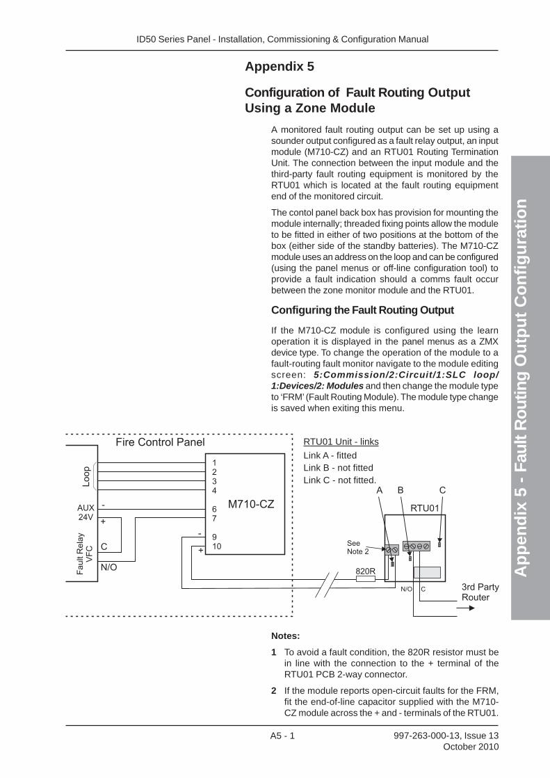
ID50 Series Panel - Installation, Commissioning & Configuration Manual
Ap
pen
dix
5 -
Fau
lt R
ou
ting
Ou
tpu
t C
on
fig
ura
tio
n
A5 - 1 997-263-000-13, Issue 13October 2010
Appendix 5
Configuration of Fault Routing OutputUsing a Zone Module
A monitored fault routing output can be set up using asounder output configured as a fault relay output, an inputmodule (M710-CZ) and an RTU01 Routing TerminationUnit. The connection between the input module and thethird-party fault routing equipment is monitored by theRTU01 which is located at the fault routing equipmentend of the monitored circuit.
The contol panel back box has provision for mounting themodule internally; threaded fixing points allow the moduleto be fitted in either of two positions at the bottom of thebox (either side of the standby batteries). The M710-CZmodule uses an address on the loop and can be configured(using the panel menus or off-line configuration tool) toprovide a fault indication should a comms fault occurbetween the zone monitor module and the RTU01.
Configuring the Fault Routing Output
If the M710-CZ module is configured using the learnoperation it is displayed in the panel menus as a ZMXdevice type. To change the operation of the module to afault-routing fault monitor navigate to the module editingscreen: 5:Commission/2:Circuit/1:SLC loop/1:Devices/2: Modules and then change the module typeto ‘FRM’ (Fault Routing Module). The module type changeis saved when exiting this menu.
Fire Control Panel
M710-CZ
1234
67
910
Lo
op
AUX24V
Fault
Rela
yV
FC
RTU01-
-
+
+C
N/O 820R
A B C
3rd PartyRouter
N/O C
SeeNote 2
RTU01 Unit - links
Link A - fittedLink B - not fittedLink C - not fitted.
Notes:
1 To avoid a fault condition, the 820R resistor must bein line with the connection to the + terminal of theRTU01 PCB 2-way connector.
2 If the module reports open-circuit faults for the FRM,fit the end-of-line capacitor supplied with the M710-CZ module across the + and - terminals of the RTU01.

Charles Avenue
Burgess Hill
W. Sussex
RH15 9UF
Every care has been taken in the preparation of this document but no liability can be accepted for the use of the information therein. Design features may be changed or amended without prior notice.
Quality Systems Certificate No. 154Assessed to ISO9001
LO
SS
PR
EV
EN
T
ION
CERTIFICAT
ION
BO
A
RD
007
T: +44 (0) 1444 230 300
F: +44 (0) 1444 230 888
www.notifierfiresystems.co.uk
local distributor