Embed Size (px)
DESCRIPTION
mm,,,,,,,,,,,,,,;lk
Citation preview
1818 IEEE TRANSACTIONS ON ELECTRON DEVICES, VOL. 61, NO. 6, JUNE 2014
Simulation and Experiment of aKu-Band Gyro-TWT
Jianxun Wang, Yong Luo, Yong Xu, Ran Yan, Youlei Pu, Xue Deng, and Hai Wang
Abstract— Design techniques and experimental results arepresented on a Ku-band TE11 mode gyro-traveling wave tube.The hot test of this amplifier gives more than 153-kW outputpower, 2.3-GHz bandwidth (14%), 41-dB saturated gain, and20% efficiency driven by a 63 kV, 12-A electron beam with apitch angle (vt vz) of 1.2, and velocity spread of 5%. A linearpolarized TE11 mode input coupler is used to introduce the inputpower. The stability of the amplifier from oscillation, includingboth the operating TE11 mode and the backward wave TE21mode, has been investigated with linear codes, nonlinear self-consistent theory, and 3-D PIC CHIPIC simulation. To suppressthe potential gyro-backward wave oscillator interactions, thehigh frequency circuit is loaded with lossy ceramic rings. Thelossy structure is optimized by nonlinear theory and 3-D PICsimulation. A low velocity spread magnetron injection gun isdesigned with a new structure.
Index Terms— Absolute instability, gyro-TWT, high powermillimeter-wave amplifier, Ku-band, lossy ceramic, magnetroninjection gun (MIG), TE11 mode.
I. INTRODUCTION
H IGH-power microwave and millimeter-wave sourceshave been extensively researched for a variety of appli-
cations, including high-resolution radars, wideband communi-cations, dynamic nuclear polarization, and so on [1]–[3]. Thegyro-traveling wave tube (gyro-TWT) is an attractive candi-date for use as the transmitter power amplifier in millimeter-wave radars [4]. Gyro-TWTs not only are capable of muchbroader bandwidth than other high power tubes, such as gyro-klystrons, while retaining the high power at high frequency,but also can provide much higher output power even at lowerfrequency compared with traditional TWTs. In spite of thefact that the background theory of gyro-TWT was developedalmost simultaneously or even earlier than that of the gyrotron,the first experimental tubes yielding parameters attractive forapplications were elaborated upon only in the last 20 years [4].The main problems with the realization of a gyro-TWT canbe attributed to an important issue: maintaining stability tobackward wave oscillation in the interaction space, while atthe same time allowing for acceptable performance in theoperating mode, including high overall gain, stability to local
Manuscript received October 14, 2013; revised December 16, 2013;accepted December 19, 2013. Date of publication April 4, 2014; date ofcurrent version May 16, 2014. This work was supported by the NationalNatural Science Foundation of China under Grant G051040161101040. Thereview of this paper was arranged by Editor M. Blank.
The authors are with the School of Physical Electronics, University ofElectronic Science and Technology of China, Chengdu 610054, China (e-mail:[email protected]; [email protected]; [email protected]).
Color versions of one or more of the figures in this paper are availableonline at http://ieeexplore.ieee.org.
Digital Object Identifier 10.1109/TED.2013.2296552
reflective oscillations, and high average power capability. Inaddition, the high sensitivity to electron velocity spread is alsoan important factor [5].
At present, the mode instability problems of gyro-TWTsare solved in [6] and [7]. He reported successful experimentsbased on the operation of a gyro-TWT at the fundamentalcyclotron resonance with a circular waveguide having highlosses along the majority of its length and relatively shortunloaded output section. All of the spurious modes are sup-pressed by the heavily loaded interaction circuit. To increasethe average power handling capability, the structure of lossyceramic materials interspaced with metal rings is used in thispaper.
Utilizing these techniques, gyro-TWT research has madesignificant strides in various frequency regions over the lasttwo decades. Early 35-GHz gyro-TWT research includedan experiment at the NRL, which produced 16.6-kW peakpower, 20-dB saturated gain, and 7.8% efficiency with a3-dB bandwidth of 1.5% [8]. Harmonic gyro-TWTs havebeen investigated at the University of California, Davis, CA,where a second harmonic gyro-TWT in the Ku-band produced207-kW output power, 16-dB saturated gain with 12.9% effi-ciency, and a bandwidth of 2.1% [9]. Also at the Universityof California, a gyro-TWT partially loaded with dielectricproduced 55-kW peak output power, 27-dB saturated gain, anda 3-dB bandwidth of 11% in the X-band frequency range [10].At the National Tsing Hua University, Taiwan, an ultrahighgain gyro-TWT amplifier produced 93-kW peak power, with70-dB saturated gain, 26.5% efficiency, and a −3-dB band-width of 8.6% [4]. This unprecedented gain from a gyro-TWT was achieved by employing distributed wall losses tosuppress spurious oscillations. University of California Davishas performed the W -Band state-of-the-art gyro-TWT with a140-kW output power [11], [12]. Other gyro-TWT work hasbeen performed at the University of Maryland, College Park,at 32 GHz [13], [14], and a 35-GHz spiral waveguide gyro-TWT has been demonstrated by collaboration between theUniversity of Strathclyde, Glasgow, U.K., and the Institute ofApplied Physics, Nizhny Novgorod, Russia, [15]. In addition,MIT built a 140-GHz quasi-optical gyro-TWT employing aconfocal waveguide for high-order mode operation [16].
In UESTC, we have developed a high power, widebandKu-band gyro-TWT aimed at Ku-band radar project. Since thesuperconductor used in our experiment was designed for aKu-band gyro-TWT, the length of the flat section of magneticfield is only ∼300 mm, which is not long enough for aKu-band design [17]. In addition, the maximum output powerof our solid-state amplifier is only ∼200 W. Consequently,
0018-9383 © 2014 IEEE. Personal use is permitted, but republication/redistribution requires IEEE permission.See http://www.ieee.org/publications_standards/publications/rights/index.html for more information.
WANG et al.: SIMULATION AND EXPERIMENT OF A KU-BAND GYRO-TWT 1819
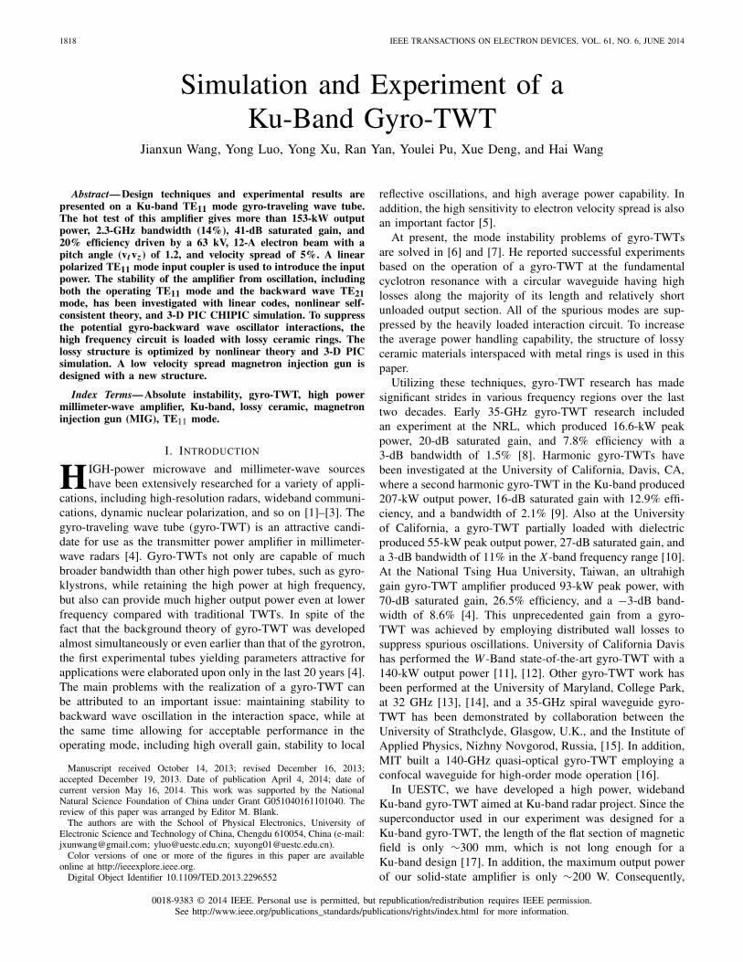
Fig. 1. Structure and beam distribution of the new-type MIG.
this limits the working mode selection. The TE01 mode canprovide much higher power and it is also much easier todesign the magnetron injection gun (MIG) due to the low beamdensity near the cathode, while the TE11 mode can providemuch higher gain. Consequently, our gyro-TWT is designedto operate in the TE11 mode at the first harmonic in orderto provide high gain and wide bandwidth. The beam voltageis 70 kV and the beam current is ∼10 A. It is noted that inorder to enhance the efficiency and gain with a short lengthsuperconductor magnet, a pitch factor of 1.2 is chosen in ourdesign. The design of a high beam density and low magneticfield near the cathode emission area is also a challengingtarget. The 2-D and 3-D PIC simulations are performed byCHIPIC [18]. The new MIG structure with two focus polesis optimized by 2-D PIC simulation. The lossy ceramic ringsspaced with a metal ring RF structure are used in our designto overcome the backward wave osculation. Linear theory andnonlinear theory are used to analyze the stability problems ofthe TE21 backward wave oscillation and the TE11 absoluteinstability. The beam-wave interaction is studied by numericalnonlinear calculation and 3-D PIC simulations. The simulationand cold test results of a circulator and linear polarized inputcoupler are also given below.
The organization of this paper is as follows. The new-typemagnetron injection gun design is presented in Section II-A.Section II-B describes a circular polarized and a linear polar-ized TE11 mode coupler design. The TE11 and TE21 modeinstabilities, the gyro-TWT circuit, and the loss requiredfor the amplifier’s stability are determined in Section II-C.Section II-D describes the nonlinear large-signal characteris-tics of the amplifier. The results of a 3-D PIC simulation ofTE11 mode beam-wave interaction and experimental hot testare presented in Section II-E. Finally, conclusions are drawnin Section III.
II. SIMULATION AND EXPERIMENTAL STUDY
A. Magnetron Injection Gun
The MIG gun is designed and optimized through PICsimulations. As can be seen from Fig. 1, this double anodeMIG has two focus poles. The potential of the first anodeis −30 kV, the cathode is −70 kV, and the second anode is0 kV. The radius is 5 mm and the width is 4 mm. The magneticfield at the right end is 0.55 T and is ∼0.065 T at the cathodeemission area. The traditional MIG type is not applicable forsuch a low magnetic field in the emission region. As canbe seen, after the electrons are emitted from the cathode,
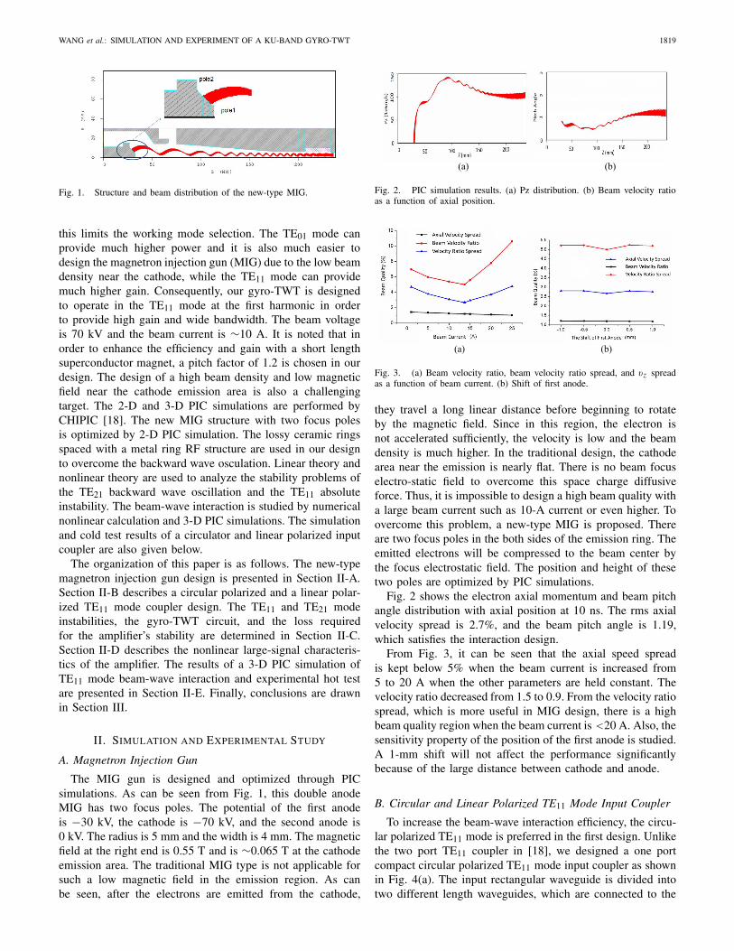
Fig. 2. PIC simulation results. (a) Pz distribution. (b) Beam velocity ratioas a function of axial position.
Fig. 3. (a) Beam velocity ratio, beam velocity ratio spread, and vz spreadas a function of beam current. (b) Shift of first anode.
they travel a long linear distance before beginning to rotateby the magnetic field. Since in this region, the electron isnot accelerated sufficiently, the velocity is low and the beamdensity is much higher. In the traditional design, the cathodearea near the emission is nearly flat. There is no beam focuselectro-static field to overcome this space charge diffusiveforce. Thus, it is impossible to design a high beam quality witha large beam current such as 10-A current or even higher. Toovercome this problem, a new-type MIG is proposed. Thereare two focus poles in the both sides of the emission ring. Theemitted electrons will be compressed to the beam center bythe focus electrostatic field. The position and height of thesetwo poles are optimized by PIC simulations.
Fig. 2 shows the electron axial momentum and beam pitchangle distribution with axial position at 10 ns. The rms axialvelocity spread is 2.7%, and the beam pitch angle is 1.19,which satisfies the interaction design.
From Fig. 3, it can be seen that the axial speed spreadis kept below 5% when the beam current is increased from5 to 20 A when the other parameters are held constant. Thevelocity ratio decreased from 1.5 to 0.9. From the velocity ratiospread, which is more useful in MIG design, there is a highbeam quality region when the beam current is <20 A. Also, thesensitivity property of the position of the first anode is studied.A 1-mm shift will not affect the performance significantlybecause of the large distance between cathode and anode.
B. Circular and Linear Polarized TE11 Mode Input Coupler
To increase the beam-wave interaction efficiency, the circu-lar polarized TE11 mode is preferred in the first design. Unlikethe two port TE11 coupler in [18], we designed a one portcompact circular polarized TE11 mode input coupler as shownin Fig. 4(a). The input rectangular waveguide is divided intotwo different length waveguides, which are connected to the
1820 IEEE TRANSACTIONS ON ELECTRON DEVICES, VOL. 61, NO. 6, JUNE 2014
Fig. 4. Circular polarized TE11 input coupler. (a) Structure and HFSSsimulation. (b) Axial ratio.
Fig. 5. Linear polarized TE11 input coupler. (a) Structure include pillow boxwindow. (b) S21 cold test results.
Fig. 6. Configuration of the TE11 mode Ku-band gyro-TWT interactioncircuit.
circular waveguide with 90° difference. From HFSS simula-tion, the TE10 mode is converted to the circular polarized TE11mode. The axial ratio of the excited TE11 mode in circularwaveguide is studied. In the region between 15 and 17 GHz,the axial ratio is kept <2. The transmission parameter S21 isgreater than −0.2 dB in this frequency band.
A linear polarized TE11 input coupler as shown in Fig. 5 isused in our experimental test for the simple structure. In thecold test, a pillow box-type input window is included. Itprovides more than 3 GHz −3-dB bandwidth, which meetsthe design requirement.
C. Mode Instabilities and Loss Loading
The interaction section configuration of the gyro-TWT inour experiment is shown in Fig. 6. The gyro-TWT circuitis comprised of the input coupler copper section, the loadedinteraction section, the unloaded interaction section, and thelinear or nonlinear output taper. The detailed design of theloading requirement in the RF circuit and mode instabilities isdiscussed in this section. The total length of the input coupler,the loaded interaction section, and unloaded interaction is∼300 mm according to the length of our superconductor
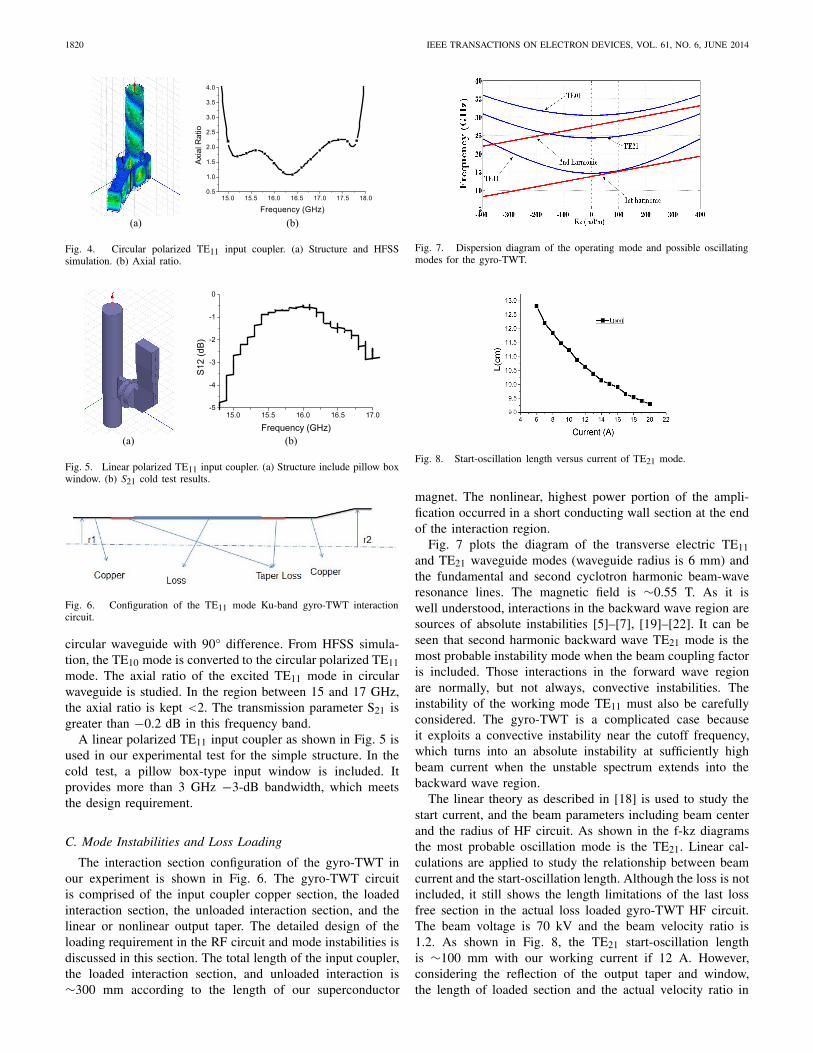
Fig. 7. Dispersion diagram of the operating mode and possible oscillatingmodes for the gyro-TWT.
Fig. 8. Start-oscillation length versus current of TE21 mode.
magnet. The nonlinear, highest power portion of the ampli-fication occurred in a short conducting wall section at the endof the interaction region.
Fig. 7 plots the diagram of the transverse electric TE11and TE21 waveguide modes (waveguide radius is 6 mm) andthe fundamental and second cyclotron harmonic beam-waveresonance lines. The magnetic field is ∼0.55 T. As it iswell understood, interactions in the backward wave region aresources of absolute instabilities [5]–[7], [19]–[22]. It can beseen that second harmonic backward wave TE21 mode is themost probable instability mode when the beam coupling factoris included. Those interactions in the forward wave regionare normally, but not always, convective instabilities. Theinstability of the working mode TE11 must also be carefullyconsidered. The gyro-TWT is a complicated case becauseit exploits a convective instability near the cutoff frequency,which turns into an absolute instability at sufficiently highbeam current when the unstable spectrum extends into thebackward wave region.
The linear theory as described in [18] is used to study thestart current, and the beam parameters including beam centerand the radius of HF circuit. As shown in the f-kz diagramsthe most probable oscillation mode is the TE21. Linear cal-culations are applied to study the relationship between beamcurrent and the start-oscillation length. Although the loss is notincluded, it still shows the length limitations of the last lossfree section in the actual loss loaded gyro-TWT HF circuit.The beam voltage is 70 kV and the beam velocity ratio is1.2. As shown in Fig. 8, the TE21 start-oscillation lengthis ∼100 mm with our working current if 12 A. However,considering the reflection of the output taper and window,the length of loaded section and the actual velocity ratio in
WANG et al.: SIMULATION AND EXPERIMENT OF A KU-BAND GYRO-TWT 1821
Fig. 9. Interaction efficiency of the most likely oscillating modes (a) TE11and (b) TE21 as function of the beam current. For each mode, the oscillationstarts at the beam current at which the efficiency approaches zero.
the experiment, the loss free section of the RF circuit shouldbe much shorter than the linear prediction. Note that thislength can be determined accurately by the following nonlinearcalculation and PIC simulation.
In order to accurately study the start-oscillation current,design the loss-loaded section, loss free section, and thebeam-wave interaction performance, the nonlinear theory cal-culation is needed. The loss loaded RF circuit configurationof our Ku-band gyro-TWT is shown in Fig. 6. The start-oscillation current of the TE21 and TE11 modes is investigatedby the method of interaction efficiency calculation as describedin [5]. The interaction efficiency of the TE11 mode as afunction of beam current is calculated by the nonlinear theory.The beam voltage is 70 kV and the velocity ratio is 1.2 in thecalculation. The wall resistivity is 30 000 times that of idealcopper in the calculation. It can be seen from Fig. 9(a) thatthe start oscillation current is ∼17 A and the frequency is14.9 GHz. These losses correspond to a −75-dB attenuationof the entire loss section. The backward wave oscillation ofthe TE21 mode is also shown in Fig. 9(b); the start oscillationcurrent is ∼16 A when the wall resistivity is 10 000 timesthat of ideal copper. The corresponding oscillation frequencyis 25.5 GHz. In this case, the total attenuation of the circuitis about −30 dB.
In the actual high average power tube, the high-thermalconductivity BeO-SiC lossy ceramic rings are used rather thanthe coated distributed-loss structure as presented in [23]. Theselossy ceramic rings spaced with a metal ring RF structure havehigher average power handling capability [24], and it is alsomuch easier to control the loading of a normally propagatingoperating mode. Since the attenuation is dependent upon onthe radius and thickness of the ceramic in electromagnetics,the variation of the attenuation dependence upon thicknessis studied. A code, based on the mode matching technique,is written to calculate the hybrid waves in the vacuum anddielectric regions as shown in Fig. 10. There are severalmaximum attenuation positions at different thicknesses. Fromthis result, the optimum thickness can be chosen.
D. Nonlinear Numerical Calculations
A large signal self-consistent code based on [7] thataccounts for loss and the electron beam spread is used toevaluate the performance characteristics of the device. Thedistributed wall loss is shown in Fig. 1, the reflections fromthe finite mismatch of the input and output couplers and the
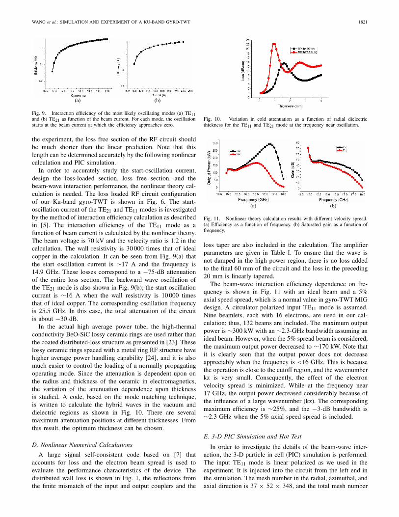
Fig. 10. Variation in cold attenuation as a function of radial dielectricthickness for the TE11 and TE21 mode at the frequency near oscillation.
Fig. 11. Nonlinear theory calculation results with different velocity spread.(a) Efficiency as a function of frequency. (b) Saturated gain as a function offrequency.
loss taper are also included in the calculation. The amplifierparameters are given in Table I. To ensure that the wave isnot damped in the high power region, there is no loss addedto the final 60 mm of the circuit and the loss in the preceding20 mm is linearly tapered.
The beam-wave interaction efficiency dependence on fre-quency is shown in Fig. 11 with an ideal beam and a 5%axial speed spread, which is a normal value in gyro-TWT MIGdesign. A circulator polarized input TE11 mode is assumed.Nine beamlets, each with 16 electrons, are used in our cal-culation; thus, 132 beams are included. The maximum outputpower is ∼300 kW with an ∼2.3-GHz bandwidth assuming anideal beam. However, when the 5% spread beam is considered,the maximum output power decreased to ∼170 kW. Note thatit is clearly seen that the output power does not decreaseappreciably when the frequency is <16 GHz. This is becausethe operation is close to the cutoff region, and the wavenumberkz is very small. Consequently, the effect of the electronvelocity spread is minimized. While at the frequency near17 GHz, the output power decreased considerably because ofthe influence of a large wavenumber (kz). The correspondingmaximum efficiency is ∼25%, and the −3-dB bandwidth is∼2.3 GHz when the 5% axial speed spread is included.
E. 3-D PIC Simulation and Hot Test
In order to investigate the details of the beam-wave inter-action, the 3-D particle in cell (PIC) simulation is performed.The input TE11 mode is linear polarized as we used in theexperiment. It is injected into the circuit from the left end inthe simulation. The mesh number in the radial, azimuthal, andaxial direction is 37 × 52 × 348, and the total mesh number
1822 IEEE TRANSACTIONS ON ELECTRON DEVICES, VOL. 61, NO. 6, JUNE 2014
Fig. 12. 3-D PIC simulation. (a) Beam distribution in the cross section.(b) Beam distribution in the axial direction.
Fig. 13. (a) Beam energy distribution as a function of axial position.(b) Output power as a function of frequency.
Fig. 14. Output character of the output port. (a) Output power at 16 GHzas a function of time. (b) Spectrum of the output transverse electrified.
is 669 552. More than 200 000 electrons are included in thesimulation. Fig. 12 shows the beam distribution of the 3-DPIC simulation. The circuit include the input loss free section,the loss loaded section, and the output loss free section andsimple linear output taper. The ideal 70 kV, 10-A beam isinjected into the RF circuit from the left end. The beam centeris ∼2.4 mm. It can be seen that there is a strong beam waveinteraction at the output loss free section. From Fig. 13(a),it can be seen that most of the electrons lost their energyrapidly after entering the output loss free section. While thereare still some electrons which gain energy, it is necessary topay close attention to collecting of them. They can traversea much longer distance in the axial direction. Consequently,an output window with improper position will probably becracked by these electrons. The saturated output power as afunction of frequency is shown in Fig. 13(b). The maximumoutput power is ∼177 kW with a 25% efficiency at 16.8 GHz.The differences between the nonlinear theory calculation andsimulation results may be caused by the difference of the lossycircuit model. In addition, the space charge effect, the realaxial magnetic field, and more electrons are included in thePIC simulation.
The temporal dependence of output power is shown inFig. 14(a). The output power becomes stable at ∼6 ns.
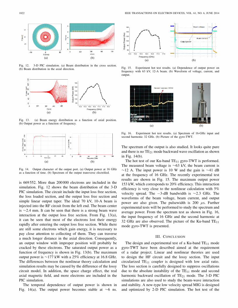
Fig. 15. Experiment hot test results. (a) Dependence of output power onfrequency with 63 kV, 12-A beam. (b) Waveform of voltage, current, andoutput.
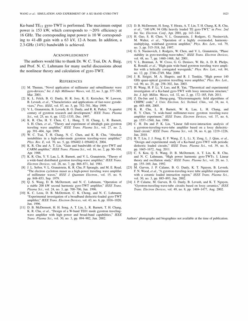
Fig. 16. Experiment hot test results. (a) Spectrum of 16-GHz input andsecond harmonic 32 GHz. (b) Picture of the gyro-TWT.
The spectrum of the output is also studied. It looks quite pureand there is no TE21 mode backward wave oscillation as shownin Fig. 14(b).
The hot test of our Ku-band TE11 gyro-TWT is performed.The measured beam voltage is ∼63 kV, the beam current is∼12 A. The input power is 10 W and the gain is ∼41 dBat the frequency of 16 GHz. The recently experimental testresults are shown in Fig. 15. The maximum output power153 kW, which corresponds to 20% efficiency. This interactionefficiency is very close to the nonlinear calculation with 5%velocity spread. The −3-dB bandwidth is ∼2.3 GHz. Thewaveforms of the beam voltage, beam current, and outputpower are also given. The pulsewidth is 200 µs. Furtherexperimental tests will be performed to study the spectrum andaverage power. From the spectrum test as shown in Fig. 16,the input frequency of 16 GHz and the second harmonic at32 GHz are also observed. The picture of the Ku-band TE11mode gyro-TWT is presented.
III. CONCLUSION
The design and experimental test of a Ku-band TE11 modegyro-TWT have been described aimed at the requirementof a radar project. Linear and nonlinear theories are usedto design the HF circuit and the lossy section. The inputcircularized TE11 coupler is designed with low axial ratio.The loss section is carefully designed to suppress oscillationsdue to the absolute instability of the TE11 mode and secondharmonic backward oscillation of TE21 mode. The 3-D PICsimulations are also used to study the beam-wave interactionand stability. A new-type low velocity spread MIG is designedand optimized by 2-D PIC simulation. The hot test of the
WANG et al.: SIMULATION AND EXPERIMENT OF A KU-BAND GYRO-TWT 1823
Ku-band TE11 gyro-TWT is performed. The maximum outputpower is 153 kW, which corresponds to ∼20% efficiency at16 GHz. The corresponding input power is 10 W correspond-ing to 41-dB gain with a 63 kV, 12-A beam. In addition, a2.3-GHz (14%) bandwidth is achieved.
ACKNOWLEDGMENT
The authors would like to thank Dr. W. C. Tsai, Dr. A. Baig,and Prof. N. C. Luhmann for many useful discussions aboutthe nonlinear theory and calculation of gyro-TWT.
REFERENCES
[1] M. Thumm, “Novel application of millimeter and submillimeter wavegyro-devices,” Int. J. Infr. Millimeter Waves, vol. 22, no. 3, pp. 377–385,Mar. 2001.
[2] K. L. Felch, B. G. Danly, H. R. Jory, K. E. Kreischer, W. Lawson,B. Levush, et al., “Characteristics and applications of fast-wave gyrode-vices,” Proc. IEEE, vol. 87, no. 5, pp. 752–781, May 1999.
[3] V. L. Granatstein, B. Levush, B. G. Danly, and R. K. Parker, “A quartercentury of gyrotron research and development,” IEEE Trans. PlasmaSci., vol. 25, no. 6, pp. 1322–1335, Dec. 1997.
[4] K. R. Chu, H. Y. Chen, C. L. Hung, T. H. Chang, L. R. Barnett,S. H. Chen, et al., “Theory and experiment of ultrahigh gain gyrotrontraveling wave amplifier,” IEEE Trans. Plasma Sci., vol. 27, no. 2,pp. 391–404, Apr. 1999.
[5] W. C. Tsai, T. H. Chang, N. C. Chen, and K. R. Chu, “Absoluteinstabilities in a high-order-mode gyrotron traveling-wave amplifier,”Phys. Rev. E, vol. 70, no. 5, pp. 056402-1–056402-8, 2004.
[6] K. R. Chu and A. T. Lin, “Gain and bandwidth of the gyro-TWT andCARM amplifier,” IEEE Trans. Plasma Sci., vol. 16, no. 2, pp. 90–104,Apr. 1988.
[7] K. R. Chu, Y. Y. Lau, L. R. Barnett, and V. L. Granatstein, “Theory ofa wide-band distributed gyrotron traveling-wave amplifier,” IEEE Trans.Electron Devices, vol. 28, no. 7, pp. 866–871, Jul. 1981.
[8] J. L. Seftor, V. L. Granatstein, K. R. Chu, P. Sprangle, and M. E. Read,“The electron cyclotron maser as a high-power traveling wave amplifierof millimeter waves,” IEEE J. Quantum Electron., vol. 15, no. 9,pp. 848–853, Sep. 1979.
[9] Q. S. Wang, D. B. McDermott, and N. C. Luhmann, “Operation ofa stable 200 kW second harmonic gyro-TWT amplifier,” IEEE Trans.Plasma Sci., vol. 24, no. 3, pp. 700–706, Jun. 1996.
[10] K. C. Leou, D. B. McDermott, C. K. Chong, and N. C. Luhmann,“Experimental investigation of a broadband dielectric-loaded gyro-TWTamplifier,” IEEE Trans. Electron Devices, vol. 43, no. 6, pp. 1016–1020,Jun. 1996.
[11] D. B. McDermott, H. H. Song, A. T. Lin, L. R. Barnett, T. H. Chang,K. R. Chu, et al., “Design of a W-band TE01 mode gyrotron traveling-wave amplifier with high power and broad-band capabilities,” IEEETrans. Plasma Sci., vol. 30, no. 3, pp. 894–902, Jun. 2002.
[12] D. B. McDermott, H. Song, Y. Hirata, A. T. Lin, T. H. Chang, K. R. Chu,et al., “140 kW, 94 GHz heavily loaded TE gyro-TWT,” in Proc. 2ndInt. Vac. Electron. Conf., Apr. 2001, pp. 143–144.
[13] H. Guo, S. H. Chen, V. L. Granatstein, J. Rodgers, G. Nusinovich,M. Walter, et al., “Operation of a highly overmoded, harmonic-multiplying, wideband gyrotron amplifier,” Phys. Rev. Lett., vol. 79,no. 3, pp. 515–518, Jul. 1997.
[14] G. S. Nusinovich, J. Rodgers, W. Chen, and V. L. Granatstein, “Phasestability in gyro-traveling-wave-tubes,” IEEE Trans. Electron Devices,vol. 48, no. 7, pp. 1460–1468, Jul. 2001.
[15] V. L. Bratman, A. W. Cross, G. G. Denisov, W. He, A. D. R. Phelps,K. Ronald, et al., “High-gain wide-band gyrotron traveling wave ampli-fier with a helically corrugated waveguide,” Phys. Rev. Lett., vol. 84,no. 12, pp. 2746–2749, Mar. 2000.
[16] J. R. Sirigiri, M. A. Shaprio, and R. J. Temkin, “High power 140GHz quasi-optical gyrotron travelling wave amplifier,” Phys. Rev. Lett.,vol. 90, no. 25, pp. 258–302, Jun. 2003.
[17] H. Wang, H. F. Li, Y. Luo, and R. Yan, “Theoretical and experimentalinvestigation of a Ka-band gyro-TWT with lossy interaction structure,”Int. J. Infr. Millim. Waves, vol. 32, no. 2, pp. 172–185, Feb. 2011.
[18] Z. Da-Jun and L. Sheng-gang, “Electronmagnetic field algorithms ofCHIPIC code,” J. Univ. Electron. Sci. Technol. Chin., vol. 34, no. 4,pp. 485–488, 2005.
[19] K. R. Chu, L. R. Barnett, W. K. Lau, L. H. Chang, andH. Y. Chen, “A wide-band millimeter-wave gyrotron traveling-waveamplifier experiment,” IEEE Trans. Electron Devices, vol. 37, no. 6,pp. 1557–1560, Jun. 1990.
[20] C. H. Du and P. K. Liu, “Linear full-wave-interaction analysis ofa gyrotron-traveling-wave-tube amplifier based on a lossy dielectric-lined circuit,” IEEE Trans. Plasma Sci., vol. 38, no. 6, pp. 1219–1226,Jun. 2010.
[21] B. T. Liu, J. J. Feng, E. F. Wang, Z. L. Li, X. Zeng, L. J. Qian, et al.,“Design and experimental study of a Ka-band gyro-TWT with periodicdielectric loaded circuits,” IEEE Trans. Plasma Sci., vol. 39, no. 8,pp. 1665–1672, Aug. 2011.
[22] C. S. Kou, Q. S. Wang, D. B. McDermott, A. T. Lin, K. R. Chu,and N. C. Luhmann, “High power harmonic gyro-TWTs. I. Lineartheory and oscillation study,” IEEE Trans. Plasma Sci., vol. 20, no. 3,pp. 155–169, Jun. 1992.
[23] M. Garven, J. P. Calame, B. G. Danly, K. T. Nguyen, B. Levush,F. N. Wood, et al., “A gyrotron-traveling-wave tube amplifier experimentwith a ceramic loaded interaction region,” IEEE Trans. Plasma Sci.,vol. 30, no. 3, pp. 885–893, Jun. 2002.
[24] J. P. Calame, M. Garven, B. G. Danly, B. Levush, and K. T. Nguyen,“Gyrotron-traveling-wave-tube circuits based on lossy ceramics,” IEEETrans. Electron Devices, vol. 49, no. 8, pp. 1469–1477, Aug. 2002.
Authors’ photographs and biographies not available at the time of publication.


