Embed Size (px)
DESCRIPTION
new
Citation preview
IEEE TRANSACTIONS ON INDUSTRIAL ELECTRONICS, VOL. 61, NO. 6, JUNE 2014 2795
Two Degrees of Freedom Active Damping Techniquefor LCL Filter-Based Grid Connected PV Systems
Moin Hanif, Member, IEEE, Vinod Khadkikar, Member, IEEE,Weidong Xiao, Member, IEEE, and James L. Kirtley, Jr., Fellow, IEEE
Abstract—In grid connected photovoltaic (PV) systems, low-pass filters are utilized to reduce injected current harmonics.LCL filters have recently drawn attention for PV system gridinterfaces due to their small size and they have shown betterattenuation to switching harmonics than simple L filters. However,the LCL filter causes resonance resulting in oscillation and in-stability issues. This paper proposes an effective active dampingtechnique by introducing a two-degree-of-freedom (2DOF) PIDcontrol structure. The 2DOF control structure allows the indepen-dent action of PI and D terms giving two degrees of freedom. Thedesign is based on a typical three-phase grid-tied PV system. Theactive damping control loop is formed by using the existing gridside inductor currents and thus eliminating the need of additionalsensors. The relative stability is illustrated in frequency domain byusing bode plots. A real-time hardware-in-loop study is performedto validate the performance of the proposed 2DOF technique todamp out the LCL filter resonance.
Index Terms—Active damping, LCL filter, photovoltaic (PV)system and resonance damping.
I. INTRODUCTION
CONCERNS related to the increasing costs of conven-tional energy, greenhouse gas emissions, and security of
centralized power generations have forced the power industryto move toward a decentralized distributed generation (DG)system. These DG units are integrated into the low voltage (LV)power distribution systems and are used to deliver renewableand clean energy such as PV power, wind power, and fuelcell power to the utility through the interfacing inverters. Grid-connected DG systems come as pulse width modulated (PWM)voltage source inverters (VSIs) that can inject controlled activeand reactive powers as required. Output currents of such aninverter need to be filtered to prevent the current harmonicsaround the switching frequency from entering the utility grid[1]. A third order LCL filter is preferred over an L or LCfilter due to the 60 dB/decade attenuation of the frequenciesabove the resonance frequency and the reduction in physical
Manuscript received November 23, 2012; revised February 18, 2013 andApril 21, 2013; accepted June 24, 2013. Date of publication July 24, 2013; dateof current version December 20, 2013. This work was supported by MasdarInstitute of Science and Technology under MI-MIT grant (Award 10PAMA1).
M. Hanif is with the Department of Electrical Engineering, University ofCape Town, Rondebosch 7701, South Africa (e-mail: [email protected]).
V. Khadkikar and W. Xiao are with the Institute Center for Energy, MasdarInstitute of Science and Technology, Abu Dhabi, United Arab Emirates (e-mail:[email protected]; [email protected]).
J. L. Kirtley, Jr. is with the Massachusetts Institute of Technology,Cambridge, MA 02139 USA (e-mail: [email protected]).
Color versions of one or more of the figures in this paper are available onlineat http://ieeexplore.ieee.org.
Digital Object Identifier 10.1109/TIE.2013.2274416
size of the inductor [2]. A small inductance in an LCL filter iseffective, as the capacitor impedance is inversely proportionalto the frequency of the current. The LCL filter exhibits firstorder inductive behavior to allow proper current control andhigh frequency rejection to guarantee proper filtering. However,an LCL filter can cause stability problems due to the undesiredresonance caused by zero impedance at certain frequencies.
To avoid this resonance from contaminating the system, sev-eral damping techniques have been proposed [1]–[14]. One wayis to incorporate a physical passive element, such as, a resistorin series with the filter capacitor [3]. This passive technique,however, causes power loss in the added passive element andreduces the overall LCL-based system efficiency. A secondapproach is to modify the LCL inverter control structure suchthat the damping is achieved without any power loss [1], [2],[4]–[14]. An active damping control loop is introduced aroundthe inverter to introduce a negative peak that compensates thepositive peak caused by the presence of the LCL filter. In[13], a design procedure is given to optimize the LCL filterparameters that make the system stable at certain switchingfrequencies without implementing any passive damping.
The active damping techniques in the literature [1], [2], [4]–[14] can broadly be categorized as techniques that either do[4]–[8] or do not require additional sensors [1], [2], [9]–[14].In [4]–[6], the measured filter capacitor voltage is used as afeedback variable for active damping. Similarly, the measuredfilter current is used to form “virtual resistance” in [7] and[8]. An attempt is made to eliminate the capacitor voltageor current sensor by estimating either the capacitor voltageas in [1] and [9] or the capacitor current as in [10]. Suchan estimation, however, depends on the accuracy of the plantmodel parameters, which, may be sometimes unknown or varywith temperature and/or system operating conditions.
Another interesting approach, which is the main focus ofthis work, is to modify the inverter control structure so thatthe need for capacitor voltage or current information (eithermeasurement or estimation) is eliminated. Liserre et al. haveproposed a sensorless technique utilizing high order digitalfilters in the forward path of inverter current control loop [2],[11]. The performance of this technique is further evaluated in[12]. It is noticed from [2], [11], [12] that a tuning method (suchas genetic algorithm which adds complexity) may be requiredto tune such high order digital filters.
In [14], an approach, in which the existing grid side inductorcurrents are used in the inverter current control loop, is utilizedto achieve sensorless active damping. This method preservesthe meaning of “filtering the resonance” by using the grid side
0278-0046 © 2013 IEEE
2796 IEEE TRANSACTIONS ON INDUSTRIAL ELECTRONICS, VOL. 61, NO. 6, JUNE 2014
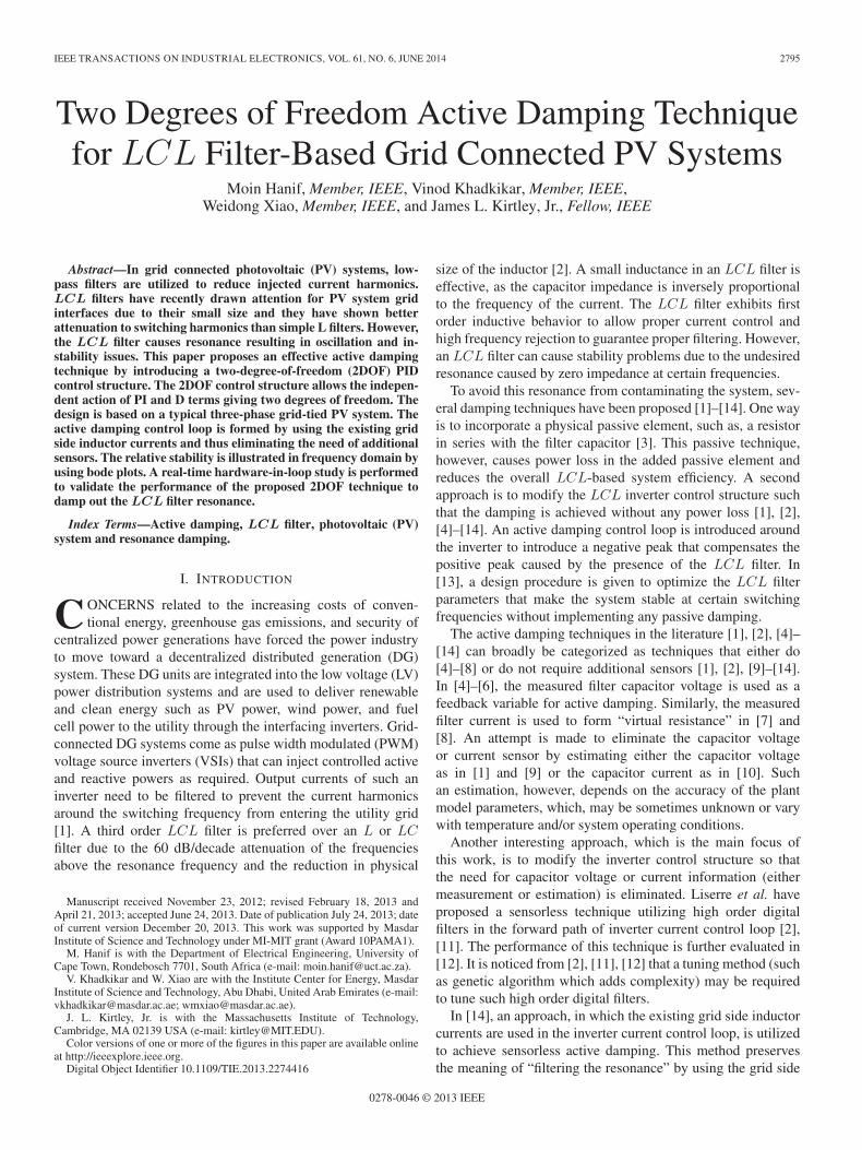
Fig. 1. Configuration of LCL filter based grid connected PV VSI.
inductor currents as feedback, and achieves active dampingsimply by modifying the inverter current control loop. However,as highlighted in [14], the proposed digital infinite impulseresponse (IIR) filter based sensorless active damping techniquehas the following challenges [14].
• It is based on a “true” digital control system with a fullZ-transform representation of the plant and the controller.In reality, the system comprising of inverter and LCL filterare analog in nature, therefore, the full digitalization is anapproximation process.
• Iterative optimization is required in [14] to meet the spec-ified design of the second order IIR Butterworth filterwhich increases the control complexity, the computingburden and also requires optimization expertise.
• In [14] the LCL damped system achieves a limited re-duction (68%) in the current oscillations compared to theundamped LCL system.
This paper proposes a two-degree-of-freedom (2DOF) PIDcontrol structure to achieve effective active damping for threephase grid-connected PV inverters. The proposed analysis usesthe existing grid side inductor currents and focuses on thesystem dynamics in continuous time. This 2DOF PID controlleris a general approach and can be easily tuned, using conven-tional techniques to obtain the required stability margin. Theproposed technique is validated both by simulation and a realtime hardware-in-loop (HIL) experimental study.
II. OVERALL SYSTEM CONFIGURATION
Fig. 1 shows the diagram of a three phase grid-tied PV powersystem, which adopts the dual stage conversion topology. TheLCL filter is the interface between the VSI and the pointof common coupling (PCC). For ac filtering analysis in adual stage PV system with a dc-dc converter (not shown inFig. 1), the dc side can be considered as a finite voltage source,therefore its dynamics are decoupled from the ac side.
Voltage-oriented control is adopted to control the PV invertersystems [1]–[3]. For unity power factor operation, the grid sideinductor current, ILg , is regulated to be a sinusoidal waveformand in-phase with the grid voltage. The detail control is dis-cussed later in Section V. Using the design guidelines from [15]and considering a maximum total harmonic distortion, THDof 5% at current output, the LCL parameters are chosen andshown in Table I (Appendix).
We define: f1, the fundamental frequency of the grid voltage;fres, resonance frequency; fc, controller sampling frequency
and fsw, switching frequency. The following design constraintsare considered [2].
• For good filtering performance: the resonance frequencyshould be in the range of 10f1 < fres < (fsw/2).
• The controller sampling frequency should be at least 2fsw.• Stability of the LCL filter is dependent on the ratio of
fres/fc. If the grid side inductor current is used for theinverter control, then the following relationship should bemaintained for a stable operation: (fres/fc) > (1/4) (i.e.,(fres/fsw) > (1/2)).
Since there is no alternative to achieve a good filteringperformance except by having fres < (fsw/2), the switchingfrequency, fsw is chosen such that it is about five times the filterresonance (≈5fres) for effective attenuation of higher ordercurrent harmonics. However, since fc is set to at least 2fsw, itcauses the ratio fres/fc to be less than 1/4, which, consequentlycauses resonance (instability). Therefore, the LCL filter reso-nance needs to be damped to achieve a stable operation.
III. UNDAMPED LCL FILTER BASED SYSTEM RESPONSE
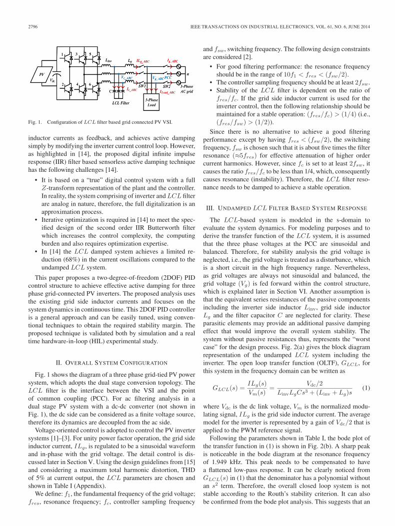
The LCL-based system is modeled in the s-domain toevaluate the system dynamics. For modeling purposes and toderive the transfer function of the LCL system, it is assumedthat the three phase voltages at the PCC are sinusoidal andbalanced. Therefore, for stability analysis the grid voltage isneglected, i.e., the grid voltage is treated as a disturbance, whichis a short circuit in the high frequency range. Nevertheless,as grid voltages are always not sinusoidal and balanced, thegrid voltage (Vg) is fed forward within the control structure,which is explained later in Section VI. Another assumption isthat the equivalent series resistances of the passive componentsincluding the inverter side inductor Linv, grid side inductorLg and the filter capacitor C are neglected for clarity. Theseparasitic elements may provide an additional passive dampingeffect that would improve the overall system stability. Thesystem without passive resistances thus, represents the “worstcase” for the design process. Fig. 2(a) gives the block diagramrepresentation of the undamped LCL system including theinverter. The open loop transfer function (OLTF), GLCL, forthis system in the frequency domain can be written as
GLCL(s) =ILg(s)
Vm(s)=
Vdc/2
LinvLgCs3 + (Linv + Lg)s(1)
where Vdc is the dc link voltage, Vm is the normalized modu-lating signal, ILg is the grid side inductor current. The averagemodel for the inverter is represented by a gain of Vdc/2 that isapplied to the PWM reference signal.
Following the parameters shown in Table I, the bode plot ofthe transfer function in (1) is shown in Fig. 2(b). A sharp peakis noticeable in the bode diagram at the resonance frequencyof 1.949 kHz. This peak needs to be compensated to havea flattened low-pass response. It can be clearly noticed fromGLCL(s) in (1) that the denominator has a polynomial withoutan s2 term. Therefore, the overall closed loop system is notstable according to the Routh’s stability criterion. It can alsobe confirmed from the bode plot analysis. This suggests that an
HANIF et al.: TWO DEGREES OF FREEDOM ACTIVE DAMPING TECHNIQUE 2797
Fig. 2. Block diagram and frequency response of undamped LCL filter basedgrid connected PV system. (a) Block (b) Bode plot.
additional damping term should be incorporated to stabilize thesystem.
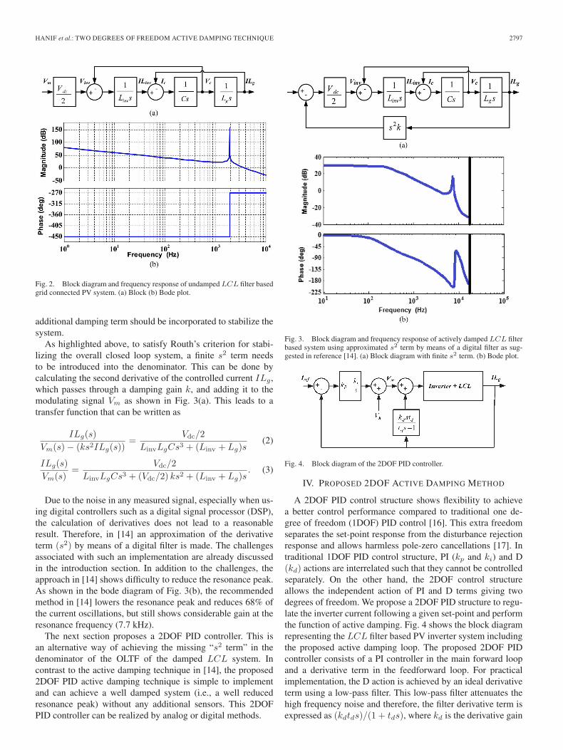
As highlighted above, to satisfy Routh’s criterion for stabi-lizing the overall closed loop system, a finite s2 term needsto be introduced into the denominator. This can be done bycalculating the second derivative of the controlled current ILg,which passes through a damping gain k, and adding it to themodulating signal Vm as shown in Fig. 3(a). This leads to atransfer function that can be written as
ILg(s)
Vm(s)− (ks2ILg(s))=
Vdc/2
LinvLgCs3 + (Linv + Lg)s(2)
ILg(s)
Vm(s)=
Vdc/2
LinvLgCs3 + (Vdc/2) ks2 + (Linv + Lg)s. (3)
Due to the noise in any measured signal, especially when us-ing digital controllers such as a digital signal processor (DSP),the calculation of derivatives does not lead to a reasonableresult. Therefore, in [14] an approximation of the derivativeterm (s2) by means of a digital filter is made. The challengesassociated with such an implementation are already discussedin the introduction section. In addition to the challenges, theapproach in [14] shows difficulty to reduce the resonance peak.As shown in the bode diagram of Fig. 3(b), the recommendedmethod in [14] lowers the resonance peak and reduces 68% ofthe current oscillations, but still shows considerable gain at theresonance frequency (7.7 kHz).
The next section proposes a 2DOF PID controller. This isan alternative way of achieving the missing “s2 term” in thedenominator of the OLTF of the damped LCL system. Incontrast to the active damping technique in [14], the proposed2DOF PID active damping technique is simple to implementand can achieve a well damped system (i.e., a well reducedresonance peak) without any additional sensors. This 2DOFPID controller can be realized by analog or digital methods.
Fig. 3. Block diagram and frequency response of actively damped LCL filterbased system using approximated s2 term by means of a digital filter as sug-gested in reference [14]. (a) Block diagram with finite s2 term. (b) Bode plot.
Fig. 4. Block diagram of the 2DOF PID controller.
IV. PROPOSED 2DOF ACTIVE DAMPING METHOD
A 2DOF PID control structure shows flexibility to achievea better control performance compared to traditional one de-gree of freedom (1DOF) PID control [16]. This extra freedomseparates the set-point response from the disturbance rejectionresponse and allows harmless pole-zero cancellations [17]. Intraditional 1DOF PID control structure, PI (kp and ki) and D(kd) actions are interrelated such that they cannot be controlledseparately. On the other hand, the 2DOF control structureallows the independent action of PI and D terms giving twodegrees of freedom. We propose a 2DOF PID structure to regu-late the inverter current following a given set-point and performthe function of active damping. Fig. 4 shows the block diagramrepresenting the LCL filter based PV inverter system includingthe proposed active damping loop. The proposed 2DOF PIDcontroller consists of a PI controller in the main forward loopand a derivative term in the feedforward loop. For practicalimplementation, the D action is achieved by an ideal derivativeterm using a low-pass filter. This low-pass filter attenuates thehigh frequency noise and therefore, the filter derivative term isexpressed as (kdtds)/(1 + tds), where kd is the derivative gain
2798 IEEE TRANSACTIONS ON INDUSTRIAL ELECTRONICS, VOL. 61, NO. 6, JUNE 2014
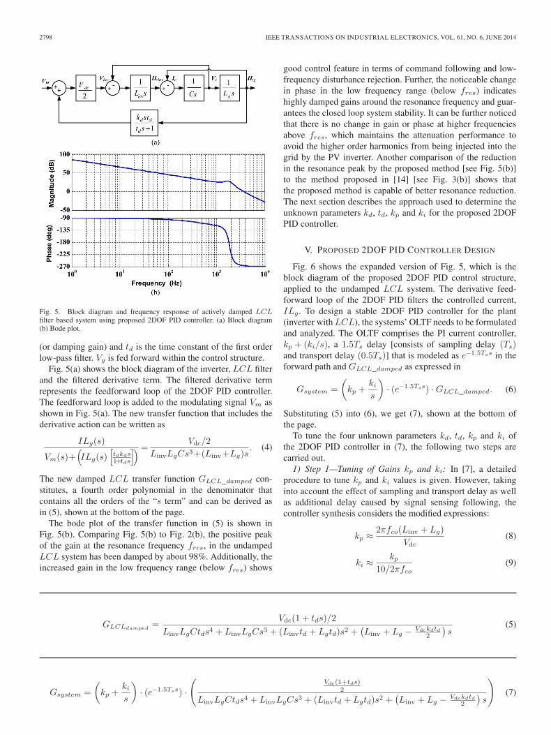
Fig. 5. Block diagram and frequency response of actively damped LCLfilter based system using proposed 2DOF PID controller. (a) Block diagram(b) Bode plot.
(or damping gain) and td is the time constant of the first orderlow-pass filter. Vg is fed forward within the control structure.
Fig. 5(a) shows the block diagram of the inverter, LCL filterand the filtered derivative term. The filtered derivative termrepresents the feedforward loop of the 2DOF PID controller.The feedforward loop is added to the modulating signal Vm asshown in Fig. 5(a). The new transfer function that includes thederivative action can be written as
ILg(s)
Vm(s)+(ILg(s)
[tdkds1+tds
])=Vdc/2
LinvLgCs3+(Linv+Lg)s. (4)
The new damped LCL transfer function GLCL_damped con-stitutes, a fourth order polynomial in the denominator thatcontains all the orders of the “s term” and can be derived asin (5), shown at the bottom of the page.
The bode plot of the transfer function in (5) is shown inFig. 5(b). Comparing Fig. 5(b) to Fig. 2(b), the positive peakof the gain at the resonance frequency fres, in the undampedLCL system has been damped by about 98%. Additionally, theincreased gain in the low frequency range (below fres) shows
good control feature in terms of command following and low-frequency disturbance rejection. Further, the noticeable changein phase in the low frequency range (below fres) indicateshighly damped gains around the resonance frequency and guar-antees the closed loop system stability. It can be further noticedthat there is no change in gain or phase at higher frequenciesabove fres, which maintains the attenuation performance toavoid the higher order harmonics from being injected into thegrid by the PV inverter. Another comparison of the reductionin the resonance peak by the proposed method [see Fig. 5(b)]to the method proposed in [14] [see Fig. 3(b)] shows thatthe proposed method is capable of better resonance reduction.The next section describes the approach used to determine theunknown parameters kd, td, kp and ki for the proposed 2DOFPID controller.
V. PROPOSED 2DOF PID CONTROLLER DESIGN
Fig. 6 shows the expanded version of Fig. 5, which is theblock diagram of the proposed 2DOF PID control structure,applied to the undamped LCL system. The derivative feed-forward loop of the 2DOF PID filters the controlled current,ILg . To design a stable 2DOF PID controller for the plant(inverter with LCL), the systems’ OLTF needs to be formulatedand analyzed. The OLTF comprises the PI current controller,kp + (ki/s), a 1.5Ts delay [consists of sampling delay (Ts)and transport delay (0.5Ts)] that is modeled as e−1.5Tss in theforward path and GLCL_damped as expressed in
Gsystem =
(kp +
kis
)· (e−1.5Tss) ·GLCL_damped. (6)
Substituting (5) into (6), we get (7), shown at the bottom ofthe page.
To tune the four unknown parameters kd, td, kp and ki ofthe 2DOF PID controller in (7), the following two steps arecarried out.
1) Step 1—Tuning of Gains kp and ki: In [7], a detailedprocedure to tune kp and ki values is given. However, takinginto account the effect of sampling and transport delay as wellas additional delay caused by signal sensing following, thecontroller synthesis considers the modified expressions:
kp ≈ 2πfco(Linv + Lg)
Vdc(8)
ki ≈kp
10/2πfco(9)
GLCLdamped=
Vdc(1 + tds)/2
LinvLgCtds4 + LinvLgCs3 + (Linvtd + Lgtd)s2 +(Linv + Lg − Vdckdtd
2
)s
(5)
Gsystem =
(kp +
kis
)· (e−1.5Tss) ·
(Vdc(1+tds)
2
LinvLgCtds4 + LinvLgCs3 + (Linvtd + Lgtd)s2 +(Linv + Lg − Vdckdtd
2
)s
)(7)
HANIF et al.: TWO DEGREES OF FREEDOM ACTIVE DAMPING TECHNIQUE 2799
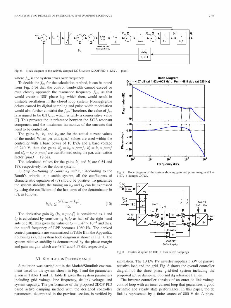
Fig. 6. Block diagram of the actively damped LCL system (2DOF PID + 1.5Ts + plant).
where fco is the system cross over frequency.To decide the fco for the calculation method, it can be noted
from Fig. 5(b) that the control bandwidth cannot exceed oreven closely approach the resonance frequency fres as thatwould create a 180◦ phase lag, which then, would result inunstable oscillation in the closed loop system. Nonnegligibledelays caused by digital sampling and pulse width modulationwould also further constrict the fco. Therefore, the value of fcois assigned to be 0.3fres, which is fairly a conservative value[7]. This prevents the interference between the LCL resonantcomponent and the maximum harmonics of the currents thatneed to be controlled.
The gains kp, ki, and kd are for the actual current valuesof the model. When per unit (p.u.) values are used within thecontroller with a base power of 10 kVA and a base voltageof 240 V, then the gains k′p = kp × puaf , k′i = ki × puafand k′d = kd × puaf are transformed using the p.u. attenuationfactor (puaf = 19.64).
The calculated values for the gains k′p and k′i are 0.54 and198, respectively, for the above system.
2) Step 2—Tuning of Gains kd and td: According to theRouth’s criteria, in a stable system, all the coefficients ofcharacteristic equation of (7) should be positive. To guaranteethe system stability, the tuning on kd and td can be expressedby using the coefficient of the last term of the denominator in(7), as follows:
kdtd ≤ 2(Linv + Lg)
Vdc. (10)
The derivative gain k′d (kd × puaf) is considered as 1 andtd is calculated by considering kdtd as half of the right handside of (10). This gives the value of td = 1.47× 10⁻⁴ and thus,the cutoff frequency of LPF becomes 1080 Hz. The derivedcontrol parameters are summarized in Table II in the Appendix.Following (7), the system bode diagram is shown in Fig. 7. Thesystem relative stability is demonstrated by the phase marginand gain margin, which are 48.9◦ and 4.57 dB, respectively.
VI. SIMULATION PERFORMANCE
Simulation was carried out in the Matlab/Simulink environ-ment based on the system shown in Fig. 1 and the parametersgiven in Tables I and II. Table II gives the system parametersincluding grid voltage, line frequency, dc link voltage, andsystem capacity. The performance of the proposed 2DOF PIDbased active damping method with the designed controllerparameters, determined in the previous section, is verified by
Fig. 7. Bode diagram of the system showing gain and phase margins (PI +1.5Ts + damped LCL).
Fig. 8. Control diagram (2DOF PID for active damping).
simulation. The 10 kW PV inverter supplies 5 kW of passiveresistive load and the grid. Fig. 8 shows the overall controllerdiagram of the three phase grid-tied system including theproposed active damping loop and dq reference frames.
The inverter controller consists of an outer dc link voltagecontrol loop with an inner current loop that guarantees a gooddynamic and steady state performance. In this paper, the dclink is represented by a finite source of 800 V dc. A phase
2800 IEEE TRANSACTIONS ON INDUSTRIAL ELECTRONICS, VOL. 61, NO. 6, JUNE 2014
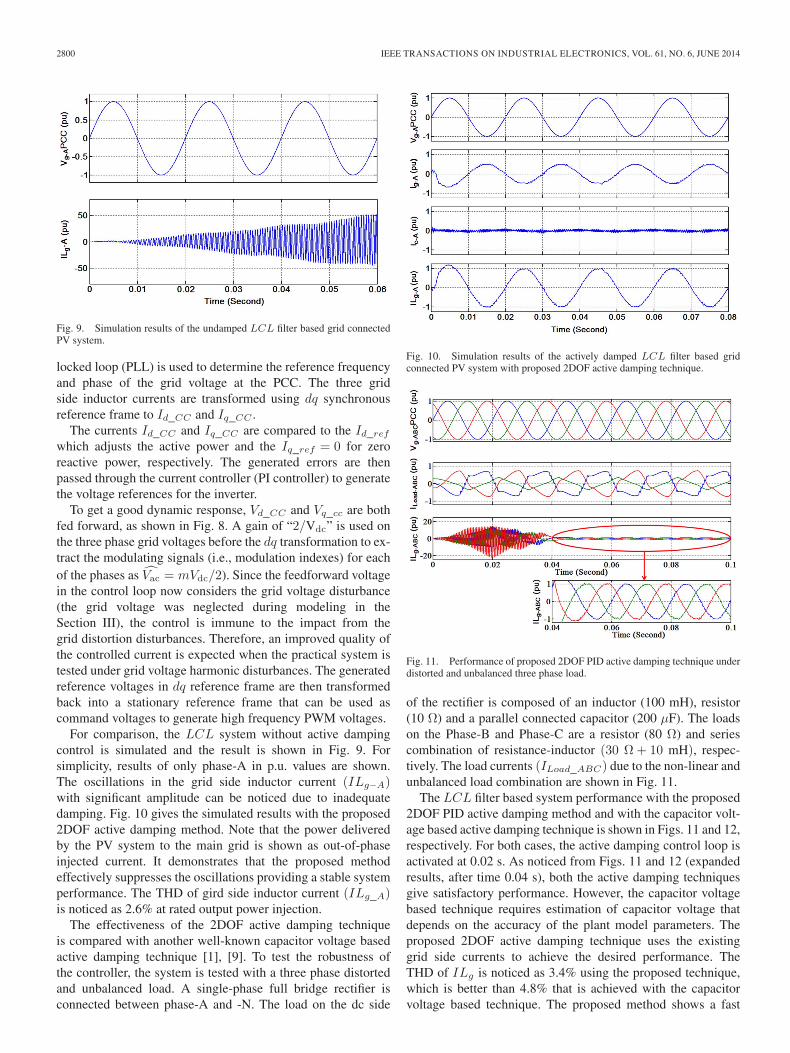
Fig. 9. Simulation results of the undamped LCL filter based grid connectedPV system.
locked loop (PLL) is used to determine the reference frequencyand phase of the grid voltage at the PCC. The three gridside inductor currents are transformed using dq synchronousreference frame to Id_CC and Iq_CC .
The currents Id_CC and Iq_CC are compared to the Id_refwhich adjusts the active power and the Iq_ref = 0 for zeroreactive power, respectively. The generated errors are thenpassed through the current controller (PI controller) to generatethe voltage references for the inverter.
To get a good dynamic response, Vd_CC and Vq_cc are bothfed forward, as shown in Fig. 8. A gain of “2/Vdc” is used onthe three phase grid voltages before the dq transformation to ex-tract the modulating signals (i.e., modulation indexes) for eachof the phases as V̂ac = mVdc/2). Since the feedforward voltagein the control loop now considers the grid voltage disturbance(the grid voltage was neglected during modeling in theSection III), the control is immune to the impact from thegrid distortion disturbances. Therefore, an improved quality ofthe controlled current is expected when the practical system istested under grid voltage harmonic disturbances. The generatedreference voltages in dq reference frame are then transformedback into a stationary reference frame that can be used ascommand voltages to generate high frequency PWM voltages.
For comparison, the LCL system without active dampingcontrol is simulated and the result is shown in Fig. 9. Forsimplicity, results of only phase-A in p.u. values are shown.The oscillations in the grid side inductor current (ILg−A)with significant amplitude can be noticed due to inadequatedamping. Fig. 10 gives the simulated results with the proposed2DOF active damping method. Note that the power deliveredby the PV system to the main grid is shown as out-of-phaseinjected current. It demonstrates that the proposed methodeffectively suppresses the oscillations providing a stable systemperformance. The THD of gird side inductor current (ILg_A)is noticed as 2.6% at rated output power injection.
The effectiveness of the 2DOF active damping techniqueis compared with another well-known capacitor voltage basedactive damping technique [1], [9]. To test the robustness ofthe controller, the system is tested with a three phase distortedand unbalanced load. A single-phase full bridge rectifier isconnected between phase-A and -N. The load on the dc side
Fig. 10. Simulation results of the actively damped LCL filter based gridconnected PV system with proposed 2DOF active damping technique.
Fig. 11. Performance of proposed 2DOF PID active damping technique underdistorted and unbalanced three phase load.
of the rectifier is composed of an inductor (100 mH), resistor(10 Ω) and a parallel connected capacitor (200 μF). The loadson the Phase-B and Phase-C are a resistor (80 Ω) and seriescombination of resistance-inductor (30 Ω + 10 mH), respec-tively. The load currents (ILoad_ABC) due to the non-linear andunbalanced load combination are shown in Fig. 11.
The LCL filter based system performance with the proposed2DOF PID active damping method and with the capacitor volt-age based active damping technique is shown in Figs. 11 and 12,respectively. For both cases, the active damping control loop isactivated at 0.02 s. As noticed from Figs. 11 and 12 (expandedresults, after time 0.04 s), both the active damping techniquesgive satisfactory performance. However, the capacitor voltagebased technique requires estimation of capacitor voltage thatdepends on the accuracy of the plant model parameters. Theproposed 2DOF active damping technique uses the existinggrid side currents to achieve the desired performance. TheTHD of ILg is noticed as 3.4% using the proposed technique,which is better than 4.8% that is achieved with the capacitorvoltage based technique. The proposed method shows a fast
HANIF et al.: TWO DEGREES OF FREEDOM ACTIVE DAMPING TECHNIQUE 2801
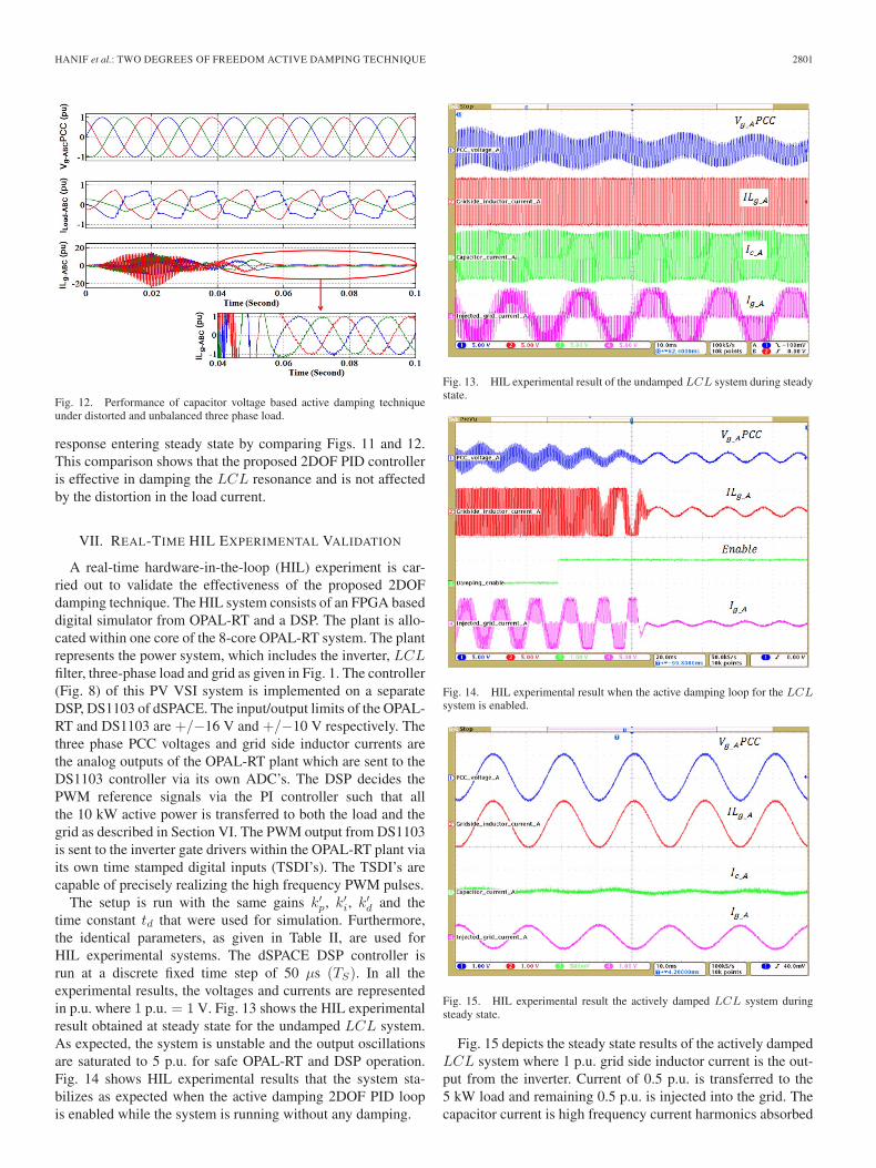
Fig. 12. Performance of capacitor voltage based active damping techniqueunder distorted and unbalanced three phase load.
response entering steady state by comparing Figs. 11 and 12.This comparison shows that the proposed 2DOF PID controlleris effective in damping the LCL resonance and is not affectedby the distortion in the load current.
VII. REAL-TIME HIL EXPERIMENTAL VALIDATION
A real-time hardware-in-the-loop (HIL) experiment is car-ried out to validate the effectiveness of the proposed 2DOFdamping technique. The HIL system consists of an FPGA baseddigital simulator from OPAL-RT and a DSP. The plant is allo-cated within one core of the 8-core OPAL-RT system. The plantrepresents the power system, which includes the inverter, LCLfilter, three-phase load and grid as given in Fig. 1. The controller(Fig. 8) of this PV VSI system is implemented on a separateDSP, DS1103 of dSPACE. The input/output limits of the OPAL-RT and DS1103 are +/−16 V and +/−10 V respectively. Thethree phase PCC voltages and grid side inductor currents arethe analog outputs of the OPAL-RT plant which are sent to theDS1103 controller via its own ADC’s. The DSP decides thePWM reference signals via the PI controller such that allthe 10 kW active power is transferred to both the load and thegrid as described in Section VI. The PWM output from DS1103is sent to the inverter gate drivers within the OPAL-RT plant viaits own time stamped digital inputs (TSDI’s). The TSDI’s arecapable of precisely realizing the high frequency PWM pulses.
The setup is run with the same gains k′p, k′i, k′d and thetime constant td that were used for simulation. Furthermore,the identical parameters, as given in Table II, are used forHIL experimental systems. The dSPACE DSP controller isrun at a discrete fixed time step of 50 μs (TS). In all theexperimental results, the voltages and currents are representedin p.u. where 1 p.u. = 1 V. Fig. 13 shows the HIL experimentalresult obtained at steady state for the undamped LCL system.As expected, the system is unstable and the output oscillationsare saturated to 5 p.u. for safe OPAL-RT and DSP operation.Fig. 14 shows HIL experimental results that the system sta-bilizes as expected when the active damping 2DOF PID loopis enabled while the system is running without any damping.
Fig. 13. HIL experimental result of the undamped LCL system during steadystate.
Fig. 14. HIL experimental result when the active damping loop for the LCLsystem is enabled.
Fig. 15. HIL experimental result the actively damped LCL system duringsteady state.
Fig. 15 depicts the steady state results of the actively dampedLCL system where 1 p.u. grid side inductor current is the out-put from the inverter. Current of 0.5 p.u. is transferred to the5 kW load and remaining 0.5 p.u. is injected into the grid. Thecapacitor current is high frequency current harmonics absorbed
2802 IEEE TRANSACTIONS ON INDUSTRIAL ELECTRONICS, VOL. 61, NO. 6, JUNE 2014
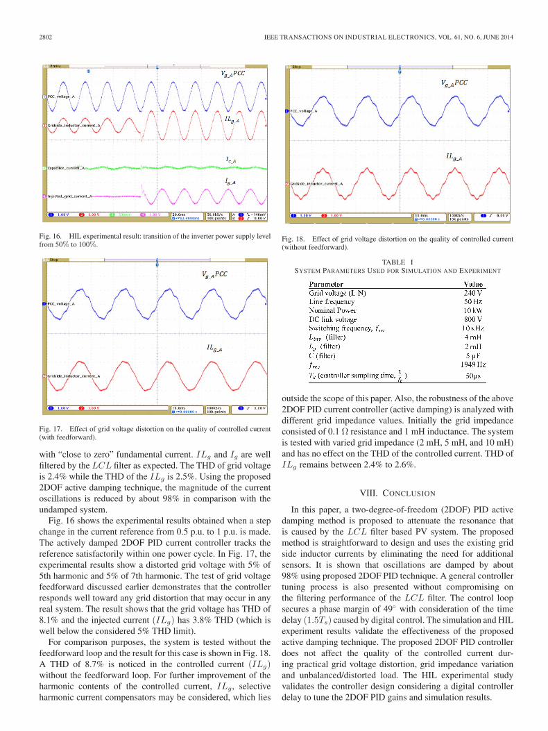
Fig. 16. HIL experimental result: transition of the inverter power supply levelfrom 50% to 100%.
Fig. 17. Effect of grid voltage distortion on the quality of controlled current(with feedforward).
with “close to zero” fundamental current. ILg and Ig are wellfiltered by the LCL filter as expected. The THD of grid voltageis 2.4% while the THD of the ILg is 2.5%. Using the proposed2DOF active damping technique, the magnitude of the currentoscillations is reduced by about 98% in comparison with theundamped system.
Fig. 16 shows the experimental results obtained when a stepchange in the current reference from 0.5 p.u. to 1 p.u. is made.The actively damped 2DOF PID current controller tracks thereference satisfactorily within one power cycle. In Fig. 17, theexperimental results show a distorted grid voltage with 5% of5th harmonic and 5% of 7th harmonic. The test of grid voltagefeedforward discussed earlier demonstrates that the controllerresponds well toward any grid distortion that may occur in anyreal system. The result shows that the grid voltage has THD of8.1% and the injected current (ILg) has 3.8% THD (which iswell below the considered 5% THD limit).
For comparison purposes, the system is tested without thefeedforward loop and the result for this case is shown in Fig. 18.A THD of 8.7% is noticed in the controlled current (ILg)without the feedforward loop. For further improvement of theharmonic contents of the controlled current, ILg , selectiveharmonic current compensators may be considered, which lies
Fig. 18. Effect of grid voltage distortion on the quality of controlled current(without feedforward).
TABLE ISYSTEM PARAMETERS USED FOR SIMULATION AND EXPERIMENT
outside the scope of this paper. Also, the robustness of the above2DOF PID current controller (active damping) is analyzed withdifferent grid impedance values. Initially the grid impedanceconsisted of 0.1 Ω resistance and 1 mH inductance. The systemis tested with varied grid impedance (2 mH, 5 mH, and 10 mH)and has no effect on the THD of the controlled current. THD ofILg remains between 2.4% to 2.6%.
VIII. CONCLUSION
In this paper, a two-degree-of-freedom (2DOF) PID activedamping method is proposed to attenuate the resonance thatis caused by the LCL filter based PV system. The proposedmethod is straightforward to design and uses the existing gridside inductor currents by eliminating the need for additionalsensors. It is shown that oscillations are damped by about98% using proposed 2DOF PID technique. A general controllertuning process is also presented without compromising onthe filtering performance of the LCL filter. The control loopsecures a phase margin of 49◦ with consideration of the timedelay (1.5Ts) caused by digital control. The simulation and HILexperiment results validate the effectiveness of the proposedactive damping technique. The proposed 2DOF PID controllerdoes not affect the quality of the controlled current dur-ing practical grid voltage distortion, grid impedance variationand unbalanced/distorted load. The HIL experimental studyvalidates the controller design considering a digital controllerdelay to tune the 2DOF PID gains and simulation results.
HANIF et al.: TWO DEGREES OF FREEDOM ACTIVE DAMPING TECHNIQUE 2803
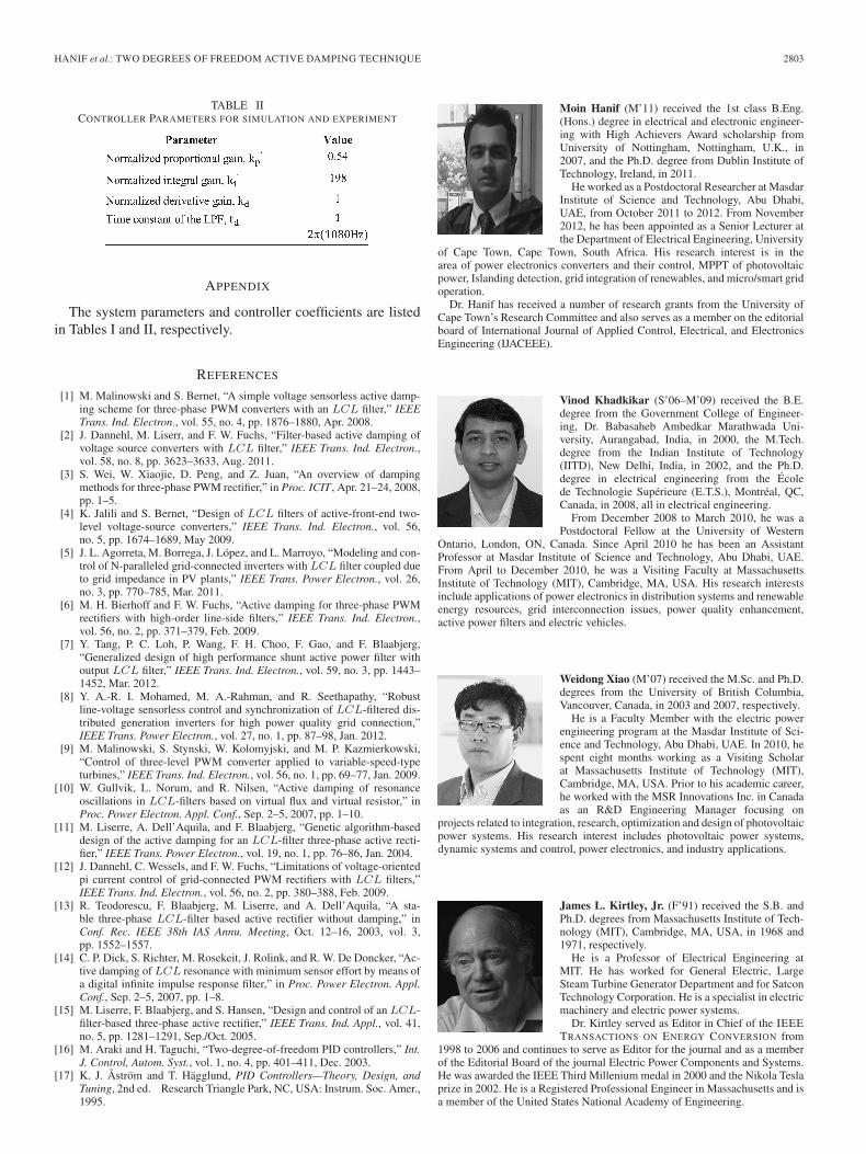
TABLE IICONTROLLER PARAMETERS FOR SIMULATION AND EXPERIMENT
APPENDIX
The system parameters and controller coefficients are listedin Tables I and II, respectively.
REFERENCES
[1] M. Malinowski and S. Bernet, “A simple voltage sensorless active damp-ing scheme for three-phase PWM converters with an LCL filter,” IEEETrans. Ind. Electron., vol. 55, no. 4, pp. 1876–1880, Apr. 2008.
[2] J. Dannehl, M. Liserr, and F. W. Fuchs, “Filter-based active damping ofvoltage source converters with LCL filter,” IEEE Trans. Ind. Electron.,vol. 58, no. 8, pp. 3623–3633, Aug. 2011.
[3] S. Wei, W. Xiaojie, D. Peng, and Z. Juan, “An overview of dampingmethods for three-phase PWM rectifier,” in Proc. ICIT , Apr. 21–24, 2008,pp. 1–5.
[4] K. Jalili and S. Bernet, “Design of LCL filters of active-front-end two-level voltage-source converters,” IEEE Trans. Ind. Electron., vol. 56,no. 5, pp. 1674–1689, May 2009.
[5] J. L. Agorreta, M. Borrega, J. López, and L. Marroyo, “Modeling and con-trol of N-paralleled grid-connected inverters with LCL filter coupled dueto grid impedance in PV plants,” IEEE Trans. Power Electron., vol. 26,no. 3, pp. 770–785, Mar. 2011.
[6] M. H. Bierhoff and F. W. Fuchs, “Active damping for three-phase PWMrectifiers with high-order line-side filters,” IEEE Trans. Ind. Electron.,vol. 56, no. 2, pp. 371–379, Feb. 2009.
[7] Y. Tang, P. C. Loh, P. Wang, F. H. Choo, F. Gao, and F. Blaabjerg,“Generalized design of high performance shunt active power filter withoutput LCL filter,” IEEE Trans. Ind. Electron., vol. 59, no. 3, pp. 1443–1452, Mar. 2012.
[8] Y. A.-R. I. Mohamed, M. A.-Rahman, and R. Seethapathy, “Robustline-voltage sensorless control and synchronization of LCL-filtered dis-tributed generation inverters for high power quality grid connection,”IEEE Trans. Power Electron., vol. 27, no. 1, pp. 87–98, Jan. 2012.
[9] M. Malinowski, S. Stynski, W. Kolomyjski, and M. P. Kazmierkowski,“Control of three-level PWM converter applied to variable-speed-typeturbines,” IEEE Trans. Ind. Electron., vol. 56, no. 1, pp. 69–77, Jan. 2009.
[10] W. Gullvik, L. Norum, and R. Nilsen, “Active damping of resonanceoscillations in LCL-filters based on virtual flux and virtual resistor,” inProc. Power Electron. Appl. Conf., Sep. 2–5, 2007, pp. 1–10.
[11] M. Liserre, A. Dell’Aquila, and F. Blaabjerg, “Genetic algorithm-baseddesign of the active damping for an LCL-filter three-phase active recti-fier,” IEEE Trans. Power Electron., vol. 19, no. 1, pp. 76–86, Jan. 2004.
[12] J. Dannehl, C. Wessels, and F. W. Fuchs, “Limitations of voltage-orientedpi current control of grid-connected PWM rectifiers with LCL filters,”IEEE Trans. Ind. Electron., vol. 56, no. 2, pp. 380–388, Feb. 2009.
[13] R. Teodorescu, F. Blaabjerg, M. Liserre, and A. Dell’Aquila, “A sta-ble three-phase LCL-filter based active rectifier without damping,” inConf. Rec. IEEE 38th IAS Annu. Meeting, Oct. 12–16, 2003, vol. 3,pp. 1552–1557.
[14] C. P. Dick, S. Richter, M. Rosekeit, J. Rolink, and R. W. De Doncker, “Ac-tive damping of LCL resonance with minimum sensor effort by means ofa digital infinite impulse response filter,” in Proc. Power Electron. Appl.Conf., Sep. 2–5, 2007, pp. 1–8.
[15] M. Liserre, F. Blaabjerg, and S. Hansen, “Design and control of an LCL-filter-based three-phase active rectifier,” IEEE Trans. Ind. Appl., vol. 41,no. 5, pp. 1281–1291, Sep./Oct. 2005.
[16] M. Araki and H. Taguchi, “Two-degree-of-freedom PID controllers,” Int.J. Control, Autom. Syst., vol. 1, no. 4, pp. 401–411, Dec. 2003.
[17] K. J. Åström and T. Hägglund, PID Controllers—Theory, Design, andTuning, 2nd ed. Research Triangle Park, NC, USA: Instrum. Soc. Amer.,1995.
Moin Hanif (M’11) received the 1st class B.Eng.(Hons.) degree in electrical and electronic engineer-ing with High Achievers Award scholarship fromUniversity of Nottingham, Nottingham, U.K., in2007, and the Ph.D. degree from Dublin Institute ofTechnology, Ireland, in 2011.
He worked as a Postdoctoral Researcher at MasdarInstitute of Science and Technology, Abu Dhabi,UAE, from October 2011 to 2012. From November2012, he has been appointed as a Senior Lecturer atthe Department of Electrical Engineering, University
of Cape Town, Cape Town, South Africa. His research interest is in thearea of power electronics converters and their control, MPPT of photovoltaicpower, Islanding detection, grid integration of renewables, and micro/smart gridoperation.
Dr. Hanif has received a number of research grants from the University ofCape Town’s Research Committee and also serves as a member on the editorialboard of International Journal of Applied Control, Electrical, and ElectronicsEngineering (IJACEEE).
Vinod Khadkikar (S’06–M’09) received the B.E.degree from the Government College of Engineer-ing, Dr. Babasaheb Ambedkar Marathwada Uni-versity, Aurangabad, India, in 2000, the M.Tech.degree from the Indian Institute of Technology(IITD), New Delhi, India, in 2002, and the Ph.D.degree in electrical engineering from the Écolede Technologie Supérieure (E.T.S.), Montréal, QC,Canada, in 2008, all in electrical engineering.
From December 2008 to March 2010, he was aPostdoctoral Fellow at the University of Western
Ontario, London, ON, Canada. Since April 2010 he has been an AssistantProfessor at Masdar Institute of Science and Technology, Abu Dhabi, UAE.From April to December 2010, he was a Visiting Faculty at MassachusettsInstitute of Technology (MIT), Cambridge, MA, USA. His research interestsinclude applications of power electronics in distribution systems and renewableenergy resources, grid interconnection issues, power quality enhancement,active power filters and electric vehicles.
Weidong Xiao (M’07) received the M.Sc. and Ph.D.degrees from the University of British Columbia,Vancouver, Canada, in 2003 and 2007, respectively.
He is a Faculty Member with the electric powerengineering program at the Masdar Institute of Sci-ence and Technology, Abu Dhabi, UAE. In 2010, hespent eight months working as a Visiting Scholarat Massachusetts Institute of Technology (MIT),Cambridge, MA, USA. Prior to his academic career,he worked with the MSR Innovations Inc. in Canadaas an R&D Engineering Manager focusing on
projects related to integration, research, optimization and design of photovoltaicpower systems. His research interest includes photovoltaic power systems,dynamic systems and control, power electronics, and industry applications.
James L. Kirtley, Jr. (F’91) received the S.B. andPh.D. degrees from Massachusetts Institute of Tech-nology (MIT), Cambridge, MA, USA, in 1968 and1971, respectively.
He is a Professor of Electrical Engineering atMIT. He has worked for General Electric, LargeSteam Turbine Generator Department and for SatconTechnology Corporation. He is a specialist in electricmachinery and electric power systems.
Dr. Kirtley served as Editor in Chief of the IEEETRANSACTIONS ON ENERGY CONVERSION from
1998 to 2006 and continues to serve as Editor for the journal and as a memberof the Editorial Board of the journal Electric Power Components and Systems.He was awarded the IEEE Third Millenium medal in 2000 and the Nikola Teslaprize in 2002. He is a Registered Professional Engineer in Massachusetts and isa member of the United States National Academy of Engineering.


