Embed Size (px)
Citation preview
507
Publication, traduction et reproduction totales ou partielles de ce document sont rigoureusement interdites sauf autorisation écrite de nos services.
The publication, translation and reproduction, either wholly or partly, of this document are not allowed without our written consent.
Industrial electrical network design guide T & D 6 883 427/AE
6. Determining conductor cross-
sectional areas
508
Publication, traduction et reproduction totales ou partielles de ce document sont rigoureusement interdites sauf autorisation écrite de nos services.
The publication, translation and reproduction, either wholly or partly, of this document are not allowed without our written consent.
Industrial electrical network design guide T & D 6 883 427/AE
6. DETERMINING CONDUCTOR CROSS-SECTIONAL AREAS
Owing to the respective characteristics of LV and MV conductors, they have been dealt with in
separate paragraphs.
6.1. Determining conductor cross-sectional areas and choosing protective
devices in low voltage
n definition of terms relating to low voltage wiring systems
(Insulated) cable
Assembly comprising:
- one or more insulated conductors
- their eventual individual screening
- any eventual assembly protection
- any eventual protective shielding
It may also comprise one or several bare conductors.
Multi-core cable
Cable comprising more than one conductor, which may eventually include bare conductors.
Note: the term three-core cable is used to designate the cable making up the phases of a three-phase
system.
Single-core cable
Cable comprising a single insulated conductor.
Note: the term single-core cable is especially used to designate a cable making up one of the phases of a
three-phase system.
Wiring system
Assembly made up of one or more electric conductors and the devices ensuring their fixation and, if
necessary, their mechanical protection.
Cable channel
Ventilated or enclosed duct located above or in the ground, having dimensions preventing persons from
moving around inside it but allowing access to the cables over their entire length during and after
installation.
Note: a cable channel may or may not form part of the building construction.
Cable tray
Holder made up of a base and sides but no cover.
Note: A cable tray may be perforated or unperforated.
Electrical circuit (of an installation)
All the electrical equipment of the installation fed from the same source and protected against
overcurrents by the same protective device(s).

509
Publication, traduction et reproduction totales ou partielles de ce document sont rigoureusement interdites sauf autorisation écrite de nos services.
The publication, translation and reproduction, either wholly or partly, of this document are not allowed without our written consent.
Industrial electrical network design guide T & D 6 883 427/AE
(Insulated) conductor
Assembly comprising the conductor, its insulating envelope and eventual screens.
(Circular) conduit
Enclosed envelope, having a circular cross-section, designed for the installation or the replacement of
insulated conductors or cables by capstan, in electrical installations.
Ducting
Assembly of closed envelopes having a non circular cross-sectional area, designed for the installation or
the replacement of insulated conductors or cables by capstan, in electrical installations.
Brackets
Horizontal cable supports fixed at one of their ends, arranged from point to point and on which the cables
rest.
Design current of a circuit
Current to be carried in a circuit in normal service
(Continuous) current carrying capacity of a conductor
Maximum value of the current that, in given conditions, can continuously flow in a conductor without its
steady-state operating temperature being higher than the specified value.
Cable ladder
Cable support made up of a series of non-touching elements firmly fixed to main vertical rods.
Sleeve (or tube)
Element surrounding wiring and providing it with extra protection in building passages (walls, partitions,
floor, ceiling) or in buried passages.
Sheath
Enclosure located above ground level having dimensions preventing persons from moving around inside
it but allowing access to the cables over their entire length. A sheath may or may not be built into the
masonry.
Trough
Assembly of envelopes closed by a cover and ensuring mechanical protection of insulated conductors or
cables not installed or removed by a capstan and which allow other electrical equipment to be added .
Building void
Space in a structure or building parts which is only accessible at certain places.
Note: - spaces in walls, supported floors, ceilings and certain types of window or door frames and
jamb linings are examples of building voids.
- specially built building voids are also called "ducts".
510
Publication, traduction et reproduction totales ou partielles de ce document sont rigoureusement interdites sauf autorisation écrite de nos services.
The publication, translation and reproduction, either wholly or partly, of this document are not allowed without our written consent.
Industrial electrical network design guide T & D 6 883 427/AE
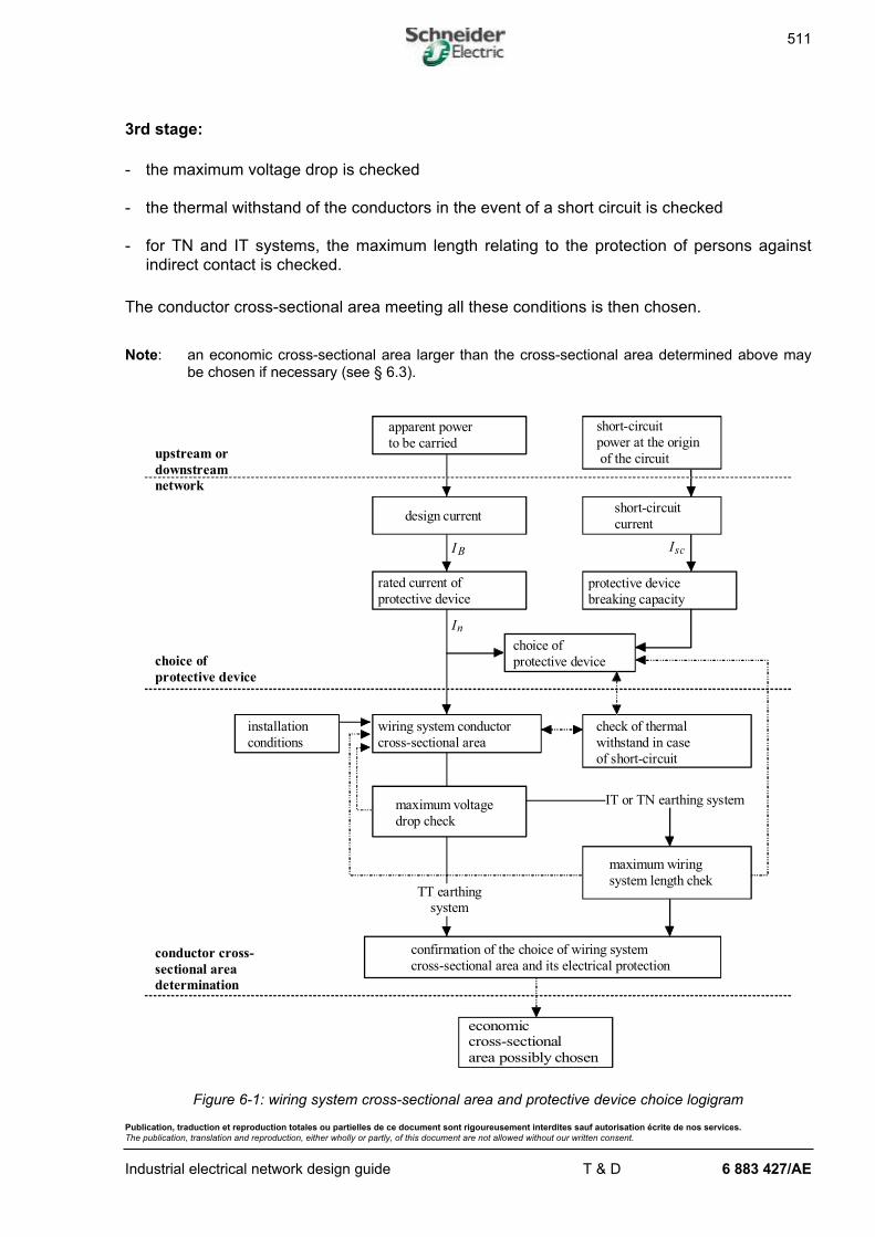
6.1.1. Method principle
In compliance with the recommendations of IEC 364-4-43, the cross-sectional area of wiring
systems and the protective device must be chosen to meet several conditions necessary for
the security of the installation.
The wiring system must:
- carry the maximum design current and its normal transient peaks
- not generate voltage drops above the allowed values.
The protective device must:
- protect the wiring system against any overcurrents up to the short-circuit current
- ensure the protection of persons against indirect contact.
The logigram in figure 6-1 sums up the principle of the method which may be described by the
following stages:
1st stage:
- using the load power, the maximum design current IB is calculated and the rated current
In of the protective device is deduced from this
- the maximum short-circuit current Isc at the origin of the circuit is calculated and the
breaking capacity of the protective device is deduced from this.
2nd stage:
- depending on the installation conditions (installation method, ambient temperature, etc.),
the overall correction factor f is determined
- the suitable conductor cross-sectional area is chosen in relation to In and f .
511
Publication, traduction et reproduction totales ou partielles de ce document sont rigoureusement interdites sauf autorisation écrite de nos services.
The publication, translation and reproduction, either wholly or partly, of this document are not allowed without our written consent.
Industrial electrical network design guide T & D 6 883 427/AE
3rd stage:
- the maximum voltage drop is checked
- the thermal withstand of the conductors in the event of a short circuit is checked
- for TN and IT systems, the maximum length relating to the protection of persons against
indirect contact is checked.
The conductor cross-sectional area meeting all these conditions is then chosen.
Note: an economic cross-sectional area larger than the cross-sectional area determined above maybe chosen if necessary (see § 6.3).
maximumwiring
system length chek
apparent power
to be carried
short-circuit
power at the origin
of the circuit
design currentshort-circuit
current
rated current of
protective deviceprotective device
breaking capacity
wiring system conductor
cross-sectional area
check of thermal
withstand in case
of short-circuit
maximumvoltage
drop check
confirmation of the choice of wiring system
cross-sectional area and its electrical protection
economiccross-sectional
area possibly chosen
installation
conditions
IT or TN earthing system
choice of
protective device
TT earthingsystem
upstream or
downstream
network
choice of
protective device
conductor cross-
sectional area
determination
In
IB Isc
Figure 6-1: wiring system cross-sectional area and protective device choice logigram
512
Publication, traduction et reproduction totales ou partielles de ce document sont rigoureusement interdites sauf autorisation écrite de nos services.
The publication, translation and reproduction, either wholly or partly, of this document are not allowed without our written consent.
Industrial electrical network design guide T & D 6 883 427/AE
6.1.2. Determining the maximum design current
The maximum design current ( IB ) is defined according to the type of installation fed by the
wiring system.
In the case of individual power supply to a device, the current IB will be equal to the rated
current of the device being fed. On the other hand, if the wiring system feeds several devices,
the current IB will be equal to the sum of currents absorbed, taking into account the
installation utilisation and coincidence factors.
In the case of motor starting or cyclical operating conditions of loads (spot welding station,
see § 3.4.2), current inrushes must be taken into account when their thermal effects are
cumulated.
Some installations are subject to future extensions. The current corresponding to this
extension will be added to the existing value.
In direct current: IP
U
power consumed in W
duty voltage in V=
( )
( )
In alternating current: IS
U= in single-phase and I
S
U=
3 in three-phase.
S : apparent power consumed (VA)
U : . voltage between the two conductors for a single-phase power supply
. phase-to-phase voltage for a three-phase power supply
When high harmonic currents circulate in the conductor, they must be taken into account. In
order to choose the cross-sectional area, the following must therefore be taken:
I Ir m s p
p
. . . =
=
∞
∑ 2
1
1
(see § 8)
I1 : current value at 50 Hz (or 60 Hz)
I p : value of harmonic current of order p
For example, for a speed variatorI
I
r m s. . . .1
1 7≅
When there are compensation capacitors downstream of the wiring system, the design current
is determined as follows:
- assuming that compensation is in operation: in case of failure of the capacitors, the wiring
system is placed out of service
- assuming that compensation is out of service; in case of failure of the capacitors, the
conductor cross-sectional area is sufficient and availability is thus improved.
513
Publication, traduction et reproduction totales ou partielles de ce document sont rigoureusement interdites sauf autorisation écrite de nos services.
The publication, translation and reproduction, either wholly or partly, of this document are not allowed without our written consent.
Industrial electrical network design guide T & D 6 883 427/AE
n factor taking into account the power factor and efficiency: a
The apparent power of a load is:
SP
Fp
=×η
in kVA
P : active power in kW
η : efficiency
Fp : power factor
We define the coefficient: aFp
=×1
η
When a current stripped of harmonics flows through the conductor, Fp = cosϕ .
n load utilisation factor: b
In an industrial installation, it is assumed that loads will never be used at their full power level.
A utilisation factor ( b ) is therefore introduced which generally varies from 0.3 to 1.
Without knowing the accurate values, we may take:
- b = 0 75. for motors
- b =1 for lighting and heating
514
Publication, traduction et reproduction totales ou partielles de ce document sont rigoureusement interdites sauf autorisation écrite de nos services.
The publication, translation and reproduction, either wholly or partly, of this document are not allowed without our written consent.
Industrial electrical network design guide T & D 6 883 427/AE
n coincidence factor: c
In an industrial installation, the loads (of a workshop, for example) fed by the same wiring
system do not operate simultaneously in all cases. To take this phenomenon, which is linked to
the operating conditions of the installation, into account, the coincidence factor is applied to
the sum of the load powers in conductor sizing.
In the absence of precise indications resulting from experience of standard installations, the
values of tables 6-1 et 6-2 may be applied:
Use Coincidence factor c
Lighting 1
Lighting and air conditioning 1
Power outlets 0.1 to 0.2 (for a number > 20)
Table 6-1: coincidence factor for an administrative building
Number of circuits having
similar nominal currents
Coincidence factor
2 and 3 0.9
4 and 5 0.8
5 to 9 0.7
10 and more 0.6
Table 6-2: coincidence factor for industrial distribution switchboards
n factor taking into account possible future extensions: d
The value of factor d must be estimated according to the foreseeable extensions of the
installation.
In the absence of precise indications, the value 1.2 is often used.
515
Publication, traduction et reproduction totales ou partielles de ce document sont rigoureusement interdites sauf autorisation écrite de nos services.
The publication, translation and reproduction, either wholly or partly, of this document are not allowed without our written consent.
Industrial electrical network design guide T & D 6 883 427/AE
n power conversion factor in current: e
The power conversion factor in current is:
- e = 8 in single-phase 127 V - e = 4 35. in single-phase 230 V
- e = 2 5. in three-phase 230 V - e =1.4 in three-phase 400 V
n maximum design current
The maximum design current is thus:
I P a b c d eB = × × × × ×
P : active power in kW
6.1.3. Choosing the protective device
516
Publication, traduction et reproduction totales ou partielles de ce document sont rigoureusement interdites sauf autorisation écrite de nos services.
The publication, translation and reproduction, either wholly or partly, of this document are not allowed without our written consent.
Industrial electrical network design guide T & D 6 883 427/AE
n general rule
In compliance with IEC 364, a protective device (circuit-breaker or fuse) correctly fulfils its
function if the conditions outlined below are met.
o nominal or setting current
This must be between the design current and the current carrying capacity Ia of the wiring
system:
I I IB n a≤ ≤ , which corresponds to zone a in figure 6.2.
o conventional tripping current
This must meet the following relation:
I Ia2 1≤ .45 , which corresponds to zone b in figure 6.2.
case of circuit-breakers
- For domestic circuit-breakers, standard IEC 898 specifies:
I In2 1= .45
- For industrial circuit-breakers, standard IEC 947-2 specifies:
I Iset2 130= .
we thus have I In2 1≤ .45 (or Iset )
while I In a≤ (above condition)
The condition I Ia2 1≤ .45 (zone b ) is thus automatically met.
517
Publication, traduction et reproduction totales ou partielles de ce document sont rigoureusement interdites sauf autorisation écrite de nos services.
The publication, translation and reproduction, either wholly or partly, of this document are not allowed without our written consent.
Industrial electrical network design guide T & D 6 883 427/AE
case of fuses
Standard IEC 269-1 specifies that I2 is the current which ensures that the fuse fuses in the
conventional time (1 h or 2 h); I2 is referred to as the conventional fusing current (see § 6.3.1
of the Protection guide).
I k In2 2= × where k2 16 1 9= . .to depending on the fuses
Let us define the coefficient k3 such that:
kk
32
1=.45
Thus, the condition I Ia2 1≤ .45 is met if:
II
kn
a≤3
For gG fuses:
- I An ≤10 à k3 = 1.31
- 10 25A I An< ≤ à k3 = 1.21
- I An > 25 à k3 = 1.10
o breaking capacity
This must be higher than the three-phase maximum short-circuit current ( )Isc 3 at its
installation point:
Breaking capacity Isc≥3, which corresponds to zone c in figure 6.2.
518
Publication, traduction et reproduction totales ou partielles de ce document sont rigoureusement interdites sauf autorisation écrite de nos services.
The publication, translation and reproduction, either wholly or partly, of this document are not allowed without our written consent.
Industrial electrical network design guide T & D 6 883 427/AE
o associating protective devices
The use of a protective device having a breaking capacity below the short-circuit current at the
point where it is installed is permitted by standard IEC 364 under the following conditions:
- there is another device upstream having at least the necessary breaking capacity
- the energy that the device placed upstream lets through is lower than the energy that the
downstream device and wiring systems protected by these devices can withstand without
being damaged.
This possibility is implemented:
. in circuit-breaker/fuse associations
. in the cascading technique which uses the high current limitation capacity of certain
circuit-breakers (e.g. the Compact).
The possible associations resulting from actual tests performed in a laboratory are given in
manufacturer catalogues.
6.1.4. Current-carrying capacity of wiring systems
This is the maximum current that the wiring system can continuously carry without this being
prejudicial to its lifetime.
To determine this current, it is necessary to carry out the following:
- using tables 6-3 to 6-5, define the installation method, its associated selection number and
letter, and correction factors to be applied
- using the installation conditions, the correction factor values which must be applied are
determined (see tables 6-6 to 6-15)
- calculate the overall correction factor f equal to the product of the correction factors
- using table 6-16 for selection letters B, C, E, F and table 6-17 for selection letter D, the
maximum current I0 that the wiring system can carry under standard conditions
( f f0 10 1to = ) is determined
- calculate the maximum current that the wiring system can carry in relation to its installation
conditions: I f Ia = 0 .
519
Publication, traduction et reproduction totales ou partielles de ce document sont rigoureusement interdites sauf autorisation écrite de nos services.
The publication, translation and reproduction, either wholly or partly, of this document are not allowed without our written consent.
Industrial electrical network design guide T & D 6 883 427/AE
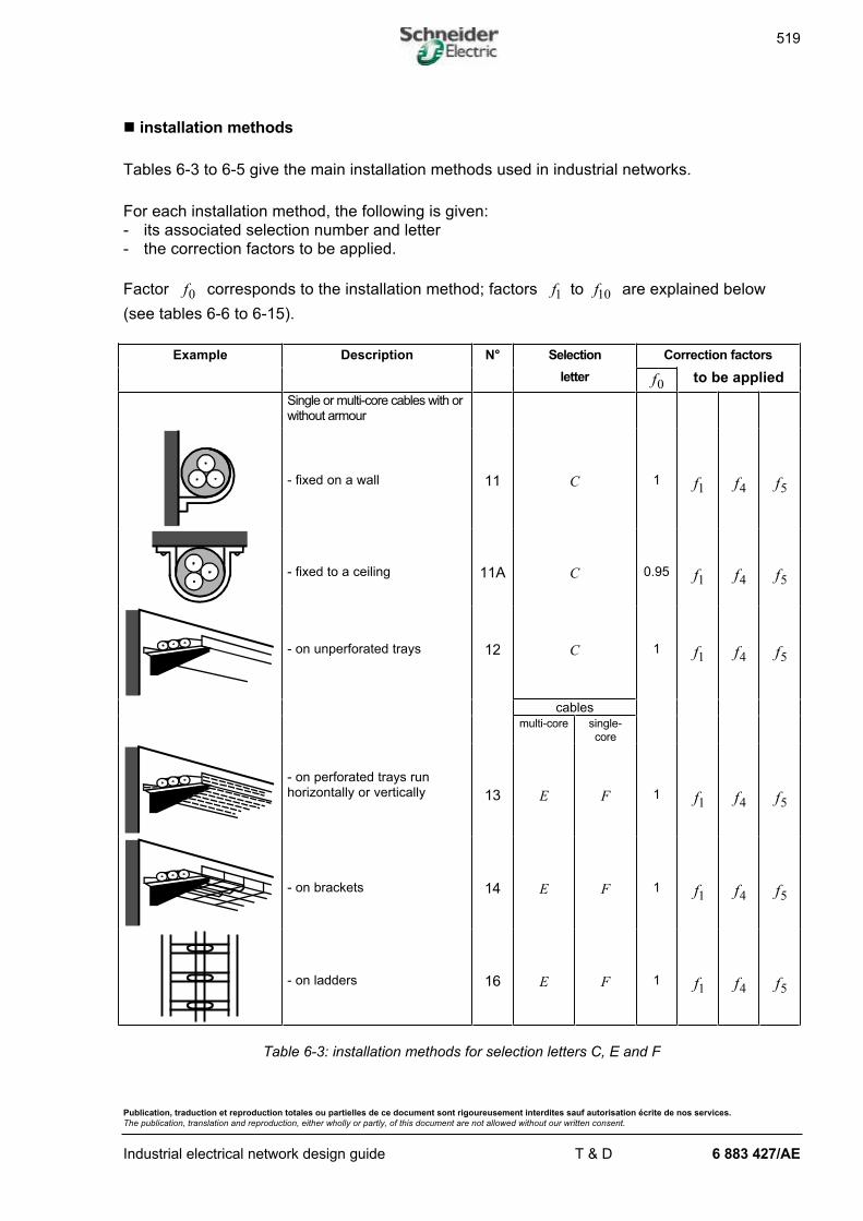
n installation methods
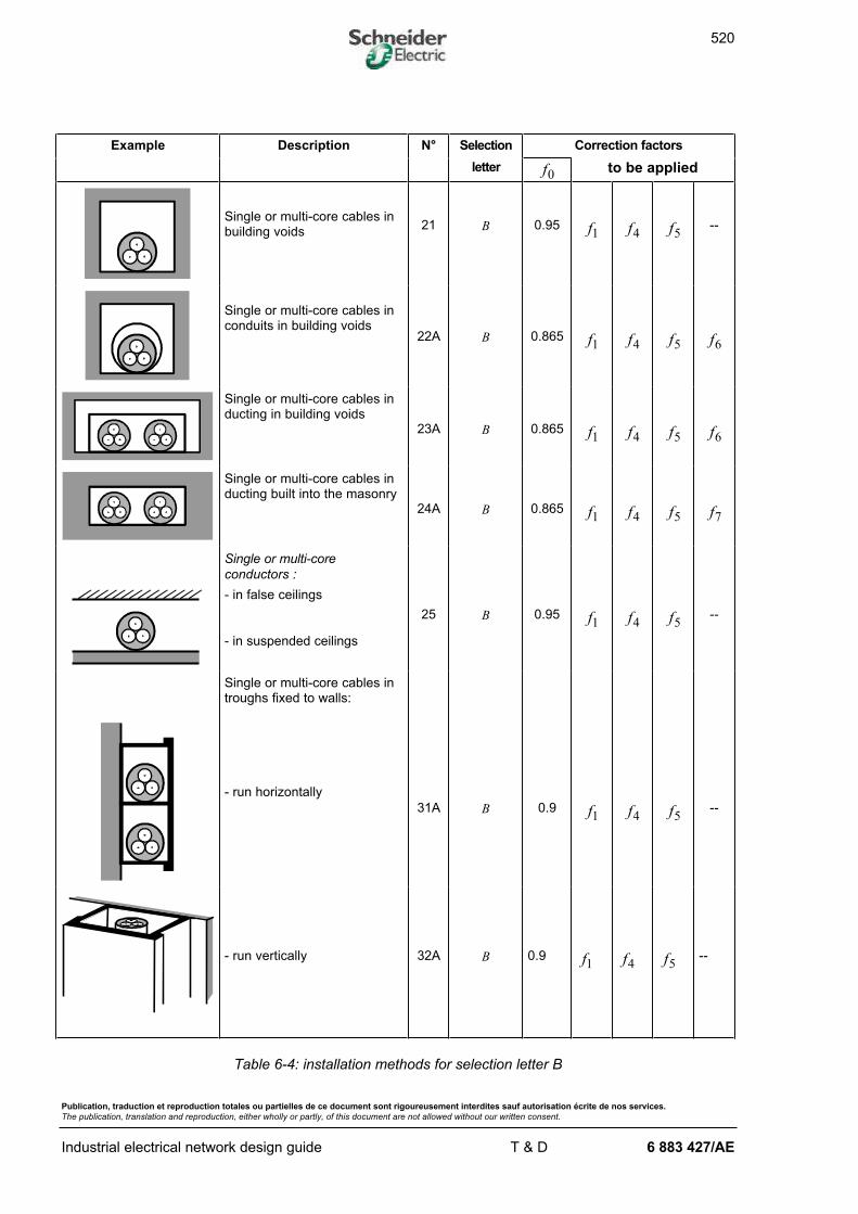
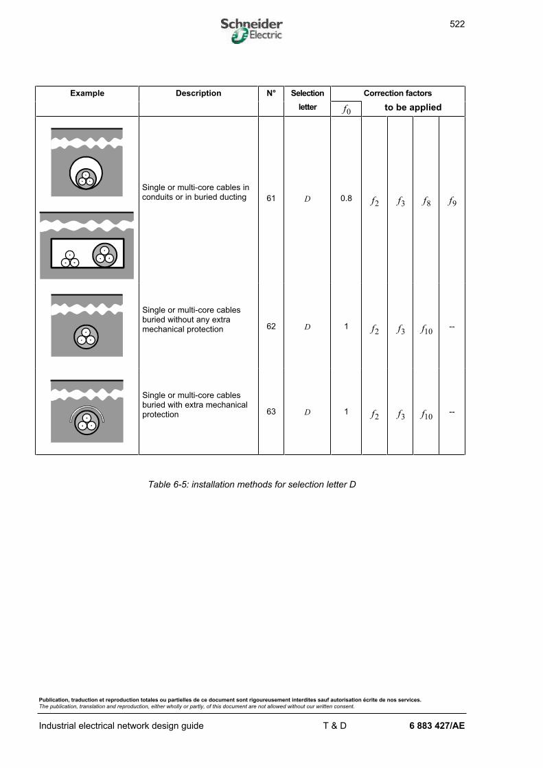
Tables 6-3 to 6-5 give the main installation methods used in industrial networks.
For each installation method, the following is given:
- its associated selection number and letter
- the correction factors to be applied.
Factor f0 corresponds to the installation method; factors f f1 10to are explained below
(see tables 6-6 to 6-15).
Example Description N° Selection Correction factors
letter f0 to be applied
Single or multi-core cables with orwithout armour
- fixed on a wall 11 C 1 f1 f4 f5
- fixed to a ceiling 11A C 0.95 f1 f4 f5
- on unperforated trays 12 C 1 f1 f4 f5
cablesmulti-core single-
core
- on perforated trays runhorizontally or vertically 13 E F 1 f1 f4 f5
- on brackets 14 E F 1 f1 f4 f5
- on ladders 16 E F 1 f1 f4 f5
Table 6-3: installation methods for selection letters C, E and F
520
Publication, traduction et reproduction totales ou partielles de ce document sont rigoureusement interdites sauf autorisation écrite de nos services.
The publication, translation and reproduction, either wholly or partly, of this document are not allowed without our written consent.
Industrial electrical network design guide T & D 6 883 427/AE
Example Description N° Selection Correction factors
letter f0 to be applied
Single or multi-core cables inbuilding voids
21 B 0.95 f1 f4 f5--
Single or multi-core cables inconduits in building voids
22A B 0.865 f1 f4 f5 f6
Single or multi-core cables inducting in building voids
23A B 0.865 f1 f4 f5 f6
Single or multi-core cables inducting built into the masonry
24A B 0.865 f1 f4 f5 f7
Single or multi-core
conductors :
- in false ceilings
- in suspended ceilings
25 B 0.95 f1 f4 f5--
Single or multi-core cables introughs fixed to walls:
- run horizontally
31A B 0.9 f1 f4 f5--
- run vertically 32A B 0.9 f1 f4 f5--
Table 6-4: installation methods for selection letter B
521
Publication, traduction et reproduction totales ou partielles de ce document sont rigoureusement interdites sauf autorisation écrite de nos services.
The publication, translation and reproduction, either wholly or partly, of this document are not allowed without our written consent.
Industrial electrical network design guide T & D 6 883 427/AE
Example Description N° Selection Correction factors
letter f0 to be applied
Single or multi-core cables introughs built into floors 33A B 0.9 f1 f4 f5
--
Single or multi-core cables insuspended troughs 34A B 0.9 f1 f4 f5
--
Multi-core cables in enclosedchannels run horizontally orvertically
41 B 0.95 f1 f4 f5--
Single or multi-core cables inopen or ventilated channels
43 B 1 f1 f4 f5--
Table 6-4 (cont.): installation methods for selection letter B
522
Publication, traduction et reproduction totales ou partielles de ce document sont rigoureusement interdites sauf autorisation écrite de nos services.
The publication, translation and reproduction, either wholly or partly, of this document are not allowed without our written consent.
Industrial electrical network design guide T & D 6 883 427/AE
Example Description N° Selection Correction factors
letter f0 to be applied
Single or multi-core cables inconduits or in buried ducting 61 D 0.8 f2 f3 f8 f9
Single or multi-core cablesburied without any extramechanical protection 62 D 1 f2 f3 f10
--
Single or multi-core cablesburied with extra mechanicalprotection 63 D 1 f2 f3 f10
--
Table 6-5: installation methods for selection letter D
523
Publication, traduction et reproduction totales ou partielles de ce document sont rigoureusement interdites sauf autorisation écrite de nos services.
The publication, translation and reproduction, either wholly or partly, of this document are not allowed without our written consent.
Industrial electrical network design guide T & D 6 883 427/AE
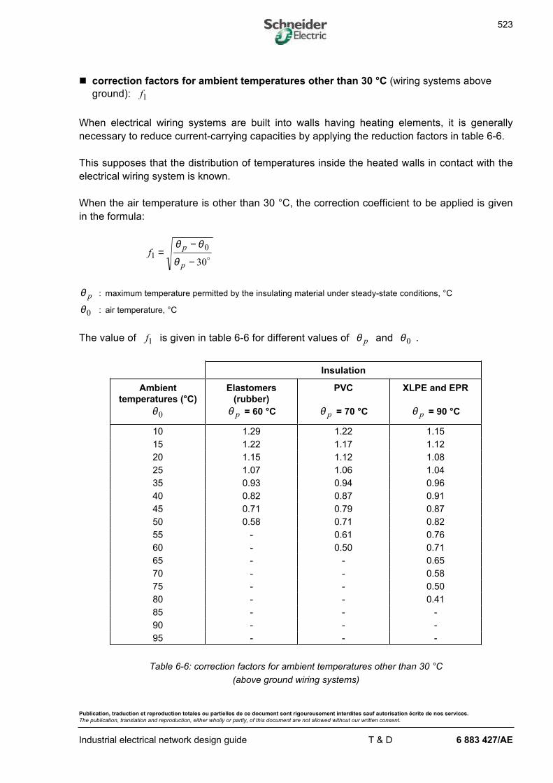
n correction factors for ambient temperatures other than 30 °C (wiring systems above
ground): f1
When electrical wiring systems are built into walls having heating elements, it is generally
necessary to reduce current-carrying capacities by applying the reduction factors in table 6-6.
This supposes that the distribution of temperatures inside the heated walls in contact with the
electrical wiring system is known.
When the air temperature is other than 30 °C, the correction coefficient to be applied is given
in the formula:
fp
p1
0
30=
−
−
θ θ
θ o
θ p : maximum temperature permitted by the insulating material under steady-state conditions, °C
θ 0 : air temperature, °C
The value of f1 is given in table 6-6 for different values of θ p and θ 0 .
Insulation
Ambient
temperatures (°C)
θ 0
Elastomers
(rubber)
θ p = 60 °C
PVC
θ p = 70 °C
XLPE and EPR
θ p = 90 °C
10 1.29 1.22 1.15
15 1.22 1.17 1.12
20 1.15 1.12 1.08
25 1.07 1.06 1.04
35 0.93 0.94 0.96
40 0.82 0.87 0.91
45 0.71 0.79 0.87
50 0.58 0.71 0.82
55 - 0.61 0.76
60 - 0.50 0.71
65 - - 0.65
70 - - 0.58
75 - - 0.50
80 - - 0.41
85 - - -
90 - - -
95 - - -
Table 6-6: correction factors for ambient temperatures other than 30 °C
(above ground wiring systems)
524
Publication, traduction et reproduction totales ou partielles de ce document sont rigoureusement interdites sauf autorisation écrite de nos services.
The publication, translation and reproduction, either wholly or partly, of this document are not allowed without our written consent.
Industrial electrical network design guide T & D 6 883 427/AE
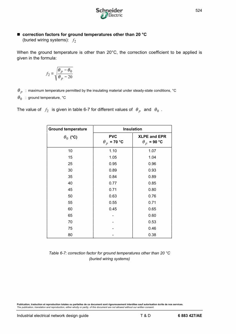
n correction factors for ground temperatures other than 20 °C
(buried wiring systems): f2
When the ground temperature is other than 20°C, the correction coefficient to be applied is
given in the formula:
fp
p2
0
20=
−−
θ θθ
θ p : maximum temperature permitted by the insulating material under steady-state conditions, °C
θ 0 : ground temperature, °C
The value of f2 is given in table 6-7 for different values of θ p and θ 0 .
Ground temperature Insulation
θ 0 (°C) PVC
θ p = 70 °C
XLPE and EPR
θ p = 90 °C
10 1.10 1.07
15 1.05 1.04
25 0.95 0.96
30 0.89 0.93
35 0.84 0.89
40 0.77 0.85
45 0.71 0.80
50 0.63 0.76
55 0.55 0.71
60 0.45 0.65
65 - 0.60
70 - 0.53
75 - 0.46
80 - 0.38
Table 6-7: correction factor for ground temperatures other than 20 °C
(buried wiring systems)
525
Publication, traduction et reproduction totales ou partielles de ce document sont rigoureusement interdites sauf autorisation écrite de nos services.
The publication, translation and reproduction, either wholly or partly, of this document are not allowed without our written consent.
Industrial electrical network design guide T & D 6 883 427/AE
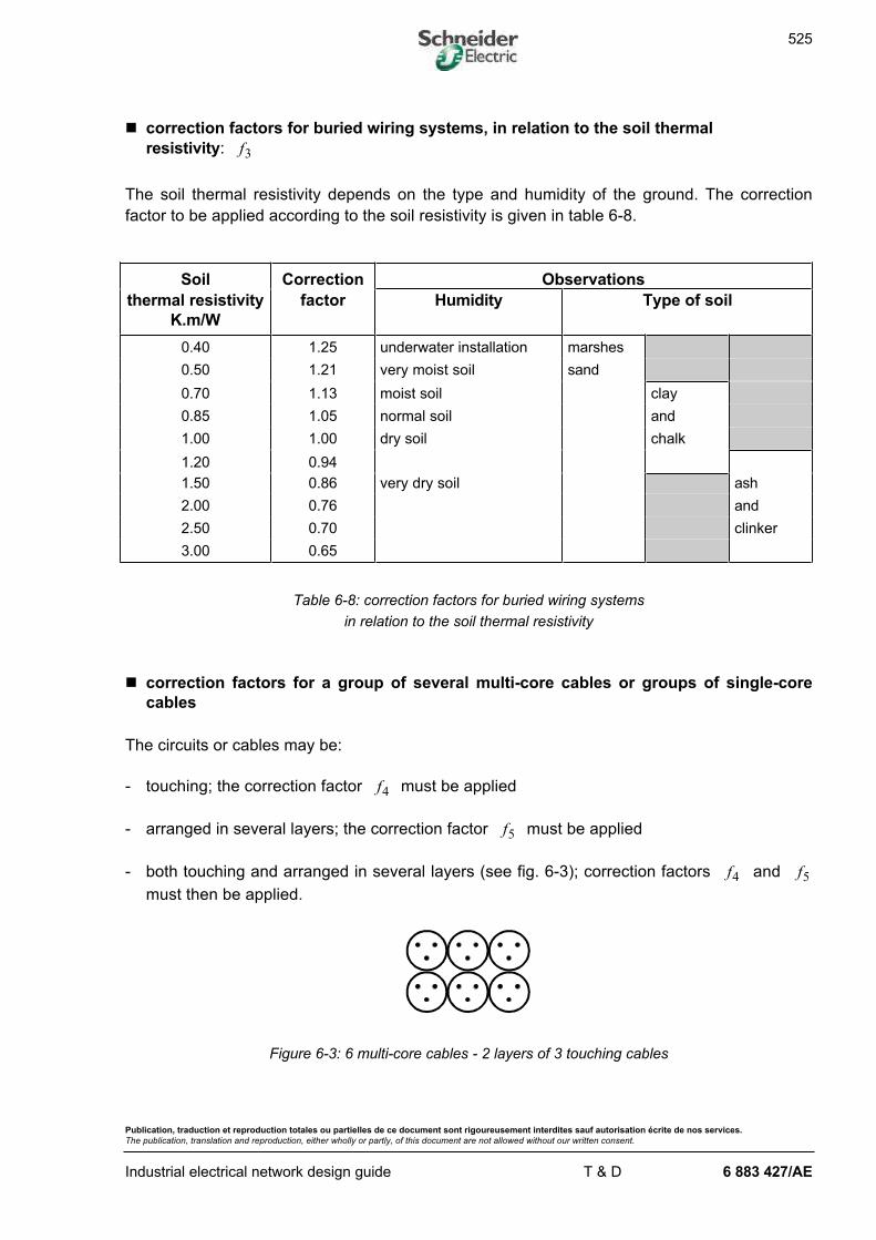
n correction factors for buried wiring systems, in relation to the soil thermal
resistivity: f3
The soil thermal resistivity depends on the type and humidity of the ground. The correction
factor to be applied according to the soil resistivity is given in table 6-8.
Soil Correction Observations
thermal resistivity
K.m/W
factor Humidity Type of soil
0.40 1.25 underwater installation marshes
0.50 1.21 very moist soil sand
0.70 1.13 moist soil clay
0.85 1.05 normal soil and
1.00 1.00 dry soil chalk
1.20 0.94
1.50 0.86 very dry soil ash
2.00 0.76 and
2.50 0.70 clinker
3.00 0.65
Table 6-8: correction factors for buried wiring systems
in relation to the soil thermal resistivity
n correction factors for a group of several multi-core cables or groups of single-core
cables
The circuits or cables may be:
- touching; the correction factor f4 must be applied
- arranged in several layers; the correction factor f5 must be applied
- both touching and arranged in several layers (see fig. 6-3); correction factors f4 and f5
must then be applied.
Figure 6-3: 6 multi-core cables - 2 layers of 3 touching cables
526
Publication, traduction et reproduction totales ou partielles de ce document sont rigoureusement interdites sauf autorisation écrite de nos services.
The publication, translation and reproduction, either wholly or partly, of this document are not allowed without our written consent.
Industrial electrical network design guide T & D 6 883 427/AE
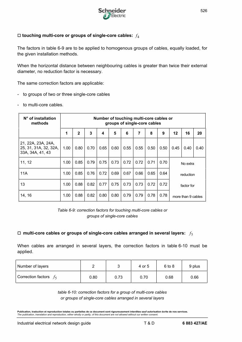
o touching multi-core or groups of single-core cables: f4
The factors in table 6-9 are to be applied to homogenous groups of cables, equally loaded, for
the given installation methods.
When the horizontal distance between neighbouring cables is greater than twice their external
diameter, no reduction factor is necessary.
The same correction factors are applicable:
- to groups of two or three single-core cables
- to multi-core cables.
N° of installation
methods
Number of touching multi-core cables or
groups of single-core cables
1 2 3 4 5 6 7 8 9 12 16 20
21, 22A, 23A, 24A,25, 31, 31A, 32, 32A,33A, 34A, 41, 43
1.00 0.80 0.70 0.65 0.60 0.55 0.55 0.50 0.50 0.45 0.40 0.40
11, 12 1.00 0.85 0.79 0.75 0.73 0.72 0.72 0.71 0.70 No extra
11A 1.00 0.85 0.76 0.72 0.69 0.67 0.66 0.65 0.64 reduction
13 1.00 0.88 0.82 0.77 0.75 0.73 0.73 0.72 0.72 factor for
14, 16 1.00 0.88 0.82 0.80 0.80 0.79 0.79 0.78 0.78 more than 9 cables
Table 6-9: correction factors for touching multi-core cables or
groups of single-core cables
o multi-core cables or groups of single-core cables arranged in several layers: f5
When cables are arranged in several layers, the correction factors in table 6-10 must be
applied.
Number of layers 2 3 4 or 5 6 to 8 9 plus
Correction factors f5 0.80 0.73 0.70 0.68 0.66
table 6-10: correction factors for a group of multi-core cables
or groups of single-core cables arranged in several layers
527
Publication, traduction et reproduction totales ou partielles de ce document sont rigoureusement interdites sauf autorisation écrite de nos services.
The publication, translation and reproduction, either wholly or partly, of this document are not allowed without our written consent.
Industrial electrical network design guide T & D 6 883 427/AE
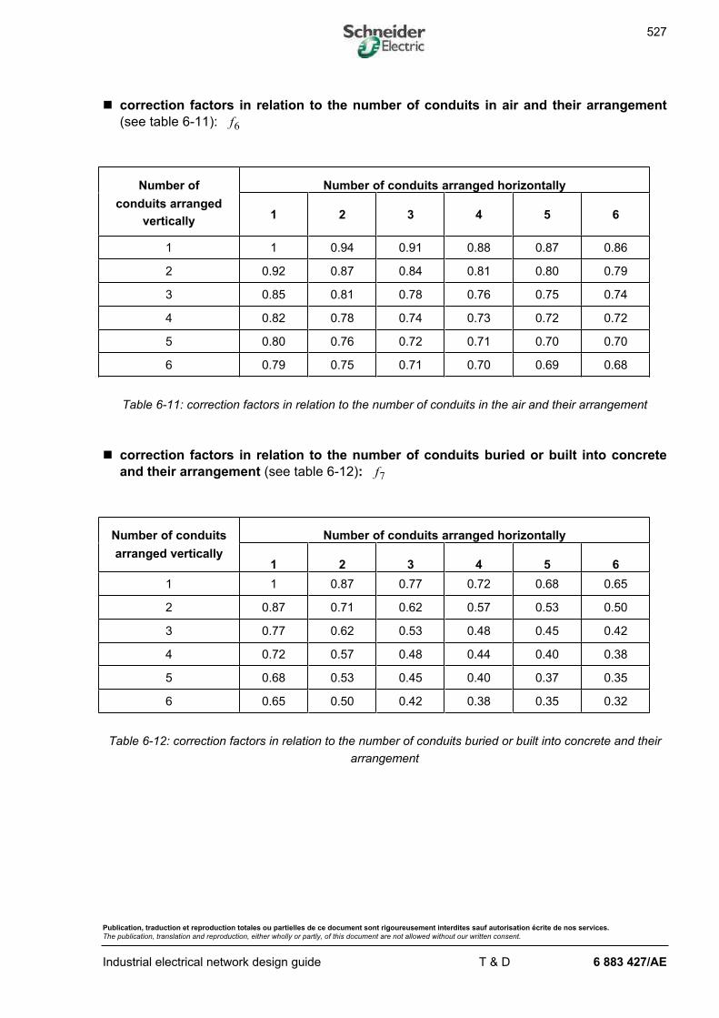
n correction factors in relation to the number of conduits in air and their arrangement
(see table 6-11): f6
Number of Number of conduits arranged horizontally
conduits arranged
vertically1 2 3 4 5 6
1 1 0.94 0.91 0.88 0.87 0.86
2 0.92 0.87 0.84 0.81 0.80 0.79
3 0.85 0.81 0.78 0.76 0.75 0.74
4 0.82 0.78 0.74 0.73 0.72 0.72
5 0.80 0.76 0.72 0.71 0.70 0.70
6 0.79 0.75 0.71 0.70 0.69 0.68
Table 6-11: correction factors in relation to the number of conduits in the air and their arrangement
n correction factors in relation to the number of conduits buried or built into concrete
and their arrangement (see table 6-12): f7
Number of conduits Number of conduits arranged horizontally
arranged vertically1 2 3 4 5 6
1 1 0.87 0.77 0.72 0.68 0.65
2 0.87 0.71 0.62 0.57 0.53 0.50
3 0.77 0.62 0.53 0.48 0.45 0.42
4 0.72 0.57 0.48 0.44 0.40 0.38
5 0.68 0.53 0.45 0.40 0.37 0.35
6 0.65 0.50 0.42 0.38 0.35 0.32
Table 6-12: correction factors in relation to the number of conduits buried or built into concrete and their
arrangement
528
Publication, traduction et reproduction totales ou partielles de ce document sont rigoureusement interdites sauf autorisation écrite de nos services.
The publication, translation and reproduction, either wholly or partly, of this document are not allowed without our written consent.
Industrial electrical network design guide T & D 6 883 427/AE
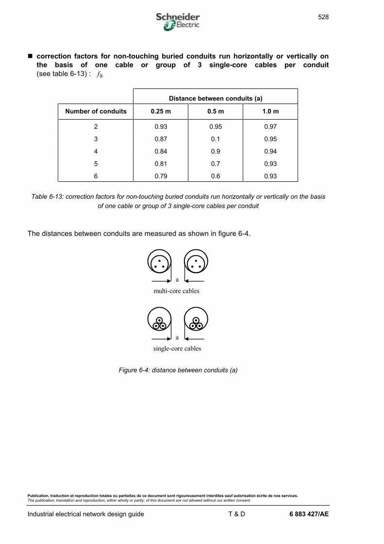
n correction factors for non-touching buried conduits run horizontally or vertically on
the basis of one cable or group of 3 single-core cables per conduit
(see table 6-13) : f8
Distance between conduits (a)
Number of conduits 0.25 m 0.5 m 1.0 m
2 0.93 0.95 0.97
3 0.87 0.1 0.95
4 0.84 0.9 0.94
5 0.81 0.7 0.93
6 0.79 0.6 0.93
Table 6-13: correction factors for non-touching buried conduits run horizontally or vertically on the basis
of one cable or group of 3 single-core cables per conduit
The distances between conduits are measured as shown in figure 6-4.
a
multi-core cables
a
single-core cables
Figure 6-4: distance between conduits (a)
529
Publication, traduction et reproduction totales ou partielles de ce document sont rigoureusement interdites sauf autorisation écrite de nos services.
The publication, translation and reproduction, either wholly or partly, of this document are not allowed without our written consent.
Industrial electrical network design guide T & D 6 883 427/AE
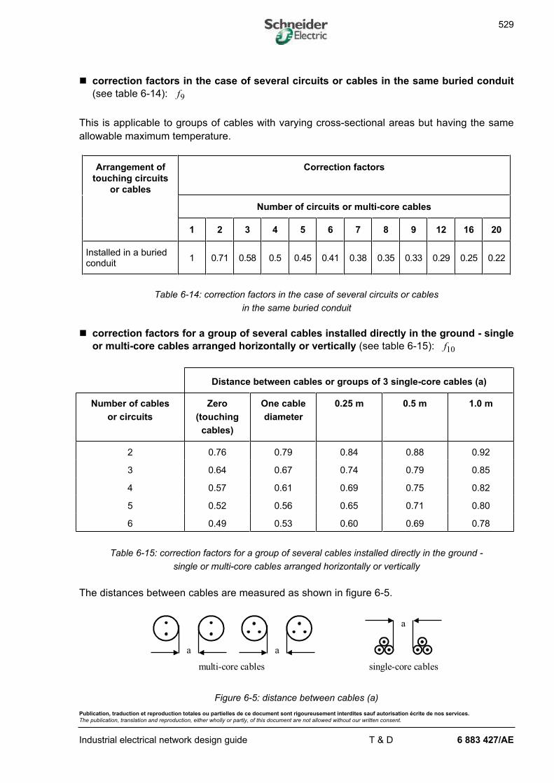
n correction factors in the case of several circuits or cables in the same buried conduit
(see table 6-14): f9
This is applicable to groups of cables with varying cross-sectional areas but having the same
allowable maximum temperature.
Arrangement of
touching circuits
or cables
Correction factors
Number of circuits or multi-core cables
1 2 3 4 5 6 7 8 9 12 16 20
Installed in a buriedconduit
1 0.71 0.58 0.5 0.45 0.41 0.38 0.35 0.33 0.29 0.25 0.22
Table 6-14: correction factors in the case of several circuits or cables
in the same buried conduit
n correction factors for a group of several cables installed directly in the ground - single
or multi-core cables arranged horizontally or vertically (see table 6-15): f10
Distance between cables or groups of 3 single-core cables (a)
Number of cables
or circuits
Zero
(touching
cables)
One cable
diameter
0.25 m 0.5 m 1.0 m
2 0.76 0.79 0.84 0.88 0.92
3 0.64 0.67 0.74 0.79 0.85
4 0.57 0.61 0.69 0.75 0.82
5 0.52 0.56 0.65 0.71 0.80
6 0.49 0.53 0.60 0.69 0.78
Table 6-15: correction factors for a group of several cables installed directly in the ground -
single or multi-core cables arranged horizontally or vertically
The distances between cables are measured as shown in figure 6-5.
a
single-core cablesmulti-core cables
aa
Figure 6-5: distance between cables (a)
530
Publication, traduction et reproduction totales ou partielles de ce document sont rigoureusement interdites sauf autorisation écrite de nos services.
The publication, translation and reproduction, either wholly or partly, of this document are not allowed without our written consent.
Industrial electrical network design guide T & D 6 883 427/AE
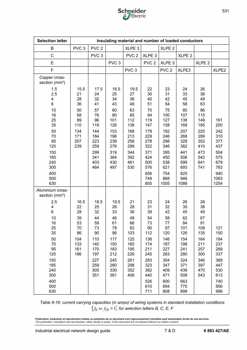
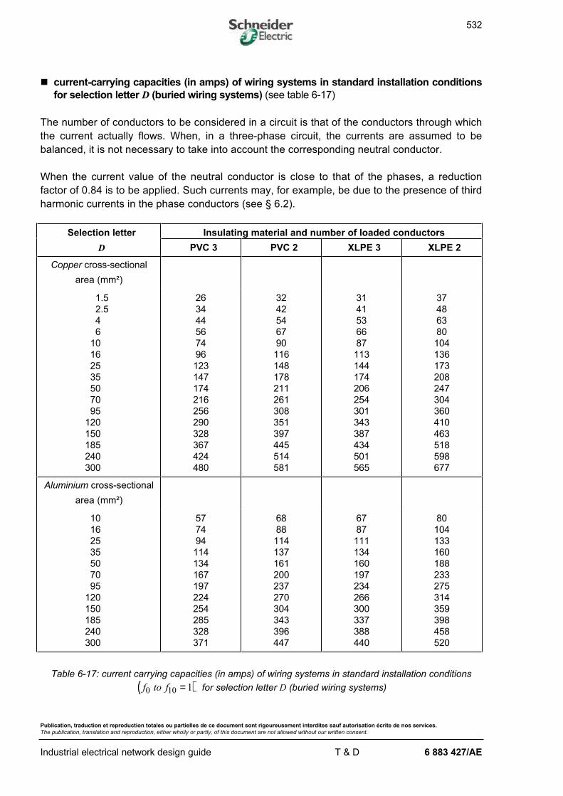
n current-carrying capacities (in amps) of wiring systems in standard installation
conditions for selection letters B, C, E, F
The current carrying capacities given in table 6-16 are valid for simple circuits made up of the
following number of conductors:
Selection letter B:
- two insulated conductors or two single-core cables or one two-core cable
- three insulated conductors or three single-core cables or one three-core cable
Selection letter C:
- two single-core cables or one two-core cable
- three single-core cables or one three-core cable
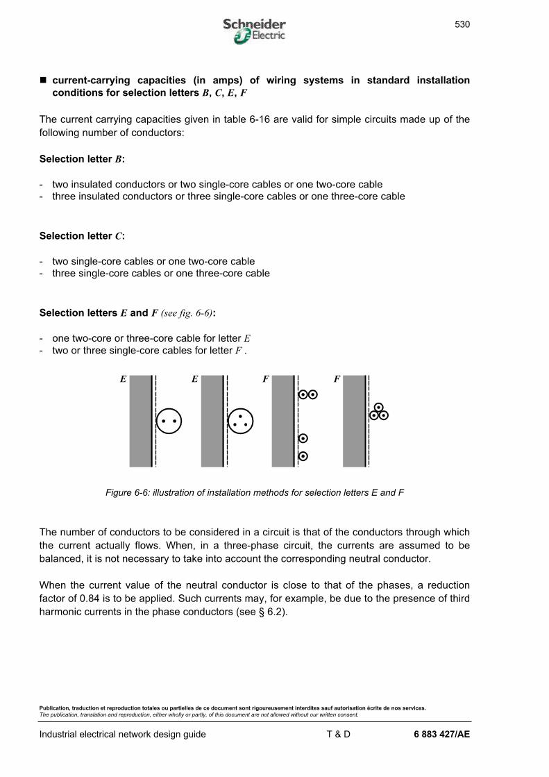
Selection letters E and F (see fig. 6-6):
- one two-core or three-core cable for letter E
- two or three single-core cables for letter F .
E E F F
Figure 6-6: illustration of installation methods for selection letters E and F
The number of conductors to be considered in a circuit is that of the conductors through which
the current actually flows. When, in a three-phase circuit, the currents are assumed to be
balanced, it is not necessary to take into account the corresponding neutral conductor.
When the current value of the neutral conductor is close to that of the phases, a reduction
factor of 0.84 is to be applied. Such currents may, for example, be due to the presence of third
harmonic currents in the phase conductors (see § 6.2).
531
Publication, traduction et reproduction totales ou partielles de ce document sont rigoureusement interdites sauf autorisation écrite de nos services.
The publication, translation and reproduction, either wholly or partly, of this document are not allowed without our written consent.
Industrial electrical network design guide T & D 6 883 427/AE
Selection letter Insulating material and number of loaded conductors
B PVC 3 PVC 2 XLPE 3 XLPE 2
C PVC 3 PVC 2 XLPE 3 XLPE 2
E PVC 3 PVC 2 XLPE 3 XLPE 2
F PVC 3 PVC 2 XLPE3 XLPE2
Copper cross-
section (mm²)
1.5
2.5
4
6
15.5
21
28
36
17.5
24
32
41
18.5
25
34
43
19.5
27
36
48
22
30
40
51
23
31
42
54
24
33
45
58
26
36
49
63
10
16
25
35
50
68
89
110
57
76
96
119
60
80
101
126
63
85
112
138
70
94
119
147
75
100
127
158
80
107
138
169
86
115
149
185
161
200
50
70
95
120
134
171
207
239
144
184
223
259
153
196
238
276
168
213
258
299
179
229
278
322
192
246
298
346
207
268
328
382
225
289
352
410
242
310
377
437
150
185
240
300
299
341
403
464
319
364
430
497
344
392
461
530
371
424
500
576
395
450
538
621
441
506
599
693
473
542
641
741
504
575
679
783
400
500
630
656
749
855
754
868
1005
825
946
1088
940
1083
1254
Aluminium cross-
section (mm²)
2.5
4
6
16.5
22
28
18.5
25
32
19.5
26
33
21
28
36
23
31
39
24
32
42
26
35
45
28
38
49
10
16
25
35
39
53
70
86
44
59
73
90
46
61
78
96
49
66
83
103
54
73
90
112
58
77
97
120
62
84
101
126
67
91
108
135
121
150
50
70
95
120
104
133
161
186
110
140
170
197
117
150
183
212
125
160
195
226
136
174
211
245
146
187
227
263
154
198
241
280
164
211
257
300
184
237
289
337
150
185
240
300
227
259
305
351
245
280
330
381
261
298
352
406
283
323
382
440
304
347
409
471
324
371
439
508
346
397
470
543
389
447
530
613
400
500
630
526
610
711
600
694
808
663
770
899
740
856
996
Table 6-16: current carrying capacities (in amps) of wiring systems in standard installation conditions
( )f to f0 10 1= for selection letters B, C, E, F
532
Publication, traduction et reproduction totales ou partielles de ce document sont rigoureusement interdites sauf autorisation écrite de nos services.
The publication, translation and reproduction, either wholly or partly, of this document are not allowed without our written consent.
Industrial electrical network design guide T & D 6 883 427/AE
n current-carrying capacities (in amps) of wiring systems in standard installation conditions
for selection letter D (buried wiring systems) (see table 6-17)
The number of conductors to be considered in a circuit is that of the conductors through which
the current actually flows. When, in a three-phase circuit, the currents are assumed to be
balanced, it is not necessary to take into account the corresponding neutral conductor.
When the current value of the neutral conductor is close to that of the phases, a reduction
factor of 0.84 is to be applied. Such currents may, for example, be due to the presence of third
harmonic currents in the phase conductors (see § 6.2).
Selection letter Insulating material and number of loaded conductors
D PVC 3 PVC 2 XLPE 3 XLPE 2
Copper cross-sectional
area (mm²)
1.5
2.5
4
6
10
16
25
35
50
70
95
120
150
185
240
300
26
34
44
56
74
96
123
147
174
216
256
290
328
367
424
480
32
42
54
67
90
116
148
178
211
261
308
351
397
445
514
581
31
41
53
66
87
113
144
174
206
254
301
343
387
434
501
565
37
48
63
80
104
136
173
208
247
304
360
410
463
518
598
677
Aluminium cross-sectional
area (mm²)
10
16
25
35
50
70
95
120
150
185
240
300
57
74
94
114
134
167
197
224
254
285
328
371
68
88
114
137
161
200
237
270
304
343
396
447
67
87
111
134
160
197
234
266
300
337
388
440
80
104
133
160
188
233
275
314
359
398
458
520
Table 6-17: current carrying capacities (in amps) of wiring systems in standard installation conditions
( )f to f0 10 1= for selection letter D (buried wiring systems)

533
Publication, traduction et reproduction totales ou partielles de ce document sont rigoureusement interdites sauf autorisation écrite de nos services.
The publication, translation and reproduction, either wholly or partly, of this document are not allowed without our written consent.
Industrial electrical network design guide T & D 6 883 427/AE
6.1.5. Practical method for determining the minimum cross-sectional area of an LV
wiring system
determination of the protective device rated current or
setting current taken to be just higher than the designcurrent:
determination of the cross-sectional area of the wiring systemconductors able to carry or :
- calculate the equivalent current (1)
- determine the cross-sectional area able to carry in standard
installation conditions, depending on the insulating material, the
number of loaded conductors and the type of conductor (copper or
aluminium) (see tab. 8-16 and 8-17)
check of other required conditions:
- maximum voltage drop
- maximum length for protection against indirect contact
(IT and TN earthing systems)
- check of thermal withstand in case of short circuit
conductor
installation
conditions
determination of theselection letter and
overall correction
factor
(see tab. 8-3 to 8-5)
design current
determination of current of the wiring system to be
protected by the protective device
fuse circuit-breaker
f
IB
In
Iz1 Iz2
I Iz nand
In
Iz
SIz1 Iz2
Iz'
In I Iset B
I I if I A
I I if I A
z n n
z n n
1 31 10
1 21 10
.
.
I An 25or
S
(1) is an equivalent current which, in standard installationconditions, causes the same thermal effect as or
in actual installation conditions
Iz'
Iz1 Iz2
or
Isetor
Iset
I I if I Az n n110 25.
II
f
I
fz
z z' 1 2or
Iset
Figure 6-7: logigram for determining the cross-sectional area of a LV wiring system
534
Publication, traduction et reproduction totales ou partielles de ce document sont rigoureusement interdites sauf autorisation écrite de nos services.
The publication, translation and reproduction, either wholly or partly, of this document are not allowed without our written consent.
Industrial electrical network design guide T & D 6 883 427/AE
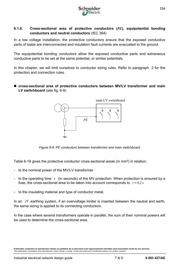
6.1.6. Cross-sectional area of protective conductors (PE), equipotential bonding
conductors and neutral conductors (IEC 364)
In a low voltage installation, the protective conductors ensure that the exposed conductive
parts of loads are interconnected and insulation fault currents are evacuated to the ground.
The equipotential bonding conductors allow the exposed conductive parts and extraneous
conductive parts to be set at the same potential, or similar potentials.
In this chapter, we will limit ourselves to conductor sizing rules. Refer to paragraph 2 for the
protection and connection rules.
n cross-sectional area of protective conductors between MV/LV transformer and main
LV switchboard (see fig. 6-8)
PE
main LV switchboard
Figure 6-8: PE conductors between transformer and main switchboard
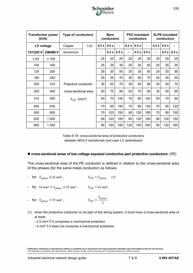
Table 6-18 gives the protective conductor cross-sectional areas (in mm²) in relation:
- to the nominal power of the MV/LV transformer
- to the operating time t (in seconds) of the MV protection. When protection is ensured by a
fuse, the cross-sectional area to be taken into account corresponds to t s= 0 2.
- to the insulating material and type of conductor metal.
In an IT earthing system, if an overvoltage limiter is inserted between the neutral and earth,
the same sizing is applied to its connecting conductors.
In the case where several transformers operate in parallel, the sum of their nominal powers will
be used to determine the cross-sectional area.
535
Publication, traduction et reproduction totales ou partielles de ce document sont rigoureusement interdites sauf autorisation écrite de nos services.
The publication, translation and reproduction, either wholly or partly, of this document are not allowed without our written consent.
Industrial electrical network design guide T & D 6 883 427/AE
Transformer power
(kVA)
Type of conductors Bare
conductors
PVC-insulated
conductors
XLPE-insulated
conductors
LV voltage Copper t (s) 0.2 s 0.5 s - 0.2 s 0.5 s - 0.2 s 0.5 s -
127/220 V 230/400 V Aluminium - 0.2 s 0.5 s - 0.2 s 0.5 s - 0.2 s 0.5 s
≤ 63 ≤ 100 25 25 25 25 25 25 25 25 25
100 160 25 25 35 25 25 50 25 25 35
125 200 25 35 50 25 35 50 25 25 50
160 250 25 35 70 35 50 70 25 35 50
200 315 Potective conductor 35 50 70 35 50 95 35 50 70
250 400 cross-sectional area 50 70 95 50 70 95 35 50 95
315 500 SPE (mm²) 50 70 120 70 95 120 50 70 95
400 630 70 95 150 70 95 150 70 95 120
500 800 70 120 150 95 120 185 70 95 150
630 1 000 95 120 185 95 120 185 95 120 150
800 1 250 95 150 185 120 150 240 95 120 185
Table 6-18: cross-sectional area of protective conductors
between MV/LV transformer and main LV switchboard
n cross-sectional areas of low voltage exposed conductive part protective conductors: (PE)
The cross-sectional area of the PE conductor is defined in relation to the cross-sectional area
of the phases (for the same metal conductor) as follows:
- for S mmphase ≤16 ² , S SPE phase= (1)
- for 16 35mm S mmphase² ²< ≤ , S mmPE =16 ²
- for S mmphase > 35 ² , SS
PEphase=2
(1) when the protective conductor is not part of the wiring system, it must have a cross-sectional area of
at least:
- 2.5 mm² if it comprises a mechanical protection
- 4 mm² if it does not comprise a mechanical protection
536
Publication, traduction et reproduction totales ou partielles de ce document sont rigoureusement interdites sauf autorisation écrite de nos services.
The publication, translation and reproduction, either wholly or partly, of this document are not allowed without our written consent.
Industrial electrical network design guide T & D 6 883 427/AE
In the TT earthing system, the protective conductor cross-sectional area may be limited to:
- 25 mm² for copper
- 35 mm² for aluminium
on condition that the neutral and exposed conductive part earth electrodes are separate,
otherwise the conditions of the TN earthing system are applicable (in a TT earthing
system, there may be an involuntary connection via the metal structure or other part between
the two earth electrodes; the earth fault current is then high).
n cross-sectional area of equipotential bonding conductors
o main equipotential bonding conductor
Its cross-sectional area must be at least equal to half the cross-sectional area of the
installation's largest protective conductor, with a minimum of 6 mm². However, it may be limited
to 25 mm² for copper or 35 mm² for aluminium.
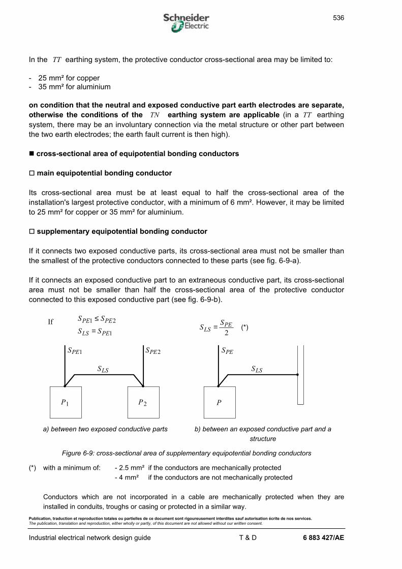
o supplementary equipotential bonding conductor
If it connects two exposed conductive parts, its cross-sectional area must not be smaller than
the smallest of the protective conductors connected to these parts (see fig. 6-9-a).
If it connects an exposed conductive part to an extraneous conductive part, its cross-sectional
area must not be smaller than half the cross-sectional area of the protective conductor
connected to this exposed conductive part (see fig. 6-9-b).
IfS SPE PE1 2≤
S SLS PE= 1S
SLS
PE=2
(*)
SPE1 SPE2
SLS
P1 P2
SLS
SPE
P
a) between two exposed conductive parts b) between an exposed conductive part and a
structure
Figure 6-9: cross-sectional area of supplementary equipotential bonding conductors
(*) with a minimum of: - 2.5 mm² if the conductors are mechanically protected
- 4 mm² if the conductors are not mechanically protected
Conductors which are not incorporated in a cable are mechanically protected when they are
installed in conduits, troughs or casing or protected in a similar way.
537
Publication, traduction et reproduction totales ou partielles de ce document sont rigoureusement interdites sauf autorisation écrite de nos services.
The publication, translation and reproduction, either wholly or partly, of this document are not allowed without our written consent.
Industrial electrical network design guide T & D 6 883 427/AE
n cross-sectional area of PEN conductors
In the case of a TNC earthing system, the protective conductor also plays the role of the
neutral conductor.
In this case, the cross-sectional area of the PEN must be at least equal to the greatest value
resulting from the following requirements:
- SPEN ≥−
−
10
16
2
2
mm
mm
for copper
for aluminium
- meet the conditions relating to the PE conductor
- meet the conditions required for the neutral conductor cross-sectional area.
n cross-sectional area of the neutral conductor
- The neutral conductor must have the same cross-sectional area as the phase conductors in
the following cases:
. single-phase circuit
. three-phase circuit having phase cross-sectional areas smaller than or equal to 16 mm²
for copper or 25 mm² for aluminium.
- For three-phase circuits having a phase cross-sectional area greater than 16 mm² for
copper or 25 mm² for aluminium, the neutral cross-sectional area may be smaller than that
of the phases as long as the following conditions are met:
. the maximum current likely to continuously circulate in the neutral is lower than the
current-carrying capacity of the chosen cross-sectional area. The unbalance of single-
phase loads and third and multiples of third harmonics which may require the use of a
cross-sectional area greater than the phases must be taken into account (see § 8.2 -
neutral conductor heating).
. the neutral conductor is protected against overcurrent by a fuse or a circuit-breaker trip
setting suitable to its cross-sectional area.
. the cross-sectional area of the neutral conductor is at least equal to 16 mm² for copper or
25 mm² for aluminium.

538
Publication, traduction et reproduction totales ou partielles de ce document sont rigoureusement interdites sauf autorisation écrite de nos services.
The publication, translation and reproduction, either wholly or partly, of this document are not allowed without our written consent.
Industrial electrical network design guide T & D 6 883 427/A
6.1.7. Checking voltage drops
The voltage drop over a wiring system is calculated using the following formula:
∆V bL
SL IB= +
×ρ ϕ λ ϕ1 cos sin
∆V : voltage drop, in volts
b : coefficient
=
=
1
2
for three - phase circuit
for single - phase circuit
ρ1 : conductor resistivity during normal service, i.e. 1.25 times that at 20 °C
ρ1 = 0.0225 Ω mm²/m for copper; ρ1 = 0.036 Ω mm²/m for aluminium
L : length of wiring system, in metres
S : cross-sectional area of conductors, in mm²
cosϕ : power factor, in the absence of specific indications we can take cosϕ = 0.8 ( sinϕ = 0.6)
IB : maximum design current, in amps
λ : reactance per unit length of the conductors, in Ω/m
The values of λ in LV are:
- 0 08 10 3. /× − Ω m for three-core cables
- 0 09 10 3. /× − Ω m for single-core cables in a flat formation or triangular formation
- 0 15 10 3. /× − Ω m for single-core cables spaced by d r= 8
d : mean distance between conductor
r : radius of conductor cores
The relative voltage drop is defined as:
∆V
Vn
for phase-to-neutral fed three-phase or single-phase circuits
∆V
Un
for phase-to-phase fed single-phase circuits (in this case,
∆V represents a phase-to-phase voltage drop)
Vn : nominal single-phase voltage
Un : nominal phase-to-phase voltage
539
Publication, traduction et reproduction totales ou partielles de ce document sont rigoureusement interdites sauf autorisation écrite de nos services.
The publication, translation and reproduction, either wholly or partly, of this document are not allowed without our written consent.
Industrial electrical network design guide T & D 6 883 427/A
In accordance with IEC 364-5-52, in the absence of other considerations, it is recommended
that in practice the voltage between the origin of consumer's installation and the equipment
should not be greater than 4% of the nominal voltage of the installation.
n circuits feeding motors
The voltage drop is calculated by replacing the design current IB by the motor starting current.
Taking into account all the motors able to start simultaneously, the voltage drop must be lower
than 10% to ensure correct motor starting and not disturb the rest of the installation too much.
540
Publication, traduction et reproduction totales ou partielles de ce document sont rigoureusement interdites sauf autorisation écrite de nos services.
The publication, translation and reproduction, either wholly or partly, of this document are not allowed without our written consent.
Industrial electrical network design guide T & D 6 883 427/A
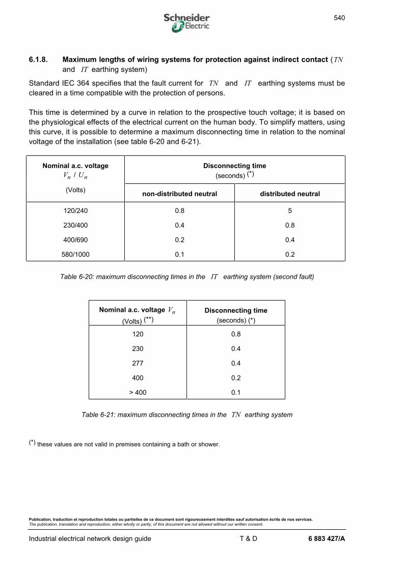
6.1.8. Maximum lengths of wiring systems for protection against indirect contact (TN
and IT earthing system)
Standard IEC 364 specifies that the fault current for TN and IT earthing systems must be
cleared in a time compatible with the protection of persons.
This time is determined by a curve in relation to the prospective touch voltage; it is based on
the physiological effects of the electrical current on the human body. To simplify matters, using
this curve, it is possible to determine a maximum disconnecting time in relation to the nominal
voltage of the installation (see table 6-20 and 6-21).
Nominal a.c. voltage
Vn / Un
Disconnecting time
(seconds) (*)
(Volts)non-distributed neutral distributed neutral
120/240
230/400
400/690
580/1000
0.8
0.4
0.2
0.1
5
0.8
0.4
0.2
Table 6-20: maximum disconnecting times in the IT earthing system (second fault)
Nominal a.c. voltage Vn
(Volts) (**)
Disconnecting time
(seconds) (*)
120
230
277
400
> 400
0.8
0.4
0.4
0.2
0.1
Table 6-21: maximum disconnecting times in the TN earthing system
(*) these values are not valid in premises containing a bath or shower.
541
Publication, traduction et reproduction totales ou partielles de ce document sont rigoureusement interdites sauf autorisation écrite de nos services.
The publication, translation and reproduction, either wholly or partly, of this document are not allowed without our written consent.
Industrial electrical network design guide T & D 6 883 427/A
Note 1: if the disconnecting time is more than the time t0 , but less than 5 seconds, protection is
allowed by IEC 364 (§ 413.1.3.5) in the following cases:
- in distribution circuits when the protective conductor at the downstream end of the circuit isdirectly connected to the main equipotential bonding.
- in terminal circuits supplying stationary equipment only and having a protective conductorthat is connected to the main equipotential bonding and which is located in the area that isinfluenced by the main equipotential bonding.
Note 2 : in the TT earthing system, protection is in general ensured by residual current devices whichare set to meet the following condition (see IEC 364, § 413.1.4.2):
R I VA A ≤ 50
RA : resistance of the earth electrode of the exposed conductive parts
IA : rated residual current of the circuit-breaker
If selectivity is seen to be necessary, an operating time at the most equal to 1 second isallowed in the distribution circuits without taking into account the touch voltage
Note 3 : in an IT earthing system, when the exposed conductive parts are earthed individually or in
groups, the conditions of the TT earthing system given in Note 2 must be met (see IEC 364,§ 413.1.5.3).
n circuit-breaker protection
IEC 364 specifies that the magnetic tripping threshold of the circuit-breaker in TN and IT
earthing systems must be lower than the minimum short-circuit current. Furthermore, any
eventual circuit-breaker time delay must be shorter than the maximum disconnecting time
defined in tables 6-20 and 6-21.
For a given circuit-breaker and cross-sectional area, there is thus a maximum circuit length not
to be exceeded in order to comply with the requirements concerning the protection of persons
against indirect contact.
In the following part of the chapter, we will apply the conventional method for determining
maximum circuit lengths. This is more restrictive than the impedance method, but can be
applied by carrying out the calculations by hand.
In the conventional method, we neglect the influence of the reactance of the conductors for
cross-sectional areas smaller than 150 mm².
For large cross-sectional areas, we will take into account the influence of the reactance by dividing
Lmax by:
- 1.15 for a cross-sectional area of 150 mm²
- 1.20 for a cross-sectional area of 185 mm²
- 1.25 for a cross-sectional area of 240 mm²
- 1.30 for a cross-sectional area of 300 mm².
542
Publication, traduction et reproduction totales ou partielles de ce document sont rigoureusement interdites sauf autorisation écrite de nos services.
The publication, translation and reproduction, either wholly or partly, of this document are not allowed without our written consent.
Industrial electrical network design guide T & D 6 883 427/A
Note: for minimum short-circuit current calculations, refer to the "Industrial network protection guide"§ 4.4.1.
o TN earthing system
The maximum length of a circuit in a TN earthing system is:
( )LV S
m I
n ph
mmax
.=
× ×× + ×0 8
1ρ
Lmax : maximum length in m
Vn : single-phase voltage in volts
S ph : cross-sectional area of the phases in mm²
ρ : resistivity of the conductors taken to be equal to 1.5 times that at 20 °C ( ρ = 0 027 2. /Ω mm m for
copper; ρ = 0 043 2. /Ω mm m for aluminium)
m =Sph
SPE
:
:
cross - sectional area of phases
cross - sectional area of protective conductor
Im : circuit-breaker magnetic trip operating current
o IT earthing system
The maximum length of a circuit in an IT earthing system is:
- if the neutral conductor is not distributed:
( )LV S
m I
n ph
mmax
.=
× × ×× + ×
0 8 3
2 1ρ
- if the neutral conductor is distributed:
( )LV S
m I
n
mmax
.=
× ×× + ×0 8
2 1
1
ρ
S1 :=
=
Sph
Sneutral
if the outgoing feeder considered does not have a neutral
if the outgoing feeder considered has a neutral
o TT earthing system
No condition on the wiring system length is specified since the protection of persons is
ensured by the residual current device.
543
Publication, traduction et reproduction totales ou partielles de ce document sont rigoureusement interdites sauf autorisation écrite de nos services.
The publication, translation and reproduction, either wholly or partly, of this document are not allowed without our written consent.
Industrial electrical network design guide T & D 6 883 427/A
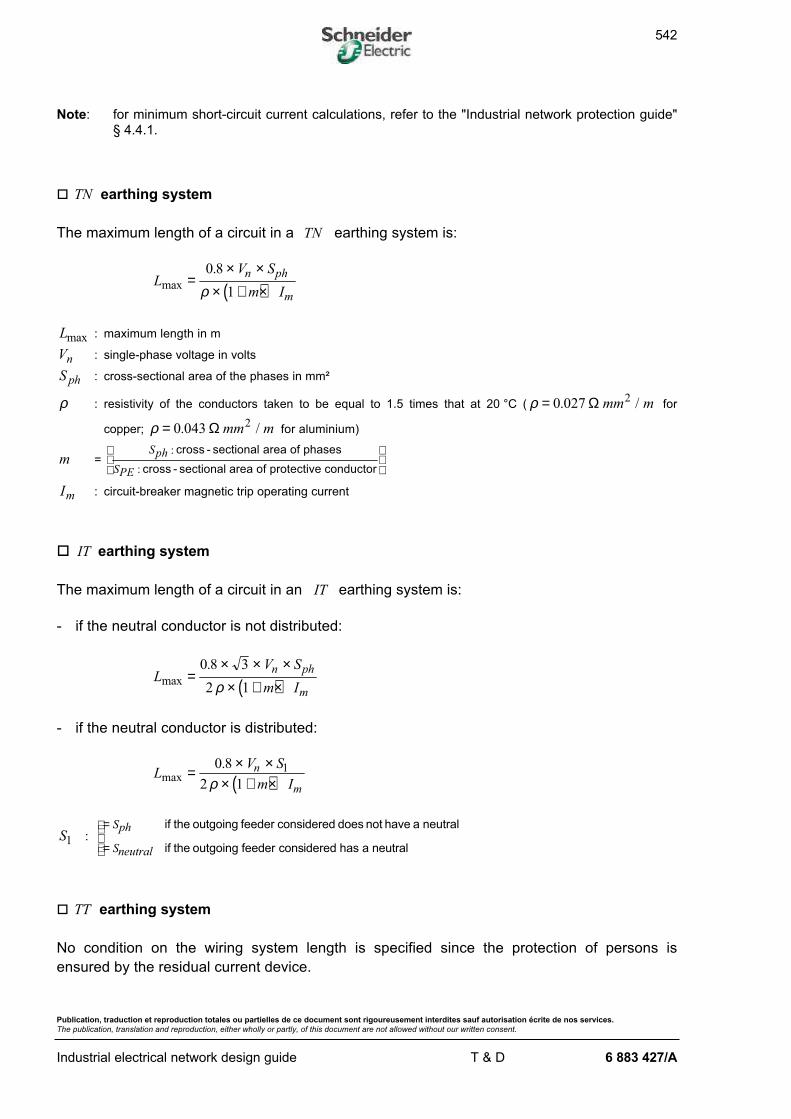
n fuse protection
Using the fuse fusing curve, we can determine the current Ia ensuring fusion of the fuse in
the time t0 specified in tables 6-20 and 6-21 (see fig. 6-10). We can then calculate the
maximum length of the wiring system in the same way as for the circuit-breaker replacing Im
by Ia .
t
t0
IaI
Figure 6-10: fuse fusing curve
n application
In practice, checking the cross-sectional area of the wiring system in relation to the protection
of persons against indirect contact consists in making sure that the length of the wiring system
is less than Lmax for a given arrangement.
If the wiring system length is greater than Lmax , we can take the following measures:
- choose a circuit-breaker (or trip relay) with a lower magnetic threshold if the selectivity
requirements permit this
- install a residual current circuit-breaker for TNS and IT earthing system (in a TNC
earthing system it is not possible to use a RCD)
- take larger phase and protective conductor cross-sectional areas meeting the maximum
length condition.
544
Publication, traduction et reproduction totales ou partielles de ce document sont rigoureusement interdites sauf autorisation écrite de nos services.
The publication, translation and reproduction, either wholly or partly, of this document are not allowed without our written consent.
Industrial electrical network design guide T & D 6 883 427/A
6.1.9. Checking the thermal withstand of conductors
When a short-circuit current flows through the conductors of a wiring system for a very short
time (up to five seconds), the heating of the conductors is considered to be adiabatic; this
means that the energy stored remains in the metal of the core and is not transmitted to the
insulating material. It is therefore necessary to check that the short-circuit thermal stress is
lower than the conductor thermal withstand:
t I k Sdis sc2 2 2≤
tdis : protective device disconnecting time in seconds
S : cross-sectional area of conductors in mm²
Isc : short-circuit current in A
The value of k depends on the core metal and the type of insulating material
(see table 6-22).
Insulating material
Core
PVC XLPE
Copper 115 135
Aluminium 74 87
Table 6-22: value of factor k in accordance with IEC 364-4-43
If the disconnecting time is given, the cross-sectional area must comply with:
SI
ktscdis≥ ×
545
Publication, traduction et reproduction totales ou partielles de ce document sont rigoureusement interdites sauf autorisation écrite de nos services.
The publication, translation and reproduction, either wholly or partly, of this document are not allowed without our written consent.
Industrial electrical network design guide T & D 6 883 427/A
n circuit-breaker protection
The check must be carried out for the maximum short-circuit current at the circuit-breaker
location.
The curves in manufacturers' catalogues give the maximum disconnecting time of the circuit-
breaker. When circuit-breaker tripping is time delayed, the disconnecting time is taken to be
equal to the time delay.
To check the thermal withstand, the short-circuit current value must be calculated with a
resistivity ρ of the conductors taken to be equal to 1.5 times that at 20 °C :
- ρ = 0 027 2. /Ω mm m for copper
- ρ = 0 043 2. /Ω mm m for aluminium
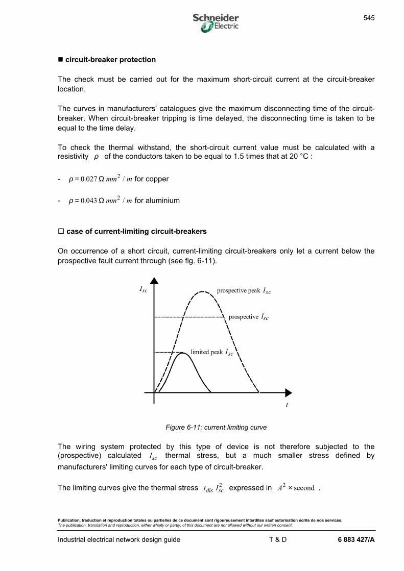
o case of current-limiting circuit-breakers
On occurrence of a short circuit, current-limiting circuit-breakers only let a current below the
prospective fault current through (see fig. 6-11).
t
prospective
limited peak Isc
Isc prospective peak Isc
Isc
Figure 6-11: current limiting curve
The wiring system protected by this type of device is not therefore subjected to the
(prospective) calculated Isc thermal stress, but a much smaller stress defined by
manufacturers' limiting curves for each type of circuit-breaker.
The limiting curves give the thermal stress t Idis sc2 expressed in A2 × second .
546
Publication, traduction et reproduction totales ou partielles de ce document sont rigoureusement interdites sauf autorisation écrite de nos services.
The publication, translation and reproduction, either wholly or partly, of this document are not allowed without our written consent.
Industrial electrical network design guide T & D 6 883 427/A
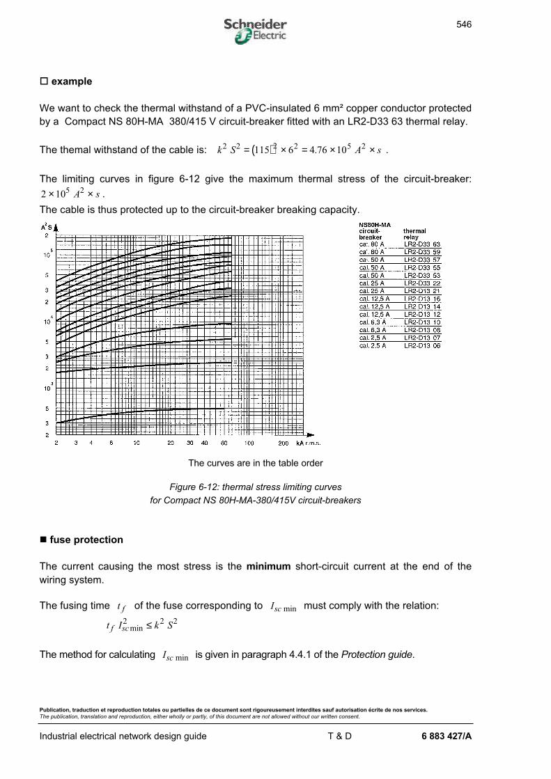
o example
We want to check the thermal withstand of a PVC-insulated 6 mm² copper conductor protected
by a Compact NS 80H-MA 380/415 V circuit-breaker fitted with an LR2-D33 63 thermal relay.
The themal withstand of the cable is: ( )k S A s2 2 2 2 5 2115 6 4 76 10= × = × ×. .
The limiting curves in figure 6-12 give the maximum thermal stress of the circuit-breaker:
2 105 2× ×A s .
The cable is thus protected up to the circuit-breaker breaking capacity.
The curves are in the table order
Figure 6-12: thermal stress limiting curves
for Compact NS 80H-MA-380/415V circuit-breakers
n fuse protection
The current causing the most stress is the minimum short-circuit current at the end of the
wiring system.
The fusing time t f of the fuse corresponding to Isc min must comply with the relation:
t I k Sf scmin2 2 2≤
The method for calculating Isc min is given in paragraph 4.4.1 of the Protection guide.
547
Publication, traduction et reproduction totales ou partielles de ce document sont rigoureusement interdites sauf autorisation écrite de nos services.
The publication, translation and reproduction, either wholly or partly, of this document are not allowed without our written consent.
Industrial electrical network design guide T & D 6 883 427/A
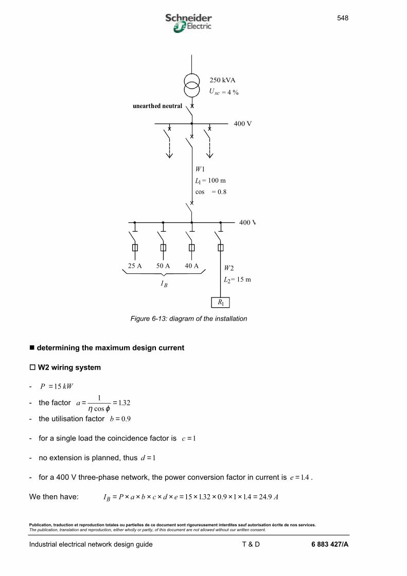
6.1.10. Application example
n hypotheses
Let us consider the diagram in figure 6-13 the data of which is given below.
Since the installation feeds loads requiring good continuity of service the IT earthing system
without distributed neutral is chosen.
o W2 wiring system
This is made up of a PVC insulated copper three-core cable which is installed touching 3 other
multi-core cables on perforated trays in an ambient temperature of 40°C. It is protected by
fuses. It feeds a load having the following characteristics:
- active power P kW=15
- efficiency η = 0 89.
- cos .ϕ = 0 85
- utilisation factor b = 0 9. .
o W1 wiring system
This is made up of 3 XLPE-insulated copper single-core cables in a triangular formation. The
cables are buried alone, without any extra mechanical protection, in soil which has a thermal
resistivity of 0.85 K.m/W and a temperature of 35 °C. They are protected by a circuit-breaker.
The wiring system feeds load L1 and 3 other outgoing feeders the IB current values of which
are given in figure 6-13.
548
Publication, traduction et reproduction totales ou partielles de ce document sont rigoureusement interdites sauf autorisation écrite de nos services.
The publication, translation and reproduction, either wholly or partly, of this document are not allowed without our written consent.
Industrial electrical network design guide T & D 6 883 427/A
250 kVA
= 4 %
400 V
= 100 m
cos = 0.8
400 V
I B
25 A 50 A 40 A
= 15 m
L1
R1
L2
unearthed neutral
U sc
W1
W2
Figure 6-13: diagram of the installation
n determining the maximum design current
o W2 wiring system
- P kW=15
- the factor a = =1
132η ϕcos
.
- the utilisation factor b = 0 9.
- for a single load the coincidence factor is c =1
- no extension is planned, thus d =1
- for a 400 V three-phase network, the power conversion factor in current is e =1.4 .
We then have: I P a b c d e AB = × × × × × = × × × × =15 132 0 9 1 1 24 9. . .4 .
549
Publication, traduction et reproduction totales ou partielles de ce document sont rigoureusement interdites sauf autorisation écrite de nos services.
The publication, translation and reproduction, either wholly or partly, of this document are not allowed without our written consent.
Industrial electrical network design guide T & D 6 883 427/A
o W1 wiring system
The maximum design current of the W1 wiring system is obtained by calculating the sum of
currents ( )IB of all the outgoing feeders fed by W1 and by applying a coincidence factor
estimated at 0.8 (see table 6-2):
( )I AB = + + + × =25 50 40 24 9 0 8 115 9. . .
n correction factors
o W2 wiring system
Table 6-3 gives the installation method N° 13 and the selection letter E .
The correction factors to be applied are:
- ambient temperature (see table 6-6) : f1 = 0.87
- cable group (see tables 6-9 et 6-10) : f4 = 0.77 and f5 = 1
The overall correction factor is:
f = × × =0 87 0 77 1 0 67. . .
o W1 wiring system
Table 6-3 gives the installation method N° 62 and the selection letter D .
The correction factors to be applied are:
- ground temperature (see table 6-7) : f2 = 0.89
- soil thermal resistivity (see table 6-8) : f3 = 1.05
- cable group (see table 6-15) : f10 = 1
The overall correction factor is:
f = × × =0 89 1 05 1 0 935. . .
550
Publication, traduction et reproduction totales ou partielles de ce document sont rigoureusement interdites sauf autorisation écrite de nos services.
The publication, translation and reproduction, either wholly or partly, of this document are not allowed without our written consent.
Industrial electrical network design guide T & D 6 883 427/A
n determining the cross-sectional area and choosing the protective device
o W2 wiring system
I AB = 24 9.
f = 0 67.
The fuse nominal current must comply with the condition I In B≥ .
The fuse with a rating of I An = 25 is chosen.
For 10 25A In< ≤ A , the current Iz of the wiring system protected by this fuse is:
I k I I Az n n= = =3 1 21 30 3. .
The equivalent current that the wiring system must be able to carry in standard installation
conditions is: II
fAz
z'.= = 451
Table 6-16 (selection letter E , PVC3, copper) gives a minimum cross-sectional area of
S mm= 10 2 which has a current-carrying capacity of I A0 60= .
o W1 wiring system
I AB =115 9.
f = 0 935.
For an adjustable circuit-breaker, the setting current must comply with the condition I Iset B≥ ;
I Aset =120 is chosen.
The current Iz of the wiring system protected by this setting is:
I I Az n= = 120
The equivalent current that the wiring system must be able to carry in standard installation
conditions is: II
fAz
z'.= =128 3
Table 6-17 (selection letter D , XLPE3, copper) gives a minimum cross-sectional area of
S mm= 25 2 which has a current-carrying capacity of I A0 144= .
551
Publication, traduction et reproduction totales ou partielles de ce document sont rigoureusement interdites sauf autorisation écrite de nos services.
The publication, translation and reproduction, either wholly or partly, of this document are not allowed without our written consent.
Industrial electrical network design guide T & D 6 883 427/A
n maximum length of the wiring system
o W2 wiring system
For S mmph = 10 ² , we have S S mmPE ph= = 10 ²
whence mS
S
ph
PE
= =1
Table 6-20 gives a maximum disconnecting time of t s= 0.4 for a network with non-distributed neutral.
The time-current characteristic for a 25 A rated fuse gives us a current of I Aa = 200 for a
disconnecting time of 0.4 s.
The neutral is not distributed and we thus have:
( )LV S
m Im
n ph
amax
. .
..=
× × ×+
=× × ×
× × ×=
0 8 3
2 1
0 8 3 230 10
2 0 027 2 200147 5
ρ
The length of the W2 wiring system (15 m) is far smaller than Lmax and the protection of
persons against indirect contact is thus ensured.
o W1 wiring system
For 16 35mm S mm² ²< ≤ , we have S mmPE =16 ²
whence mS
S
ph
PE
= = =25
16156.
The circuit-breaker chosen is a Compact NS 125E with an STR 22SE trip relay having a
magnetic tripping threshold set at Im = 1 250 A because of the selectivity.
The neutral is not distributed and we thus have:
( )LV S
m Im
n ph
mmax
. .
. ..=
× × ×+
=× × ×
× × ×=
0 8 3
2 1
0 8 3 230 25
2 0 027 2 56 1250461
ρ
The length of the W1 wiring system (100 m) is greater than Lmax .
By taking cross-sectional areas greater, i.e. S mmph = 35 ² and S mm mPE = =35 1² ( ) , we find
L m mmax .= <82 6 100 ; which is not sufficient.
So as not to oversize the conductors, it is decided that the outgoing feeder should be fitted
with a residual current device which ensures the protection of persons against indirect contact.
552
Publication, traduction et reproduction totales ou partielles de ce document sont rigoureusement interdites sauf autorisation écrite de nos services.
The publication, translation and reproduction, either wholly or partly, of this document are not allowed without our written consent.
Industrial electrical network design guide T & D 6 883 427/A
n checking the voltage drop
o W2 wiring system
S = 10 mm² , L = 15 m , IB = 24.9 A
The cable is three-core and we thus have λ = × −0 08 10 3. /Ω m .
The power factor is cos .ϕ = 0 85 , whence sin .ϕ = 0 53 .
For a three-phase circuit b = 1 .
For copper ρ120 0225= . /Ωmm m .
We deduce from this that ∆ V = × × + × × ×
×−
0 022515
100 85 0 08 10 15 0 53 24 9
3. . . . .
∆ V V= 0 73.
whence∆ V
Vn
= =0 73
2300 3
.. %
The total voltage drop is 4.2 % (the voltage drop in the W1 wiring system is 3.9 %, see below).
o W1 wiring system
S = 25 mm² , L = 100 m , IB = 115.9 A
The 3 single-core cables are in a flat formation and we thus have:
λ = × −0 09 10 3. /Ω m
The overall power factor of the installation is cos .ϕ = 0 8 , whence sin .ϕ = 0 6 .
We deduce from this that ∆ V = × × + × × ×
×−
0 0225100
250 8 0 09 10 100 0 6 115 9
3. . . . .
∆ V V= 8 97.
whence∆ V
Vn
= =8 97
2303 9
.. %
553
Publication, traduction et reproduction totales ou partielles de ce document sont rigoureusement interdites sauf autorisation écrite de nos services.
The publication, translation and reproduction, either wholly or partly, of this document are not allowed without our written consent.
Industrial electrical network design guide T & D 6 883 427/A
n checking the thermal stress
o W2 wiring system
For fuse protection, the current to be taken into account is the minimum short-circuit current at
the end of the wiring system. For the IT earthing system, this is the short-circuit current for a
double phase-earth fault.
By applying the conventional method (see § 4.4.1.2 of the Protection guide), we can calculate:
IV
LS S
kAscn
ph PE
min. .
.
.= × ×
+
= × ×
× × +
=3 0 8
21 1
3 230 0 8
2 15 0 0271
10
1
10
197
2 ρ
The time-current characteristic of the 25 A rated fuse gives us a fusing time of t msf = 5 for a
current of 1.97 kA.
The maximum thermal stress is thus:
( )I t A sscmin . .42 3 2 3 3 2
197 10 5 10 19 10× = × × × = × ×−
The permitted cable thermal withstand is: ( )k S A s2 2 2 2 3 2115 10 1322 10= × = × × .
The cross-sectional area of S mm= 10 2 is thus largely able to withstand to the fuse thermal
stress.
o W1 wiring system
The maximum short-circuit current of the circuit-breaker (neglecting the connection linking the
circuit-breaker to the transformer) is:
IS
U UkAsc
n
n sc
= × =××
× =3
1 250 10
3 400
100
49 02
3
.
We assume that the circuit-breaker trip relay is delayed by 0.1 second, the maximum short-
circuit thermal stress is then:
( )I t A ssc2 3 2 6 2
9 02 10 0 1 814 10= × × = × ×. . .
The permitted cable thermal withstand is: k S A s2 2 2 2 6 2143 25 12 78 10× = × = × ×.
The cross-sectional area of S mm= 25 2 is thus largely able to withstand the circuit-breaker
thermal stress.
554
Publication, traduction et reproduction totales ou partielles de ce document sont rigoureusement interdites sauf autorisation écrite de nos services.
The publication, translation and reproduction, either wholly or partly, of this document are not allowed without our written consent.
Industrial electrical network design guide T & D 6 883 427/A
n conclusion
The cross-sectional areas to be chosen are:
- W1 wiring system: 3 35 1 162 2× + ×mm mm copper
- W2 wiring system: 3 10 1 102 2× + ×mm mm copper
555
Publication, traduction et reproduction totales ou partielles de ce document sont rigoureusement interdites sauf autorisation écrite de nos services.
The publication, translation and reproduction, either wholly or partly, of this document are not allowed without our written consent.
Industrial electrical network design guide T & D 6 883 427/AE
6.2. Determining conductor cross-sectional areas in medium voltage
6.2.1. Method principle
The method for determining the cross-sectional area of conductors in medium voltage consists
in:
- determining the maximum design current IB of the loads to be supplied
- determining the cross-sectional area S1 complying with the heating of the cable core under
normal operating conditions, which may be continuous or discontinuous. To do this, it is
necessary to know:
. the actual installation conditions of the wiring system and consequently the overall
correction factor f
. the current-carrying capacities of the different types of cable in standard installation
conditions.
- determining the cross-sectional area S2 required for the thermal withstand of the cable in
the event of a three-phase short circuit
- determining the cross-sectional area S3 required for the thermal withstand of the cable
screen in the event of an earth fault
- possibly checking the voltage drop in the wiring system for the chosen cross-sectional
area S. The technical cross-sectional area S to be selected is the maximum value among
cross-sectional areas S1 , S2 and S3 .
- possibly calculating and choosing the economical cross-sectional area.
6.2.2. Determining the maximum design current
The maximum design current IB is determined on the basis of the sum of powers of the loads
fed, applying if necessary utilisation and coincidence coefficients (see § 6.1.2.).
In medium voltage, a wiring system most often feeds a single load (transformer, motor,
furnace, steam generator), in this case IB is taken to be equal to the rated current of the
device.
556
Publication, traduction et reproduction totales ou partielles de ce document sont rigoureusement interdites sauf autorisation écrite de nos services.
The publication, translation and reproduction, either wholly or partly, of this document are not allowed without our written consent.
Industrial electrical network design guide T & D 6 883 427/AE
6.2.3. Current-carrying capacities in wiring systems
n general rules
The current-carrying capacity is the maximum current that a wiring system can continuously
carry without this affecting its life span.
The current-carrying capacities of cables are given in standards or by manufacturers for
standard installation conditions.
To determine the current-carrying capacity of a wiring system in actual installation conditions,
the following must be carried out:
- using table 6-23, define the installation method, its associated table column number and
correction factors to be applied
- using the installation conditions, determine the correction factor values which must be
applied (see tables 6-24 to 6-28)
- calculate the overall correction factor f equal to the product of the correction factors
- using table 6-29 for impregnated paper-insulated cables and tables 6-30 to 6-34 for
synthetically-insulated cables, determine the maximum current that the wiring system can
carry in standard conditions ( )f f0 6 1to =
- calculate the maximum current-carrying capacity of the wiring system in relation to its
installation conditions: I f Ia = 0 .
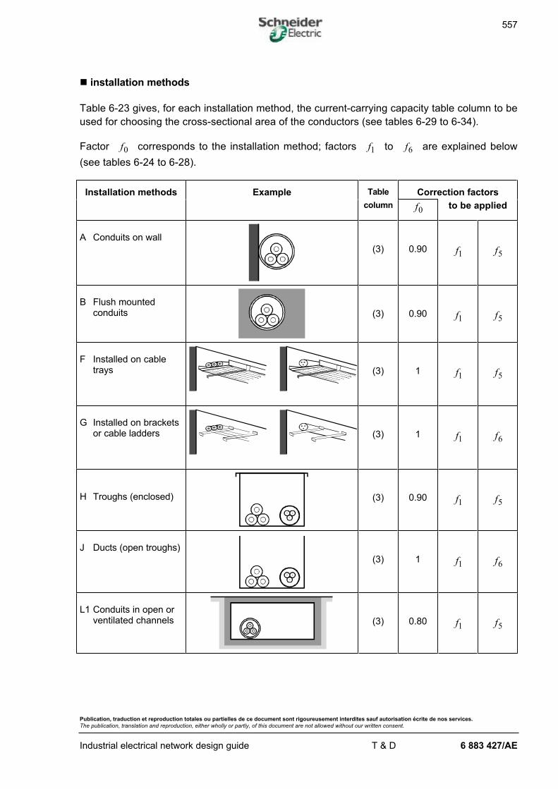
557
Publication, traduction et reproduction totales ou partielles de ce document sont rigoureusement interdites sauf autorisation écrite de nos services.
The publication, translation and reproduction, either wholly or partly, of this document are not allowed without our written consent.
Industrial electrical network design guide T & D 6 883 427/AE
n installation methods
Table 6-23 gives, for each installation method, the current-carrying capacity table column to be
used for choosing the cross-sectional area of the conductors (see tables 6-29 to 6-34).
Factor f0 corresponds to the installation method; factors f1 to f6 are explained below
(see tables 6-24 to 6-28).
Installation methods Example Table Correction factors
column f0 to be applied
A Conduits on wall
(3) 0.90 f1 f5
B Flush mountedconduits (3) 0.90 f1 f5
F Installed on cabletrays (3) 1 f1 f5
G Installed on bracketsor cable ladders (3) 1 f1 f6
H Troughs (enclosed) (3) 0.90 f1 f5
J Ducts (open troughs)
(3) 1 f1 f6
L1 Conduits in open orventilated channels (3) 0.80 f1 f5
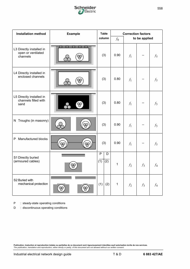
558
Publication, traduction et reproduction totales ou partielles de ce document sont rigoureusement interdites sauf autorisation écrite de nos services.
The publication, translation and reproduction, either wholly or partly, of this document are not allowed without our written consent.
Industrial electrical network design guide T & D 6 883 427/AE
Installation method Example Table Correction factors
column f0 to be applied
L3 Directly installed inopen or ventilatedchannels (3) 0.90 f1 -- f5
L4 Directly installed inenclosed channels
(3) 0.80 f1 -- f5
L5 Directly installed inchannels filled withsand (3) 0.80 f1 -- f5
N Troughs (in masonry)
(3) 0.90 f1 -- f5
P Manufactured blocks
(3) 0.90 f1 -- f5
S1 Directly buried(armoured cables)
P___
(1)
D____ (2)
1 f2 f3 f4
S2 Buried withmechanical protection (1) (2) 1 f2 f3 f4
P : steady-state operating conditions
D : discontinuous operating conditions
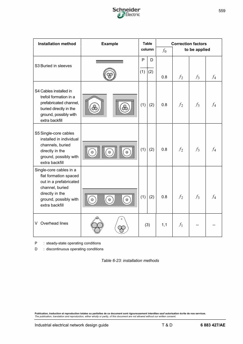
559
Publication, traduction et reproduction totales ou partielles de ce document sont rigoureusement interdites sauf autorisation écrite de nos services.
The publication, translation and reproduction, either wholly or partly, of this document are not allowed without our written consent.
Industrial electrical network design guide T & D 6 883 427/AE
Installation method Example Table Correction factors
column f0 to be applied
S3 Buried in sleeves
P
____
(1)
D
___
(2)
0.8 f2 f3 f4
S4 Cables installed in
trefoil formation in a
prefabricated channel,
buried directly in the
ground, possibly with
extra backfill
(1) (2) 0.8 f2 f3 f4
S5 Single-core cables
installed in individual
channels, buried
directly in the
ground, possibly with
extra backfill
(1) (2) 0.8 f2 f3 f4
Single-core cables in a
flat formation spaced
out in a prefabricated
channel, buried
directly in the
ground, possibly with
extra backfill
(1) (2) 0.8 f2 f3 f4
V Overhead lines (3) 1,1 f1 -- --
P : steady-state operating conditions
D : discontinuous operating conditions
Table 6-23: installation methods
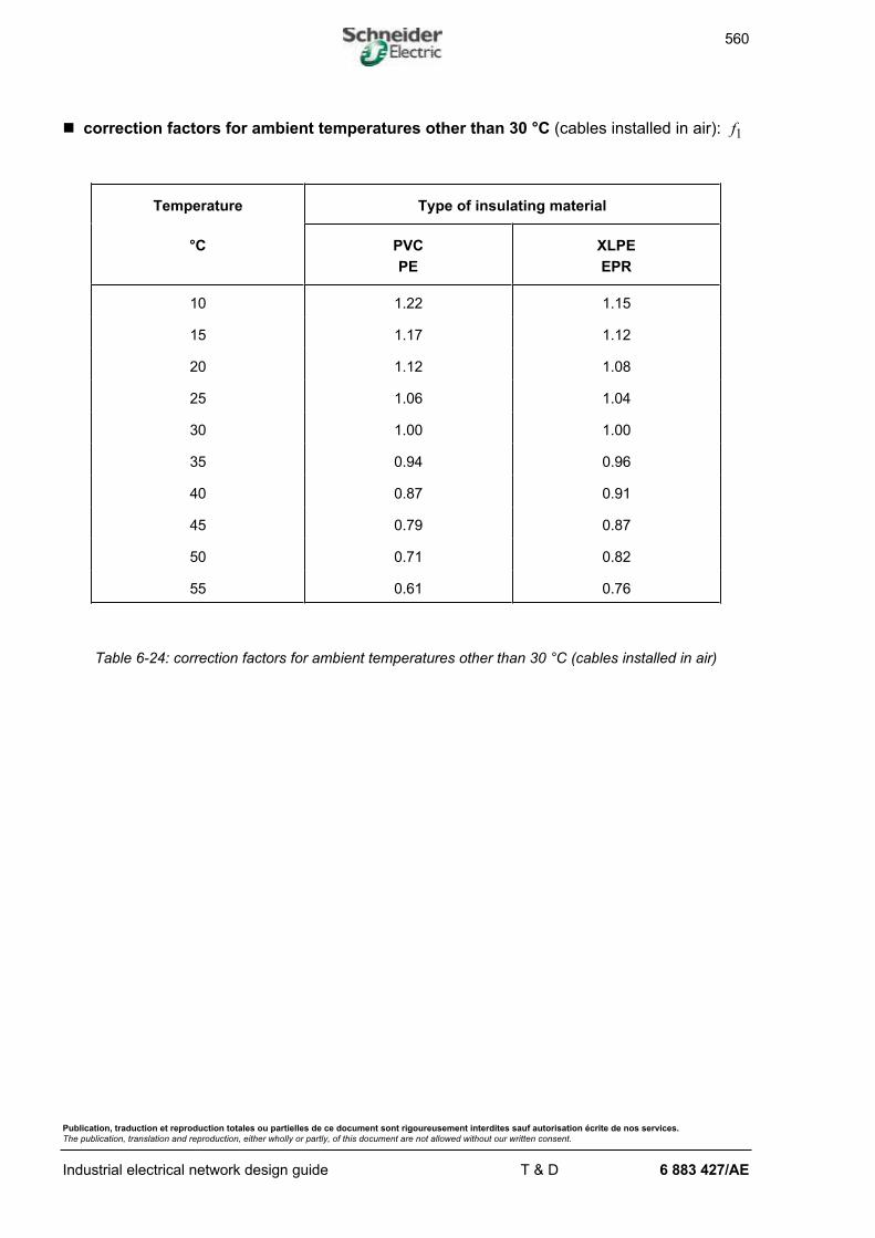
560
Publication, traduction et reproduction totales ou partielles de ce document sont rigoureusement interdites sauf autorisation écrite de nos services.
The publication, translation and reproduction, either wholly or partly, of this document are not allowed without our written consent.
Industrial electrical network design guide T & D 6 883 427/AE
n correction factors for ambient temperatures other than 30 °C (cables installed in air): f1
Temperature Type of insulating material
°C PVC
PE
XLPE
EPR
10 1.22 1.15
15 1.17 1.12
20 1.12 1.08
25 1.06 1.04
30 1.00 1.00
35 0.94 0.96
40 0.87 0.91
45 0.79 0.87
50 0.71 0.82
55 0.61 0.76
Table 6-24: correction factors for ambient temperatures other than 30 °C (cables installed in air)
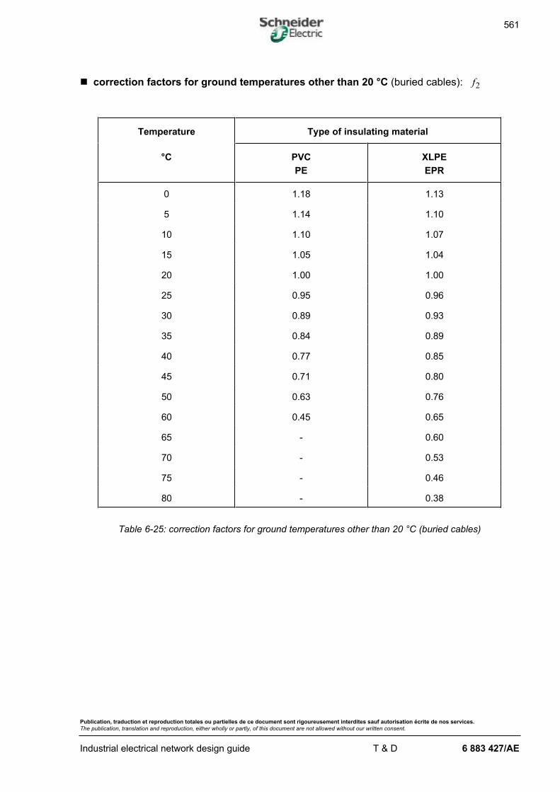
561
Publication, traduction et reproduction totales ou partielles de ce document sont rigoureusement interdites sauf autorisation écrite de nos services.
The publication, translation and reproduction, either wholly or partly, of this document are not allowed without our written consent.
Industrial electrical network design guide T & D 6 883 427/AE
n correction factors for ground temperatures other than 20 °C (buried cables): f2
Temperature Type of insulating material
°C PVC
PE
XLPE
EPR
0 1.18 1.13
5 1.14 1.10
10 1.10 1.07
15 1.05 1.04
20 1.00 1.00
25 0.95 0.96
30 0.89 0.93
35 0.84 0.89
40 0.77 0.85
45 0.71 0.80
50 0.63 0.76
60 0.45 0.65
65 - 0.60
70 - 0.53
75 - 0.46
80 - 0.38
Table 6-25: correction factors for ground temperatures other than 20 °C (buried cables)
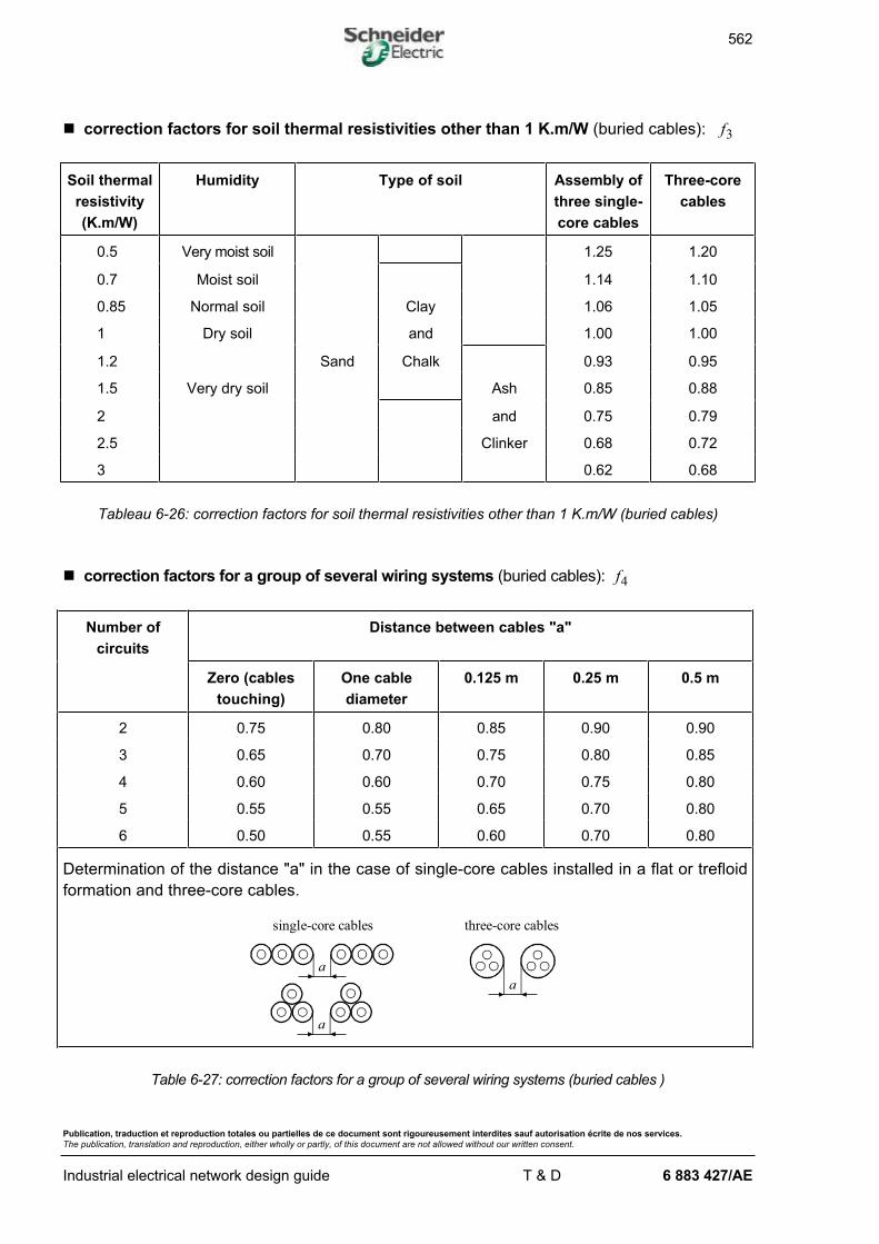
562
Publication, traduction et reproduction totales ou partielles de ce document sont rigoureusement interdites sauf autorisation écrite de nos services.
The publication, translation and reproduction, either wholly or partly, of this document are not allowed without our written consent.
Industrial electrical network design guide T & D 6 883 427/AE
n correction factors for soil thermal resistivities other than 1 K.m/W (buried cables): f3
Soil thermal
resistivity
(K.m/W)
Humidity Type of soil Assembly of
three single-
core cables
Three-core
cables
0.5 Very moist soil 1.25 1.20
0.7 Moist soil 1.14 1.10
0.85 Normal soil Clay 1.06 1.05
1 Dry soil and 1.00 1.00
1.2 Sand Chalk 0.93 0.95
1.5 Very dry soil Ash 0.85 0.88
2 and 0.75 0.79
2.5 Clinker 0.68 0.72
3 0.62 0.68
Tableau 6-26: correction factors for soil thermal resistivities other than 1 K.m/W (buried cables)
n correction factors for a group of several wiring systems (buried cables): f4
Number of
circuits
Distance between cables "a"
Zero (cables
touching)
One cable
diameter
0.125 m 0.25 m 0.5 m
2 0.75 0.80 0.85 0.90 0.90
3 0.65 0.70 0.75 0.80 0.85
4 0.60 0.60 0.70 0.75 0.80
5 0.55 0.55 0.65 0.70 0.80
6 0.50 0.55 0.60 0.70 0.80
Determination of the distance "a" in the case of single-core cables installed in a flat or trefloid
formation and three-core cables.
single-core cables three-core cables
a
a
a
Table 6-27: correction factors for a group of several wiring systems (buried cables )
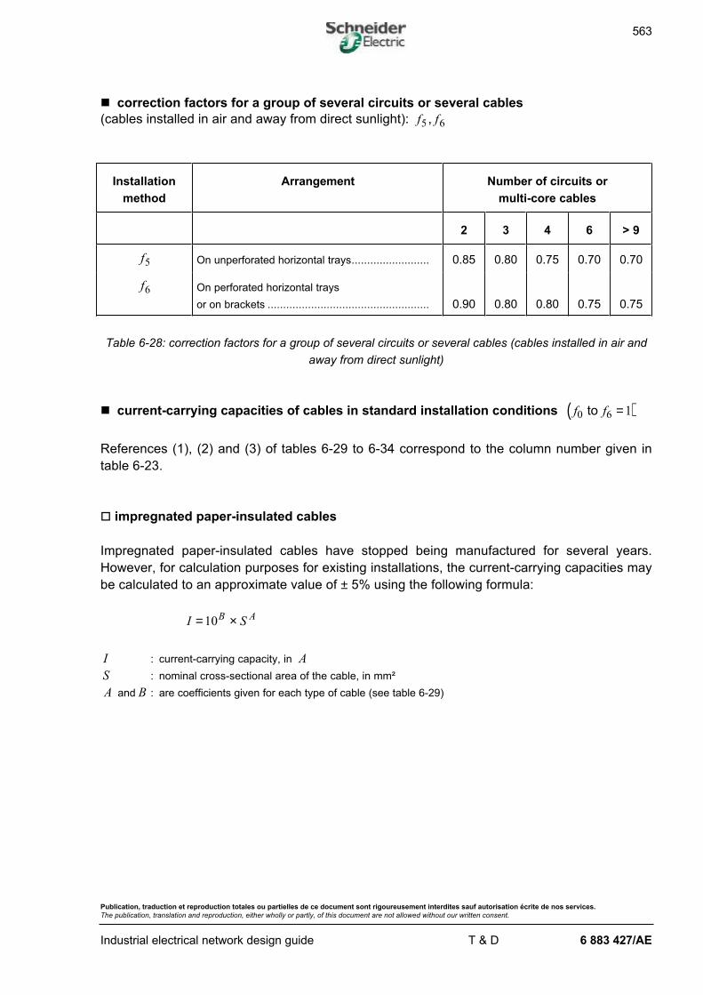
563
Publication, traduction et reproduction totales ou partielles de ce document sont rigoureusement interdites sauf autorisation écrite de nos services.
The publication, translation and reproduction, either wholly or partly, of this document are not allowed without our written consent.
Industrial electrical network design guide T & D 6 883 427/AE
n correction factors for a group of several circuits or several cables
(cables installed in air and away from direct sunlight): f f5 6,
Installation
method
Arrangement Number of circuits or
multi-core cables
2 3 4 6 > 9
f5 On unperforated horizontal trays......................... 0.85 0.80 0.75 0.70 0.70
f6 On perforated horizontal trays
or on brackets .................................................... 0.90 0.80 0.80 0.75 0.75
Table 6-28: correction factors for a group of several circuits or several cables (cables installed in air and
away from direct sunlight)
n current-carrying capacities of cables in standard installation conditions ( )f f0 6 1to =
References (1), (2) and (3) of tables 6-29 to 6-34 correspond to the column number given in
table 6-23.
o impregnated paper-insulated cables
Impregnated paper-insulated cables have stopped being manufactured for several years.
However, for calculation purposes for existing installations, the current-carrying capacities may
be calculated to an approximate value of ± 5% using the following formula:
I SB A= ×10
I : current-carrying capacity, in A
S : nominal cross-sectional area of the cable, in mm²
A and B : are coefficients given for each type of cable (see table 6-29)
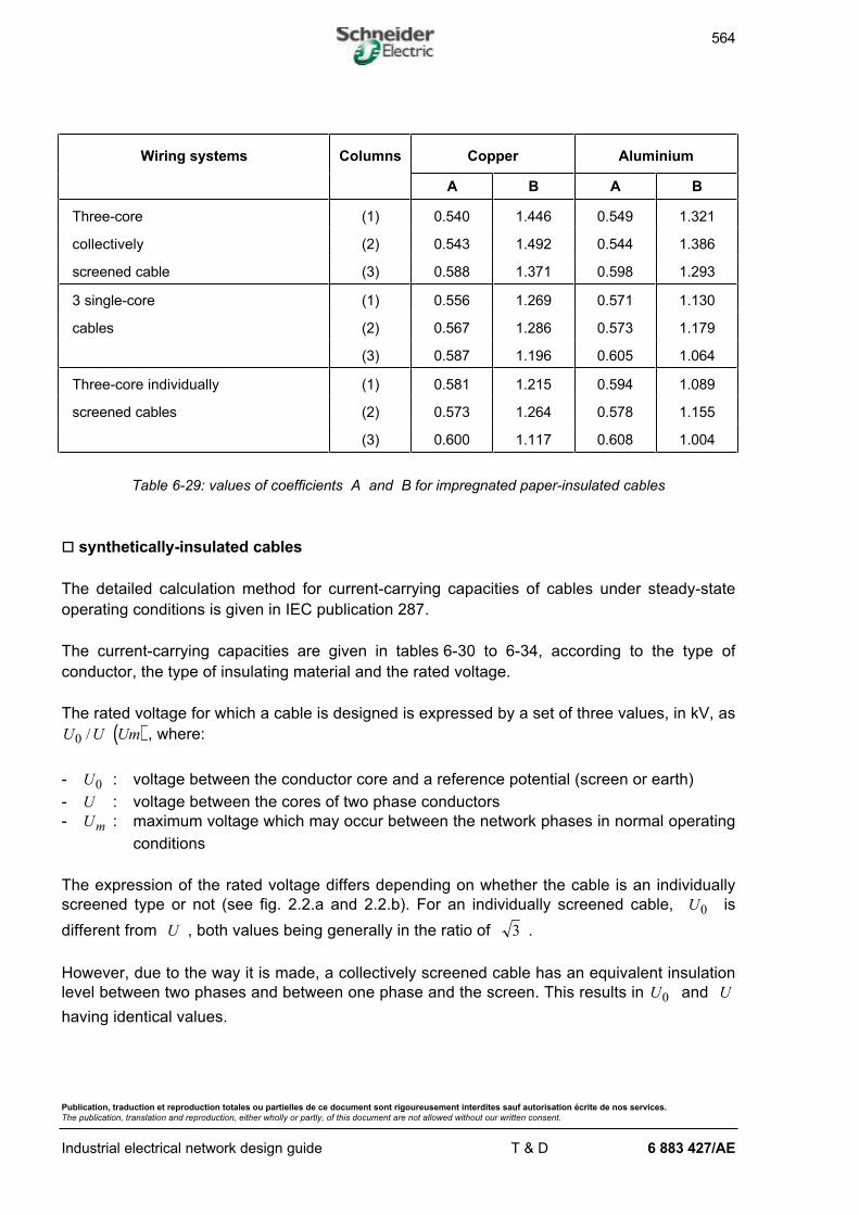
564
Publication, traduction et reproduction totales ou partielles de ce document sont rigoureusement interdites sauf autorisation écrite de nos services.
The publication, translation and reproduction, either wholly or partly, of this document are not allowed without our written consent.
Industrial electrical network design guide T & D 6 883 427/AE
Wiring systems Columns Copper Aluminium
A B A B
Three-core (1) 0.540 1.446 0.549 1.321
collectively (2) 0.543 1.492 0.544 1.386
screened cable (3) 0.588 1.371 0.598 1.293
3 single-core (1) 0.556 1.269 0.571 1.130
cables (2) 0.567 1.286 0.573 1.179
(3) 0.587 1.196 0.605 1.064
Three-core individually (1) 0.581 1.215 0.594 1.089
screened cables (2) 0.573 1.264 0.578 1.155
(3) 0.600 1.117 0.608 1.004
Table 6-29: values of coefficients A and B for impregnated paper-insulated cables
o synthetically-insulated cables
The detailed calculation method for current-carrying capacities of cables under steady-state
operating conditions is given in IEC publication 287.
The current-carrying capacities are given in tables 6-30 to 6-34, according to the type of
conductor, the type of insulating material and the rated voltage.
The rated voltage for which a cable is designed is expressed by a set of three values, in kV, as
( )U U Um0 / , where:
- U0 : voltage between the conductor core and a reference potential (screen or earth)
- U : voltage between the cores of two phase conductors
- Um : maximum voltage which may occur between the network phases in normal operating
conditions
The expression of the rated voltage differs depending on whether the cable is an individually
screened type or not (see fig. 2.2.a and 2.2.b). For an individually screened cable, U0 is
different from U , both values being generally in the ratio of 3 .
However, due to the way it is made, a collectively screened cable has an equivalent insulation
level between two phases and between one phase and the screen. This results in U0 and U
having identical values.

565
Publication, traduction et reproduction totales ou partielles de ce document sont rigoureusement interdites sauf autorisation écrite de nos services.
The publication, translation and reproduction, either wholly or partly, of this document are not allowed without our written consent.
Industrial electrical network design guide T & D 6 883 427/AE
PVC-insulated Nominal
cross-
sectional
area (mm²)*
EPR or XLPE-insulated
(1) (2) (3) Copper (1) (2) (3)
72
94
120
145
185
225
270
310
345
385
445
78
100
130
160
205
250
300
345
390
430
500
62
81
105
130
165
205
250
290
330
370
440
10
16
25
35
50
70
95
120
150
185
240
86
110
145
170
215
260
315
360
405
450
525
94
120
155
190
240
295
355
405
455
505
590
78
100
130
165
205
255
310
360
410
460
550
(1) (2) (3) Aluminium (1) (2) (3)
56
72
94
115
145
175
210
240
270
300
350
61
79
100
125
160
195
235
270
300
335
390
48
62
82
100
130
160
195
225
255
285
345
10
16
25
35
50
70
95
120
150
185
240
67
86
110
135
165
205
245
280
315
350
410
73
94
120
145
185
230
275
315
355
395
460
60
79
105
125
160
195
240
280
320
360
430
(*) Above 50 mm², the values are calculated for sector conductors
Table 6-30: current-carrying capacities in three-core collectively screened cables having a rated voltage
lower than or equal to 6/6 (7.2) kV
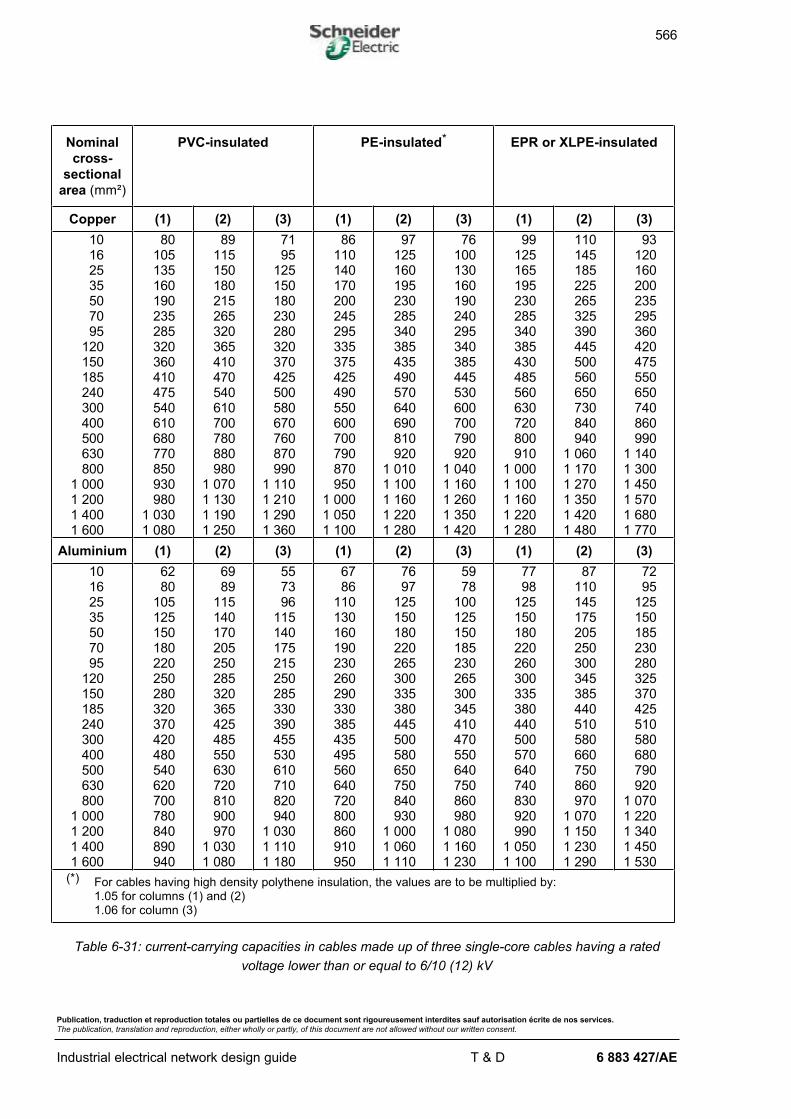
566
Publication, traduction et reproduction totales ou partielles de ce document sont rigoureusement interdites sauf autorisation écrite de nos services.
The publication, translation and reproduction, either wholly or partly, of this document are not allowed without our written consent.
Industrial electrical network design guide T & D 6 883 427/AE
Nominal
cross-
sectional
area (mm²)
PVC-insulated PE-insulated* EPR or XLPE-insulated
Copper (1) (2) (3) (1) (2) (3) (1) (2) (3)
10162535507095
120150185240300400500630800
1 0001 2001 4001 600
80105135160190235285320360410475540610680770850930980
1 0301 080
89115150180215265320365410470540610700780880980
1 0701 1301 1901 250
7195
125150180230280320370425500580670760870990
1 1101 2101 2901 360
86110140170200245295335375425490550600700790870950
1 0001 0501 100
97125160195230285340385435490570640690810920
1 0101 1001 1601 2201 280
76100130160190240295340385445530600700790920
1 0401 1601 2601 3501 420
99125165195230285340385430485560630720800910
1 0001 1001 1601 2201 280
110145185225265325390445500560650730840940
1 0601 1701 2701 3501 4201 480
93120160200235295360420475550650740860990
1 1401 3001 4501 5701 6801 770
Aluminium (1) (2) (3) (1) (2) (3) (1) (2) (3)
10162535507095
120150185240300400500630800
1 0001 2001 4001 600
6280
105125150180220250280320370420480540620700780840890940
6989
115140170205250285320365425485550630720810900970
1 0301 080
557396
115140175215250285330390455530610710820940
1 0301 1101 180
6786
110130160190230260290330385435495560640720800860910950
7697
125150180220265300335380445500580650750840930
1 0001 0601 110
5978
100125150185230265300345410470550640750860980
1 0801 1601 230
7798
125150180220260300335380440500570640740830920990
1 0501 100
87110145175205250300345385440510580660750860970
1 0701 1501 2301 290
7295
125150185230280325370425510580680790920
1 0701 2201 3401 4501 530
(*) For cables having high density polythene insulation, the values are to be multiplied by:1.05 for columns (1) and (2)1.06 for column (3)
Table 6-31: current-carrying capacities in cables made up of three single-core cables having a rated
voltage lower than or equal to 6/10 (12) kV
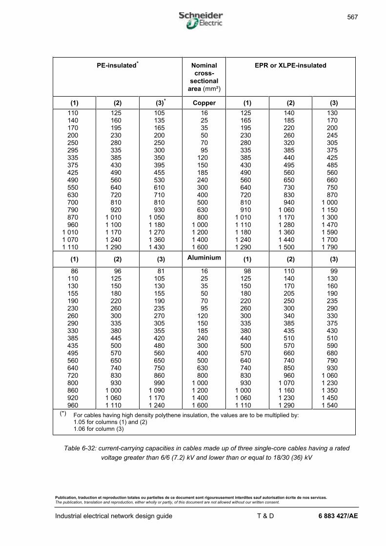
567
Publication, traduction et reproduction totales ou partielles de ce document sont rigoureusement interdites sauf autorisation écrite de nos services.
The publication, translation and reproduction, either wholly or partly, of this document are not allowed without our written consent.
Industrial electrical network design guide T & D 6 883 427/AE
PE-insulated* Nominal
cross-
sectional
area (mm²)
EPR or XLPE-insulated
(1) (2) (3)* Copper (1) (2) (3)
110140170200250295335375425490550630700790870960
1 0101 0701 110
125160195230280335385430490560640720810920
1 0101 1001 1701 2401 290
105135165200250300350395455530610710810930
1 0501 1801 2701 3601 430
162535507095
120150185240300400500630800
1 0001 2001 4001 600
125165195230280335385430490560640720810910
1 0101 1101 1801 2401 290
140185220260320385440495560650730830940
1 0601 1701 2801 3601 4401 500
130170200245305375425485560660750870
1 0001 1501 3001 4701 5901 7001 790
(1) (2) (3) Aluminium (1) (2) (3)
86110130155190230260290330385435495560640720800860920960
96125150180220260300335380445500570650740830930
1 0001 0601 110
81105130155190235270305355420480560650750860990
1 0901 1701 240
162535507095
120150185240300400500630800
1 0001 2001 4001 600
98125150180220260300335380440500570640740830930
1 0001 0601 110
110140170205250300340385435510570660740850960
1 0701 1601 2301 290
99130160190235290330375430510590680790930
1 0601 2301 3501 4501 540
(*) For cables having high density polythene insulation, the values are to be multiplied by:1.05 for columns (1) and (2)1.06 for column (3)
Table 6-32: current-carrying capacities in cables made up of three single-core cables having a rated
voltage greater than 6/6 (7.2) kV and lower than or equal to 18/30 (36) kV
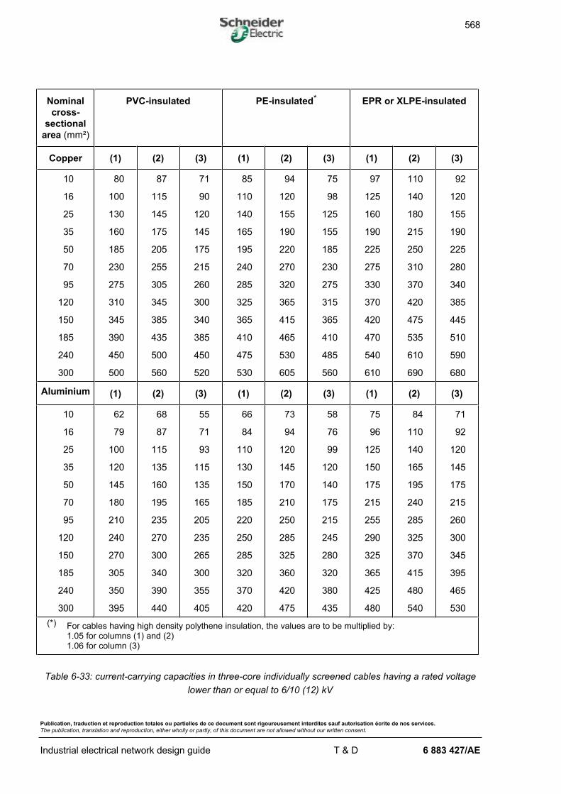
568
Publication, traduction et reproduction totales ou partielles de ce document sont rigoureusement interdites sauf autorisation écrite de nos services.
The publication, translation and reproduction, either wholly or partly, of this document are not allowed without our written consent.
Industrial electrical network design guide T & D 6 883 427/AE
Nominal
cross-
sectional
area (mm²)
PVC-insulated PE-insulated* EPR or XLPE-insulated
Copper (1) (2) (3) (1) (2) (3) (1) (2) (3)
10
16
25
35
50
70
95
120
150
185
240
300
80
100
130
160
185
230
275
310
345
390
450
500
87
115
145
175
205
255
305
345
385
435
500
560
71
90
120
145
175
215
260
300
340
385
450
520
85
110
140
165
195
240
285
325
365
410
475
530
94
120
155
190
220
270
320
365
415
465
530
605
75
98
125
155
185
230
275
315
365
410
485
560
97
125
160
190
225
275
330
370
420
470
540
610
110
140
180
215
250
310
370
420
475
535
610
690
92
120
155
190
225
280
340
385
445
510
590
680
Aluminium (1) (2) (3) (1) (2) (3) (1) (2) (3)
10
16
25
35
50
70
95
120
150
185
240
300
62
79
100
120
145
180
210
240
270
305
350
395
68
87
115
135
160
195
235
270
300
340
390
440
55
71
93
115
135
165
205
235
265
300
355
405
66
84
110
130
150
185
220
250
285
320
370
420
73
94
120
145
170
210
250
285
325
360
420
475
58
76
99
120
140
175
215
245
280
320
380
435
75
96
125
150
175
215
255
290
325
365
425
480
84
110
140
165
195
240
285
325
370
415
480
540
71
92
120
145
175
215
260
300
345
395
465
530
(*) For cables having high density polythene insulation, the values are to be multiplied by:1.05 for columns (1) and (2)1.06 for column (3)
Table 6-33: current-carrying capacities in three-core individually screened cables having a rated voltage
lower than or equal to 6/10 (12) kV
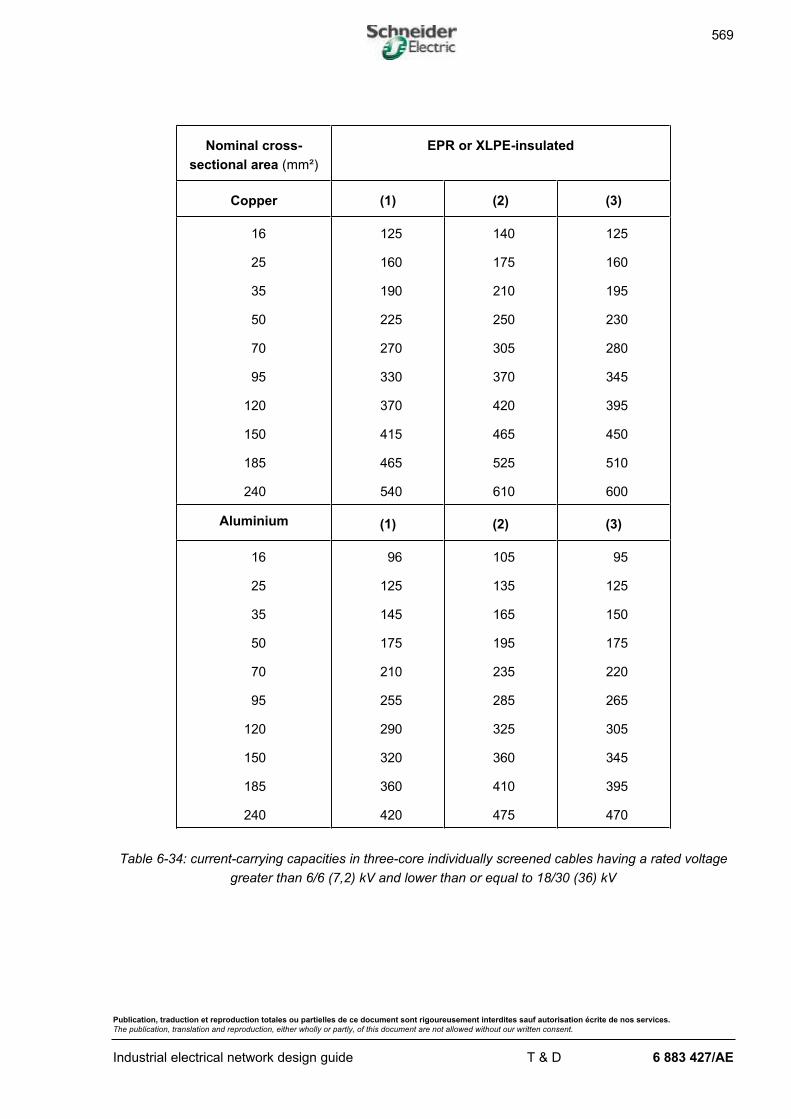
569
Publication, traduction et reproduction totales ou partielles de ce document sont rigoureusement interdites sauf autorisation écrite de nos services.
The publication, translation and reproduction, either wholly or partly, of this document are not allowed without our written consent.
Industrial electrical network design guide T & D 6 883 427/AE
Nominal cross-
sectional area (mm²)
EPR or XLPE-insulated
Copper (1) (2) (3)
16
25
35
50
70
95
120
150
185
240
125
160
190
225
270
330
370
415
465
540
140
175
210
250
305
370
420
465
525
610
125
160
195
230
280
345
395
450
510
600
Aluminium (1) (2) (3)
16
25
35
50
70
95
120
150
185
240
96
125
145
175
210
255
290
320
360
420
105
135
165
195
235
285
325
360
410
475
95
125
150
175
220
265
305
345
395
470
Table 6-34: current-carrying capacities in three-core individually screened cables having a rated voltage
greater than 6/6 (7,2) kV and lower than or equal to 18/30 (36) kV
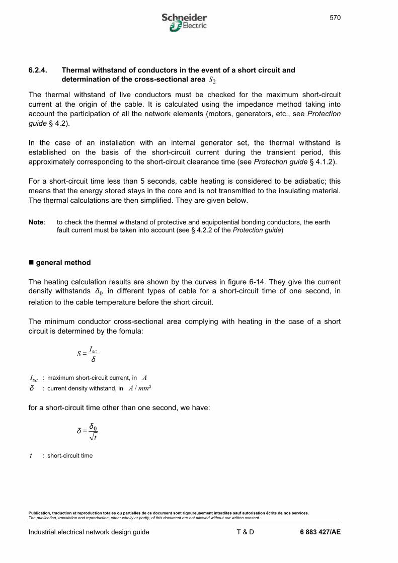
570
Publication, traduction et reproduction totales ou partielles de ce document sont rigoureusement interdites sauf autorisation écrite de nos services.
The publication, translation and reproduction, either wholly or partly, of this document are not allowed without our written consent.
Industrial electrical network design guide T & D 6 883 427/AE
6.2.4. Thermal withstand of conductors in the event of a short circuit and
determination of the cross-sectional area S2
The thermal withstand of live conductors must be checked for the maximum short-circuit
current at the origin of the cable. It is calculated using the impedance method taking into
account the participation of all the network elements (motors, generators, etc., see Protection
guide § 4.2).
In the case of an installation with an internal generator set, the thermal withstand is
established on the basis of the short-circuit current during the transient period, this
approximately corresponding to the short-circuit clearance time (see Protection guide § 4.1.2).
For a short-circuit time less than 5 seconds, cable heating is considered to be adiabatic; this
means that the energy stored stays in the core and is not transmitted to the insulating material.
The thermal calculations are then simplified. They are given below.
Note: to check the thermal withstand of protective and equipotential bonding conductors, the earthfault current must be taken into account (see § 4.2.2 of the Protection guide)
n general method
The heating calculation results are shown by the curves in figure 6-14. They give the current
density withstands δ 0 in different types of cable for a short-circuit time of one second, in
relation to the cable temperature before the short circuit.
The minimum conductor cross-sectional area complying with heating in the case of a short
circuit is determined by the fomula:
SIsc=δ
Isc : maximum short-circuit current, in A
δ : current density withstand, in A mm/ ²
for a short-circuit time other than one second, we have:
δ δ= 0
t
t : short-circuit time
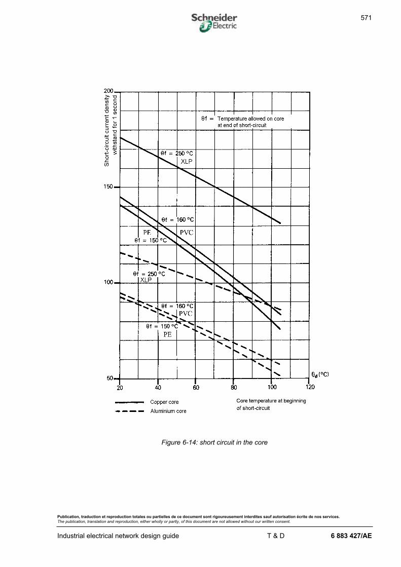
571
Publication, traduction et reproduction totales ou partielles de ce document sont rigoureusement interdites sauf autorisation écrite de nos services.
The publication, translation and reproduction, either wholly or partly, of this document are not allowed without our written consent.
Industrial electrical network design guide T & D 6 883 427/AE
Figure 6-14: short circuit in the core

572
Publication, traduction et reproduction totales ou partielles de ce document sont rigoureusement interdites sauf autorisation écrite de nos services.
The publication, translation and reproduction, either wholly or partly, of this document are not allowed without our written consent.
Industrial electrical network design guide T & D 6 883 427/AE
n simplified method
This assumes that the cable temperature before the short circuit is equal to the temperature
allowed in steady-state operating conditions.
In this case, the conductor cross-sectional area must meet the following condition:
SI
ktsc≥
Isc : maximum short-circuit current
t : short-circuit time
k : coefficient the value of which is given in table 6-35
For protective conductors, the current to be taken into account is the earth fault current I f .
Insulating material
PVC
PE
XLPE
EPR
Live conductors
- in copper 115 143
- in aluminium 74 94
Protective conductors a b a b
- in copper 143 115 176 143
- in aluminium 95 75 116 94
- in steel 52 _ 64 _
a protective conductors not incorporated in cables
b protective conductors incorporated in cables
Table 6-35: coefficient k values
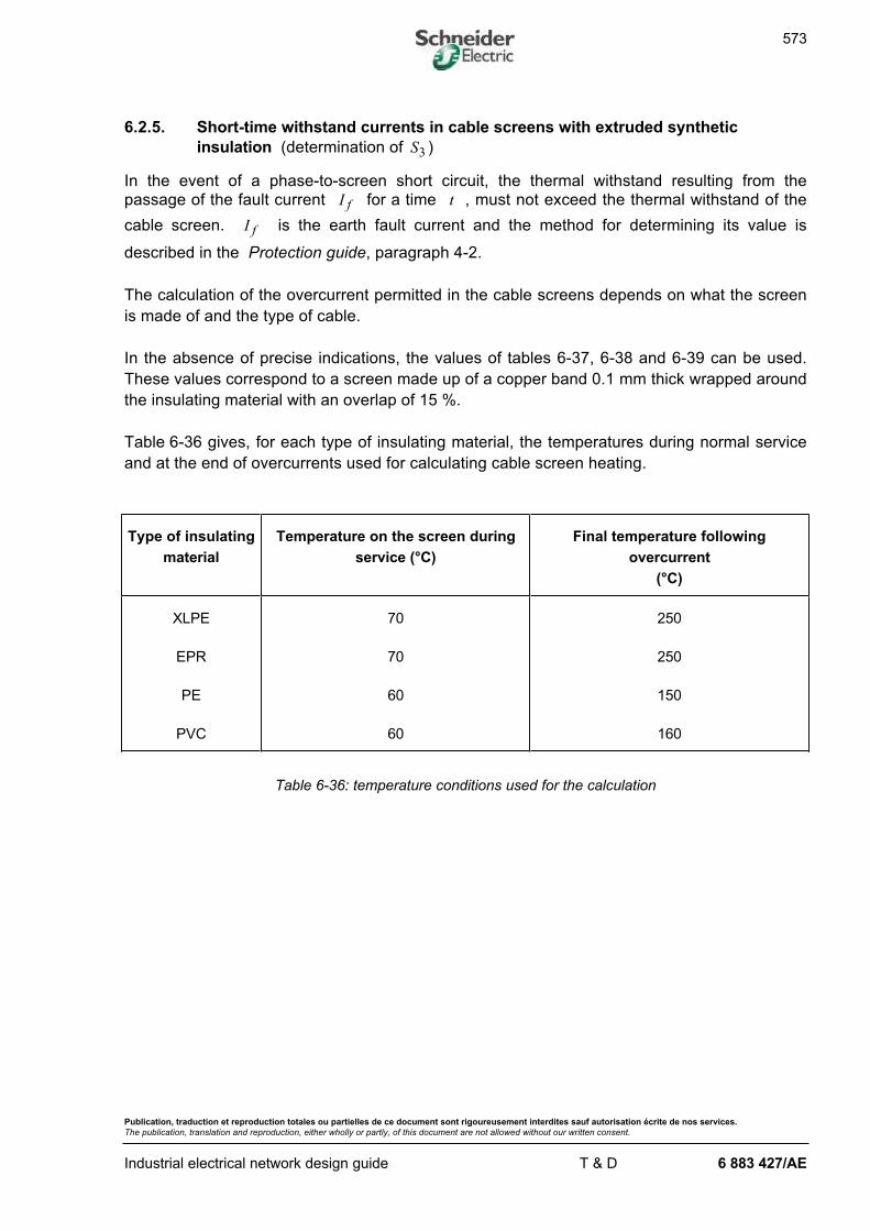
573
Publication, traduction et reproduction totales ou partielles de ce document sont rigoureusement interdites sauf autorisation écrite de nos services.
The publication, translation and reproduction, either wholly or partly, of this document are not allowed without our written consent.
Industrial electrical network design guide T & D 6 883 427/AE
6.2.5. Short-time withstand currents in cable screens with extruded synthetic
insulation (determination of S3 )
In the event of a phase-to-screen short circuit, the thermal withstand resulting from the
passage of the fault current I f for a time t , must not exceed the thermal withstand of the
cable screen. I f is the earth fault current and the method for determining its value is
described in the Protection guide, paragraph 4-2.
The calculation of the overcurrent permitted in the cable screens depends on what the screen
is made of and the type of cable.
In the absence of precise indications, the values of tables 6-37, 6-38 and 6-39 can be used.
These values correspond to a screen made up of a copper band 0.1 mm thick wrapped around
the insulating material with an overlap of 15 %.
Table 6-36 gives, for each type of insulating material, the temperatures during normal service
and at the end of overcurrents used for calculating cable screen heating.
Type of insulating
material
Temperature on the screen during
service (°C)
Final temperature following
overcurrent
(°C)
XLPE
EPR
PE
PVC
70
70
60
60
250
250
150
160
Table 6-36: temperature conditions used for the calculation
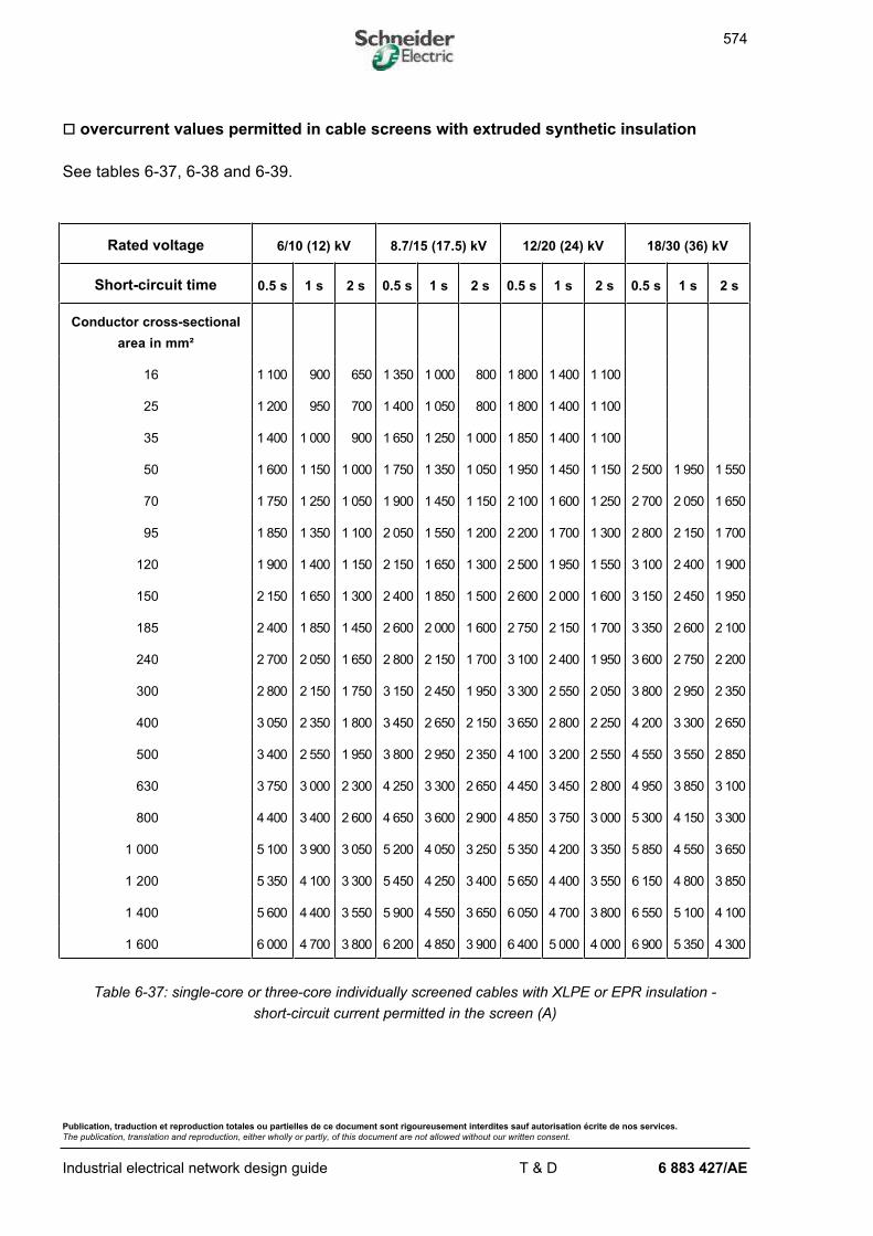
574
Publication, traduction et reproduction totales ou partielles de ce document sont rigoureusement interdites sauf autorisation écrite de nos services.
The publication, translation and reproduction, either wholly or partly, of this document are not allowed without our written consent.
Industrial electrical network design guide T & D 6 883 427/AE
o overcurrent values permitted in cable screens with extruded synthetic insulation
See tables 6-37, 6-38 and 6-39.
Rated voltage 6/10 (12) kV 8.7/15 (17.5) kV 12/20 (24) kV 18/30 (36) kV
Short-circuit time 0.5 s 1 s 2 s 0.5 s 1 s 2 s 0.5 s 1 s 2 s 0.5 s 1 s 2 s
Conductor cross-sectional
area in mm²
16 1 100 900 650 1 350 1 000 800 1 800 1 400 1 100
25 1 200 950 700 1 400 1 050 800 1 800 1 400 1 100
35 1 400 1 000 900 1 650 1 250 1 000 1 850 1 400 1 100
50 1 600 1 150 1 000 1 750 1 350 1 050 1 950 1 450 1 150 2 500 1 950 1 550
70 1 750 1 250 1 050 1 900 1 450 1 150 2 100 1 600 1 250 2 700 2 050 1 650
95 1 850 1 350 1 100 2 050 1 550 1 200 2 200 1 700 1 300 2 800 2 150 1 700
120 1 900 1 400 1 150 2 150 1 650 1 300 2 500 1 950 1 550 3 100 2 400 1 900
150 2 150 1 650 1 300 2 400 1 850 1 500 2 600 2 000 1 600 3 150 2 450 1 950
185 2 400 1 850 1 450 2 600 2 000 1 600 2 750 2 150 1 700 3 350 2 600 2 100
240 2 700 2 050 1 650 2 800 2 150 1 700 3 100 2 400 1 950 3 600 2 750 2 200
300 2 800 2 150 1 750 3 150 2 450 1 950 3 300 2 550 2 050 3 800 2 950 2 350
400 3 050 2 350 1 800 3 450 2 650 2 150 3 650 2 800 2 250 4 200 3 300 2 650
500 3 400 2 550 1 950 3 800 2 950 2 350 4 100 3 200 2 550 4 550 3 550 2 850
630 3 750 3 000 2 300 4 250 3 300 2 650 4 450 3 450 2 800 4 950 3 850 3 100
800 4 400 3 400 2 600 4 650 3 600 2 900 4 850 3 750 3 000 5 300 4 150 3 300
1 000 5 100 3 900 3 050 5 200 4 050 3 250 5 350 4 200 3 350 5 850 4 550 3 650
1 200 5 350 4 100 3 300 5 450 4 250 3 400 5 650 4 400 3 550 6 150 4 800 3 850
1 400 5 600 4 400 3 550 5 900 4 550 3 650 6 050 4 700 3 800 6 550 5 100 4 100
1 600 6 000 4 700 3 800 6 200 4 850 3 900 6 400 5 000 4 000 6 900 5 350 4 300
Table 6-37: single-core or three-core individually screened cables with XLPE or EPR insulation -
short-circuit current permitted in the screen (A)
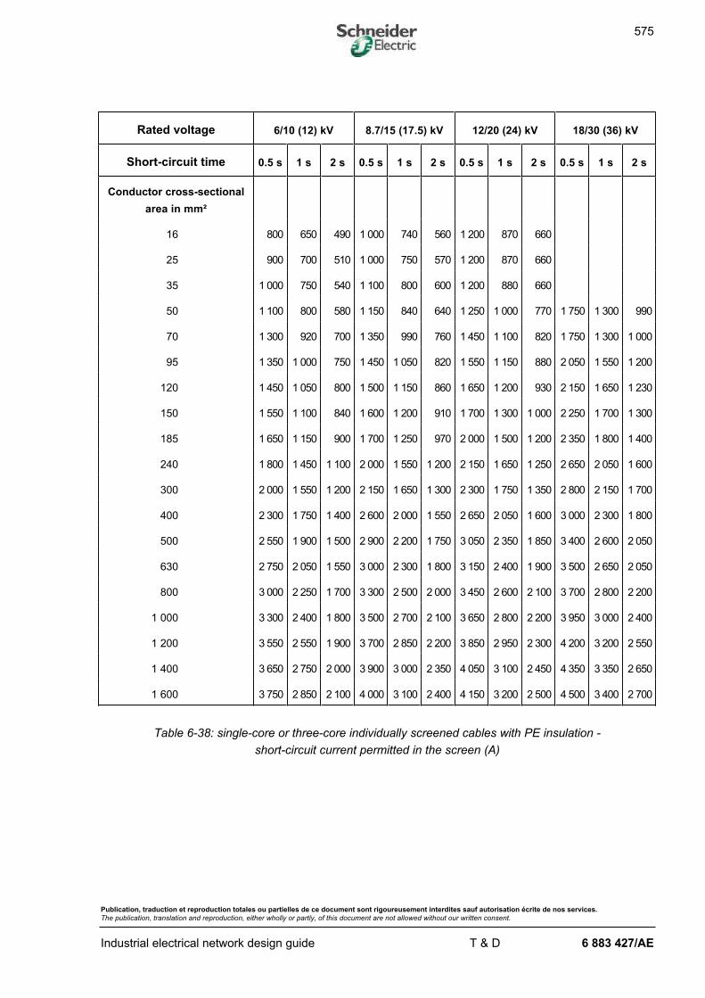
575
Publication, traduction et reproduction totales ou partielles de ce document sont rigoureusement interdites sauf autorisation écrite de nos services.
The publication, translation and reproduction, either wholly or partly, of this document are not allowed without our written consent.
Industrial electrical network design guide T & D 6 883 427/AE
Rated voltage 6/10 (12) kV 8.7/15 (17.5) kV 12/20 (24) kV 18/30 (36) kV
Short-circuit time 0.5 s 1 s 2 s 0.5 s 1 s 2 s 0.5 s 1 s 2 s 0.5 s 1 s 2 s
Conductor cross-sectional
area in mm²
16 800 650 490 1 000 740 560 1 200 870 660
25 900 700 510 1 000 750 570 1 200 870 660
35 1 000 750 540 1 100 800 600 1 200 880 660
50 1 100 800 580 1 150 840 640 1 250 1 000 770 1 750 1 300 990
70 1 300 920 700 1 350 990 760 1 450 1 100 820 1 750 1 300 1 000
95 1 350 1 000 750 1 450 1 050 820 1 550 1 150 880 2 050 1 550 1 200
120 1 450 1 050 800 1 500 1 150 860 1 650 1 200 930 2 150 1 650 1 230
150 1 550 1 100 840 1 600 1 200 910 1 700 1 300 1 000 2 250 1 700 1 300
185 1 650 1 150 900 1 700 1 250 970 2 000 1 500 1 200 2 350 1 800 1 400
240 1 800 1 450 1 100 2 000 1 550 1 200 2 150 1 650 1 250 2 650 2 050 1 600
300 2 000 1 550 1 200 2 150 1 650 1 300 2 300 1 750 1 350 2 800 2 150 1 700
400 2 300 1 750 1 400 2 600 2 000 1 550 2 650 2 050 1 600 3 000 2 300 1 800
500 2 550 1 900 1 500 2 900 2 200 1 750 3 050 2 350 1 850 3 400 2 600 2 050
630 2 750 2 050 1 550 3 000 2 300 1 800 3 150 2 400 1 900 3 500 2 650 2 050
800 3 000 2 250 1 700 3 300 2 500 2 000 3 450 2 600 2 100 3 700 2 800 2 200
1 000 3 300 2 400 1 800 3 500 2 700 2 100 3 650 2 800 2 200 3 950 3 000 2 400
1 200 3 550 2 550 1 900 3 700 2 850 2 200 3 850 2 950 2 300 4 200 3 200 2 550
1 400 3 650 2 750 2 000 3 900 3 000 2 350 4 050 3 100 2 450 4 350 3 350 2 650
1 600 3 750 2 850 2 100 4 000 3 100 2 400 4 150 3 200 2 500 4 500 3 400 2 700
Table 6-38: single-core or three-core individually screened cables with PE insulation -
short-circuit current permitted in the screen (A)
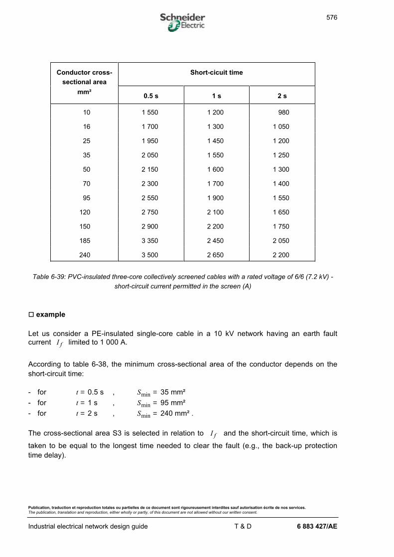
576
Publication, traduction et reproduction totales ou partielles de ce document sont rigoureusement interdites sauf autorisation écrite de nos services.
The publication, translation and reproduction, either wholly or partly, of this document are not allowed without our written consent.
Industrial electrical network design guide T & D 6 883 427/AE
Conductor cross-
sectional area
Short-cicuit time
mm²0.5 s 1 s 2 s
10 1 550 1 200 980
16 1 700 1 300 1 050
25 1 950 1 450 1 200
35 2 050 1 550 1 250
50 2 150 1 600 1 300
70 2 300 1 700 1 400
95 2 550 1 900 1 550
120 2 750 2 100 1 650
150 2 900 2 200 1 750
185 3 350 2 450 2 050
240 3 500 2 650 2 200
Table 6-39: PVC-insulated three-core collectively screened cables with a rated voltage of 6/6 (7.2 kV) -
short-circuit current permitted in the screen (A)
o example
Let us consider a PE-insulated single-core cable in a 10 kV network having an earth fault
current I f limited to 1 000 A.
According to table 6-38, the minimum cross-sectional area of the conductor depends on the
short-circuit time:
- for t = 0.5 s , Smin = 35 mm²
- for t = 1 s , Smin = 95 mm²
- for t = 2 s , Smin = 240 mm² .
The cross-sectional area S3 is selected in relation to I f and the short-circuit time, which is
taken to be equal to the longest time needed to clear the fault (e.g., the back-up protection
time delay).
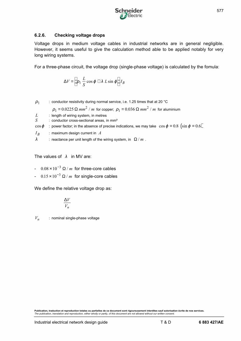
577
Publication, traduction et reproduction totales ou partielles de ce document sont rigoureusement interdites sauf autorisation écrite de nos services.
The publication, translation and reproduction, either wholly or partly, of this document are not allowed without our written consent.
Industrial electrical network design guide T & D 6 883 427/AE
6.2.6. Checking voltage drops
Voltage drops in medium voltage cables in industrial networks are in general negligible.
However, it seems useful to give the calculation method able to be applied notably for very
long wiring systems.
For a three-phase circuit, the voltage drop (single-phase voltage) is calculated by the fomula:
∆VL
SL IB= +
ρ ϕ λ ϕ1 cos sin
ρ1 : conductor resistivity during normal service, i.e. 1.25 times that at 20 °C
ρ120 0225= . /Ω mm m for copper; ρ1
20 036= . /Ω mm m for aluminium
L : length of wiring system, in metres
S : conductor cross-sectional areas, in mm²
cosϕ : power factor; in the absence of precise indications, we may take ( )cos . sin .ϕ ϕ= =0 8 0 6
IB : maximum design current in A
λ : reactance per unit length of the wiring system, in Ω /m .
The values of λ in MV are:
- 0 08 10 3. /× − Ω m for three-core cables
- 0 15 10 3. /× − Ω m for single-core cables
We define the relative voltage drop as:
∆V
Vn
Vn : nominal single-phase voltage
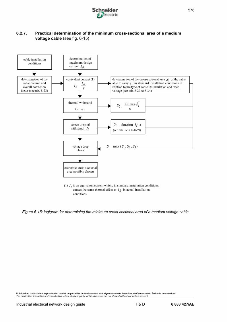
578
Publication, traduction et reproduction totales ou partielles de ce document sont rigoureusement interdites sauf autorisation écrite de nos services.
The publication, translation and reproduction, either wholly or partly, of this document are not allowed without our written consent.
Industrial electrical network design guide T & D 6 883 427/AE
6.2.7. Practical determination of the minimum cross-sectional area of a medium
voltage cable (see fig. 6-15)
determination of
maximum design
current
equivalent current (1)
thermal withstand
screen thermal
withstand:
voltage drop
check
determination of the cross-sectional area of the cable
able to carry in standard installation conditions in
relation to the type of cable, its insulation and rated
voltage (see tab. 8-29 to 8-34)
determination of the
cable column and
overall correction
factor (see tab. 8-23)
IB
S S S Smax ( , , )1 2 3
cable installation
conditions
Iz
S1
economic cross-sectional
area possibly chosen
(1) is an equivalent current which, in standard installation conditions,
causes the same thermal effect as in actual installation
conditions
IzIB
II
fz
B
Iscmax
(see tab. 8-37 to 8-39)
S I tf3 ,functionIf
SI
ktsc
2max
Figure 6-15: logigram for determining the minimum cross-sectional area of a medium voltage cable
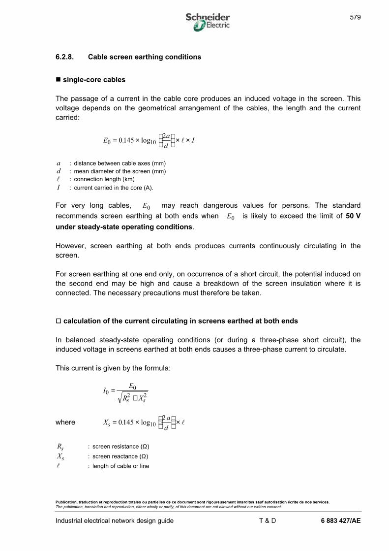
579
Publication, traduction et reproduction totales ou partielles de ce document sont rigoureusement interdites sauf autorisation écrite de nos services.
The publication, translation and reproduction, either wholly or partly, of this document are not allowed without our written consent.
Industrial electrical network design guide T & D 6 883 427/AE
6.2.8. Cable screen earthing conditions
n single-core cables
The passage of a current in the cable core produces an induced voltage in the screen. This
voltage depends on the geometrical arrangement of the cables, the length and the current
carried:
Ea
dI0 100145
2= ×
× ×. log l
a : distance between cable axes (mm)
d : mean diameter of the screen (mm)
l : connection length (km)
I : current carried in the core (A).
For very long cables, E0 may reach dangerous values for persons. The standard
recommends screen earthing at both ends when E0 is likely to exceed the limit of 50 V
under steady-state operating conditions.
However, screen earthing at both ends produces currents continuously circulating in the
screen.
For screen earthing at one end only, on occurrence of a short circuit, the potential induced on
the second end may be high and cause a breakdown of the screen insulation where it is
connected. The necessary precautions must therefore be taken.
o calculation of the current circulating in screens earthed at both ends
In balanced steady-state operating conditions (or during a three-phase short circuit), the
induced voltage in screens earthed at both ends causes a three-phase current to circulate.
This current is given by the formula:
IE
R Xs s
00
2 2=
+
where Xa
ds = ×
×0145
210. log l
Rs : screen resistance (Ω)
Xs : screen reactance (Ω)
l : length of cable or line
580
Publication, traduction et reproduction totales ou partielles de ce document sont rigoureusement interdites sauf autorisation écrite de nos services.
The publication, translation and reproduction, either wholly or partly, of this document are not allowed without our written consent.
Industrial electrical network design guide T & D 6 883 427/AE
o example
Let us consider a 20 kV aluminium single-core cable with a cross-sectional area of 300 mm² ,
with PE insulation and a length of l = 3 km , buried in soil having a resistivity of ρ = ⋅100Ω m ,
the characteristics of which are as follows:
- I Acapacity = 500- d mm= 33 5.- a mm= 38 5.- R kms = 0.45 /Ω
It is installed in a network such that:
- I AB = 400- I kAsc = 8
The induced voltage under steady-state operating conditions is:
Ea
dI VB0 100145
263= ×
× × =. log l
The 50 V limit is exceeded and the screen must therefore be earthed at both ends.
The circulation current in the screen is in this case:
IE
R Xs s
00
2 2=
+
Rs = 1.35 Ω
Xs = 0 1452
015710. log .×
× =a
dl Ω
whence I A0 46= .4
Note: the circulation current in the screen is independent of the cable length.
581
Publication, traduction et reproduction totales ou partielles de ce document sont rigoureusement interdites sauf autorisation écrite de nos services.
The publication, translation and reproduction, either wholly or partly, of this document are not allowed without our written consent.
Industrial electrical network design guide T & D 6 883 427/AE
The induced voltage in the event of a short circuit is:
Ea
dI Vsc sc0 100145
21260= ×
× × =. log l
The circulation current in the screen is then:
I Asc0 927=
This current must be withstood by the screen for the maximum short-circuit time. This is the
case since it can withstand 1 350 A for 2 s (see table 6-38).
Note: if the cable length was 2 km, the screen would be earthed at one end only. The voltage inducedin the screen on occurrence of the short circuit will then be equal to 840 V. In this case it isnecessary to check that the screen insulation at the point where the terminal box is located issufficient.
Evaluation of Ws losses in the screen
W R Is s= 02
for R kms = 0.45 /Ω , l = 3 km and I A0 46= .4
( )W kWs = × × =0 3 46 2 92
.45 .4 .
The losses in the core are:
W R Ic c B= × 2
Rc : core resistance
For an aluminium conductor with a cross-sectional area of S mm= 300 ² , R kmc = 01. /Ω
whence ( )W kWc = × × =0 1 3 400 482
.
We determine the ratioW
W
s
c
= 6%
The screen losses represent 6 % of the core losses. They must therefore be taken into
account when determining the maximum current-carrying capacity of the cable.
582
Publication, traduction et reproduction totales ou partielles de ce document sont rigoureusement interdites sauf autorisation écrite de nos services.
The publication, translation and reproduction, either wholly or partly, of this document are not allowed without our written consent.
Industrial electrical network design guide T & D 6 883 427/AE
o thermal effect in the cable screens
As we saw in the previous example, when the screen is earthed at both ends, the continuous
circulation of induced current in the screen causes extra heating in the cable and consequently
reduces its current-carrying capacity.
Generally, this phenomenon is only to be taken into account for cables with a cross-sectional
area greater than 240 mm².
We can apply the following rule:
- thin screen without armour, for S mm>1000 ² the current-carrying capacity is reduced by 5 %
- non-thin screen without armour, the current-carrying capacity is to be reduced by:
. 5 % for 240 800mm S mm² ²≤ ≤
. 10 % for S mm> 800 ²
- cables with screen and armour, the current-carrying capacity is to be reduced by:
. 5 % for 240 400mm S mm² ²≤ ≤
. 10 % for 500 800mm S mm² ²≤ ≤
. 15 % for S mm> 800 ²
n three-core cables
For three-core collectively screened cables, the electromagnetic field is zero in balanced
operating conditions.
In normal operating conditions, there is no circulation current in the screen.
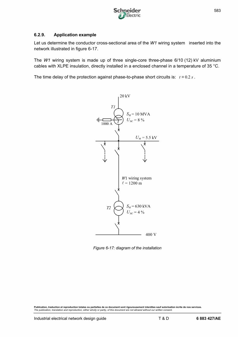
583
Publication, traduction et reproduction totales ou partielles de ce document sont rigoureusement interdites sauf autorisation écrite de nos services.
The publication, translation and reproduction, either wholly or partly, of this document are not allowed without our written consent.
Industrial electrical network design guide T & D 6 883 427/AE
6.2.9. Application example
Let us determine the conductor cross-sectional area of the W1 wiring system inserted into the
network illustrated in figure 6-17.
The W1 wiring system is made up of three single-core three-phase 6/10 (12) kV aluminium
cables with XLPE insulation, directly installed in a enclosed channel in a temperature of 35 °C.
The time delay of the protection against phase-to-phase short circuits is: t s= 0 2. .
400 V
wiring system
= 1200 ml
= 630 kVASnT2
T1
= 10 MVASn
= 8 %
20 kV
1000 AUsc
W1
= 4 %Usc
Un = 5.5 kV
Figure 6-17: diagram of the installation
584
Publication, traduction et reproduction totales ou partielles de ce document sont rigoureusement interdites sauf autorisation écrite de nos services.
The publication, translation and reproduction, either wholly or partly, of this document are not allowed without our written consent.
Industrial electrical network design guide T & D 6 883 427/AE
n determining the maximum design current IB
The W1 wiring system only feeds the 630 kVA power transformer T2 .
The current IB is thus taken to be equal to the nominal transformer current:
I IS
UAB n
n
n
= = = ×× ×
=3
630 10
3 5 5 1066
3
3.
n correction factors and choice of S1
The direct installation in an enclosed channel corresponds to installation type L4 (see
table 6-23). Column (3) in the current-carrying capacity tables must be used.
The correction factors to be applied are:
- installation method: f0 0 8= .
- ambient temperature (see table 6-24): f1 0 96= .
- group of several cables (see table 6-28): f5 1=
The overall correction factor is: f = × =0 8 0 96 0 77. . .
The equivalent current that the cable must be able to carry in standard installation conditions
is:
II
fAz
B= = 86
Table 6-31 (column (3), XLPE, aluminium) gives a minimum cross-sectional area of
S mm1216= which has a current-carrying capacity of I A0 95= .
585
Publication, traduction et reproduction totales ou partielles de ce document sont rigoureusement interdites sauf autorisation écrite de nos services.
The publication, translation and reproduction, either wholly or partly, of this document are not allowed without our written consent.
Industrial electrical network design guide T & D 6 883 427/AE
n checking thermal withstand ( )S2
Neglecting the impedance upstream of the transformer and the impedance of the transformer-
busbar connection, the maximum short-circuit current at the origin of the cable is equal to the
short-circuit current of the transformer.
The impedance of the transformer T1 is:
( )Z
U
S
UT
n
n
sc1
2 3 2
6100
5 5 10
10 10
8
1000 242= × =
×
×× =
.. Ω
The maximum short-circuit current is thus:
IU
ZkAsc
n
T
= = ××
×=11
311
5 5 10
3 0 24214
1
3
. ..
..4 (see Protection guide § 4.2.1)
The cross-sectional area complying with the short-circuit requirement is:
SI
ktsc
2 ≥
k = 94 : value of the coefficient corresponding to a XLPE-insulated aluminium conductor (see table 6-35)
t s= 0 2. : short-circuit time equal to the protection time delay
whence S mm2269≥
The minimum cross-sectional area to be chosen is thus S mm2270=
586
Publication, traduction et reproduction totales ou partielles de ce document sont rigoureusement interdites sauf autorisation écrite de nos services.
The publication, translation and reproduction, either wholly or partly, of this document are not allowed without our written consent.
Industrial electrical network design guide T & D 6 883 427/AE
n checking the cable screen thermal withstand ( )S3
The 5.5 kV distribution network has an earthing system with a 1 000 A current limiting resistor.
The fault current is then:
IV
RIf
n
NC= + (see Protection guide § 4.3.2)
Vn : single-phase network voltage
RN : limiting resistance
IC : 5.5 kV network capacitive current ( )I jC VC n= 3 ω
The capacitive current of an industrial network is of the order of several amps to several dozen
amps and it can thus be neglected in relation to the 1 000 A limiting current.
We thus have I f = 1 000 A
We assume that the screen must be able to withstand the fault current for 2 seconds, in order
to take into account the maximum time delay of the protection against phase-earth faults and
eventual reclosing.
The cross-sectional area of the conductor complying with the thermal withstand of the cable
screen is then:
S mm3250= (see table 6-37)
587
Publication, traduction et reproduction totales ou partielles de ce document sont rigoureusement interdites sauf autorisation écrite de nos services.
The publication, translation and reproduction, either wholly or partly, of this document are not allowed without our written consent.
Industrial electrical network design guide T & D 6 883 427/AE
n checking voltage drops
The voltage drop is given by the formula:
∆VS
IB= +
ρ ϕ λ ϕ1l
lcos sin
l =1200m ; S mm= 70 ² ; λ = × −015 10 3. /Ω m ; I AB = 66 ; ρ120 036= ⋅. /Ω mm m
We assume that the cable load has a ( )cos . sin .ϕ ϕ= =0 6 0 8
whence ∆V = × + × × ×
×−
0 0361200
500 8 015 10 1200 0 6 66
3. . . .
∆V V= 53
The relative voltage drop is: ∆V
Vn
=
=53
1755003
. %
In spite of a very long cable length for an industrial network, the voltage drop is acceptable.
n choosing the technical cross-sectional area
The calculations carried out give the following cross-sectional areas:
S mm1 16= ²
S mm2 70= ²
S mm3 50= ²
The technical cross-sectional area to be chosen is thus:
S mm= 70 ²
588
Publication, traduction et reproduction totales ou partielles de ce document sont rigoureusement interdites sauf autorisation écrite de nos services.
The publication, translation and reproduction, either wholly or partly, of this document are not allowed without our written consent.
Industrial electrical network design guide T & D 6 883 427/AE
6.3. Calculating the economic cross-sectional area
The methods described in chapters 6-1 and 6-2 lead to the choice of technical cross-sectional
areas of wiring systems, complying with the different thermal withstands, voltage drops and
protection of persons.
But it may be useful to take into account the economic criterion, based on the cost of
investment and the operating costs, when looking for the optimum cross-sectional area.
The investment cost is essentially composed of:
- the cable cost, linear function of the cross-sectional area S and length L ,
i.e. K L K L S1 2+
- the cost of civil engineering and installation, depending on the length and regardless of the
cross-sectional area in a limited interval, i.e. K L3 .
The operating costs comprise:
- the Joule losses in the cable
- the maintenance costs.
To calculate the economic cross-sectional area, only the cost of the Joule losses w relative to
the wiring system is taken into account:
w nL
SIH C= × ×ρ 2
1 000 Euros.
n : number of live conductorsρ : resistivity of the live conductor during normal service, i.e. 1.25 times that at 20 °C.
ρ = 0 0225. ²/Ω mm m for copper; ρ = ×0 036, ² /Ω mm m for aluminium
L : cable length
S : cross-sectional area of conductors
I : current carried, assumed to be constant, in A
H : number of cable operating hours (for a year H = 8 760)
C : cost of kWh, Euro/kWh.
The cost of investment and the cost of losses w do not have the same term of payment. It is
necessary to change in order to carry out the sum of their values. This can be done by
converting the operating costs paid at the end of consecutive years to current value, i.e. by
converting them to the period in which the cable is purchased.
589
Publication, traduction et reproduction totales ou partielles de ce document sont rigoureusement interdites sauf autorisation écrite de nos services.
The publication, translation and reproduction, either wholly or partly, of this document are not allowed without our written consent.
Industrial electrical network design guide T & D 6 883 427/AE
If N (years) is the amortizement time forecast for the cable, and if the price of energy and
the cable load are assumed to be constant for the entire period, the sum of converted values
of Joule losses is:
( ) ( )( )
( )W w
t t t
wt
t tN
N
N=
++
++ +
+
= ×+ −
+
1
1
1
1
1
1
1 1
12
.......
t being the forecast conversion to current value rate.
We can write Ww
A= , where
( )( )
At t
t
N
N=
+
+ −
1
1 1
The total cost is therefore:
( )P S K L K L K L S nL
SI
H C
A= + + +
×3 1 22
1000ρ
The function ( )P S goes via a minimum∂∂P
S=
0
for a cross-sectional area of S In H C
K A0
2 1000=
×ρ
For an approximate calculation we can use the following formula:
SK I H C
Amm0
100= , ²
where K = 2 56. for copper and 4 61. for aluminium.
The value of the economic cross-sectional area to be chosen is the closest standard
value to S0 .
590
Publication, traduction et reproduction totales ou partielles de ce document sont rigoureusement interdites sauf autorisation écrite de nos services.
The publication, translation and reproduction, either wholly or partly, of this document are not allowed without our written consent.
Industrial electrical network design guide T & D 6 883 427/AE
n example
Taking the elements from the application example of § 6.2.9:
- design current I AB = 66
- energy cost: C Euro kWh= 0 061. /
- aluminium conductor, K = 4 61.
- conversion to current value rate of 8 %
- amortizement time N = 20 years
- number of operating hours H = 3 800 hours.
( )( )
A =× +
+ −=
0 08 1 0 08
1 0 08 10102
20
20
. .
..
S mm0
66 4 61
100
3 800 0 061
0102145= × × =. .
.²
The economic cross-sectional area is the closest standard value to S0 , i.e. S mm= 150 2 .
In practice, the economic cross-sectional area is often greater than the technical cross-
sectional area.
n advantages of cable oversizing
- Improved voltage quality under normal operating conditions and reduced amplitude of
voltage surges during motor or other machine starting.
- Presence of reserve power offering the possibility of future extensions.


![Cross sectional study.pptx [Read-Only]...Descriptive cross-sectional study Analytic cross-sectional study Repeated cross-sectional study 7 Descriptive Collected number of cases and](https://img.pdfslide.us/doc/110x75/5f0c07f77e708231d43368fd/cross-sectional-studypptx-read-only-descriptive-cross-sectional-study-analytic.jpg)