Embed Size (px)
Citation preview

“THE ORIGINATOR” OF MODERN CLINKER COOLER DESIGNS: PAST, PRESENT AND FUTURE DEVELOPMENTS
By:
IEEE-IAS Cement Industry Committee
Bo Bentsen, General Manager, Pyroprocessing Technology, FLSmidth A/S
Mads Jespersen, Manager, Cooler Systems, FLSmidth A/S Brian P. Keefe, Vice President, Engineering, FLSmidth Inc.
Robert E. Shenk, General Manager, Customer Service Projects, FLSmidth Inc. ABSTRACT In 1997, arguably the most revolutionary development witnessed by the cement industry in the last fifteen years took place when the first 3rd generation clinker coolers were put into operation. These 3rd generation coolers were characterized by the following innovative features: stationary grate line, separation of the conveying and cooling mechanisms, modular design, and active airflow control to every grate. These breakthrough technologies have subsequently led to the current clinker cooler innovations that are sweeping the industry. This paper will focus upon how this “Originator” of modern clinker cooler designs has evolved over the last eight (8) years to provide high reliability, low maintenance costs, and excellent process efficiency. Importantly, this paper will also demonstrate that the Originator technologies have recently become more affordable because they can now be easily retrofitted into any cooler on the market, resulting in significantly lower installation costs. INTRODUCTION The needs of the cement producer to sustain development and to continually improve bottom line results are the reasons why equipment manufacturers seek to improve existing equipment designs and spend millions of dollars on new designs. The clinker cooler is a critical component in the cement manufacturing process and has been an area of great innovation over the years because it represents the greatest potential for further improving the heat consumption of today’s modern kiln systems. The conventional (1st generation) grate cooler was developed in 1938 and it quickly became the predominate choice for the cement industry (compared to planetary and rotary coolers). A revolutionary development took place in the mid to late 1980s when the conventional grate cooler was further improved via air beams and high resistance grate plates. Substantial fuel savings were realized by the so called “airbeam” coolers; however, such 2nd generation designs did not come without added complexity and costs. Seizing an opportunity for improvement, a leading equipment supplier designed and implemented a breakthrough cooler technology in 1997, characterized by the following innovations:
• Stationary Grate Line for the Entire Cooler • Separation of Conveying and Cooling Functions • Flow Regulation to Every Grate Plate • Modular Design
0-7803-9107-1/05/$20.00 (c)2005 IEEE

FIGURE 1: Stationary Grate Line FIGURE 2: Separation of Conveying and Cooling Mechanism
FIGURE 3: Modular Design FIGURE 4: Active Airflow Regulation
Each of these innovative features has been detailed in prior publications and as such will not be discussed in this paper. However, the key benefits of this technology can be summarized as follows:
• Significantly Improved Reliability • Reduced Maintenance Costs • Predictable Maintenance • Commonality of Spare Parts • High and Constant Thermal Efficiency Over Time • Quick and Easy Installations • Workshop Quality
Due to the separation of cooling and conveying functions, the technology became a win-win solution for both the plant process engineer and maintenance manager. Modular design reduced installation times and the ‘split-drive’ configuration enabled both flexible operation and extremely high availability. With the 3rd generation designs, down-time caused by the clinker cooler generally became a thing of the past. With the successful implementation of these new technologies, competitors began to develop new designs over recent years; however, these “new” designs largely draw upon the success of the original, innovative features first developed in 1997. As such, the original breakthrough cooler design shall, henceforth, be referred to as the “Originator” of modern clinker cooler designs.
0-7803-9107-1/05/$20.00 (c)2005 IEEE

RESULTS Rather than to discuss the theory behind the Originator and to discuss how it meets the previously mentioned benefits, it is better to provide case studies from actual coolers in operation: Reliability In late 1996, a cement producer in Pennsylvania was looking at the need to spend well over half a million dollars just to maintain its existing traditional grate cooler during an upcoming outage. At this same time, the Originator was being developed and the equipment supplier approached the cement producer about becoming the first installation of the innovative (3rd generation) cooler design. The cement producer quickly realized all of the Originator’s benefits, including reliability which, as outlined in the following paragraph, became its most important benefit. Prior to the installation of the Originator in 1997, the average monthly kiln up time was 86.1% (inclusive of annual outages) for the two previous years of the cement producer’s operation. Conversely, upon installation of the Originator, the cement producer obtained an average monthly kiln up time of 90.8% (inclusive of annual outages) or 95.9% (exclusive of annual outages) over the next four years. The monthly reliability history can be seen in FIGURE 5 and FIGURE 6. Specific notation should be made to the increased number of months where 100% up time was achieved.
0.0
10.0
20.0
30.0
40.0
50.0
60.0
70.0
80.0
90.0
100.0
Kiln
Ope
ratin
g Pe
rcen
tage
(%)
Apr
-98
Jun-
98
Aug
-98
Oct
-98
Dec
-98
Feb-
99
Apr
-99
Jun-
99
Aug
-99
Oct
-99
Dec
-99
Feb-
00
Apr
-00
Jun-
00
Aug
-00
Oct
-00
Dec
-00
Feb-
01
Apr
-01
Jun-
01
Aug
-01
Oct
-01
Dec
-01
Time
FIGURE 6: Kiln Up Time with Originator Cooler
0.0
10.0
20.0
30.0
40.0
50.0
60.0
70.0
80.0
90.0
100.0
Kiln
Ope
ratin
g Pe
rcen
tage
(%)
Jan-
96
Feb-
96
Mar
-96
Apr
-96
May
-96
Jun-
96
Jul-9
6
Aug-
96
Sep-
96
Oct
-96
Nov
-96
Dec
-96
Jan-
97
Feb-
97
Mar
-97
Apr
-97
May
-97
Jun-
97
Jul-9
7
Aug-
97
Sep-
97
Oct
-97
Nov
-97
Dec
-97
Jan-
98
Feb-
98
Date
FIGURE 5: Kiln Up Time with Traditional Grate Cooler
0-7803-9107-1/05/$20.00 (c)2005 IEEE

Maintenance Costs As originally introduced, the Originator’s wear components were specifically targeted for a minimum of one full year of operation. As such, the wear part materials were initially tailored towards heat resistance. However, upon gaining operational experience with the first few coolers, it was quickly discovered that the wear component’s metallurgy could be completely tailored towards wear protection. With the advent of the new metallurgy, the longevity target became a minimum of two full years of operation. With experience gained from the first coolers, it was quickly determined how and when the wear parts (moveable bars, stationary bars, retainer blocks, drive seals, and grate protectors) would require changing based on the number of drive cycles per year. In this manner, the maintenance of the Originator became very predictable from year to year, which provided immeasurable benefits to cement producers in terms of maintenance planning. All of the wear components are standard designs; applicable to all coolers. As such, there is extensive commonality of wear parts and ease of access. When such wear parts eventually needed to be replaced, it was found this task could be completed without special training within a couple of shifts during any given annual outage and, therefore, never a critical path item for the cement producer. With the current optimized design of the Originator, the average annual parts price over a 10 year period is typically only 0.05 to 0.07 dollars per ton of clinker. The expected consumption over the first 10 years of lifetime is detailed in FIGURE 7. Of course, this figure may vary due to factors such as: cooler inclination, clinker particle size, bed depth, and airloading; lower costs have been appreciated in certain cases.
0
0.02
0.04
0.06
0.08
0.1
0.12
0.14
1 2 3 4 5 6 7 8 9 10
Years Operating
Mai
nten
ance
Cos
t (U
S$/M
T C
linke
r)
5 Year Average$0.056 / MT Clk
10 Year Average$0.066 / MT Clk
FIGURE 7: Average Annual Maintenance Costs Expected for Originator
0-7803-9107-1/05/$20.00 (c)2005 IEEE

Thermal Efficiency Time and time again, the high thermal efficiency of the Originator has been realized. Outstanding process efficiency has been realized not only during the initial performance test period, but it has been proven to remain highly efficient after many years of operation as a result of the separation between the cooling and conveying functions. FIGURE 8 details the performance over time of the Originator on a wet kiln installation in the USA, while FIGURE 9 details the performance test results of a recently commissioned calciner kiln system in Europe.
WET PROCESS KILN – USA Before (1997)
P-Test (1998)
Audit (2002)
Heat Consumption (kcal/kg) 1522 1284 1176
Cooling Air to Grate (NM3/kg) 2.63 1.47 1.75
Excess Air (NM3/kg) (Vent Air + Coal Mill) 1.45 0.36 0.52
Secondary Air (°C) 601 750 905
Clinker Temperature (°C) Above Ambient 86 80 44
Undergrate Fans (kWh/MT) 4.8 4.4 4.8
Cooler Loss (kcal/kg) 115 59 55
Standard Cooler Loss (kcal/kg) 155 80 85
FIGURE 8: Results Over Time for Originator in USA
CALCINER KILN SYSTEM (2003) Kg/kg cl NM3/kg
Clinker Production 3716 tpd
Heat Consumption 721 kcal/kg
Cooling Air 2.13 1.66
Excess Air 1.02 0.79
Secondary Air 1062°C
Tertiary Air 986°C
Clinker Temperature Above Ambient 65°C
Power Consumption 4.06 kWh/t
Cooler Loss, VDZ Definition 92.6 kcal/kg
Efficiency, Ref. Amb. VDZ Basis 75.60%
FIGURE 9: Recent Originator Results
0-7803-9107-1/05/$20.00 (c)2005 IEEE

Market Acceptance A short status update shows that more than 80 Originator coolers have been ordered to date, which is the best indicator of market acceptance. The Originator has been chosen for various projects: Greenfield and upgrading projects as well as single machine units - and by both independent cement manufacturers as well as international cement producers. The total installed capacity of such coolers exceeds 100 million tpy, with the resulting reduction in power consumption, flow optimization and savings in wear parts adding up to huge sums of money. MORE THAN JUST A GRATELINE In terms of equipment and market acceptance, the Originator is more than just a cooler. Besides the innovative conveying system the Originator incorporates a controlled impact system and normally a clinker crusher or a heavy duty roller breaker. Additional options are a water injection system or an air-to-air heat exchanger for the excess air system. A video camera can be installed enabling monitoring from the control room. These add-ons maintain the same high standards of efficiency and quality as the Originator itself and can also be ordered as stand-alone products for other cooler types. Controlled Impact Section – A Controlled Cooler Inlet The controlled impact system with flow regulation fitted at the cooler inlet consists of inclined, stationary grate plates, each with a flow regulator. The purpose of the inlet is to receive the clinker from the kiln, distribute it and quickly quench it as much as possible before the grate line. The controlled impact section fits into all Originator type coolers and is available for any size of retrofit installation, including traditional grate coolers.
FIGURE 10: A Retrofit Inlet FIGURE 11: Real Life Picture from an Originator Cooler in Operation
0-7803-9107-1/05/$20.00 (c)2005 IEEE

Installing a controlled impact section improves cooler operation and increases throughput. At the same time fuel and power consumption are lowered and maintenance costs are reduced since there are no moving grates at the inlet. Again, the performance of the inlet has been proven in cooler after cooler as fuel consumption may be guaranteed for typical installations (refer to FIGURE12 for several examples).
PLANT COOLER TYPE CAPACITY MTPD
GUARANTEED FUEL SAVINGS
ACTUAL FUEL SAVINGS
A Grate Cooler 4500 20 25.3 B Grate Cooler 1500 20 23.6 C Grate Cooler 4000 20 20-25 D Grate Cooler 2000 15 26.1 E Grate Cooler 2000 15 35.2 F Grate Cooler 2000 15 26.7 G Grate Cooler 4000 18 28.6 H Grate Cooler 750 25 39 I Air-Beam Cooler 4700 10 12.6 J Grate Cooler 3175 30 38 K Grate Cooler 2100 40 42.7 L Grate Cooler 2100 40 42 M Grate Cooler 6000 25 26.8 N Grate Cooler 1724 30 46.8 O Grate Cooler 1700 20 22 P Grate Cooler 1700 20 23.6 Q Air-Beam Cooler 6000 8 8 R Grate Cooler 6000 25 25
FIGURE 12: Controlled Impact Section Performance Results
When installing a controlled impact section, it is often possible to reuse one of the existing fans, since only one fan is needed, and the air load for this section is typically 100 kg air/m2/min @ 100 kPa. When retrofitting a controlled impact section into a traditional cooler, the inlet will be tailored to fit the first grate section, which is possible due to the simple and flexible construction of the controlled impact section. This inlet itself has also gradually been improved, and recently an innovative version that minimizes snowman formation has been introduced. This further increases cooler availability, since operations do not have to be stopped to remove snowmen. Including the above-mentioned 80 Originator coolers, all with controlled impact sections, a grand total of 125 controlled impact sections have been sold, handling a total production of approximately 150 million tpy.
0-7803-9107-1/05/$20.00 (c)2005 IEEE

Reliable Clinker Crusher for Any Size The clinker crusher fitted at the cooler outlet is a traditional crusher with hammers and fine separation by grizzly bars (FIGURE 13). It is simple to operate and very reliable in operation. The service life of the hammers, the shaft and other components plus the availability and maintenance requirements has been improved over the years. This type of clinker crusher will have capacities that match almost any size of cooler. Over the last 20 years, more than 230 units of varying design have been installed. These clinker crushers can also be delivered as a stand-alone unit with 42 having been sold since 2000. Versatile Heavy Duty Roller Breaker An alternative to the clinker crusher is the heavy duty roller breaker (HRB) installed at the cooler outlet. It has between three and five horizontal crusher shafts fitted with exchangeable crushing segments. The number of shafts matches a certain production range and the HRB’s come in capacities for all productions. The uniquely designed HRB, as shown on FIGURE 14, features two crushing rollers and a number of conveying rollers depending on the size. The first crushing roller in the clinker flow direction is placed lower than the other rollers. This “exclusive cavity feature” ensures a better grip of big clinker pieces or kiln coatings. The conveying rollers are adjustable in speed to optimise the throughput and durability. The basic function of the conveying rollers is to pass extremely large clinker pieces and kiln coating to the crushing shafts without interfering with the pyro process. The HRB offers many features and comes in two versions: hydraulic or electromechanically-driven. Both versions allow the drive to be placed on either side of the crusher depending on maintenance requirements or to accommodate other equipment.
FIGURE 14: Heavy Duty Roller Breaker
FIGURE 13: Clinker Crusher
0-7803-9107-1/05/$20.00 (c)2005 IEEE

A version of the HRB can also be installed as a mid-cooler breaker (FIGURE 15) in any cooler type. For example, in an Originator cooler four modules wide by six modules long, the breaker is positioned after the first four modules with two modules after it. The obvious benefits of doing so are more consistent clinker granulometry after the HRB which improves cooling performance, eliminates the affect of clinker particle size on final crushed clinker temperature and minimises dust circulation. Overall, much better cooler efficiency is achieved. It should also be mentioned that the modular Originator cooler is perfectly suited for this solution. It is very easy to install and the modules below the HRB simply function and are installed as the first modules after the controlled impact section. More than 20 Heavy Duty Roller Breakers, including a few stand-alone products have been sold. The total capacity of these Heavy Duty Roller Breakers is approximately 28 million tpy. EVOLUTION OF A REVOLUTIONARY PRODUCT Optimization Given the great success of the Originator, one may assume that the product is the same today as when it hit the market in 1997. However, this is not the case as the product has been continually improved over the years through dedicated research and development efforts. These efforts have led to the following characteristics of the Originator:
• Increased Transport Efficiency • Typical Minimum of Two Years of Wear Life • Variable Inclination of Cooler • Size Range Up to 12,000 MTPD • Enhanced Snowman Fighting Capabilities
All of these continual improvements have led to an even more competitive and versatile product for the cement producer. In the early release of the Originator, completely new coolers were targeted either for Greenfield installations or replacements of existing coolers. Over the years, numerous cement producers have asked for the innovative technology presented by the Originator in a “Retrofit Package” where the technology could be installed within the existing cooler housing as a complete cooler or as a partial retrofit. In the new millennium, the equipment supplier undertook the challenge to transform the Originator design into a more versatile machine that is not only applicable for new coolers, but is easily retrofitable into existing clinker coolers of all designs. The fruits of this intensive research and development effort were realized with the design of a new multi-moveable version of the Originator.
FIGURE 15: Mid-Cooler HRB
0-7803-9107-1/05/$20.00 (c)2005 IEEE

Multi-Moveable Design The key criteria for the new cooler design are:
• Increased Transport Efficiency to Allow Horizontal Installation • Flexibility for Retrofit Situations • Fewer Wear Parts • Even Higher Reliability
These criteria are in addition to all of the benefits that the Originator has provided since its development. The increased transport efficiency was accomplished by removing the stationary bars from the Originator design and revamping the moveable bars. The moveable bar transportation mechanism was modified as follows:
• All drives move in unison in the forward flow direction • The “first” drive retracts while the “second” drive acts as a “stationary” bar • The second drive retracts while the first drive acts as a “stationary” bar • The mechanism is repeated
This method of transportation is best represented visually in FIGURES 16 A – D.
FIGURE 16 A: Drives Move in Unison FIGURE 16 B: First Drive Retracts
FIGURE 16 C: Second Drive Retracts FIGURE 16 D: Drives Move in Unison
This subtle change in the drive mechanism has significantly increased the transport efficiency such that a horizontal grate line is possible for coolers equipped with the multi-moveable design.
0-7803-9107-1/05/$20.00 (c)2005 IEEE

Additionally, the multi-movable technology was specifically designed with an eye for retrofits. As such, the known dimensions of traditional and air-beam style coolers have been targeted to design the various cassettes for the multi-moveable cooler. A multi-moveable cooler cassette is designated with the width based on grates and supporting beam and the length based on grates. The cassette configurations cover the following ranges:
• Width: 6, 7, 9 and 11 Grates • Length: 12 or 16 Grates
To support partial retrofits of existing coolers, such as the recoup zone, a special outlet transition has been designed such that the multi-moveable technology mates to the existing grateline. In this way, the cement producer can stage the replacement of the entire cooler over a couple of years or they can simply limit the retrofit to the area that provides “the most bang for the buck” (i.e. – recoup zone).
FIGURE 17: Complete Cooler Retrofit FIGURE 18: Partial Cooler Retrofit With the enormous flexibility in width, length, and transition; a large number of existing coolers can be retrofitted inside the existing box with the multi-moveable technology (FIGURE 18). In addition to retrofitting coolers, complete new cooler constructions can be installed with the multi-moveable technology (FIGURE 17). As with the Originator modular approach, the cassettes of the multi-moveable can be set side by side and end to end to make up the entire new or retrofit cooler. Through the utilization of 3D drawing programs and parametric design, the optimal configuration of cassettes can be utilized to tailor the multi-moveable cooler to any plant. It is anticipated the multi-moveable technology will be highly reliable, maintain a high level of thermal efficiency, and further reduce the maintenance costs of clinker coolers since the number of wear components has been reduced. With the increase in transport efficiency and the reduction of wear parts, it is estimated that the wear components will now last up to three years before they will require changing. As such, it is estimated that the average annual parts price for a 10 year period will be further reduced 25 – 50% from the expected figures on the Originator. The launch of this new product would not be complete without a case study to discuss the technology and the results.
0-7803-9107-1/05/$20.00 (c)2005 IEEE

CASE STUDY – INSTALLATION OF A MULTI-MOVEABLE COOLER In 2003 at the same time that the equipment supplier was designing the new multi-moveable cooler, a cement producer in Europe was deciding upon the options to upgrade its kiln from 1900 MTPD to 2300 MTPD. The equipment supplier was focused on replacing the existing traditional cooler with fixed inlet with modern clinker cooler technology. Making the decision all the more difficult was the fact that the existing clinker cooler was of the reverse flow variety (i.e. – it went back underneath the kiln), and as such, space constraints and velocities (bullnose) were critical to the success of any new cooler. The equipment supplier planned on utilizing a two modules wide by four modules long Originator with a controlled impact section on a three degree slope. Unfortunately, to maintain proper velocities within the cooler and minimize the dust circulation, this required digging a pit at the cooler discharge area (FIGURE 19).
FIGURE 19: Originator Cooler Option This was not an attractive option for the cement producer as it would require extra time and a significant amount of additional money for the modernization. Following the completion of the design of the horizontal multi-moveable cooler and successful trials at the equipment supplier’s research and development test facilities, the new multi-moveable cooler was presented to the client (FIGURE 20).
0-7803-9107-1/05/$20.00 (c)2005 IEEE

FIGURE 20: Multi-Moveable Cooler Option The horizontal installation of the new multi-moveable cooler allowed the proper velocities within the system to be maintained while building the new cooler on the existing foundation. It was originally foreseen to reuse the existing cooler sideframes; however, due to the very poor condition of the sideframes and roof, it was decided to go for a completely new cooler. The multi-moveable cooler was built in a manufacturing shop, shop tested, and shipped to site in modular cassette form to maintain the workshop quality. Arriving early onsite, there was ample opportunity to conduct a certain level of preassembly prior to the major outage. During the outage, the old cooler was completely removed and the new multi-moveable cooler was lifted and slid into place on the existing cooler foundation. The installation of the cooler was part of an overall plant wide upgrade. Refer to FIGURE 21 for pictures from the preassembly, installation, and final assembly at the plant.
FIGURE 21: Photos from Preassembly, Installation and Final Assembly of Multi-Moveable Cooler In April 2004, the new multi-moveable cooler started up to support the modified kiln system. During its first year of operation it has successfully achieved expectations in mechanical reliability, transport efficiency, and thermal efficiency.
0-7803-9107-1/05/$20.00 (c)2005 IEEE
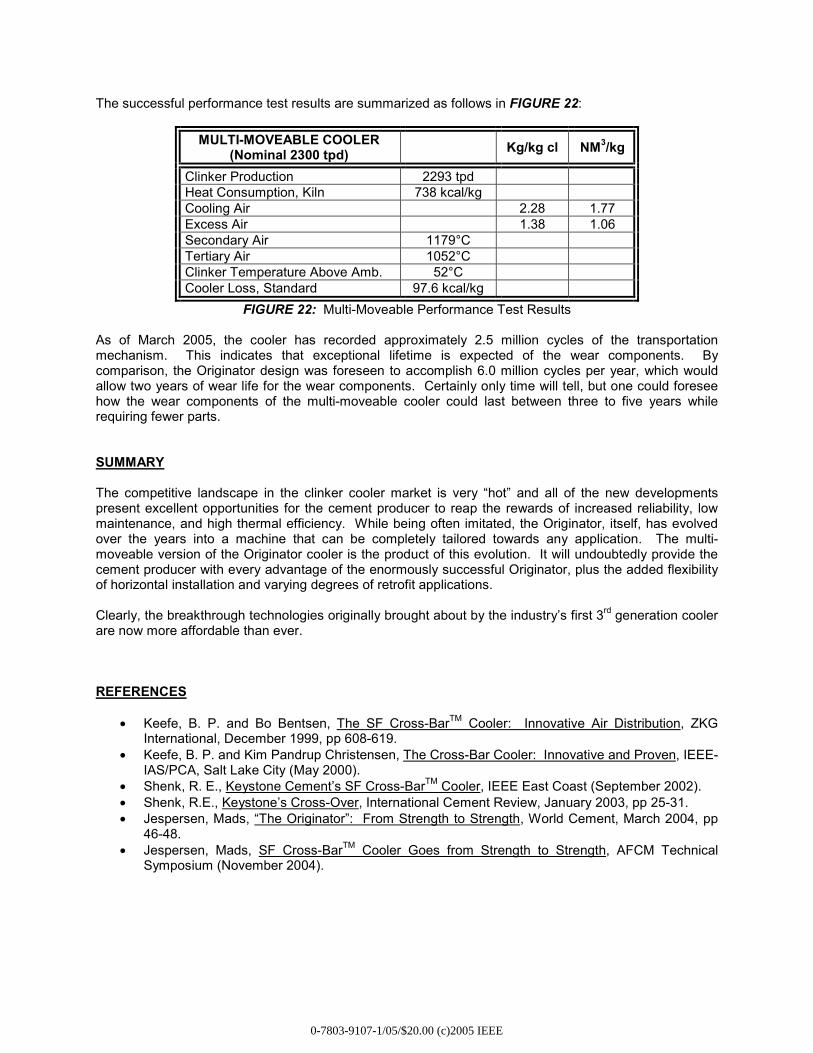
The successful performance test results are summarized as follows in FIGURE 22:
MULTI-MOVEABLE COOLER (Nominal 2300 tpd) Kg/kg cl NM3/kg
Clinker Production 2293 tpd Heat Consumption, Kiln 738 kcal/kg Cooling Air 2.28 1.77 Excess Air 1.38 1.06 Secondary Air 1179°C Tertiary Air 1052°C Clinker Temperature Above Amb. 52°C Cooler Loss, Standard 97.6 kcal/kg
FIGURE 22: Multi-Moveable Performance Test Results
As of March 2005, the cooler has recorded approximately 2.5 million cycles of the transportation mechanism. This indicates that exceptional lifetime is expected of the wear components. By comparison, the Originator design was foreseen to accomplish 6.0 million cycles per year, which would allow two years of wear life for the wear components. Certainly only time will tell, but one could foresee how the wear components of the multi-moveable cooler could last between three to five years while requiring fewer parts. SUMMARY The competitive landscape in the clinker cooler market is very “hot” and all of the new developments present excellent opportunities for the cement producer to reap the rewards of increased reliability, low maintenance, and high thermal efficiency. While being often imitated, the Originator, itself, has evolved over the years into a machine that can be completely tailored towards any application. The multi-moveable version of the Originator cooler is the product of this evolution. It will undoubtedly provide the cement producer with every advantage of the enormously successful Originator, plus the added flexibility of horizontal installation and varying degrees of retrofit applications. Clearly, the breakthrough technologies originally brought about by the industry’s first 3rd generation cooler are now more affordable than ever. REFERENCES
• Keefe, B. P. and Bo Bentsen, The SF Cross-BarTM Cooler: Innovative Air Distribution, ZKG International, December 1999, pp 608-619.
• Keefe, B. P. and Kim Pandrup Christensen, The Cross-Bar Cooler: Innovative and Proven, IEEE-IAS/PCA, Salt Lake City (May 2000).
• Shenk, R. E., Keystone Cement’s SF Cross-BarTM Cooler, IEEE East Coast (September 2002). • Shenk, R.E., Keystone’s Cross-Over, International Cement Review, January 2003, pp 25-31. • Jespersen, Mads, “The Originator”: From Strength to Strength, World Cement, March 2004, pp
46-48. • Jespersen, Mads, SF Cross-BarTM Cooler Goes from Strength to Strength, AFCM Technical
Symposium (November 2004).
0-7803-9107-1/05/$20.00 (c)2005 IEEE