Embed Size (px)
Citation preview
7/29/2019 0404_600
http://slidepdf.com/reader/full/0404600 1/21
TS 100 936 V6.0.0 (1998-08)
Technical Specification
Digital cellular telecommunications system (Phase 2+);Layer 1;
General requirements(GSM 04.04 version 6.0.0 Release 1997)
GLOBAL SYSTEM FOR
MOBILE COMMUNICATIONS
R
7/29/2019 0404_600
http://slidepdf.com/reader/full/0404600 2/21
ReferenceDTS/SMG-030404Q6 (8o003003.PDF)
KeywordsDigital cellular telecommunications system, Global System for Mobile
communications (GSM)
ETSI
Postal address
F-06921 Sophia Antipolis Cedex - FRANCE
Office address
650 Route des Lucioles - Sophia AntipolisValbonne - FRANCE
Tel.: +33 4 92 94 42 00 Fax: +33 4 93 65 47 16
Siret N° 348 623 562 00017 - NAF 742 C Association à but non lucratif enregistrée à laSous-Préfecture de Grasse (06) N° 7803/88
Internet
[email protected] http://www.etsi.fr
http://www.etsi.org
Copyright Notification
No part may be reproduced except as authorized by written permission.The copyright and the foregoing restriction extend to reproduction in
all media.
© European Telecommunications Standards Institute 1998.All rights reserved.
7/29/2019 0404_600
http://slidepdf.com/reader/full/0404600 3/21
Contents
Contents....................................................................................................................................................3
Intellectual Property Rights.......................................................................................................................4Foreword...................................................................................................................................................4
1 Scope......................................................................................................................................................51.1 Normative references........................................................................................................................................... ..51.2 Definitions and abbreviations................................................................................................................................7
2 Interfaces to the physical layer...............................................................................................................72.1 Interface to the Data Link Layer...........................................................................................................................72.1a Interface to the Radio Link Control and Medium Access Control layer ...........................................................72.2 Interface to radio resource management...............................................................................................................82.3 Interface to other functional units.........................................................................................................................8
3 Service of the physical layer...................................................................................................................8
3.1 Service Access Point............................................................................................................................................. .83.2 Service of the physical layer..................................................................................................................................93.2.1 Specific services of the physical layer in the MS.............................................................................................10
4 Primitives of the physical layer.............................................................................................................104.1 Generic names of primitives between layers 1 and 2 for the transfer of layer 2 frames and RLC/MAC blocks
...................................................................................................................................................................104.2 Generic names of primitives between layer 1 and the RR- management entity of layer 3................................114.3 Primitive types.....................................................................................................................................................114.4 Parameter definition............................................................................................................................................11
5 Physical layer procedures.....................................................................................................................135.1 States of the physical layer..................................................................................................................................135.2 Control procedures...............................................................................................................................................13
5.3 Physical layer interface procedures.....................................................................................................................14
6 Physical layer protocol header..............................................................................................................146.1 Physical layer protocol fields and procedures.....................................................................................................14
7 Block transmission...............................................................................................................................147.1 SACCH downlink block format..........................................................................................................................147.2 SACCH uplink block format...............................................................................................................................157.3 FACCH/SDCCH/CCCH/BCCH/CBCH downlink block format.................................................................... ....157.4 FACCH/SDCCH uplink block format.................................................................................................................167.5 PBCCH/PCCCH downlink/PACCH/PDTCH block type 1 (CS-1) format .................................................... ....167.6 PDTCH block type 2 (CS-2) format .............................................................................................................. .....167.7 PDTCH block type 3 (CS-3) format .............................................................................................................. .....177.8 PDTCH block type 4 (CS-4) format .............................................................................................................. .....17
7.9 PRACH uplink/PACCH uplink short acknowledgement block formats ...........................................................177.10 PTCCH downlink block format ........................................................................................................................187.11 PTCCH uplink block formats ...........................................................................................................................187.12 Order of bit transmission...................................................................................................................................19
8 Vocabulary...........................................................................................................................................19
Annex A (informative):Document change history......................................................................20
History....................................................................................................................................................21
ETSI
TS 100 936 V6.0.0 (1998-08)3GSM 04.04 version 6.0.0 Release 1997
7/29/2019 0404_600
http://slidepdf.com/reader/full/0404600 4/21
Intellectual Property Rights
IPRs essential or potentially essential to the present document may have been declared to ETSI. The information pertaining to these essential IPRs, if any, is publicly available for ETSI members and non-members, and can be
found in SR 000 314: "Intellectual Property Rights (IPRs); Essential, or potentially Essential, IPRs notified to ETSI in respect of ETSI standards" , which is available free of charge from the ETSI Secretariat. Latest updates areavailable on the ETSI Web server (http://www.etsi.fr/ipr or http://www.etsi.org/ipr).
Pursuant to the ETSI IPR Policy, no investigation, including IPR searches, has been carried out by ETSI. Noguarantee can be given as to the existence of other IPRs not referenced in SR 000 314 (or the updates on the ETSIWeb server) which are, or may be, or may become, essential to the present document.
Foreword
This Technical Specification (TS) has been produced by the Special Mobile Group (SMG) of the EuropeanTelecommunications Standards Institute (ETSI).
This specification defines the services offered by the physical layer (layer 1) of the Mobile Station - Base StationSystem (MS - BSS) interface within the digital cellular telecommunications system.
The contents of this TS is subject to continuing work within SMG and may change following formal SMG approval.Should SMG modify the contents of this TS, it will be re-released by SMG with an identifying change of release dateand an increase in version number as follows:
Version 6.x.y
where:
6 indicates GSM Phase 2+ Release 1997;
x the second digit is incremented for all other types of changes, i.e. technical enhancements, corrections,
updates, etc.;
y the third digit is incremented when editorial only changes have been incorporated in the specification.
7/29/2019 0404_600
http://slidepdf.com/reader/full/0404600 5/21
1 Scope
This Technical Specification (TS) defines the service offered by the physical layer (GSM 05-series of TechnicalSpecifications) of the MS-BS interface (GSM 05- and 04-series of Technical Specifications). Its main objective is to be
a guidance for the interface between the GSM Technical Specifications in the 05-series and the 04-series. It alsospecifies the format of signalling channels and the order of bit transmission.
As far as possible, this TS makes use of the layering principles of the Reference Model for Open SystemInterconnection (OSI) as contained in CCITT Recommendations X.200 and X.210.
1.1 Normative references
References may be made to:
a) specific versions of publications (identified by date of publication, edition number, version number, etc.), inwhich case, subsequent revisions to the referenced document do not apply; or
b) all versions up to and including the identified version (identified by "up to and including" before the versionidentity); or
c) all versions subsequent to and including the identified version (identified by "onwards" following the versionidentity); or
d) publications without mention of a specific version, in which case the latest version applies.
A non-specific reference to an ETS shall also be taken to refer to later versions published as an EN with the samenumber.
[1] GSM 01.04: "Digital cellular telecommunications system (Phase 2+); Abbreviations andacronyms".
[2] GSM 02.11: "Digital cellular telecommunications system (Phase 2+); Service accessibility".
[3] GSM 03.13: "Digital cellular telecommunications system (Phase 2+); Discontinuous Reception(DRX) in the GSM system".
[4] GSM 03.20: "Digital cellular telecommunications system (Phase 2+); Security related network functions".
[5] GSM 04.01: "Digital cellular telecommunications system (Phase 2+); Mobile Station - BaseStation System (MS - BSS) interface; General aspects and principles".
[6] GSM 04.02: "Digital cellular telecommunications system (Phase 2+); GSM Public Land Mobile Network (PLMN) access reference configuration".
[7] GSM 04.03: "Digital cellular telecommunications system (Phase 2+); Mobile Station - Base
Station System (MS - BSS) interface Channel structures and access capabilities".
[8] GSM 04.05: "Digital cellular telecommunications system (Phase 2+); Data Link (DL) layer General aspects".
[9] GSM 04.06: "Digital cellular telecommunications system (Phase 2+); Mobile Station - BaseStation System (MS - BSS) interface; Data Link (DL) layer specification".
[10] GSM 04.07: "Digital cellular telecommunications system (Phase 2+); Mobile radio interfacesignalling layer 3; General aspects".
[11] GSM 04.08: "Digital cellular telecommunications system (Phase 2+); Mobile radio interfacelayer 3 specification".
[12] GSM 04.10: "Digital cellular telecommunications system (Phase 2+); Mobile radio interfacelayer 3 Supplementary services specification; General aspects".
[13] GSM 04.11: "Digital cellular telecommunications system (Phase 2+); Point-to-Point (PP) ShortMessage Service (SMS) support on mobile radio interface".
ETSI
TS 100 936 V6.0.0 (1998-08)5GSM 04.04 version 6.0.0 Release 1997
7/29/2019 0404_600
http://slidepdf.com/reader/full/0404600 6/21
[14] GSM 04.12: "Digital cellular telecommunications system (Phase 2+); Short Message Service CellBroadcast (SMSCB) support on the mobile radio interface".
[15] GSM 04.13: "Digital cellular telecommunications system (Phase 2+); Performance requirementson mobile radio interface".
[16] GSM 04.21: "Digital cellular telecommunications system (Phase 2+); Rate adaption on the
Mobile Station - Base Station System (MS - BSS) Interface".
[17] GSM 04.22: "Digital cellular telecommunications system (Phase 2+); Radio Link Protocol (RLP)for data and telematic services on the Mobile Station - Base Station System (MS - BSS) interfaceand the Base Station System - Mobile-services Switching Centre (BSS - MSC) interface".
[17a] GSM 04.60: "Digital cellular telecommunications system (Phase 2+); General Packet RadioService (GPRS); Mobile Station - Base Station System (MS-BSS) interface; Radio Link Controland Medium Access Control (RLC/MAC) layer specification".
[18] GSM 04.80: "Digital cellular telecommunications system (Phase 2+); Mobile radio interfacelayer 3 supplementary services specification; Formats and coding".
[19] GSM 04.81: "Digital cellular telecommunications system (Phase 2+); Line identification
supplementary services - Stage 3".
[20] GSM 04.82: "Digital cellular telecommunications system (Phase 2+); Call Forwarding (CF)supplementary services - Stage 3".
[21] GSM 04.83: "Digital cellular telecommunications system; Call Waiting (CW) and Call Hold(HOLD) supplementary services - Stage 3".
[22] GSM 04.84: "Digital cellular telecommunications system (Phase 2+); MultiParty (MPTY)supplementary services - Stage 3".
[23] GSM 04.85: "Digital cellular telecommunications system (Phase 2+); Closed User Group (CUG)supplementary services - Stage 3".
[24] GSM 04.86: "Digital cellular telecommunications system (Phase 2+); Advice of Charge (AoC)supplementary services - Stage 3".
[25] GSM 04.88: "Digital cellular telecommunications system (Phase 2+); Call Barring (CB)supplementary services - Stage 3".
[26] GSM 04.90: "Digital cellular telecommunications system (Phase 2+); UnstructuredSupplementary Services Data (USSD) - Stage 3".
[27] GSM 05.01: "Digital cellular telecommunications system (Phase 2+); Physical layer on the radio path; General description".
[28] GSM 05.02: "Digital cellular telecommunications system (Phase 2+); Multiplexing and multipleaccess on the radio path".
[29] GSM 05.03: "Digital cellular telecommunications system (Phase 2+); Channel coding".
[30] GSM 05.04: "Digital cellular telecommunications system (Phase 2+); Modulation".
[31] GSM 05.05: "Digital cellular telecommunications system (Phase 2+); Radio transmission andreception".
[32] GSM 05.08: "Digital cellular telecommunications system (Phase 2+); Radio subsystem link control".
[33] GSM 05.10: "Digital cellular telecommunications system (Phase 2+); Radio subsystemsynchronization".
[34] GSM 05.90: "Digital cellular telecommunications system; GSM Electro Magnetic Compatibility
(EMC) considerations".
[35] CCITT Recommendation X.200: "Reference Model of open systems interconnection for CCITTapplications".
7/29/2019 0404_600
http://slidepdf.com/reader/full/0404600 7/21
[36] CCITT Recommendation X.210: "Open systems interconnection layer service definitionconventions".
1.2 Definitions and abbreviations
Abbreviations used in this TS are listed in GSM 01.04.
2 Interfaces to the physical layer
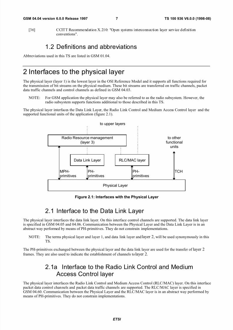
The physical layer (layer 1) is the lowest layer in the OSI Reference Model and it supports all functions required for the transmission of bit streams on the physical medium. These bit streams are transferred on traffic channels, packetdata traffic channels and control channels as defined in GSM 04.03.
NOTE: For GSM application the physical layer may also be referred to as the radio subsystem. However, theradio subsystem supports functions additional to those described in this TS.
The physical layer interfaces the Data Link Layer, the Radio Link Control and Medium Access Control layer and the
supported functional units of the application (figure 2.1).
Physical Layer
Data Link Layer RLC/MAC layer
Radio Resource management(layer 3)
to other functional
units
to upper layers
MPH-primitives PH-primitives PH-primitives TCH
Figure 2.1: Interfaces with the Physical Layer
2.1 Interface to the Data Link Layer
The physical layer interfaces the data link layer. On this interface control channels are supported. The data link layer is specified in GSM 04.05 and 04.06. Communication between the Physical Layer and the Data Link Layer is in anabstract way performed by means of PH-primitives. They do not constrain implementations.
NOTE: The terms physical layer and layer 1, and data link layer and layer 2, will be used synonymously in thisTS.
The PH-primitives exchanged between the physical layer and the data link layer are used for the transfer of layer 2frames. They are also used to indicate the establishment of channels to layer 2.
2.1a Interface to the Radio Link Control and Medium Access Control layer
The physical layer interfaces the Radio Link Control and Medium Access Control (RLC/MAC) layer. On this interface
packet data control channels and packet data traffic channels are supported. The RLC/MAC layer is specified inGSM 04.60. Communication between the Physical Layer and the RLC/MAC layer is in an abstract way performed bymeans of PH-primitives. They do not constrain implementations.
ETSI
TS 100 936 V6.0.0 (1998-08)7GSM 04.04 version 6.0.0 Release 1997
7/29/2019 0404_600
http://slidepdf.com/reader/full/0404600 8/21
The PH-primitives exchanged between the physical layer and the RLC/MAC layer are used for the transfer of RLC/MAC blocks. They are also used to indicate the establishment of packet data physical channels to the RLC/MAClayer.
2.2 Interface to radio resource management
The physical layer interfaces the radio resource management (RR-management) entity of layer 3 in the MS and in thenetwork.
Communication is performed in an abstract way by means of MPH-primitives. They do not constrain implementations.
The primitives exchanged with the RR-management entity are related to the assignment of channels, physical layer system information (including measurement results), etc.
2.3 Interface to other functional units
The physical layer interfaces other functional units in the MS and in the network for supporting traffic channels.These interfaces are described in the 06 and 07 series of Technical Specifications.
3 Service of the physical layer
The physical layer supports transfer of bit streams on the radio medium according to the Technical Specifications of the 05-series. The scope of the 05-series of Technical Specifications is the definition of a framework for operation onthe radio medium. The application of this framework on the radio medium results in a transmission service. Generalcharacteristics of the service obtained by applying the framework of the 05-series at the operation on the radio mediumare described in this clause.
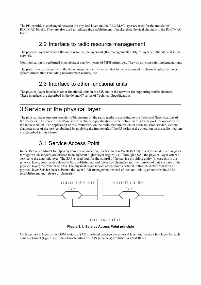
3.1 Service Access Point
In the Reference Model for Open System Interconnection, Service Access Points (SAPs) of a layer are defined as gatesthrough which services are offered to an adjacent higher layer (figure 3.1). Through a SAP the physical layer offers aservice to the data link layer. The SAP is used both for the control of the service providing entity (in case this is the physical layer; commands related to the establishment and release of channels) and the transfer of data (in case of the physical layer; the transfer of bits). The physical layer service access points defined in this TS differ from the OSI physical layer Service Access Points; the layer 3 RR-management instead of the data link layer controls the SAPs(establishment and release of channels).
t r a n s m i s s i o n m e d i u m
a d j a c e n t h i g h e r l a y e r a d j a c e n t h i g h e r l a y e r
S A P S A P
Figure 3.1: Service Access Point principle
On the physical layer of the GSM system a SAP is defined between the physical layer and the data link layer for eachcontrol channel (figure 3.2). The characteristics of SAPs (channels) are listed in GSM 04.03.
7/29/2019 0404_600
http://slidepdf.com/reader/full/0404600 9/21
P h y s i c a l l a y e r
B C C H P C H + A G C H R A C H S D C C H S A C C H F A C C H
D a t a L i n k L a y e r
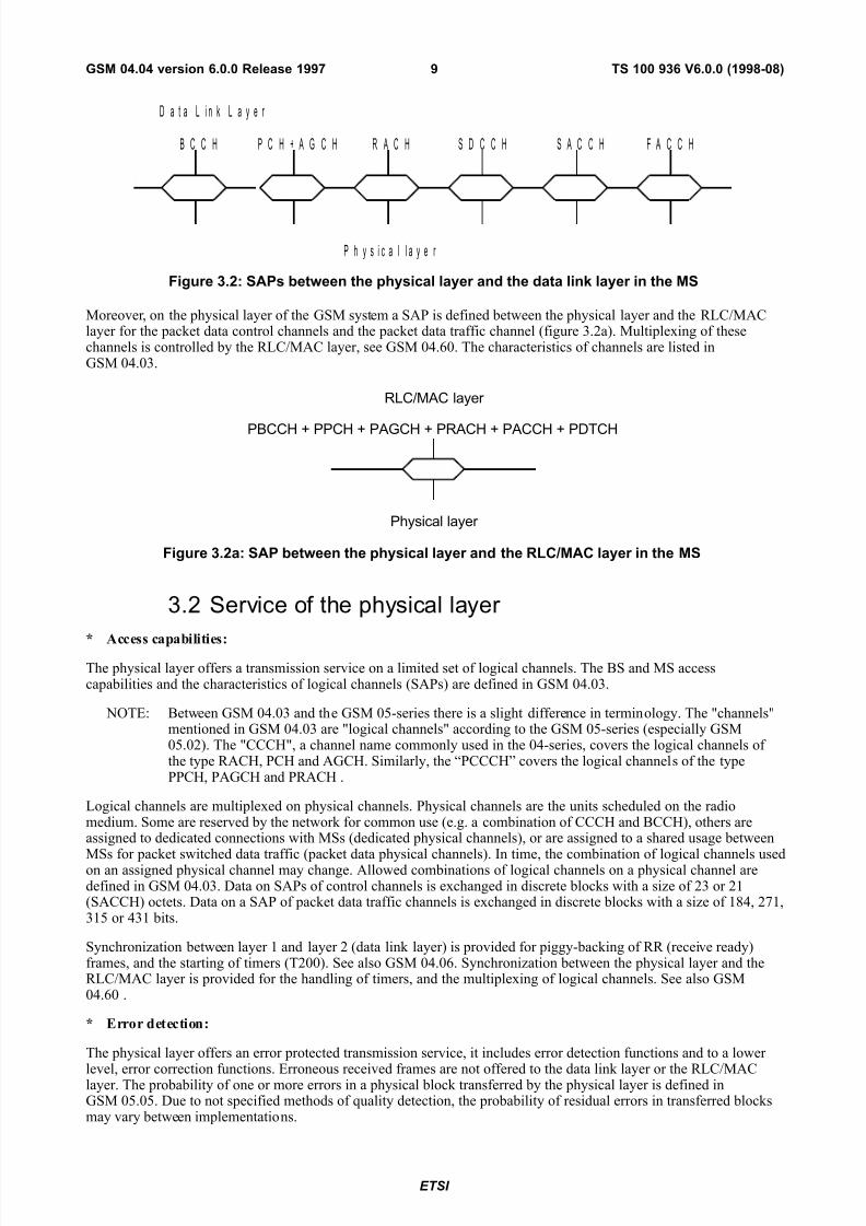
Figure 3.2: SAPs between the physical layer and the data link layer in the MS
Moreover, on the physical layer of the GSM system a SAP is defined between the physical layer and the RLC/MAClayer for the packet data control channels and the packet data traffic channel (figure 3.2a). Multiplexing of thesechannels is controlled by the RLC/MAC layer, see GSM 04.60. The characteristics of channels are listed inGSM 04.03.
Physical layer
RLC/MAC layer
PBCCH + PPCH + PAGCH + PRACH + PACCH + PDTCH
Figure 3.2a: SAP between the physical layer and the RLC/MAC layer in the MS
3.2 Service of the physical layer
* Access capabilities:
The physical layer offers a transmission service on a limited set of logical channels. The BS and MS accesscapabilities and the characteristics of logical channels (SAPs) are defined in GSM 04.03.
NOTE: Between GSM 04.03 and the GSM 05-series there is a slight difference in terminology. The "channels"mentioned in GSM 04.03 are "logical channels" according to the GSM 05-series (especially GSM05.02). The "CCCH", a channel name commonly used in the 04-series, covers the logical channels of the type RACH, PCH and AGCH. Similarly, the “PCCCH” covers the logical channels of the typePPCH, PAGCH and PRACH .
Logical channels are multiplexed on physical channels. Physical channels are the units scheduled on the radiomedium. Some are reserved by the network for common use (e.g. a combination of CCCH and BCCH), others areassigned to dedicated connections with MSs (dedicated physical channels), or are assigned to a shared usage between
MSs for packet switched data traffic (packet data physical channels). In time, the combination of logical channels usedon an assigned physical channel may change. Allowed combinations of logical channels on a physical channel aredefined in GSM 04.03. Data on SAPs of control channels is exchanged in discrete blocks with a size of 23 or 21(SACCH) octets. Data on a SAP of packet data traffic channels is exchanged in discrete blocks with a size of 184, 271,315 or 431 bits.
Synchronization between layer 1 and layer 2 (data link layer) is provided for piggy-backing of RR (receive ready)frames, and the starting of timers (T200). See also GSM 04.06. Synchronization between the physical layer and theRLC/MAC layer is provided for the handling of timers, and the multiplexing of logical channels. See also GSM04.60 .
* Error detection:
The physical layer offers an error protected transmission service, it includes error detection functions and to a lower
level, error correction functions. Erroneous received frames are not offered to the data link layer or the RLC/MAClayer. The probability of one or more errors in a physical block transferred by the physical layer is defined inGSM 05.05. Due to not specified methods of quality detection, the probability of residual errors in transferred blocksmay vary between implementations.
ETSI
TS 100 936 V6.0.0 (1998-08)9GSM 04.04 version 6.0.0 Release 1997
7/29/2019 0404_600
http://slidepdf.com/reader/full/0404600 10/21
* Encryption:
Security related functions implemented at the physical layer are described in GSM 03.20.
An overview of the functions specified in the 05-series which create the service of the physical layer can be found inGSM 05.01.
3.2.1 Specific services of the physical layer in the MS
The access capability service of the physical layer in the MS differs depending on the nature of the channel (traffic, packet data traffic or broadcast/common channels).
- Establishment of dedicated physical channels:
Establishment of dedicated physical channels on the physical layer is controlled by the radio resources management of layer 3 (GSM 04.08). During operation on a dedicated physical channel, the physical layer measures the signals of neighbouring base stations and the signal quality of the used dedicated physical channel. Measurements aretransferred to layer 3, measurement control information is offered by layer 3.
- Establishment of packet data physical channels :
Establishment of packet data physical channels on the physical layer is controlled by the radio resource managementof layer 3. Packet access and the reservation of radio resource on packet data physical channels is controlled by theRLC/MAC layer in co-operation with layer 3 (GSM 04.60 and GSM 04.08). During operation on packet data physicalchannels, the physical layer measures the signals of neighbouring base stations and the signal quality of the used packet data physical channel. Measurements are transferred to layer 3, measurement control information is offered bylayer 3.
- cell/PLMN selection in idle mode or in packet mode:
In idle mode or in packet mode, the physical layer selects the best cell with its BCCH/CCCH in close co-operationwith layer 3, meeting requirements for PLMN selection specified in GSM 02.11. The idle mode procedures are notmodelled within this TS. Examples of procedures for cell selection are described in GSM 05.08. The physical layer performs automatic crossover.
4 Primitives of the physical layer
The Physical layer interacts with other entities as illustrated in figure 2.1. The interactions with the data link layer of Dm channels and the interactions with the RLC/MAC layer of packet data physical channels are shown in terms of primitives where the primitives represent the logical exchange of information and control between the physical layer and adjacent layers. They do not specify or constrain implementations. The interactions between the physical layer andlayer 1 entities for Bm/Lm channels are for further study. For the physical layer two sets of primitives are defined:
- Primitives between physical layer and data link layer and RLC/MAC layer respectively:
PH - Generic name - Type: Parameters.
- Primitives between layer 1 and the RR-management layer 3 entity:
MPH - Generic name - Type: Parameters.
4.1 Generic names of primitives between layers 1 and 2 for the transfer of layer 2 frames and RLC/MAC blocks
The following primitive generic names are defined on the SAPs between the physical layer and the data link layer:
a) PH-DATA:
The PH-DATA primitives are used on a SAP to pass message units containing frames used for data link layer
and RLC/MAC layer respective peer-to-peer communications to and from the physical layer.
b) PH-RANDOM ACCESS:
7/29/2019 0404_600
http://slidepdf.com/reader/full/0404600 11/21
The PH-RANDOM ACCESS (PH-RA) primitives are used on the SAP of the RACH and the PRACH to requestand confirm (in the MS) the sending of a random access frame and to indicate (in the network) the arrival of arandom access frame. The random access protocols are specified in GSM 04.08 and GSM 04.60 respectively.
c) PH-CONNECT:
The PH-CONNECT primitive is used on a SAP to indicate that the physical connection on the corresponding
control channel or packet data physical channel has been established.
d) PH-READY-TO-SEND:
The PH-READY-TO-SEND primitive is used by the physical layer to trigger, if applicable, piggy backing, thestart of timer for the data link layer or the RLC/MAC layer and the forwarding a data unit to the physical layer.It is passed to the upper layer just before a new physical block is transmitted.
e) PH-EMPTY-FRAME:
The PH-EMPTY-FRAME primitive can be used by the data link layer and the RLC/MAC layer to indicate thatno frame has to be transmitted after receiving the PH-READY-TO-SEND primitive. It enables polling of several upper layer entities by the physical layer and support DTX.
4.2 Generic names of primitives between layer 1 and theRR- management entity of layer 3
The following primitive generic name is defined between layer 1 and the RR-management entity of layer 3:
- MPH-INFORMATION:
MPH-INFORMATION (MPH-INFO) primitives are used for the control of the physical layer by theRR-management of layer 3. This information activates and deactivates, configures and deconfigures, throughconnects and disconnects physical and logical channels. It is also used for the transfer of measurements andmeasurement control information from layer 1 to layer 3.
4.3 Primitive types
The primitive types defined in this TS are:
a) REQUEST:
The REQUEST primitive type is used when a higher layer is requesting a service from a lower layer.
b) INDICATION:
The INDICATION primitive type is used by a layer providing a service to notify the next higher layer of activities in the layer. This activities are directly related to the occurrence of a REQUEST primitive on the peer-protocol side.
c) RESPONSE:
The RESPONSE primitive type is used by a layer to acknowledge receipt from the INDICATION primitivetype.
d) CONFIRM:
The CONFIRM primitive type is used by the layer providing the requested service to confirm that the activityhas been completed.
4.4 Parameter definition
Primitives contain a variable amount of parameters. The primitives with included parameters are listed in table 4.1.
ETSI
TS 100 936 V6.0.0 (1998-08)11GSM 04.04 version 6.0.0 Release 1997
7/29/2019 0404_600
http://slidepdf.com/reader/full/0404600 12/21
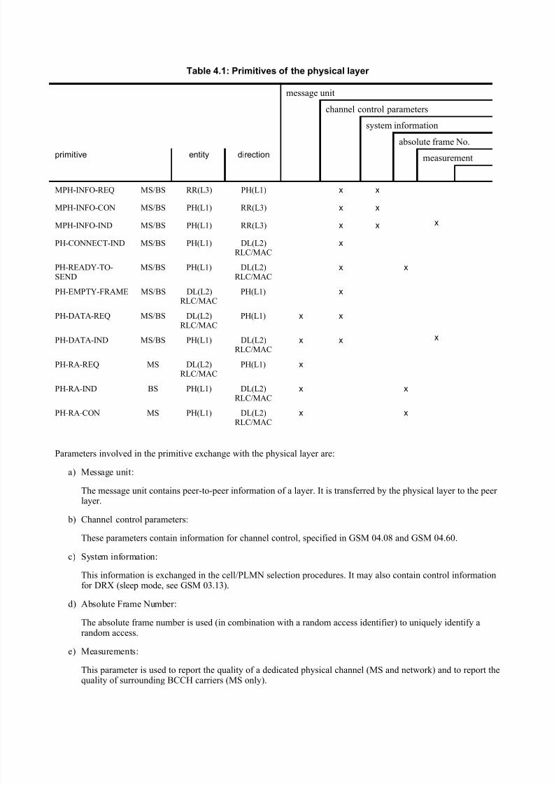
Table 4.1: Primitives of the physical layer
message unit
channel control parameters
system information
absolute frame No.
primitive entity direction measurement
MPH-INFO-REQ MS/BS RR(L3) PH(L1) x x
MPH-INFO-CON MS/BS PH(L1) RR(L3) x x
MPH-INFO-IND MS/BS PH(L1) RR(L3) x x x
PH-CONNECT-IND MS/BS PH(L1) DL(L2)RLC/MAC
x
PH-READY-TO-
SEND
MS/BS PH(L1) DL(L2)
RLC/MAC
x x
PH-EMPTY-FRAME MS/BS DL(L2)RLC/MAC
PH(L1) x
PH-DATA-REQ MS/BS DL(L2)RLC/MAC
PH(L1) x x
PH-DATA-IND MS/BS PH(L1) DL(L2)RLC/MAC
x x x
PH-RA-REQ MS DL(L2)RLC/MAC
PH(L1) x
PH-RA-IND BS PH(L1) DL(L2)RLC/MAC
x x
PH-RA-CON MS PH(L1) DL(L2)RLC/MAC
x x
Parameters involved in the primitive exchange with the physical layer are:
a) Message unit:
The message unit contains peer-to-peer information of a layer. It is transferred by the physical layer to the peer layer.
b) Channel control parameters:
These parameters contain information for channel control, specified in GSM 04.08 and GSM 04.60.
c) System information:
This information is exchanged in the cell/PLMN selection procedures. It may also contain control informationfor DRX (sleep mode, see GSM 03.13).
d) Absolute Frame Number:
The absolute frame number is used (in combination with a random access identifier) to uniquely identify arandom access.
e) Measurements:
This parameter is used to report the quality of a dedicated physical channel (MS and network) and to report thequality of surrounding BCCH carriers (MS only).
7/29/2019 0404_600
http://slidepdf.com/reader/full/0404600 13/21
5 Physical layer procedures
The main body of physical layer procedures is specified in GSM 04.08, GSM 04.60 and 05.08.
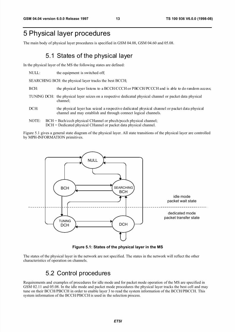
5.1 States of the physical layer In the physical layer of the MS the following states are defined:
NULL: the equipment is switched off;
SEARCHING BCH: the physical layer tracks the best BCCH;
BCH: the physical layer listens to a BCCH/CCCH or PBCCH/PCCCH and is able to do random access;
TUNING DCH: the physical layer seizes on a respective dedicated physical channel or packet data physicalchannel;
DCH: the physical layer has seized a respective dedicated physical channel or packet data physicalchannel and may establish and through connect logical channels.
NOTE: BCH = Bcch/ccch physical CHannel or pbcch/pccch physical channel;DCH = Dedicated physical CHannel or packet data physical channel.
Figure 5.1 gives a general state diagram of the physical layer. All state transitions of the physical layer are controlled by MPH-INFORMATION primitives.
NULL
BCH SEARCHING
BCH
TUNING
DCH DCH
idle modepacket wait state
dedicated modepacket transfer state
Figure 5.1: States of the physical layer in the MS
The states of the physical layer in the network are not specified. The states in the network will reflect the other characteristics of operation on channels.
5.2 Control procedures
Requirements and examples of procedures for idle mode and for packet mode operation of the MS are specified inGSM 02.11 and 05.08. In the idle mode and packet mode procedures the physical layer tracks the best cell and may
tune on their BCCH/PBCCH in order to enable layer 3 to read the system information of the BCCH/PBCCH. Thissystem information of the BCCH/PBCCH is used in the selection process.
ETSI
TS 100 936 V6.0.0 (1998-08)13GSM 04.04 version 6.0.0 Release 1997
7/29/2019 0404_600
http://slidepdf.com/reader/full/0404600 14/21
5.3 Physical layer interface procedures
Three types of primitives are defined for the communication between the physical layer and the data link layer both inthe MS and the network. When a control channel or a packet data physical channel is being established, aPH-CONNECT-INDICATION is offered to the data link layer or the RLC/MAC layer, the one which is applicable, onthe corresponding SAP. On an established full duplex control channel (DCCHs) in both MS and network, on an
established packet data physical channel or on the established BCCH/CCCH in the MS, physical blocks receivedcorrectly are offered on the corresponding SAP in PH-DATA-INDICATION primitives. On a full duplex controlchannel (DCCHs) or on the BCCH/CCCH in the network, the data link layer will offer physical blocks to betransmitted in PH-DATA-REQUEST primitives. On a packet data physical channel, the RLC/MAC layer will offer physical blocks to be transmitted in PH-DATA-REQUEST primitives. In the MS in idle mode or in packet wait state,random accesses on RACH or on PRACH can be offered in PH-RANDOM ACCESS-REQUEST primitives. The physical layer of the MS will perform a random access as soon as possible. The physical layer of the MS will confirmthe data link layer or the RLC/MAC layer, the one which is applicable, the transmission of the random access attemptin a PH-RANDOM ACCESS-CONFIRM. This confirmation contains the absolute frame number in which the randomaccess is transmitted. The physical layer of the BS offers correctly received random accesses to the data link layer or the RLC/MAC layer, the one which is applicable, in a PH-RANDOM ACCESS-INDICATION. This indicationcontains the absolute frame number in which the random access is received.
6 Physical layer protocol header
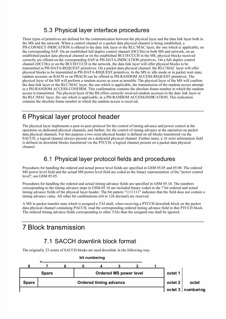
The physical layer implements a peer-to-peer protocol for the control of timing advance and power control at theoperation on dedicated physical channels, and further, for the control of timing advance at the operation on packetdata physical channels. For this purpose a two octet physical header is defined on all blocks transferred via theSACCH, a logical channel always present on a dedicated physical channel. Further more, a 16 octet information fieldis defined on downlink blocks transferred via the PTCCH, a logical channel present on a packet data physicalchannel .
6.1 Physical layer protocol fields and procedures
Procedures for handling the ordered and actual power level fields are specified in GSM 05.05 and 05.08. The orderedMS power level field and the actual MS power level field are coded as the binary representation of the "power controllevel", see GSM 05.05.
Procedures for handling the ordered and actual timing advance fields are specified in GSM 05.10. The numberscorresponding to the timing advance steps in GSM 05.10 are included binary coded in the 7 bit ordered and actualtiming advance fields of the physical layer header. The bit pattern "1111111" indicates that the field does not contain atiming advance value. All other bit combinations (64 to 126 decimal) are reserved.
A MS in packet transfer state which is assigned a TAI shall, when receiving a PTCCH downlink block on the packetdata physical channel containing PACCH, read the corresponding ordered timing advance field in that PTCCH block.The ordered timing advance fields corresponding to other TAIs than the assigned one shall be ignored .
7 Block transmission
7.1 SACCH downlink block format
The originally 23 octets of SACCH blocks are used downlink in the following way:
bit numbering<----------------------------------------------------------------------------------
8 7 6 5 4 3 2 1
Spare Ordered MS power level octet 1
Spare Ordered timing advance octet 2 octet
octet 3 numbering
7/29/2019 0404_600
http://slidepdf.com/reader/full/0404600 15/21
21octets V
: :
: :
: :
layer 2
frame octet 23
NOTE: The numbering convention specified in GSM 04.06 applies.
Figure 7.1: SACCH downlink block format
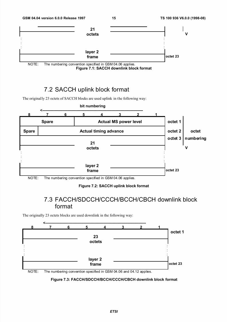
7.2 SACCH uplink block format
The originally 23 octets of SACCH blocks are used uplink in the following way:
bit numbering<----------------------------------------------------------------------------------
8 7 6 5 4 3 2 1
Spare Actual MS power level octet 1
Spare Actual timing advance octet 2 octet
octet 3 numbering21
octets V: :
: :
: :
layer 2
frame octet 23
NOTE: The numbering convention specified in GSM 04.06 applies.
Figure 7.2: SACCH uplink block format
7.3 FACCH/SDCCH/CCCH/BCCH/CBCH downlink blockformat
The originally 23 octets blocks are used downlink in the following way:
<----------------------------------------------------------------------------------8 7 6 5 4 3 2 1
octet 123
octets: :
: :
: :
layer 2
frame octet 23
NOTE: The numbering convention specified in GSM 04.06 and 04.12 applies.
Figure 7.3: FACCH/SDCCH/BCCH/CCCH/CBCH downlink block format
ETSI
TS 100 936 V6.0.0 (1998-08)15GSM 04.04 version 6.0.0 Release 1997
7/29/2019 0404_600
http://slidepdf.com/reader/full/0404600 16/21
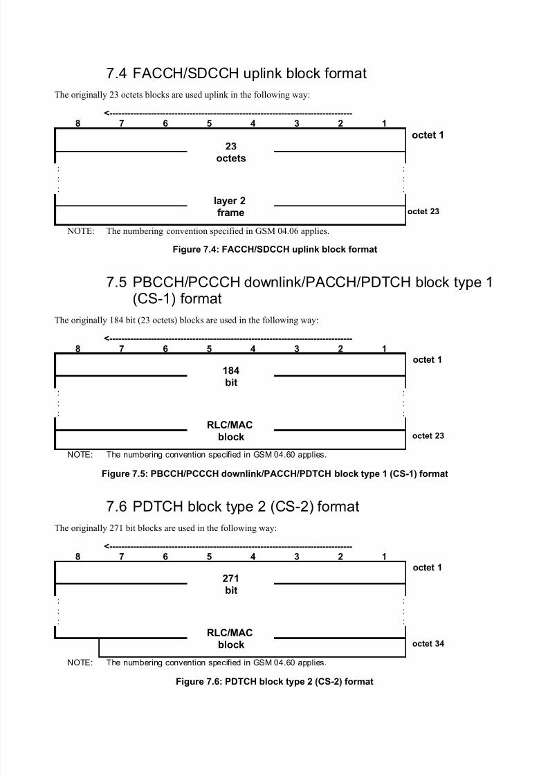
7.4 FACCH/SDCCH uplink block format
The originally 23 octets blocks are used uplink in the following way:
<----------------------------------------------------------------------------------8 7 6 5 4 3 2 1
octet 123
octets: :
: :
: :
layer 2frame octet 23
NOTE: The numbering convention specified in GSM 04.06 applies.
Figure 7.4: FACCH/SDCCH uplink block format
7.5 PBCCH/PCCCH downlink/PACCH/PDTCH block type 1(CS-1) format
The originally 184 bit (23 octets) blocks are used in the following way:
<----------------------------------------------------------------------------------8 7 6 5 4 3 2 1
octet 1
184bit
: :
: :
: :
RLC/MAC
block octet 23
NOTE: The numbering convention specified in GSM 04.60 applies.
Figure 7.5: PBCCH/PCCCH downlink/PACCH/PDTCH block type 1 (CS-1) format
7.6 PDTCH block type 2 (CS-2) format
The originally 271 bit blocks are used in the following way:
<----------------------------------------------------------------------------------8 7 6 5 4 3 2 1
octet 1
271bit
: :
: :
: :
RLC/MACblock octet 34
NOTE: The numbering convention specified in GSM 04.60 applies.
Figure 7.6: PDTCH block type 2 (CS-2) format
7/29/2019 0404_600
http://slidepdf.com/reader/full/0404600 17/21
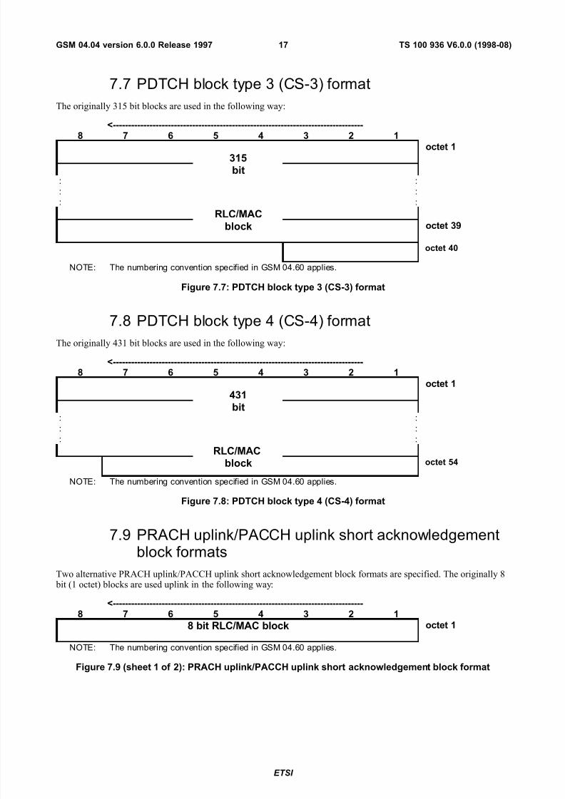
7.7 PDTCH block type 3 (CS-3) format
The originally 315 bit blocks are used in the following way:
<----------------------------------------------------------------------------------
8 7 6 5 4 3 2 1 octet 1
315bit
: :
: :
: :
RLC/MAC
block octet 39
octet 40
NOTE: The numbering convention specified in GSM 04.60 applies.
Figure 7.7: PDTCH block type 3 (CS-3) format
7.8 PDTCH block type 4 (CS-4) format
The originally 431 bit blocks are used in the following way:
<----------------------------------------------------------------------------------8 7 6 5 4 3 2 1
octet 1
431bit
: :: :
: :
RLC/MACblock octet 54
NOTE: The numbering convention specified in GSM 04.60 applies.
Figure 7.8: PDTCH block type 4 (CS-4) format
7.9 PRACH uplink/PACCH uplink short acknowledgement
block formatsTwo alternative PRACH uplink/PACCH uplink short acknowledgement block formats are specified. The originally 8 bit (1 octet) blocks are used uplink in the following way:
<----------------------------------------------------------------------------------8 7 6 5 4 3 2 1
8 bit RLC/MAC block octet 1
NOTE: The numbering convention specified in GSM 04.60 applies.
Figure 7.9 (sheet 1 of 2): PRACH uplink/PACCH uplink short acknowledgement block format
ETSI
TS 100 936 V6.0.0 (1998-08)17GSM 04.04 version 6.0.0 Release 1997
7/29/2019 0404_600
http://slidepdf.com/reader/full/0404600 18/21
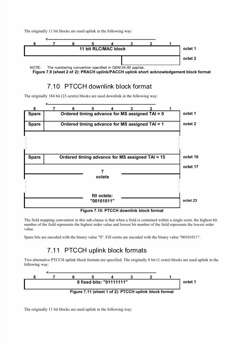
The originally 11 bit blocks are used uplink in the following way:
<----------------------------------------------------------------------------------8 7 6 5 4 3 2 1
11 bit RLC/MAC block octet 1
octet 2
NOTE: The numbering convention specified in GSM 04.60 applies.
Figure 7.9 (sheet 2 of 2): PRACH uplink/PACCH uplink short acknowledgement block format
7.10 PTCCH downlink block format
The originally 184 bit (23 octets) blocks are used downlink in the following way:
<----------------------------------------------------------------------------------8 7 6 5 4 3 2 1
Spare Ordered timing advance for MS assigned TAI = 0 octet 1
Spare Ordered timing advance for MS assigned TAI = 1 octet 2
: :: :: :
Spare Ordered timing advance for MS assigned TAI = 15 octet 16
7octet 17
octets: :: :
: :
fill octets:"00101011" octet 23
Figure 7.10: PTCCH downlink block format
The field mapping convention in this sub-clause is that when a field is contained within a single octet, the highest bitnumber of the field represents the highest order value and lowest bit number of the field represents the lowest order value.
Spare bits are encoded with the binary value "0". Fill octets are encoded with the binary value "00101011".
7.11 PTCCH uplink block formats
Two alternative PTCCH uplink block formats are specified. The originally 8 bit (1 octet) blocks are used uplink in thefollowing way:
<----------------------------------------------------------------------------------8 7 6 5 4 3 2 1
8 fixed bits: "01111111" octet 1
Figure 7.11 (sheet 1 of 2): PTCCH uplink block format
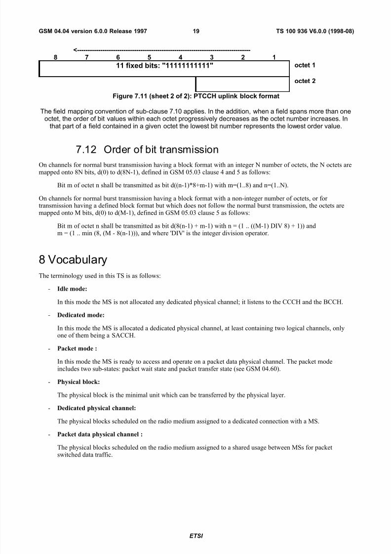
The originally 11 bit blocks are used uplink in the following way:
7/29/2019 0404_600
http://slidepdf.com/reader/full/0404600 19/21
<----------------------------------------------------------------------------------8 7 6 5 4 3 2 1
11 fixed bits: "11111111111" octet 1
octet 2
Figure 7.11 (sheet 2 of 2): PTCCH uplink block format
The field mapping convention of sub-clause 7.10 applies. In the addition, when a field spans more than oneoctet, the order of bit values within each octet progressively decreases as the octet number increases. In
that part of a field contained in a given octet the lowest bit number represents the lowest order value.
7.12 Order of bit transmission
On channels for normal burst transmission having a block format with an integer N number of octets, the N octets aremapped onto 8N bits, d(0) to d(8N-1), defined in GSM 05.03 clause 4 and 5 as follows:
Bit m of octet n shall be transmitted as bit d((n-1)*8+m-1) with m=(1..8) and n=(1..N).
On channels for normal burst transmission having a block format with a non-integer number of octets, or for transmission having a defined block format but which does not follow the normal burst transmission, the octets aremapped onto M bits, d(0) to d(M-1), defined in GSM 05.03 clause 5 as follows:
Bit m of octet n shall be transmitted as bit d(8(n-1) + m-1) with n = (1 .. ((M-1) DIV 8) + 1)) andm = (1 .. min (8, (M - 8(n-1))), and where 'DIV' is the integer division operator.
8 Vocabulary
The terminology used in this TS is as follows:
- Idle mode:
In this mode the MS is not allocated any dedicated physical channel; it listens to the CCCH and the BCCH.
- Dedicated mode:
In this mode the MS is allocated a dedicated physical channel, at least containing two logical channels, onlyone of them being a SACCH.
- Packet mode :
In this mode the MS is ready to access and operate on a packet data physical channel. The packet modeincludes two sub-states: packet wait state and packet transfer state (see GSM 04.60).
- Physical block:
The physical block is the minimal unit which can be transferred by the physical layer.
- Dedicated physical channel:
The physical blocks scheduled on the radio medium assigned to a dedicated connection with a MS.
- Packet data physical channel :
The physical blocks scheduled on the radio medium assigned to a shared usage between MSs for packetswitched data traffic.
ETSI
TS 100 936 V6.0.0 (1998-08)19GSM 04.04 version 6.0.0 Release 1997

7/29/2019 0404_600
http://slidepdf.com/reader/full/0404600 20/21
Annex A (informative):Document change history
SPEC SMG# CR PHASE VERS NEW_VERS SUBJECT
04.04 s24 A001 R97 5.0.1 6.0.0 Introduction of GPRS
7/29/2019 0404_600
http://slidepdf.com/reader/full/0404600 21/21
History
Document history
V6.0.0 August 1998 Publication
ISBN 2-7437-2459-5Dépôt légal : Août 1998
TS 100 936 V6.0.0 (1998-08)21GSM 04.04 version 6.0.0 Release 1997


