Embed Size (px)
Citation preview

7/29/2019 03 Presentation Chapter 3 Material
http://slidepdf.com/reader/full/03-presentation-chapter-3-material 1/235
1
CHAPTER 2
Materials of Chemical
Equipments

7/29/2019 03 Presentation Chapter 3 Material
http://slidepdf.com/reader/full/03-presentation-chapter-3-material 2/235
2
What is Materials Technology?
Materials technology is a relatively comprehensive disciplinethat begins with the production of goods from raw materials to
processing of materials into the shapes and forms needed for
specific applications.
MaterialRaw material Equipment
State changing
Energy,
Additives
Processing/Manufacturing
Energy,
Additives
Raw material into material :

7/29/2019 03 Presentation Chapter 3 Material
http://slidepdf.com/reader/full/03-presentation-chapter-3-material 3/235
3
Material Engineering : Material Science – Material TechnologyScience :
•Material Structure•Material Propeties•Relationship between Internal Structure & Propeties
Technology : – Processing from Raw Material into Material – Application – Design and new development.

7/29/2019 03 Presentation Chapter 3 Material
http://slidepdf.com/reader/full/03-presentation-chapter-3-material 4/235
4

7/29/2019 03 Presentation Chapter 3 Material
http://slidepdf.com/reader/full/03-presentation-chapter-3-material 5/235
5

7/29/2019 03 Presentation Chapter 3 Material
http://slidepdf.com/reader/full/03-presentation-chapter-3-material 6/235
2.1 Metal and Alloy Metal
• Iron and Steel
• Steel structure• Carbon Steel & Cast Iron
• Crystal Structure
• Mixture & Impurities

7/29/2019 03 Presentation Chapter 3 Material
http://slidepdf.com/reader/full/03-presentation-chapter-3-material 7/235
Iron and steel
Applications:
Cutting tools, pressure vessels, bolts, hammers, gears, cutlery,
jet engine parts, car bodies, screws, concrete reinforcement, ‘tin’
cans, bridges...
Why?
• Ore is cheap and abundant
• Processing techniques are economical (extraction, refining,
alloying, fabrication)
• High strength
• Very versatile metallurgy - a wide range of mechanical and
physical properties can be achieved, and these can be tailored to
the application

7/29/2019 03 Presentation Chapter 3 Material
http://slidepdf.com/reader/full/03-presentation-chapter-3-material 8/235
Disadvantages:
• Low corrosion resistance (use e.g. titanium, brass instead)
• High density: 7.9 g cm-3 (use e.g. aluminium,
magnesium instead)
• High temperature strength could be better (use nickel instead)
Basic distinction between ferrous andnon-ferrous alloys:
• Ferrous metals are ‘all-purpose’ alloys
• Non-ferrous metals used for niche applications,
where properties of ferrous metals are inadequate
Iron and steel

7/29/2019 03 Presentation Chapter 3 Material
http://slidepdf.com/reader/full/03-presentation-chapter-3-material 9/235
9
Steel structure
• Ferrite : (Ferrum), soft, easy to beprocessed at low temperature
• Austenite ( Roberts Austen), easy to beprocessed, non magnetic
• Zementite Fe3C : hard
• Ledeburite ( A. Ledebur): Structure at
Eutectic point, hard to be processed• Pearlite : Layer structure like pearl
layers

7/29/2019 03 Presentation Chapter 3 Material
http://slidepdf.com/reader/full/03-presentation-chapter-3-material 10/235

7/29/2019 03 Presentation Chapter 3 Material
http://slidepdf.com/reader/full/03-presentation-chapter-3-material 11/235
Carbon Steel and Cast Iron
A. According to their Chemical Components :
Iron Carbon Alloy:
(>95%)Fe +(0.05% ~ 4%)C +(~1%)(impure steel and cast iron)
B. According to the Carbon Content:Steel C%=0.02~2%
Cast Iron C%>2%
Engineering Pure Iron C%<0.02%
Pure Iron Steel Cast Iron
0.02 2 4 C%0
7/29/2019 03 Presentation Chapter 3 Material
http://slidepdf.com/reader/full/03-presentation-chapter-3-material 12/235
Isomeric Transformation of Pure Iron
is the phenomenon that the crystal configurationchanges with the temperature in the state of solid.

7/29/2019 03 Presentation Chapter 3 Material
http://slidepdf.com/reader/full/03-presentation-chapter-3-material 13/235
t < 910 Cubic Lattice in Bulk Center,℃
called “ -Fe”
t > 910 Cubic Lattice in Face Center,℃
called “ -Fe”
The transformation accomplishes in 910℃without temperatur changing.
Classification

7/29/2019 03 Presentation Chapter 3 Material
http://slidepdf.com/reader/full/03-presentation-chapter-3-material 14/235
The structure of iron-carbon alloy steel
The structure of iron-carbon alloy steel
The structure of metal
The micro-structure of metal
Grain Boundary
Grain
micrograph

7/29/2019 03 Presentation Chapter 3 Material
http://slidepdf.com/reader/full/03-presentation-chapter-3-material 15/235
Different structure cause different
performance of materials.

7/29/2019 03 Presentation Chapter 3 Material
http://slidepdf.com/reader/full/03-presentation-chapter-3-material 16/235
Steel metallurgy
Iron is allotropic / polymorphic i.e. exhibits different crystal
structures at different temperaturesMost importantly: bcc <-> fcc transformation at 912°C (for pure
iron)
Solubility of carbon in ferrite (α-iron, bcc): 0.02 wt%
austenite (γ-iron, fcc): 2.1 wt%
What happens to carbon when crystal structure transforms from
fcc to bcc?
Fundamental issue in metallurgy of low alloy
steels

7/29/2019 03 Presentation Chapter 3 Material
http://slidepdf.com/reader/full/03-presentation-chapter-3-material 17/235

7/29/2019 03 Presentation Chapter 3 Material
http://slidepdf.com/reader/full/03-presentation-chapter-3-material 18/235

7/29/2019 03 Presentation Chapter 3 Material
http://slidepdf.com/reader/full/03-presentation-chapter-3-material 19/235
Pearlite
NB Pearlite is a MIXTURE of phases (on a very fine scale)
Alternating layers of ferrite and cementite formedsimultaneously from the remaining austenite when
temperature reaches 723qC

7/29/2019 03 Presentation Chapter 3 Material
http://slidepdf.com/reader/full/03-presentation-chapter-3-material 20/235

7/29/2019 03 Presentation Chapter 3 Material
http://slidepdf.com/reader/full/03-presentation-chapter-3-material 21/235
Fe 1.3 wt% C: Cementite precipitates at austenite grainboundaries, remaining austenite is transformed into
pearlite
7/29/2019 03 Presentation Chapter 3 Material
http://slidepdf.com/reader/full/03-presentation-chapter-3-material 22/235

7/29/2019 03 Presentation Chapter 3 Material
http://slidepdf.com/reader/full/03-presentation-chapter-3-material 23/235

7/29/2019 03 Presentation Chapter 3 Material
http://slidepdf.com/reader/full/03-presentation-chapter-3-material 24/235
24
High mechanic performance if structure of grain arehomogeneous and „ tight“

7/29/2019 03 Presentation Chapter 3 Material
http://slidepdf.com/reader/full/03-presentation-chapter-3-material 25/235
25
Crystal of Ferrite Steel (
Atom Carbon in thestructure Ferrite
-Fe)

7/29/2019 03 Presentation Chapter 3 Material
http://slidepdf.com/reader/full/03-presentation-chapter-3-material 26/235
26
Atom chrom in the structure Ferrite
Crystal of Ferrite Steel ( -Fe)

7/29/2019 03 Presentation Chapter 3 Material
http://slidepdf.com/reader/full/03-presentation-chapter-3-material 27/235
27
Atom silicium in the structure Ferrite
Crystal of Ferrite Steel ( -Fe)

7/29/2019 03 Presentation Chapter 3 Material
http://slidepdf.com/reader/full/03-presentation-chapter-3-material 28/235
28
Crystal of Austenite Steel ( -Fe)
Atom Carbon in thestructure Austenite

7/29/2019 03 Presentation Chapter 3 Material
http://slidepdf.com/reader/full/03-presentation-chapter-3-material 29/235
29
Ferrit, lowmechanicendurance
Ferrit+ Perlit :0,35% C,temper steel
Perlit : 0,8% C,mold steel, bycooling of
Austenite
Structure of different metal crystal under microscope

7/29/2019 03 Presentation Chapter 3 Material
http://slidepdf.com/reader/full/03-presentation-chapter-3-material 30/235
30
Micrograph of Perlite & Zementite
1,3%C , tool steel
Micrograph of Austenite steelX10CrNi18.9
Structure of different metal crystal under microscope

7/29/2019 03 Presentation Chapter 3 Material
http://slidepdf.com/reader/full/03-presentation-chapter-3-material 31/235
α-Fe γ -Fe
910℃
The transformation

7/29/2019 03 Presentation Chapter 3 Material
http://slidepdf.com/reader/full/03-presentation-chapter-3-material 32/235
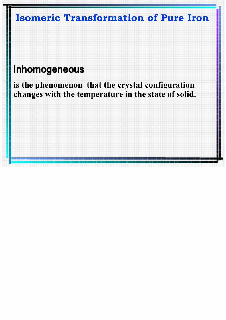
Iron-iron carbide equilibrium diagram

7/29/2019 03 Presentation Chapter 3 Material
http://slidepdf.com/reader/full/03-presentation-chapter-3-material 33/235
Austenite
A3
A1
Ferrite
Austenite+
Ferrite
Pearlite
+
908
722
Tem
perature
Iron-iron carbide equilibrium diagram
Percent carbon of weight
0 0.80.2 0.4 0.6

7/29/2019 03 Presentation Chapter 3 Material
http://slidepdf.com/reader/full/03-presentation-chapter-3-material 34/235
• The lattice structure of steel varies from one form toanother as the temperature changes.
• This is illustrated in the above diagram. Between roomtemperature and 722ºC, the steel consists of what isknown as “ferrite and pearlite”.
• Ferrite is a solid solution of a small amount of carbondissolved in iron. Pearlite, which is shown in thediagram, is a mixture of ferrite and iron carbide. Thecarbide is very hard and brittle.
• In the previous diagram between line A1 (lower criticaltemperature) and A3 (upper critical temperature) thecarbide dissolves more readily into the lattice that is nowcalled “Ferrite and austenite”. Austenite is a solidsolution of carbon and iron that is denser than ferrite.

7/29/2019 03 Presentation Chapter 3 Material
http://slidepdf.com/reader/full/03-presentation-chapter-3-material 35/235
Above line A3 the lattice is uniform in property with theaustenite the main structure. The actual temperature forthis austenite range is a function of the carbon content of the steel as shown in the figure.

7/29/2019 03 Presentation Chapter 3 Material
http://slidepdf.com/reader/full/03-presentation-chapter-3-material 36/235
The basic types of C existing in iron-carbon alloy:
Carbon and its existing form in steel
Dissolution
Chemical Combination
Blending

7/29/2019 03 Presentation Chapter 3 Material
http://slidepdf.com/reader/full/03-presentation-chapter-3-material 37/235
• C dissolute in the lattice of Fe to form
Solid Solution
—— Fe-C Solid Solution.
Solvent —— the element without changing in
lattice Fe is the solvent
Solute —— the element dissolving in solvent C is
the solute
Dissolution

7/29/2019 03 Presentation Chapter 3 Material
http://slidepdf.com/reader/full/03-presentation-chapter-3-material 38/235
Two kinds of common-used Solid Solution
Solubility of C
At room temperature 0.006 %
723 ℃ 0.02 %(maximum)
Ferrite(F):
The solid solution formed by C dissolving in -Fe is calledFerrite.
Characteristics:
Because the gap between atoms is small, the capacity todissolve C is weak.

7/29/2019 03 Presentation Chapter 3 Material
http://slidepdf.com/reader/full/03-presentation-chapter-3-material 39/235
Low strength
Low hardness
Good plasticity
Good toughness
aMP saMP b
170~90,280~200 == σ σ
aMP HB 0.8~5.5=
%40~30=δ
2/5.2~8.1 mMJ ak =
Properties

7/29/2019 03 Presentation Chapter 3 Material
http://slidepdf.com/reader/full/03-presentation-chapter-3-material 40/235
The solid solution formed by C dissolving in γ -Fe is called
Austenite, it is denser than Ferrite.The lattice of C keeps in that of γ -Fe, i.e. Cubic Lattice
in Face Center.
Characteristics:
Because the gap between atoms is large, the capacityto dissolve C is strong.
Solubility of C
723 ℃ 0.8 %
1147 ℃ 2.06 %(maximum)
Austenite(A)
7/29/2019 03 Presentation Chapter 3 Material
http://slidepdf.com/reader/full/03-presentation-chapter-3-material 41/235
High strength
High hardness
Good plasticity
Good toughness
No ironic magnetism
Properties

7/29/2019 03 Presentation Chapter 3 Material
http://slidepdf.com/reader/full/03-presentation-chapter-3-material 42/235
The transformation between F and A:
723 ~ 910℃Ferrite (F) Austenite (A)
Both F and A have good plasticity and they
are the structural basis of steels’ characteristicof excellent plasticity.
The irons that dissolve C will take the
transformation between -Fe and -Fe in
different temperature.

7/29/2019 03 Presentation Chapter 3 Material
http://slidepdf.com/reader/full/03-presentation-chapter-3-material 43/235
Chemical Combination:
C and Fe form the metallic compound ——Iron Carbide(Fe3C) whose crystal structure is called Cementite indicated
by “C”.
C + 3Fe Fe3C•Characteristics:
a)The carbon content of Cementite is high, the massproportion is 6.67%.
b)Hard and brittle (HB=78.4MPa)
c)Almost no plasticity and toughness
Cementite
7/29/2019 03 Presentation Chapter 3 Material
http://slidepdf.com/reader/full/03-presentation-chapter-3-material 44/235
a) Low break-down strength ( b≈35 MPa )b) The Cementite is semi-stable compound, it will
decompose into Fe and C at certain conditions, theextricated C exists in the form of graphite.
Fe3C C + 3Fe
Cementite

7/29/2019 03 Presentation Chapter 3 Material
http://slidepdf.com/reader/full/03-presentation-chapter-3-material 45/235
The alloy whose components are blending together
in the state of liquid can solidify into two types of mechanical mixtures:
a) Mixture formed by two solid solutions;
b) Mixture formed by a solid solution and
metallic compound.
Mechanical Blending (Mixture)
For example:
Pearlite (P),Ledeburite (L) is a kind of Mechanical Mixture.
Pearlite (P) = Ferrite (F) + Cementite (C)Ledeburite (L) = Austenite (A) + Cementite (C)

7/29/2019 03 Presentation Chapter 3 Material
http://slidepdf.com/reader/full/03-presentation-chapter-3-material 46/235
46
Damascus sword:
which Westerners first encountered during the Crusades
against the Muslim nations
7/29/2019 03 Presentation Chapter 3 Material
http://slidepdf.com/reader/full/03-presentation-chapter-3-material 47/235
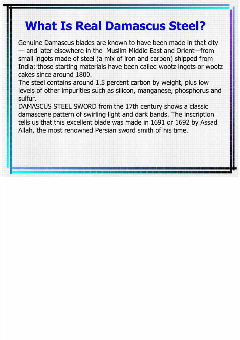
What Is Real Damascus Steel?
Genuine Damascus blades are known to have been made in that city — and later elsewhere in the Muslim Middle East and Orient—fromsmall ingots made of steel (a mix of iron and carbon) shipped fromIndia; those starting materials have been called wootz ingots or wootzcakes since around 1800.
The steel contains around 1.5 percent carbon by weight, plus lowlevels of other impurities such as silicon, manganese, phosphorus andsulfur.DAMASCUS STEEL SWORD from the 17th century shows a classicdamascene pattern of swirling light and dark bands. The inscriptiontells us that this excellent blade was made in 1691 or 1692 by Assad Allah, the most renowned Persian sword smith of his time.

7/29/2019 03 Presentation Chapter 3 Material
http://slidepdf.com/reader/full/03-presentation-chapter-3-material 48/235
Assemble the ingredients to load into thecrucible, including high-purity iron, Sorel iron,charcoal, glass chips and green leaves. The
quantity of carbon and impurity elements thatend up in the ingot is controlled by theproportions of iron, Sorel iron and charcoaladded to the mix.
Heat the crucible. During this process, theglass melts, forming a slag that protects theingot from oxidizing. The leaves generatehydrogen, which is known to acceleratecarburization of iron. The carbon content of the iron is raised to 1.5 percent, a goodproportion for forming the hard iron carbideparticles whose accretion into bands gives
Damascus blades their characteristic wavysurface pattern. The leaves and glass can beleft out, but ingots made without them aremore prone to cracking during hammering.
7/29/2019 03 Presentation Chapter 3 Material
http://slidepdf.com/reader/full/03-presentation-chapter-3-material 49/235
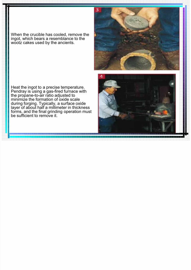
When the crucible has cooled, remove theingot, which bears a resemblance to thewootz cakes used by the ancients.
Heat the ingot to a precise temperature.Pendray is using a gas-fired furnace withthe propane-to-air ratio adjusted to
minimize the formation of oxide scaleduring forging. Typically, a surface oxidelayer of about half a millimeter in thicknessforms, and the final grinding operation mustbe sufficient to remove it.

7/29/2019 03 Presentation Chapter 3 Material
http://slidepdf.com/reader/full/03-presentation-chapter-3-material 50/235
Forge the ingot (deform it slightly with hammer blows while it is still hot). When the ingot gets
too cold to deform without cracking, heat it upandforge again. Four separate stages of the ingot areshown here; each stage is the result of severalcycles of heating and forging. A total of about 50cycles may be needed to bang out the blade shapefrom the ingot—a highly labor-intensive process.Pendray uses a modern air hammer. A handheld
hammer works, too, but it takes longer.
Cut the blade to final shape and hand-forgeto add finer details.

7/29/2019 03 Presentation Chapter 3 Material
http://slidepdf.com/reader/full/03-presentation-chapter-3-material 51/235
Remove the excess steel and thedecarburized surface metal. Pendray isusing an electric belt grinder for this step.
Cut grooves and drill holes into thesurface of the blade to createMohammed's ladder and rose
patterns, if desired. Forge the bladeflat again and polish the surface to givethe blade its near final form.

7/29/2019 03 Presentation Chapter 3 Material
http://slidepdf.com/reader/full/03-presentation-chapter-3-material 52/235
Etch blade surface with an acid to bring out the pattern; the softer steeldarkens, and the harder steel appears as brighter lines.

7/29/2019 03 Presentation Chapter 3 Material
http://slidepdf.com/reader/full/03-presentation-chapter-3-material 53/235
The impure elementsThe main impure elements are:
Mn is useful element.
Si is useful element.
S is harmful element.
P is harmful element.O is harmful element.
N is harmful element.
H is harmful element.

7/29/2019 03 Presentation Chapter 3 Material
http://slidepdf.com/reader/full/03-presentation-chapter-3-material 54/235
Mn < 0.8% (the common existing impure element)
Coming from the deoxidizing and desulfurizingagent in the process of smelting.
Function: eliminating S and O2.
• They won’t effect the properties of steels if the
content of both are little.
Manganese (Mn):
Mn > 0.8% ( the alloy element intentionally)
Function: Mn can disolve in the ferrite to formthe solid solution strengthening the effect of
ferrite.

7/29/2019 03 Presentation Chapter 3 Material
http://slidepdf.com/reader/full/03-presentation-chapter-3-material 55/235
Si < 0.5% (common existing impure element)
Coming from the deoxidizing agent and ore.
Function:
Ability of deoxidation is stronger than Mn.
2FeO + Si 2 Fe + SiO2
Si can dissolve in the Ferrite and improve the
strength and hardness of steels.
The existing form:
Forming solid solution with Ferrite.or Remaining in the steels in the form of
deoxidation product (SiO2)
Silicon (Si):
S l h (S)

7/29/2019 03 Presentation Chapter 3 Material
http://slidepdf.com/reader/full/03-presentation-chapter-3-material 56/235
Sulphur (S):• Originating in the fuels in ore or which are used in the
process of smelting (Coke).
• The existing form: FeS (S doesn’t dissolve in Fe)
• Function:
The low-melting-pointed compound (985ºC) formed by
FeS and Fe makes the steel unit crack in the process of hot-working, this phenomenon is called “Hot Brittle”.
Controlling of the content of S:
Common Steel : S 0.055 0.07%
High Grade Steel : S 0.03 0.045%
Super High Grade Steel : S 0.02 0.03%

7/29/2019 03 Presentation Chapter 3 Material
http://slidepdf.com/reader/full/03-presentation-chapter-3-material 57/235
Phosphorus (P):• Originating in the ore.
• Function:P in steels can dissolves in -Fe and improves the
strength of steels in normal atmospheric temperature
& brittleness, but dramatically reduces their plasticity
and toughness, this phenomenon is called “ColdBrittle”.
• When the content of P in the steel is P=0.3%, the
impact toughness ak = 0.
• Controlling of the content of P: P 0.06%

7/29/2019 03 Presentation Chapter 3 Material
http://slidepdf.com/reader/full/03-presentation-chapter-3-material 58/235
Oxygen (O2)
• Originating in the air.
• Existing form:
O2 always exists in the steels in the form of non-metallic
inclusion, such as FeO, SiO2 , MnO, MgO, Al2O3 , etc.
• Function:
These oxidations is in the steels as solid grains which
are hard but brittle and damage the continuity of basic
structure of steels sharply reducing the mechanical
property of steels.
• Eliminating the O2 in the process of smelting.

7/29/2019 03 Presentation Chapter 3 Material
http://slidepdf.com/reader/full/03-presentation-chapter-3-material 59/235
Nitrogen (N)• Originating in the air.
• Function: – Low Carbon Steels with high-content of N2 are
particularly lack of resistance to corrosion.
– Easy to form the air bubble to be loose.
– Cause the phenomenon of “Age-hardening”.
• Methods:
Adding Al and Ti to form AlN and TiN as if making the
N fix in the steels (called N-fixed Treatment), this will
eliminate the age-hardening.

7/29/2019 03 Presentation Chapter 3 Material
http://slidepdf.com/reader/full/03-presentation-chapter-3-material 60/235
Hydrogen (H2)
Originating in moist feed in steel-melting stove, pouring
system and the moist air, etc. Function:
– Making the steels to be brittle (H-Brittle)
– Making the steels to be seriously defective (Fish-eye)
Methods:
• Improve the environment of smelting.
• Clear up the moisture content in the feed.
• Purify the steel liquid.

7/29/2019 03 Presentation Chapter 3 Material
http://slidepdf.com/reader/full/03-presentation-chapter-3-material 61/235
2.2 Properties of Materials
61
Mechanical Properties
Physical Properties
Chemical PropertiesManufacturing Properties

7/29/2019 03 Presentation Chapter 3 Material
http://slidepdf.com/reader/full/03-presentation-chapter-3-material 62/235
Mechanical Properties:
62
Definition:The capability of materials to resist external forces,but does not deformation beyond allowance or wreck.
Main Performance Index:
Five Index:
Elasticity,Plasticity,
Strength,
Hardness,
Toughness

7/29/2019 03 Presentation Chapter 3 Material
http://slidepdf.com/reader/full/03-presentation-chapter-3-material 63/235
Mechanical properties
Ferrite: soft and ductile Cementite: hard andbrittle
M h i l P ti

7/29/2019 03 Presentation Chapter 3 Material
http://slidepdf.com/reader/full/03-presentation-chapter-3-material 64/235
Mechanical Properties:Elasticity
64
Elastic State(curve o-b)1.proportional limit:
2.elastic limit:
Tensile curve of Low Carbon steel
ε
ab
o
M h i l P ti

7/29/2019 03 Presentation Chapter 3 Material
http://slidepdf.com/reader/full/03-presentation-chapter-3-material 65/235
Mechanical Properties:Elasticity
7/29/2019 03 Presentation Chapter 3 Material
http://slidepdf.com/reader/full/03-presentation-chapter-3-material 66/235
Strength
66
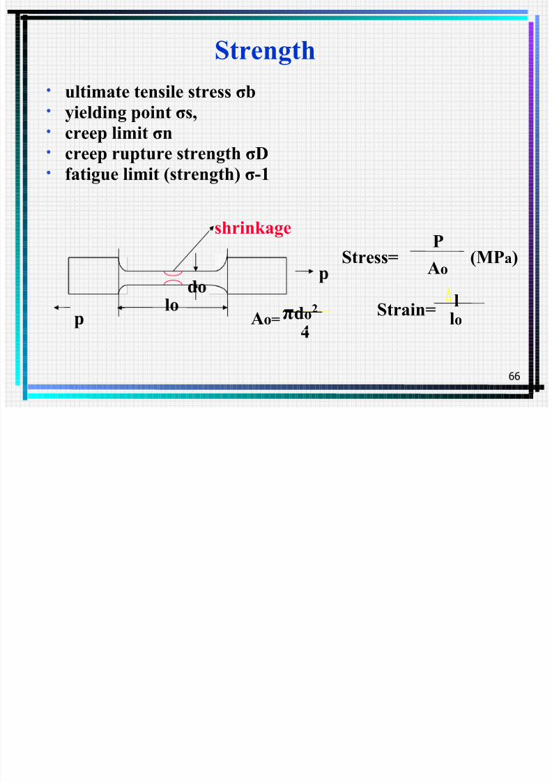
• ultimate tensile stress σb• yielding point σs,• creep limit σn• creep rupture strength σD• fatigue limit (strength) σ-1
p
p
shrinkage
dolo
4Ao= πdo2
P
AoStress= (MPa)
Strain=llo

7/29/2019 03 Presentation Chapter 3 Material
http://slidepdf.com/reader/full/03-presentation-chapter-3-material 67/235
1. Yielding State
(near point c)
o
s s
F
P =σ
2. Intensification State (curve c-d)
T. S. (Tensile Strength)
o
bb
F
P =σ
o F
P 2.02.0 =σ
Conditional Yielding
Mechanical Properties:When it is stretched to a certain degree,
there will be shrinkage ,and then break.
3. Shrink Neck State
(after d)

7/29/2019 03 Presentation Chapter 3 Material
http://slidepdf.com/reader/full/03-presentation-chapter-3-material 68/235
have no apparent yielding phenomena and :
σ 0.2 = stress in 0.2% of residue elongation
Mechanical Properties:Yielding Point σs (MPa)
- minimum value in yielding state
- plastic deformation appears.
Yielding point σ0.2
The stress of any point in the pressure vessel caused by pressurefrom medium should be below the elastic limit and cannot happen theplastic deformation.
7/29/2019 03 Presentation Chapter 3 Material
http://slidepdf.com/reader/full/03-presentation-chapter-3-material 69/235
The maximum value of stress from thebeginning of being stressed to the end of
fracture.
Mechanical Properties:
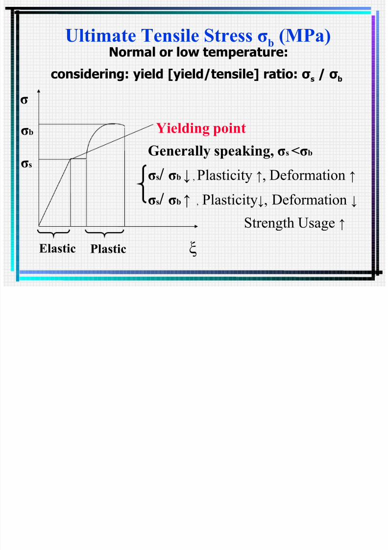
Ultimate Tensile Stress σb (MPa)
7/29/2019 03 Presentation Chapter 3 Material
http://slidepdf.com/reader/full/03-presentation-chapter-3-material 70/235
σb
σs
Elastic Plastic
σ
ξ
Yielding point
Normal or low temperature:
considering: yield [yield/tensile] ratio: σ s / σ b
Generally speaking, σs <σb
σs/ σb ↓ , Plasticity ↑, Deformation ↑
σs
/ σb
↑,
Plasticity↓, Deformation ↓Strength Usage ↑
Ultimate Tensile Stress σb (MPa)
Mechanical Properties:

7/29/2019 03 Presentation Chapter 3 Material
http://slidepdf.com/reader/full/03-presentation-chapter-3-material 71/235
Elevated temperature:
Creep Ratemm/mm*h(P con.)
Temperature(0
C)1Cr18Ni9Ti
425 475 520 550
10-6 176 91 33 6
considering: σ n and σ D as well as the previous
Mechanical Properties:
Creep Rate
M h i l P ti

7/29/2019 03 Presentation Chapter 3 Material
http://slidepdf.com/reader/full/03-presentation-chapter-3-material 72/235
Mechanical Properties:
Creep Limit σ n
The temperature in which metals creep
Creep phenomena:
When the materials is in high temperature and incertain stress, the stress increases as the time isgoing.
Carbon steel > 420
0
CAlloy steel > 4500C
Light metal and alloy > 50-1500C
Pt, Sn Normal Temperature

7/29/2019 03 Presentation Chapter 3 Material
http://slidepdf.com/reader/full/03-presentation-chapter-3-material 73/235
τ
ε
o
Mechanical Properties:
Creep Curve
ε
τ

7/29/2019 03 Presentation Chapter 3 Material
http://slidepdf.com/reader/full/03-presentation-chapter-3-material 74/235
Mechanical Properties:Creep limit σ n (MPa)
Definition: The ability of materials to resist theslowly plastic deformation under high temperature.
Under certain temperature, the creep speed does notexcess the stress stipulated.
Stipulated creep speed: 10-7 mm / mm . H10-6 mm / mm . H
1% straining within 105 hours1% straining within 104 hours

7/29/2019 03 Presentation Chapter 3 Material
http://slidepdf.com/reader/full/03-presentation-chapter-3-material 75/235
Definition: Rupture strength under certain temperature,the material cracks in a stress after a period of stipulated time. This stress is called creep rupture
strength. Stipulated time: 105 hours
Because the designed life time of chemical equipments is commonly 105
hours, the stress under which material cracks is said to be rupture strength.
Creep rupture strength is the ability to resist cracking under certaintemperature and load. The stronger the ability is, the longer it willendure under the same conditions.
Mechanical Properties:
Creep Rupture Strength σD (MPa)

7/29/2019 03 Presentation Chapter 3 Material
http://slidepdf.com/reader/full/03-presentation-chapter-3-material 76/235
Mechanical Properties:
Fatigue limit (Strength) σ -1(MPa)
Fatigue strength: the maximum stress, under whichthe materials do not happen fatigue destruction or failure after infinite times of alternate load action.
Fatigue phenomenon: the constructional elementsdestruct under the alternate load action.
Times of Fatigue Test: ~
Mechanical Properties:

7/29/2019 03 Presentation Chapter 3 Material
http://slidepdf.com/reader/full/03-presentation-chapter-3-material 77/235
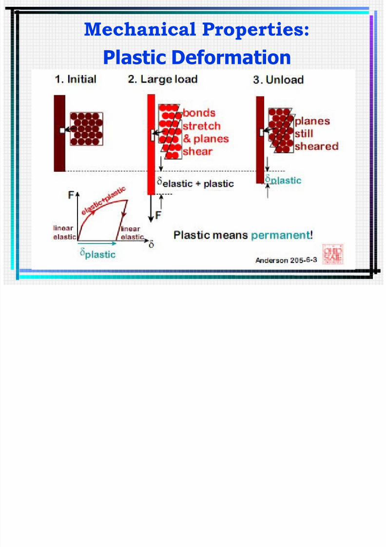
Mechanical Properties:
Plastic Deformation
Elongation After the unit of structure is cracked by tensile
force, the ratio of the total stretched length and the
origin length is called Percentage Elongation,
described by δ%
1)Definition: the ability of plastic deformation
but not destructing under external force.
2)Commonly used Index:
Percentage Elongation
Shrinkage of Sectional Area
Cold Bending Property
Mechanical Properties:
7/29/2019 03 Presentation Chapter 3 Material
http://slidepdf.com/reader/full/03-presentation-chapter-3-material 78/235
Mechanical Properties:
Plastic Deformation
h i l i

7/29/2019 03 Presentation Chapter 3 Material
http://slidepdf.com/reader/full/03-presentation-chapter-3-material 79/235
%100%10000
0
×
∆
=×
−
= l
l
l
l l k k
δ
lk — the gauge length after
cracking, mml0 — the origin gauge length,
mm△l
k
—the absolute length after
cracking, mm
Mechanical Properties:

7/29/2019 03 Presentation Chapter 3 Material
http://slidepdf.com/reader/full/03-presentation-chapter-3-material 80/235
The meaning of Percentage Elongation:i) The value of reflects the degree of the
plastic deformation before the material
cracks.ii) The larger , the better the plasticity of
material.
iii) Plastic material > 5%; Low carbon steel
= 20~30%
iv) Hard brittle material < 5%; Cast iron
= 1%
Mechanical Properties:
Mechanical Properties:

7/29/2019 03 Presentation Chapter 3 Material
http://slidepdf.com/reader/full/03-presentation-chapter-3-material 81/235
SHRINKAGE SECTION
After the unit of structure is cracked, the ratioof the reduced area of the cross-section and theoriginal (cross) sectional area is called Shrinkageof Sectional Area which is described by ψ%.
Fk —the minimum As after cracking ,mm2
F0 —original sectional area As , mm2
% F F F ψ θ
k θ 100×
−=
Mechanical Properties:
Mechanical Properties:

7/29/2019 03 Presentation Chapter 3 Material
http://slidepdf.com/reader/full/03-presentation-chapter-3-material 82/235
Cold Bending Property
Welding joint
R
The larger the , the better the plasticity
of the material.The of Low Carbon Steel is about 60%.
With R increasing, the plasticity of materials will be better and better.
Mechanical Properties:
M h i l P ti

7/29/2019 03 Presentation Chapter 3 Material
http://slidepdf.com/reader/full/03-presentation-chapter-3-material 83/235
i) Forming handling(process) and welding ease,such as bending and rolling 、 forging press
cold impacting 、 welding and etc.ii) Make the unit of structure to avoid cracking
for deformation after bearing load.
iii) The Pressure Vessels and their spare partsshould have the characteristic.
Mechanical Properties:The real meaning of the Plastic Index:

7/29/2019 03 Presentation Chapter 3 Material
http://slidepdf.com/reader/full/03-presentation-chapter-3-material 84/235
Mechanical Properties:
HardnessI. Definition: when something which is
harder than material itself is pressed on the surfaceof it, it will resist the pressure by deformation or bedamaged, such abilities are called Hardness.
I. The Hardness Index:
Brinell Hardness (HB)
Rochwell Hardness (HR)
Vickers Hardness (HV)
Mechanical Properties:

7/29/2019 03 Presentation Chapter 3 Material
http://slidepdf.com/reader/full/03-presentation-chapter-3-material 85/235
Mechanical Properties:
The test of HB:
d
D
P
)( )(
222 aMP
d D D D
p
F
p HB
−−
==
π
p ——Pressure, N
D——The diameter of
the rigid ball, mm
d ——The diameter of the indent, mm
F ——The area of the Indent, mm2
Mechanical Properties:

7/29/2019 03 Presentation Chapter 3 Material
http://slidepdf.com/reader/full/03-presentation-chapter-3-material 86/235
Generally, good Hardness leads to good
Strength and good resistance to wear and tear.
Experimental Value (MPa):
Low Carbon Steel HB
High Carbon Steel HB
Gray Cast Iron HB
I. Application of Hardness in Engineering
Mechanical Properties:The relationship of Hardness and Strength:

7/29/2019 03 Presentation Chapter 3 Material
http://slidepdf.com/reader/full/03-presentation-chapter-3-material 87/235
Mechanical Properties:
Impact toughness ak
Definition:
The ability of materials to resist the impact
load, i.e., the ability of materials that will makeplastic deformation immediately and rapidlywhen suddenly attacked by dynamic loading.

7/29/2019 03 Presentation Chapter 3 Material
http://slidepdf.com/reader/full/03-presentation-chapter-3-material 88/235
88

7/29/2019 03 Presentation Chapter 3 Material
http://slidepdf.com/reader/full/03-presentation-chapter-3-material 89/235
Mechanical Properties:
Impact Toughness
Mechanical Properties:

7/29/2019 03 Presentation Chapter 3 Material
http://slidepdf.com/reader/full/03-presentation-chapter-3-material 90/235
p
The larger is a k , the better is the ability of
materials to resist the impact load.
For Mediate and Low Pressure Vessels,a k ≥30 35J/cm2 , commonly a k 60 J/cm2.
The relationship between Toughness andPlasticity:
Generally, stronger toughness makes strongerplasticity; but strong plasticity may not make strong
toughness .
Hard Brittle Materials’ a k
Plastic Materials’ a k
PLASTIC (PERMANENT) DEFORMATION

7/29/2019 03 Presentation Chapter 3 Material
http://slidepdf.com/reader/full/03-presentation-chapter-3-material 91/235
PLASTIC (PERMANENT) DEFORMATION(at lower temperatures: T < T /3)
91
Physical Properties:

7/29/2019 03 Presentation Chapter 3 Material
http://slidepdf.com/reader/full/03-presentation-chapter-3-material 92/235
a. Modulus of elasticity (E)
(M Pa)ζ σ
=
E
Nature of E:1) It’s the index of materials’ ability to resist
elastic deformation. E↑ , ability to resist
deformation↑. E of steel is about 2.105
M Pa .
2) For the same material, T ↑ , E↓ .
Physical Properties:
Physical Properties:

7/29/2019 03 Presentation Chapter 3 Material
http://slidepdf.com/reader/full/03-presentation-chapter-3-material 93/235
b. Poisson’s Ratio
ζ
ζ µ
'=
(For steel: 0.3)
′ —— transverse stress
—— longitudinal stress
Physical Properties:
Physical Properties:

7/29/2019 03 Presentation Chapter 3 Material
http://slidepdf.com/reader/full/03-presentation-chapter-3-material 94/235
c. Thermal Expansion Coefficient ( )
•Physical Meaning of :
When T increases by 1 , the increasing℃
length per unit length is called Thermal
Expansion Coefficient.•Application of in Engineering.
)C/1( °==∆
∆∆∆
t l
l t l l α α
Physical Properties:
Chemical Properties:

7/29/2019 03 Presentation Chapter 3 Material
http://slidepdf.com/reader/full/03-presentation-chapter-3-material 95/235
Chemical Properties:
Definition: It’s the chemical stability of materials in medium, i.e. , it’s the nature that
whether the materials react with medium
chemically or electro-chemically leading tocorrosion.
Two index:
• Corrosion Resistance• Resistance to Oxidation
Chemical Properties:

7/29/2019 03 Presentation Chapter 3 Material
http://slidepdf.com/reader/full/03-presentation-chapter-3-material 96/235
a. Corrosion resistancethe ability of metal materials to resist the corrosioncaused by the medium (such as atmosphere, watervapor, electrolyte).
b. Oxidation resistance
1 ) Resist to high temperature oxidation;
2 ) Resist to oxide etch by other gaseousmedium, such as water vapor, CO2 , SO2 , etc.
Chemical Properties:

7/29/2019 03 Presentation Chapter 3 Material
http://slidepdf.com/reader/full/03-presentation-chapter-3-material 97/235
Manufacturing Properties
A. Definition: Proterties ( mechanical, physical &chemical) are technical / processing properties of material.
B.Classification:
Casting
Forging
Welding
Machining
Heat treatment
Cold – Warm forming
M f t i P ti

7/29/2019 03 Presentation Chapter 3 Material
http://slidepdf.com/reader/full/03-presentation-chapter-3-material 98/235
Casting Property : Fluidity, Congealing Shrinkage Rate
Forging Property : Resistance to Thermal Fragment,
Resistance to Oxidation, Thermo-plasticity.
Welding Property : Fluidity of parent material and
welding flux in the melting state, Congealing,Shrinkage Rate, Thermo-plasticity.
Machining Property : Hardness, Brittleness.
Heat Treatment Property : Heat Treatment Feasibility.
Cold & Warm forming Property: Plasticity, Toughness.
Manufacturing Properties
Classification and

7/29/2019 03 Presentation Chapter 3 Material
http://slidepdf.com/reader/full/03-presentation-chapter-3-material 99/235
1. According to the content of carbon (C%):
Low Carbon Steel
Medium Carbon Steel
High Carbon Steel
2.According to the smelting methods:
Full Killed Steel
Rimmed Steel
Semi-killed Steel
3.According to the quality:
Common Steel
High Grade Steel
Super High Grade Steel
designation of the equipments
A di t th t t f b (C%)

7/29/2019 03 Presentation Chapter 3 Material
http://slidepdf.com/reader/full/03-presentation-chapter-3-material 100/235
1. Low-carbon steel (C<0.25%) : Low strength and goodplasticity, used in chemical vessels in welding andmechanical units with low loads.
2. Medium Carbon Steel (C=0.25%~0.6%) : Medium
strength and plasticity, used as the important units of shaft,
gear, top cap of high pressure equipments and so on.
3. High Carbon Steel (C>0.6%) : High strength andhardness, poor plasticity, used as string, wire line and so on.
According to the content of carbon (C%)
According to the smelting methods

7/29/2019 03 Presentation Chapter 3 Material
http://slidepdf.com/reader/full/03-presentation-chapter-3-material 101/235
According to the smelting methodsFull Killed Steel:
deoxidized with a strong deoxidizing agent(silicon or aluminum)
to reduce the oxygen content during solidification of the moltensteel in the ingot.
Rimmed Steel ( boiled steel): A low-carbon steel containing sufficient iron oxide to give acontinuous evolution of carbon monoxide while the ingot is
solidifying, resulting in a case or rim of metal virtually free of voids. Sheet and strip products made from rimmed steel ingotshave very good surface quality.
Semi-killed Steel: A commonly used grade of steel manufactured for low carbon
bars and structural. A steel is considered semi killed so that it isincompletely deoxidized and it contains sufficient dissolvedoxygen to react with the carbon to form carbon monoxide tooffset st in the ingot.

7/29/2019 03 Presentation Chapter 3 Material
http://slidepdf.com/reader/full/03-presentation-chapter-3-material 102/235

7/29/2019 03 Presentation Chapter 3 Material
http://slidepdf.com/reader/full/03-presentation-chapter-3-material 103/235
What happens during rapid cooling?
• Phase diagrams only show stable phases that are formed
during slow cooling
• If cooling is rapid, the phase diagram becomes
invalid and metastable phases may form
• In the case of steel, the formation of ferrite and cementite
requires the diffusion of carbon out of the ferrite phase. What
happens if cooling is too rapid to allow this?
The crystal lattice tries to switch from fcc
(austenite) to bcc (ferrite). Excess carbon ->distorted body-centred lattice MARTENSITE
Martensite (α’)

7/29/2019 03 Presentation Chapter 3 Material
http://slidepdf.com/reader/full/03-presentation-chapter-3-material 104/235
Martensite (α )
• Distorted bcc lattice
• Non-equilibrium carbon content
• Forms plate-like or needle-shaped
grains
Fe, C 2, Mn 0.7 (wt%)

7/29/2019 03 Presentation Chapter 3 Material
http://slidepdf.com/reader/full/03-presentation-chapter-3-material 105/235
P d i h d d t d t l

7/29/2019 03 Presentation Chapter 3 Material
http://slidepdf.com/reader/full/03-presentation-chapter-3-material 106/235
Producing quenched and tempered steels
• Critical cooling rate for martensite formation depends on
concentration of alloying elements (e.g. C, Mn, Cr, Ni). Alloying elementsdelay the formation of ferrite and pearlite -> increase chances for
martensite formation
• Critical cooling rate defines concept of HARDENABILITY (i.e. ease of
martensite formation)
• Component thickness is an important parameter
Medium carbon steels generally used in quenched and tempered
condition, high-carbon steels almost always.
Applications: chisels, hammers, drills, cutting tools, springs...
□ Quenching and tempering not possible for low carbon steels ->
microstructure = ferrite + pearlite
Applications: car panels, bridges, pipes.

7/29/2019 03 Presentation Chapter 3 Material
http://slidepdf.com/reader/full/03-presentation-chapter-3-material 107/235
Corrosion
2.3. Corrosion & Protection of Chemical

7/29/2019 03 Presentation Chapter 3 Material
http://slidepdf.com/reader/full/03-presentation-chapter-3-material 108/235
2.3. Corrosion & Protection of ChemicalEquipments
Harm of corrosion
Chemical Corrosion
Electrochemical Corrosion
Inter-crystalline corrosion
Stress corrosion
Ha m of co osion

7/29/2019 03 Presentation Chapter 3 Material
http://slidepdf.com/reader/full/03-presentation-chapter-3-material 109/235
ht F
p p 210 /mg K ⋅
−
=
ht
m2F
p1
p0
K
g
g
g/cm2·h
Time of corrosion action —
Contact Area of corrosivemedia and test piece —
WT after corrosion —
WT before corrosion —
Corrosion Rate —
1.weight changing:
Harm of corrosion
Harm of corrosion

7/29/2019 03 Presentation Chapter 3 Material
http://slidepdf.com/reader/full/03-presentation-chapter-3-material 110/235
2.corrosion degree:
K a —Thickness variation per year mm/year
—Metallic density g/cm3
hF
γ
P V and h F V =⋅= _ _
γ ⋅
∆=∆∴ F
ph
Harm of corrosion
Harm of corrosion
7/29/2019 03 Presentation Chapter 3 Material
http://slidepdf.com/reader/full/03-presentation-chapter-3-material 111/235
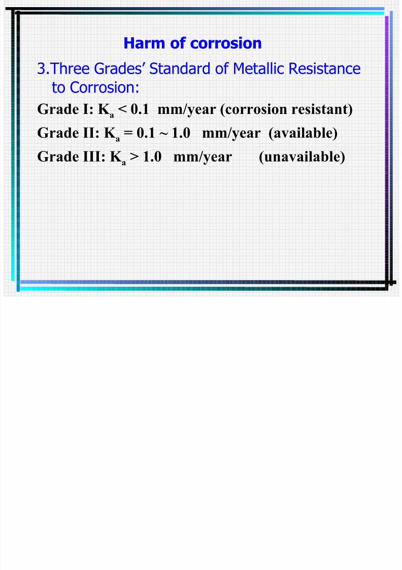
Harm of corrosion
3.Three Grades’ Standard of Metallic Resistanceto Corrosion:
Grade I: K a < 0.1 mm/year (corrosion resistant)
Grade II: K a = 0.1 ~ 1.0 mm/year (available)
Grade III: K a > 1.0 mm/year (unavailable)
Types of metallic corrosion

7/29/2019 03 Presentation Chapter 3 Material
http://slidepdf.com/reader/full/03-presentation-chapter-3-material 112/235
1.Uniform (General) Corrosion: i. Corrosion is over the whole metallic
surface
ii. Effect and danger are small
iii. Remaining enough corrosion allowance in
designation can still assure the strength
and expected life of equipments
Types of metallic corrosion
7/29/2019 03 Presentation Chapter 3 Material
http://slidepdf.com/reader/full/03-presentation-chapter-3-material 113/235
2.Local Corrosion:
i. Corrosion is at the local region in metals
ii. Very dangerousiii. Remaining the corrosion allowance in
designation has no effect.
2 Local Corrosion:

7/29/2019 03 Presentation Chapter 3 Material
http://slidepdf.com/reader/full/03-presentation-chapter-3-material 114/235
iv. Categories of Local Corrosion
(1)Seam Corrosion
(2)Pitting Corrosion
For example:
the pitting corrosion of Cr-Ni stainless
steel in the media containing [Cl- ]
2.Local Corrosion:
2 Local Corrosion:
7/29/2019 03 Presentation Chapter 3 Material
http://slidepdf.com/reader/full/03-presentation-chapter-3-material 115/235
(3)Stress Corrosion
(4)Inter-crystalline Corrosion
For example:the inter-crystalline corrosion of
Cr-Ni stainless steel under certain conditions
2.Local Corrosion:
Chemical Corrosion

7/29/2019 03 Presentation Chapter 3 Material
http://slidepdf.com/reader/full/03-presentation-chapter-3-material 116/235
1.Definition: The corrosion caused by chemical reactions
between metals and drying gas or non-electrolytesolution is called Chemical Corrosion.
Chemical Corrosion
Chemical Corrosion

7/29/2019 03 Presentation Chapter 3 Material
http://slidepdf.com/reader/full/03-presentation-chapter-3-material 117/235
2.Characteristics: i. Corrosion products are on the metallicsurface
ii. No electric current in the cause of corrosion
iii. The two natures of the products from
chemical reactions:
(1)Stability —— Passivation
(2)Unstability —— Activation
Chemical Corrosion
Chemical Corrosion

7/29/2019 03 Presentation Chapter 3 Material
http://slidepdf.com/reader/full/03-presentation-chapter-3-material 118/235
i. Metallic high temperature oxidation
(1)Oxidation resistance:
oxidized rapidly at high T
forming oxidation film
stopping oxidation
Chemical Corrosion
Chemical Corrosion

7/29/2019 03 Presentation Chapter 3 Material
http://slidepdf.com/reader/full/03-presentation-chapter-3-material 119/235
(2)High temperature oxidation of carbon steel and cast iron:
Stable
Unstable
Stablelayer I: Fe2O3
layer II: Fe3O4
layer III: FeO
T > 570 oxidation layer forms℃
inner layer Fe3O4 outer layer Fe2O3
T < 570 oxidation layer forms℃
T > 300 oxidation surface appears℃
Chemical Corrosion
Fe2O3

7/29/2019 03 Presentation Chapter 3 Material
http://slidepdf.com/reader/full/03-presentation-chapter-3-material 120/235
T < 570 ℃ T > 570℃
2 3
Fe3O4
FeO
Fe
Composition of ironic oxidation layer
Chemical Corrosion

7/29/2019 03 Presentation Chapter 3 Material
http://slidepdf.com/reader/full/03-presentation-chapter-3-material 121/235
(3)Solutions:
Adding some Cr Si Al to form stable
oxidation film of Cr2
O3
SiO2
Al2
O3
which
can prohibit the oxidation reaction from
proceeding.
Chemical Corrosion
Chemical Corrosion

7/29/2019 03 Presentation Chapter 3 Material
http://slidepdf.com/reader/full/03-presentation-chapter-3-material 122/235
ii. High temperature decarburization(1) T > 700 ℃
oxidation and decarburization both exist
Fe3C + O2 3Fe + CO2
Fe3C + CO2 3Fe + 2CO
Fe3C + H2O 3Fe + CO + H2
Chemical Corrosion
Chemical Corrosion

7/29/2019 03 Presentation Chapter 3 Material
http://slidepdf.com/reader/full/03-presentation-chapter-3-material 123/235
(2)Result
*Cementite Ferrite
with Strength, hardness and Fatigue
Strength all decreasing.
*Forming the air bubble which is the crack
initiation point.
(3)PreventionAdding Al or W
Chemical Corrosion
Chemical Corrosion

7/29/2019 03 Presentation Chapter 3 Material
http://slidepdf.com/reader/full/03-presentation-chapter-3-material 124/235
iii. Hydrogen corrosion (hydrogen brittleness)At relevant low temperature and pressure
(T≤200 ,℃ P ≤5MPa), H2 won’t
corrode the carbon and alloy steelsapparently.
At high T and P, the corrosion actions of
H2 to steels are obvious.
Chemical Corrosion
Chemical Corrosion

7/29/2019 03 Presentation Chapter 3 Material
http://slidepdf.com/reader/full/03-presentation-chapter-3-material 125/235
Mechanism of hydrogen corrosion:
Stage I —— “Hydrogen brittleness stage”
H disperses inward and dissolves.
Stage II —— “Hydrogen attack stage”
Chemical reaction vary the
structure of steels:
Fe3C + 2H2 3Fe + CH4
Chemical Corrosion
Electrochemical Corrosion

7/29/2019 03 Presentation Chapter 3 Material
http://slidepdf.com/reader/full/03-presentation-chapter-3-material 126/235
1.Definition: The corrosion caused by electrochemicalreactions between metals and electrolytes iscalled Chemical Corrosion.
Electrochemical Corrosion
Electrochemical Corrosion

7/29/2019 03 Presentation Chapter 3 Material
http://slidepdf.com/reader/full/03-presentation-chapter-3-material 127/235
2.Mechanism: Anode reaction —— Me Me+ + e
Electron movement —— eanode ecathode
Cathode reaction —— D + ecathode [D e]
Electrochemical Corrosion
Electrochemical Corrosion

7/29/2019 03 Presentation Chapter 3 Material
http://slidepdf.com/reader/full/03-presentation-chapter-3-material 128/235
3.Conditions of electrochemical
corrosion:•There is potential difference on the parts of metallicsurface or between different metals.
•The parts which have potential difference are connectedwith each other or the anode is connected with cathode.
•The metal with potential difference is in the electrolyteor the electrolyte where the anode and cathode areconnected with each other.
Electrochemical Corrosion
Inter-crystalline corrosion

7/29/2019 03 Presentation Chapter 3 Material
http://slidepdf.com/reader/full/03-presentation-chapter-3-material 129/235
Definition
It is the phenomenon that the corrosion occurs between two crystalline surfaces and causes the
grain boundary continuously damaged. Nature
It’s a kind of local and selective corrosive damage.
Inter crystalline corrosion
Inter-crystalline corrosion

7/29/2019 03 Presentation Chapter 3 Material
http://slidepdf.com/reader/full/03-presentation-chapter-3-material 130/235
Occurring in
Austenitic stainless steels
ReasonLack of Cr element in the grain boundaryAustenitic stainless steels (C<0.14%)
*At high temperature (1050ºC) C distributes completely in whole alloy.
Inter crystalline corrosion
*Between 400~850℃
C + Cr + Fe (Cr Fe) C

7/29/2019 03 Presentation Chapter 3 Material
http://slidepdf.com/reader/full/03-presentation-chapter-3-material 131/235
C + Cr + Fe (Cr . Fe)23C6
Anode
Cr 12.5%
Inter-crystallineCorrosion occurs
Separate out along the grain boundary Cr%
Cr lacking
Corrodingminicell
Cathode — Grain
— Cr lacking
region
Grain
(Cr . Fe)23C6
Cr lacking region
Grainboundary
Stress corrosion

7/29/2019 03 Presentation Chapter 3 Material
http://slidepdf.com/reader/full/03-presentation-chapter-3-material 132/235
i. Definition
The destruction is caused by both corrosive
media and the tensile stress action, this kind of damage is called Stress Corrosion.
Stress corrosion
Stress corrosion
7/29/2019 03 Presentation Chapter 3 Material
http://slidepdf.com/reader/full/03-presentation-chapter-3-material 133/235
ii. Initiation Circumstances
Carbon steel and various kinds of Alloy steel (suchas austenitic stainless steel) are in the media listed asfollowing:
(1)High concentrated chloride solution above
80℃
(2)High temperature and pressure water at
150~300 ℃(3)High temperature and concentrated caustic
solution
Stress corrosion
Stress corrosion

7/29/2019 03 Presentation Chapter 3 Material
http://slidepdf.com/reader/full/03-presentation-chapter-3-material 134/235
iii. Mechanism
Stage I: Breeding stage
The primary destruction (mechanical crack) is
formed in metallic surface under the co-actionof corrosion and tensile stress.
Stress corrosion
Stress corrosion

7/29/2019 03 Presentation Chapter 3 Material
http://slidepdf.com/reader/full/03-presentation-chapter-3-material 135/235
Stage II: Corrosion crack’s extension stage
Corrosive media dissolve the passivation film inthe cracks to form anode with the film becoming
cathode, the electrochemical corrosion thereforeoccurs.
The crack extents rapidly under the co-action of this corrosion and tensile stress.
Stress corrosion
Stress corrosion

7/29/2019 03 Presentation Chapter 3 Material
http://slidepdf.com/reader/full/03-presentation-chapter-3-material 136/235
Stage III: Breaking stage
St ess co os o
Stress corrosion
7/29/2019 03 Presentation Chapter 3 Material
http://slidepdf.com/reader/full/03-presentation-chapter-3-material 137/235
iv. Prevention measure
(1)Decrease or clear up the stress concentration
(2)Select the stress corrosion resistant materials:
Two-phase stainless steel ——
austenite + small amount (about 5%) of Ferrite
such as: 1Cr18Mn10Ni5Mo3N
0Cr17Mn13Mo2N 0Cr21Ni5Ti

7/29/2019 03 Presentation Chapter 3 Material
http://slidepdf.com/reader/full/03-presentation-chapter-3-material 138/235
Mechanism of cathodic protection:
The protected metallic devises are
polarized into cathodes by the direct current
(DC) from outer electrical power supply
taking the auxiliary electrode as the anode.
When the potential of cathode < that
of anode, the corrosion will be prohibited.

7/29/2019 03 Presentation Chapter 3 Material
http://slidepdf.com/reader/full/03-presentation-chapter-3-material 139/235
Corrosion Resistant Measures in MetallicEquipments

7/29/2019 03 Presentation Chapter 3 Material
http://slidepdf.com/reader/full/03-presentation-chapter-3-material 140/235
1.Selecting materials reasonably 2.Adding the lined protection
Equipments

7/29/2019 03 Presentation Chapter 3 Material
http://slidepdf.com/reader/full/03-presentation-chapter-3-material 141/235
Adding the lined protection
i. Metallic lining: stainless steel,
other metals(Cu Al Ti Cr Ni)ii. Nonmetallic lining: plastics,
rubbers, enamelware, etc.
+-

7/29/2019 03 Presentation Chapter 3 Material
http://slidepdf.com/reader/full/03-presentation-chapter-3-material 142/235
iii. Coating
iv. Adding corrosion
buffering agents
v. Electrochemical
protection
such as:
cathodic protectionCathodic Protection
Apparatuses
Heat Treatmentfi i i f h

7/29/2019 03 Presentation Chapter 3 Material
http://slidepdf.com/reader/full/03-presentation-chapter-3-material 143/235
1.Definition of heat treatment
Heat treatment is the technical process or treatmentsto steels in solid state according to the scheduled
requirements like heating, keeping warm and cooling,
their aims are to vary the internal structure and gain the
desired properties.
2.Basic Theories of heat treatment:
•When the basic components of steels (Fe) is heated to a
certain degree, its lattice structure of steel will vary fromone form to another as the temperature.
•Ferrite (F) and Austenite (A) are both the solid solution of
Fe, so they have the lattice structure of iron.
Heat Treatment

7/29/2019 03 Presentation Chapter 3 Material
http://slidepdf.com/reader/full/03-presentation-chapter-3-material 144/235
3.Bring forward the problem:
Find out the method and path of altering the propertiesof steels
4.Purpose of heat treatment
Eliminating some shortages of steels
Improving some properties of steels
5.Advantages of heat treatment
Intensifying the metallic materials, fully developing
the potential of materials, lightening the mass of
equipments and guaranteeing the security and expected
life of equipments.

7/29/2019 03 Presentation Chapter 3 Material
http://slidepdf.com/reader/full/03-presentation-chapter-3-material 145/235
Cooling media and way of cooling

7/29/2019 03 Presentation Chapter 3 Material
http://slidepdf.com/reader/full/03-presentation-chapter-3-material 146/235
Cooling in furnaceCooling in still airCooling in oilCooling in waterCooling in brine
Cooling CapacityCooling Speed
Heat Treating Process of steels:

7/29/2019 03 Presentation Chapter 3 Material
http://slidepdf.com/reader/full/03-presentation-chapter-3-material 147/235
Annealing
Normalizing
Quenching
Tempering

7/29/2019 03 Presentation Chapter 3 Material
http://slidepdf.com/reader/full/03-presentation-chapter-3-material 148/235
Quench

7/29/2019 03 Presentation Chapter 3 Material
http://slidepdf.com/reader/full/03-presentation-chapter-3-material 149/235
(1)Process :
Heating the steel pieces to the quenching temperature, cool them quicklyin the quenching agents after the warm-keeping treatment, then theAustenite changes into the Matensite.
(2)Quenching Temperature
*Hypo-eutectoid Steel (C<0.8%) heating above the A3 line 30~50ºC*Hyper-eutectoid Steel (C>0.8%) heating above the A1 line 30~50ºC
(3)Quenching Agent
*Mineral Oil, Water, and Brine.
*Generally speaking: Carbon Steel, cooling in water and brine.
Alloy Steel, cooling in oil.
Quench

7/29/2019 03 Presentation Chapter 3 Material
http://slidepdf.com/reader/full/03-presentation-chapter-3-material 150/235
(4)Quenching Function
developing the hardness, strength and wear (abrasion) resistance.
*The emergency cooling in quenching is apt to make flaw inthe steel pieces, so the tempering is commonly needed to clear up
the stress after quenching.
*Quenching and Tempering are always combined to thetechnical process.
iii. Tempering
(1)P

7/29/2019 03 Presentation Chapter 3 Material
http://slidepdf.com/reader/full/03-presentation-chapter-3-material 151/235
(1)Process
Heat the steel pieces which are already quenched to the certaintemperature (T<Tcritical), cool them quickly in still air after the warm-keepingtreatment.
(2)Purpose
Reduce or clear up the internal stress of workpieces after quenching,stabilize the internal structure and gain the different mechanical properties.
(3)Types of Tempering *Tempering at low temperature
after quenching, tempering between 150~250ºC.
Function——reduces the internal stress and brittleness of quenchingsteels, and at the same time keeps the high hardness and high wear
resistance.Usage ——in spares of various tools and ball bearing after carburation.

7/29/2019 03 Presentation Chapter 3 Material
http://slidepdf.com/reader/full/03-presentation-chapter-3-material 152/235

7/29/2019 03 Presentation Chapter 3 Material
http://slidepdf.com/reader/full/03-presentation-chapter-3-material 153/235
Common used materials
Common carbon steel

7/29/2019 03 Presentation Chapter 3 Material
http://slidepdf.com/reader/full/03-presentation-chapter-3-material 154/235
Vietnamese StandardCode ItemsTCVN 3600-81 Roofing steel sheet. Galvanized, acid-pickled.TCVN3601-81 Roofing steel sheetTCVN 3779-83 Thin acid-pickled sheet steelsTCVN 3780-83 Tinplate. Size, dimensions
TCVN 3781-83 Zincplate steel sheet. Technical requirementsTCVN 6525-99 Hot-dip zinc-coated carbon steel sheetTCVN 471:2004 Coated metal products, used in internal and external
construction works. Technical propertiesTCVN 470:2005 Aluminium coated and hot dip galvanised steel strip
and sheets
TCVN 1765:75 Carbon steel
Common carbon steel

7/29/2019 03 Presentation Chapter 3 Material
http://slidepdf.com/reader/full/03-presentation-chapter-3-material 155/235
- TCVN 1765-75 : 3 groups A, B, C.
Group A : according to mechanical property
Symbol : CTXX
CT : means carbon steel
XX : ultimate tensile stress σ b (N/mm2)example : CT38
Group A
Giíi h¹n bÒn (σ b = 380N/mm2
)

7/29/2019 03 Presentation Chapter 3 Material
http://slidepdf.com/reader/full/03-presentation-chapter-3-material 156/235
Symbols of different Standards

7/29/2019 03 Presentation Chapter 3 Material
http://slidepdf.com/reader/full/03-presentation-chapter-3-material 157/235
TCVN GOCT GB UNS AISI/SAE JIS AFNOR DIN BSC45 45 45 G10450 1045 S45C X45 C45 06A4540Cr 40X 40Cr G51400 5140 SCr440 42C4 42C4 530A40OL100Cr2 X15 GCr15 G52986 42100 SUJ2 100C6 100C6 535A9920Cr13 20X13 2X13 S42000 420 SUS420J1 Z20C13 X20Cr13 420S2908Cr18Ni10
08X18H90
0Cr18Ni9 S30200 304 SUS304 Z7CN18.09 X15Cr-Ni18304S31
CD100 Y10 T10 T72301 W109 SK4 Y1-90 10 -210Cr12 X12 Cr12 T30403 D3 SKD1 Z200C12 C105W1 BD380Ư18Cr4V P18 W18Cr4V T12001 T1 SKH2 Z80WCV X210C12 BT1
----------- 18-04-01 S 18-0-1 ASTM
-----------CT34 CT2 A2 - 36 SS330 F3360 Fe360 Fe360GX28-48 C130 HT300 F12803 No40 FC300 FGL300 GG30 260GC50-2 B150 QT500-7 F33800 8055-06 FCD500 FGS500-7 GGG50 B500/7
Common carbon steelThe content of the harmful elements S & P can be a little more :

7/29/2019 03 Presentation Chapter 3 Material
http://slidepdf.com/reader/full/03-presentation-chapter-3-material 158/235
(S≤0.055%, P≤0.045%)
Carbon steel StandardDesignationsFrance: AFNORXC 68Germany: DIN 1.1231Sweden: SS 1770 , SS 1778United States: AMS 5115 , AMS 5115C , ASTM A29 , ASTM A510 , ASTM A576 ,
ASTM A682 , MIL SPEC MIL-S-11713 (2) , SAE J403 , SAE J412 , SAE J414 , UNS G10700
Element Weight %
c 0.65-0.75
Mn 0.60-0.90
p 0.04 (max)
s 0.05 (max)
Rimmed Carbon Steel Suitable under the condition of P≤0.6MPa, t=0~250ºC,

7/29/2019 03 Presentation Chapter 3 Material
http://slidepdf.com/reader/full/03-presentation-chapter-3-material 159/235
S≤12mm.
a clean surface low in carbon content. known as drawing quality steel.
the steel is partially deoxidized. Carbon content is less
than 0.25% and manganese content is less than 0.6%.
do not retain any significant percentage of highlyoxidizable elements such as Aluminum, silicon or
titanium.
especially where ease of forming and surface finish are
major considerations.
ideal for rolling, large number of applications, and is
adapted to cold-bending, cold-forming and cold header
applications.
High-quality carbon steel

7/29/2019 03 Presentation Chapter 3 Material
http://slidepdf.com/reader/full/03-presentation-chapter-3-material 160/235
– Content of S & P to be (S & P≤0.04%)
– Uniform texture, good surface quality, superiorproperties than Common Steels.
– The number in designation indicates the percentage of the average content of C=0.08% & C=0.2%
– Steels that commonly contain Mn (without indicatingMn), if Mn < 0,7%
– Steels that contain Mn=0.7~1.2% (indicating Mn)
Super high-quality carbon steel

7/29/2019 03 Presentation Chapter 3 Material
http://slidepdf.com/reader/full/03-presentation-chapter-3-material 161/235
p g q y
S & P≤0.03%
Both the texture and properties of this
kind of steels’ are superior to that of
High Grade Steel.
Stainless steels

7/29/2019 03 Presentation Chapter 3 Material
http://slidepdf.com/reader/full/03-presentation-chapter-3-material 162/235
• Definition: > 11 wt% Cr. Ni, Mn may also be present
• Cr -> adherent Cr 2O3 film -> protection against corrosion
and oxidation
• Most stainless steels are austenitic (alloying elements
stabilise γ phase down to room T)
• Austenitic stainless steel is non-magnetic -> useful as
quick test
• Ferritic and martensitic stainless steels also available ->
increases range of mechanical properties available for
specific applications (Corrosion resistance not as good as
for austenitic stainless steel)
Cast Iron

7/29/2019 03 Presentation Chapter 3 Material
http://slidepdf.com/reader/full/03-presentation-chapter-3-material 163/235
1.The chemical components of
commonly used cast iron:
95% Fe + (2.5% ~ 4%) C + ( ~1%) Purities2.Structure:
Pealite + Cementite + Ladeburite + Graphite
Cast Iron

7/29/2019 03 Presentation Chapter 3 Material
http://slidepdf.com/reader/full/03-presentation-chapter-3-material 164/235
High carbon content low melting point
Cast Iron

7/29/2019 03 Presentation Chapter 3 Material
http://slidepdf.com/reader/full/03-presentation-chapter-3-material 165/235
• Cheap
• can produce complex parts quickly and easily throughsand casting
• BUT brittle Two types:
• Grey iron: Fe + C (graphite)
Formation of graphite rather than cementite promotedthrough high C and Si content, slow solidification rate
• White iron: Fe + Fe3C
Properties and Characteristics
7/29/2019 03 Presentation Chapter 3 Material
http://slidepdf.com/reader/full/03-presentation-chapter-3-material 166/235
Excellent casting property
Good machinability
Good wear resistance
Excellent property to reduce vibration
Low plasticity and brittleness
Low tensile strength and high (ultimate)
compression strength

7/29/2019 03 Presentation Chapter 3 Material
http://slidepdf.com/reader/full/03-presentation-chapter-3-material 167/235
i. Gray cast iron

7/29/2019 03 Presentation Chapter 3 Material
http://slidepdf.com/reader/full/03-presentation-chapter-3-material 168/235
(1)Properties and characteristics
*C exists in the form of plate-like graphite
*Gray fracture
*Low mechanical properties
*Excellent corrosion resistance in H2SO4
and NaOH
Grey cast iron

7/29/2019 03 Presentation Chapter 3 Material
http://slidepdf.com/reader/full/03-presentation-chapter-3-material 169/235
• Among least expensive metallic materials
• High fluidity -> can cast complex shapes
• Graphite flakes -> high damping capacity and good machineability ->
used e.g. as base structure for machines and heavy equipment
• BUT brittle due to shape of graphite flakes -> nodular iron better
Fe, C 3.52, Si 3.26, Mn 0.47 (wt%)
Spherical graphite cast iron
(1)Properties and characteristics
*C i i f f i i

7/29/2019 03 Presentation Chapter 3 Material
http://slidepdf.com/reader/full/03-presentation-chapter-3-material 170/235
*C exists in the form of spherical graphite
*Have better strength and a certainplasticity and toughness, its overall
mechanical properties are close to
that of steels.*Better corrosion resistance than that of
Gray Cast Iron except when it is in theacid solution.
Ductile / Nodular cast iron

7/29/2019 03 Presentation Chapter 3 Material
http://slidepdf.com/reader/full/03-presentation-chapter-3-material 171/235
• Addition of Mg / Ce to grey iron -> graphite forms as spheres rather than flakes -> improved toughness
• Applications: valves, pump bodies, gears, crankshafts
Fe, C 3.2, Si 2.5, Mg 0.05 (wt%)
iii. High-silicon cast iron (G)

7/29/2019 03 Presentation Chapter 3 Material
http://slidepdf.com/reader/full/03-presentation-chapter-3-material 172/235
(1)Properties and characteristics *Adding amount of Si (14.5~18%) to improve thecorrosion resistance of the cast iron.
White cast iron

7/29/2019 03 Presentation Chapter 3 Material
http://slidepdf.com/reader/full/03-presentation-chapter-3-material 173/235
• Exceptionally hard, but brittle and almost impossible tomachine used in very few applications e.g. rollers in rolling
mills
• Used as intermediary in production of malleable iron: heat
treatment at 800-900°C causes decomposition of cementite ->
graphite clusters. Resulting microstructure and properties
similar to nodular iron. Typical applications: connecting
rods, transmission gears, pipe fittings, flanges

7/29/2019 03 Presentation Chapter 3 Material
http://slidepdf.com/reader/full/03-presentation-chapter-3-material 174/235
4.Properties and Designation of
commonly used cast iron:

7/29/2019 03 Presentation Chapter 3 Material
http://slidepdf.com/reader/full/03-presentation-chapter-3-material 175/235
Gray cast iron :
Spherical graphite cast iron:
High-silicon cast iron

7/29/2019 03 Presentation Chapter 3 Material
http://slidepdf.com/reader/full/03-presentation-chapter-3-material 176/235
Common Material used inChemical Equipments
Objectives

7/29/2019 03 Presentation Chapter 3 Material
http://slidepdf.com/reader/full/03-presentation-chapter-3-material 177/235
01/09/12
Select suitable material of construction
Specify design temperature and
pressureCalculate wall thickness
Material of Construction

7/29/2019 03 Presentation Chapter 3 Material
http://slidepdf.com/reader/full/03-presentation-chapter-3-material 178/235
01/09/12
Mechanical and physical propertiesCorrosion resistance
Ease of fabrication Availability in standard sizes
Cost
Material of Construction

7/29/2019 03 Presentation Chapter 3 Material
http://slidepdf.com/reader/full/03-presentation-chapter-3-material 179/235
01/09/12
Preliminary Selection
Selection Charts
Literature Previous experience
Advise from materials supplier
Advise from equipment manufacturer
Advise from consultants
Material of Construction

7/29/2019 03 Presentation Chapter 3 Material
http://slidepdf.com/reader/full/03-presentation-chapter-3-material 180/235
01/09/12
Final Selection
Based on economic analysis which
would include
Material cost
Maintenance cost
Commonly Used Materials

7/29/2019 03 Presentation Chapter 3 Material
http://slidepdf.com/reader/full/03-presentation-chapter-3-material 181/235
01/09/12
Commonly Used Materials
Metals
Polymers or PlasticsCeramic Materials
Metals

7/29/2019 03 Presentation Chapter 3 Material
http://slidepdf.com/reader/full/03-presentation-chapter-3-material 182/235
01/09/12
Carbon steels
Stainless steels
Specialty alloys
Carbon Steels

7/29/2019 03 Presentation Chapter 3 Material
http://slidepdf.com/reader/full/03-presentation-chapter-3-material 183/235
01/09/12
Most common engineering material
Advantages
InexpensiveGood tensile strength and ductility
Available in a wide range of
standard forms and sizesEasily worked and welded
Carbon Steels
Li it ti

7/29/2019 03 Presentation Chapter 3 Material
http://slidepdf.com/reader/full/03-presentation-chapter-3-material 184/235
01/09/12
Limitations• Corrosion resistance not good
• External surface need painting to prevent atmosphericcorrosion
Suitable for use with:
Most organic solvents
Steam, air, cooling water, boiler feed water
Concentrated sulfuric acid and caustic alkalies
Stainless Steels

7/29/2019 03 Presentation Chapter 3 Material
http://slidepdf.com/reader/full/03-presentation-chapter-3-material 185/235
01/09/12
Most frequently used corrosion resistantmaterials in the chemical industry
High chromium or high nickel-chromium
alloys of iron chromium content must be > 12%
Nickel added to improve weldability and
corrosion resistance in non-oxidizing env.
Stainless Steels

7/29/2019 03 Presentation Chapter 3 Material
http://slidepdf.com/reader/full/03-presentation-chapter-3-material 186/235
01/09/12
Main Types of Stainless Steel
Type 304 – 18% Cr & 8% Ni
Type 304L – low carbon version to
improve welding of thick plates Type 316 – Mo added to improve
corrosion resistance in reducing
conditions and at high temperature.
Stainless Steels
7/29/2019 03 Presentation Chapter 3 Material
http://slidepdf.com/reader/full/03-presentation-chapter-3-material 187/235
01/09/12
Limitations – Intergranular corrosion or weld
decay possible in reducing
environment
– Stress cracking can be caused by a
few ppm of chloride ions
Special Alloys

7/29/2019 03 Presentation Chapter 3 Material
http://slidepdf.com/reader/full/03-presentation-chapter-3-material 188/235
01/09/12
Monel – 67% Ni, 33% Cu
Better corrosion resistance than SS No stress-corrosion cracking in chloride
solutions Temp. up to 500oC
Inconel - 76% Ni, 15% Cr, 7% Fe
High temperature acidic service Temp. up to 900oC
Plastics
7/29/2019 03 Presentation Chapter 3 Material
http://slidepdf.com/reader/full/03-presentation-chapter-3-material 189/235
01/09/12
Provide corrosion resistance at low cost.
Main advantages:
Excellent resistance to weak mineral acidsTolerate small changes in pH, minor
impurities or oxygen content
Light weight, easy to fabricate and install
Plastics

7/29/2019 03 Presentation Chapter 3 Material
http://slidepdf.com/reader/full/03-presentation-chapter-3-material 190/235
01/09/12
Major Limitations:
• Moderate tempeature and pressure
applications (T < 100oC; P < 5 atm.)• Low mechanical strength
• Only fair resistance to solvents
Plastics

7/29/2019 03 Presentation Chapter 3 Material
http://slidepdf.com/reader/full/03-presentation-chapter-3-material 191/235
01/09/12
Main Classes:
1. Thermoplastic – can be reshaped
2. Thermosetting – cannot be remouldedThermoplastic
• Polyethylenes (low cost; T < 50oC)
• Polypropylene ( T up to 120oC)• Polyvinyl chloride ( T ≤ 60oC)
Plastics

7/29/2019 03 Presentation Chapter 3 Material
http://slidepdf.com/reader/full/03-presentation-chapter-3-material 192/235
01/09/12
Thermosetting
- good mechanical properties (T 95oC)
- good chemical resistance (except strong alkalies)
Examples:
• Phenolic resins –filled with carbon, graphite, silica
• Polyester resins – reinforced with glass or carbon fibre toimprove strength

7/29/2019 03 Presentation Chapter 3 Material
http://slidepdf.com/reader/full/03-presentation-chapter-3-material 193/235
Rubber Lining
Metal surface lined with rubber to provide;

7/29/2019 03 Presentation Chapter 3 Material
http://slidepdf.com/reader/full/03-presentation-chapter-3-material 194/235
01/09/12
Metal surface lined with rubber to provide; Cost effective solution for corrosion control and
abrasion resistance e.g. acid storage, steelpickling
Why rubber?
• Able to bond strongly to various surfaces
• Good combination of elasticity andtensile strength

7/29/2019 03 Presentation Chapter 3 Material
http://slidepdf.com/reader/full/03-presentation-chapter-3-material 195/235
1.4.2 Effect of Alloy Elements to theproperties of steels

7/29/2019 03 Presentation Chapter 3 Material
http://slidepdf.com/reader/full/03-presentation-chapter-3-material 196/235
1.Alloy elements:i. Definition
The elements that are added on
purpose to develop the structure and
characteristics of steels.
ii. Main alloy elements
Cr Ni Mn Si Al MoV Ti Cu B Nb W Re

7/29/2019 03 Presentation Chapter 3 Material
http://slidepdf.com/reader/full/03-presentation-chapter-3-material 197/235
2.Alloy Steel
Definition
Alloy steels are those steels thatcontain the alloy elements which develop theproperties of steels.
Characteristics of the main alloy
elements:

7/29/2019 03 Presentation Chapter 3 Material
http://slidepdf.com/reader/full/03-presentation-chapter-3-material 198/235
elements:
i. Cr (1)Cr>13%, corrosion resistancedramatically
(2)Strength, hardness, wear resistance,oxidation resistance and hardenability all
(3)Plasticity and toughness
(4)Adds strength at high temperature
ii. Ni
(1)Enlarge the range of corrosion resistance
of stainless steel especially improve the

7/29/2019 03 Presentation Chapter 3 Material
http://slidepdf.com/reader/full/03-presentation-chapter-3-material 199/235
of stainless steel, especially improve the
resistance to base.
(2)Broad the -phase region as to be the
element that form the austenite.
(3)Develop the strength as well as keepexcellent properties of plasticity and
toughness.
(4)Improves strength at high T
iii. Mn

7/29/2019 03 Presentation Chapter 3 Material
http://slidepdf.com/reader/full/03-presentation-chapter-3-material 200/235
(1)Develop the strength and impacttoughness at low temperature.
(2)Broad the -phase region.
(3) Counteracts sulfur brittleness.
(4)Increases hardenability.
iv. Si
(1)Develops strength and fatigue

7/29/2019 03 Presentation Chapter 3 Material
http://slidepdf.com/reader/full/03-presentation-chapter-3-material 201/235
(1)Develops strength and fatigue
durability at high temperature.(2)Improve heat resistance
(3)Resistant to the corrosion of such media
as H2S and so on.(4)If amount of Si is too much,
plasticity and impact toughness both
(5)Strengthens steel
(6)Increases hardenability
v. Mo

7/29/2019 03 Presentation Chapter 3 Material
http://slidepdf.com/reader/full/03-presentation-chapter-3-material 202/235
(1)Develop the resistance of stainlesssteels to the chloride anion Cl-.
(2)Enhances H corrosion resistance.
(3)Improve the heat resistance.
(4)Raises grain-coarsening temperature.(5)Mo<0.6%, plasticity .
(6)Counteracts tendency toward temper
brittleness.
vi. Al

7/29/2019 03 Presentation Chapter 3 Material
http://slidepdf.com/reader/full/03-presentation-chapter-3-material 203/235
(1)Restricts grain growth.(2)Develops the impact toughness.
(3)Resistant to the corrosion caused by H2S.
(4)Improves the oxidation and heat resistance.(5)Cheap, common substitute for Cr among
heat-resistant steels.
vii. Ti
(1)Restricts grain growth.

7/29/2019 03 Presentation Chapter 3 Material
http://slidepdf.com/reader/full/03-presentation-chapter-3-material 204/235
(2)Develops strength and toughness.(3)Improves the oxidation and heatresistance.
(4)Stablizes C to prevent the
“inter-crystalline corrosion”.
(5)Prevents formation of austenite in high
chromium steels; prevents localized
depletion of chromium in stainless steelduring long heating.
viii. V

7/29/2019 03 Presentation Chapter 3 Material
http://slidepdf.com/reader/full/03-presentation-chapter-3-material 205/235
(1)Developes high-temperature strength.
(2)Increases hardenability.
(3)Restricts grain growth.
(4)Keeps the strength and improve theplasticity.
(5)Resists tempering
AE S P H/WR IT CR OR HR FD GR H
Cr

7/29/2019 03 Presentation Chapter 3 Material
http://slidepdf.com/reader/full/03-presentation-chapter-3-material 206/235
Ni
Mn P
Si H2S
Mo Mo<0.6% HCl
Al H2S
Ti in-c
V
Re
AE——alloy element
S ——strength
P ——plasticity

7/29/2019 03 Presentation Chapter 3 Material
http://slidepdf.com/reader/full/03-presentation-chapter-3-material 207/235
P plasticity
H/WR ——hardness and wear resistanceIT ——impact toughness
CR ——corrosion resistance
OR ——oxidation resistance
HR ——heat resistanceFD ——fatigue durability
GR ——grain refining
H ——hardability
in-c ——inter-crystalline

7/29/2019 03 Presentation Chapter 3 Material
http://slidepdf.com/reader/full/03-presentation-chapter-3-material 208/235
1.Definition:They are the steels that are formed by adding a fewalloy elements at the basis of Common Low CarbonSteel.
Common Low Alloy Steel
2.Composition:

7/29/2019 03 Presentation Chapter 3 Material
http://slidepdf.com/reader/full/03-presentation-chapter-3-material 209/235
(1)C<0.2%(2)Alloy elements
*Mn 1~1.5%
*Si Cr Ti V Nb Ni Al… 0.015 ~ 0.6%
3.Structure: Ferrite + Pearlite
4.Properties and characteristics:
7/29/2019 03 Presentation Chapter 3 Material
http://slidepdf.com/reader/full/03-presentation-chapter-3-material 210/235
4.Properties and characteristics:
i. High strength and large yield ratio
ii. Excellent welding property
iii. Good resistance to the corrosion of
atmosphere
iv. Perfect properties at low temperature
5.Designation (GB1591-88)
(New Designation GB/T1591-94)

7/29/2019 03 Presentation Chapter 3 Material
http://slidepdf.com/reader/full/03-presentation-chapter-3-material 211/235
(New Designation GB/T1591 94)
16Mn 16MnR 16Mng 15MnV15MnVR
15MnVg 09Mn2V 18MnMoNbR
The number ahead is the percentage of theC content, such as 16Mn (C = 0.16%).
Indicate the main alloy elements, thenumber thereafter is the percentage of that

7/29/2019 03 Presentation Chapter 3 Material
http://slidepdf.com/reader/full/03-presentation-chapter-3-material 212/235
number thereafter is the percentage of thatelement. If it is less than 1.5%, it can beomitted.
Content of alloy elements:1.5 ~ 2.49% Sign as “2” 2.5 ~ 3.49%
Sign as “3” 3.5 ~ 4.49% Sign as “4”

7/29/2019 03 Presentation Chapter 3 Material
http://slidepdf.com/reader/full/03-presentation-chapter-3-material 213/235
Commonly-used Designation:

7/29/2019 03 Presentation Chapter 3 Material
http://slidepdf.com/reader/full/03-presentation-chapter-3-material 214/235
i. Boiler Steel20g 22g 12Mng 16Mng 15MnVg
14MnMoVg 18MnMoNbg
ii. Vessel SteelQ235-AR 20R 16MnR 15MnVR
09MnVR 18MnMoNbR

7/29/2019 03 Presentation Chapter 3 Material
http://slidepdf.com/reader/full/03-presentation-chapter-3-material 215/235
Stainless Steel and Corrosion(Acid) Resistant Steel

7/29/2019 03 Presentation Chapter 3 Material
http://slidepdf.com/reader/full/03-presentation-chapter-3-material 216/235
Acid Resistant steels are the kind of alloysteels which are resistant to the corrosion
caused by acid or strong caustic media.
As a rule, we called them both “StainlessSteel”.
Examples:
*Chromium Stainless Steel*Chromium-nickel Stainless Steel
( )
1.Chromium Stainless Steel:

7/29/2019 03 Presentation Chapter 3 Material
http://slidepdf.com/reader/full/03-presentation-chapter-3-material 217/235
i. Component
< 0.2% C + (13 ~ 28%) Cr + Fe
ii. ConstructionFerrite or Martensite
(no Austenite even at high temperature)

7/29/2019 03 Presentation Chapter 3 Material
http://slidepdf.com/reader/full/03-presentation-chapter-3-material 218/235
iv. Commonly-used Chromium Stainless Steel

7/29/2019 03 Presentation Chapter 3 Material
http://slidepdf.com/reader/full/03-presentation-chapter-3-material 219/235
1Cr13 2Cr13 0Cr13 0Cr17 0Cr17Tiv. Designation
(1)The first number:
Average C content Average with C
amount of 1000 points0 C < 0.1% 1: C≤0.15% 2: C≈0.2%
(2)The second number:
percentage of the average content of Cr
2.Chromium-nickel Stainless

7/29/2019 03 Presentation Chapter 3 Material
http://slidepdf.com/reader/full/03-presentation-chapter-3-material 220/235
Steel: i. Component
≤ 0.14% C + ( 17~19% ) Cr + ( 8 ~11%) Ni+ Fe
Briefly called “18 — 8” Steel
Typical Designation: 1Cr18Ni9Ti
ii. Construction
Single austenite structure at normaltemperature
iii. Characteristics

7/29/2019 03 Presentation Chapter 3 Material
http://slidepdf.com/reader/full/03-presentation-chapter-3-material 221/235
iii. Characteristics
(1)High strength and good plasticity
& toughness
(2)Large range of suitable temperature
-196 ~ 800℃ ℃(3)Excellent technical properties
(4)Good corrosion resistance
ΘNon-corrosive media:
cold phosphorus acid, nitric acid, acetic acid,
hydrogen sulfide, sulfate, nitride, base liquid,

7/29/2019 03 Presentation Chapter 3 Material
http://slidepdf.com/reader/full/03-presentation-chapter-3-material 222/235
hydrogen sulfide, sulfate, nitride, base liquid,
petroleum chemicals, etc.
ΘCorrosive media:
hydrochloric acid, dilute sulfuric acid (<10%),
hot phosphorus acid, oxalic acid ,melting caustic potassium, melting caustic
alkali, Cl-, bromine (Br), iodine (I), etc.
(5)Inter-crystalline corrosion easily occurs between400~800 ℃

7/29/2019 03 Presentation Chapter 3 Material
http://slidepdf.com/reader/full/03-presentation-chapter-3-material 223/235
Θ Definition of inter-crystalline corrosion:
It is the phenomenon that the corrosion occursbetween two crystalline surfaces and causes the grainboundary continuously damaged.
ΘNature:
It’s a kind of local and selective corrosive damage.
ΘOccurring in:

7/29/2019 03 Presentation Chapter 3 Material
http://slidepdf.com/reader/full/03-presentation-chapter-3-material 224/235
Austenitic stainless steelsΘReason:
Lack of Cr element in the grain boundary
ΘAustenitic stainless steels (C<0.14%):*At high temperature (1050ºC)
C distributes completely in whole alloy.
*Between 400~800℃
C + Cr + Fe (Cr . Fe)23C6
Separate out along the grain boundary

7/29/2019 03 Presentation Chapter 3 Material
http://slidepdf.com/reader/full/03-presentation-chapter-3-material 225/235
Anode
Cr 12.5%
Inter-crystallineCorrosion occurs
p g g y
Cr%
Cr lacking
Corroding minicell
Cathode — Grain
— Cr lacking
region
Grain
(Cr . Fe)23C6
Cr lacking region
Grainboundary
ΘDamage:
To be brittle, even softly beating can makes
it break into dust. Have very low strength.

7/29/2019 03 Presentation Chapter 3 Material
http://slidepdf.com/reader/full/03-presentation-chapter-3-material 226/235
it break into dust. Have very low strength.
ΘPreventive measures:
*Solution heat treatment ——
quenching again (1100~1150ºC) to
dissolve C and Cr into the austenite.*Reduce the content of C ——
preventing C to combine with Cr, then less
Cr will be separated out.
For example: 0Cr18Ni9 (C ≤ 0.08%)00Cr18Ni9 (C < 0.03%)
*C stabilization treatment ——

7/29/2019 03 Presentation Chapter 3 Material
http://slidepdf.com/reader/full/03-presentation-chapter-3-material 227/235
adding Ti or Nb to form TiC or NbC tostabilize C.
For example: 1Cr18Ni9Ti 1Cr19Ni11Nb
*Add microelement —— adding B can vary the nature of grainboundary to prevent (Cr . Fe)23C6 to be
separated out.
(6) Pitting corrosion occurs in the media
containing [Cl-]

7/29/2019 03 Presentation Chapter 3 Material
http://slidepdf.com/reader/full/03-presentation-chapter-3-material 228/235
ΘMechanism:[Cl-] intrudes into the flaw of passivation
film (Cr2 O3) and reacts with metallic ion to
form strong acidic salts ([M+
] + [Cl-
] → MCl)which can dissolve the passivation film ——
the locally corroded film becomes a “passive-
active” minicell —— with corrosion taking
place.
ΘDamage:
Fast corrosion speed easily perforates the

7/29/2019 03 Presentation Chapter 3 Material
http://slidepdf.com/reader/full/03-presentation-chapter-3-material 229/235
thin (only several mini-meter thick) stainlesssteel by corrosion.
ΘPreventive measures:
*Adding some alloy elementsThe most effective elements to improve the
pitting corrosion resistance: Cr, Mo
Secondarily effective elements: Ni, Si, N, Re
*Cr≥25%, pitting corrosion won’t occur.
2%Mo improve pitting corrosionresistance dramatically, Mo and [Cl-]

7/29/2019 03 Presentation Chapter 3 Material
http://slidepdf.com/reader/full/03-presentation-chapter-3-material 230/235
y, [ ]form the protective film (MoOCl2) which
can prevent the passivation film being
perforated.
*Materials resistant to the corrosion of [Cl-]:high Cr-Ni stainless steel containing Mo
such as: 1Cr18Ni12Mo2Ti
00Cr20Ni30Mo2Nb000Cr30Mo2
Heat-resisting Steel and Low-temperature Steel

7/29/2019 03 Presentation Chapter 3 Material
http://slidepdf.com/reader/full/03-presentation-chapter-3-material 231/235
1.Heat-resisting Steel:
i. Characteristics
(1)Excellent high-temperature oxidationresistance (excellent high-T chemical
stability)
(2)Good high-T mechanical properties
(strength at high T)
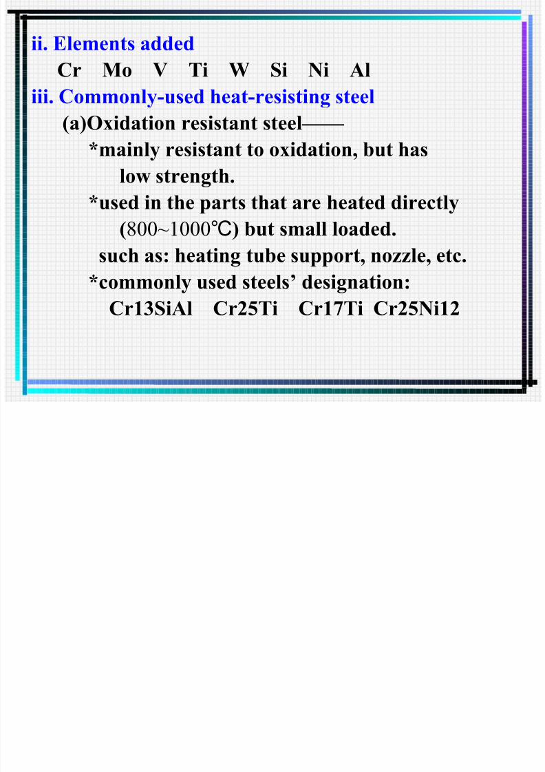
7/29/2019 03 Presentation Chapter 3 Material
http://slidepdf.com/reader/full/03-presentation-chapter-3-material 232/235
(b)Refractory steel
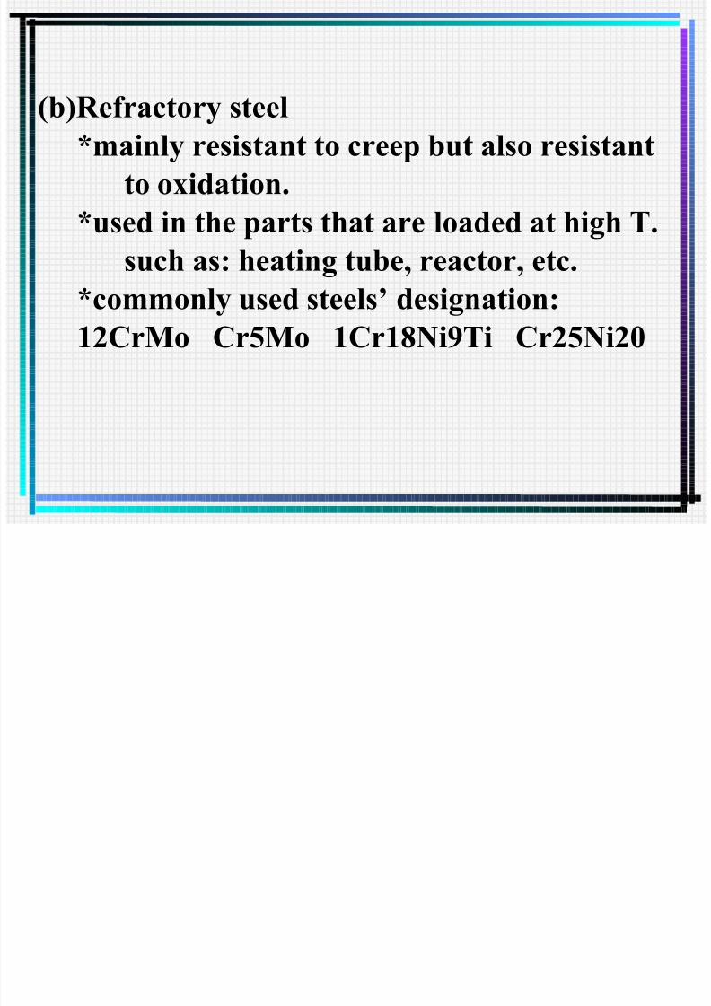
7/29/2019 03 Presentation Chapter 3 Material
http://slidepdf.com/reader/full/03-presentation-chapter-3-material 233/235
*mainly resistant to creep but also resistantto oxidation.
*used in the parts that are loaded at high T.
such as: heating tube, reactor, etc.
*commonly used steels’ designation:
12CrMo Cr5Mo 1Cr18Ni9Ti Cr25Ni20
2.Low-temperature Steel: i. Working temperature

7/29/2019 03 Presentation Chapter 3 Material
http://slidepdf.com/reader/full/03-presentation-chapter-3-material 234/235
< -20 Low temperature℃ -20 ~-40 Non-cryogenic temperature℃
< -40 Cryogenic temperature℃
ii. Characteristics
(1)Excellent low-temperature toughness
(2)Excellent processing workability and
weldability
iii. Requirements of structure
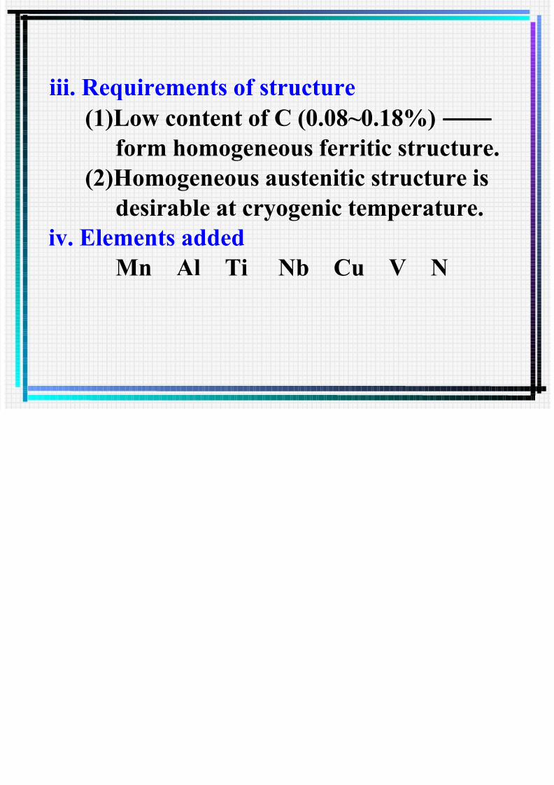
7/29/2019 03 Presentation Chapter 3 Material
http://slidepdf.com/reader/full/03-presentation-chapter-3-material 235/235
(1)Low content of C (0.08~0.18%) —— form homogeneous ferritic structure.
(2)Homogeneous austenitic structure is
desirable at cryogenic temperature.iv. Elements added
Mn Al Ti Nb Cu V N