Embed Size (px)
DESCRIPTION
manual
Citation preview
Signature Series Component Installation
Manual
P/N 270497 • Rev 2.1 • 16DEC04
DEVELOPED BY Edwards Systems Technology 8985 Town Center Parkway Bradenton, FL 34202 (941) 739-4300
COPYRIGHT NOTICE Copyright © 2004 Edwards Systems Technology
This manual and the products it describes are copyrighted by Edwards Systems Technology (EST). You may not reproduce, translate, transcribe, or transmit any part of this manual without express, written permission from EST.
This manual contains proprietary information intended for distribution to authorized persons or companies for the sole purpose of conducting business with Edwards Systems Technology, Inc. If you distribute any information contained in this manual to unauthorized persons, you have violated all distributor agreements and we may take legal action.
CREDITS This manual was designed and written by EST Technical Services - Documentation Department, Sarasota.

Signature Series Component Installation Manual i
Content
Audible Detector Base SIGA-270(L) - Fire Alarm Stations SIGA-270P - 2-Stage Fire Alarm Station SIGA-278 - Double Action Fire Alarm Station SIGA-AA30 and SIGA-AA50 - Audio Amplifiers SIGA-AB4 - Audible Detector Base SIGA-APS (-220) - Auxiliary Power Supply Module SIGA-CC1 - Single Input Signal Module SIGA-CC1S - Auto-Sync Output Module SIGA-CC2 - Dual Input Signal Module SIGA-CR - Control Relay Module SIGA-CRR - Polarity Reversal Relay SIGA-CT1 - Single Input Module SIGA-CT1I - Single Input Module SIGA-CT2 - Dual Input Module SIGA-CT2I - Dual Input Module SIGA-DG and SIGA-DGMF - Detector Guard with Optional Mounting Flange SIGA-DGS - Surface Adapter for use with the SIGA-DG Detector Guard SIGA-DGSA - Surface Adapter SIGA-DGSB - Detector Guard Surface Box SIGA-DH - Duct Detector Housing Assembly SIGA-DMP - Duct Detector Mounting Plate SIGA-DTS - Duct Detector Test Station SIGA-HFS - Intelligent Fixed-Temperature Heat Detector SIGA-HRS - Intelligent Fixed-Temperature Rate-of-Rise Heat Detector SIGA-HRSI - Intelligent Grade 1 Heat Detector SIGA-IB - Detector Base SIGA-IB4 - Detector Base SIGA-IM - Isolator Module SIGA-IO - Input-Output Module SIGA-IPHS(B) - Intelligent 4D Multisensor Smoke Detector SIGA-IPHSI - Intelligent 4D Multisensor Smoke Detector SIGA-IS - Intelligent Ionization Smoke Detector SIGA-ISI - Intelligent Ionization Smoke Detector SIGA-LED - Remote LED Alarm Indicator SIGA-MAB - Class A-B Input-Output Module SIGA-MB4 - Transponder Mounting Bracket SIGA-MCC1 - Single Input Signal Module SIGA-MCC1S - Auto-sync Output Module SIGA-MCC2 - Dual Input Signal Module SIGA-MCR - Control Relay SIGA-MCRR - Control Reversing Relay Module SIGA-MD(S) - Motion Detector SIGA-MDM - Signature Digital Message Module
ii Signature Series Component Installation Manual
SIGA-MIO - Input-Output Module SIGA-MM1 - Monitor Module SIGA-MP1 - Mounting Plate SIGA-MP2 - Mounting Plate SIGA-MP2L - Mounting Plate SIGA-MRM1 - Riser Monitor Module SIGA-PHS - Intelligent 3D Multisensor Smoke Detector SIGA-PHSI - Intelligent 3D Multisensor Smoke Detector SIGA-PS - Intelligent Photoelectric Smoke Detector SIGA-PSI - Intelligent Photoelectric Smoke Detector SIGA-RB - Detector Base SIGA-RB4 - Detector Base SIGA-RM1 - Riser Monitor Module SIGA-SB - Detector Base SIGA-SB4 - Detector Base SIGA-SEC2 - Security Loop Module SIGA-TS - 4 Inch Box Trim Skirt-Ring SIGA-TS4 - Trim Skirt-Ring SIGA-TSB - Four Inch Box Trim Skirt-Ring SIGA-UIO2R - Universal Input-Output Motherboard SIGA-UIO6(R) - Universal Input-Output Motherboard SIGA-UM - Universal Class A-B Module SIGA-WTM - Waterflow-Tamper Module SIGI-271 - Break Glass Station SIGI-IBS - Detector Base
Signature Series Component Installation Manual iii
Important Information
Limitation of liability The products described in this manual have been designed to meet the requirements of NFPA Standard 72; Underwriters Laboratories, Inc., Standard 864; and Underwriters Laboratories of Canada, Inc., Standard ULC S527. Installation in accordance with this manual, applicable codes, and the instructions of the authority having jurisdiction is mandatory. EST shall not under any circumstances be liable for any incidental or consequential damages arising from loss of property or other damages or losses owing to the failure of EST products beyond the cost of repair or replacement of any defective products. EST reserves the right to make product improvements and change product specifications at any time.
While every precaution has been taken during the preparation of this manual to ensure the accuracy of its contents, EST assumes no responsibility for errors or omissions.
FCC warning This equipment can generate and radiate radio frequency energy. If this equipment is not installed in accordance with this manual, it may cause interference to radio communications. This equipment has been tested and found to comply within the limits for Class A computing devices pursuant to Subpart B of Part 15 of the FCC Rules. These rules are designed to provide reasonable protection against such interference when this equipment is operated in a commercial environment. Operation of this equipment is likely to cause interference, in which case the user at his own expense, will be required to take whatever measures may be required to correct the interference.
iv Signature Series Component Installation Manual
Document history
Revision Date Reason For Change
1.0 12FEB97 Initial Release
2.0 06DEC99 Added the following installation sheets to the manual: AB4, CRR, MAB, MCR, MCRR, MCC1, MCC2, MCT2, UIO2, and UIO6(R). Removed SIGA-RB Sounder Base.
3.0 16DEC04 Added the following installation sheets: Audible Detector Base, SIGA-AA30 and SIGA-AA50, SIGA-AB4, SIGA-APS (-220), SIGA-CC1S, SIGA-CT1I, SIGA-CT2I, SIGA-DGSA, SIGA-DGSB, SIGA-IO, SIGA-IPHSI, SIGA-ISI, SIGA-MCC1S, SIGA-MD(S), SIGA-MDM, SIGA-MIO, SIGA-MRM1, SIGA-PHSI, SIGA-PSI, SIGA-RM1, SIGA-SEC2, SIGA-TS4, SIGA-TSB. Removed the following installation sheets: 2-CTM, SIGA-MCT2.
Installation Sheet 19NOV03 P/N: 3100672 REV: 2.0 Audible Detector Base 1 / 4
Audible Detector Base
Product description
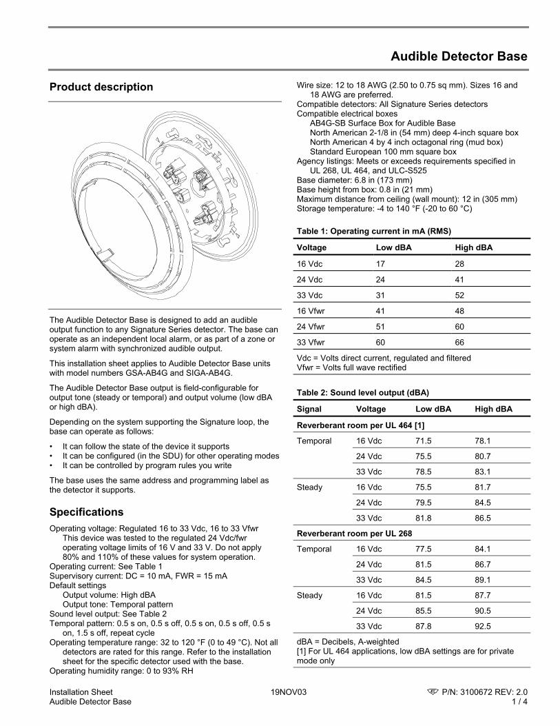
The Audible Detector Base is designed to add an audible output function to any Signature Series detector. The base can operate as an independent local alarm, or as part of a zone or system alarm with synchronized audible output.
This installation sheet applies to Audible Detector Base units with model numbers GSA-AB4G and SIGA-AB4G.
The Audible Detector Base output is field-configurable for output tone (steady or temporal) and output volume (low dBA or high dBA).
Depending on the system supporting the Signature loop, the base can operate as follows:
• It can follow the state of the device it supports • It can be configured (in the SDU) for other operating modes • It can be controlled by program rules you write
The base uses the same address and programming label as the detector it supports.
Specifications Operating voltage: Regulated 16 to 33 Vdc, 16 to 33 Vfwr
This device was tested to the regulated 24 Vdc/fwr operating voltage limits of 16 V and 33 V. Do not apply 80% and 110% of these values for system operation.
Operating current: See Table 1 Supervisory current: DC = 10 mA, FWR = 15 mA Default settings
Output volume: High dBA Output tone: Temporal pattern
Sound level output: See Table 2 Temporal pattern: 0.5 s on, 0.5 s off, 0.5 s on, 0.5 s off, 0.5 s
on, 1.5 s off, repeat cycle Operating temperature range: 32 to 120 °F (0 to 49 °C). Not all
detectors are rated for this range. Refer to the installation sheet for the specific detector used with the base.
Operating humidity range: 0 to 93% RH
Wire size: 12 to 18 AWG (2.50 to 0.75 sq mm). Sizes 16 and 18 AWG are preferred.
Compatible detectors: All Signature Series detectors Compatible electrical boxes
AB4G-SB Surface Box for Audible Base North American 2-1/8 in (54 mm) deep 4-inch square box North American 4 by 4 inch octagonal ring (mud box) Standard European 100 mm square box
Agency listings: Meets or exceeds requirements specified in UL 268, UL 464, and ULC-S525
Base diameter: 6.8 in (173 mm) Base height from box: 0.8 in (21 mm) Maximum distance from ceiling (wall mount): 12 in (305 mm) Storage temperature: -4 to 140 °F (-20 to 60 °C) Table 1: Operating current in mA (RMS)
Voltage Low dBA High dBA
16 Vdc 17 28
24 Vdc 24 41
33 Vdc 31 52
16 Vfwr 41 48
24 Vfwr 51 60
33 Vfwr 60 66
Vdc = Volts direct current, regulated and filtered Vfwr = Volts full wave rectified Table 2: Sound level output (dBA)
Signal Voltage Low dBA High dBA
Reverberant room per UL 464 [1]
Temporal 16 Vdc 71.5 78.1
24 Vdc 75.5 80.7
33 Vdc 78.5 83.1
Steady 16 Vdc 75.5 81.7
24 Vdc 79.5 84.5
33 Vdc 81.8 86.5
Reverberant room per UL 268
Temporal 16 Vdc 77.5 84.1
24 Vdc 81.5 86.7
33 Vdc 84.5 89.1
Steady 16 Vdc 81.5 87.7
24 Vdc 85.5 90.5
33 Vdc 87.8 92.5
dBA = Decibels, A-weighted [1] For UL 464 applications, low dBA settings are for private mode only
P/N: 3100672 REV: 2.0 19NOV03 Installation Sheet 2 / 4 Audible Detector Base
Installation instructions
Cautions
To avoid accidental damage to the panel, disconnect all power before wiring the unit.
Electrical supervision requires the wire run to be broken at each terminal. Do not loop the signaling circuit field wires around the terminals.
The base must be connected to a continuous voltage whether the output tone is set to steady or temporal.
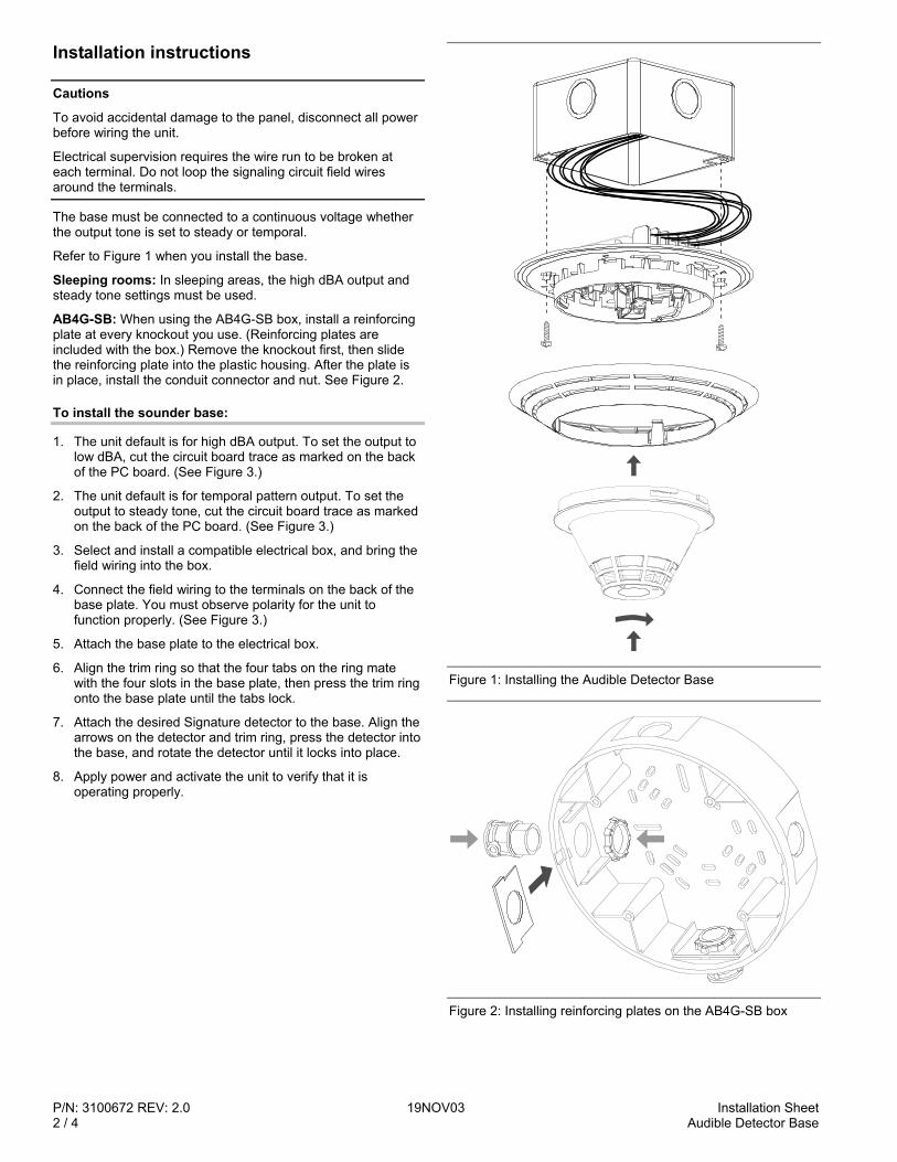
Refer to Figure 1 when you install the base.
Sleeping rooms: In sleeping areas, the high dBA output and steady tone settings must be used.
AB4G-SB: When using the AB4G-SB box, install a reinforcing plate at every knockout you use. (Reinforcing plates are included with the box.) Remove the knockout first, then slide the reinforcing plate into the plastic housing. After the plate is in place, install the conduit connector and nut. See Figure 2.
To install the sounder base:
1. The unit default is for high dBA output. To set the output to low dBA, cut the circuit board trace as marked on the back of the PC board. (See Figure 3.)
2. The unit default is for temporal pattern output. To set the output to steady tone, cut the circuit board trace as marked on the back of the PC board. (See Figure 3.)
3. Select and install a compatible electrical box, and bring the field wiring into the box.
4. Connect the field wiring to the terminals on the back of the base plate. You must observe polarity for the unit to function properly. (See Figure 3.)
5. Attach the base plate to the electrical box.
6. Align the trim ring so that the four tabs on the ring mate with the four slots in the base plate, then press the trim ring onto the base plate until the tabs lock.
7. Attach the desired Signature detector to the base. Align the arrows on the detector and trim ring, press the detector into the base, and rotate the detector until it locks into place.
8. Apply power and activate the unit to verify that it is operating properly.
Figure 1: Installing the Audible Detector Base
Figure 2: Installing reinforcing plates on the AB4G-SB box
Installation Sheet 19NOV03 P/N: 3100672 REV: 2.0 Audible Detector Base 3 / 4
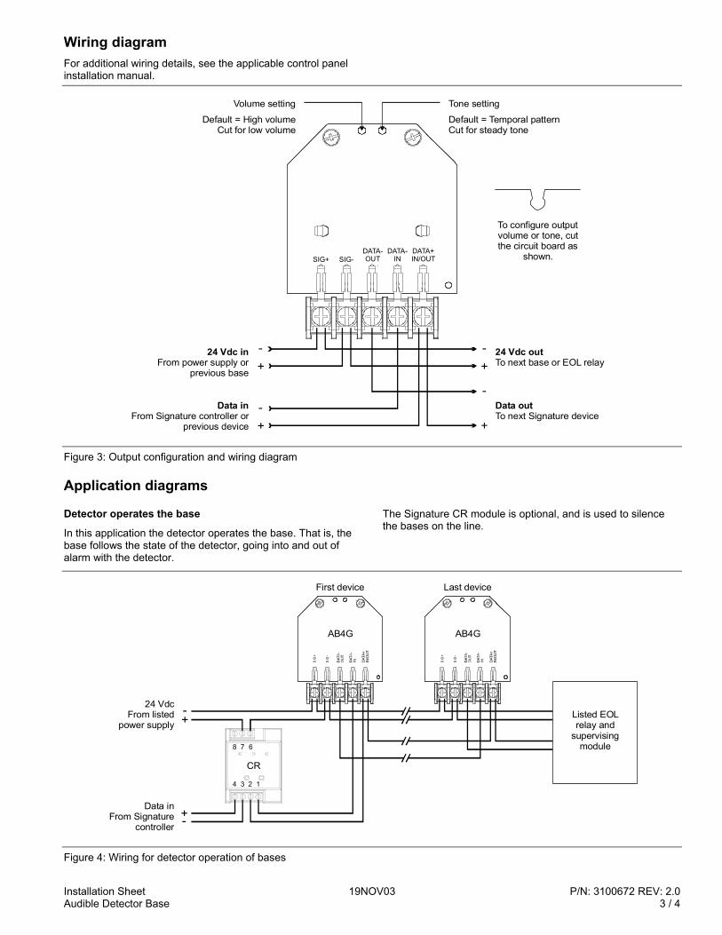
Wiring diagram For additional wiring details, see the applicable control panel installation manual.
SIG+ SIG-DATA-OUT
DATA-IN
DATA+IN/OUT
24 Vdc inFrom power supply or
previous base
Data inFrom Signature controller or
previous device
24 Vdc outTo next base or EOL relay
Data outTo next Signature device
+-
+
-
Volume setting
Default = High volumeCut for low volume
Tone setting
Default = Temporal patternCut for steady tone
+-
+-
To configure output volume or tone, cut the circuit board as
shown.
Figure 3: Output configuration and wiring diagram
Application diagrams
Detector operates the base
In this application the detector operates the base. That is, the base follows the state of the detector, going into and out of alarm with the detector.
The Signature CR module is optional, and is used to silence the bases on the line.
SIG
+
SIG
-
DAT
A+IN
/OU
T
AB4G
Data inFrom Signature
controller
-+
24 VdcFrom listed
power supply
+-
Listed EOL relay and
supervising module
SIG
+
SIG
-
DAT
A+IN
/OU
T
AB4G
First device Last device
CR
4 3 2 1
8 7 6
Figure 4: Wiring for detector operation of bases
P/N: 3100672 REV: 2.0 19NOV03 Installation Sheet 4 / 4 Audible Detector Base
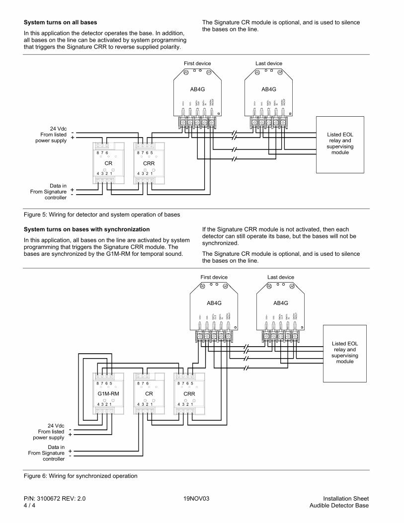
System turns on all bases
In this application the detector operates the base. In addition, all bases on the line can be activated by system programming that triggers the Signature CRR to reverse supplied polarity.
The Signature CR module is optional, and is used to silence the bases on the line.
SIG
+
SIG
-
DAT
A+IN
/OU
T
AB4G
Data inFrom Signature
controller
-+
24 VdcFrom listed
power supply
+-
Listed EOL relay and
supervising module
SIG
+
SIG
-
DAT
A+IN
/OU
T
AB4G
First device Last device
CR
4 3 2 1
8 7 6
CRR
4 3 2 1
8 7 6 5
Figure 5: Wiring for detector and system operation of bases
System turns on bases with synchronization
In this application, all bases on the line are activated by system programming that triggers the Signature CRR module. The bases are synchronized by the G1M-RM for temporal sound.
If the Signature CRR module is not activated, then each detector can still operate its base, but the bases will not be synchronized.
The Signature CR module is optional, and is used to silence the bases on the line.
Data inFrom Signature
controller
-+
24 VdcFrom listed
power supply
+-
SIG
+
SIG
-
DAT
A+IN
/OU
T
AB4G
Listed EOL relay and
supervising module
SIG
+
SIG
-
DAT
A+IN
/OU
T
AB4G
First device Last device
CR
8 7 6
4 3 2 1
G1M-RM
4 3 2 1
8 7 6 5
CRR
4 3 2 1
8 7 6 5
Figure 6: Wiring for synchronized operation
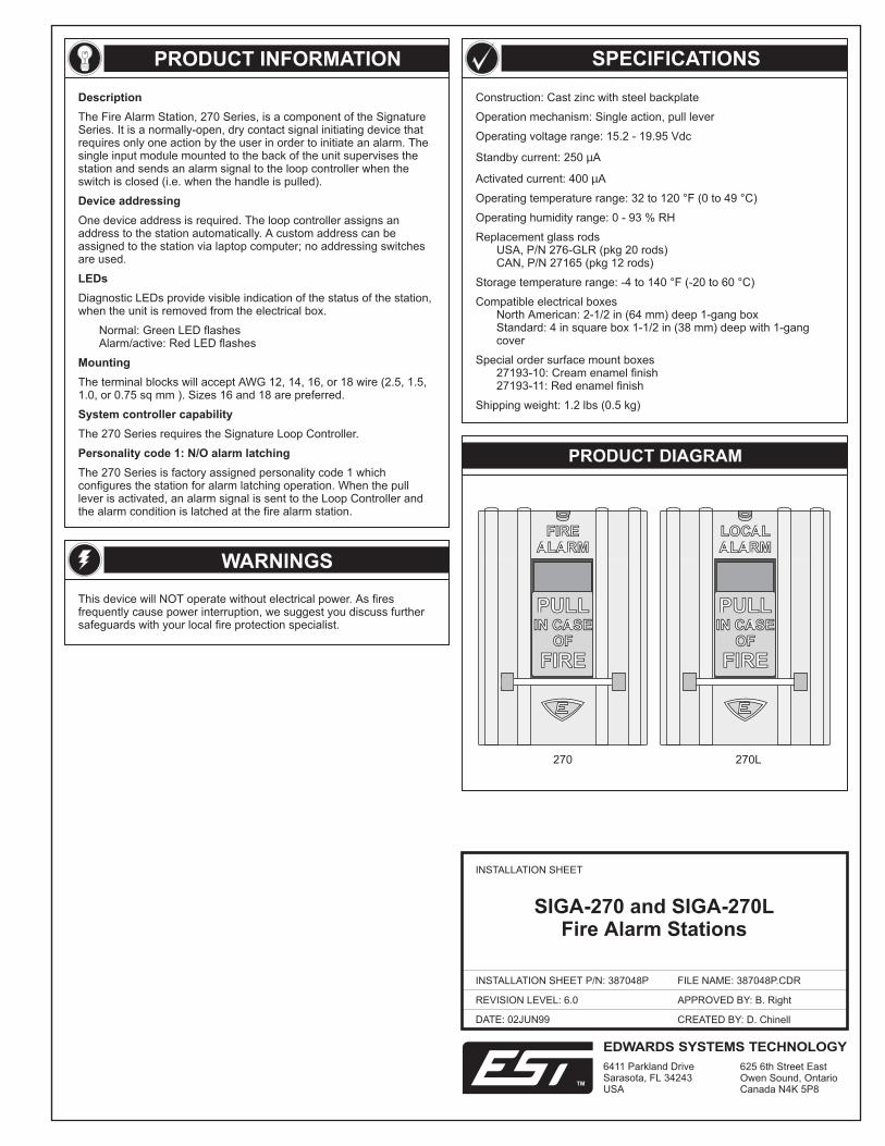
Construction: Cast zinc with steel backplate
Operation mechanism: Single action, pull lever
Operating voltage range: 15.2 - 19.95 Vdc
Standby current: 250 A
Activated current: 400 A
Operating temperature range: 32 to 120 °F (0 to 49 °C)
Operating humidity range: 0 - 93 % RH
Replacement glass rodsUSA, P/N 276-GLR (pkg 20 rods)CAN, P/N 27165 (pkg 12 rods)
Storage temperature range: -4 to 140 °F (-20 to 60 °C)
Compatible electrical boxesNorth American: 2-1/2 in (64 mm) deep 1-gang boxStandard: 4 in square box 1-1/2 in (38 mm) deep with 1-gangcover
Special order surface mount boxes27193-10: Cream enamel finish27193-11: Red enamel finish
Shipping weight: 1.2 lbs (0.5 kg)
µ
µ
PRODUCT INFORMATION
WARNINGS
This device will NOT operate without electrical power. As firesfrequently cause power interruption, we suggest you discuss furthersafeguards with your local fire protection specialist.
SPECIFICATIONS
PRODUCT DIAGRAM
DATE: 02JUN99
INSTALLATION SHEET
INSTALLATION SHEET P/N: 387048P
REVISION LEVEL: 6.0
FILE NAME: 387048P.CDR
CREATED BY: D. Chinell
APPROVED BY: B. Right
Description
Device addressing
LEDs
Mounting
System controller capability
Personality code 1: N/O alarm latching
The Fire Alarm Station, 270 Series, is a component of the SignatureSeries. It is a normally-open, dry contact signal initiating device thatrequires only one action by the user in order to initiate an alarm. Thesingle input module mounted to the back of the unit supervises thestation and sends an alarm signal to the loop controller when theswitch is closed (i.e. when the handle is pulled).
One device address is required. The loop controller assigns anaddress to the station automatically. A custom address can beassigned to the station via laptop computer; no addressing switchesare used.
Diagnostic LEDs provide visible indication of the status of the station,when the unit is removed from the electrical box.
Normal: Green LED flashesAlarm/active: Red LED flashes
The terminal blocks will accept AWG 12, 14, 16, or 18 wire (2.5, 1.5,1.0, or 0.75 sq mm ). Sizes 16 and 18 are preferred.
The 270 Series requires the Signature Loop Controller.
The 270 Series is factory assigned personality code 1 whichconfigures the station for alarm latching operation. When the pulllever is activated, an alarm signal is sent to the Loop Controller andthe alarm condition is latched at the fire alarm station.
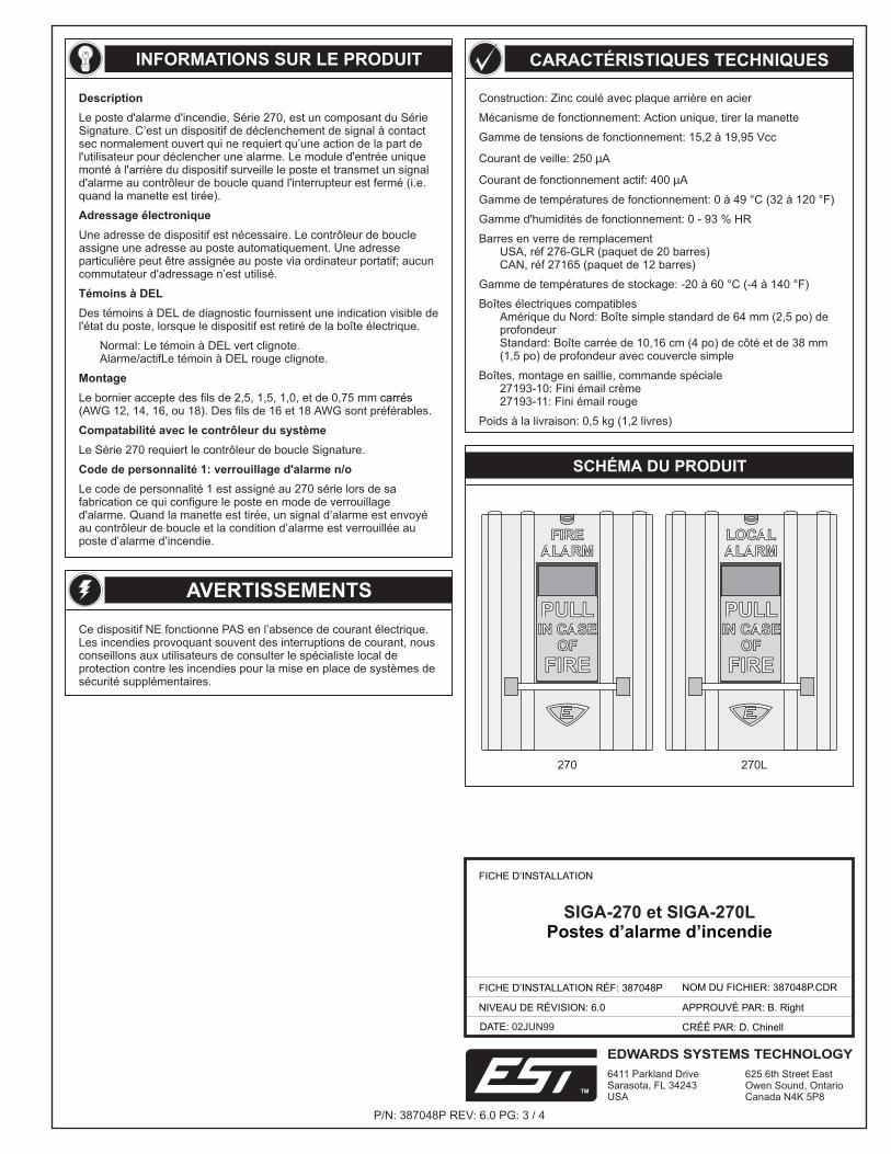
SIGA-270 and SIGA-270LFire Alarm Stations
FIREALARM
FIREALARM
PULL
FIRE
IN CASEOF
PULL
FIRE
IN CASEOF
LOCALALARMLOCALALARM
PULL
FIRE
IN CASEOF
PULL
FIRE
IN CASEOF
270 270L
EDWARDS SYSTEMS TECHNOLOGY
6411 Parkland DriveSarasota, FL 34243USA
625 6th Street EastOwen Sound, OntarioCanada N4K 5P8
TM
4 3 2 1
TB1
P/N: 387048P REV: 6.0 PG: 2 / 4
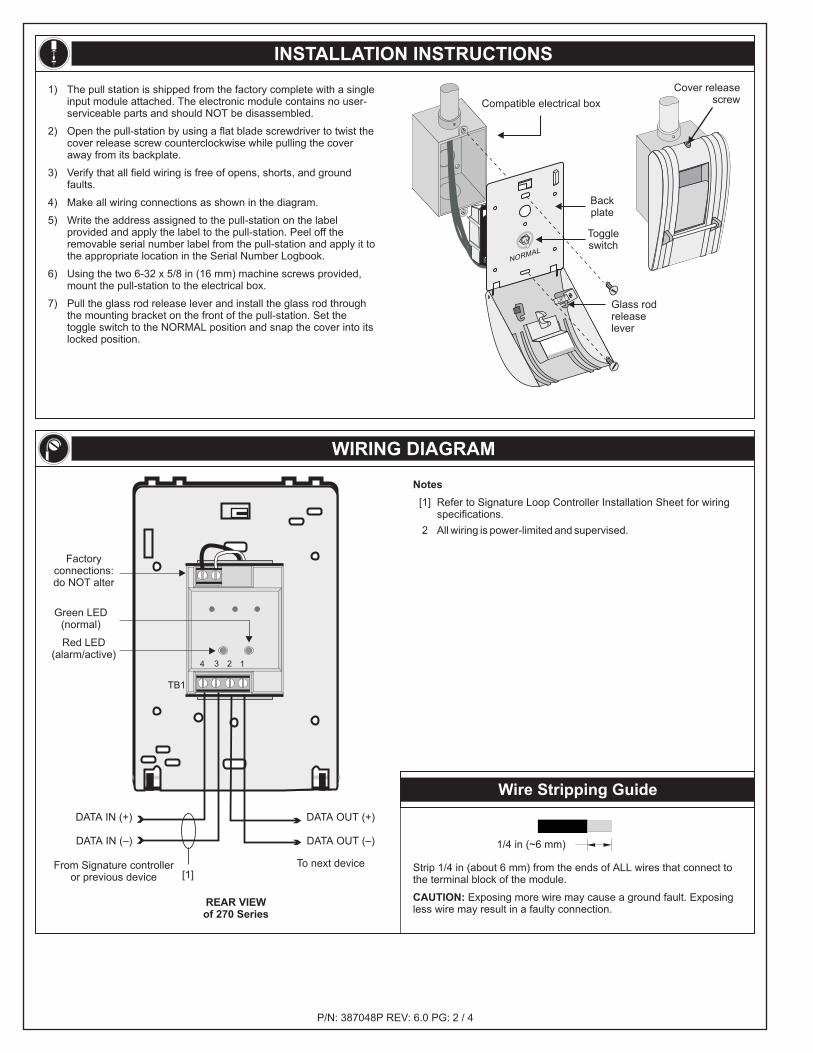
INSTALLATION INSTRUCTIONS
WIRING DIAGRAM
Notes
[1] Refer to Signature Loop Controller Installation Sheet for wiringspecifications.
2 All wiring is power-limited and supervised.
REAR VIEWof 270 Series
Factoryconnections:do NOT alter
To next deviceFrom Signature controlleror previous device
Green LED(normal)
Red LED(alarm/active)
DATA OUT (+)
DATA OUT (–)
DATA IN (+)
DATA IN (–)
Wire Stripping Guide
Strip 1/4 in (about 6 mm) from the ends of ALL wires that connect tothe terminal block of the module.
Exposing more wire may cause a ground fault. Exposingless wire may result in a faulty connection.CAUTION:
1/4 in (~6 mm)
1) The pull station is shipped from the factory complete with a singleinput module attached. The electronic module contains no user-serviceable parts and should NOT be disassembled.
2) Open the pull-station by using a flat blade screwdriver to twist thecover release screw counterclockwise while pulling the coveraway from its backplate.
3) Verify that all field wiring is free of opens, shorts, and groundfaults.
4) Make all wiring connections as shown in the diagram.
5) Write the address assigned to the pull-station on the labelprovided and apply the label to the pull-station. Peel off theremovable serial number label from the pull-station and apply it tothe appropriate location in the Serial Number Logbook.
6) Using the two 6-32 x 5/8 in (16 mm) machine screws provided,mount the pull-station to the electrical box.
7) Pull the glass rod release lever and install the glass rod throughthe mounting bracket on the front of the pull-station. Set thetoggle switch to the NORMAL position and snap the cover into itslocked position.
Compatible electrical box
LIFT
NORMAL
Toggleswitch
Backplate
Glass rodreleaselever
Cover releasescrew
[1]
INFORMATIONS SUR LE PRODUIT
AVERTISSEMENTS
Ce dispositif NE fonctionne PAS en l’absence de courant électrique.Les incendies provoquant souvent des interruptions de courant, nousconseillons aux utilisateurs de consulter le spécialiste local deprotection contre les incendies pour la mise en place de systèmes desécurité supplémentaires.
CARACTÉRISTIQUES TECHNIQUES
SCHÉMA DU PRODUIT
FICHE D’INSTALLATION
FICHE D’INSTALLATION RÉF: 387048P
NIVEAU DE RÉVISION: 6.0
NOM DU FICHIER: 387048P.CDR
APPROUVÉ PAR: B. Right
DATE: 02JUN99 CRÉÉ PAR: D. Chinell
Construction: Zinc coulé avec plaque arrière en acier
Mécanisme de fonctionnement: Action unique, tirer la manette
Gamme de tensions de fonctionnement: 15,2 à 19,95 Vcc
Courant de veille: 250 A
Courant de fonctionnement actif: 400 A
Gamme de températures de fonctionnement: 0 à 49 °C (32 à 120 °F)
Gamme d'humidités de fonctionnement: 0 - 93 % HR
Barres en verre de remplacementUSA, réf 276-GLR (paquet de 20 barres)CAN, réf 27165 (paquet de 12 barres)
Gamme de températures de stockage: -20 à 60 °C (-4 à 140 °F)
Boîtes électriques compatiblesAmérique du Nord: Boîte simple standard de 64 mm (2,5 po) deprofondeurStandard: Boîte carrée de 10,16 cm (4 po) de côté et de 38 mm(1,5 po) de profondeur avec couvercle simple
Boîtes, montage en saillie, commande spéciale27193-10: Fini émail crème27193-11: Fini émail rouge
Poids à la livraison: 0,5 kg (1,2 livres)
µ
µ
Description
Adressage électronique
Témoins à DEL
Montage
Compatabilité avec le contrôleur du système
Code de personnalité 1: verrouillage d'alarme n/o
Le poste d'alarme d'incendie, Série 270, est un composant du SérieSignature. C’est un dispositif de déclenchement de signal à contactsec normalement ouvert qui ne requiert qu’une action de la part del'utilisateur pour déclencher une alarme. Le module d'entrée uniquemonté à l'arrière du dispositif surveille le poste et transmet un signald'alarme au contrôleur de boucle quand l'interrupteur est fermé (i.e.quand la manette est tirée).
Une adresse de dispositif est nécessaire. Le contrôleur de boucleassigne une adresse au poste automatiquement. Une adresseparticulière peut être assignée au poste via ordinateur portatif; aucuncommutateur d'adressage n’est utilisé.
Des témoins à DEL de diagnostic fournissent une indication visible del'état du poste, lorsque le dispositif est retiré de la boîte électrique.
Normal: Le témoin à DEL vert clignote.Alarme/actifLe témoin à DEL rouge clignote.
Le Série 270 requiert le contrôleur de boucle Signature.
Le code de personnalité 1 est assigné au 270 série lors de safabrication ce qui configure le poste en mode de verrouillaged'alarme. Quand la manette est tirée, un signal d’alarme est envoyéau contrôleur de boucle et la condition d’alarme est verrouillée auposte d’alarme d’incendie.
Le bornier accepte des fils de 2,5, 1,5, 1,0, et de 0,75 mm(AWG 12, 14, 16, ou 18). Des fils de 16 et 18 AWG sont préférables.
carrés
FIREALARM
FIREALARM
PULL
FIRE
IN CASEOF
PULL
FIRE
IN CASEOF
LOCALALARMLOCALALARM
PULL
FIRE
IN CASEOF
PULL
FIRE
IN CASEOF
270 270L
SIGA-270 et SIGA-270LPostes d’alarme d’incendie
EDWARDS SYSTEMS TECHNOLOGY
6411 Parkland DriveSarasota, FL 34243USA
625 6th Street EastOwen Sound, OntarioCanada N4K 5P8
TM
P/N: 387048P REV: 6.0 PG: 3 / 4
4 3 2 1
TB1
SCHÉMAS DE CÂBLAGE
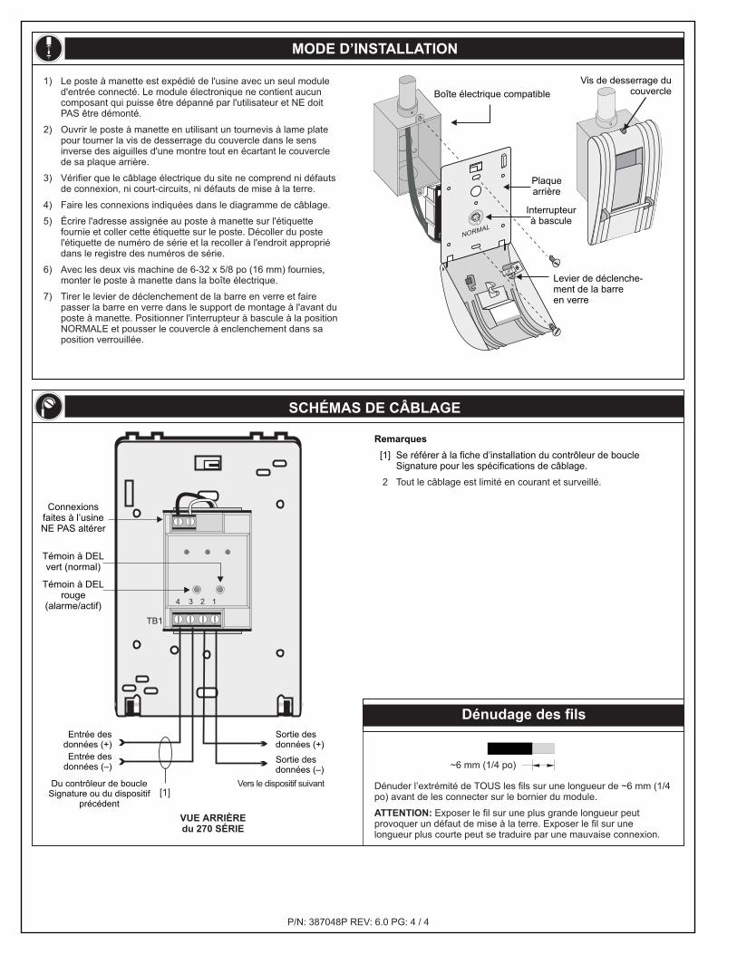
Remarques
[1] Se référer à la fiche d’installation du contrôleur de boucleSignature pour les spécifications de câblage.
2 Tout le câblage est limité en courant et surveillé.
Dénuder l’extrémité de TOUS les fils sur une longueur de ~6 mm (1/4po) avant de les connecter sur le bornier du module.
Exposer le fil sur une plus grande longueur peutprovoquer un défaut de mise à la terre. Exposer le fil sur unelongueur plus courte peut se traduire par une mauvaise connexion.
ATTENTION:
~6 mm 1/4 po( )
P/N: 387048P REV: 6.0 PG: 4 / 4
MODE D’INSTALLATION
Sortie desdonnées (+)
Sortie desdonnées (–)
Témoin à DELrouge
(alarme/actif)
Connexionsfaites à l’usineNE PAS altérer
Témoin à DELvert (normal)
Vers le dispositif suivant
Dénudage des fils
VUE ARRIÈREdu 270 SÉRIE
Du contrôleur de boucleSignature ou du dispositif
précédent
Entrée desdonnées (+)Entrée des
données (–)
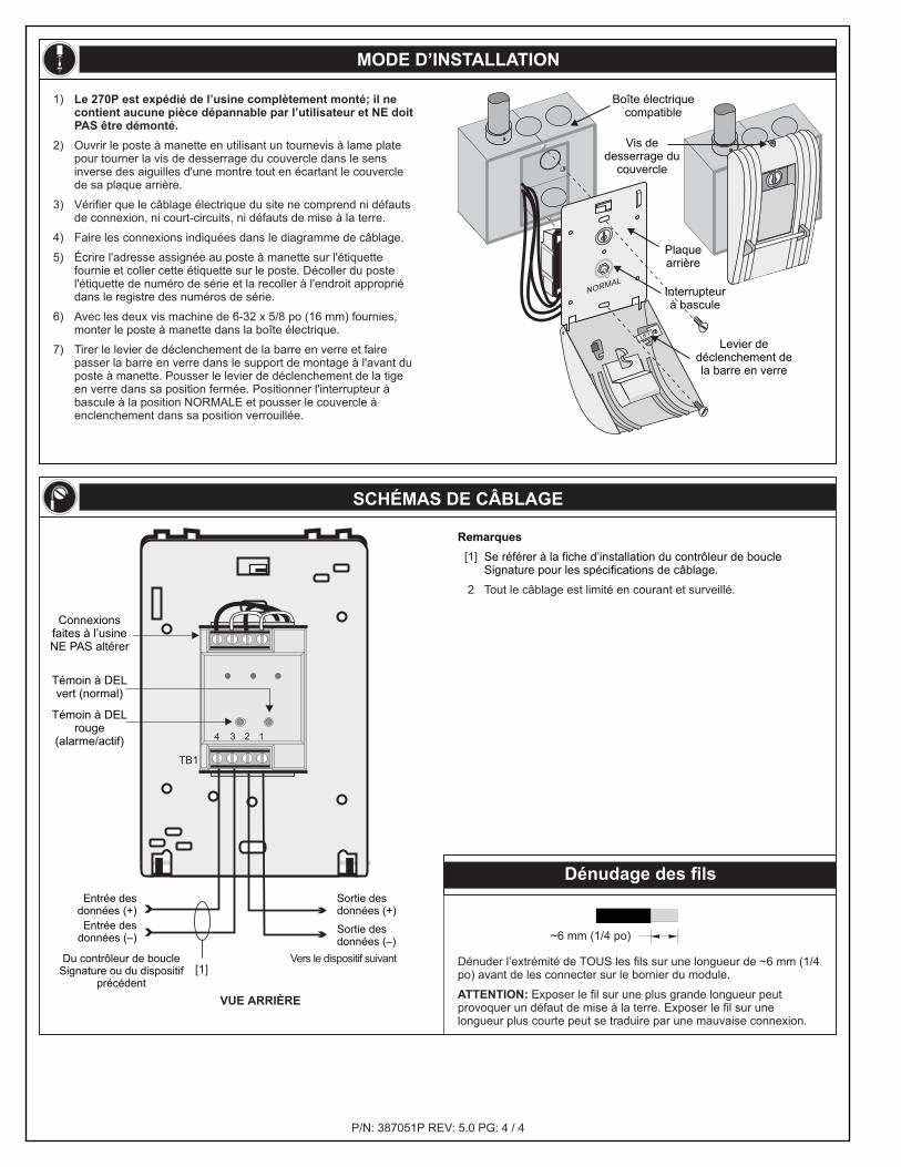
1) Le poste à manette est expédié de l'usine avec un seul moduled'entrée connecté. Le module électronique ne contient aucuncomposant qui puisse être dépanné par l'utilisateur et NE doitPAS être démonté.
2) Ouvrir le poste à manette en utilisant un tournevis à lame platepour tourner la vis de desserrage du couvercle dans le sensinverse des aiguilles d'une montre tout en écartant le couverclede sa plaque arrière.
3) Vérifier que le câblage électrique du site ne comprend ni défautsde connexion, ni court-circuits, ni défauts de mise à la terre.
4) Faire les connexions indiquées dans le diagramme de câblage.
5) Écrire l'adresse assignée au poste à manette sur l'étiquettefournie et coller cette étiquette sur le poste. Décoller du postel'étiquette de numéro de série et la recoller à l'endroit appropriédans le registre des numéros de série.
6) Avec les deux vis machine de 6-32 x 5/8 po (16 mm) fournies,monter le poste à manette dans la boîte électrique.
7) Tirer le levier de déclenchement de la barre en verre et fairepasser la barre en verre dans le support de montage à l'avant duposte à manette. Positionner l'interrupteur à bascule à la positionNORMALE et pousser le couvercle à enclenchement dans saposition verrouillée.
LIFT
NORMAL
Interrupteurà bascule
Plaquearrière
Boîte électrique compatible
Vis de desserrage ducouvercle
Levier de déclenche-ment de la barreen verre
[1]
PRODUCT INFORMATION
WARNINGS
This device will NOT operate without electrical power. As firesfrequently cause power interruption, we suggest you discuss furthersafeguards with your local fire protection specialist.
SPECIFICATIONS
DATE: 02JUN99
INSTALLATION SHEET
INSTALLATION SHEET P/N: 387051P
REVISION LEVEL: 5.0
FILE NAME: 387051P.CDR
CREATED BY: D. Chinell
APPROVED BY: B. Right
Description
Device addressing
LEDs
Mounting
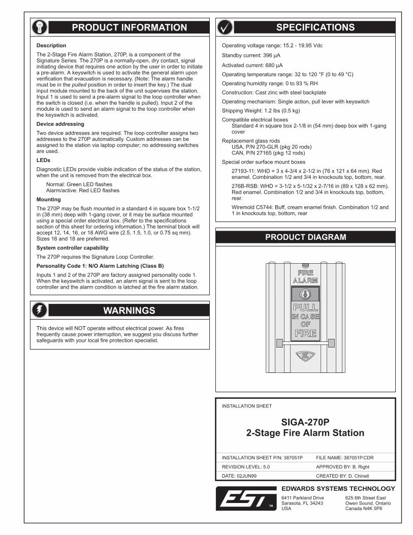
The 2-Stage Fire Alarm Station, 270P, is a component of theSignature Series. The 270P is a normally-open, dry contact, signalinitiating device that requires one action by the user in order to initiatea pre-alarm. A keyswitch is used to activate the general alarm uponverification that evacuation is necessary. (Note: The alarm handlemust be in the position in order to insert the key.) The dualinput module mounted to the back of the unit supervises the station.Input 1 is used to send a pre-alarm signal to the loop controller whenthe switch is closed (i.e. when the handle is pulled). Input 2 of themodule is used to send an alarm signal to the loop controller whenthe keyswitch is activated.
Two device addresses are required. The loop controller assigns twoaddresses to the 270P automatically. Custom addresses can beassigned to the station via laptop computer; no addressing switchesare used.
The 270P may be flush mounted in a standard 4 in square box 1-1/2in (38 mm) deep with 1-gang cover, or it may be surface mountedusing a special order electrical box. (Refer to the specificationssection of this sheet for ordering information.) The terminal block willaccept 12, 14, 16, or 18 AWG wire (2.5, 1.5, 1.0, or 0.75 sq mm).Sizes 16 and 18 are preferred.
Inputs 1 and 2 of the 270P are factory assigned personality code 1.When the keyswitch is activated, an alarm signal is sent to the loopcontroller and the alarm condition is latched at the fire alarm station.
pulled
Diagnostic LEDs provide visible indication of the status of the station,when the unit is removed from the electrical box.
Normal: Green LED flashesAlarm/active: Red LED flashes
The 270P requires the Signature Loop Controller.
System controller capability
Personality Code 1: N/O Alarm Latching (Class B)
Operating voltage range: 15.2 - 19.95 Vdc
Standby current: 396 A
Activated current: 680 A
Operating temperature range: 32 to 120 °F (0 to 49 °C)
Operating humidity range: 0 to 93 % RH
Construction: Cast zinc with steel backplate
Operating mechanism: Single action, pull lever with keyswitch
Shipping Weight: 1.2 lbs (0.5 kg)
Compatible electrical boxesStandard 4 in square box 2-1/8 in (54 mm) deep box with 1-gangcover
Replacement glass rodsUSA, P/N 270-GLR (pkg 20 rods)CAN, P/N 27165 (pkg 12 rods)
Special order surface mount boxes
27193-11: WHD = 3 x 4-3/4 x 2-1/2 in (76 x 121 x 64 mm). Redenamel. Combination 1/2 and 3/4 in knockouts top, bottom, rear.
276B-RSB: WHD = 3-1/2 x 5-1/32 x 2-7/16 in (89 x 128 x 62 mm).Red enamel. Combination 1/2 and 3/4 in knockouts top, bottom,rear.
Wiremold C5744: Buff, cream enamel finish. Combination 1/2 and1 in knockouts top, bottom, rear
µ
µ
PRODUCT DIAGRAM
FIREALARM
FIREALARM
PULL
FIRE
IN CASEOF
PULL
FIRE
IN CASEOF
SIGA-270P2-Stage Fire Alarm Station
EDWARDS SYSTEMS TECHNOLOGY
6411 Parkland DriveSarasota, FL 34243USA
625 6th Street EastOwen Sound, OntarioCanada N4K 5P8
TM
4 3 2 1
TB1
P/N: 387051P REV: 5.0 PG: 2 / 4
INSTALLATION INSTRUCTIONS
WIRING DIAGRAM
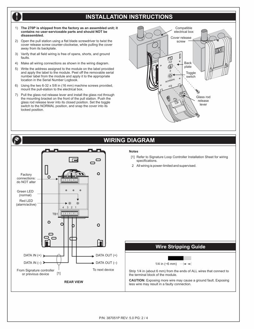
Notes
[1] Refer to Signature Loop Controller Installation Sheet for wiringspecifications.
2 All wiring is power-limited and supervised.
REAR VIEW
Factoryconnections:do NOT alter
To next deviceFrom Signature controlleror previous device
Green LED(normal)
Red LED(alarm/active)
DATA OUT (+)
DATA OUT (–)
DATA IN (+)
DATA IN (–)
Wire Stripping Guide
Strip 1/4 in (about 6 mm) from the ends of ALL wires that connect tothe terminal block of the module.
Exposing more wire may cause a ground fault. Exposingless wire may result in a faulty connection.CAUTION:
1/4 in (~6 mm)
1)
2) Open the pull station using a flat blade screwdriver to twist thecover release screw counter-clockwise, while pulling the coveraway from its backplate.
3) Verify that all field wiring is free of opens, shorts, and groundfaults.
4) Make all wiring connections as shown in the wiring diagram.
5) Write the address assigned to the module on the label providedand apply the label to the module. Peel off the removable serialnumber label from the module and apply it to the appropriatelocation in the Serial Number Logbook.
6)
7) Pull the glass rod release lever and install the glass rod throughthe mounting bracket on the front of the pull station. Push theglass rod release lever into its closed position. Set the toggleswitch to the NORMAL position, and snap the cover into itslocked position.
The 270P is shipped from the factory as an assembled unit; itcontains no user-serviceable parts and should NOT bedisassembled.
Using the two 6-32 x 5/8 in (16 mm) machine screws provided,mount the pull-station to the electrical box.
Compatibleelectrical box
Cover releasescrew
LIFT
NORMAL
Toggleswitch
Backplate
Glass rodreleaselever
[1]
INFORMATIONS SUR LE PRODUIT
AVERTISSEMENTS
Ce dispositif NE fonctionne PAS en l’absence de courant électrique.Les incendies provoquant souvent des interruptions de courant, nousconseillons aux utilisateurs de consulter le spécialiste local deprotection contre les incendies pour la mise en place de systèmes desécurité supplémentaires.
P/N: 387051P REV: 5.0 PG: 3 / 4
CARACTÉRISTIQUES TECHNIQUES
SCHÉMA DU PRODUIT
FICHE D’INSTALLATION
FICHE D’INSTALLATION RÉF: 387051P
NIVEAU DE RÉVISION: 5.0
NOM DU FICHIER: 387051P.CDR
APPROUVÉ PAR: B. Right
DATE: 02JUN99 CRÉÉ PAR: D. Chinell
Gamme de tensions de fonctionnement: 15,2 à 19,95 Vcc
Courant de veille: 396 A
Courant de fonctionnement actif: 680 A
Gamme de températures de fonctionnement: 0 à 49 °C (32 à 120 °F)
Gamme d'humidités de fonctionnement: 0 - 93 % HR
Construction: Zinc coulé avec plaque arrière en acier
Mécanisme de fonctionnement: Action unique, levier à tirer avecnterrupteur à touche
Poids à la livraison: 0,5 kg (1,2 livres)
Boîtes électriques compatiblesBoîte carrée standard de 10,16 cm (4 po) de côté et de 54 mm(2-1/8 po) de profondeur avec couvercle simple standard
Barres en verre de remplacement:USA, réf 270-GLR (paquet de 20 barres)CAN, réf 27165 (paquet de 12 barres)
Boîtes montées en saillie, commandées spécialement
27193-11: Finiémail rouge. Combinaison 1,27 cm (1/2 po) et 1,905 cm (3/4 po)débouchures en haut, en bas et à l'arrière.
276B-RSB:Fini émail rouge. Combinaison 1,27 cm (1/2 po) et 1,91 cm (3/4po) débouchures en haut, en bas et à l'arrière.
Wiremold C5744: Poli, fini émail crème. Combinaison 1,27 cm(1/2 po) et 2,54 cm (1 po) débouchures en haut, en bas et àl'arrière.
µ
µ
WHD = 76 x 121 x 64 mm (3 x 4-3/4 x 2-1/2 in).
WHD = 89 x 128 x 62 mm (3-1/2 x 5-1/32 x 2-7/16 in).
Description
Adressage électronique
Témoins à DEL
Montage
Compatabilité avec le contrôleur du système
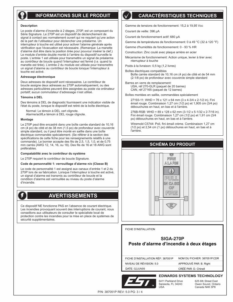
Le poste d’alarme d’incendie à 2 étages, 270P, est un composant duSérie Signature. Le 270P est un dispositif de déclenchement designal à contact sec normalement ouvert qui ne requiert qu’une actionde la part de l’utilisateur pour déclencher une préalarme. Uninterrupteur à touche est utilisé pour activer l’alarme générale aprèsvérification que l’évacuation est nécessaire. (Remarque: La manetted’alarme doit être dans la position pour pouvour insérer la clef.)Le module d’entrée double monté à l’arrière du dispositif surveille leposte. L’entrée 1 est utilisée pour transmettre un signal de préalarmeau contrôleur de boucle quand l’interrupteur est fermé (i.e. quand lamanette est tirée). L’entrée 2 du module est utilisée pour transmettreun signal d’alarme au contrôleur de boucle lorsque l’interrupteur àtouche est activé.
Deux adresses de dispositif sont nécessaires. Le contrôleur deboucle assigne deux adresses au 270P automatiquement, ou desadresses particulières peuvent être assignées au poste via ordinateurportatif; aucun commutateur d’adressage n’est utilisé.
Le 270P peut être encastré dans une boîte carrée standard de 10,16cm (4 po) de côté et de 38 mm (1,5 po) de profondeur avec couverclesimple standard, ou il peut être monté en saillie dans une boîteélectrique commandée spécialement. (Se référer à la section desspécifications de cette fiche pour les renseignements relatifs à unecommande). Le bornier accepte des fils de 2,5, 1,5, 1,0, et de 0,75mm carrés (AWG 12, 14, 16, ou 18). Des fils de 16 et 18 AWG sontpréférables.
Le code de personnalité 1 est assigné aux canaux d’entrée 1 et 2 du270P lors de sa fabrication. Lorsque l’interrupteur à touche est activé,un signal d’alarme est transmis au contrôleur de boucle et lacondition d’alarme est verrouillée au niveau du poste d’alarmed’incendie.
tirée
Des témoins à DEL de diagnostic fournissent une indication visible del'état du poste, lorsque le dispositif est retiré de la boîte électrique.
Normal: Le témoin à DEL vert clignote.Alarme/actifLe témoin à DEL rouge clignote.
Le 270P requiert le contrôleur de boucle Signature.
Code de personnalité 1: verrouillage d’alarme n/o (Classe B)
SIGA-270PPoste d’alarme d’incendie à deux étages
FIREALARM
FIREALARM
PULL
FIRE
IN CASEOF
PULL
FIRE
IN CASEOF
EDWARDS SYSTEMS TECHNOLOGY
6411 Parkland DriveSarasota, FL 34243USA
625 6th Street EastOwen Sound, OntarioCanada N4K 5P8
TM
4 3 2 1
TB1
SCHÉMAS DE CÂBLAGE
Remarques
Se référer à la fiche d’installation du contrôleur de boucleSignature pour les spécifications de câblage.
[1]
2 Tout le câblage est limité en courant et surveillé.
Dénuder l’extrémité de TOUS les fils sur une longueur de ~6 mm (1/4po) avant de les connecter sur le bornier du module.
Exposer le fil sur une plus grande longueur peutprovoquer un défaut de mise à la terre. Exposer le fil sur unelongueur plus courte peut se traduire par une mauvaise connexion.
ATTENTION:
~6 mm 1/4 po( )
P/N: 387051P REV: 5.0 PG: 4 / 4
MODE D’INSTALLATION
Sortie desdonnées (+)
Sortie desdonnées (–)
Témoin à DELrouge
(alarme/actif)
Connexionsfaites à l’usineNE PAS altérer
Témoin à DELvert (normal)
Vers le dispositif suivant
Dénudage des fils
VUE ARRIÈRE
Du contrôleur de boucleSignature ou du dispositif
précédent
Entrée desdonnées (+)Entrée des
données (–)
LIFT
NORMAL
Boîte électriquecompatible
Vis dedesserrage du
couvercle
Interrupteurà bascule
Plaquearrière
Levier dedéclenchement dela barre en verre
1)
2) Ouvrir le poste à manette en utilisant un tournevis à lame platepour tourner la vis de desserrage du couvercle dans le sensinverse des aiguilles d'une montre tout en écartant le couverclede sa plaque arrière.
3) Vérifier que le câblage électrique du site ne comprend ni défautsde connexion, ni court-circuits, ni défauts de mise à la terre.
4) Faire les connexions indiquées dans le diagramme de câblage.
5) Écrire l'adresse assignée au poste à manette sur l'étiquettefournie et coller cette étiquette sur le poste. Décoller du postel'étiquette de numéro de série et la recoller à l'endroit appropriédans le registre des numéros de série.
6) Avec les deux vis machine de 6-32 x 5/8 po (16 mm) fournies,monter le poste à manette dans la boîte électrique.
7) Tirer le levier de déclenchement de la barre en verre et fairepasser la barre en verre dans le support de montage à l'avant duposte à manette. Pousser le levier de déclenchement de la tigeen verre dans sa position fermée. Positionner l'interrupteur àbascule à la position NORMALE et pousser le couvercle àenclenchement dans sa position verrouillée.
Le 270P est expédié de l’usine complètement monté; il necontient aucune pièce dépannable par l’utilisateur et NE doitPAS être démonté.
[1]
Description
Device addressing
LEDs
Mounting
System controller compatibility
Personality code 1: N/O alarm latching (Class B)
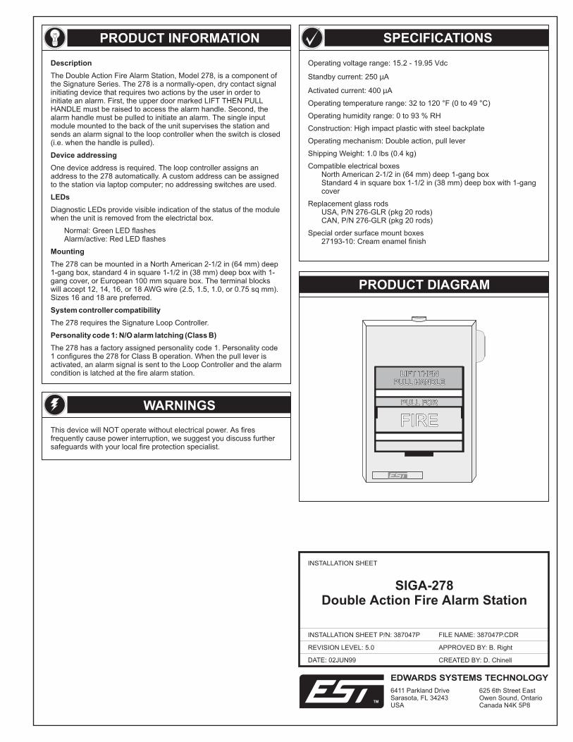
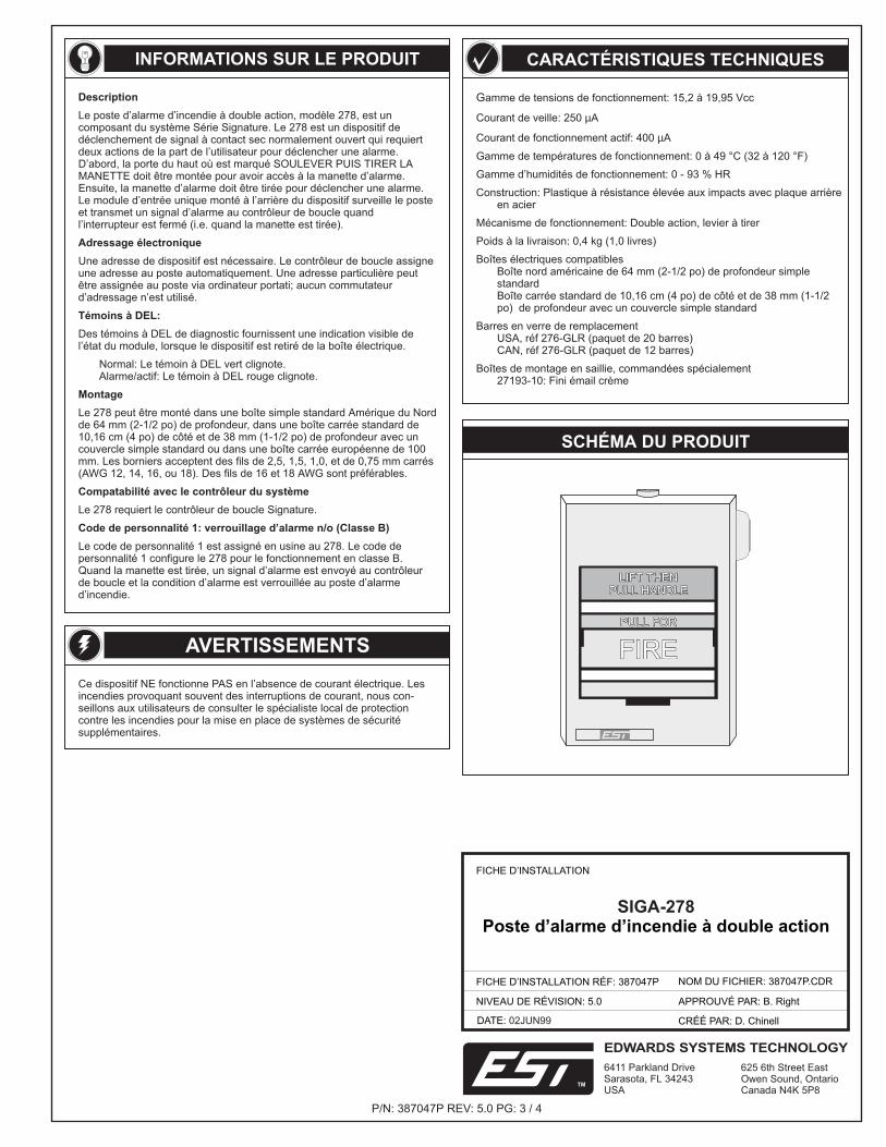
The Double Action Fire Alarm Station, Model 278, is a component ofthe Signature Series. The 278 is a normally-open, dry contact signalinitiating device that requires two actions by the user in order toinitiate an alarm. First, the upper door marked LIFT THEN PULLHANDLE must be raised to access the alarm handle. Second, thealarm handle must be pulled to initiate an alarm. The single inputmodule mounted to the back of the unit supervises the station andsends an alarm signal to the loop controller when the switch is closed(i.e. when the handle is pulled).
One device address is required. The loop controller assigns anaddress to the 278 automatically. A custom address can be assignedto the station via laptop computer; no addressing switches are used.
Diagnostic LEDs provide visible indication of the status of the modulewhen the unit is removed from the electrictal box.
Normal: Green LED flashesAlarm/active: Red LED flashes
The 278 can be mounted in a North American 2-1/2 in (64 mm) deep1-gang box, standard 4 in square 1-1/2 in (38 mm) deep box with 1-gang cover, or European 100 mm square box. The terminal blockswill accept 12, 14, 16, or 18 AWG wire (2.5, 1.5, 1.0, or 0.75 sq mm).Sizes 16 and 18 are preferred.
The 278 requires the Signature Loop Controller.
The 278 has a factory assigned personality code 1. Personality code1 configures the 278 for Class B operation. When the pull lever isactivated, an alarm signal is sent to the Loop Controller and the alarmcondition is latched at the fire alarm station.
Operating voltage range: 15.2 - 19.95 Vdc
Standby current: 250 A
Activated current: 400 A
Operating temperature range: 32 to 120 °F (0 to 49 °C)
Operating humidity range: 0 to 93 % RH
Construction: High impact plastic with steel backplate
Operating mechanism: Double action, pull lever
Shipping Weight: 1.0 lbs (0.4 kg)
Compatible electrical boxesNorth American 2-1/2 in (64 mm) deep 1-gang boxStandard 4 in square box 1-1/2 in (38 mm) deep box with 1-gangcover
Replacement glass rodsUSA, P/N 276-GLR (pkg 20 rods)CAN, P/N 276-GLR (pkg 20 rods)
Special order surface mount boxes27193-10: Cream enamel finish
µ
µ
PRODUCT DIAGRAM
PRODUCT INFORMATION
WARNINGS
This device will NOT operate without electrical power. As firesfrequently cause power interruption, we suggest you discuss furthersafeguards with your local fire protection specialist.
SPECIFICATIONS
LIFT THENPULL HANDLE
LIFT THENPULL HANDLE
PULL FORPULL FOR
FIREFIRE
DATE: 02JUN99
INSTALLATION SHEET
INSTALLATION SHEET P/N: 387047P
REVISION LEVEL: 5.0
FILE NAME: 387047P.CDR
CREATED BY: D. Chinell
APPROVED BY: B. Right
SIGA-278Double Action Fire Alarm Station
EDWARDS SYSTEMS TECHNOLOGY
6411 Parkland DriveSarasota, FL 34243USA
625 6th Street EastOwen Sound, OntarioCanada N4K 5P8
TM
P/N: 387047P REV: 5.0 PG: 2 / 4
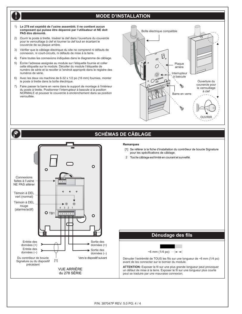
INSTALLATION INSTRUCTIONS
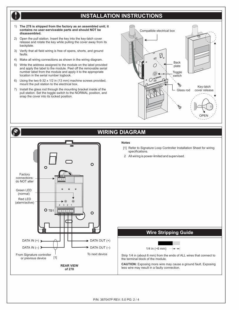
1)
2) Open the pull station. Insert the key into the key-latch coverrelease and rotate the key while pulling the cover away from itsbackplate.
3) Verify that all field wiring is free of opens, shorts, and groundfaults.
4) Make all wiring connections as shown in the wiring diagram.
5) Write the address assigned to the module on the label providedand apply the label to the module. Peel off the removable serialnumber label from the module and apply it to the appropriatelocation in the serial number logbook.
6) Using the two 6-32 x 1/2 in (13 mm) machine screws provided,mount the pull station to the electrical box.
7) Install the glass rod through the mounting bracket inside of thepull station. Set the toggle switch to the NORMAL position, andsnap the cover into its locked position.
The 278 is shipped from the factory as an assembled unit; itcontains no user-serviceable parts and should NOT bedisassembled.
Key-latchcover releaseGlass rod
Toggleswitch
Compatible electrical box
Backplate
OPEN
WIRING DIAGRAM
Notes
[1] Refer to Signature Loop Controller Installation Sheet for wiringspecifications.
2 All wiring is power-limited and supervised.
REAR VIEWof 278
Factoryconnections:do NOT alter
To next deviceFrom Signature controlleror previous device
Green LED(normal)
Red LED(alarm/active)
DATA OUT (+)
DATA OUT (–)
DATA IN (+)
DATA IN (–)
4 3 2 1
TB1
Wire Stripping Guide
Strip 1/4 in (about 6 mm) from the ends of ALL wires that connect tothe terminal block of the module.
Exposing more wire may cause a ground fault. Exposingless wire may result in a faulty connection.CAUTION:
1/4 in (~6 mm)
[1]
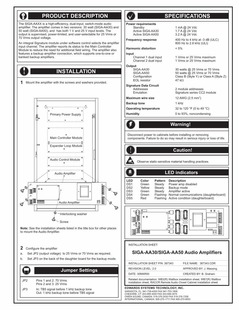
Description
Montage
Compatabilité avec le contrôleur du système
Code de personnalité 1: verrouillage d’alarme n/o (Classe B)
Le poste d’alarme d’incendie à double action, modèle 278, est uncomposant du système Série Signature. Le 278 est un dispositif dedéclenchement de signal à contact sec normalement ouvert qui requiertdeux actions de la part de l’utilisateur pour déclencher une alarme.D’abord, la porte du haut où est marqué SOULEVER PUIS TIRER LAMANETTE doit être montée pour avoir accès à la manette d’alarme.Ensuite, la manette d’alarme doit être tirée pour déclencher une alarme.Le module d’entrée unique monté à l’arrière du dispositif surveille le posteet transmet un signal d’alarme au contrôleur de boucle quandl’interrupteur est fermé (i.e. quand la manette est tirée).
Des témoins à DEL de diagnostic fournissent une indication visible del’état du module, lorsque le dispositif est retiré de la boîte électrique.
Normal: Le témoin à DEL vert clignote.Alarme/actif: Le témoin à DEL rouge clignote.
Le 278 peut être monté dans une boîte simple standard Amérique du Nordde 64 mm (2-1/2 po) de profondeur, dans une boîte carrée standard de10,16 cm (4 po) de côté et de 38 mm (1-1/2 po) de profondeur avec uncouvercle simple standard ou dans une boîte carrée européenne de 100mm. Les borniers acceptent des fils de 2,5, 1,5, 1,0, et de 0,75 mm carrés(AWG 12, 14, 16, ou 18). Des fils de 16 et 18 AWG sont préférables.
Le 278 requiert le contrôleur de boucle Signature.
Le code de personnalité 1 est assigné en usine au 278. Le code depersonnalité 1 configure le 278 pour le fonctionnement en classe B.Quand la manette est tirée, un signal d’alarme est envoyé au contrôleurde boucle et la condition d’alarme est verrouillée au poste d’alarmed’incendie.
Adressage électronique
Témoins à DEL:
Une adresse de dispositif est nécessaire. Le contrôleur de boucle assigneune adresse au poste automatiquement. Une adresse particulière peutêtre assignée au poste via ordinateur portati; aucun commutateurd’adressage n’est utilisé.
INFORMATIONS SUR LE PRODUIT
AVERTISSEMENTS
Ce dispositif NE fonctionne PAS en l’absence de courant électrique. Lesincendies provoquant souvent des interruptions de courant, nous con-seillons aux utilisateurs de consulter le spécialiste local de protectioncontre les incendies pour la mise en place de systèmes de sécuritésupplémentaires.
Gamme de tensions de fonctionnement: 15,2 à 19,95 Vcc
Courant de veille: 250 A
Courant de fonctionnement actif: 400 A
Gamme de températures de fonctionnement: 0 à 49 °C (32 à 120 °F)
Gamme d’humidités de fonctionnement: 0 - 93 % HR
Construction: Plastique à résistance élevée aux impacts avec plaque arrièreen acier
Mécanisme de fonctionnement: Double action, levier à tirer
Poids à la livraison: 0,4 kg (1,0 livres)
Boîtes électriques compatiblesBoîte nord américaine de 64 mm (2-1/2 po) de profondeur simplestandardBoîte carrée standard de 10,16 cm (4 po) de côté et de 38 mm (1-1/2po) de profondeur avec un couvercle simple standard
Barres en verre de remplacementUSA, réf 276-GLR (paquet de 20 barres)CAN, réf 276-GLR (paquet de 12 barres)
Boîtes de montage en saillie, commandées spécialement27193-10: Fini émail crème
µ
µ
P/N: 387047P REV: 5.0 PG: 3 / 4
CARACTÉRISTIQUES TECHNIQUES
SCHÉMA DU PRODUIT
LIFT THENPULL HANDLE
LIFT THENPULL HANDLE
FIREFIREPULL FORPULL FOR
FICHE D’INSTALLATION
SIGA-278Poste d’alarme d’incendie à double action
FICHE D’INSTALLATION RÉF: 387047P
NIVEAU DE RÉVISION: 5.0
NOM DU FICHIER: 387047P.CDR
APPROUVÉ PAR: B. Right
DATE: 02JUN99 CRÉÉ PAR: D. Chinell
EDWARDS SYSTEMS TECHNOLOGY
6411 Parkland DriveSarasota, FL 34243USA
625 6th Street EastOwen Sound, OntarioCanada N4K 5P8
TM
Boîte électrique compatible
SCHÉMAS DE CÂBLAGE
Remarques
[1] Se référer à la fiche d’installation du contrôleur de boucle Signaturepour les spécifications de câblage.
Tout le câblage est limité en courant et surveillé.2
4 3 2 1
TB1
Dénuder l’extrémité de TOUS les fils sur une longueur de ~6 mm (1/4 po)avant de les connecter sur le bornier du module.
Exposer le fil sur une plus grande longueur peut provoquerun défaut de mise à la terre. Exposer le fil sur une longueur plus courtepeut se traduire par une mauvaise connexion.
ATTENTION:
~6 mm 1/4 po( )
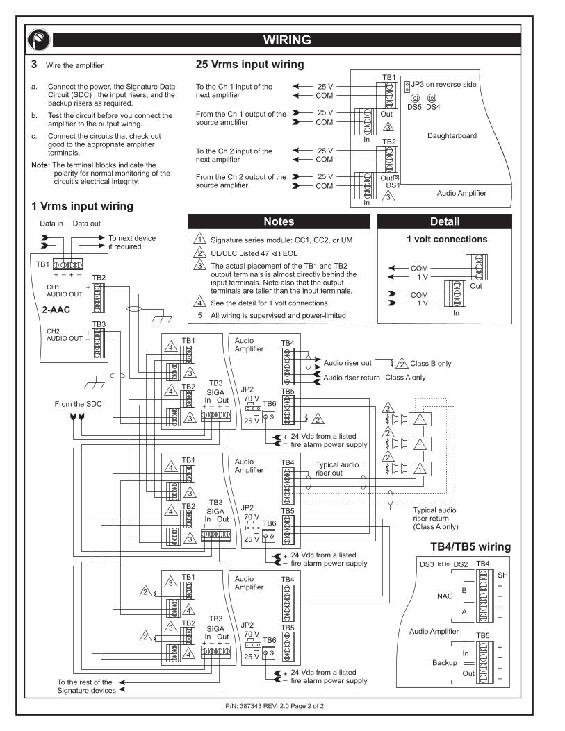
1)
2) Ouvrir le poste à tirette. Insérer la clef dans l’ouverture du couverclepour le verrouillage à clef et tourner la clef tout en écartant lecouvercle de sa plaque arrière.
3) Vérifier que le câblage électrique du site ne comprend ni défauts deconnexion, ni court-circuits, ni défauts de mise à la terre.
4) Faire toutes les connexions indiquées dans le diagramme de câblage.
5) Écrire l’adresse assignée au module sur l’étiquette fournie et collercette étiquette sur le module. Décoller du module l’étiquette denuméro de série et la recoller à l’endroit approprié dans le registre desnuméros de série.
6) Avec les deux vis machine de 6-32 x 1/2 po (16 mm) fournies, monterle poste à tirette dans la boîte électrique.
7) Faire passer la barre en verre dans le support de montage à l’intérieurdu poste à tirette. Positionner l’interrupteur à bascule à la positionNORMALE et pousser le couvercle à enclenchement dans sa positionverrouillée.
Le 278 est expédié de l’usine assemblé; il ne contient aucuncomposant qui puisse être dépanné par l’utilisateur et NE doitPAS être démonté.
P/N: 387047P REV: 5.0 PG: 4 / 4
MODE D’INSTALLATION
Ouverture ducouvercle pourle verrouillage
à clef
OUVRIR
Barre en verre
Interrupteurà bascule
Plaquearrière
VUE ARRIÈREdu 278 SÉRIE
Témoin à DELrouge
(alarme/actif)
Connexionsfaites à l’usineNE PAS altérer
Témoin à DELvert (normal)
Entrée desdonnées (+)Entrée des
données (–)
Sortie desdonnées (+)
Sortie desdonnées (–)
Du contrôleur de boucleSignature ou du dispositif
précédent
Vers le dispositif suivant
Dénudage des fils
[1]
PRODUCT DESCRIPTION SPECIFICATIONSPower requirements
Frequency response
Harmonic distortion
Input
Output
Signature Data Circuit
Maximum wire size
Backup tone
Operating temperature
Humidity
Standby 1 mA @ 24 VdcActive SIGA-AA30 1.7 A @ 24 VdcActive SIGA-AA50 3.2 A @ 24 Vdc
400 Hz to 4 kHz at -3 dB (ULC)800 Hz to 2.8 kHz (ULI)
< 5%
Channel 1 dual input 1 Vrms or 25 Vrms maximumChannel 2 dual input 1 Vrms or 25 Vrms maximum
SIGA-AA30 30 watts @ 25 Vrms or 70 VrmsSIGA-AA50 50 watts @ 25 Vrms or 70 VrmsConfiguration Class B (Style Y) or Class A (Style Z)EOL resistor 47 k
Addresses 2 module addressesEmulation Signature series CC2 module
12 AWG (2.5 mm )
1 kHz
32 to 120 F (0 to 49 C)
0 to 93%, noncondensing
2
° °
INSTALLATION
The SIGA-AAXX is a high-efficiency, dual-input, switch-mode audioamplifier. The amplifier comes in two versions: 30 watt (SIGA-AA30) and50 watt (SIGA-AA50), and has both 1 V and 25 V input levels. Theoutput is supervised, power-limited, and user-selectable for 25 Vrms or70 Vrms output voltage.
An integral Signature module under software control selects the amplifierinput channel. The amplifier reports its status to the Main ControllerModule to reduce the need for additional field wiring. The amplifier alsofeatures a backup amplifier connection, which supports one-to-one orbanked backup amplifiers.
Mount the amplifier with the screws and washers provided.
a. Set JP2 (output voltage) to 25 Vrms or 70 Vrms as required.
b. Set JP3 on the back of the daughter board for the backup mode.
DATE: 30MAR00
Related documentation: WB3(R) Wallbox installation sheet, WB7(R) Wallboxinstallation sheet, RACCR Remote Audio Closet Cabinet installation sheet
INSTALLATION SHEET:
INSTALLATION SHEET P/N: 387343
REVISION LEVEL: 2.0
FILE NAME: 387343.CDR
CREATED BY: B. Graham
APPROVED BY: J. Massing
SIGA-AA30/SIGA-AA50 Audio Amplifiers
Warning!
Jumper Settings
Disconnect power to cabinets before installing or removingcomponents. Failure to do so may result in serious injury or loss of life.
! Caution!
LED indicators
Observe static-sensitive material handling practices.
JP2 Pins 1 and 2: 70 VrmsPins 2 and 3: 25 Vrms
JP3 In: TB5 signal before 1 kHz backup toneOut: 1 kHz backup tone before TB5 signal
1
2 Configure the amplifier
Screw
Interlocking washer
Audio Amplifier
Primary Power Supply
Main Controller Module
Expander Loop Module
Audio Control Module
Audio Amplifier
LED Color Pattern DescriptionDS1 Green Steady Power amp disabledDS2 Yellow Steady Backup modeDS3 Green Steady Amplifier activeDS4 Green Flashing Normal communications (daughterboard)DS5 Red Flashing Active condition (daughterboard)
Note: See the installation sheets listed in the title box for other placesto mount the Audio Amplifier.
EDWARDS SYSTEMS TECHNOLOGY, INC.SARASOTA, FL: 941-739-4300 FAX 941-753-1806CHESHIRE, CT: 203-699-3000 FAX 203-699-3075OWEN SOUND, CANADA: 519-376-2430 FAX 519-376-7258INTERNATIONAL, CANADA: 905-270-1711 FAX 905-270-9553
P/N: 387343 REV: 2.0 Page 2 of 2
WIRING
2-AAC
TB1
TB2
TB3
TB1
TB2
TB6
TB4
TB5
TB1
TB2
TB6
TB4
TB5
TB1
TB2
24 Vdc from a listedfire alarm power supply
24 Vdc from a listedfire alarm power supply
24 Vdc from a listedfire alarm power supply
To the rest of theSignature devices
1
1
1
1
2
2
2
2
2
4
2
3
5
3
3
3
3
3
3
3
3
4
4
4
4
4
4
2
2Typical audioriser out
Typical audioriser return(Class A only)
Audio riser out
Audio riser return
From the SDC
To next deviceif required
Out
Out
Out
In
In
In
DS5
JP3 on reverse side
DS4
DS1
TB3
TB3
TB3
TB1
TB2
25 V
25 V
25 V
25 V
1 V
1 V
COM
COM
COM
COM
COM
COM
+
+
+
+
+
+
_
_
_
_
_
_
SIGA
SIGA
SIGA
In
In
In
Out
Out
Out
Notes Detail
Signature series module: CC1, CC2, or UM
UL/ULC Listed 47 k EOL
All wiring is supervised and power-limited.
The actual placement of the TB1 and TB2output terminals is almost directly behind theinput terminals. Note also that the outputterminals are taller than the input terminals.
See the detail for 1 volt connections.
Daughterboard
a. Connect the power, the Signature DataCircuit (SDC) , the input risers, and thebackup risers as required.
b. Test the circuit before you connect theamplifier to the output wiring.
c. Connect the circuits that check outgood to the appropriate amplifierterminals.
The terminal blocks indicate thepolarity for normal monitoring of thecircuit’s electrical integrity.
Note:
3 Wire the amplifier 25 Vrms input wiring
TB4/TB5 wiring
1 Vrms input wiring
To the Ch 1 input of thenext amplifier
To the Ch 2 input of thenext amplifier
From the Ch 1 output of thesource amplifier
From the Ch 2 output of thesource amplifier
+
+
+
_
_
_
TB6
JP2
JP2
JP2
TB4
TB5
25 V
25 V
25 V
70 V
70 V
70 V
Class B only
Class A only
Audio Amplifier
+
+
_
_
Out
In
+
+
_
_
A
B
SH
NAC
Backup
TB5
TB4DS3 DS2
Audio Amplifier
AudioAmplifier
AudioAmplifier
AudioAmplifier
1 volt connections
CH1AUDIO OUT
+_
+_
++ _ _
CH2AUDIO OUT
Data outData in
INSTALLATION SHEET:
DRAWING PART NO.: 270754P
REVISION LEVEL: 1.12CREATED BY: RW
FILE NAME: 270754.CDR
DATE: 08/12/97
APPROVED BY: RR
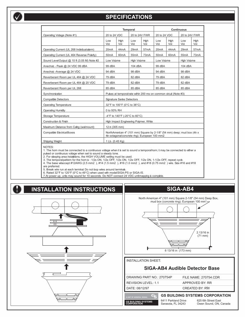
SIGA-AB4 Audible Detector Base
SPECIFICATIONS
INSTALLATION INSTRUCTIONS SIGA-AB4
6 13/16 in (173 mm)
2.13/16 in(71 mm)
North American 4" (101 mm) Square 2-1/8" (54 mm) Deep Box,2
mud box (concrete ring); European 100 mm .
GS BUILDING SYSTEMSCORPORATION
GS BUILDING SYSTEMS CORPORATION
6411 Parkland Drive 625 6th Street EastSarasota, FL 34243 Owen Sound, ON, Canada
A UNIT OF GENERAL SIGNAL
Temporal Continuous
Operating Voltage (Note #1) 20 to 24 VDC 20 to 24V FWR 20 to 24 VDC 20 to 24V FWR
LowVol.
HighVol.
LowVol.
HighVol.
LowVol.
High HighVol. Vol.
LowVol.
Operating Current (UL 268 Individual alarm) 20mA 44mA 29mA 57mA 20mA 44mA 57mA29mA
Operating Current (UL 464 Reverse Polarity) 50mA 60mA 55mA 73mA 50mA 60mA 73mA55mA
Sound Level Output @ 10 ft (3.05 M) Note #2 Low Volume High Volume Low Volume High Volume
Anechoic - Peak @ 24 VDC 99 dBA 99 dBA 104 dBA 99 dBA 104 dBA
Anechoic - Average @ 24 VDC 94 dBA 98 dBA 94 dBA 98 dBA
Reverberant Room per UL 464 @ 24 VDC 79 dBA 82 dBA 79 dBA 82 dBA
Reverberant Room per UL 464 @ 20 VDC 79 dBA 82 dBA 79 dBA 82 dBA
Reverberant Room per UL 268 85 dBA 85 dBA 85 dBA 85 dBA
Synchronization Pulses at temporal rate within 200 ms on common circuit (Note #3)
Compatible Detectors Signature Series Detectors
Operating Temperature 32°F to 100°F (0°C to 38°C)
Operating Humidity 0 to 93% RH
Storage Temperature -4°F to 140°F (-20°C to 60°C)
Construction & Finish High Impact Engineering Polymer, White
Maximum Distance from Ceiling (wall mount) 12 in (305 mm)
Compatible Electrical Boxes North American 4" (101 mm) Square by 2-1/8" (54 mm) deep; mud box (4in x4in octagonal concrete ring); European 100 mm2
Shipping Weight 1 Lb. (0.45 Kg)
NOTES:1. The horn must be connected to a continuous voltage when it is set to sound a temporal horn; it may be connected to either apulsed or continuous voltage when set to sound a steady tone.2. For sleeping area installations, the HIGH VOLUME setting must be used.3. The temporal pattern for the horn is : 1/2s ON, 1/2s OFF, 1/2s ON, 1/2s OFF, 1/2s ON, 1-1/2s OFF, repeat cycle.4. The base will accept #12 AWG (2.5 mm2 ), #14 (1.5 mm2 ), #16 (1.0 mm2 ), and #18 (0.75 mm2 ) wire. Size #16 and #18are preferred.5. Break wire run at each terminal. Do not loop wires around terminals.6. Rated 32°F to 120°F (0°C to 49°C) when used with model SIGA-PS or SIGA-IS.7. At power up, units may sound for 10 seconds. Do NOT connect 24 VDC until mapping is complete.
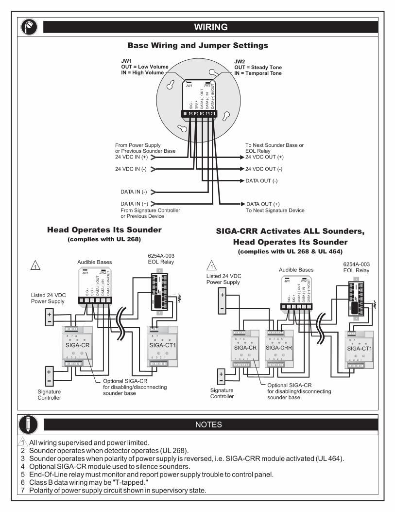
WIRING
NOTES
1 All wiring supervised and power limited.2 Sounder operates when detector operates (UL 268).3 Sounder operates when polarity of power supply is reversed, i.e. SIGA-CRR module activated (UL 464).4 Optional SIGA-CR module used to silence sounders.5 End-Of-Line relay must monitor and report power supply trouble to control panel.6 Class B data wiring may be "T-tapped."7 Polarity of power supply circuit shown in supervisory state.
Head Operates Its Sounder(complies with UL 268)
SIGA-CRR Activates ALL Sounders,
Head Operates Its Sounder(complies with UL 268 & UL 464)
DATA IN (-)
DATA OUT (-)
From Signature Controlleror Previous Device
From Power Supplyor Previous Sounder Base
To Next Sounder Base orEOL Relay
To Next Signature Device
DATA IN (+)
24 VDC IN (+) 24 VDC OUT (+)
24 VDC IN (-) 24 VDC OUT (-)
DATA OUT (+)
DA
TA
(+
) IN
/OU
T
DA
TA
(-)
IN
DA
TA
(-)
OU
T
SIG
+
JW1 JW2
SIG
-
JW2OUT = Steady ToneIN = Temporal Tone
JW1OUT = Low VolumeIN = High Volume
Base Wiring and Jumper Settings
Listed 24 VDCPower Supply
Audible Bases6254A-003EOL Relay
SignatureController
Optional SIGA-CRfor disabling/disconnectingsounder base
Listed 24 VDCPower Supply
Optional SIGA-CRfor disabling/disconnectingsounder base
Signature Controller
Audible Bases6254A-003EOL Relay
11
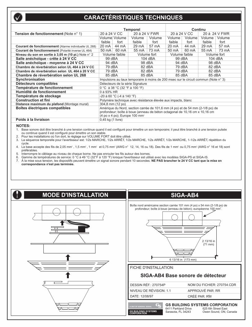
Temporel Continu20 24 V CC 20 24 V FWR 20 24 V CC 20 24 V FWRVolume Volume Volume Volume
( 50 mA 60 mA 55 mA 73 mA 50 mA 60 mA 55 mA 73 mA Volume faible ort Volume faible ort
99 104 dBA 99 dBA 104 dBA94 dBA 98 dBA 94 dBA 98 dBA79 dBA 82 dBA 79 dBA 82 dBA
UL 464 20 V CC 79 dBA 82 dBA 79 dBA 82 dBA UL 268 85 dBA 85 dBA 85 dBA 85 dBA
Tension de fonctionnement (Note n° 1) à à à à
Courant de fonctionnement Alarme individuelle UL 268)
Courant de fonctionnement Polarité inverse UL 464)
Niveau du son en sortie à 3,05 m (10 pi.) Note n° 2
Salle anéchoïque - crête à 24 V CC Salle anéchoïque - moyenne à 24 V CC Chambre de réverbération selon UL 464 à 24 V CC
Chambre de réverbération selon à
Chambre de réverbération selon Synchronisation Impulsions au taux temporaire à moins de 200 msec sur le circuit commun (Note n° 3)
Détecteurs compatibles Détecteurs de la série Signature
Température de fonctionnement 0 °C à 38 °C (32 °F à 100 °F)
Humidité de fonctionnement 0 à 93% HR
Température de stockage -20 à 60 °C (-4 à 140 °F)
Construction et fini Polymère technique avec résistance élevée aux impacts, blanc Distance maximum du plafond (Montage mural) 304,8 mm (12 po) Boîtes électriques compatibles Amérique du Nord, section carrée de 101,6 mm (4 po) et de 54 mm (2-1/8 po) de
profondeur; boîte à boue (anneau de béton octagonal de 10,16 cm x 10,16 cm 2(4 po x 4 po); Europe 100 mm
Poids à la livraison 0,45 kg (1 livre)
NOTES:1. Base sonore doit être branché à une tension continue quand il est configuré pour émettre un son temporaire; il peut être branché à une tension pulsée
ou continue quand il est configuré pour émettre un son stable.2. Pour les installations où l'on dort, le réglage sur VOLUME FORT doit être utilisé.3. La séquence temporelle pour l'avertisseur est: 1/2s MARCHE, 1/2s ARRÊT, 1/2s MARCHE, 1/2s ARRÊT, 1/2s MARCHE, 1-1/2s ARRÊT, répétition du
cycle. 2 2 2 2 2 24. La base accepte des fils de 2,05 mm , 1,5 mm , 1 mm et 0,75 mm (AWG n° 12, 14, 16 ou 18). Des fils de 1 mm ou 0,75 mm (AWG n° 16 et 18) sont
préférables.5. Interrompre le câblage au niveau de chaque borne. Ne pas enrouler les fils autour des bornes.6. Gamme de températures de service: 0 °C à 49 °C (32°F à 120 °F) lorsque l'avertisseur est utilisé avec les modèles SIGA-PS et SIGA-IS.7. À la mise sous tension, les dispositifs peuvent émettre un signal sonore pendant 10 secondes. NE PAS brancher le 24 V CC tant que la mise en
correspondance n'est pas terminée.
Volume Volume Volume Volumefaible fort faible fort faible fort faible fort
( 20 mA 44 mA 29 mA 57 mA 20 mA 44 mA 29 mA 57 mA
Volume f Volume fdBA
FICHE D'INSTALLATION:
DESSIN RÉF.: 270754P
NIVEAU DE RÉVISION: 1.12CRÉÉ PAR: RW
NOM DU FICHIER: 270754.CDR
DATE: 12/08/97
APPROUVÉ PAR: RR
SIGA-AB4 Base sonore de détecteur
CARACTÉRISTIQUES TECHNIQUES
MODE D'INSTALLATION SIGA-AB4
6 13/16 in (173 mm)
2.13/16 in(71 mm)
Boîte nord américaine section carrée 101 mm (4 po) x 54 mm (2-1/8 po) de 2
profondeur; boîte à boue (anneau de béton); européenne 100 mm .
GS BUILDING SYSTEMS CORPORATION6411 Parkland Drive 625 6th Street EastSarasota, FL 34243 Owen Sound, ON, CanadaGS BUILDING SYSTEMS
CORPORATION
A UNIT OF GENERAL SIGNAL
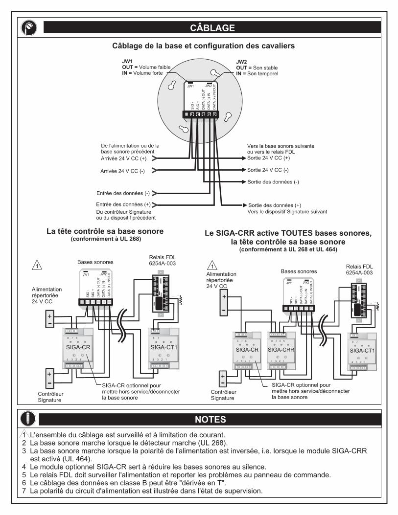
CÂBLAGE
NOTES
1 L'ensemble du câblage est surveillé et à limitation de courant.2 La base sonore marche lorsque le détecteur marche (UL 268).3 La base sonore marche lorsque la polarité de l'alimentation est inversée, i.e. lorsque le module SIGA-CRR
est activé (UL 464).4 Le module optionnel SIGA-CR sert à réduire les bases sonores au silence.5 Le relais FDL doit surveiller l'alimentation et reporter les problèmes au panneau de commande.6 Le câblage des données en classe B peut être "dérivée en T".7 La polarité du circuit d'alimentation est illustrée dans l'état de supervision.
La tête contrôle sa base sonore (conformément à UL 268)
Le SIGA-CRR active TOUTES bases sonores, la tête contrôle sa base sonore
(conformément à UL 268 et UL 464)
Entrée des données (-)
Sortie des données (-)
Du contrôleur Signature ou du dispositif précédent
De l'alimentation ou de la base sonore précédent
Vers la base sonore suivante ou vers le relais FDL
Vers le dispositif Signature suivant
Entrée des données (+)
Arrivée 24 V CC (+) Sortie 24 V CC (+)
Arrivée 24 V CC (-) Sortie 24 V CC (-)
Sortie des données (+)
DA
TA
(+
) IN
/OU
T
DA
TA
(-)
IN
DA
TA
(-)
OU
T
SIG
+
JW1 JW2
SIG
-
JW2OUT = IN =
Son stableSon temporel
JW1OUT = IN =
Volume faibleVolume forte
Câblage de la base et configuration des cavaliers
Alimentation répertoriée 24 V CC
Bases sonores
Relais FDL 6254A-003
Contrôleur Signature
Contrôleur Signature
SIGA-CR optionnel pour mettre hors service/déconnecter la base sonore
SIGA-CR optionnel pour mettre hors service/déconnecter la base sonore
11
Alimentation répertoriée 24 V CC
Bases sonoresRelais FDL 6254A-003
PRODUCT DESCRIPTION SPECIFICATIONS
DATE: 30MAR00
INSTALLATION SHEET:
INSTALLATION SHEET P/N: 387342 FILE NAME: 387342.CDR
REVISION LEVEL: 2.0
CREATED BY: B. Graham
APPROVED BY: J. Massing
SIGA-APS (-220)Auxiliary Power Supply Module
Warning!
Disconnect power to cabinets before installing or removing components. Failure to do so may result in serious injury or loss of life.
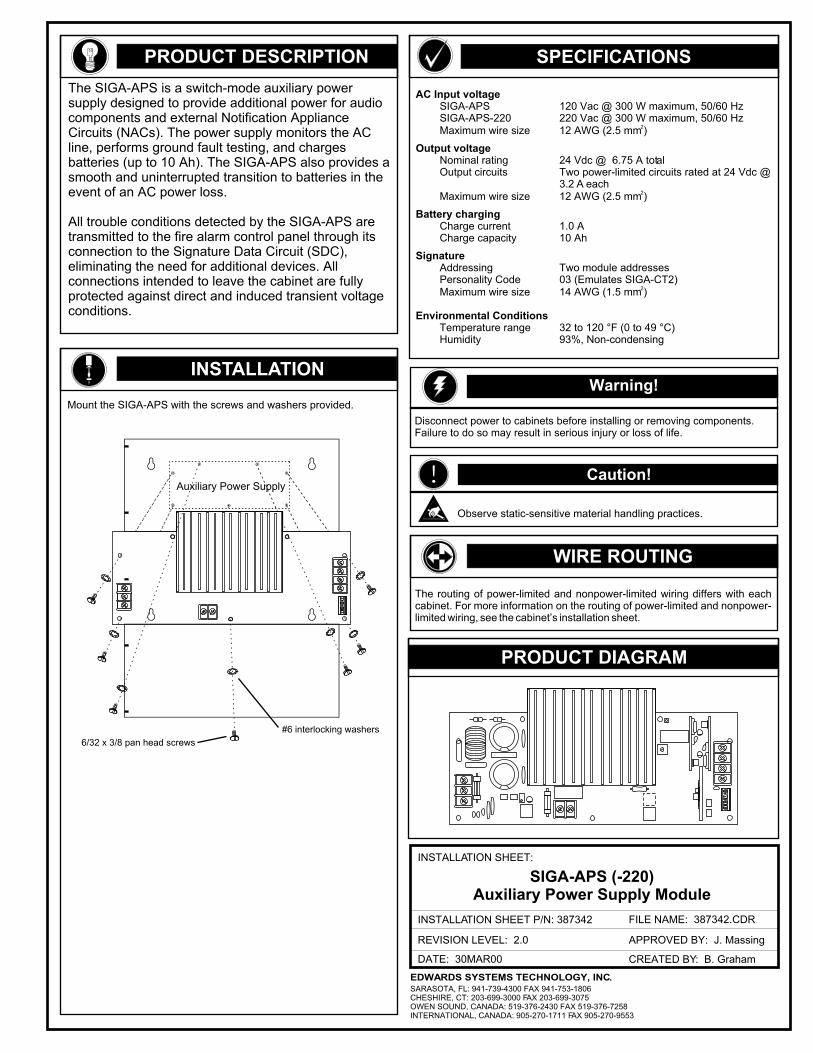
AC Input voltageSIGA-APS 120 Vac @ 300 W maximum, 50/60 HzSIGA-APS-220 220 Vac @ 300 W maximum, 50/60 Hz
2Maximum wire size 12 AWG (2.5 mm )
Output voltageNominal rating 24 Vdc @ 6.75 A totalOutput circuits Two power-limited circuits rated at 24 Vdc @
3.2 A each2Maximum wire size 12 AWG (2.5 mm )
Battery chargingCharge current 1.0 ACharge capacity 10 Ah
SignatureAddressing Two module addressesPersonality Code 03 (Emulates SIGA-CT2)
2Maximum wire size 14 AWG (1.5 mm )
Environmental ConditionsTemperature range 32 to 120 °F (0 to 49 °C)Humidity 93%, Non-condensing
INSTALLATION
Mount the SIGA-APS with the screws and washers provided.
! Caution!
Observe static-sensitive material handling practices.
The routing of power-limited and nonpower-limited wiring differs with each cabinet. For more information on the routing of power-limited and nonpower-limited wiring, see the cabinet’s installation sheet.
WIRE ROUTING
PRODUCT DIAGRAM
#6 interlocking washers
6/32 x 3/8 pan head screws
The SIGA-APS is a switch-mode auxiliary power supply designed to provide additional power for audio components and external Notification Appliance Circuits (NACs). The power supply monitors the AC line, performs ground fault testing, and charges batteries (up to 10 Ah). The SIGA-APS also provides a smooth and uninterrupted transition to batteries in the event of an AC power loss.
All trouble conditions detected by the SIGA-APS are transmitted to the fire alarm control panel through its connection to the Signature Data Circuit (SDC), eliminating the need for additional devices. All connections intended to leave the cabinet are fully protected against direct and induced transient voltage conditions.
Auxiliary Power Supply
EDWARDS SYSTEMS TECHNOLOGY, INC.SARASOTA, FL: 941-739-4300 FAX 941-753-1806CHESHIRE, CT: 203-699-3000 FAX 203-699-3075OWEN SOUND, CANADA: 519-376-2430 FAX 519-376-7258INTERNATIONAL, CANADA: 905-270-1711 FAX 905-270-9553
WIRING
387342.CDR REV 2.0 Page 2 of 2
Wire Stripping Guide
1/4 inch (6.4 mm)
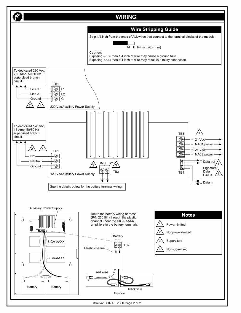
Strip 1/4 inch from the ends of ALL wires that connect to the terminal blocks of the module.
Caution:Exposing more than 1/4 inch of wire may cause a ground fault.Exposing less than 1/4 inch of wire may result in a faulty connection.
L1
L2
G
TB1
TB1
TB2
TB3
TB4
24 Vdc+
24 Vdc+
+
+
_
NAC2 power
Data out
SignatureDataCircuit
Data in
NAC1 power
_
_
_
To dedicated 120 Vac, 15 Amp, 50/60 Hz supervised branch circuit
To dedicated 220 Vac, 7.5 Amp, 50/60 Hz supervised branch circuit
Ground
Line 1
Line 2
Hot
Neutral
Ground
220 Vac Auxiliary Power Supply
120 Vac Auxiliary Power Supply
See the details below for the battery terminal wiring.
Notes
Power-limited
Nonpower-limited
Supervised
Nonsupervised
1
1
2
2 4
2 4
2
3
4
3
13
SIGA-AAXX
SIGA-AAXX
Route the battery wiring harness (P/N 250181) through the plastic channel under the SIGA-AAXX amplifiers to the battery terminals.
Battery+
_
Top view
black wire
red wire
TB2
Battery
+ +_ _
Battery
+ +_ _
Plastic channel
Auxiliary Power Supply
TB2
BATTERY
Installation Sheet 17JAN03 P/N: 387022P REV: 7.0SIGA-CC1 - Single Input Signal Module 1 / 2
SIGA-CC1Single Input Signal Module
Product description
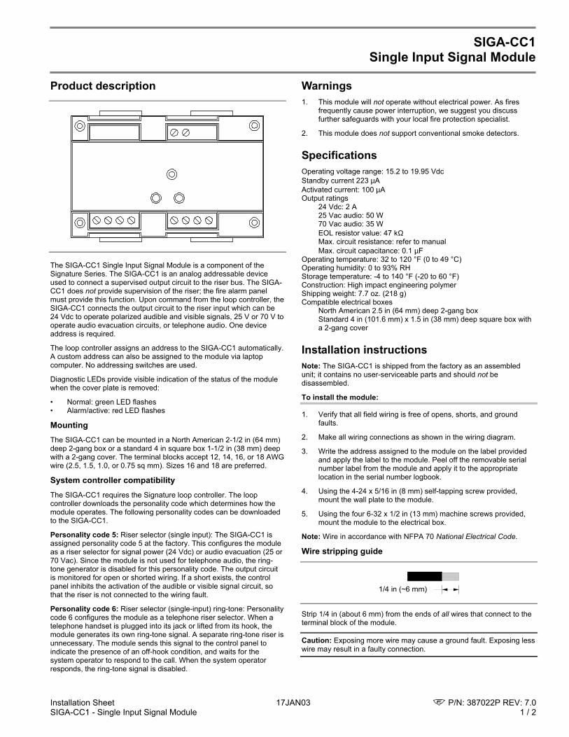
The SIGA-CC1 Single Input Signal Module is a component of theSignature Series. The SIGA-CC1 is an analog addressable deviceused to connect a supervised output circuit to the riser bus. The SIGA-CC1 does not provide supervision of the riser; the fire alarm panelmust provide this function. Upon command from the loop controller, theSIGA-CC1 connects the output circuit to the riser input which can be24 Vdc to operate polarized audible and visible signals, 25 V or 70 V tooperate audio evacuation circuits, or telephone audio. One deviceaddress is required.
The loop controller assigns an address to the SIGA-CC1 automatically.A custom address can also be assigned to the module via laptopcomputer. No addressing switches are used.
Diagnostic LEDs provide visible indication of the status of the modulewhen the cover plate is removed:
• Normal: green LED flashes• Alarm/active: red LED flashes
MountingThe SIGA-CC1 can be mounted in a North American 2-1/2 in (64 mm)deep 2-gang box or a standard 4 in square box 1-1/2 in (38 mm) deepwith a 2-gang cover. The terminal blocks accept 12, 14, 16, or 18 AWGwire (2.5, 1.5, 1.0, or 0.75 sq mm). Sizes 16 and 18 are preferred.
System controller compatibilityThe SIGA-CC1 requires the Signature loop controller. The loopcontroller downloads the personality code which determines how themodule operates. The following personality codes can be downloadedto the SIGA-CC1.
Personality code 5: Riser selector (single input): The SIGA-CC1 isassigned personality code 5 at the factory. This configures the moduleas a riser selector for signal power (24 Vdc) or audio evacuation (25 or70 Vac). Since the module is not used for telephone audio, the ring-tone generator is disabled for this personality code. The output circuitis monitored for open or shorted wiring. If a short exists, the controlpanel inhibits the activation of the audible or visible signal circuit, sothat the riser is not connected to the wiring fault.
Personality code 6: Riser selector (single-input) ring-tone: Personalitycode 6 configures the module as a telephone riser selector. When atelephone handset is plugged into its jack or lifted from its hook, themodule generates its own ring-tone signal. A separate ring-tone riser isunnecessary. The module sends this signal to the control panel toindicate the presence of an off-hook condition, and waits for thesystem operator to respond to the call. When the system operatorresponds, the ring-tone signal is disabled.
Warnings1. This module will not operate without electrical power. As fires
frequently cause power interruption, we suggest you discussfurther safeguards with your local fire protection specialist.
2. This module does not support conventional smoke detectors.
SpecificationsOperating voltage range: 15.2 to 19.95 VdcStandby current 223 µAActivated current: 100 µAOutput ratings
24 Vdc: 2 A25 Vac audio: 50 W70 Vac audio: 35 WEOL resistor value: 47 kΩMax. circuit resistance: refer to manualMax. circuit capacitance: 0.1 µF
Operating temperature: 32 to 120 °F (0 to 49 °C)Operating humidity: 0 to 93% RHStorage temperature: -4 to 140 °F (-20 to 60 °F)Construction: High impact engineering polymerShipping weight: 7.7 oz. (218 g)Compatible electrical boxes
North American 2.5 in (64 mm) deep 2-gang boxStandard 4 in (101.6 mm) x 1.5 in (38 mm) deep square box witha 2-gang cover
Installation instructionsNote: The SIGA-CC1 is shipped from the factory as an assembledunit; it contains no user-serviceable parts and should not bedisassembled.
To install the module:
1. Verify that all field wiring is free of opens, shorts, and groundfaults.
2. Make all wiring connections as shown in the wiring diagram.
3. Write the address assigned to the module on the label providedand apply the label to the module. Peel off the removable serialnumber label from the module and apply it to the appropriatelocation in the serial number logbook.
4. Using the 4-24 x 5/16 in (8 mm) self-tapping screw provided,mount the wall plate to the module.
5. Using the four 6-32 x 1/2 in (13 mm) machine screws provided,mount the module to the electrical box.
Note: Wire in accordance with NFPA 70 National Electrical Code.
Wire stripping guide
1/4 in (~6 mm)
Strip 1/4 in (about 6 mm) from the ends of all wires that connect to theterminal block of the module.
Caution: Exposing more wire may cause a ground fault. Exposing lesswire may result in a faulty connection.
P/N: 387022P REV: 7.0 17JAN03 Installation Sheet2 / 2 SIGA-CC1 - Single Input Signal Module
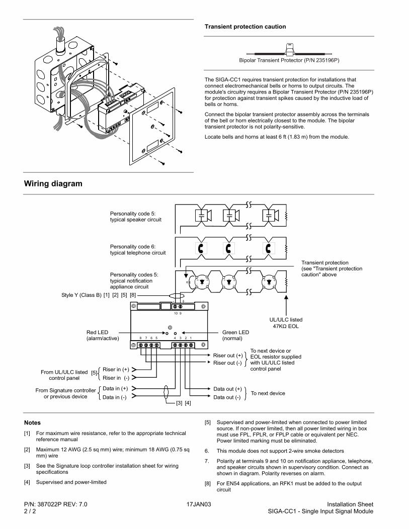
Transient protection caution
Bipolar Transient Protector (P/N 235196P)
The SIGA-CC1 requires transient protection for installations thatconnect electromechanical bells or horns to output circuits. Themodule's circuitry requires a Bipolar Transient Protector (P/N 235196P)for protection against transient spikes caused by the inductive load ofbells or horns.
Connect the bipolar transient protector assembly across the terminalsof the bell or horn electrically closest to the module. The bipolartransient protector is not polarity-sensitive.
Locate bells and horns at least 6 ft (1.83 m) from the module.
Wiring diagram
Data out (-)To next device
Data out (+)Data in (-)
Data in (+)
Riser out (+)
Transient protection(see "Transient protectioncaution" above
UL/ULC listed47K EOLΩ
To next device orEOL resistor suppliedwith UL/ULC listedcontrol panelRiser in (+)
Riser in (-)[5]
Riser out (-)
[4][3]
Personality codes 5:typical notificationappliance circuit
Style Y (Class B)
From Signature controlleror previous device
From UL/ULC listedcontrol panel
[1] [2] [5]
Personality code 6:typical telephone circuit
Personality code 5:typical speaker circuit
[8]
Red LED(alarm/active)
Green LED(normal)12345678
910
Notes[1] For maximum wire resistance, refer to the appropriate technical
reference manual
[2] Maximum 12 AWG (2.5 sq mm) wire; minimum 18 AWG (0.75 sqmm) wire
[3] See the Signature loop controller installation sheet for wiringspecifications
[4] Supervised and power-limited
[5] Supervised and power-limited when connected to power limitedsource. If non-power limited, then all power limited wiring in boxmust use FPL, FPLR, or FPLP cable or equivalent per NEC.Power limited marking must be eliminated.
6. This module does not support 2-wire smoke detectors
7. Polarity at terminals 9 and 10 on notification appliance, telephone,and speaker circuits shown in supervisory condition. Connect asshown in diagram. Polarity reverses on alarm.
[8] For EN54 applications, an RFK1 must be added to the outputcircuit
Installation Sheet 17JAN03 P/N: 3100152 REV: 3.0SIGA-CC1S - Auto-Sync Output Module 1 / 4
SIGA-CC1SAuto-Sync Output Module
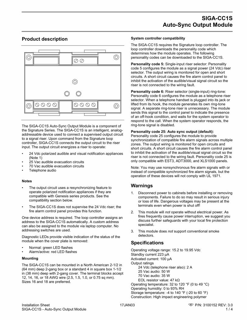
Product description
The SIGA-CC1S Auto-Sync Output Module is a component ofthe Signature Series. The SIGA-CC1S is an intelligent, analog-addressable device used to connect a supervised output circuitto a signal riser. Upon command from the Signature loopcontroller, SIGA-CC1S connects the output circuit to the riserinput. The output circuit energizes a riser to operate:
• 24 Vdc polarized audible and visual notification appliances(Note 1)
• 25 Vac audible evacuation circuits• 70 Vac audible evacuation circuits• Telephone audio
Notes
• The output circuit uses a resynchronizing feature tooperate polarized notification appliances if they arecompatible with Genesis series products. See thecompatibility section below.
• The SIGA-CC1S does not supervise the 24 Vdc riser; thefire alarm control panel provides this function.
One device address is required. The loop controller assigns anaddress to the SIGA-CC1S automatically. A custom addresscan also be assigned to the module via laptop computer. Noaddressing switches are used.
Diagnostic LEDs provide visible indication of the status of themodule when the cover plate is removed:
• Normal: green LED flashes• Alarm/active: red LED flashes
Mounting
The SIGA-CC1S can be mounted in a North American 2-1/2 in(64 mm) deep 2-gang box or a standard 4 in square box 1-1/2in (38 mm) deep with 2-gang cover. The terminal blocks accept12, 14, 16, or 18 AWG wire (2.5, 1.5, 1.0, or 0.75 sq mm).Sizes 16 and 18 are preferred.
System controller compatibility
The SIGA-CC1S requires the Signature loop controller. Theloop controller downloads the personality code whichdetermines how the module operates. The followingpersonality codes can be downloaded to the SIGA-CC1S.
Personality code 5: Single-input riser selector: Personalitycode 5 configures the module as a signal power (24 Vdc) riserselector. The output wiring is monitored for open and shortcircuits. A short circuit causes the fire alarm control panel toinhibit the activation of the audible/visual signal circuit so theriser is not connected to the wiring fault.
Personality code 6: Riser selector (single-input) ring-tone:Personality code 6 configures the module as a telephone riserselector. When a telephone handset is plugged into its jack orlifted from its hook, the module generates its own ring-tonesignal. A separate ring-tone riser is unnecessary. The modulesends this signal to the control panel to indicate the presenceof an off-hook condition, and waits for the system operator torespond to the call. When the system operator responds, thering-tone signal is disabled.
Personality code 25: Auto sync output (default):Personality code 25 configures the module to providesynchronization of compatible fire alarm signals across multiplezones. The output wiring is monitored for open circuits andshort circuits. A short circuit causes the fire alarm control panelto inhibit the activation of the audible/visual signal circuit so theriser is not connected to the wiring fault. Personality code 25 isonly compatible with EST3, ADT3000, and XLS1000 panels.
Note: You may use nonsynchronous fire alarm signals with orinstead of compatible synchronized fire alarm signals, but theoperation of these devices will not comply with UL 1971.
Warnings1. Disconnect power to cabinets before installing or removing
components. Failure to do so may result in serious injuryor loss of life. Dangerous voltages may be present at theterminals even when power is shut off!
2. This module will not operate without electrical power. Asfires frequently cause power interruption, we suggest youdiscuss further safeguards with your local fire protectionspecialist.
3. This module does not support conventional smokedetectors.
SpecificationsOperating voltage range: 15.2 to 19.95 VdcStandby current 223 µAActivated current: 100 µAOutput ratings
24 Vdc (telephone riser also): 2 A25 Vac audio: 50 W70 Vac audio: 35 WEOL resistor value: 47 kΩ
Operating temperature: 32 to 120 °F (0 to 49 °C)Operating humidity: 0 to 93% RHStorage temperature: -4 to 140 °F (-20 to 60 °F)Construction: High impact engineering polymer
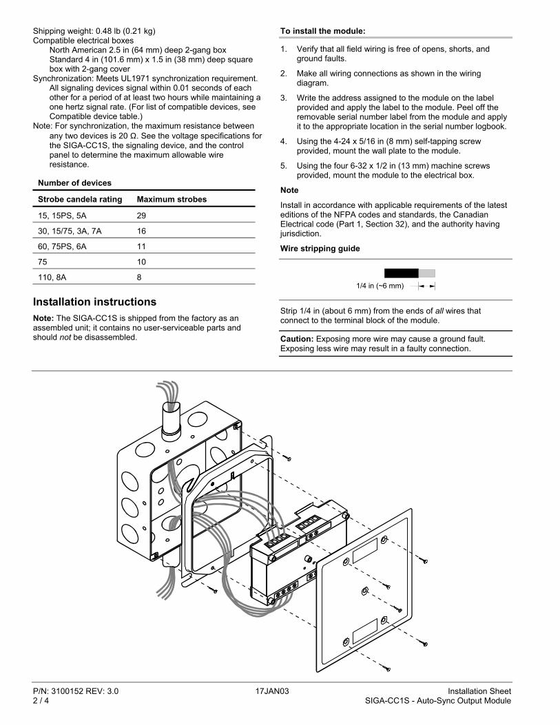
P/N: 3100152 REV: 3.0 17JAN03 Installation Sheet2 / 4 SIGA-CC1S - Auto-Sync Output Module
Shipping weight: 0.48 lb (0.21 kg)Compatible electrical boxes
North American 2.5 in (64 mm) deep 2-gang boxStandard 4 in (101.6 mm) x 1.5 in (38 mm) deep squarebox with 2-gang cover
Synchronization: Meets UL1971 synchronization requirement.All signaling devices signal within 0.01 seconds of eachother for a period of at least two hours while maintaining aone hertz signal rate. (For list of compatible devices, seeCompatible device table.)
Note: For synchronization, the maximum resistance betweenany two devices is 20 Ω. See the voltage specifications forthe SIGA-CC1S, the signaling device, and the controlpanel to determine the maximum allowable wireresistance.
Number of devices
Strobe candela rating Maximum strobes
15, 15PS, 5A 29
30, 15/75, 3A, 7A 16
60, 75PS, 6A 11
75 10
110, 8A 8
Installation instructionsNote: The SIGA-CC1S is shipped from the factory as anassembled unit; it contains no user-serviceable parts andshould not be disassembled.
To install the module:
1. Verify that all field wiring is free of opens, shorts, andground faults.
2. Make all wiring connections as shown in the wiringdiagram.
3. Write the address assigned to the module on the labelprovided and apply the label to the module. Peel off theremovable serial number label from the module and applyit to the appropriate location in the serial number logbook.
4. Using the 4-24 x 5/16 in (8 mm) self-tapping screwprovided, mount the wall plate to the module.
5. Using the four 6-32 x 1/2 in (13 mm) machine screwsprovided, mount the module to the electrical box.
Note
Install in accordance with applicable requirements of the latesteditions of the NFPA codes and standards, the CanadianElectrical code (Part 1, Section 32), and the authority havingjurisdiction.
Wire stripping guide
1/4 in (~6 mm)
Strip 1/4 in (about 6 mm) from the ends of all wires thatconnect to the terminal block of the module.
Caution: Exposing more wire may cause a ground fault.Exposing less wire may result in a faulty connection.
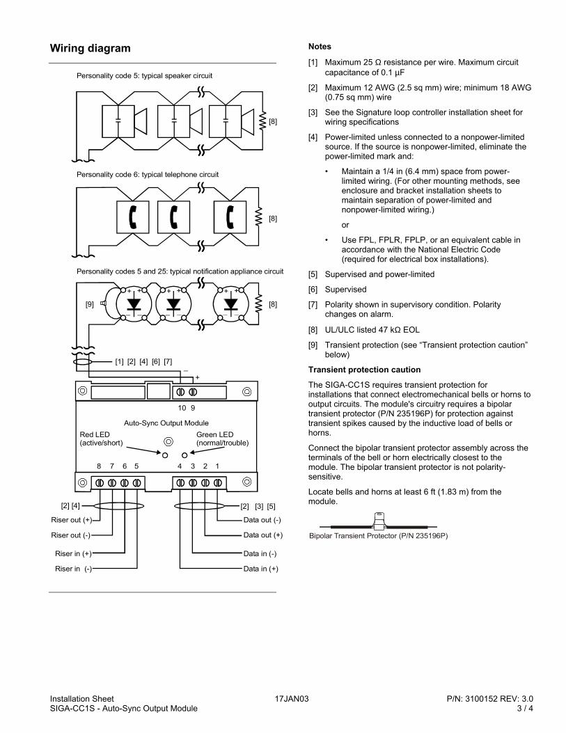
Installation Sheet 17JAN03 P/N: 3100152 REV: 3.0SIGA-CC1S - Auto-Sync Output Module 3 / 4
Wiring diagram
12345678
Red LED(active/short)
Green LED(normal/trouble)
910
Data out (-)
Data out (+)
Data in (-)
Data in (+)
Riser out (+)
Riser in (+)
Riser in (-)
[4] [2]
Riser out (-)
Auto-Sync Output Module
[5][3][2]
+ +
_ _
+ +
_ _
+ +
_ _
Personality codes 5 and 25: typical notification appliance circuit
[1] [2] [4]
Personality code 6: typical telephone circuit
Personality code 5: typical speaker circuit
[6] [7]
+_
[8]
[8]
[8][9]
Notes
[1] Maximum 25 Ω resistance per wire. Maximum circuitcapacitance of 0.1 µF
[2] Maximum 12 AWG (2.5 sq mm) wire; minimum 18 AWG(0.75 sq mm) wire
[3] See the Signature loop controller installation sheet forwiring specifications
[4] Power-limited unless connected to a nonpower-limitedsource. If the source is nonpower-limited, eliminate thepower-limited mark and:
• Maintain a 1/4 in (6.4 mm) space from power-limited wiring. (For other mounting methods, seeenclosure and bracket installation sheets tomaintain separation of power-limited andnonpower-limited wiring.)
or
• Use FPL, FPLR, FPLP, or an equivalent cable inaccordance with the National Electric Code(required for electrical box installations).
[5] Supervised and power-limited
[6] Supervised
[7] Polarity shown in supervisory condition. Polaritychanges on alarm.
[8] UL/ULC listed 47 kΩ EOL
[9] Transient protection (see “Transient protection caution”below)
Transient protection caution
The SIGA-CC1S requires transient protection forinstallations that connect electromechanical bells or horns tooutput circuits. The module's circuitry requires a bipolartransient protector (P/N 235196P) for protection againsttransient spikes caused by the inductive load of bells orhorns.
Connect the bipolar transient protector assembly across theterminals of the bell or horn electrically closest to themodule. The bipolar transient protector is not polarity-sensitive.
Locate bells and horns at least 6 ft (1.83 m) from themodule.
Bipolar Transient Protector (P/N 235196P)
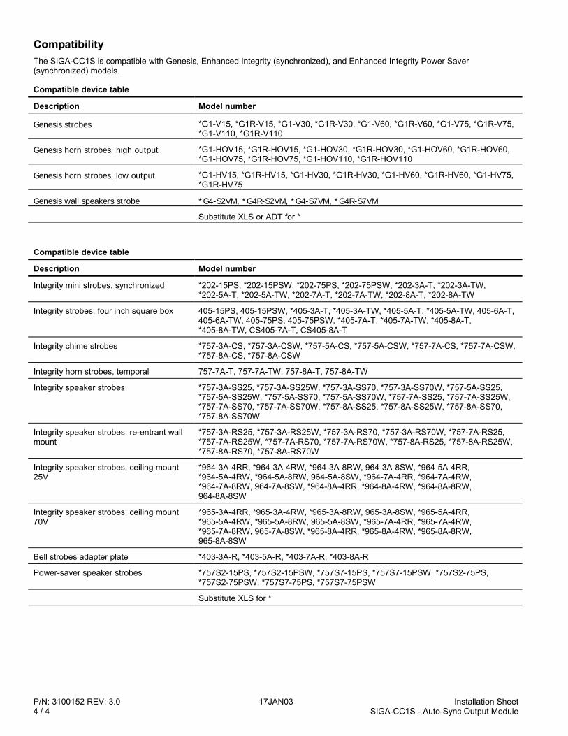
P/N: 3100152 REV: 3.0 17JAN03 Installation Sheet4 / 4 SIGA-CC1S - Auto-Sync Output Module
CompatibilityThe SIGA-CC1S is compatible with Genesis, Enhanced Integrity (synchronized), and Enhanced Integrity Power Saver(synchronized) models.
Compatible device table
Description Model number
Genesis strobes *G1-V15, *G1R-V15, *G1-V30, *G1R-V30, *G1-V60, *G1R-V60, *G1-V75, *G1R-V75,*G1-V110, *G1R-V110
Genesis horn strobes, high output *G1-HOV15, *G1R-HOV15, *G1-HOV30, *G1R-HOV30, *G1-HOV60, *G1R-HOV60,*G1-HOV75, *G1R-HOV75, *G1-HOV110, *G1R-HOV110
Genesis horn strobes, low output *G1-HV15, *G1R-HV15, *G1-HV30, *G1R-HV30, *G1-HV60, *G1R-HV60, *G1-HV75,*G1R-HV75
Genesis wall speakers strobe *G4-S2VM, *G4R-S2VM, *G4-S7VM, *G4R-S7VM
Substitute XLS or ADT for *
Compatible device table
Description Model number
Integrity mini strobes, synchronized *202-15PS, *202-15PSW, *202-75PS, *202-75PSW, *202-3A-T, *202-3A-TW,*202-5A-T, *202-5A-TW, *202-7A-T, *202-7A-TW, *202-8A-T, *202-8A-TW
Integrity strobes, four inch square box 405-15PS, 405-15PSW, *405-3A-T, *405-3A-TW, *405-5A-T, *405-5A-TW, 405-6A-T,405-6A-TW, 405-75PS, 405-75PSW, *405-7A-T, *405-7A-TW, *405-8A-T,*405-8A-TW, CS405-7A-T, CS405-8A-T
Integrity chime strobes *757-3A-CS, *757-3A-CSW, *757-5A-CS, *757-5A-CSW, *757-7A-CS, *757-7A-CSW,*757-8A-CS, *757-8A-CSW
Integrity horn strobes, temporal 757-7A-T, 757-7A-TW, 757-8A-T, 757-8A-TW
Integrity speaker strobes *757-3A-SS25, *757-3A-SS25W, *757-3A-SS70, *757-3A-SS70W, *757-5A-SS25,*757-5A-SS25W, *757-5A-SS70, *757-5A-SS70W, *757-7A-SS25, *757-7A-SS25W,*757-7A-SS70, *757-7A-SS70W, *757-8A-SS25, *757-8A-SS25W, *757-8A-SS70,*757-8A-SS70W
Integrity speaker strobes, re-entrant wallmount
*757-3A-RS25, *757-3A-RS25W, *757-3A-RS70, *757-3A-RS70W, *757-7A-RS25,*757-7A-RS25W, *757-7A-RS70, *757-7A-RS70W, *757-8A-RS25, *757-8A-RS25W,*757-8A-RS70, *757-8A-RS70W
Integrity speaker strobes, ceiling mount25V
*964-3A-4RR, *964-3A-4RW, *964-3A-8RW, 964-3A-8SW, *964-5A-4RR,*964-5A-4RW, *964-5A-8RW, 964-5A-8SW, *964-7A-4RR, *964-7A-4RW,*964-7A-8RW, 964-7A-8SW, *964-8A-4RR, *964-8A-4RW, *964-8A-8RW,964-8A-8SW
Integrity speaker strobes, ceiling mount70V
*965-3A-4RR, *965-3A-4RW, *965-3A-8RW, 965-3A-8SW, *965-5A-4RR,*965-5A-4RW, *965-5A-8RW, 965-5A-8SW, *965-7A-4RR, *965-7A-4RW,*965-7A-8RW, 965-7A-8SW, *965-8A-4RR, *965-8A-4RW, *965-8A-8RW,965-8A-8SW
Bell strobes adapter plate *403-3A-R, *403-5A-R, *403-7A-R, *403-8A-R
Power-saver speaker strobes *757S2-15PS, *757S2-15PSW, *757S7-15PS, *757S7-15PSW, *757S2-75PS,*757S2-75PSW, *757S7-75PS, *757S7-75PSW
Substitute XLS for *
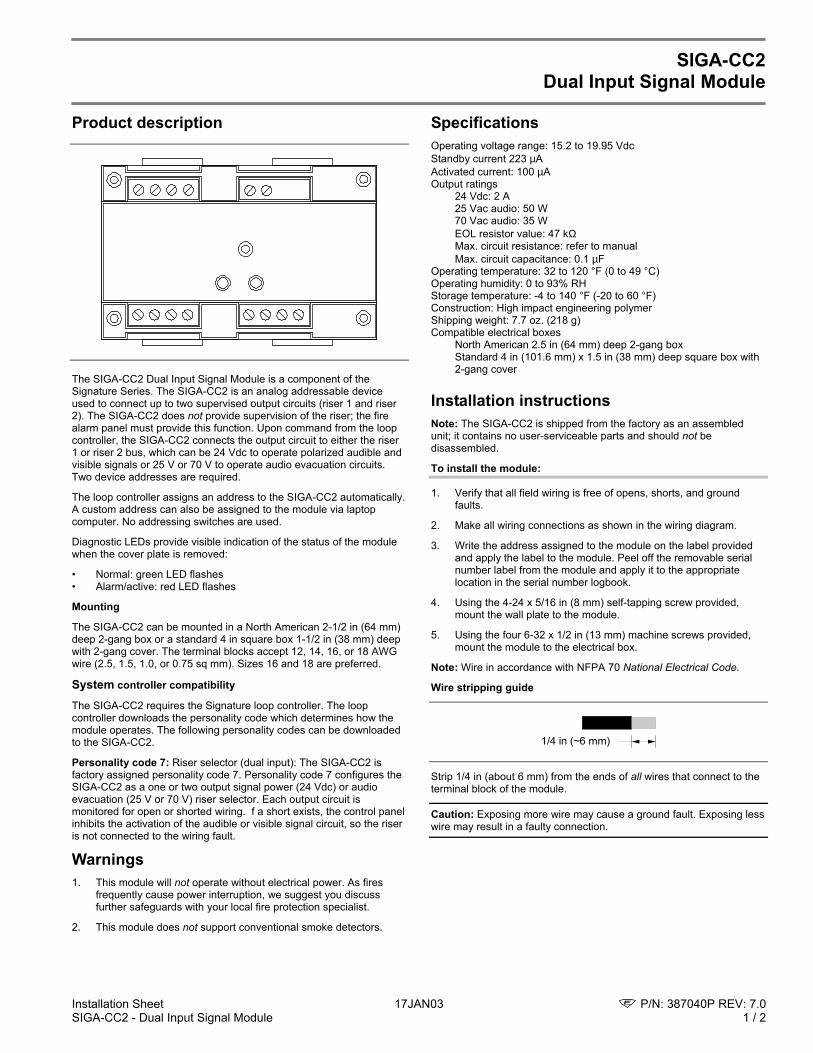
Installation Sheet 17JAN03 P/N: 387040P REV: 7.0SIGA-CC2 - Dual Input Signal Module 1 / 2
SIGA-CC2Dual Input Signal Module
Product description
The SIGA-CC2 Dual Input Signal Module is a component of theSignature Series. The SIGA-CC2 is an analog addressable deviceused to connect up to two supervised output circuits (riser 1 and riser2). The SIGA-CC2 does not provide supervision of the riser; the firealarm panel must provide this function. Upon command from the loopcontroller, the SIGA-CC2 connects the output circuit to either the riser1 or riser 2 bus, which can be 24 Vdc to operate polarized audible andvisible signals or 25 V or 70 V to operate audio evacuation circuits.Two device addresses are required.
The loop controller assigns an address to the SIGA-CC2 automatically.A custom address can also be assigned to the module via laptopcomputer. No addressing switches are used.
Diagnostic LEDs provide visible indication of the status of the modulewhen the cover plate is removed:
• Normal: green LED flashes• Alarm/active: red LED flashes
Mounting
The SIGA-CC2 can be mounted in a North American 2-1/2 in (64 mm)deep 2-gang box or a standard 4 in square box 1-1/2 in (38 mm) deepwith 2-gang cover. The terminal blocks accept 12, 14, 16, or 18 AWGwire (2.5, 1.5, 1.0, or 0.75 sq mm). Sizes 16 and 18 are preferred.
System controller compatibility
The SIGA-CC2 requires the Signature loop controller. The loopcontroller downloads the personality code which determines how themodule operates. The following personality codes can be downloadedto the SIGA-CC2.
Personality code 7: Riser selector (dual input): The SIGA-CC2 isfactory assigned personality code 7. Personality code 7 configures theSIGA-CC2 as a one or two output signal power (24 Vdc) or audioevacuation (25 V or 70 V) riser selector. Each output circuit ismonitored for open or shorted wiring. f a short exists, the control panelinhibits the activation of the audible or visible signal circuit, so the riseris not connected to the wiring fault.
Warnings1. This module will not operate without electrical power. As fires
frequently cause power interruption, we suggest you discussfurther safeguards with your local fire protection specialist.
2. This module does not support conventional smoke detectors.
SpecificationsOperating voltage range: 15.2 to 19.95 VdcStandby current 223 µAActivated current: 100 µAOutput ratings
24 Vdc: 2 A25 Vac audio: 50 W70 Vac audio: 35 WEOL resistor value: 47 kΩMax. circuit resistance: refer to manualMax. circuit capacitance: 0.1 µF
Operating temperature: 32 to 120 °F (0 to 49 °C)Operating humidity: 0 to 93% RHStorage temperature: -4 to 140 °F (-20 to 60 °F)Construction: High impact engineering polymerShipping weight: 7.7 oz. (218 g)Compatible electrical boxes
North American 2.5 in (64 mm) deep 2-gang boxStandard 4 in (101.6 mm) x 1.5 in (38 mm) deep square box with2-gang cover
Installation instructionsNote: The SIGA-CC2 is shipped from the factory as an assembledunit; it contains no user-serviceable parts and should not bedisassembled.
To install the module:
1. Verify that all field wiring is free of opens, shorts, and groundfaults.
2. Make all wiring connections as shown in the wiring diagram.
3. Write the address assigned to the module on the label providedand apply the label to the module. Peel off the removable serialnumber label from the module and apply it to the appropriatelocation in the serial number logbook.
4. Using the 4-24 x 5/16 in (8 mm) self-tapping screw provided,mount the wall plate to the module.
5. Using the four 6-32 x 1/2 in (13 mm) machine screws provided,mount the module to the electrical box.
Note: Wire in accordance with NFPA 70 National Electrical Code.
Wire stripping guide
1/4 in (~6 mm)
Strip 1/4 in (about 6 mm) from the ends of all wires that connect to theterminal block of the module.
Caution: Exposing more wire may cause a ground fault. Exposing lesswire may result in a faulty connection.
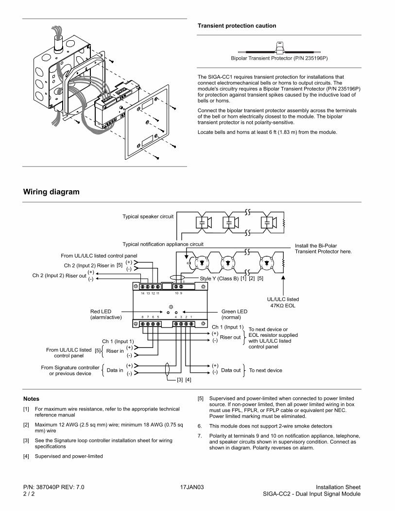
P/N: 387040P REV: 7.0 17JAN03 Installation Sheet2 / 2 SIGA-CC2 - Dual Input Signal Module
Transient protection caution
Bipolar Transient Protector (P/N 235196P)
The SIGA-CC1 requires transient protection for installations thatconnect electromechanical bells or horns to output circuits. Themodule's circuitry requires a Bipolar Transient Protector (P/N 235196P)for protection against transient spikes caused by the inductive load ofbells or horns.
Connect the bipolar transient protector assembly across the terminalsof the bell or horn electrically closest to the module. The bipolartransient protector is not polarity-sensitive.
Locate bells and horns at least 6 ft (1.83 m) from the module.
Wiring diagram
To next device(-) (-)(+) (+)
Install the Bi-Polar Transient Protector here.
UL/ULC listed47K EOLΩ
To next device orEOL resistor suppliedwith UL/ULC listedcontrol panel (+)
(+)
(+)
(+)
(-)
(-)
(-)
(-)
[5]
[4][3]
Typical notification appliance circuit
Style Y (Class B)
From Signature controlleror previous device
From UL/ULC listedcontrol panel
From UL/ULC listed control panel
[1] [2] [5]
Red LED(alarm/active)
Green LED(normal)12345
11
6
12
7
13
8
14 910
Typical speaker circuit
Riser in
Ch 2 (Input 2) Riser in
Riser out
Riser out
Ch 1 (Input 1)
Ch 1 (Input 1)
Ch 2 (Input 2)
Data in Data out
[5]
Notes[1] For maximum wire resistance, refer to the appropriate technical
reference manual
[2] Maximum 12 AWG (2.5 sq mm) wire; minimum 18 AWG (0.75 sqmm) wire
[3] See the Signature loop controller installation sheet for wiringspecifications
[4] Supervised and power-limited
[5] Supervised and power-limited when connected to power limitedsource. If non-power limited, then all power limited wiring in boxmust use FPL, FPLR, or FPLP cable or equivalent per NEC.Power limited marking must be eliminated.
6. This module does not support 2-wire smoke detectors
7. Polarity at terminals 9 and 10 on notification appliance, telephone,and speaker circuits shown in supervisory condition. Connect asshown in diagram. Polarity reverses on alarm.
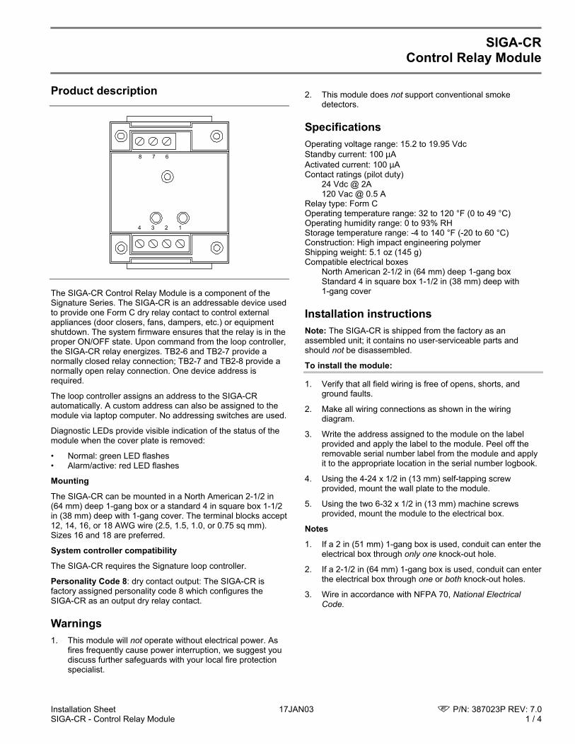
Installation Sheet 17JAN03 P/N: 387023P REV: 7.0SIGA-CR - Control Relay Module 1 / 4
SIGA-CRControl Relay Module
Product description
1234
678
The SIGA-CR Control Relay Module is a component of theSignature Series. The SIGA-CR is an addressable device usedto provide one Form C dry relay contact to control externalappliances (door closers, fans, dampers, etc.) or equipmentshutdown. The system firmware ensures that the relay is in theproper ON/OFF state. Upon command from the loop controller,the SIGA-CR relay energizes. TB2-6 and TB2-7 provide anormally closed relay connection; TB2-7 and TB2-8 provide anormally open relay connection. One device address isrequired.
The loop controller assigns an address to the SIGA-CRautomatically. A custom address can also be assigned to themodule via laptop computer. No addressing switches are used.
Diagnostic LEDs provide visible indication of the status of themodule when the cover plate is removed:
• Normal: green LED flashes• Alarm/active: red LED flashes
Mounting
The SIGA-CR can be mounted in a North American 2-1/2 in(64 mm) deep 1-gang box or a standard 4 in square box 1-1/2in (38 mm) deep with 1-gang cover. The terminal blocks accept12, 14, 16, or 18 AWG wire (2.5, 1.5, 1.0, or 0.75 sq mm).Sizes 16 and 18 are preferred.
System controller compatibility
The SIGA-CR requires the Signature loop controller.
Personality Code 8: dry contact output: The SIGA-CR isfactory assigned personality code 8 which configures theSIGA-CR as an output dry relay contact.
Warnings1. This module will not operate without electrical power. As
fires frequently cause power interruption, we suggest youdiscuss further safeguards with your local fire protectionspecialist.
2. This module does not support conventional smokedetectors.
SpecificationsOperating voltage range: 15.2 to 19.95 VdcStandby current: 100 µAActivated current: 100 µAContact ratings (pilot duty)
24 Vdc @ 2A120 Vac @ 0.5 A
Relay type: Form COperating temperature range: 32 to 120 °F (0 to 49 °C)Operating humidity range: 0 to 93% RHStorage temperature range: -4 to 140 °F (-20 to 60 °C)Construction: High impact engineering polymerShipping weight: 5.1 oz (145 g)Compatible electrical boxes
North American 2-1/2 in (64 mm) deep 1-gang boxStandard 4 in square box 1-1/2 in (38 mm) deep with1-gang cover
Installation instructionsNote: The SIGA-CR is shipped from the factory as anassembled unit; it contains no user-serviceable parts andshould not be disassembled.
To install the module:
1. Verify that all field wiring is free of opens, shorts, andground faults.
2. Make all wiring connections as shown in the wiringdiagram.
3. Write the address assigned to the module on the labelprovided and apply the label to the module. Peel off theremovable serial number label from the module and applyit to the appropriate location in the serial number logbook.
4. Using the 4-24 x 1/2 in (13 mm) self-tapping screwprovided, mount the wall plate to the module.
5. Using the two 6-32 x 1/2 in (13 mm) machine screwsprovided, mount the module to the electrical box.
Notes
1. If a 2 in (51 mm) 1-gang box is used, conduit can enter theelectrical box through only one knock-out hole.
2. If a 2-1/2 in (64 mm) 1-gang box is used, conduit can enterthe electrical box through one or both knock-out holes.
3. Wire in accordance with NFPA 70, National ElectricalCode.
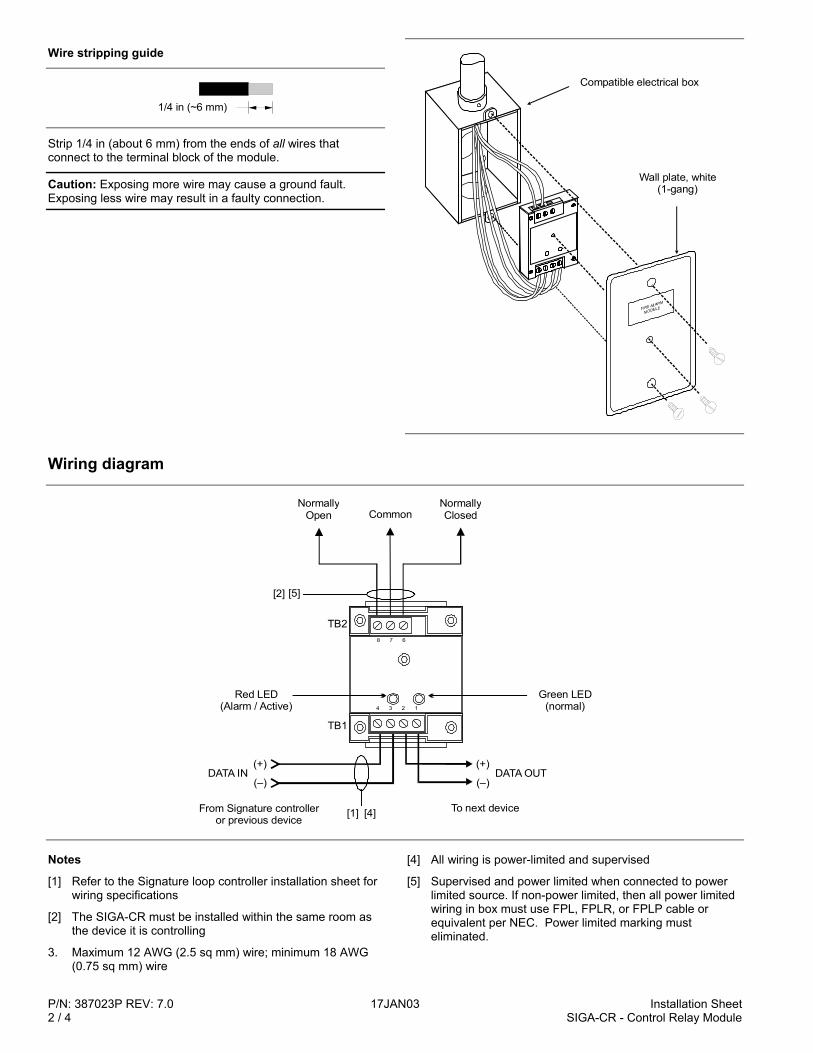
P/N: 387023P REV: 7.0 17JAN03 Installation Sheet2 / 4 SIGA-CR - Control Relay Module
Wire stripping guide
1/4 in (~6 mm)
Strip 1/4 in (about 6 mm) from the ends of all wires thatconnect to the terminal block of the module.
Caution: Exposing more wire may cause a ground fault.Exposing less wire may result in a faulty connection.
Compatible electrical box
Wall plate, white(1-gang)
Wiring diagram
(+)
(–)DATA OUT
Red LED(Alarm / Active)
TB2
TB1
Green LED(normal)
(+)
(–)
From Signature controlleror previous device
[1] [4]
[2] [5]
To next device
NormallyOpen
NormallyClosedCommon
DATA IN
1234
678
Notes
[1] Refer to the Signature loop controller installation sheet forwiring specifications
[2] The SIGA-CR must be installed within the same room asthe device it is controlling
3. Maximum 12 AWG (2.5 sq mm) wire; minimum 18 AWG(0.75 sq mm) wire
[4] All wiring is power-limited and supervised
[5] Supervised and power limited when connected to powerlimited source. If non-power limited, then all power limitedwiring in box must use FPL, FPLR, or FPLP cable orequivalent per NEC. Power limited marking musteliminated.
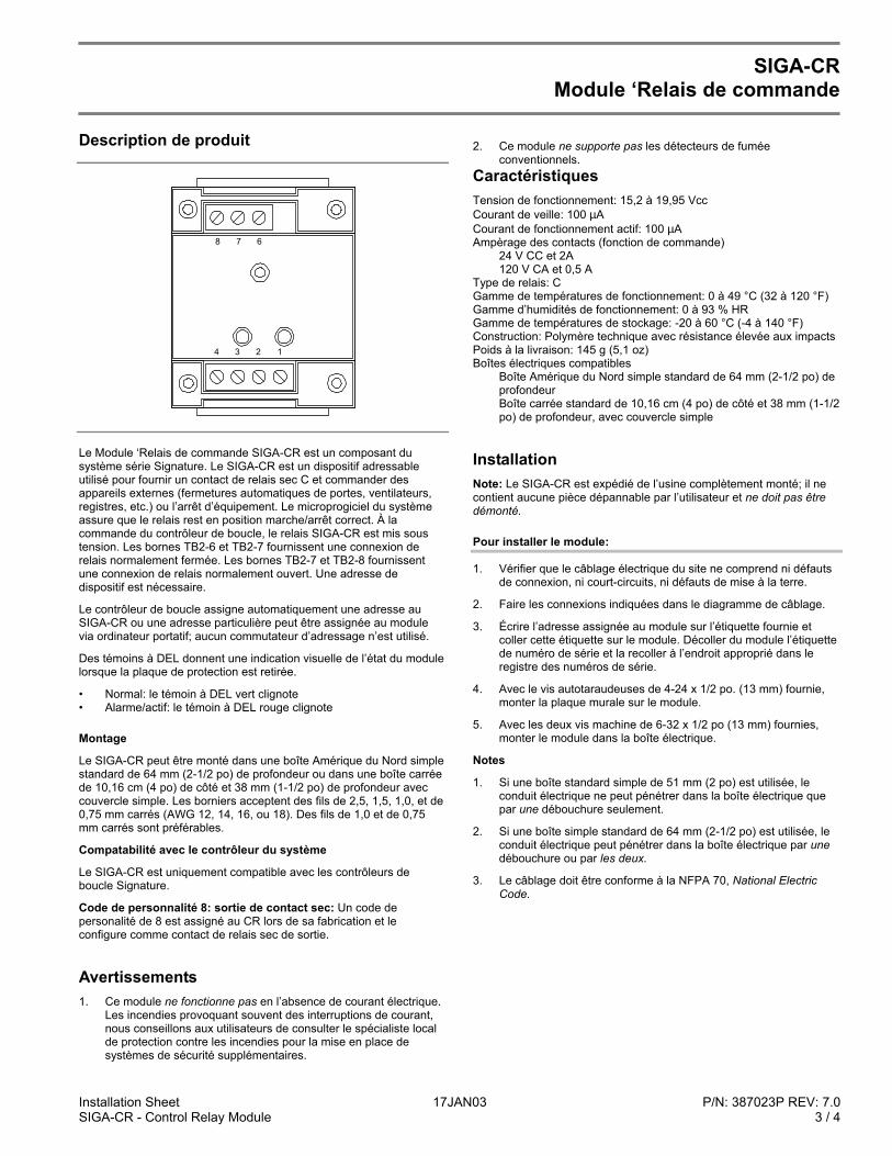
Installation Sheet 17JAN03 P/N: 387023P REV: 7.0SIGA-CR - Control Relay Module 3 / 4
SIGA-CRModule ‘Relais de commande
Description de produit
1234
678
Le Module ‘Relais de commande SIGA-CR est un composant dusystème série Signature. Le SIGA-CR est un dispositif adressableutilisé pour fournir un contact de relais sec C et commander desappareils externes (fermetures automatiques de portes, ventilateurs,registres, etc.) ou l’arrêt d’équipement. Le microprogiciel du systèmeassure que le relais rest en position marche/arrêt correct. À lacommande du contrôleur de boucle, le relais SIGA-CR est mis soustension. Les bornes TB2-6 et TB2-7 fournissent une connexion derelais normalement fermée. Les bornes TB2-7 et TB2-8 fournissentune connexion de relais normalement ouvert. Une adresse dedispositif est nécessaire.
Le contrôleur de boucle assigne automatiquement une adresse auSIGA-CR ou une adresse particulière peut être assignée au modulevia ordinateur portatif; aucun commutateur d’adressage n’est utilisé.
Des témoins à DEL donnent une indication visuelle de l’état du modulelorsque la plaque de protection est retirée.
• Normal: le témoin à DEL vert clignote• Alarme/actif: le témoin à DEL rouge clignote
Montage
Le SIGA-CR peut être monté dans une boîte Amérique du Nord simplestandard de 64 mm (2-1/2 po) de profondeur ou dans une boîte carréede 10,16 cm (4 po) de côté et 38 mm (1-1/2 po) de profondeur aveccouvercle simple. Les borniers acceptent des fils de 2,5, 1,5, 1,0, et de0,75 mm carrés (AWG 12, 14, 16, ou 18). Des fils de 1,0 et de 0,75mm carrés sont préférables.
Compatabilité avec le contrôleur du système
Le SIGA-CR est uniquement compatible avec les contrôleurs deboucle Signature.
Code de personnalité 8: sortie de contact sec: Un code depersonalité de 8 est assigné au CR lors de sa fabrication et leconfigure comme contact de relais sec de sortie.
Avertissements1. Ce module ne fonctionne pas en l’absence de courant électrique.
Les incendies provoquant souvent des interruptions de courant,nous conseillons aux utilisateurs de consulter le spécialiste localde protection contre les incendies pour la mise en place desystèmes de sécurité supplémentaires.
2. Ce module ne supporte pas les détecteurs de fuméeconventionnels.
CaractéristiquesTension de fonctionnement: 15,2 à 19,95 VccCourant de veille: 100 µACourant de fonctionnement actif: 100 µAAmpèrage des contacts (fonction de commande)
24 V CC et 2A120 V CA et 0,5 A
Type de relais: CGamme de températures de fonctionnement: 0 à 49 °C (32 à 120 °F)Gamme d’humidités de fonctionnement: 0 à 93 % HRGamme de températures de stockage: -20 à 60 °C (-4 à 140 °F)Construction: Polymère technique avec résistance élevée aux impactsPoids à la livraison: 145 g (5,1 oz)Boîtes électriques compatibles
Boîte Amérique du Nord simple standard de 64 mm (2-1/2 po) deprofondeurBoîte carrée standard de 10,16 cm (4 po) de côté et 38 mm (1-1/2po) de profondeur, avec couvercle simple
InstallationNote: Le SIGA-CR est expédié de l’usine complètement monté; il necontient aucune pièce dépannable par l’utilisateur et ne doit pas êtredémonté.
Pour installer le module:
1. Vérifier que le câblage électrique du site ne comprend ni défautsde connexion, ni court-circuits, ni défauts de mise à la terre.
2. Faire les connexions indiquées dans le diagramme de câblage.
3. Écrire l’adresse assignée au module sur l’étiquette fournie etcoller cette étiquette sur le module. Décoller du module l’étiquettede numéro de série et la recoller à l’endroit approprié dans leregistre des numéros de série.
4. Avec le vis autotaraudeuses de 4-24 x 1/2 po. (13 mm) fournie,monter la plaque murale sur le module.
5. Avec les deux vis machine de 6-32 x 1/2 po (13 mm) fournies,monter le module dans la boîte électrique.
Notes
1. Si une boîte standard simple de 51 mm (2 po) est utilisée, leconduit électrique ne peut pénétrer dans la boîte électrique quepar une débouchure seulement.
2. Si une boîte simple standard de 64 mm (2-1/2 po) est utilisée, leconduit électrique peut pénétrer dans la boîte électrique par unedébouchure ou par les deux.
3. Le câblage doit être conforme à la NFPA 70, National ElectricCode.
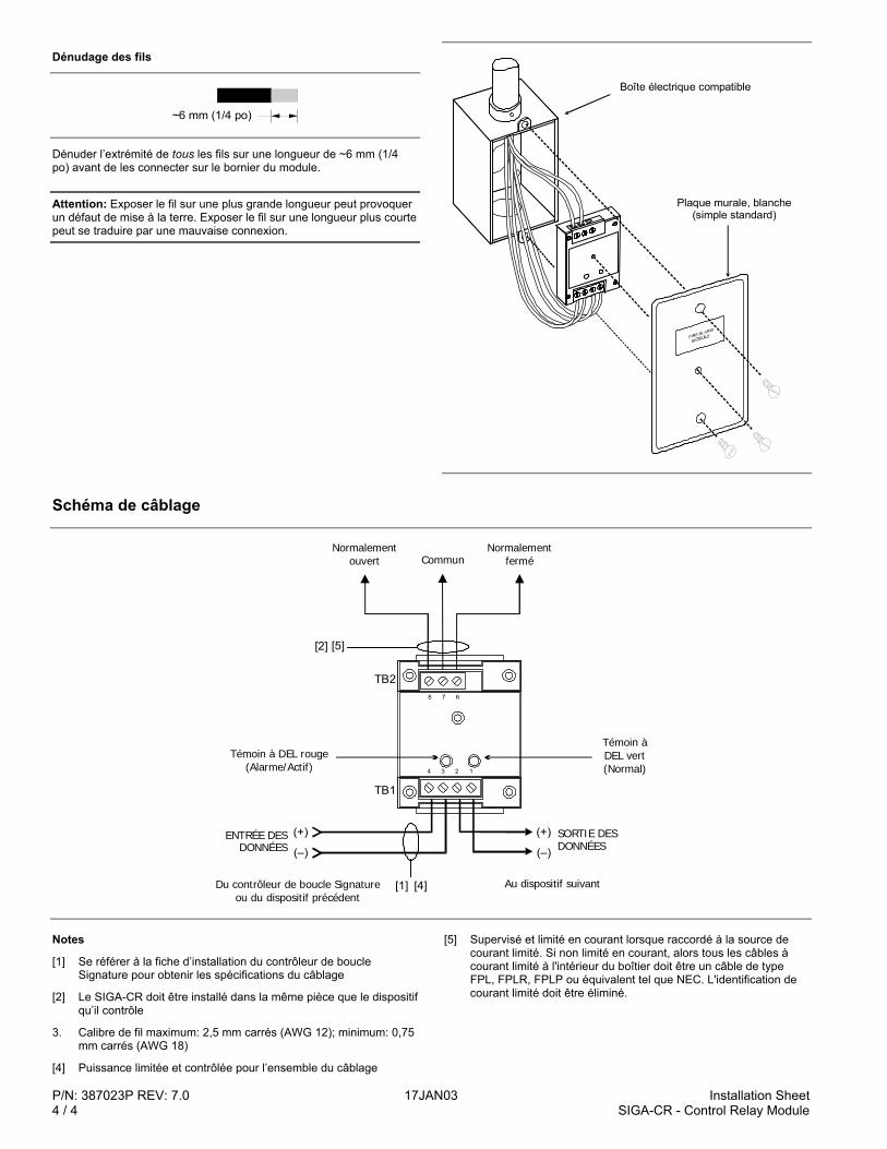
P/N: 387023P REV: 7.0 17JAN03 Installation Sheet4 / 4 SIGA-CR - Control Relay Module
Dénudage des fils
~6 mm 1/4 po ( )
Dénuder l’extrémité de tous les fils sur une longueur de ~6 mm (1/4po) avant de les connecter sur le bornier du module.
Attention: Exposer le fil sur une plus grande longueur peut provoquerun défaut de mise à la terre. Exposer le fil sur une longueur plus courtepeut se traduire par une mauvaise connexion.
Plaque murale, blanche (simple standard)
Boîte électrique compatible
Schéma de câblage
(+)
(–)
SORTIE DES DONNÉES
Témoin à DEL rouge (Alarme/Actif)
TB2
TB1
Témoin àDEL vert(Normal)
(+)
(–)
Du contrôleur de boucle Signature ou du dispositif précédent
[1] [4]
[2] [5]
Au dispositif suivant
Normalement ouvert
Normalement ferméCommun
ENTRÉE DES DONNÉES
1234
678
Notes
[1] Se référer à la fiche d’installation du contrôleur de boucleSignature pour obtenir les spécifications du câblage
[2] Le SIGA-CR doit être installé dans la même pièce que le dispositifqu’il contrôle
3. Calibre de fil maximum: 2,5 mm carrés (AWG 12); minimum: 0,75mm carrés (AWG 18)
[4] Puissance limitée et contrôlée pour l’ensemble du câblage
[5] Supervisé et limité en courant lorsque raccordé à la source decourant limité. Si non limité en courant, alors tous les câbles àcourant limité à l'intérieur du boîtier doit être un câble de typeFPL, FPLR, FPLP ou équivalent tel que NEC. L'identification decourant limité doit être éliminé.
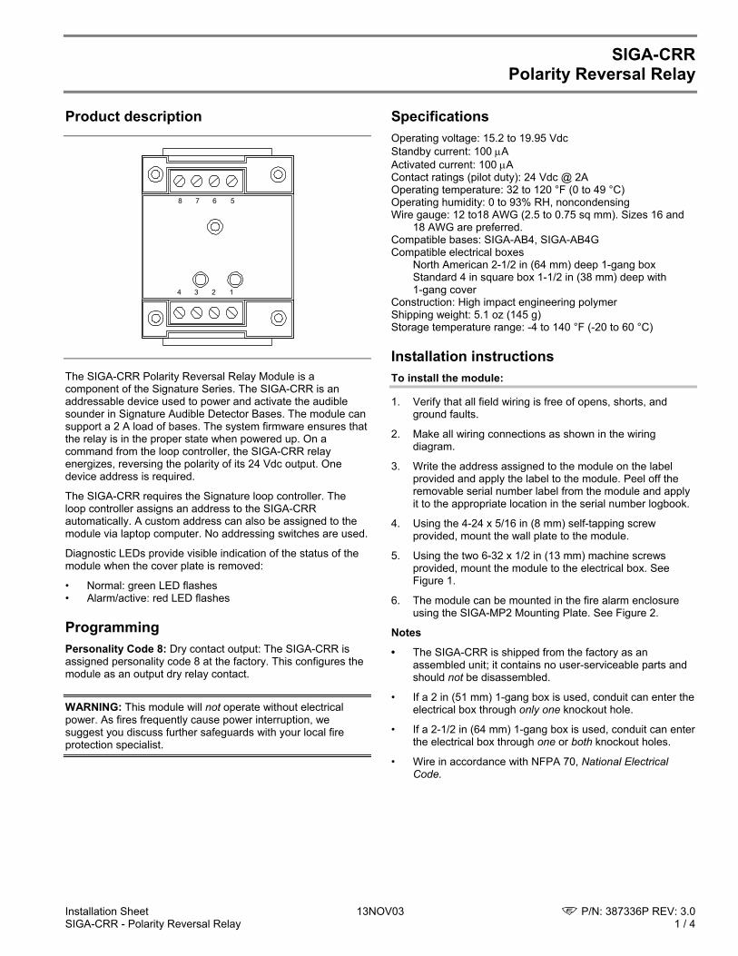
Installation Sheet 13NOV03 P/N: 387336P REV: 3.0 SIGA-CRR - Polarity Reversal Relay 1 / 4
SIGA-CRR Polarity Reversal Relay
Product description
1234
5678
The SIGA-CRR Polarity Reversal Relay Module is a component of the Signature Series. The SIGA-CRR is an addressable device used to power and activate the audible sounder in Signature Audible Detector Bases. The module can support a 2 A load of bases. The system firmware ensures that the relay is in the proper state when powered up. On a command from the loop controller, the SIGA-CRR relay energizes, reversing the polarity of its 24 Vdc output. One device address is required.
The SIGA-CRR requires the Signature loop controller. The loop controller assigns an address to the SIGA-CRR automatically. A custom address can also be assigned to the module via laptop computer. No addressing switches are used.
Diagnostic LEDs provide visible indication of the status of the module when the cover plate is removed:
• Normal: green LED flashes • Alarm/active: red LED flashes
Programming Personality Code 8: Dry contact output: The SIGA-CRR is assigned personality code 8 at the factory. This configures the module as an output dry relay contact.
WARNING: This module will not operate without electrical power. As fires frequently cause power interruption, we suggest you discuss further safeguards with your local fire protection specialist.
Specifications Operating voltage: 15.2 to 19.95 Vdc Standby current: 100 µA Activated current: 100 µA Contact ratings (pilot duty): 24 Vdc @ 2A Operating temperature: 32 to 120 °F (0 to 49 °C) Operating humidity: 0 to 93% RH, noncondensing Wire gauge: 12 to18 AWG (2.5 to 0.75 sq mm). Sizes 16 and
18 AWG are preferred. Compatible bases: SIGA-AB4, SIGA-AB4G Compatible electrical boxes North American 2-1/2 in (64 mm) deep 1-gang box Standard 4 in square box 1-1/2 in (38 mm) deep with
1-gang cover Construction: High impact engineering polymer Shipping weight: 5.1 oz (145 g) Storage temperature range: -4 to 140 °F (-20 to 60 °C)
Installation instructions To install the module:
1. Verify that all field wiring is free of opens, shorts, and ground faults.
2. Make all wiring connections as shown in the wiring diagram.
3. Write the address assigned to the module on the label provided and apply the label to the module. Peel off the removable serial number label from the module and apply it to the appropriate location in the serial number logbook.
4. Using the 4-24 x 5/16 in (8 mm) self-tapping screw provided, mount the wall plate to the module.
5. Using the two 6-32 x 1/2 in (13 mm) machine screws provided, mount the module to the electrical box. See Figure 1.
6. The module can be mounted in the fire alarm enclosure using the SIGA-MP2 Mounting Plate. See Figure 2.
Notes
• The SIGA-CRR is shipped from the factory as an assembled unit; it contains no user-serviceable parts and should not be disassembled.
• If a 2 in (51 mm) 1-gang box is used, conduit can enter the electrical box through only one knockout hole.
• If a 2-1/2 in (64 mm) 1-gang box is used, conduit can enter the electrical box through one or both knockout holes.
• Wire in accordance with NFPA 70, National Electrical Code.
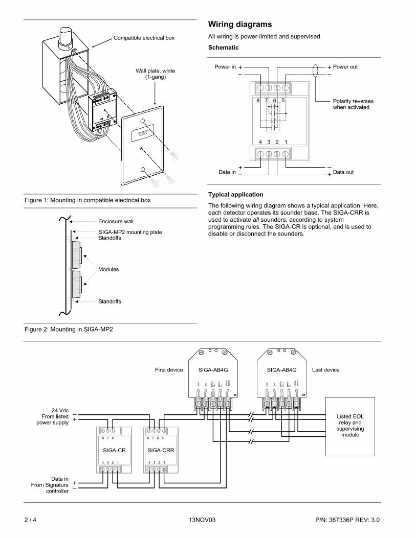
2 / 4 13NOV03 P/N: 387336P REV: 3.0
Compatible electrical box
Wall plate, white (1-gang)
Figure 1: Mounting in compatible electrical box
Enclosure wall
Standoffs
Modules
SIGA-MP2 mounting plateStandoffs
Figure 2: Mounting in SIGA-MP2
Wiring diagrams All wiring is power-limited and supervised.
Schematic
Power in Power out
Polarity reverseswhen activated
8 7 6 5
4 3 2 1
+–
+–
+–
+–Data in Data out
Typical application
The following wiring diagram shows a typical application. Here, each detector operates its sounder base. The SIGA-CRR is used to activate all sounders, according to system programming rules. The SIGA-CR is optional, and is used to disable or disconnect the sounders.
SIG
+
SIG
-
DAT
A+IN
/OU
T
SIGA-AB4G
Data inFrom Signature
controller
–+
24 VdcFrom listed
power supply
+–
Listed EOL relay and
supervising module
SIG
+
SIG
-
DAT
A+IN
/OU
T
SIGA-AB4GFirst device Last device
8 7 6
4 3 2 1
SIGA-CR
8 7 6 5
4 3 2 1
SIGA-CRR
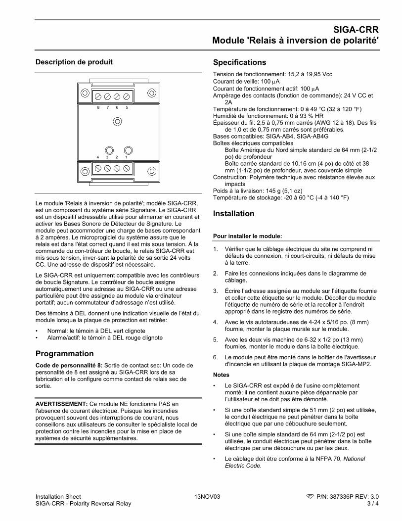
Installation Sheet 13NOV03 P/N: 387336P REV: 3.0 SIGA-CRR - Polarity Reversal Relay 3 / 4
SIGA-CRR Module 'Relais à inversion de polarité'
Description de produit
1234
5678
Le module 'Relais à inversion de polarité'; modèle SIGA-CRR, est un composant du système série Signature. Le SIGA-CRR est un dispositif adressable utilisé pour alimenter en courant et activer les Bases Sonore de Détecteur de Signature. Le module peut accommoder une charge de bases correspondant à 2 ampères. Le microprogiciel du système assure que le relais est dans l'état correct quand il est mis sous tension. À la commande du con-trôleur de boucle, le relais SIGA-CRR est mis sous tension, inver-sant la polarité de sa sortie 24 volts CC. Une adresse de dispositif est nécessaire.
Le SIGA-CRR est uniquement compatible avec les contrôleurs de boucle Signature. Le contrôleur de boucle assigne automatiquement une adresse au SIGA-CRR ou une adresse particulière peut être assignée au module via ordinateur portatif; aucun commutateur d’adressage n’est utilisé.
Des témoins à DEL donnent une indication visuelle de l’état du module lorsque la plaque de protection est retirée:
• Normal: le témoin à DEL vert clignote • Alarme/actif: le témoin à DEL rouge clignote
Programmation Code de personnalité 8: Sortie de contact sec: Un code de personalité de 8 est assigné au SIGA-CRR lors de sa fabrication et le configure comme contact de relais sec de sortie.
AVERTISSEMENT: Ce module NE fonctionne PAS en l'absence de courant électrique. Puisque les incendies provoquent souvent des interruptions de courant, nous conseillons aux utilisateurs de consulter le spécialiste local de protection contre les incendies pour la mise en place de systèmes de sécurité supplémentaires.
Specifications Tension de fonctionnement: 15,2 à 19,95 Vcc Courant de veille: 100 µA Courant de fonctionnement actif: 100 µA Ampèrage des contacts (fonction de commande): 24 V CC et
2A Température de fonctionnement: 0 à 49 °C (32 à 120 °F) Humidité de fonctionnement: 0 à 93 % HR Épaisseur du fil: 2,5 à 0,75 mm carrés (AWG 12 à 18). Des fils
de 1,0 et de 0,75 mm carrés sont préférables. Bases compatibles: SIGA-AB4, SIGA-AB4G Boîtes électriques compatibles Boîte Amérique du Nord simple standard de 64 mm (2-1/2
po) de profondeur Boîte carrée standard de 10,16 cm (4 po) de côté et 38
mm (1-1/2 po) de profondeur, avec couvercle simple Construction: Polymère technique avec résistance élevée aux
impacts Poids à la livraison: 145 g (5,1 oz) Température de stockage: -20 à 60 °C (-4 à 140 °F)
Installation
Pour installer le module:
1. Vérifier que le câblage électrique du site ne comprend ni défauts de connexion, ni court-circuits, ni défauts de mise à la terre.
2. Faire les connexions indiquées dans le diagramme de câblage.
3. Écrire l’adresse assignée au module sur l’étiquette fournie et coller cette étiquette sur le module. Décoller du module l’étiquette de numéro de série et la recoller à l’endroit approprié dans le registre des numéros de série.
4. Avec le vis autotaraudeuses de 4-24 x 5/16 po. (8 mm) fournie, monter la plaque murale sur le module.
5. Avec les deux vis machine de 6-32 x 1/2 po (13 mm) fournies, monter le module dans la boîte électrique.
6. Le module peut être monté dans le boîtier de l'avertisseur d'incendie en utilisant la plaque de montage SIGA-MP2.
Notes
• Le SIGA-CRR est expédié de l’usine complètement monté; il ne contient aucune pièce dépannable par l’utilisateur et ne doit pas être démonté.
• Si une boîte standard simple de 51 mm (2 po) est utilisée, le conduit électrique ne peut pénétrer dans la boîte électrique que par une débouchure seulement.
• Si une boîte simple standard de 64 mm (2-1/2 po) est utilisée, le conduit électrique peut pénétrer dans la boîte électrique par une débouchure ou par les deux.
• Le câblage doit être conforme à la NFPA 70, National Electric Code.
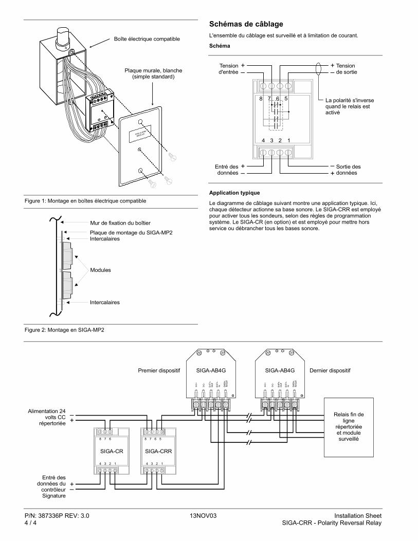
P/N: 387336P REV: 3.0 13NOV03 Installation Sheet 4 / 4 SIGA-CRR - Polarity Reversal Relay
Plaque murale, blanche (simple standard)
Boîte électrique compatible
Figure 1: Montage en boîtes électrique compatible
Plaque de montage du SIGA-MP2
Mur de fixation du boîtier
Intercalaires
Modules
Intercalaires
Figure 2: Montage en SIGA-MP2
Schémas de câblage L'ensemble du câblage est surveillé et à limitation de courant.
Schéma
8 7 6 5
4 3 2 1
+–
+–
+–
+–
Tensiond'entrée
Tensionde sortie
La polarité s'inverse quand le relais est activé
Entré desdonnées
Sortie desdonnées
Application typique
Le diagramme de câblage suivant montre une application typique. Ici, chaque détecteur actionne sa base sonore. Le SIGA-CRR est employé pour activer tous les sondeurs, selon des règles de programmation système. Le SIGA-CR (en option) et est employé pour mettre hors service ou débrancher tous les bases sonore.
Entré des données du
contrôleur Signature
Alimentation 24 volts CC
répertoriée
SIG
+
SIG
-
DAT
A+IN
/OU
T
SIGA-AB4G
–+
+–
Relais fin de ligne
répertoriée et module surveillé
SIG
+
SIG
-
DAT
A+IN
/OU
T
SIGA-AB4GPremier dispositif Dernier dispositif
8 7 6
4 3 2 1
SIGA-CR
8 7 6 5
4 3 2 1
SIGA-CRR
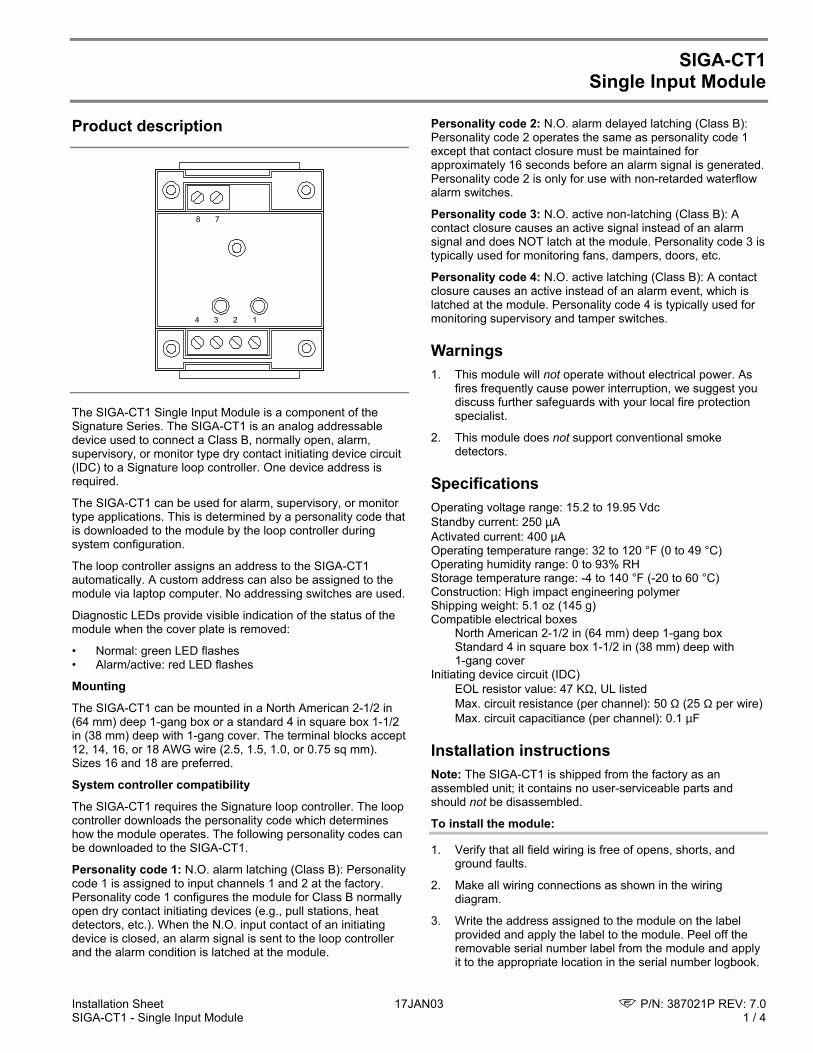
Installation Sheet 17JAN03 P/N: 387021P REV: 7.0SIGA-CT1 - Single Input Module 1 / 4
SIGA-CT1Single Input Module
Product description
1234
78
The SIGA-CT1 Single Input Module is a component of theSignature Series. The SIGA-CT1 is an analog addressabledevice used to connect a Class B, normally open, alarm,supervisory, or monitor type dry contact initiating device circuit(IDC) to a Signature loop controller. One device address isrequired.
The SIGA-CT1 can be used for alarm, supervisory, or monitortype applications. This is determined by a personality code thatis downloaded to the module by the loop controller duringsystem configuration.
The loop controller assigns an address to the SIGA-CT1automatically. A custom address can also be assigned to themodule via laptop computer. No addressing switches are used.
Diagnostic LEDs provide visible indication of the status of themodule when the cover plate is removed:
• Normal: green LED flashes• Alarm/active: red LED flashes
Mounting
The SIGA-CT1 can be mounted in a North American 2-1/2 in(64 mm) deep 1-gang box or a standard 4 in square box 1-1/2in (38 mm) deep with 1-gang cover. The terminal blocks accept12, 14, 16, or 18 AWG wire (2.5, 1.5, 1.0, or 0.75 sq mm).Sizes 16 and 18 are preferred.
System controller compatibility
The SIGA-CT1 requires the Signature loop controller. The loopcontroller downloads the personality code which determineshow the module operates. The following personality codes canbe downloaded to the SIGA-CT1.
Personality code 1: N.O. alarm latching (Class B): Personalitycode 1 is assigned to input channels 1 and 2 at the factory.Personality code 1 configures the module for Class B normallyopen dry contact initiating devices (e.g., pull stations, heatdetectors, etc.). When the N.O. input contact of an initiatingdevice is closed, an alarm signal is sent to the loop controllerand the alarm condition is latched at the module.
Personality code 2: N.O. alarm delayed latching (Class B):Personality code 2 operates the same as personality code 1except that contact closure must be maintained forapproximately 16 seconds before an alarm signal is generated.Personality code 2 is only for use with non-retarded waterflowalarm switches.
Personality code 3: N.O. active non-latching (Class B): Acontact closure causes an active signal instead of an alarmsignal and does NOT latch at the module. Personality code 3 istypically used for monitoring fans, dampers, doors, etc.
Personality code 4: N.O. active latching (Class B): A contactclosure causes an active instead of an alarm event, which islatched at the module. Personality code 4 is typically used formonitoring supervisory and tamper switches.
Warnings1. This module will not operate without electrical power. As
fires frequently cause power interruption, we suggest youdiscuss further safeguards with your local fire protectionspecialist.
2. This module does not support conventional smokedetectors.
SpecificationsOperating voltage range: 15.2 to 19.95 VdcStandby current: 250 µAActivated current: 400 µAOperating temperature range: 32 to 120 °F (0 to 49 °C)Operating humidity range: 0 to 93% RHStorage temperature range: -4 to 140 °F (-20 to 60 °C)Construction: High impact engineering polymerShipping weight: 5.1 oz (145 g)Compatible electrical boxes
North American 2-1/2 in (64 mm) deep 1-gang boxStandard 4 in square box 1-1/2 in (38 mm) deep with1-gang cover
Initiating device circuit (IDC)EOL resistor value: 47 KΩ, UL listedMax. circuit resistance (per channel): 50 Ω (25 Ω per wire)Max. circuit capacitiance (per channel): 0.1 µF
Installation instructionsNote: The SIGA-CT1 is shipped from the factory as anassembled unit; it contains no user-serviceable parts andshould not be disassembled.
To install the module:
1. Verify that all field wiring is free of opens, shorts, andground faults.
2. Make all wiring connections as shown in the wiringdiagram.
3. Write the address assigned to the module on the labelprovided and apply the label to the module. Peel off theremovable serial number label from the module and applyit to the appropriate location in the serial number logbook.
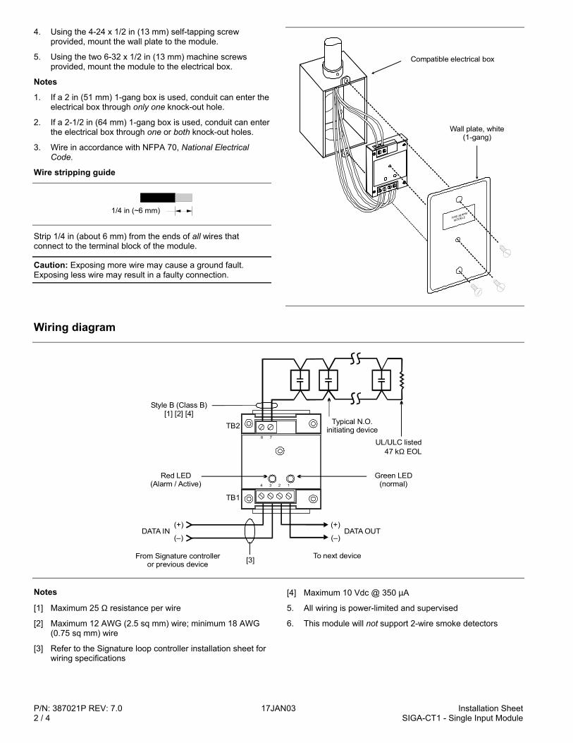
P/N: 387021P REV: 7.0 17JAN03 Installation Sheet2 / 4 SIGA-CT1 - Single Input Module
4. Using the 4-24 x 1/2 in (13 mm) self-tapping screwprovided, mount the wall plate to the module.
5. Using the two 6-32 x 1/2 in (13 mm) machine screwsprovided, mount the module to the electrical box.
Notes
1. If a 2 in (51 mm) 1-gang box is used, conduit can enter theelectrical box through only one knock-out hole.
2. If a 2-1/2 in (64 mm) 1-gang box is used, conduit can enterthe electrical box through one or both knock-out holes.
3. Wire in accordance with NFPA 70, National ElectricalCode.
Wire stripping guide
1/4 in (~6 mm)
Strip 1/4 in (about 6 mm) from the ends of all wires thatconnect to the terminal block of the module.
Caution: Exposing more wire may cause a ground fault.Exposing less wire may result in a faulty connection.
Compatible electrical box
Wall plate, white (1-gang)
Wiring diagram
(+)
(–)DATA OUT
Style B (Class B)[1] [2] [4]
Red LED(Alarm / Active)
TB2
TB1
Typical N.O.initiating device
UL/ULC listed47 k EOLΩ
Green LED(normal)
(+)
(–)
From Signature controlleror previous device [3] To next device
DATA IN
1234
78
Notes
[1] Maximum 25 Ω resistance per wire
[2] Maximum 12 AWG (2.5 sq mm) wire; minimum 18 AWG(0.75 sq mm) wire
[3] Refer to the Signature loop controller installation sheet forwiring specifications
[4] Maximum 10 Vdc @ 350 µA
5. All wiring is power-limited and supervised
6. This module will not support 2-wire smoke detectors
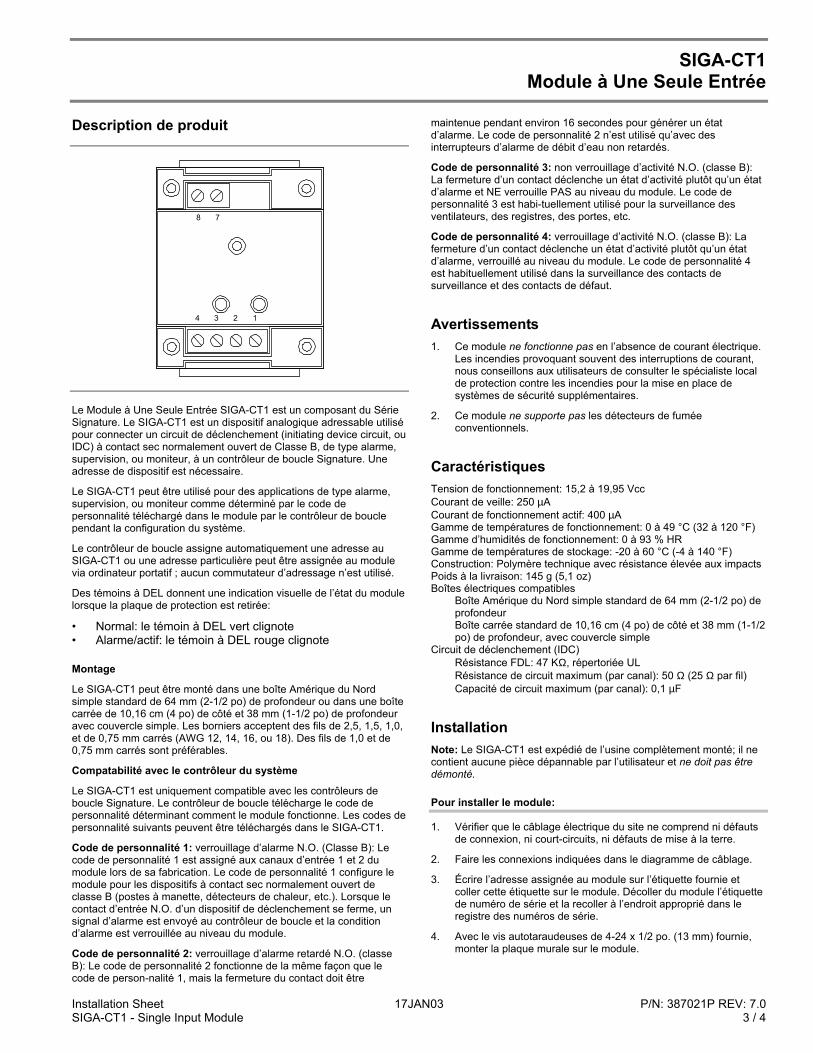
Installation Sheet 17JAN03 P/N: 387021P REV: 7.0SIGA-CT1 - Single Input Module 3 / 4
SIGA-CT1Module à Une Seule Entrée
Description de produit
1234
78
Le Module à Une Seule Entrée SIGA-CT1 est un composant du SérieSignature. Le SIGA-CT1 est un dispositif analogique adressable utilisépour connecter un circuit de déclenchement (initiating device circuit, ouIDC) à contact sec normalement ouvert de Classe B, de type alarme,supervision, ou moniteur, à un contrôleur de boucle Signature. Uneadresse de dispositif est nécessaire.
Le SIGA-CT1 peut être utilisé pour des applications de type alarme,supervision, ou moniteur comme déterminé par le code depersonnalité téléchargé dans le module par le contrôleur de bouclependant la configuration du système.
Le contrôleur de boucle assigne automatiquement une adresse auSIGA-CT1 ou une adresse particulière peut être assignée au modulevia ordinateur portatif ; aucun commutateur d’adressage n’est utilisé.
Des témoins à DEL donnent une indication visuelle de l’état du modulelorsque la plaque de protection est retirée:
• Normal: le témoin à DEL vert clignote• Alarme/actif: le témoin à DEL rouge clignote
Montage
Le SIGA-CT1 peut être monté dans une boîte Amérique du Nordsimple standard de 64 mm (2-1/2 po) de profondeur ou dans une boîtecarrée de 10,16 cm (4 po) de côté et 38 mm (1-1/2 po) de profondeuravec couvercle simple. Les borniers acceptent des fils de 2,5, 1,5, 1,0,et de 0,75 mm carrés (AWG 12, 14, 16, ou 18). Des fils de 1,0 et de0,75 mm carrés sont préférables.
Compatabilité avec le contrôleur du système
Le SIGA-CT1 est uniquement compatible avec les contrôleurs deboucle Signature. Le contrôleur de boucle télécharge le code depersonnalité déterminant comment le module fonctionne. Les codes depersonnalité suivants peuvent être téléchargés dans le SIGA-CT1.
Code de personnalité 1: verrouillage d’alarme N.O. (Classe B): Lecode de personnalité 1 est assigné aux canaux d’entrée 1 et 2 dumodule lors de sa fabrication. Le code de personnalité 1 configure lemodule pour les dispositifs à contact sec normalement ouvert declasse B (postes à manette, détecteurs de chaleur, etc.). Lorsque lecontact d’entrée N.O. d’un dispositif de déclenchement se ferme, unsignal d’alarme est envoyé au contrôleur de boucle et la conditiond’alarme est verrouillée au niveau du module.
Code de personnalité 2: verrouillage d’alarme retardé N.O. (classeB): Le code de personnalité 2 fonctionne de la même façon que lecode de person-nalité 1, mais la fermeture du contact doit être
maintenue pendant environ 16 secondes pour générer un étatd’alarme. Le code de personnalité 2 n’est utilisé qu’avec desinterrupteurs d’alarme de débit d’eau non retardés.
Code de personnalité 3: non verrouillage d’activité N.O. (classe B):La fermeture d’un contact déclenche un état d’activité plutôt qu’un étatd’alarme et NE verrouille PAS au niveau du module. Le code depersonnalité 3 est habi-tuellement utilisé pour la surveillance desventilateurs, des registres, des portes, etc.
Code de personnalité 4: verrouillage d’activité N.O. (classe B): Lafermeture d’un contact déclenche un état d’activité plutôt qu’un étatd’alarme, verrouillé au niveau du module. Le code de personnalité 4est habituellement utilisé dans la surveillance des contacts desurveillance et des contacts de défaut.
Avertissements1. Ce module ne fonctionne pas en l’absence de courant électrique.
Les incendies provoquant souvent des interruptions de courant,nous conseillons aux utilisateurs de consulter le spécialiste localde protection contre les incendies pour la mise en place desystèmes de sécurité supplémentaires.
2. Ce module ne supporte pas les détecteurs de fuméeconventionnels.
CaractéristiquesTension de fonctionnement: 15,2 à 19,95 VccCourant de veille: 250 µACourant de fonctionnement actif: 400 µAGamme de températures de fonctionnement: 0 à 49 °C (32 à 120 °F)Gamme d’humidités de fonctionnement: 0 à 93 % HRGamme de températures de stockage: -20 à 60 °C (-4 à 140 °F)Construction: Polymère technique avec résistance élevée aux impactsPoids à la livraison: 145 g (5,1 oz)Boîtes électriques compatibles
Boîte Amérique du Nord simple standard de 64 mm (2-1/2 po) deprofondeurBoîte carrée standard de 10,16 cm (4 po) de côté et 38 mm (1-1/2po) de profondeur, avec couvercle simple
Circuit de déclenchement (IDC)Résistance FDL: 47 KΩ, répertoriée ULRésistance de circuit maximum (par canal): 50 Ω (25 Ω par fil)Capacité de circuit maximum (par canal): 0,1 µF
InstallationNote: Le SIGA-CT1 est expédié de l’usine complètement monté; il necontient aucune pièce dépannable par l’utilisateur et ne doit pas êtredémonté.
Pour installer le module:
1. Vérifier que le câblage électrique du site ne comprend ni défautsde connexion, ni court-circuits, ni défauts de mise à la terre.
2. Faire les connexions indiquées dans le diagramme de câblage.
3. Écrire l’adresse assignée au module sur l’étiquette fournie etcoller cette étiquette sur le module. Décoller du module l’étiquettede numéro de série et la recoller à l’endroit approprié dans leregistre des numéros de série.
4. Avec le vis autotaraudeuses de 4-24 x 1/2 po. (13 mm) fournie,monter la plaque murale sur le module.
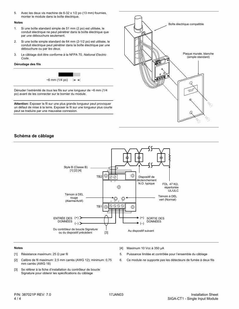
P/N: 387021P REV: 7.0 17JAN03 Installation Sheet4 / 4 SIGA-CT1 - Single Input Module
5. Avec les deux vis machine de 6-32 x 1/2 po (13 mm) fournies,monter le module dans la boîte électrique.
Notes
1. Si une boîte standard simple de 51 mm (2 po) est utilisée, leconduit électrique ne peut pénétrer dans la boîte électrique quepar une débouchure seulement.
2. Si une boîte simple standard de 64 mm (2-1/2 po) est utilisée, leconduit électrique peut pénétrer dans la boîte électrique par unedébouchure ou par les deux.
3. Le câblage doit être conforme à la NFPA 70, National ElectricCode.
Dénudage des fils
~6 mm 1/4 po ( )
Dénuder l’extrémité de tous les fils sur une longueur de ~6 mm (1/4po) avant de les connecter sur le bornier du module.
Attention: Exposer le fil sur une plus grande longueur peut provoquerun défaut de mise à la terre. Exposer le fil sur une longueur plus courtepeut se traduire par une mauvaise connexion.
Boîte électrique compatible
Plaque murale, blanche (simple standard)
Schéma de câblage
(+)
(–)
TB2
TB1
(+)
(–)
[3]
1234
78
Au dispositif suivantDu contrôleur de boucle Signature ou du dispositif précédent
Témoin à DEL vert (Normal)
FDL 47 K , répertoriée
UL/ULC
Ω
ENTRÉE DES DONNÉES
Témoin à DEL rouge
(Alarme/Actif)
SORTIE DES DONNÉES
Style B (Classe B)[1] [2] [4]
Dispositif dedéclenchement
N.O. typique
Notes
[1] Résistance maximum: 25 Ω par fil
[2] Calibre de fil maximum: 2,5 mm carrés (AWG 12); minimum: 0,75mm carrés (AWG 18)
[3] Se référer à la fiche d’installation du contrôleur de boucleSignature pour obtenir les spécifications du câblage
[4] Maximum 10 Vcc à 350 µA
5. Puissance limitée et contrôlée pour l’ensemble du câblage
6. Ce module ne supporte pas les détecteurs de fumée à deux fils
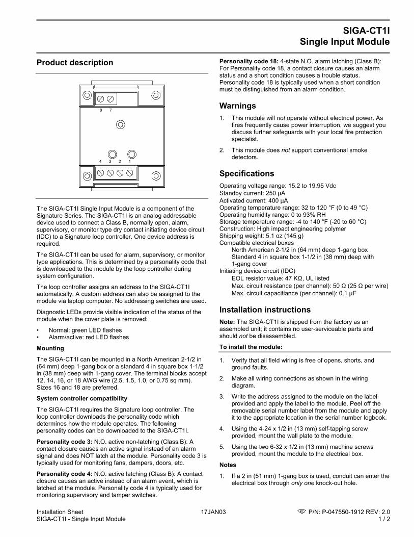
Installation Sheet 17JAN03 P/N: P-047550-1912 REV: 2.0SIGA-CT1I - Single Input Module 1 / 2
SIGA-CT1ISingle Input Module
Product description
1234
78
The SIGA-CT1I Single Input Module is a component of theSignature Series. The SIGA-CT1I is an analog addressabledevice used to connect a Class B, normally open, alarm,supervisory, or monitor type dry contact initiating device circuit(IDC) to a Signature loop controller. One device address isrequired.
The SIGA-CT1I can be used for alarm, supervisory, or monitortype applications. This is determined by a personality code thatis downloaded to the module by the loop controller duringsystem configuration.
The loop controller assigns an address to the SIGA-CT1Iautomatically. A custom address can also be assigned to themodule via laptop computer. No addressing switches are used.
Diagnostic LEDs provide visible indication of the status of themodule when the cover plate is removed:
• Normal: green LED flashes• Alarm/active: red LED flashes
Mounting
The SIGA-CT1I can be mounted in a North American 2-1/2 in(64 mm) deep 1-gang box or a standard 4 in square box 1-1/2in (38 mm) deep with 1-gang cover. The terminal blocks accept12, 14, 16, or 18 AWG wire (2.5, 1.5, 1.0, or 0.75 sq mm).Sizes 16 and 18 are preferred.
System controller compatibility
The SIGA-CT1I requires the Signature loop controller. Theloop controller downloads the personality code whichdetermines how the module operates. The followingpersonality codes can be downloaded to the SIGA-CT1I.
Personality code 3: N.O. active non-latching (Class B): Acontact closure causes an active signal instead of an alarmsignal and does NOT latch at the module. Personality code 3 istypically used for monitoring fans, dampers, doors, etc.
Personality code 4: N.O. active latching (Class B): A contactclosure causes an active instead of an alarm event, which islatched at the module. Personality code 4 is typically used formonitoring supervisory and tamper switches.
Personality code 18: 4-state N.O. alarm latching (Class B):For Personality code 18, a contact closure causes an alarmstatus and a short condition causes a trouble status.Personality code 18 is typically used when a short conditionmust be distinguished from an alarm condition.
Warnings1. This module will not operate without electrical power. As
fires frequently cause power interruption, we suggest youdiscuss further safeguards with your local fire protectionspecialist.
2. This module does not support conventional smokedetectors.
SpecificationsOperating voltage range: 15.2 to 19.95 VdcStandby current: 250 µAActivated current: 400 µAOperating temperature range: 32 to 120 °F (0 to 49 °C)Operating humidity range: 0 to 93% RHStorage temperature range: -4 to 140 °F (-20 to 60 °C)Construction: High impact engineering polymerShipping weight: 5.1 oz (145 g)Compatible electrical boxes
North American 2-1/2 in (64 mm) deep 1-gang boxStandard 4 in square box 1-1/2 in (38 mm) deep with1-gang cover
Initiating device circuit (IDC)EOL resistor value: 47 KΩ, UL listedMax. circuit resistance (per channel): 50 Ω (25 Ω per wire)Max. circuit capacitiance (per channel): 0.1 µF
Installation instructionsNote: The SIGA-CT1I is shipped from the factory as anassembled unit; it contains no user-serviceable parts andshould not be disassembled.
To install the module:
1. Verify that all field wiring is free of opens, shorts, andground faults.
2. Make all wiring connections as shown in the wiringdiagram.
3. Write the address assigned to the module on the labelprovided and apply the label to the module. Peel off theremovable serial number label from the module and applyit to the appropriate location in the serial number logbook.
4. Using the 4-24 x 1/2 in (13 mm) self-tapping screwprovided, mount the wall plate to the module.
5. Using the two 6-32 x 1/2 in (13 mm) machine screwsprovided, mount the module to the electrical box.
Notes
1. If a 2 in (51 mm) 1-gang box is used, conduit can enter theelectrical box through only one knock-out hole.
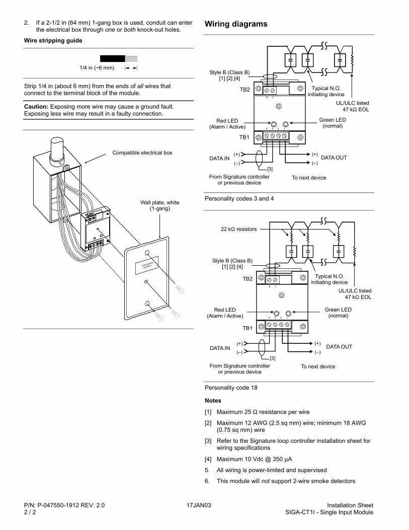
P/N: P-047550-1912 REV: 2.0 17JAN03 Installation Sheet2 / 2 SIGA-CT1I - Single Input Module
2. If a 2-1/2 in (64 mm) 1-gang box is used, conduit can enterthe electrical box through one or both knock-out holes.
Wire stripping guide
1/4 in (~6 mm)
Strip 1/4 in (about 6 mm) from the ends of all wires thatconnect to the terminal block of the module.
Caution: Exposing more wire may cause a ground fault.Exposing less wire may result in a faulty connection.
Compatible electrical box
Wall plate, white (1-gang)
Wiring diagrams
(+)
(–)DATA OUT
Style B (Class B)[1] [2] [4]
Red LED(Alarm / Active)
TB2
TB1
Typical N.O.initiating device
UL/ULC listed47 k EOLΩ
Green LED(normal)
(+)
(–)
From Signature controlleror previous device
[3]
To next device
DATA IN
1234
78
Personality codes 3 and 4
(+)
(–)DATA OUT
Style B (Class B)[1] [2] [4]
Red LED(Alarm / Active)
TB2
TB1
Typical N.O.initiating device
UL/ULC listed47 k EOLΩ
Green LED(normal)
(+)
(–)
From Signature controlleror previous device
[3]
To next device
DATA IN
1234
78
22 k resistorsΩ
Personality code 18
Notes
[1] Maximum 25 Ω resistance per wire
[2] Maximum 12 AWG (2.5 sq mm) wire; minimum 18 AWG(0.75 sq mm) wire
[3] Refer to the Signature loop controller installation sheet forwiring specifications
[4] Maximum 10 Vdc @ 350 µA
5. All wiring is power-limited and supervised
6. This module will not support 2-wire smoke detectors

Installation Sheet 17JAN03 P/N: 387037P REV: 8.0SIGA-CT2 - Dual Input Module 1 / 4
SIGA-CT2Dual Input Module
Product description
1234
5678
The SIGA-CT2 Dual Input Module is a component of theSignature Series. The SIGA-CT2 is an analog addressabledevice used to connect one or two Class B, normally open,alarm, supervisory, or monitor type dry contact initiating devicecircuits (IDCs) to a Signature loop controller. Two deviceaddresses are required.
The SIGA-CT2 can be used for alarm, supervisory, or monitortype applications. This is determined by a personality code thatis downloaded to the module by the loop controller duringsystem configuration.
The loop controller assigns an address to the SIGA-CT2automatically. A custom address can also be assigned to themodule via laptop computer. No addressing switches are used.
Diagnostic LEDs provide visible indication of the status of themodule when the cover plate is removed:
• Normal: green LED flashes• Alarm/active: red LED flashes
Mounting
The SIGA-CT2 can be mounted in a North American 2-1/2 in(64 mm) deep 1-gang box or a standard 4 in square box 1-1/2in (38 mm) deep with 1-gang cover. The terminal blocks accept12, 14, 16, or 18 AWG wire (2.5, 1.5, 1.0, or 0.75 sq mm).Sizes 16 and 18 are preferred.
System controller compatibility
The SIGA-CT2 requires the Signature loop controller. The loopcontroller downloads the personality code which determineshow the module operates. The following personality codes canbe downloaded to the SIGA-CT2.
Personality code 1: N.O. alarm latching (Class B): Personalitycode 1 is assigned to input channels 1 and 2 at the factory.Personality code 1 configures the module for Class B normallyopen dry contact initiating devices (e.g., pull stations, heatdetectors, etc.). When the N.O. input contact of an initiatingdevice is closed, an alarm signal is sent to the loop controllerand the alarm condition is latched at the module.
Personality code 2: N.O. alarm delayed latching (Class B):Personality code 2 operates the same as personality code 1except that contact closure must be maintained forapproximately 16 seconds before an alarm signal is generated.Personality code 2 is only for use with non-retarded waterflowalarm switches.
Personality code 3: N.O. active non-latching (Class B): Acontact closure causes an active signal instead of an alarmsignal and does NOT latch at the module. Personality code 3 istypically used for monitoring fans, dampers, doors, etc.
Personality code 4: N.O. active latching (Class B): A contactclosure causes an active instead of an alarm event, which islatched at the module. Personality code 4 is typically used formonitoring supervisory and tamper switches.
Warnings1. This module will not operate without electrical power. As
fires frequently cause power interruption, we suggest youdiscuss further safeguards with your local fire protectionspecialist.
2. This module does not support conventional smokedetectors.
SpecificationsOperating voltage range: 15.2 to 19.95 VdcStandby current: 396 µAActivated current: 680 µAOperating temperature range: 32 to 120 °F (0 to 49 °C)Operating humidity range: 0 to 93% RHStorage temperature range: -4 to 140 °F (-20 to 60 °C)Construction: High impact engineering polymerShipping weight: 5.1 oz (145 g)Compatible electrical boxes
North American 2-1/2 in (64 mm) deep 1-gang boxStandard 4 in square box 1-1/2 in (38 mm) deep with1-gang cover
Initiating device circuit (IDC)EOL resistor value: 47 KΩ, UL listedMax. circuit resistance (per channel): 50 Ω (25 Ω per wire)Max. circuit capacitiance (per channel): 0.1 µF
Installation instructionsNote: The SIGA-CT2 is shipped from the factory as anassembled unit; it contains no user-serviceable parts andshould not be disassembled.
To install the module:
1. Verify that all field wiring is free of opens, shorts, andground faults.
2. Make all wiring connections as shown in the wiringdiagram.
3. Write the address assigned to the module on the labelprovided and apply the label to the module. Peel off theremovable serial number label from the module and applyit to the appropriate location in the serial number logbook.
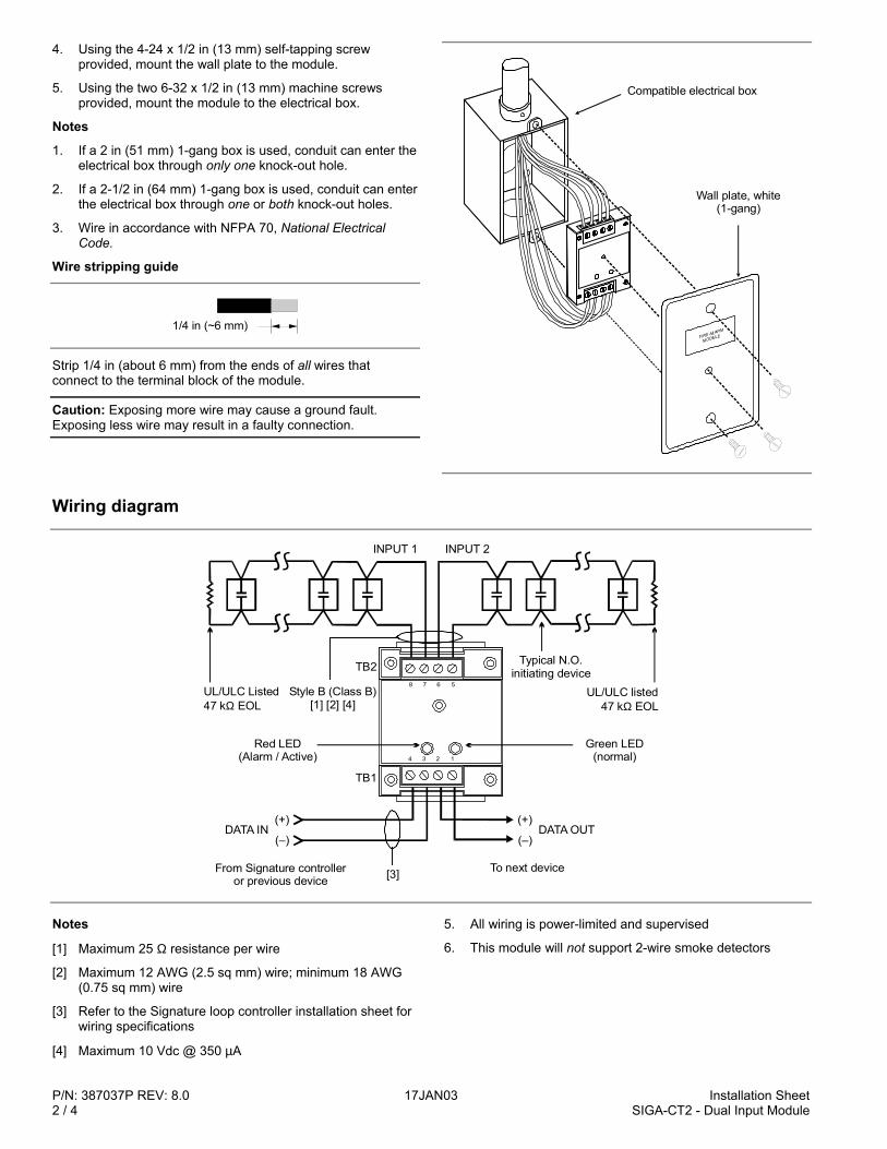
P/N: 387037P REV: 8.0 17JAN03 Installation Sheet2 / 4 SIGA-CT2 - Dual Input Module
4. Using the 4-24 x 1/2 in (13 mm) self-tapping screwprovided, mount the wall plate to the module.
5. Using the two 6-32 x 1/2 in (13 mm) machine screwsprovided, mount the module to the electrical box.
Notes
1. If a 2 in (51 mm) 1-gang box is used, conduit can enter theelectrical box through only one knock-out hole.
2. If a 2-1/2 in (64 mm) 1-gang box is used, conduit can enterthe electrical box through one or both knock-out holes.
3. Wire in accordance with NFPA 70, National ElectricalCode.
Wire stripping guide
1/4 in (~6 mm)
Strip 1/4 in (about 6 mm) from the ends of all wires thatconnect to the terminal block of the module.
Caution: Exposing more wire may cause a ground fault.Exposing less wire may result in a faulty connection.
Compatible electrical box
Wall plate, white(1-gang)
Wiring diagram
(+)
(–)DATA OUT
INPUT 1 INPUT 2
UL/ULC Listed47 k EOLΩ
Style B (Class B)[1] [2] [4]
Red LED(Alarm / Active)
TB2
TB1
Typical N.O.initiating device
UL/ULC listed47 k EOLΩ
Green LED(normal)
(+)
(–)
From Signature controlleror previous device [3] To next device
DATA IN
1234
5678
Notes
[1] Maximum 25 Ω resistance per wire
[2] Maximum 12 AWG (2.5 sq mm) wire; minimum 18 AWG(0.75 sq mm) wire
[3] Refer to the Signature loop controller installation sheet forwiring specifications
[4] Maximum 10 Vdc @ 350 µA
5. All wiring is power-limited and supervised
6. This module will not support 2-wire smoke detectors
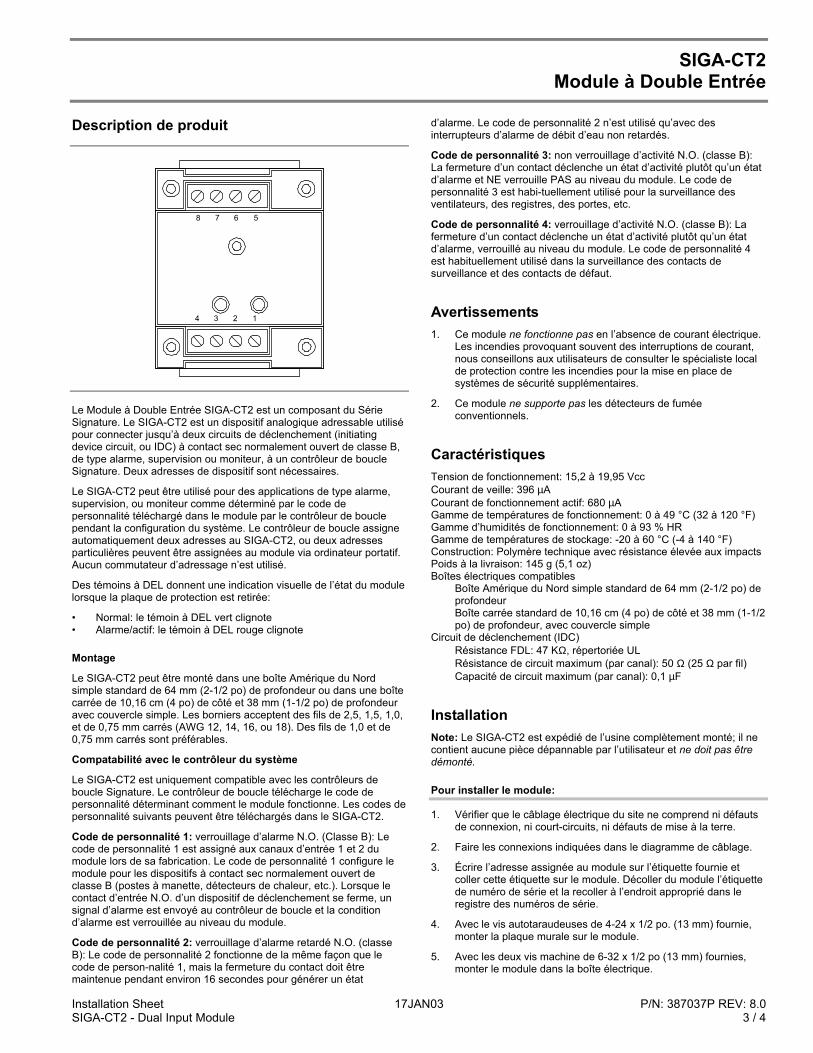
Installation Sheet 17JAN03 P/N: 387037P REV: 8.0SIGA-CT2 - Dual Input Module 3 / 4
SIGA-CT2Module à Double Entrée
Description de produit
1234
5678
Le Module à Double Entrée SIGA-CT2 est un composant du SérieSignature. Le SIGA-CT2 est un dispositif analogique adressable utilisépour connecter jusqu’à deux circuits de déclenchement (initiatingdevice circuit, ou IDC) à contact sec normalement ouvert de classe B,de type alarme, supervision ou moniteur, à un contrôleur de boucleSignature. Deux adresses de dispositif sont nécessaires.
Le SIGA-CT2 peut être utilisé pour des applications de type alarme,supervision, ou moniteur comme déterminé par le code depersonnalité téléchargé dans le module par le contrôleur de bouclependant la configuration du système. Le contrôleur de boucle assigneautomatiquement deux adresses au SIGA-CT2, ou deux adressesparticulières peuvent être assignées au module via ordinateur portatif.Aucun commutateur d’adressage n’est utilisé.
Des témoins à DEL donnent une indication visuelle de l’état du modulelorsque la plaque de protection est retirée:
• Normal: le témoin à DEL vert clignote• Alarme/actif: le témoin à DEL rouge clignote
Montage
Le SIGA-CT2 peut être monté dans une boîte Amérique du Nordsimple standard de 64 mm (2-1/2 po) de profondeur ou dans une boîtecarrée de 10,16 cm (4 po) de côté et 38 mm (1-1/2 po) de profondeuravec couvercle simple. Les borniers acceptent des fils de 2,5, 1,5, 1,0,et de 0,75 mm carrés (AWG 12, 14, 16, ou 18). Des fils de 1,0 et de0,75 mm carrés sont préférables.
Compatabilité avec le contrôleur du système
Le SIGA-CT2 est uniquement compatible avec les contrôleurs deboucle Signature. Le contrôleur de boucle télécharge le code depersonnalité déterminant comment le module fonctionne. Les codes depersonnalité suivants peuvent être téléchargés dans le SIGA-CT2.
Code de personnalité 1: verrouillage d’alarme N.O. (Classe B): Lecode de personnalité 1 est assigné aux canaux d’entrée 1 et 2 dumodule lors de sa fabrication. Le code de personnalité 1 configure lemodule pour les dispositifs à contact sec normalement ouvert declasse B (postes à manette, détecteurs de chaleur, etc.). Lorsque lecontact d’entrée N.O. d’un dispositif de déclenchement se ferme, unsignal d’alarme est envoyé au contrôleur de boucle et la conditiond’alarme est verrouillée au niveau du module.
Code de personnalité 2: verrouillage d’alarme retardé N.O. (classeB): Le code de personnalité 2 fonctionne de la même façon que lecode de person-nalité 1, mais la fermeture du contact doit êtremaintenue pendant environ 16 secondes pour générer un état
d’alarme. Le code de personnalité 2 n’est utilisé qu’avec desinterrupteurs d’alarme de débit d’eau non retardés.
Code de personnalité 3: non verrouillage d’activité N.O. (classe B):La fermeture d’un contact déclenche un état d’activité plutôt qu’un étatd’alarme et NE verrouille PAS au niveau du module. Le code depersonnalité 3 est habi-tuellement utilisé pour la surveillance desventilateurs, des registres, des portes, etc.
Code de personnalité 4: verrouillage d’activité N.O. (classe B): Lafermeture d’un contact déclenche un état d’activité plutôt qu’un étatd’alarme, verrouillé au niveau du module. Le code de personnalité 4est habituellement utilisé dans la surveillance des contacts desurveillance et des contacts de défaut.
Avertissements1. Ce module ne fonctionne pas en l’absence de courant électrique.
Les incendies provoquant souvent des interruptions de courant,nous conseillons aux utilisateurs de consulter le spécialiste localde protection contre les incendies pour la mise en place desystèmes de sécurité supplémentaires.
2. Ce module ne supporte pas les détecteurs de fuméeconventionnels.
CaractéristiquesTension de fonctionnement: 15,2 à 19,95 VccCourant de veille: 396 µACourant de fonctionnement actif: 680 µAGamme de températures de fonctionnement: 0 à 49 °C (32 à 120 °F)Gamme d’humidités de fonctionnement: 0 à 93 % HRGamme de températures de stockage: -20 à 60 °C (-4 à 140 °F)Construction: Polymère technique avec résistance élevée aux impactsPoids à la livraison: 145 g (5,1 oz)Boîtes électriques compatibles
Boîte Amérique du Nord simple standard de 64 mm (2-1/2 po) deprofondeurBoîte carrée standard de 10,16 cm (4 po) de côté et 38 mm (1-1/2po) de profondeur, avec couvercle simple
Circuit de déclenchement (IDC)Résistance FDL: 47 KΩ, répertoriée ULRésistance de circuit maximum (par canal): 50 Ω (25 Ω par fil)Capacité de circuit maximum (par canal): 0,1 µF
InstallationNote: Le SIGA-CT2 est expédié de l’usine complètement monté; il necontient aucune pièce dépannable par l’utilisateur et ne doit pas êtredémonté.
Pour installer le module:
1. Vérifier que le câblage électrique du site ne comprend ni défautsde connexion, ni court-circuits, ni défauts de mise à la terre.
2. Faire les connexions indiquées dans le diagramme de câblage.
3. Écrire l’adresse assignée au module sur l’étiquette fournie etcoller cette étiquette sur le module. Décoller du module l’étiquettede numéro de série et la recoller à l’endroit approprié dans leregistre des numéros de série.
4. Avec le vis autotaraudeuses de 4-24 x 1/2 po. (13 mm) fournie,monter la plaque murale sur le module.
5. Avec les deux vis machine de 6-32 x 1/2 po (13 mm) fournies,monter le module dans la boîte électrique.
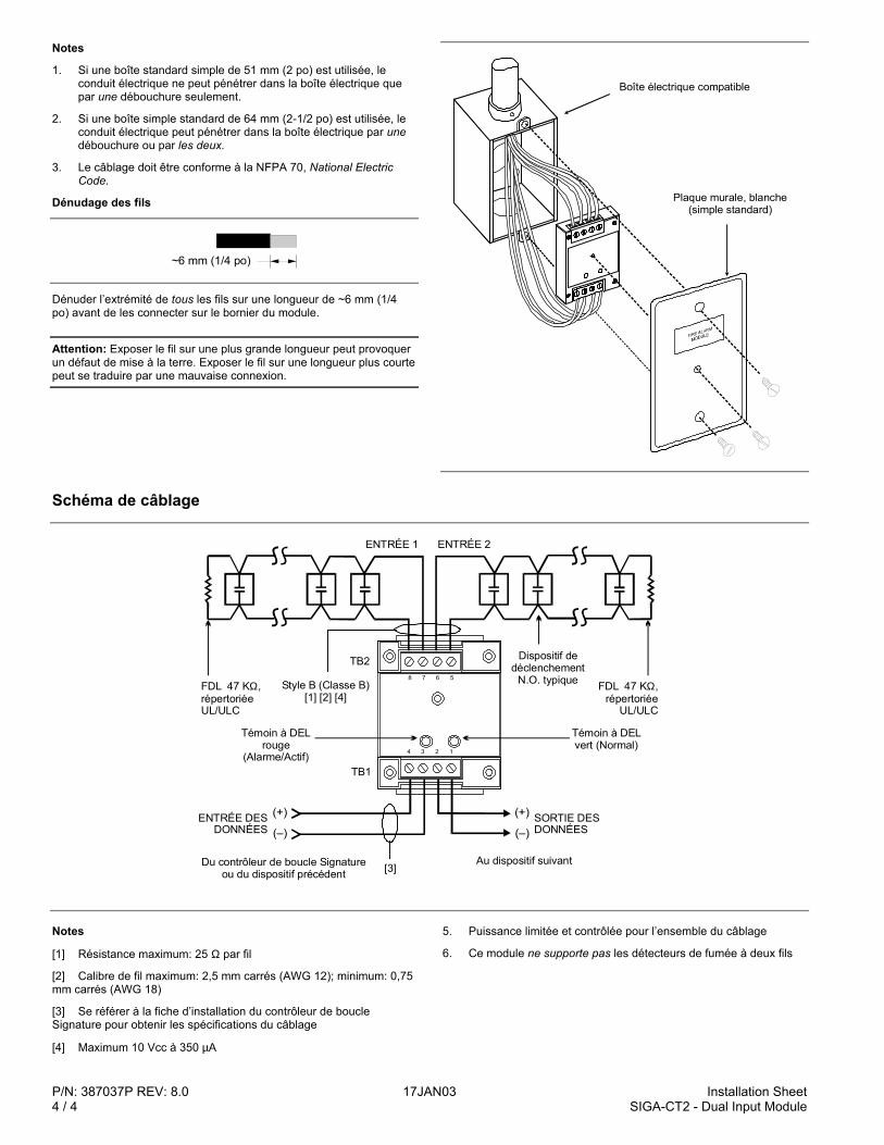
P/N: 387037P REV: 8.0 17JAN03 Installation Sheet4 / 4 SIGA-CT2 - Dual Input Module
Notes
1. Si une boîte standard simple de 51 mm (2 po) est utilisée, leconduit électrique ne peut pénétrer dans la boîte électrique quepar une débouchure seulement.
2. Si une boîte simple standard de 64 mm (2-1/2 po) est utilisée, leconduit électrique peut pénétrer dans la boîte électrique par unedébouchure ou par les deux.
3. Le câblage doit être conforme à la NFPA 70, National ElectricCode.
Dénudage des fils
~6 mm 1/4 po ( )
Dénuder l’extrémité de tous les fils sur une longueur de ~6 mm (1/4po) avant de les connecter sur le bornier du module.
Attention: Exposer le fil sur une plus grande longueur peut provoquerun défaut de mise à la terre. Exposer le fil sur une longueur plus courtepeut se traduire par une mauvaise connexion.
Plaque murale, blanche (simple standard)
Boîte électrique compatible
Schéma de câblage
1234
5678
Au dispositif suivantDu contrôleur de boucle Signature ou du dispositif précédent
Témoin à DEL vert (Normal)
FDL 47 K , répertoriée
UL/ULC
Ω
(+)
(–)
TB2
TB1
(+)
(–)
[3]
ENTRÉE DES DONNÉES
Témoin à DEL rouge
(Alarme/Actif)
SORTIE DES DONNÉES
ENTRÉE 1 ENTRÉE 2
FDL 47 K , répertoriée UL/ULC
Ω Style B (Classe B)[1] [2] [4]
Dispositif dedéclenchement
N.O. typique
Notes
[1] Résistance maximum: 25 Ω par fil
[2] Calibre de fil maximum: 2,5 mm carrés (AWG 12); minimum: 0,75mm carrés (AWG 18)
[3] Se référer à la fiche d’installation du contrôleur de boucleSignature pour obtenir les spécifications du câblage
[4] Maximum 10 Vcc à 350 µA
5. Puissance limitée et contrôlée pour l’ensemble du câblage
6. Ce module ne supporte pas les détecteurs de fumée à deux fils
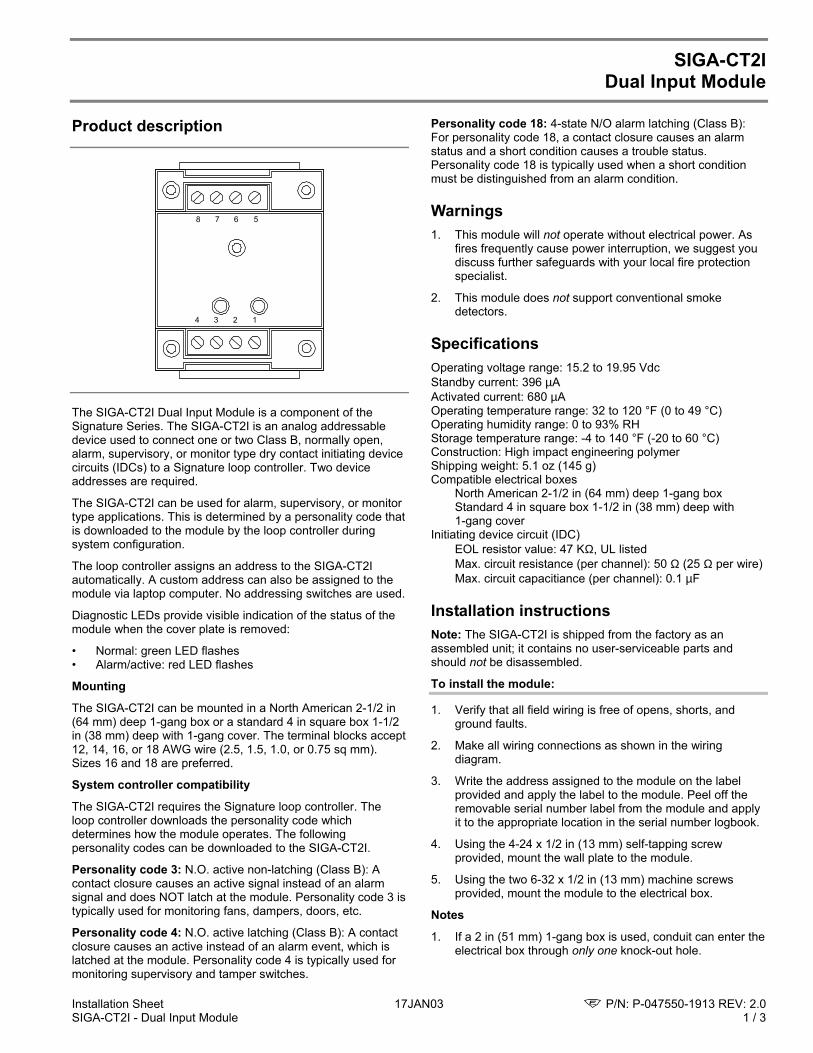
Installation Sheet 17JAN03 P/N: P-047550-1913 REV: 2.0SIGA-CT2I - Dual Input Module 1 / 3
SIGA-CT2IDual Input Module
Product description
1234
5678
The SIGA-CT2I Dual Input Module is a component of theSignature Series. The SIGA-CT2I is an analog addressabledevice used to connect one or two Class B, normally open,alarm, supervisory, or monitor type dry contact initiating devicecircuits (IDCs) to a Signature loop controller. Two deviceaddresses are required.
The SIGA-CT2I can be used for alarm, supervisory, or monitortype applications. This is determined by a personality code thatis downloaded to the module by the loop controller duringsystem configuration.
The loop controller assigns an address to the SIGA-CT2Iautomatically. A custom address can also be assigned to themodule via laptop computer. No addressing switches are used.
Diagnostic LEDs provide visible indication of the status of themodule when the cover plate is removed:
• Normal: green LED flashes• Alarm/active: red LED flashes
Mounting
The SIGA-CT2I can be mounted in a North American 2-1/2 in(64 mm) deep 1-gang box or a standard 4 in square box 1-1/2in (38 mm) deep with 1-gang cover. The terminal blocks accept12, 14, 16, or 18 AWG wire (2.5, 1.5, 1.0, or 0.75 sq mm).Sizes 16 and 18 are preferred.
System controller compatibility
The SIGA-CT2I requires the Signature loop controller. Theloop controller downloads the personality code whichdetermines how the module operates. The followingpersonality codes can be downloaded to the SIGA-CT2I.
Personality code 3: N.O. active non-latching (Class B): Acontact closure causes an active signal instead of an alarmsignal and does NOT latch at the module. Personality code 3 istypically used for monitoring fans, dampers, doors, etc.
Personality code 4: N.O. active latching (Class B): A contactclosure causes an active instead of an alarm event, which islatched at the module. Personality code 4 is typically used formonitoring supervisory and tamper switches.
Personality code 18: 4-state N/O alarm latching (Class B):For personality code 18, a contact closure causes an alarmstatus and a short condition causes a trouble status.Personality code 18 is typically used when a short conditionmust be distinguished from an alarm condition.
Warnings1. This module will not operate without electrical power. As
fires frequently cause power interruption, we suggest youdiscuss further safeguards with your local fire protectionspecialist.
2. This module does not support conventional smokedetectors.
SpecificationsOperating voltage range: 15.2 to 19.95 VdcStandby current: 396 µAActivated current: 680 µAOperating temperature range: 32 to 120 °F (0 to 49 °C)Operating humidity range: 0 to 93% RHStorage temperature range: -4 to 140 °F (-20 to 60 °C)Construction: High impact engineering polymerShipping weight: 5.1 oz (145 g)Compatible electrical boxes
North American 2-1/2 in (64 mm) deep 1-gang boxStandard 4 in square box 1-1/2 in (38 mm) deep with1-gang cover
Initiating device circuit (IDC)EOL resistor value: 47 KΩ, UL listedMax. circuit resistance (per channel): 50 Ω (25 Ω per wire)Max. circuit capacitiance (per channel): 0.1 µF
Installation instructionsNote: The SIGA-CT2I is shipped from the factory as anassembled unit; it contains no user-serviceable parts andshould not be disassembled.
To install the module:
1. Verify that all field wiring is free of opens, shorts, andground faults.
2. Make all wiring connections as shown in the wiringdiagram.
3. Write the address assigned to the module on the labelprovided and apply the label to the module. Peel off theremovable serial number label from the module and applyit to the appropriate location in the serial number logbook.
4. Using the 4-24 x 1/2 in (13 mm) self-tapping screwprovided, mount the wall plate to the module.
5. Using the two 6-32 x 1/2 in (13 mm) machine screwsprovided, mount the module to the electrical box.
Notes
1. If a 2 in (51 mm) 1-gang box is used, conduit can enter theelectrical box through only one knock-out hole.
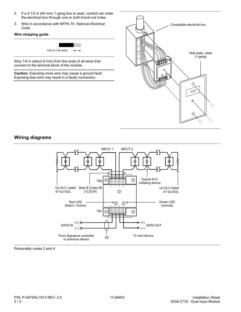
P/N: P-047550-1913 REV: 2.0 17JAN03 Installation Sheet2 / 3 SIGA-CT2I - Dual Input Module
2. If a 2-1/2 in (64 mm) 1-gang box is used, conduit can enterthe electrical box through one or both knock-out holes.
3. Wire in accordance with NFPA 70, National ElectricalCode.
Wire stripping guide
1/4 in (~6 mm)
Strip 1/4 in (about 6 mm) from the ends of all wires thatconnect to the terminal block of the module.
Caution: Exposing more wire may cause a ground fault.Exposing less wire may result in a faulty connection.
Compatible electrical box
Wall plate, white(1-gang)
Wiring diagrams
(+)
(–)DATA OUT
INPUT 1 INPUT 2
UL/ULC Listed47 k EOLΩ
Style B (Class B)[1] [2] [4]
Red LED(Alarm / Active)
TB2
TB1
Typical N.O.initiating device
UL/ULC listed47 k EOLΩ
Green LED(normal)
(+)
(–)
From Signature controlleror previous device [3] To next device
DATA IN
1234
5678
Personality codes 3 and 4
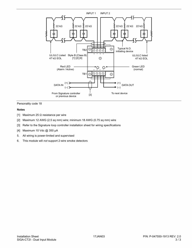
Installation Sheet 17JAN03 P/N: P-047550-1913 REV: 2.0SIGA-CT2I - Dual Input Module 3 / 3
(+)
(–)DATA OUT
UL/ULC Listed47 k EOLΩ
Style B (Class B)[1] [2] [4]
Red LED(Alarm / Active)
TB2
TB1
Typical N.O.initiating device
UL/ULC listed47 k EOLΩ
Green LED(normal)
(+)
(–)
From Signature controlleror previous device [3] To next device
DATA IN
1234
5678
INPUT 1 INPUT 2
22 kΩ 22 kΩ 22 kΩ 22 kΩ22 kΩ22 kΩ
Personality code 18
Notes
[1] Maximum 25 Ω resistance per wire
[2] Maximum 12 AWG (2.5 sq mm) wire; minimum 18 AWG (0.75 sq mm) wire
[3] Refer to the Signature loop controller installation sheet for wiring specifications
[4] Maximum 10 Vdc @ 350 µA
5. All wiring is power-limited and supervised
6. This module will not support 2-wire smoke detectors

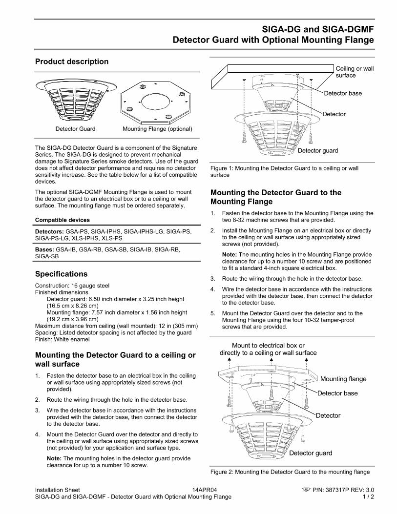
Installation Sheet 14APR04 P/N: 387317P REV: 3.0 SIGA-DG and SIGA-DGMF - Detector Guard with Optional Mounting Flange 1 / 2
SIGA-DG and SIGA-DGMF Detector Guard with Optional Mounting Flange
Product description
Detector Guard Mounting Flange (optional)
The SIGA-DG Detector Guard is a component of the Signature Series. The SIGA-DG is designed to prevent mechanical damage to Signature Series smoke detectors. Use of the guard does not affect detector performance and requires no detector sensitivity increase. See the table below for a list of compatible devices.
The optional SIGA-DGMF Mounting Flange is used to mount the detector guard to an electrical box or to a ceiling or wall surface. The mounting flange must be ordered separately.
Compatible devices
Detectors: GSA-PS, SIGA-IPHS, SIGA-IPHS-LG, SIGA-PS, SIGA-PS-LG, XLS-IPHS, XLS-PS
Bases: GSA-IB, GSA-RB, GSA-SB, SIGA-IB, SIGA-RB, SIGA-SB
Specifications Construction: 16 gauge steel Finished dimensions
Detector guard: 6.50 inch diameter x 3.25 inch height (16.5 cm x 8.26 cm) Mounting flange: 7.57 inch diameter x 1.56 inch height (19.2 cm x 3.96 cm)
Maximum distance from ceiling (wall mounted): 12 in (305 mm) Spacing: Listed detector spacing is not affected by the guard Finish: White enamel
Mounting the Detector Guard to a ceiling or wall surface 1. Fasten the detector base to an electrical box in the ceiling
or wall surface using appropriately sized screws (not provided).
2. Route the wiring through the hole in the detector base.
3. Wire the detector base in accordance with the instructions provided with the detector base, then connect the detector to the detector base.
4. Mount the Detector Guard over the detector and directly to the ceiling or wall surface using appropriately sized screws (not provided) for your application and surface type.
Note: The mounting holes in the detector guard provide clearance for up to a number 10 screw.
Ceiling or wallsurface
Detector guard
Detector base
Detector
Figure 1: Mounting the Detector Guard to a ceiling or wall surface
Mounting the Detector Guard to the Mounting Flange 1. Fasten the detector base to the Mounting Flange using the
two 8-32 machine screws that are provided.
2. Install the Mounting Flange on an electrical box or directly to the ceiling or wall surface using appropriately sized screws (not provided).
Note: The mounting holes in the Mounting Flange provide clearance for up to a number 10 screw and are positioned to fit a standard 4-inch square electrical box.
3. Route the wiring through the hole in the detector base.
4. Wire the detector base in accordance with the instructions provided with the detector base, then connect the detector to the detector base.
5. Mount the Detector Guard over the detector and to the Mounting Flange using the four 10-32 tamper-proof screws that are provided.
Mount to electrical box ordirectly to a ceiling or wall surface
Mounting flange
Detector guard
Detector base
Detector
Figure 2: Mounting the Detector Guard to the mounting flange
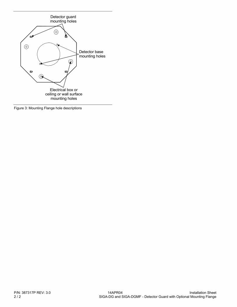
P/N: 387317P REV: 3.0 14APR04 Installation Sheet 2 / 2 SIGA-DG and SIGA-DGMF - Detector Guard with Optional Mounting Flange
Detector basemounting holes
Detector guardmounting holes
Electrical box orceiling or wall surface
mounting holes
Figure 3: Mounting Flange hole descriptions

INSTALLATION SHEET:
INSTALLATION SHEET P/N: 387318P FILE NAME: 387318(R1.0).CDR
SIGA-DGS Surface Adapter
SIGA-DG Detector Guardfor use with the
REVISION LEVEL: 1.0
CREATED BY: R W2DATE: 04/11/97
APPROVED BY: RR
GS BUILDING SYSTEMS, CORP.SARASOTA, FL. 941-739-4300 Fax: 941-753-1806CHESHIRE, CT. 203-699-3000 Fax: 203-699-3075OWEN SOUND, CANADA 519-376-2430 Fax: 519-376-7258INTERNATIONAL: CANADA 905-270-1711 Fax: 905-270-9553
PRODUCT INFORMATION
The model SIGA-DG Detector Guard is designed to preventmechanical damage to surface mounted Signature Seriessmoke detectors when used with the SIGA-DGS surfaceadapter. Use of the guard does not affect detectorperformance, and requires no detector sensitivity increase.
The guard is finished in white enamel, and secured withtamper-proof fasteners.
SPECIFICATIONS
Construction 16 gauge steel
DimensionsSurface Adapter 8.875" diameter x 2.25" height
(22.54cm x 5.71cm)
Adapter & Guard 8.875" diameter x 5.5" height(22.54cm x 13.97cm)
Compatible DevicesDetectors
Bases
Spacing Listed detector spacing is notaffected by the guard
Finish White enamel
SIGA-IPHS XLS-IPHSSIGA-PS XLS-PS GSA-PS
SIGA-IB GSA-IBSIGA-RB GSA-RBSIGA-SB GSA-SB
INSTALLATION
1. Install the SIGA-DGS surface adapter (A) over theelectrical box/conduit using appropriate fasteners.Mounting holes provide clearance for a #10 screw.
2. Fasten the detector base (C) to the SIGA-DGmounting flange (B) using the two #8-32 machinescrews provided.
3. Install the mounting flange and detector base (B & C)on surface adapter, using four #8 bolts provided.Route the base wiring through the hole in the base.
4. Wire the base in accordance with the instructionsprovided with the base, then install the detector (D).
5. Secure the guard cage (E) to the mounting flangeusing the four tamper-proof bolts provided, andtighten securely.

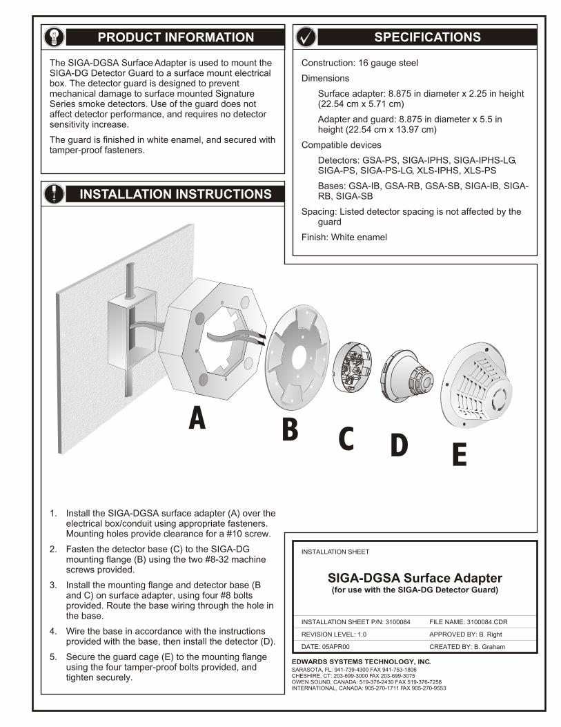
DATE: 05APR00
INSTALLATION SHEET
INSTALLATION SHEET P/N: 3100084
REVISION LEVEL: 1.0
FILE NAME: 3100084.CDR
CREATED BY: B. Graham
APPROVED BY: B. Right
PRODUCT INFORMATION SPECIFICATIONS
The SIGA-DGSA Surface Adapter is used to mount the SIGA-DG Detector Guard to a surface mount electrical box. The detector guard is designed to prevent mechanical damage to surface mounted Signature Series smoke detectors. Use of the guard does not affect detector performance, and requires no detector sensitivity increase.
The guard is finished in white enamel, and secured with tamper-proof fasteners.
INSTALLATION INSTRUCTIONS
Construction: 16 gauge steel
Dimensions
Surface adapter: 8.875 in diameter x 2.25 in height (22.54 cm x 5.71 cm)
Adapter and guard: 8.875 in diameter x 5.5 in height (22.54 cm x 13.97 cm)
Compatible devices
Detectors: GSA-PS, SIGA-IPHS, SIGA-IPHS-LG, SIGA-PS, SIGA-PS-LG, XLS-IPHS, XLS-PS
Bases: GSA-IB, GSA-RB, GSA-SB, SIGA-IB, SIGA-RB, SIGA-SB
Spacing: Listed detector spacing is not affected by the guard
Finish: White enamel
1. Install the SIGA-DGSA surface adapter (A) over the electrical box/conduit using appropriate fasteners. Mounting holes provide clearance for a #10 screw.
2. Fasten the detector base (C) to the SIGA-DG mounting flange (B) using the two #8-32 machine screws provided.
3. Install the mounting flange and detector base (B and C) on surface adapter, using four #8 bolts provided. Route the base wiring through the hole in the base.
4. Wire the base in accordance with the instructions provided with the base, then install the detector (D).
5. Secure the guard cage (E) to the mounting flange using the four tamper-proof bolts provided, and tighten securely.
SIGA-DGSA Surface Adapter(for use with the SIGA-DG Detector Guard)
EDWARDS SYSTEMS TECHNOLOGY, INC.SARASOTA, FL: 941-739-4300 FAX 941-753-1806CHESHIRE, CT: 203-699-3000 FAX 203-699-3075OWEN SOUND, CANADA: 519-376-2430 FAX 519-376-7258INTERNATIONAL, CANADA: 905-270-1711 FAX 905-270-9553
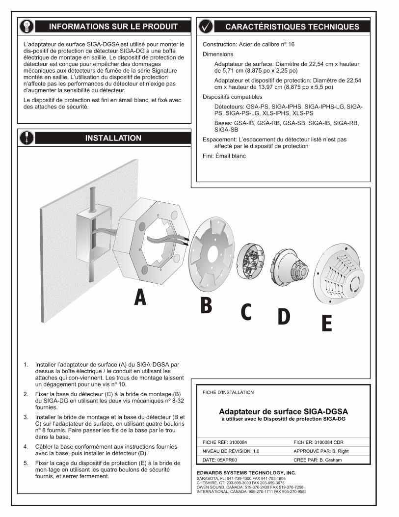
Adaptateur de surface SIGA-DGSAà utiliser avec le Dispositif de protection SIGA-DG
Construction: Acier de calibre nº 16
Dimensions
Adaptateur de surface: Diamètre de 22,54 cm x hauteur de 5,71 cm (8,875 po x 2,25 po)
Adaptateur et dispositif de protection: Diamètre de 22,54 cm x hauteur de 13,97 cm (8,875 po x 5,5 po)
Dispositifs compatibles
Détecteurs: GSA-PS, SIGA-IPHS, SIGA-IPHS-LG, SIGA-PS, SIGA-PS-LG, XLS-IPHS, XLS-PS
Bases: GSA-IB, GSA-RB, GSA-SB, SIGA-IB, SIGA-RB, SIGA-SB
Espacement: L’espacement du détecteur listé n’est pas affecté par le dispositif de protection
Fini: Émail blanc
INFORMATIONS SUR LE PRODUIT CARACTÉRISTIQUES TECHNIQUES
INSTALLATION
L’adaptateur de surface SIGA-DGSA est utilisé pour monter le dis-positif de protection de détecteur SIGA-DG à une boîte électrique de montage en saillie. Le dispositif de protection de détecteur est conçue pour empêcher des dommages mécaniques aux détecteurs de fumée de la série Signature montés en saillie. L’utilisation du dispositif de protection n’affecte pas les performances du détecteur et n’exige pas d’augmenter la sensibilité du détecteur.
Le dispositif de protection est fini en émail blanc, et fixé avec des attaches de sécurité.
1. Installer l’adaptateur de surface (A) du SIGA-DGSA par dessus la boîte électrique / le conduit en utilisant les attaches qui con-viennent. Les trous de montage laissent un dégagement pour une vis nº 10.
2. Fixer la base du détecteur (C) à la bride de montage (B) du SIGA-DG en utilisant les deux vis mécaniques nº 8-32 fournies.
3. Installer la bride de montage et la base du détecteur (B et C) sur l’adaptateur de surface, en utilisant quatre boulons nº 8 fournis. Faire passer les fils de la base par le trou dans la base.
4. Câbler la base conformément aux instructions fournies avec la base, puis installer le détecteur (D).
5. Fixer la cage du dispositif de protection (E) à la bride de mon-tage en utilisant les quatre boulons de sécurité fournis, et serrer fermement.
FICHE D’INSTALLATION
FICHE RÉF: 3100084 FICHIER: 3100084.CDR
NIVEAU DE RÉVISION: 1.0 APPROUVÉ PAR: B. Right
CRÉÉ PAR: B. GrahamDATE: 05APR00
EDWARDS SYSTEMS TECHNOLOGY, INC.SARASOTA, FL: 941-739-4300 FAX 941-753-1806CHESHIRE, CT: 203-699-3000 FAX 203-699-3075OWEN SOUND, CANADA: 519-376-2430 FAX 519-376-7258INTERNATIONAL, CANADA: 905-270-1711 FAX 905-270-9553
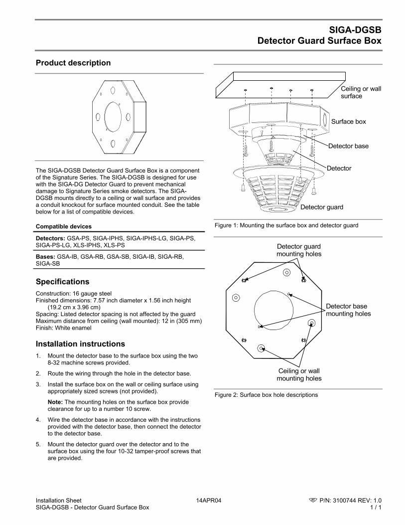
Installation Sheet 14APR04 P/N: 3100744 REV: 1.0 SIGA-DGSB - Detector Guard Surface Box 1 / 1
SIGA-DGSB Detector Guard Surface Box
Product description
The SIGA-DGSB Detector Guard Surface Box is a component of the Signature Series. The SIGA-DGSB is designed for use with the SIGA-DG Detector Guard to prevent mechanical damage to Signature Series smoke detectors. The SIGA-DGSB mounts directly to a ceiling or wall surface and provides a conduit knockout for surface mounted conduit. See the table below for a list of compatible devices.
Compatible devices
Detectors: GSA-PS, SIGA-IPHS, SIGA-IPHS-LG, SIGA-PS, SIGA-PS-LG, XLS-IPHS, XLS-PS
Bases: GSA-IB, GSA-RB, GSA-SB, SIGA-IB, SIGA-RB, SIGA-SB
Specifications Construction: 16 gauge steel Finished dimensions: 7.57 inch diameter x 1.56 inch height
(19.2 cm x 3.96 cm) Spacing: Listed detector spacing is not affected by the guard Maximum distance from ceiling (wall mounted): 12 in (305 mm) Finish: White enamel
Installation instructions 1. Mount the detector base to the surface box using the two
8-32 machine screws provided.
2. Route the wiring through the hole in the detector base.
3. Install the surface box on the wall or ceiling surface using appropriately sized screws (not provided).
Note: The mounting holes on the surface box provide clearance for up to a number 10 screw.
4. Wire the detector base in accordance with the instructions provided with the detector base, then connect the detector to the detector base.
5. Mount the detector guard over the detector and to the surface box using the four 10-32 tamper-proof screws that are provided.
Ceiling or wallsurface
Surface box
Detector guard
Detector base
Detector
Figure 1: Mounting the surface box and detector guard
Detector basemounting holes
Detector guardmounting holes
Ceiling or wallmounting holes
Figure 2: Surface box hole descriptions

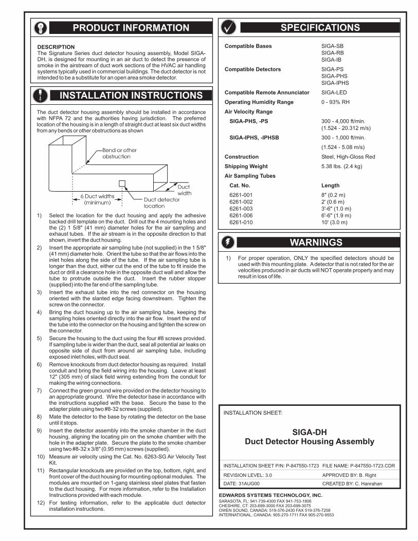
DATE: 31AUG00
FILE NAME: P-847550-1723.CDR
REVISION LEVEL: 3.0
CREATED BY: C. Hanrahan
APPROVED BY: B. Right
SIGA-DHDuct Detector Housing Assembly
INSTALLATION SHEET:
PRODUCT INFORMATION
DESCRIPTIONThe Signature Series duct detector housing assembly, Model SIGA-DH, is designed for mounting in an air duct to detect the presence ofsmoke in the airstream of duct work sections of the HVAC air handlingsystems typically used in commercial buildings. The duct detector is notintended to be a substitute for an open area smoke detector.
1) For proper operation, ONLY the specified detectors should beused with this mounting plate. Adetector that is not rated for the airvelocities produced in air ducts will NOT operate properly and mayresult in loss of life.
SPECIFICATIONS
Compatible Bases
Compatible Detectors
Compatible Remote Annunciator
Operating Humidity Range
Air Velocity Range
SIGA-PHS, -PS
SIGA-IPHS, -IPHSB
Construction
Shipping Weight
Air Sampling Tubes
Cat. No. Length
SIGA-SBSIGA-RBSIGA-IB
SIGA-PSSIGA-PHSSIGA-IPHS
SIGA-LED
0 - 93% RH
300 - 4,000 ft/min.(1.524 - 20.312 m/s)
300 - 1,000 ft/min.
(1.524 - 5.08 m/s)
Steel, High-Gloss Red
5.38 lbs. (2.4 kg)
6261-001 8" (0.2 m)6261-002 2' (0.6 m)6261-003 3'-6" (1.0 m)6261-006 6'-6" (1.9 m)6261-010 10' (3.0 m)
NOTE
INSTALLATION INSTRUCTIONS
The duct detector housing assembly should be installed in accordancewith NFPA 72 and the authorities having jurisdiction. The preferredlocation of the housing is in a length of straight duct at least six duct widthsfrom any bends or other obstructions as shown
WARNINGS
INSTALLATION SHEET P/N: P-847550-1723
1) Select the location for the duct housing and apply the adhesivebacked drill template on the duct. Drill out the 4 mounting holes andthe (2) 1 5/8" (41 mm) diameter holes for the air sampling andexhaust tubes. If the air stream is in the opposite direction to thatshown, invert the duct housing.
2) Insert the appropriate air sampling tube (not supplied) in the 1 5/8"(41 mm) diameter hole. Orient the tube so that the air flows into theinlet holes along the side of the tube. If the air sampling tube islonger than the duct, either cut the end of the tube to fit inside theduct or drill a clearance hole in the opposite duct wall and allow thetube to protrude outside the duct. Insert the rubber stopper(supplied) into the far end of the sampling tube.
3) Insert the exhaust tube into the red connector on the housingoriented with the slanted edge facing downstream. Tighten thescrew on the connector.
4) Bring the duct housing up to the air sampling tube, keeping thesampling holes oriented directly into the air flow. Insert the end ofthe tube into the connector on the housing and tighten the screw onthe connector.
5) Secure the housing to the duct using the four #8 screws provided.If sampling tube is wider than the duct, seal all potential air leaks onopposite side of duct from around air sampling tube, includingexposed inlet holes, with duct seal.
6) Remove knockouts from duct detector housing as required. Installconduit and bring the field wiring into the housing. Leave at least12" (305 mm) of slack field wiring extending from the conduit formaking the wiring connections.
7) Connect the green ground wire provided on the detector housing toan appropriate ground. Wire the detector base in accordance withthe instructions supplied with the base. Secure the base to theadapter plate using two #8-32 screws (supplied).
8) Mate the detector to the base by rotating the detector on the baseuntil it stops.
9) Insert the detector assembly into the smoke chamber in the ducthousing, aligning the locating pin on the smoke chamber with thehole in the adapter plate. Secure the plate to the smoke chamberusing two #8-32 x 3/8" (0.95 mm) screws (supplied).
10) Measure air velocity using the Cat. No. 6263-SG Air Velocity TestKit.
11) Rectangular knockouts are provided on the top, bottom, right, andfront cover of the duct housing for mounting optional modules. Themodules are mounted on 1-gang stainless steel plates that fastento the duct housing. For more information, refer to the InstallationInstructions provided with each module.
12) For testing information, refer to the applicable duct detectorinstallation instructions.
EDWARDS SYSTEMS TECHNOLOGY, INC.SARASOTA, FL: 941-739-4300 FAX 941-753-1806CHESHIRE, CT: 203-699-3000 FAX 203-699-3075OWEN SOUND, CANADA: 519-376-2430 FAX 519-376-7258INTERNATIONAL, CANADA: 905-270-1711 FAX 905-270-9553
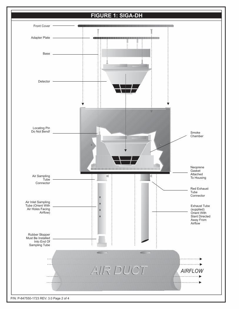
P/N: P-847550-1723 REV: 3.0 Page 2 of 4
FIGURE 1: SIGA-DH
NeopreneGasketAttachedTo Housing
Locating PinDo Not Bend!
Exhaust Tube(supplied)Orient WithSlant DirectedAway FromAirflow
Red ExhaustTubeConnector
Air SamplingTube
Connector
AIR DUCTAIR DUCT
SmokeChamber
Detector
Front Cover
Adapter Plate
Base
AIR DUCT AIRFLOW
Rubber StopperMust Be Installed
Into End OfSampling Tube
Air Inlet SamplingTube (Orient WithAir Holes Facing
Airflow)
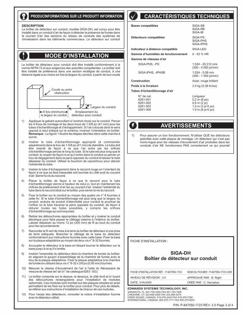
DATE: 31AUG00
NOM DU FICHIER : P-847550-1723.CDR
NIVEAU DE RÉVISION : 3.0
CRÉÉ PAR : C. Hanrahan
APPROUVÉ PAR : B. Right
SIGA-DHBoîtier de détecteur sur conduit
FICHE D’INSTALLATION :
PRODUC T INFORMATIONINFORMATIONS SUR LE PRODUIT
DESCRIPTIONLe boîtier de détecteur sur conduit, modèle SIGA-DH, est conçu pour êtreinstallé dans un conduit d’air de façon à détecter la présence de fumée dansle courant d’air des sections du réseau de conduits des systèmes declimatisation dans les bâtiments commerciaux. Le détecteur sur conduit
1) Pour assurer un bon fonctionnement, N’utiliser QUE les détecteursspécifiés avec cette plaque de montage. Un détecteur qui n’est pashomo-logué pour les vitesses d’écoulement d’air produites dans lesconduits d’air NE fonctionnera PAS correctement ce qui pourrait
CARACTÉRISTIQUES TECHNIQUES
Bases compatibles
Détecteurs compatibles
Indicateur à distance compatible
Gamme d’humidités de fonctionnement
Gamme de vitesses d’air
Construction
Poids à la livraison
Tubes d’échantillonnage d’air
SIGA-SBSIGA-RBSIGA-IB
SIGA-PSSIGA-PHSSIGA-IPHS
SIGA-LED
0 - 93 % HR
SIGA-PHS, -PS 1,524 - 20,312 m/s(300 - 4 000 pi/min)
SIGA-IPHS, -IPHSB 1,524 - 5,08 m/s(300 - 1 000 pi/min)
Acier, rouge brillant
2,4 kg (5,38 livres)
N de cat. Longueur6261-001 0,2 m (8 po)6261-002 0,6 m (2 pi)6261-003 1,0 m (3 pi 6 po)6261-006 1,9 m (6 pi 6 po)
°
NOTE
MODE D’INSTALLATION
Le boîtier de détecteur pour conduit doit être installé conformément à lanorme NFPA 72 et aux exigences des autorités compétentes. Le boîtier doitêtre installé de préférence dans une section rectiligne de conduit, à unedistance égale à au moins six fois la largeur du conduit, à partir de tout coude
AVERTISSEMENTS
FICHE D’INSTALLATION RÉF. : P-847550-1723
1) Appliquer le gabarit autocollant à l’endroit choisi sur le conduit. Percerles 4 trous de montage et les deux trous de 1-5/8 po (41 mm) pour lestubes d’échantillonage et d’échappement. Si l’air s écoule dans le sensopposé à celui indiqué sur le schéma, inverser l’orientation du boîtier.
: La figure 1 illustre les étapes décrites dans cette marche àsuivre.
2) Insérer le tube d’échantillonnage approprié (à commanderséparément) dans le trou de 1-5/8 po (41 mm) de diamètre. Le tube doitêtre orienté de façon à ce que l’air entre par les orificesd’échantillonnage percés le long du tube. Si le tube est plus long que leconduit, le couper de façon à ce qu il entre dans le conduit ou percer untrou de dégagement dans la paroi opposée du conduit et laisser le tubedépasser du conduit. Utiliser le bouchon de caoutchouc pour obturerl’extrémité du tube.
3) Insérer le tube d’échappement dans le raccord rouge en l’orientant defaçon à ce que sa face biseautée soit tournée du côté aval du courantd’air. Serrer la vis du raccord.
4) Placer le boîtier de façon à ce que le raccord pour le tubed’échantillonnage vienne à hauteur de celui-ci, tout en maintenant lesorifices de prélèvement d’air fac au courant d’air. Insérer l’extrémité dutube dans le raccord situé sur le boîtier, puis serrer la vis du raccord.
5) Fixer le boîtier sur le conduit au moyen des quatre vis n 8 fournies àcette fin. Si le tube d’échantillonnage est plus long que la largeur duconduit, enduire de produit d’étanchéité pour conduit le pourtout del’orifice où le tube traverse la paroi opposée du conduit, de façon àobturer toutes les fuites possibles, y compris les orificesd’échantillonnage qui sont exposés.
6) Retirer les débouchures appropriées du boîtier et y insérer le conduitélectrique pour faire passer le câblage externe à l’intérirur du boîtier.Laisser dépasser au moins 12 po (305 mm) de fil au bout du conduitpour les raccordements.
7) Raccorder le fil vert de mise à la terre du boîtier de détecteur à une prisede terre adéquate. Brancher le câblage de la base du détecteurconformément aux instructions fournies avec cette base. Fixer la basesur la plaque adaptatrice au moyen de deux vis n 8-32 fournies.
8) Accoupler le détecteur à la base en faisant tourner le détecteur sur labase jusqu’à ce qu’il s’arrête.
9) Insérer l’ensemble du détecteur dans la chambre de fumée du boîtier,en alignant le goujon d’assemblage de la chambre de fumée avec letrou de la plaque adaptatrice. Fixer la plaque adaptatrice à la chambrede fumée en utilisant deux vis n 8-32 x 3/8 po (0,95 mm) fournies.
10) Mesurer la vitesse d’écoulement de l’air à l’aide du Nécessaire demesure de vitesse de l’air (n de catalogue 6263 - SG).
11) Le boîtier comporte sur le dessus, le dessous, le côté droit et à l’avantdes débouchures rectangulaires pour l’installation de modulesoptionnels. Ces modules sont montés sur des plaques simples en acierpermettant de les fixer sur le boîtier pour conduit. Pour plus de détails,se référer aux instructions d’installation de chacun de ces modules.
12) Pour l’essai des détecteurs, consulter la notice d’installation fournieavec le détecteur utilisé.
Remarque
°
°
°
°
Coude ou autreobstruction
6 fois (minimum)la largeur du conduit
Emplacement dudétecteur pour conduit
Largeur du conduit
P/N: P-847550-1723 REV: 3.0 Page 3 of 4
EDWARDS SYSTEMS TECHNOLOGY, INC.SARASOTA, FL: 941-739-4300 FAX 941-753-1806CHESHIRE, CT: 203-699-3000 FAX 203-699-3075OWEN SOUND, CANADA: 519-376-2430 FAX 519-376-7258INTERNATIONAL, CANADA: 905-270-1711 FAX 905-270-9553
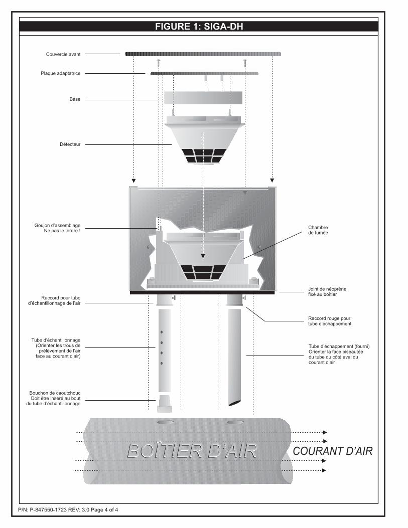
P/N: P-847550-1723 REV: 3.0 Page 4 of 4
FIGURE 1: SIGA-DH
Joint de néoprènefixé au boîtier
Goujon d’assemblageNe pas le tordre !
Tube d’échappement (fourni)Orienter la face biseautéedu tube du côté aval ducourant d’air
Raccord rouge pourtube d’échappement
Raccord pour tubed’échantillonnage de l’air
BOÎTIER D’AIRBOÎTIER D’AIR
Chambrede fumée
Détecteur
Couvercle avant
Plaque adaptatrice
Base
BOÎTIER D’AIR COURANT D’AIR
Bouchon de caoutchoucDoit être inséré au bout
du tube d’échantillonnage
Tube d’échantillonnage(Orienter les trous de
prélèvement de l’airface au courant d’air)
FIGURE 1 : SIGA-DH
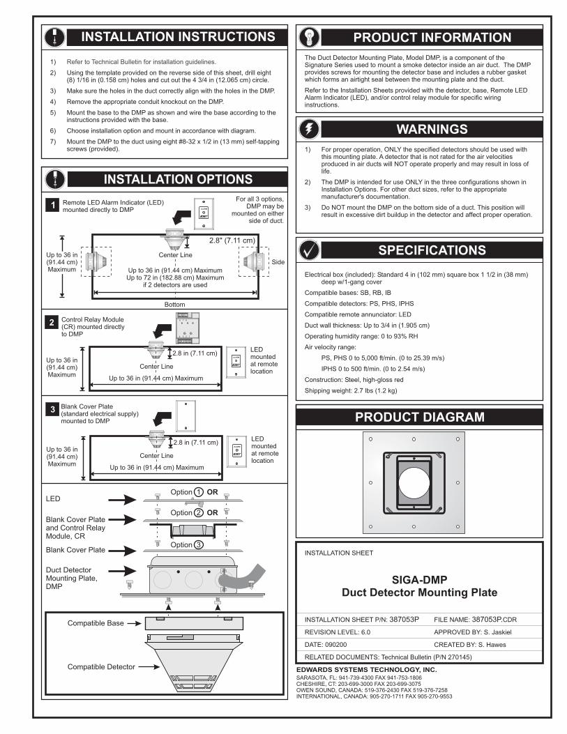
Electrical box (included): Standard 4 in (102 mm) square box 1 1/2 in (38 mm)deep w/1-gang cover
Compatible bases: SB, RB, IB
Compatible detectors: PS, PHS, IPHS
Compatible remote annunciator: LED
Duct wall thickness: Up to 3/4 in (1.905 cm)
Operating humidity range: 0 to 93% RH
Air velocity range:
PS, PHS 0 to 5,000 ft/min. (0 to 25.39 m/s)
IPHS 0 to 500 ft/min. (0 to 2.54 m/s)
Construction: Steel, high-gloss red
Shipping weight: 2.7 lbs (1.2 kg)
INSTALLATION INSTRUCTIONS
PRODUCT DIAGRAM
DATE: 090200
INSTALLATION SHEET
INSTALLATION SHEET P/N: 387053P
REVISION LEVEL: 6.0
FILE NAME: CDR387053P.
CREATED BY: S. Hawes
APPROVED BY: S. Jaskiel
EDWARDS SYSTEMS TECHNOLOGY, INC.SARASOTA, FL: 941-739-4300 FAX 941-753-1806CHESHIRE, CT: 203-699-3000 FAX 203-699-3075OWEN SOUND, CANADA: 519-376-2430 FAX 519-376-7258INTERNATIONAL, CANADA: 905-270-1711 FAX 905-270-9553
1)
2) Using the template provided on the reverse side of this sheet, drill eight(8) 1/16 in (0.158 cm) holes and cut out the 4 3/4 in (12.065 cm) circle.
3) Make sure the holes in the duct correctly align with the holes in the DMP.
4) Remove the appropriate conduit knockout on the DMP.
5) Mount the base to the DMP as shown and wire the base according to theinstructions provided with the base.
6) Choose installation option and mount in accordance with diagram.
7) Mount the DMP to the duct using eight #8-32 x 1/2 in (13 mm) self-tappingscrews (provided).
Refer to Technical Bulletin for installation guidelines.
Compatible Detector
Compatible Base
Duct DetectorMounting Plate,DMP
LED
Blank Cover Plateand Control RelayModule, CR
Blank Cover PlateOption 3
Option 2 OR
Option 1 OR
INSTALLATION OPTIONSFor all 3 options,
DMP may bemounted on either
side of duct.
Installation OptionsRemote LED Alarm Indicator (LED)mounted directly to DMP
1
2.8" (7.11 cm)
Up to 36 in(91.44 cm)Maximum
Side
Bottom
Center Line
Up to 36 in (91.44 cm) MaximumUp to 72 in (182.88 cm) Maximum
if 2 detectors are used
ALARM
8
4
7 6
3 2 1
Control Relay Module(CR) mounted directlyto DMP
2
LEDmountedat remotelocation
ALARM
2.8 in (7.11 cm)Up to 36 in(91.44 cm)Maximum
Center Line
Up to 36 in (91.44 cm) Maximum
Blank Cover Plate(standard electrical supply)mounted to DMP
3
LEDmountedat remotelocation
ALARM
2.8 in (7.11 cm)Up to 36 in(91.44 cm)Maximum
Center Line
Up to 36 in (91.44 cm) Maximum
PRODUCT INFORMATIONThe Duct Detector Mounting Plate, Model DMP, is a component of theSignature Series used to mount a smoke detector inside an air duct. The DMPprovides screws for mounting the detector base and includes a rubber gasketwhich forms an airtight seal between the mounting plate and the duct.
Refer to the Installation Sheets provided with the detector, base, Remote LEDAlarm Indicator (LED), and/or control relay module for specific wiringinstructions.
WARNINGS1) For proper operation, ONLY the specified detectors should be used with
this mounting plate. A detector that is not rated for the air velocitiesproduced in air ducts will NOT operate properly and may result in loss oflife.
2) The DMP is intended for use ONLY in the three configurations shown inInstallation Options. For other duct sizes, refer to the appropriatemanufacturer's documentation.
3) Do NOT mount the DMP on the bottom side of a duct. This position willresult in excessive dirt buildup in the detector and affect proper operation.
SPECIFICATIONS
SIGA-DMPDuct Detector Mounting Plate
RELATED DOCUMENTS: Technical Bulletin (P/N 270145)
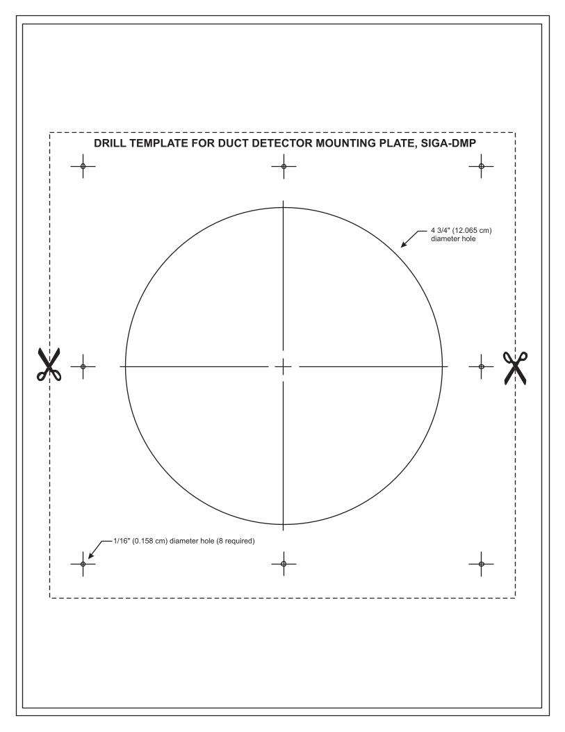
1/16" (0.158 cm) diameter hole (8 required)
4 3/4" (12.065 cm)diameter hole
DRILL TEMPLATE FOR DUCT DETECTOR MOUNTING PLATE, SIGA-DMP
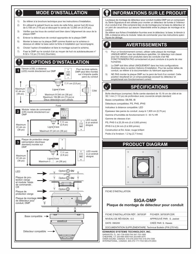
PRODUCT DIAGRAM
DATE: 090200
FICHE D’INSTALLATION
FICHE D’INSTALLATION RÉF.: 387053P
NIVEAU DE RÉVISION : 6.0
FICHIER: 387053P.CDR
CRÉÉ PAR: S. Hawes
APPROUVÉ PAR: S. Jaskiel
EDWARDS SYSTEMS TECHNOLOGY, INC.SARASOTA, FL: 941-739-4300 FAX 941-753-1806CHESHIRE, CT: 203-699-3000 FAX 203-699-3075OWEN SOUND, CANADA: 519-376-2430 FAX 519-376-7258INTERNATIONAL, CANADA: 905-270-1711 FAX 905-270-9553
DOCUMENTATION SUPPLÉMENTAIRE: Technical Bulletin (P/N 270145)
MODE D’INSTALLATION
1) Se référer à la brochure technique pour les instructions d’installation.
2) En utilisant le gabarit fourni au recto de cette fiche, percer huit (8) trousde 0,158 cm (1/16 po) et découper le cercle de 12,065 cm (4-3/4 po).
3) Vérifier que les trous de conduit sont bien dans l’alignement de ceux de laplaque DMP.
4) Enlever la débouchure de conduit appropriée de la plaque DMP.
5) Monter la base sur la plaque DMP comme illustré sur le schéma ci-dessous et câbler la base selon la fiche d installation qui l’accompagne.
6) Choisir l’option d’installation et faire le montage suivant le schéma.
7) Fixer le DMP sur le conduit d’air au moyen de huit vis autotaraudeuses n8-32 x 1/2 po (13 mm) (fournies).
°
OPTIONS D’INSTALLATION
1ALARM
7,11 cm (2,8 po)
Ligne d’axe
Maximum 91,44 cm (36 po)Maximum 182,88 cm (72 po) si
étecteurs sont utilisésDeux d
Maximum91,44 cm(36 po)
Témoin à DEL à distance(LED) monté directement sur DMP
Pour les trois options,DMP peut être montée
sur n’importe quelleparoi du conduit
Côté
Fond
Maximum91,44 cm(36 po)
8
4
7 6
3 2 1
2
ALARM
7,11 cm(2,8 po)
Ligne d’axe
Maximum 91,44 cm (36 po)
Module ‘relais de commande’(CR) monté directement surDMP
LED montéà un endroitéloigné
Maximum91,44 cm(36 po)
3Plaque de protection vierge(alimentation électriquestandard) montée surDMP
Maximum 91,44 cm (36 po)Ligne d’axe
7,11 cm(2,8 po)
ALARM
LED montéà un endroitéloigné
Détecteur compatible
Base compatible
Plaque de montagede détecteur pourconduit, DMP
LED
Plaque de pro-tection viergeet module ‘relaisde commande’,CR
Plaque deprotection vierge
Option 3
Option 2 OU
Option 1 OU
INFORMATIONS SUR LE PRODUITLa plaque de montage de détecteur pour conduit modèle DMP est un composantdu Série Signature et est utilisée pour monter un détecteur de fumée à l’intérieurd’un conduit d’air. Elle comprend des vis de montage pour la base du détecteur etun joint de caoutchouc qui assure l’étanchéité entre la plaque de montage et leconduit.Se référer aux fiches d’installation fournies avec le détecteur, la base, le témoin àDEL à distance et/ou le module ‘relais de commande’ pour les instructions spéci-fiques de câblage.
AVERTISSEMENTS1) Pour un fonctionnement correct, utiliser cette plaque de montage
UNIQUE-MENT avec les détecteurs spécifiés. Un détecteur non classépour les vitesses d’air produites dans les conduits d’air NEFONCTIONNERA PAS correctement et peut conduire à la perte de vieshumaines.
2) Le DMP doit être utilisé UNIQUEMENT dans les trois configurationsillustrées dans la section Options d’installation. Pour les autres tailles deconduit, se référer à la documentation du fabricant appropriée.
3) NE PAS monter la plaque DMP sur la paroi de fond d’un conduit. Cetteposition résulterait en un empoussièrage excessif du détecteur etempêcherait son fonctionnement correct.
SPÉCIFICATIONSBoîte électrique (comprise): Boîte carrée standard de 10,16 cm de côté et de38,1 mm (1-1/2 po) de profondeur avec couvercle simple standard
Bases compatibles: SB,RB, IB
Détecteurs compatibles: PS, PHS, IPHS
Indicateur à distance compatible: LED
Épaisseur des parois du conduit: Jusqu’à 1,905 cm (0,75 po)
Gamme d’humidités de fonctionnement: 0 - 93 % HR
Gamme de vitesses d’air:
PS, PHS 0 à 25,39 m/s (0 à 5,000 pi/min)
IPHS 0 à 2,54 m/s (0 à 500 pi/min)
Construction et fini: Acier, rouge brillant
Poids à la livraison: 1,2 kg (2,7 livres)
SIGA-DMPPlaque de montage de détecteur pour conduit
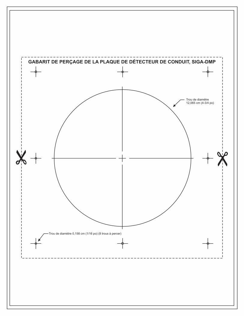
Trou de diamètre 0,158 cm (1/16 po) (8 trous à percer)
Trou de diamètre12,065 cm (4-3/4 po)
GABARIT DE PERÇAGE DE LA PLAQUE DE DÉTECTEUR DE CONDUIT, SIGA-DMP
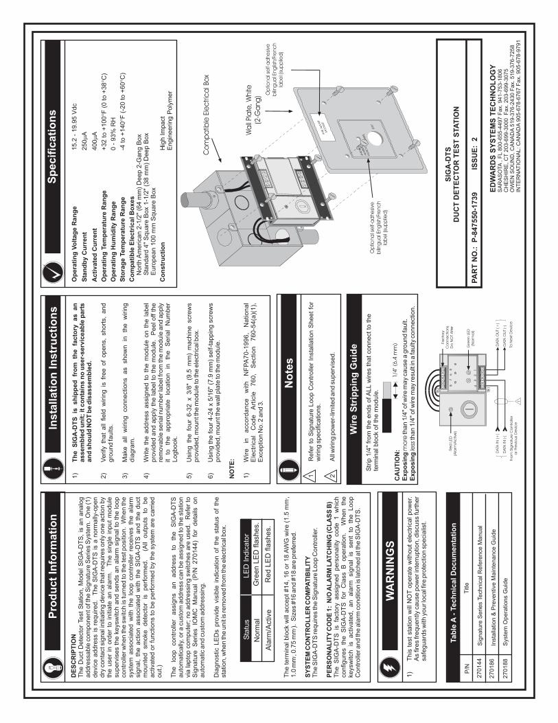
Pro
du
ctIn
form
atio
nIn
stal
lati
on
Inst
ruct
ion
s
WA
RN
ING
S
No
tes
Sp
ecif
icat
ion
s
Tab
leA
-Te
chn
ical
Do
cum
enta
tio
n
P/N
Titl
e
Sig
natu
reS
eries
Tech
nic
alR
efe
rence
Manual
Inst
alla
tion
&P
reve
ntiv
eM
ain
tenance
Guid
e
Sys
tem
Opera
tions
Guid
e
270144
270186
270188
ED
WA
RD
SS
YS
TE
MS
TE
CH
NO
LO
GY
SA
RA
SO
TA,
FL
80
0-6
55
-44
97
Fa
x.9
41
-75
3-1
80
6C
HE
SH
IRE
,C
T2
03
-69
9-3
00
0F
ax.
20
3-6
99
-30
75
OW
EN
SO
UN
D,
CA
NA
DA
51
9-3
76
-24
30
Fa
x.5
19
-37
6-7
25
8IN
TE
RN
AT
ION
AL
:C
AN
AD
A9
05
-67
8-6
76
7F
ax.
90
5-6
78
-97
91
SIG
A-D
TS
DU
CT
DE
TE
CT
OR
TE
ST
STA
TIO
N
PA
RT
NO
.:P
-847
550-
1739
ISS
UE
:2
DE
SC
RIP
TIO
NT
he
Duct
Dete
ctor
Test
Sta
tion,
Model
SIG
A-D
TS
,is
an
analo
gaddre
ssable
com
ponento
fthe
Sig
natu
reS
eries
Sys
tem
.O
ne
(1)
devi
ceaddre
ssis
required.
The
SIG
A-D
TS
isa
norm
ally
-open
dry
conta
ctsi
gnali
niti
atin
gdevi
ceth
atr
equires
only
one
act
ion
by
the
use
rin
ord
er
toin
itiate
an
ala
rm.
The
single
input
module
superv
ises
the
keys
witc
hand
sends
an
ala
rmsi
gnalt
oth
elo
op
contr
olle
rwhen
the
switc
his
turn
ed
toth
ete
stposi
tion.
When
the
syst
em
ass
oci
ate
dw
ithth
elo
op
contr
olle
rre
ceiv
es
the
ala
rmsi
gnal,
the
act
ion
ass
oci
ate
dw
ithth
eS
IGA
-DT
Sand
the
duct
mounte
dsm
oke
dete
ctor
isperf
orm
ed.
(All
outp
uts
tobe
act
ivate
dor
funct
ions
tobe
perf
orm
ed
by
the
syst
em
are
carr
ied
out.)
The
loop
contr
olle
rass
igns
an
addre
ssto
the
SIG
A-D
TS
auto
matic
ally
,ora
cust
om
addre
ssca
nbe
ass
igned
toth
est
atio
nvi
ala
pto
pco
mpute
r;no
addre
ssin
gsw
itches
are
use
d.
Refe
rto
Sig
natu
reS
eries
IOM
CM
anual
(P/N
270144)
for
deta
ilson
auto
matic
and
cust
om
addre
ssin
g.
Dia
gnost
icLE
Ds
pro
vide
visi
ble
indic
atio
nof
the
statu
sof
the
statio
n,w
hen
the
unit
isre
move
dfr
om
the
ele
ctrica
lbox.
The
term
inalb
lock
will
acc
ept
#14,
16
or
18
AW
Gw
ire
(1.5
mm
,1.0
mm
,0.7
5m
m).
Siz
es
#16
and
#18
are
pre
ferr
ed.
The
SIG
A-D
TS
requires
the
Sig
natu
reLoop
Contr
olle
r.
The
SIG
A-D
TS
isfa
ctory
ass
igned
pers
onalit
yco
de
1w
hic
hco
nfig
ure
sth
eS
IGA
-DT
Sfo
rC
lass
Bopera
tion.
When
the
keys
witc
his
act
ivate
d,
an
ala
rmsi
gnal
isse
nt
toth
eLoop
Contr
olle
rand
the
ala
rmco
nditi
on
isla
tched
att
he
SIG
A-D
TS
.
2
22
SY
ST
EM
CO
NT
RO
LL
ER
CO
MP
AT
IBIL
ITY
PE
RS
ON
AL
ITY
CO
DE
1:N
/OA
LA
RM
LA
TC
HIN
G(C
LA
SS
B)
Sta
tus
LE
DIn
dic
ato
r
Norm
al
Ala
rm/A
ctiv
e
Gre
en
LE
Dfla
shes.
Red
LE
Dfla
shes.
1)
This
test
statio
nw
illN
OT
opera
tew
ithout
ele
ctrica
lpow
er.
As
fires
frequently
cause
pow
eri
nte
rruptio
n,d
iscu
ssfu
rther
safe
guard
sw
ithyo
url
oca
lfire
pro
tect
ion
speci
alis
t.
1)
2)
Verify
that
all
field
wirin
gis
free
of
opens,
short
s,and
gro
und
faults
.
3)
Make
all
wirin
gco
nnect
ions
as
show
nin
the
wirin
gdia
gra
m.
4)
Write
the
addre
ssass
igned
toth
em
odule
on
the
label
pro
vided
and
apply
the
labelt
oth
em
odule
.P
eelo
ffth
ere
mova
ble
serialn
um
berl
abelf
rom
the
module
and
apply
itto
the
appro
priate
loca
tion
inth
eS
erial
Num
ber
Logbook.
5)
Usi
ng
the
four
6-3
2x
3/8
"(9
.5m
m)
mach
ine
scre
ws
pro
vided,m
ountt
he
module
toth
eele
ctrica
lbox.
6)
Usi
ng
the
four
4-2
4x
5/1
6"
(7.9
mm
)se
lf-ta
ppin
gsc
rew
spro
vided,m
ountt
he
wall
pla
teto
the
module
.
1)
Wir
ein
acc
ord
an
cew
ithN
FP
A7
0-1
99
6,
Na
tion
al
Ele
ctri
cal
Co
de
Art
icle
76
0,
Se
ctio
n7
60
-54
(a)(
1),
Exc
eptio
nN
o.2
and
3.
Th
eS
IGA
-DT
Sis
ship
ped
fro
mth
efa
cto
ryas
anas
sem
ble
du
nit
;it
con
tain
sn
ou
ser-
serv
icea
ble
par
tsan
dsh
ou
ldN
OT
be
dis
asse
mb
led
.
NO
TE
:
1R
efe
rto
Sig
natu
reLoop
Contr
olle
rIn
stalla
tion
Sheet
for
wirin
gsp
eci
ficatio
ns.
2A
llw
irin
gpow
er-
limite
dand
superv
ised.
Wir
eS
trip
pin
gG
uid
e
Str
ip1/4
"fr
om
the
ends
ofA
LL
wires
thatco
nnect
toth
ete
rmin
alb
lock
ofth
em
odule
.
CA
UT
ION
:E
xpo
sin
gE
xpo
sin
gm
ore
less
than
1/4
"ofw
ire
may
cause
agro
und
fault.
than
1/4
"ofw
ire
may
resu
ltin
afa
ulty
connect
ion.
Op
erat
ing
Vo
ltag
eR
ang
e
Sta
nd
by
Cu
rren
t
Act
ivat
edC
urr
ent
Op
erat
ing
Tem
per
atu
reR
ang
e
Op
erat
ing
Hu
mid
ity
Ran
ge
Sto
rag
eTe
mp
erat
ure
Ran
ge
Co
mp
atib
leE
lect
rica
lBo
xes
Co
nst
ruct
ion
15.2
-19.9
5V
dc
250
A
400
A
+32
to+
100
F(0
to+
38
C)
0-
93%
RH
-4to
+140
F(-
20
to+
60
C)
Nort
hA
merica
n2-1
/2"
(64
mm
)D
eep
2-G
ang
Box
Sta
ndard
4"
Square
Box
1-1
/2"
(38
mm
)D
eep
Box
Euro
pean
100
mm
Square
Box
Hig
hIm
pact
Engin
eering
Poly
mer
°°
°°

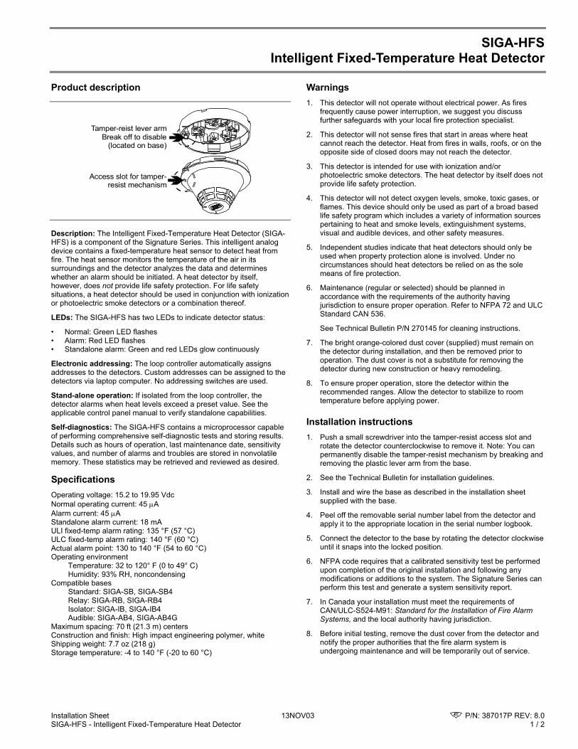
Installation Sheet 13NOV03 P/N: 387017P REV: 8.0 SIGA-HFS - Intelligent Fixed-Temperature Heat Detector 1 / 2
SIGA-HFS Intelligent Fixed-Temperature Heat Detector
Product description
Tamper-reist lever armBreak off to disable
(located on base)
Access slot for tamper-resist mechanism
Description: The Intelligent Fixed-Temperature Heat Detector (SIGA-HFS) is a component of the Signature Series. This intelligent analog device contains a fixed-temperature heat sensor to detect heat from fire. The heat sensor monitors the temperature of the air in its surroundings and the detector analyzes the data and determines whether an alarm should be initiated. A heat detector by itself, however, does not provide life safety protection. For life safety situations, a heat detector should be used in conjunction with ionization or photoelectric smoke detectors or a combination thereof.
LEDs: The SIGA-HFS has two LEDs to indicate detector status:
• Normal: Green LED flashes • Alarm: Red LED flashes • Standalone alarm: Green and red LEDs glow continuously
Electronic addressing: The loop controller automatically assigns addresses to the detectors. Custom addresses can be assigned to the detectors via laptop computer. No addressing switches are used.
Stand-alone operation: If isolated from the loop controller, the detector alarms when heat levels exceed a preset value. See the applicable control panel manual to verify standalone capabilities.
Self-diagnostics: The SIGA-HFS contains a microprocessor capable of performing comprehensive self-diagnostic tests and storing results. Details such as hours of operation, last maintenance date, sensitivity values, and number of alarms and troubles are stored in nonvolatile memory. These statistics may be retrieved and reviewed as desired.
Specifications Operating voltage: 15.2 to 19.95 Vdc Normal operating current: 45 µA Alarm current: 45 µA Standalone alarm current: 18 mA ULI fixed-temp alarm rating: 135 °F (57 °C) ULC fixed-temp alarm rating: 140 °F (60 °C) Actual alarm point: 130 to 140 °F (54 to 60 °C) Operating environment
Temperature: 32 to 120° F (0 to 49° C) Humidity: 93% RH, noncondensing
Compatible bases Standard: SIGA-SB, SIGA-SB4 Relay: SIGA-RB, SIGA-RB4 Isolator: SIGA-IB, SIGA-IB4 Audible: SIGA-AB4, SIGA-AB4G Maximum spacing: 70 ft (21.3 m) centers Construction and finish: High impact engineering polymer, white Shipping weight: 7.7 oz (218 g) Storage temperature: -4 to 140 °F (-20 to 60 °C)
Warnings 1. This detector will not operate without electrical power. As fires
frequently cause power interruption, we suggest you discuss further safeguards with your local fire protection specialist.
2. This detector will not sense fires that start in areas where heat cannot reach the detector. Heat from fires in walls, roofs, or on the opposite side of closed doors may not reach the detector.
3. This detector is intended for use with ionization and/or photoelectric smoke detectors. The heat detector by itself does not provide life safety protection.
4. This detector will not detect oxygen levels, smoke, toxic gases, or flames. This device should only be used as part of a broad based life safety program which includes a variety of information sources pertaining to heat and smoke levels, extinguishment systems, visual and audible devices, and other safety measures.
5. Independent studies indicate that heat detectors should only be used when property protection alone is involved. Under no circumstances should heat detectors be relied on as the sole means of fire protection.
6. Maintenance (regular or selected) should be planned in accordance with the requirements of the authority having jurisdiction to ensure proper operation. Refer to NFPA 72 and ULC Standard CAN 536.
See Technical Bulletin P/N 270145 for cleaning instructions.
7. The bright orange-colored dust cover (supplied) must remain on the detector during installation, and then be removed prior to operation. The dust cover is not a substitute for removing the detector during new construction or heavy remodeling.
8. To ensure proper operation, store the detector within the recommended ranges. Allow the detector to stabilize to room temperature before applying power.
Installation instructions 1. Push a small screwdriver into the tamper-resist access slot and
rotate the detector counterclockwise to remove it. Note: You can permanently disable the tamper-resist mechanism by breaking and removing the plastic lever arm from the base.
2. See the Technical Bulletin for installation guidelines.
3. Install and wire the base as described in the installation sheet supplied with the base.
4. Peel off the removable serial number label from the detector and apply it to the appropriate location in the serial number logbook.
5. Connect the detector to the base by rotating the detector clockwise until it snaps into the locked position.
6. NFPA code requires that a calibrated sensitivity test be performed upon completion of the original installation and following any modifications or additions to the system. The Signature Series can perform this test and generate a system sensitivity report.
7. In Canada your installation must meet the requirements of CAN/ULC-S524-M91: Standard for the Installation of Fire Alarm Systems, and the local authority having jurisdiction.
8. Before initial testing, remove the dust cover from the detector and notify the proper authorities that the fire alarm system is undergoing maintenance and will be temporarily out of service.
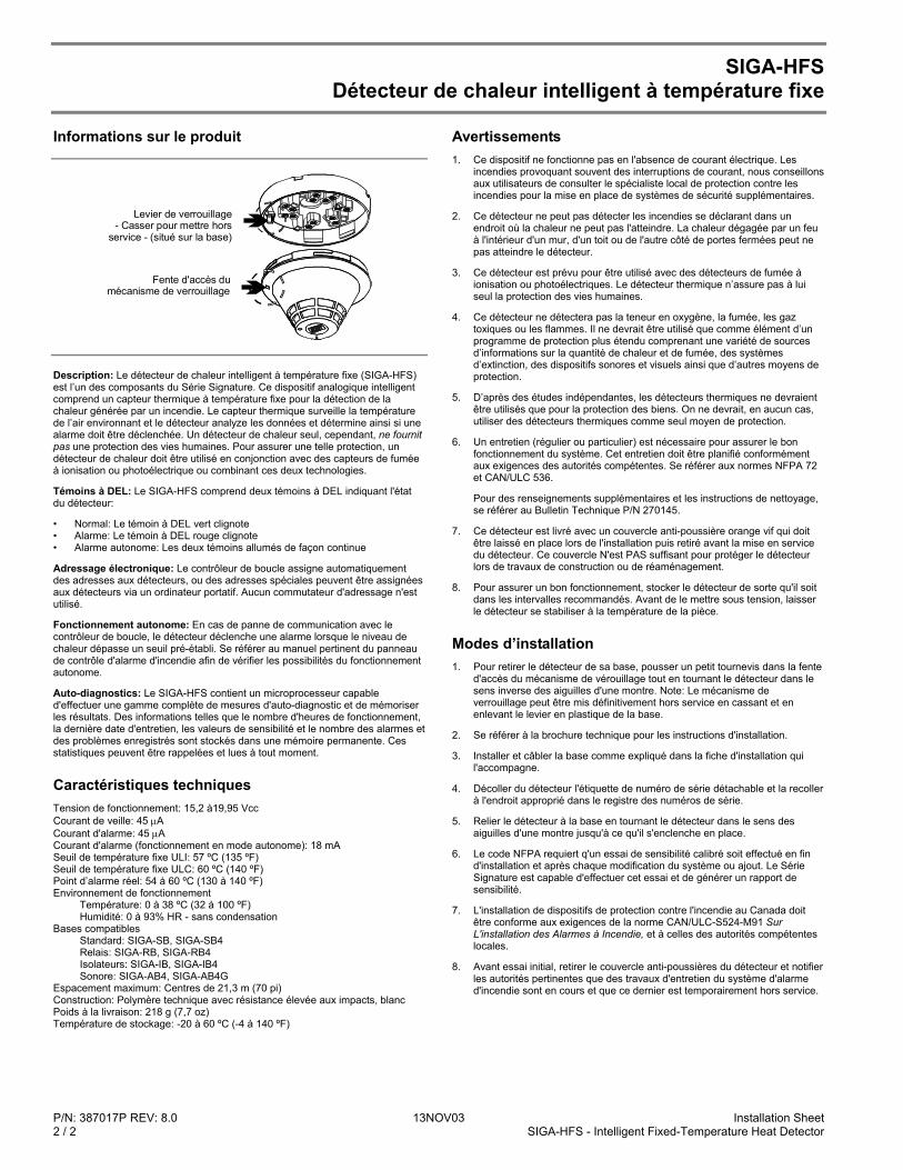
P/N: 387017P REV: 8.0 13NOV03 Installation Sheet 2 / 2 SIGA-HFS - Intelligent Fixed-Temperature Heat Detector
SIGA-HFS Détecteur de chaleur intelligent à température fixe
Informations sur le produit
Levier de verrouillage- Casser pour mettre hors
service - (situé sur la base)
Fente d'accès du mécanisme de verrouillage
Description: Le détecteur de chaleur intelligent à température fixe (SIGA-HFS) est l’un des composants du Série Signature. Ce dispositif analogique intelligent comprend un capteur thermique à température fixe pour la détection de la chaleur générée par un incendie. Le capteur thermique surveille la température de l’air environnant et le détecteur analyze les données et détermine ainsi si une alarme doit être déclenchée. Un détecteur de chaleur seul, cependant, ne fournit pas une protection des vies humaines. Pour assurer une telle protection, un détecteur de chaleur doit être utilisé en conjonction avec des capteurs de fumée à ionisation ou photoélectrique ou combinant ces deux technologies.
Témoins à DEL: Le SIGA-HFS comprend deux témoins à DEL indiquant l'état du détecteur:
• Normal: Le témoin à DEL vert clignote • Alarme: Le témoin à DEL rouge clignote • Alarme autonome: Les deux témoins allumés de façon continue
Adressage électronique: Le contrôleur de boucle assigne automatiquement des adresses aux détecteurs, ou des adresses spéciales peuvent être assignées aux détecteurs via un ordinateur portatif. Aucun commutateur d'adressage n'est utilisé.
Fonctionnement autonome: En cas de panne de communication avec le contrôleur de boucle, le détecteur déclenche une alarme lorsque le niveau de chaleur dépasse un seuil pré-établi. Se référer au manuel pertinent du panneau de contrôle d'alarme d'incendie afin de vérifier les possibilités du fonctionnement autonome.
Auto-diagnostics: Le SIGA-HFS contient un microprocesseur capable d'effectuer une gamme complète de mesures d'auto-diagnostic et de mémoriser les résultats. Des informations telles que le nombre d'heures de fonctionnement, la dernière date d'entretien, les valeurs de sensibilité et le nombre des alarmes et des problèmes enregistrés sont stockés dans une mémoire permanente. Ces statistiques peuvent être rappelées et lues à tout moment.
Caractéristiques techniques Tension de fonctionnement: 15,2 à19,95 Vcc Courant de veille: 45 µA Courant d'alarme: 45 µA Courant d'alarme (fonctionnement en mode autonome): 18 mA Seuil de température fixe ULI: 57 ºC (135 ºF) Seuil de température fixe ULC: 60 ºC (140 ºF) Point d’alarme réel: 54 à 60 ºC (130 à 140 ºF) Environnement de fonctionnement
Température: 0 à 38 ºC (32 à 100 ºF) Humidité: 0 à 93% HR - sans condensation
Bases compatibles Standard: SIGA-SB, SIGA-SB4 Relais: SIGA-RB, SIGA-RB4 Isolateurs: SIGA-IB, SIGA-IB4 Sonore: SIGA-AB4, SIGA-AB4G
Espacement maximum: Centres de 21,3 m (70 pi) Construction: Polymère technique avec résistance élevée aux impacts, blanc Poids à la livraison: 218 g (7,7 oz) Température de stockage: -20 à 60 ºC (-4 à 140 ºF)
Avertissements 1. Ce dispositif ne fonctionne pas en l'absence de courant électrique. Les
incendies provoquant souvent des interruptions de courant, nous conseillons aux utilisateurs de consulter le spécialiste local de protection contre les incendies pour la mise en place de systèmes de sécurité supplémentaires.
2. Ce détecteur ne peut pas détecter les incendies se déclarant dans un endroit où la chaleur ne peut pas l'atteindre. La chaleur dégagée par un feu à l'intérieur d'un mur, d'un toit ou de l'autre côté de portes fermées peut ne pas atteindre le détecteur.
3. Ce détecteur est prévu pour être utilisé avec des détecteurs de fumée à ionisation ou photoélectriques. Le détecteur thermique n’assure pas à lui seul la protection des vies humaines.
4. Ce détecteur ne détectera pas la teneur en oxygène, la fumée, les gaz toxiques ou les flammes. Il ne devrait être utilisé que comme élément d’un programme de protection plus étendu comprenant une variété de sources d’informations sur la quantité de chaleur et de fumée, des systèmes d’extinction, des dispositifs sonores et visuels ainsi que d’autres moyens de protection.
5. D’après des études indépendantes, les détecteurs thermiques ne devraient être utilisés que pour la protection des biens. On ne devrait, en aucun cas, utiliser des détecteurs thermiques comme seul moyen de protection.
6. Un entretien (régulier ou particulier) est nécessaire pour assurer le bon fonctionnement du système. Cet entretien doit être planifié conformément aux exigences des autorités compétentes. Se référer aux normes NFPA 72 et CAN/ULC 536.
Pour des renseignements supplémentaires et les instructions de nettoyage, se référer au Bulletin Technique P/N 270145.
7. Ce détecteur est livré avec un couvercle anti-poussière orange vif qui doit être laissé en place lors de l'installation puis retiré avant la mise en service du détecteur. Ce couvercle N'est PAS suffisant pour protéger le détecteur lors de travaux de construction ou de réaménagement.
8. Pour assurer un bon fonctionnement, stocker le détecteur de sorte qu'il soit dans les intervalles recommandés. Avant de le mettre sous tension, laisser le détecteur se stabiliser à la température de la pièce.
Modes d’installation 1. Pour retirer le détecteur de sa base, pousser un petit tournevis dans la fente
d'accès du mécanisme de vérouillage tout en tournant le détecteur dans le sens inverse des aiguilles d'une montre. Note: Le mécanisme de verrouillage peut être mis définitivement hors service en cassant et en enlevant le levier en plastique de la base.
2. Se référer à la brochure technique pour les instructions d'installation.
3. Installer et câbler la base comme expliqué dans la fiche d'installation qui l'accompagne.
4. Décoller du détecteur l'étiquette de numéro de série détachable et la recoller à l'endroit approprié dans le registre des numéros de série.
5. Relier le détecteur à la base en tournant le détecteur dans le sens des aiguilles d'une montre jusqu'à ce qu'il s'enclenche en place.
6. Le code NFPA requiert q'un essai de sensibilité calibré soit effectué en fin d'installation et après chaque modification du système ou ajout. Le Série Signature est capable d'effectuer cet essai et de générer un rapport de sensibilité.
7. L'installation de dispositifs de protection contre l'incendie au Canada doit être conforme aux exigences de la norme CAN/ULC-S524-M91 Sur L'installation des Alarmes à Incendie, et à celles des autorités compétentes locales.
8. Avant essai initial, retirer le couvercle anti-poussières du détecteur et notifier les autorités pertinentes que des travaux d'entretien du système d'alarme d'incendie sont en cours et que ce dernier est temporairement hors service.
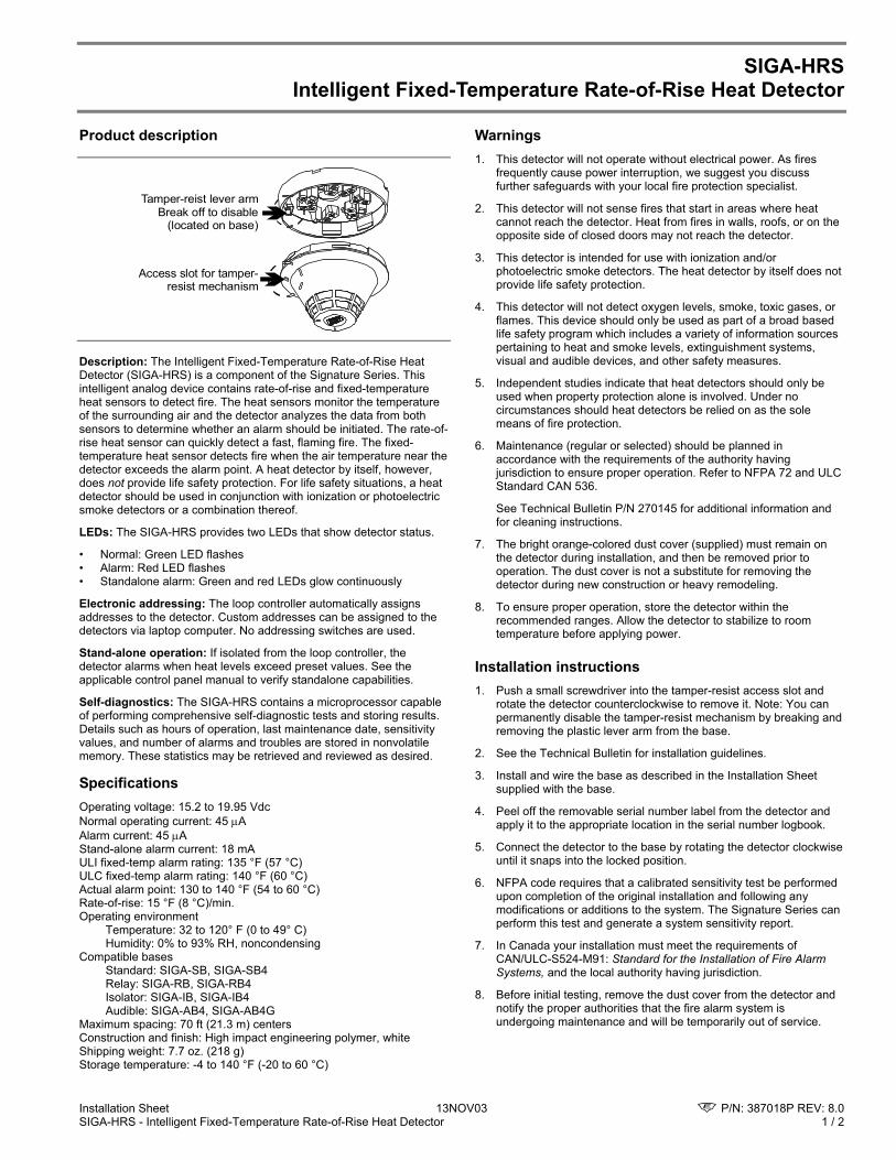
Installation Sheet 13NOV03 P/N: 387018P REV: 8.0 SIGA-HRS - Intelligent Fixed-Temperature Rate-of-Rise Heat Detector 1 / 2
SIGA-HRS Intelligent Fixed-Temperature Rate-of-Rise Heat Detector
Product description
Tamper-reist lever armBreak off to disable
(located on base)
Access slot for tamper-resist mechanism
Description: The Intelligent Fixed-Temperature Rate-of-Rise Heat Detector (SIGA-HRS) is a component of the Signature Series. This intelligent analog device contains rate-of-rise and fixed-temperature heat sensors to detect fire. The heat sensors monitor the temperature of the surrounding air and the detector analyzes the data from both sensors to determine whether an alarm should be initiated. The rate-of-rise heat sensor can quickly detect a fast, flaming fire. The fixed-temperature heat sensor detects fire when the air temperature near the detector exceeds the alarm point. A heat detector by itself, however, does not provide life safety protection. For life safety situations, a heat detector should be used in conjunction with ionization or photoelectric smoke detectors or a combination thereof.
LEDs: The SIGA-HRS provides two LEDs that show detector status.
• Normal: Green LED flashes • Alarm: Red LED flashes • Standalone alarm: Green and red LEDs glow continuously
Electronic addressing: The loop controller automatically assigns addresses to the detector. Custom addresses can be assigned to the detectors via laptop computer. No addressing switches are used.
Stand-alone operation: If isolated from the loop controller, the detector alarms when heat levels exceed preset values. See the applicable control panel manual to verify standalone capabilities.
Self-diagnostics: The SIGA-HRS contains a microprocessor capable of performing comprehensive self-diagnostic tests and storing results. Details such as hours of operation, last maintenance date, sensitivity values, and number of alarms and troubles are stored in nonvolatile memory. These statistics may be retrieved and reviewed as desired.
Specifications Operating voltage: 15.2 to 19.95 Vdc Normal operating current: 45 µA Alarm current: 45 µA Stand-alone alarm current: 18 mA ULI fixed-temp alarm rating: 135 °F (57 °C) ULC fixed-temp alarm rating: 140 °F (60 °C) Actual alarm point: 130 to 140 °F (54 to 60 °C) Rate-of-rise: 15 °F (8 °C)/min. Operating environment
Temperature: 32 to 120° F (0 to 49° C) Humidity: 0% to 93% RH, noncondensing
Compatible bases Standard: SIGA-SB, SIGA-SB4 Relay: SIGA-RB, SIGA-RB4 Isolator: SIGA-IB, SIGA-IB4 Audible: SIGA-AB4, SIGA-AB4G
Maximum spacing: 70 ft (21.3 m) centers Construction and finish: High impact engineering polymer, white Shipping weight: 7.7 oz. (218 g) Storage temperature: -4 to 140 °F (-20 to 60 °C)
Warnings 1. This detector will not operate without electrical power. As fires
frequently cause power interruption, we suggest you discuss further safeguards with your local fire protection specialist.
2. This detector will not sense fires that start in areas where heat cannot reach the detector. Heat from fires in walls, roofs, or on the opposite side of closed doors may not reach the detector.
3. This detector is intended for use with ionization and/or photoelectric smoke detectors. The heat detector by itself does not provide life safety protection.
4. This detector will not detect oxygen levels, smoke, toxic gases, or flames. This device should only be used as part of a broad based life safety program which includes a variety of information sources pertaining to heat and smoke levels, extinguishment systems, visual and audible devices, and other safety measures.
5. Independent studies indicate that heat detectors should only be used when property protection alone is involved. Under no circumstances should heat detectors be relied on as the sole means of fire protection.
6. Maintenance (regular or selected) should be planned in accordance with the requirements of the authority having jurisdiction to ensure proper operation. Refer to NFPA 72 and ULC Standard CAN 536.
See Technical Bulletin P/N 270145 for additional information and for cleaning instructions.
7. The bright orange-colored dust cover (supplied) must remain on the detector during installation, and then be removed prior to operation. The dust cover is not a substitute for removing the detector during new construction or heavy remodeling.
8. To ensure proper operation, store the detector within the recommended ranges. Allow the detector to stabilize to room temperature before applying power.
Installation instructions 1. Push a small screwdriver into the tamper-resist access slot and
rotate the detector counterclockwise to remove it. Note: You can permanently disable the tamper-resist mechanism by breaking and removing the plastic lever arm from the base.
2. See the Technical Bulletin for installation guidelines.
3. Install and wire the base as described in the Installation Sheet supplied with the base.
4. Peel off the removable serial number label from the detector and apply it to the appropriate location in the serial number logbook.
5. Connect the detector to the base by rotating the detector clockwise until it snaps into the locked position.
6. NFPA code requires that a calibrated sensitivity test be performed upon completion of the original installation and following any modifications or additions to the system. The Signature Series can perform this test and generate a system sensitivity report.
7. In Canada your installation must meet the requirements of CAN/ULC-S524-M91: Standard for the Installation of Fire Alarm Systems, and the local authority having jurisdiction.
8. Before initial testing, remove the dust cover from the detector and notify the proper authorities that the fire alarm system is undergoing maintenance and will be temporarily out of service.
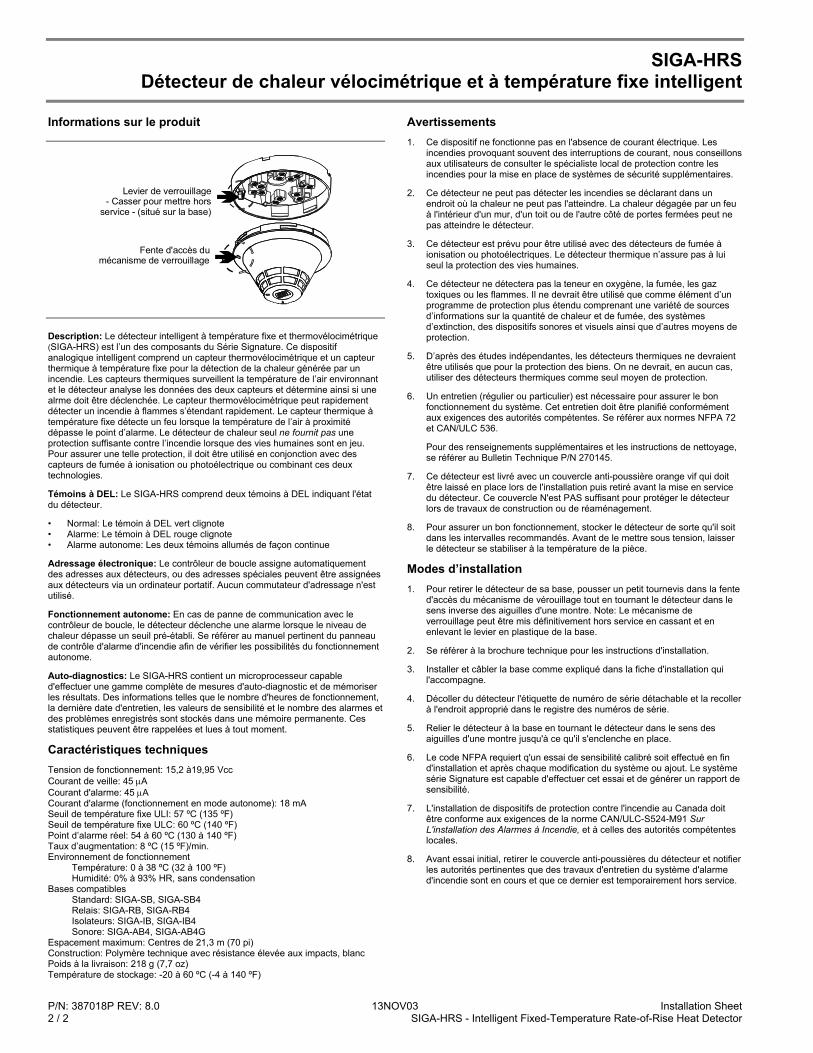
P/N: 387018P REV: 8.0 13NOV03 Installation Sheet 2 / 2 SIGA-HRS - Intelligent Fixed-Temperature Rate-of-Rise Heat Detector
SIGA-HRS Détecteur de chaleur vélocimétrique et à température fixe intelligent
Informations sur le produit
Levier de verrouillage- Casser pour mettre hors
service - (situé sur la base)
Fente d'accès du mécanisme de verrouillage
Description: Le détecteur intelligent à température fixe et thermovélocimétrique (SIGA-HRS) est l’un des composants du Série Signature. Ce dispositif analogique intelligent comprend un capteur thermovélocimétrique et un capteur thermique à température fixe pour la détection de la chaleur générée par un incendie. Les capteurs thermiques surveillent la température de l’air environnant et le détecteur analyse les données des deux capteurs et détermine ainsi si une alrme doit être déclenchée. Le capteur thermovélocimétrique peut rapidement détecter un incendie à flammes s’étendant rapidement. Le capteur thermique à température fixe détecte un feu lorsque la température de l’air à proximité dépasse le point d’alarme. Le détecteur de chaleur seul ne fournit pas une protection suffisante contre l’incendie lorsque des vies humaines sont en jeu. Pour assurer une telle protection, il doit être utilisé en conjonction avec des capteurs de fumée à ionisation ou photoélectrique ou combinant ces deux technologies.
Témoins à DEL: Le SIGA-HRS comprend deux témoins à DEL indiquant l'état du détecteur.
• Normal: Le témoin à DEL vert clignote • Alarme: Le témoin à DEL rouge clignote • Alarme autonome: Les deux témoins allumés de façon continue
Adressage électronique: Le contrôleur de boucle assigne automatiquement des adresses aux détecteurs, ou des adresses spéciales peuvent être assignées aux détecteurs via un ordinateur portatif. Aucun commutateur d'adressage n'est utilisé.
Fonctionnement autonome: En cas de panne de communication avec le contrôleur de boucle, le détecteur déclenche une alarme lorsque le niveau de chaleur dépasse un seuil pré-établi. Se référer au manuel pertinent du panneau de contrôle d'alarme d'incendie afin de vérifier les possibilités du fonctionnement autonome.
Auto-diagnostics: Le SIGA-HRS contient un microprocesseur capable d'effectuer une gamme complète de mesures d'auto-diagnostic et de mémoriser les résultats. Des informations telles que le nombre d'heures de fonctionnement, la dernière date d'entretien, les valeurs de sensibilité et le nombre des alarmes et des problèmes enregistrés sont stockés dans une mémoire permanente. Ces statistiques peuvent être rappelées et lues à tout moment.
Caractéristiques techniques Tension de fonctionnement: 15,2 à19,95 Vcc Courant de veille: 45 µA Courant d'alarme: 45 µA Courant d'alarme (fonctionnement en mode autonome): 18 mA Seuil de température fixe ULI: 57 ºC (135 ºF) Seuil de température fixe ULC: 60 ºC (140 ºF) Point d’alarme réel: 54 à 60 ºC (130 à 140 ºF) Taux d’augmentation: 8 ºC (15 ºF)/min. Environnement de fonctionnement
Température: 0 à 38 ºC (32 à 100 ºF) Humidité: 0% à 93% HR, sans condensation
Bases compatibles Standard: SIGA-SB, SIGA-SB4 Relais: SIGA-RB, SIGA-RB4 Isolateurs: SIGA-IB, SIGA-IB4 Sonore: SIGA-AB4, SIGA-AB4G
Espacement maximum: Centres de 21,3 m (70 pi) Construction: Polymère technique avec résistance élevée aux impacts, blanc Poids à la livraison: 218 g (7,7 oz) Température de stockage: -20 à 60 ºC (-4 à 140 ºF)
Avertissements 1. Ce dispositif ne fonctionne pas en l'absence de courant électrique. Les
incendies provoquant souvent des interruptions de courant, nous conseillons aux utilisateurs de consulter le spécialiste local de protection contre les incendies pour la mise en place de systèmes de sécurité supplémentaires.
2. Ce détecteur ne peut pas détecter les incendies se déclarant dans un endroit où la chaleur ne peut pas l'atteindre. La chaleur dégagée par un feu à l'intérieur d'un mur, d'un toit ou de l'autre côté de portes fermées peut ne pas atteindre le détecteur.
3. Ce détecteur est prévu pour être utilisé avec des détecteurs de fumée à ionisation ou photoélectriques. Le détecteur thermique n’assure pas à lui seul la protection des vies humaines.
4. Ce détecteur ne détectera pas la teneur en oxygène, la fumée, les gaz toxiques ou les flammes. Il ne devrait être utilisé que comme élément d’un programme de protection plus étendu comprenant une variété de sources d’informations sur la quantité de chaleur et de fumée, des systèmes d’extinction, des dispositifs sonores et visuels ainsi que d’autres moyens de protection.
5. D’après des études indépendantes, les détecteurs thermiques ne devraient être utilisés que pour la protection des biens. On ne devrait, en aucun cas, utiliser des détecteurs thermiques comme seul moyen de protection.
6. Un entretien (régulier ou particulier) est nécessaire pour assurer le bon fonctionnement du système. Cet entretien doit être planifié conformément aux exigences des autorités compétentes. Se référer aux normes NFPA 72 et CAN/ULC 536.
Pour des renseignements supplémentaires et les instructions de nettoyage, se référer au Bulletin Technique P/N 270145.
7. Ce détecteur est livré avec un couvercle anti-poussière orange vif qui doit être laissé en place lors de l'installation puis retiré avant la mise en service du détecteur. Ce couvercle N'est PAS suffisant pour protéger le détecteur lors de travaux de construction ou de réaménagement.
8. Pour assurer un bon fonctionnement, stocker le détecteur de sorte qu'il soit dans les intervalles recommandés. Avant de le mettre sous tension, laisser le détecteur se stabiliser à la température de la pièce.
Modes d’installation 1. Pour retirer le détecteur de sa base, pousser un petit tournevis dans la fente
d'accès du mécanisme de vérouillage tout en tournant le détecteur dans le sens inverse des aiguilles d'une montre. Note: Le mécanisme de verrouillage peut être mis définitivement hors service en cassant et en enlevant le levier en plastique de la base.
2. Se référer à la brochure technique pour les instructions d'installation.
3. Installer et câbler la base comme expliqué dans la fiche d'installation qui l'accompagne.
4. Décoller du détecteur l'étiquette de numéro de série détachable et la recoller à l'endroit approprié dans le registre des numéros de série.
5. Relier le détecteur à la base en tournant le détecteur dans le sens des aiguilles d'une montre jusqu'à ce qu'il s'enclenche en place.
6. Le code NFPA requiert q'un essai de sensibilité calibré soit effectué en fin d'installation et après chaque modification du système ou ajout. Le système série Signature est capable d'effectuer cet essai et de générer un rapport de sensibilité.
7. L'installation de dispositifs de protection contre l'incendie au Canada doit être conforme aux exigences de la norme CAN/ULC-S524-M91 Sur L'installation des Alarmes à Incendie, et à celles des autorités compétentes locales.
8. Avant essai initial, retirer le couvercle anti-poussières du détecteur et notifier les autorités pertinentes que des travaux d'entretien du système d'alarme d'incendie sont en cours et que ce dernier est temporairement hors service.
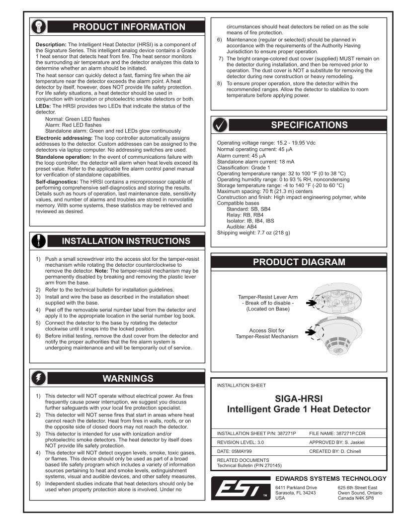
INSTALLATION INSTRUCTIONS
PRODUCT INFORMATION
INSTALLATION SHEET
DATE: 05MAY99
INSTALLATION SHEET P/N: 387271P FILE NAME: .CDR387271P
REVISION LEVEL: 3.0
CREATED BY: D. Chinell
APPROVED BY: S. Jaskiel
WARNINGS
Operating voltage range: 15.2 - 19.95 VdcNormal operating current: 45 AAlarm current: 45 AStandalone alarm current: 18 mAClassification: Grade 1Operating temperature range: 32 to 100 °F (0 to 38 °C)Operating humidity range: 0 to 93 % RH, noncondensingStorage temperature range: -4 to 140 °F (-20 to 60 °C)Maximum spacing: 70 ft (21.3 m) centersConstruction and finish: High impact engineering polymer, whiteCompatible bases
Standard: SB, SB4Relay: RB, RB4Isolator: IB, IB4, IBSAudible: AB4
Shipping weight: 7.7 oz (218 g)
SPECIFICATIONS
RELATED DOCUMENTSTechnical Bulletin (P/N 270145)
Description:
LEDs:
Electronic addressing:
Standalone operation:
Self-diagnostics:
The Intelligent Heat Detector (HRSI) is a component ofthe Signature Series. This intelligent analog device contains a Grade1 heat sensor that detects heat from fire. The heat sensor monitorsthe surrounding air temperature and the detector analyzes this data todetermine whether an alarm should be initiated.The heat sensor can quickly detect a fast, flaming fire when the airtemperature near the detector exceeds the alarm point. A heatdetector by itself, however, does NOT provide life safety protection.For life safety situations, a heat detector should be used inconjunction with ionization or photoelectric smoke detectors or both.
The HRSI provides two LEDs that indicate the status of thedetector.
Normal: Green LED flashesAlarm: Red LED flashesStandalone alarm: Green and red LEDs glow continuously
The loop controller automatically assignsaddresses to the detector. Custom addresses can be assigned to thedetectors via laptop computer. No addressing switches are used.
In the event of communications failure withthe loop controller, the detector will alarm when heat levels exceed itspreset value. Refer to the applicable fire alarm control panel manualfor verification of standalone capabilities.
The HRSI contains a microprocessor capable ofperforming comprehensive self-diagnostics and storing the results.Details such as hours of operation, last maintenance date, sensitivityvalues, and number of alarms and troubles are stored in nonvolatilememory. With some systems, these statistics may be retrieved andreviewed as desired.
1) Push a small screwdriver into the access slot for the tamper-resistmechanism while rotating the detector counterclockwise toremove the detector. The tamper-resist mechanism may bepermanently disabled by breaking and removing the plastic leverarm from the base.
2) Refer to the technical bulletin for installation guidelines.3) Install and wire the base as described in the installation sheet
supplied with the base.4) Peel off the removable serial number label from the detector and
apply it to the appropriate location in the serial number log book.5) Connect the detector to the base by rotating the detector
clockwise until it snaps into the locked position.6) Before initial testing, remove the dust cover from the detector and
notify the proper authorities that the fire alarm system isundergoing maintenance and will be temporarily out of service.
Note:
1) This detector will NOT operate without electrical power. As firesfrequently cause power interruption, we suggest you discussfurther safeguards with your local fire protection specialist.
2) This detector will NOT sense fires that start in areas where heatcannot reach the detector. Heat from fires in walls, roofs, or onthe opposite side of closed doors may not reach the detector.
3) This detector is intended for use with ionization and/orphotoelectric smoke detectors. The heat detector by itself doesNOT provide life safety protection.
4) This detector will NOT detect oxygen levels, smoke, toxic gases,or flames. This device should only be used as part of a broadbased life safety program which includes a variety of informationsources pertaining to heat and smoke levels, extinguishmentsystems, visual and audible devices, and other safety measures.
5) Independent studies indicate that heat detectors should only beused when property protection alone is involved. Under no
circumstances should heat detectors be relied on as the solemeans of fire protection.
6) Maintenance (regular or selected) should be planned inaccordance with the requirements of the Authority HavingJurisdiction to ensure proper operation.
7) The bright orange-colored dust cover (supplied) MUST remain onthe detector during installation, and then be removed prior tooperation. The dust cover is NOT a substitute for removing thedetector during new construction or heavy remodeling.
8) To ensure proper operation, store the detector within therecommended ranges. Allow the detector to stabilize to roomtemperature before applying power.
PRODUCT DIAGRAM
Tamper-Resist Lever Arm- Break off to disable -
(Located on Base)
Access Slot forTamper-Resist Mechanism
SIGA-HRSIIntelligent Grade 1 Heat Detector
EDWARDS SYSTEMS TECHNOLOGY
6411 Parkland DriveSarasota, FL 34243USA
625 6th Street EastOwen Sound, OntarioCanada N4K 5P8
TM

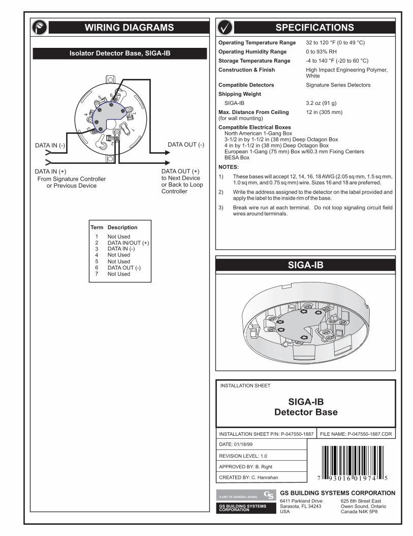
SPECIFICATIONS
SIGA-IB
WIRING DIAGRAMS
Operating Temperature Range
Operating Humidity Range
Storage Temperature Range
Construction & Finish
Compatible Detectors
Shipping Weight
Max. Distance From Ceiling
Compatible Electrical Boxes
NOTES:
32 to 120 °F (0 to 49 °C)
0 to 93% RH
-4 to 140 °F (-20 to 60 °C)
High Impact Engineering Polymer,White
Signature Series Detectors
SIGA-IB 3.2 oz (91 g)
12 in (305 mm)(for wall mounting)
North American 1-Gang Box3-1/2 in by 1-1/2 in (38 mm) Deep Octagon Box4 in by 1-1/2 in (38 mm) Deep Octagon BoxEuropean 1-Gang (75 mm) Box w/60.3 mm Fixing CentersBESA Box
1)
2) Write the address assigned to the detector on the label provided andapply the label to the inside rim of the base.
3) Break wire run at each terminal. Do not loop signaling circuit fieldwires around terminals.
These bases will accept 12, 14, 16, 18AWG (2.05 sq mm, 1.5 sq mm,1.0 sq mm, and 0.75 sq mm) wire. Sizes 16 and 18 are preferred.
Term
1 Not Used
45
DATA IN (-)
Not Used
7 Not Used
2 DATA IN/OUT (+)3
Not Used
6 DATA OUT (-)
Description
Isolator Detector Base, SIGA-IB
INSTALLATION SHEET
INSTALLATION SHEET P/N: P-047550-1887
REVISION LEVEL: 1.0
FILE NAME: P-047550-1887.CDR
SIGA-IBDetector Base
DATE: 01/18/99
CREATED BY: C. Hanrahan
APPROVED BY: B. Right
GS BUILDING SYSTEMSCORPORATION
A UNIT OF GENERAL SIGNALGS BUILDING SYSTEMS CORPORATION6411 Parkland DriveSarasota, FL 34243USA
625 6th Street EastOwen Sound, OntarioCanada N4K 5P8
7 59 3 0 1 6 0 1 9 7 4
56
34
17
2
DATA OUT (-)
DATA OUT (+)to Next Deviceor Back to LoopController
From Signature Controlleror Previous Device
DATA IN (-)
DATA IN (+)
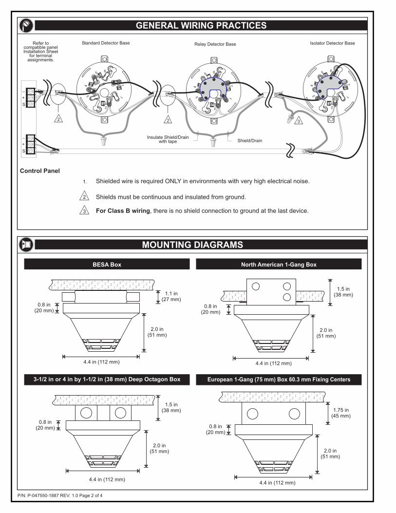
P/N: P-047550-1887 REV: 1.0 Page 2 of 4
GENERAL WIRING PRACTICES
MOUNTING DIAGRAMS
1.1 in(27 mm)
2.0 in(51 mm)
4.4 in (112 mm)
0.8 in(20 mm)
4.4 in (112 mm)
1.5 in(38 mm)
2.0 in(51 mm)
0.8 in(20 mm)
BESA Box North American 1-Gang Box
4.4 in (112 mm)
1.5 in(38 mm)
2.0 in(51 mm)
0.8 in(20 mm)
4.4 in (112 mm)
1.75 in(45 mm)
2.0 in(51 mm)
0.8 in(20 mm)
3-1/2 in or 4 in by 1-1/2 in (38 mm) Deep Octagon Box European 1-Gang (75 mm) Box 60.3 mm Fixing Centers
For Class B wiring, there is no shield connection to ground at the last device.
Control Panel
3
1.
2
Standard Detector Base
2
Relay Detector Base
Insulate Shield/Drainwith tape Shield/Drain
2
56
34
17
2
Isolator Detector Base
3
56
34
17
2
56
34
17
2
Shields must be continuous and insulated from ground.
Shielded wire is required ONLY in environments with very high electrical noise.
+
_
S
+
_
S
Refer tocompatible panelInstallation Sheet
for terminalassignments.
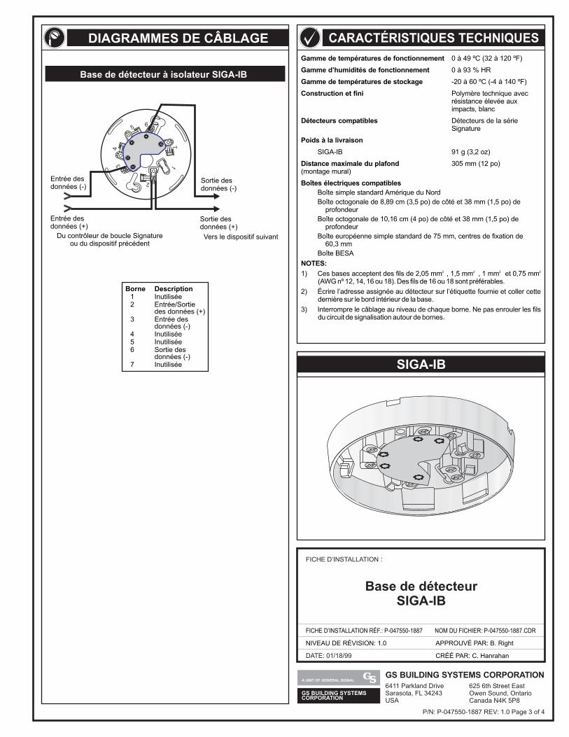
GS BUILDING SYSTEMSCORPORATION
A UNIT OF GENERAL SIGNALGS BUILDING SYSTEMS CORPORATION6411 Parkland DriveSarasota, FL 34243USA
625 6th Street EastOwen Sound, OntarioCanada N4K 5P8
DATE: 01/18/99
FICHE D’INSTALLATION :
FICHE D’INSTALLATION RÉF.: P-047550-1887
NIVEAU DE RÉVISION: 1.0
NOM DU FICHIER: P-047550-1887.CDR
CRÉÉ PAR: C. Hanrahan
APPROUVÉ PAR: B. Right
Base de détecteurSIGA-IB
SIGA-IB
Gamme de températures de fonctionnement
Gamme d’humidités de fonctionnement
Gamme de températures de stockage
Construction et fini
Détecteurs compatibles
Poids à la livraison
Distance maximale du plafond
Boîtes électriques compatibles
NOTES:
0 à 49 ºC (32 à 120 ºF)
0 à 93 % HR
-20 à 60 ºC (-4 à 140 ºF)
Polymère technique avecrésistance élevée auximpacts, blanc
Détecteurs de la sérieSignature
SIGA-IB 91 g (3,2 oz)
305 mm (12 po)(montage mural)
Boîte simple standard Amérique du NordBoîte octogonale de 8,89 cm (3,5 po) de côté et 38 mm (1,5 po) de
profondeurBoîte octogonale de 10,16 cm (4 po) de côté et 38 mm (1,5 po) de
profondeurBoîte européenne simple standard de 75 mm, centres de fixation de
60,3 mmBoîte BESA
1) Ces bases acceptent des fils de 2,05 mm , 1,5 mm , 1 mm et 0,75 mm(AWG nº 12, 14, 16 ou 18). Des fils de 16 ou 18 sont préférables.
2) Écrire l’adresse assignée au détecteur sur l’étiquette fournie et coller cettedernière sur le bord intérieur de la base.
3) Interrompre le câblage au niveau de chaque borne. Ne pas enrouler les filsdu circuit de signalisation autour de bornes.
2 2 2 2
DIAGRAMMES DE CÂBLAGE CARACTÉRISTIQUES TECHNIQUES
P/N: P-047550-1887 REV: 1.0 Page 3 of 4
Base de détecteur à isolateur SIGA-IB
56
34
17
2
Entrée desdonnées (+)
Du contrôleur de boucle Signatureou du dispositif précédent
Entrée desdonnées (-)
Vers le dispositif suivant
Sortie desdonnées (-)
Sortie desdonnées (+)
1 Inutilisée2 Entrée/Sortie
des données (+)3 Entrée des
données (-)4 Inutilisée5 Inutilisée6 Sortie des
données (-)7 Inutilisée
Borne Description
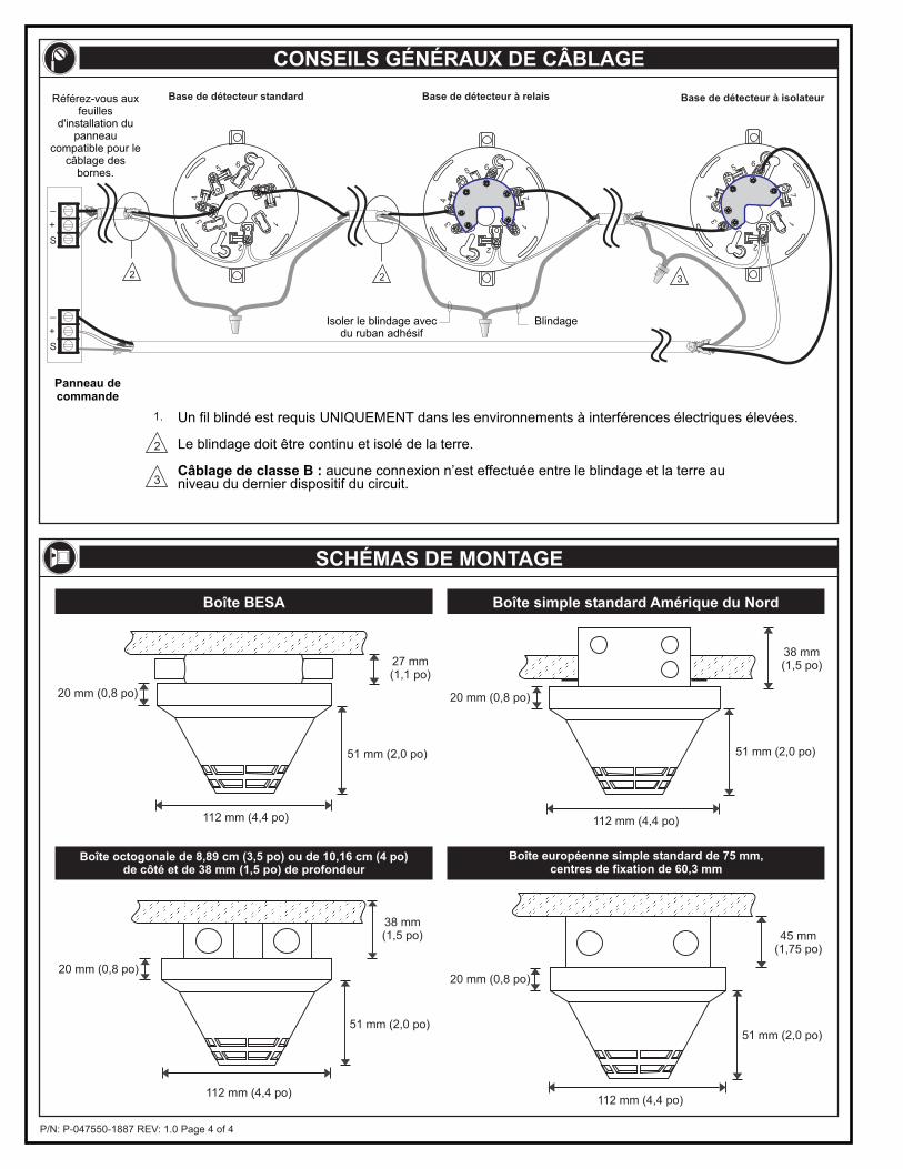
P/N: P-047550-1887 REV: 1.0 Page 4 of 4
27 mm(1,1 po)
51 mm (2,0 po)
112 mm (4,4 po)
20 mm (0,8 po)
112 mm (4,4 po)
38 mm(1,5 po)
51 mm (2,0 po)
20 mm (0,8 po)
112 mm (4,4 po)
38 mm(1,5 po)
51 mm (2,0 po)
20 mm (0,8 po)
112 mm (4,4 po)
45 mm(1,75 po)
51 mm (2,0 po)
20 mm (0,8 po)
Boîte BESA
Boîte octogonale de 8,89 cm (3,5 po) ou de 10,16 cm (4 po)de côté et de 38 mm (1,5 po) de profondeur
Boîte européenne simple standard de 75 mm,centres de fixation de 60,3 mm
CONSEILS GÉNÉRAUX DE CÂBLAGE
SCHÉMAS DE MONTAGE
Boîte simple standard Amérique du Nord
Un fil blindé est requis UNIQUEMENT dans les environnements à interférences électriques élevées.
Le blindage doit être continu et isolé de la terre.
aucune connexion n’est effectuée entre le blindage et la terre auniveau du dernier dispositif du circuit.Câblage de classe B :
Panneau decommande
Isoler le blindage avecdu ruban adhésif
Blindage
3
1.
2
2 2
56
34
17
2
3
56
34
17
2
56
34
17
2
Base de détecteur standard Base de détecteur à relais Base de détecteur à isolateur
+
_
S
+
_
S
Référez-vous auxfeuilles
d'installation dupanneau
compatible pour lecâblage des
bornes.
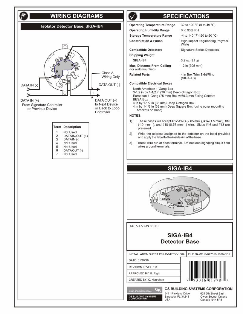
Operating Temperature Range 32 to 120 °F (0 to 49 °C)
Operating Humidity Range 0 to 93% RH
Storage Temperature Range -4 to 140 °F (-20 to 60 °C)
Construction & Finish High Impact Engineering Polymer, White
Compatible Detectors Signature Series Detectors
Shipping Weight
SIGA-IB4 3.2 oz (91 g)
Max. Distance From Ceiling 12 in (305 mm)(for wall mounting)
Related Parts 4 in Box Trim Skirt/Ring(SIGA-TS)
Compatible Electrical Boxes
North American 1-Gang Box3-1/2 in by 1-1/2 in (38 mm) Deep Octagon BoxEuropean 1-Gang (75 mm) Box w/60.3 mm Fixing CentersBESA Box4 in by 1-1/2 in (38 mm) Deep Octagon Box4 in by 1-1/2 in (38 mm) Deep Square Box (using outer mounting
brackets on base)
NOTES:
2 2 1) These bases will accept # 12 AWG (2.05 mm ), #14 (1.5 mm ), #16 2 2 (1.0 mm ), and #18 (0.75 mm ) wire. Sizes #16 and #18 are
preferred.
2) Write the address assigned to the detector on the label provided and apply the label to the inside rim of the base.
3) Break wire run at each terminal. Do not loop signaling circuit field wires around terminals.
SIGA-IB4
Term
1 Not Used
45
DATA IN (-)
Not Used
7 Not Used
2 DATA IN/OUT (+)3
Not Used
6 DATA OUT (-)
Description
56
34
17
2
DATA OUT (-)
Class A Wiring Only
DATA OUT (+)to Next Deviceor Back to Loop Controller
From Signature Controlleror Previous Device
DATA IN (-)
DATA IN (+)
Isolator Detector Base, SIGA-IB4
SPECIFICATIONSWIRING DIAGRAMS
INSTALLATION SHEET
INSTALLATION SHEET P/N: P-047550-1889
REVISION LEVEL: 1.0
FILE NAME: P-047550-1889.CDR
SIGA-IB4Detector Base
DATE: 01/18/99
CREATED BY: C. Hanrahan
APPROVED BY: B. Right
GS BUILDING SYSTEMSCORPORATION
A UNIT OF GENERAL SIGNALGS BUILDING SYSTEMS CORPORATION6411 Parkland DriveSarasota, FL 34243USA
625 6th Street EastOwen Sound, OntarioCanada N4K 5P8
7 39 3 0 1 6 0 1 9 7 8
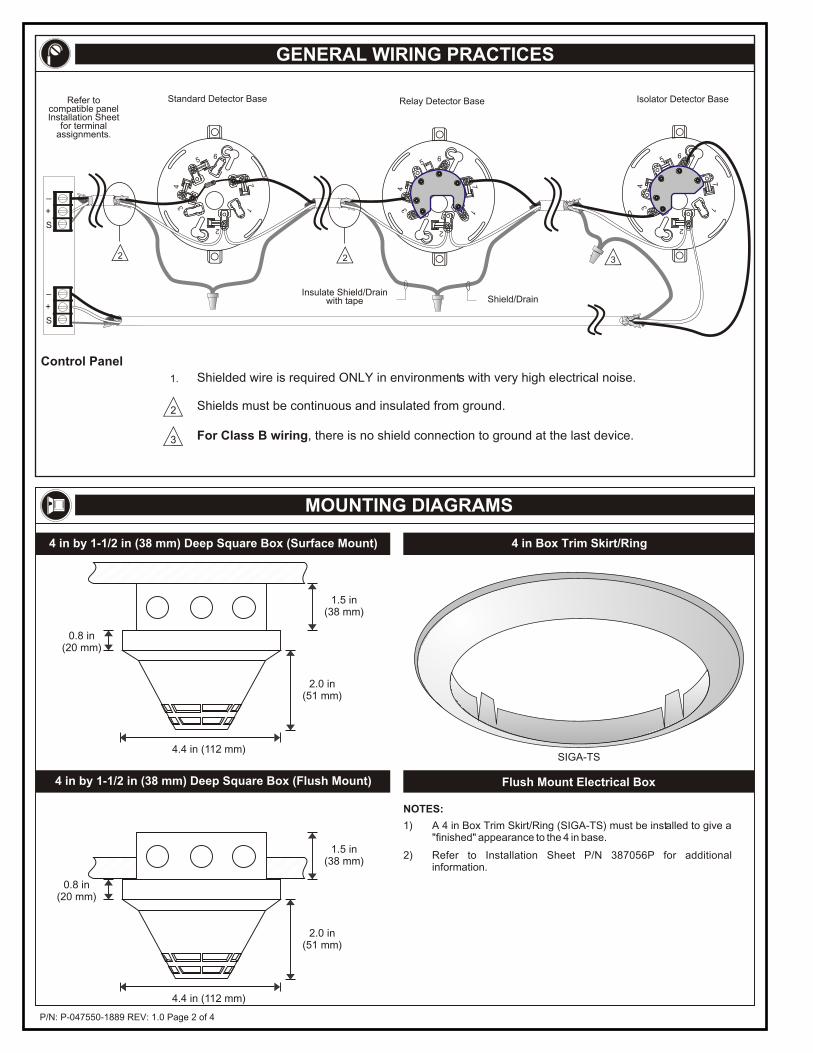
P/N: P-047550-1889 REV: 1.0 Page 2 of 4
GENERAL WIRING PRACTICES
MOUNTING DIAGRAMS
4.4 in (112 mm)
1.5 in(38 mm)
2.0 in(51 mm)
0.8 in(20 mm)
1.5 in(38 mm)
4.4 in (112 mm)
2.0 in(51 mm)
0.8 in(20 mm)
4 in by 1-1/2 in (38 mm) Deep Square Box (Flush Mount)
4 in by 1-1/2 in (38 mm) Deep Square Box (Surface Mount) 4 in Box Trim Skirt/Ring
Flush Mount Electrical Box
1) A 4 in Box Trim Skirt/Ring (SIGA-TS) must be installed to give a "finished" appearance to the 4 in base.
2) Refer to Installation Sheet P/N 387056P for additional information.
NOTES:
SIGA-TS
For Class B wiring, there is no shield connection to ground at the last device.
Control Panel
3
1.
2
Standard Detector Base
2
Relay Detector Base
Insulate Shield/Drainwith tape Shield/Drain
2
56
34
17
2
Isolator Detector Base
3
56
34
17
2
56
34
17
2
Shields must be continuous and insulated from ground.
Shielded wire is required ONLY in environments with very high electrical noise.
+
_
S
+
_
S
Refer tocompatible panelInstallation Sheet
for terminalassignments.
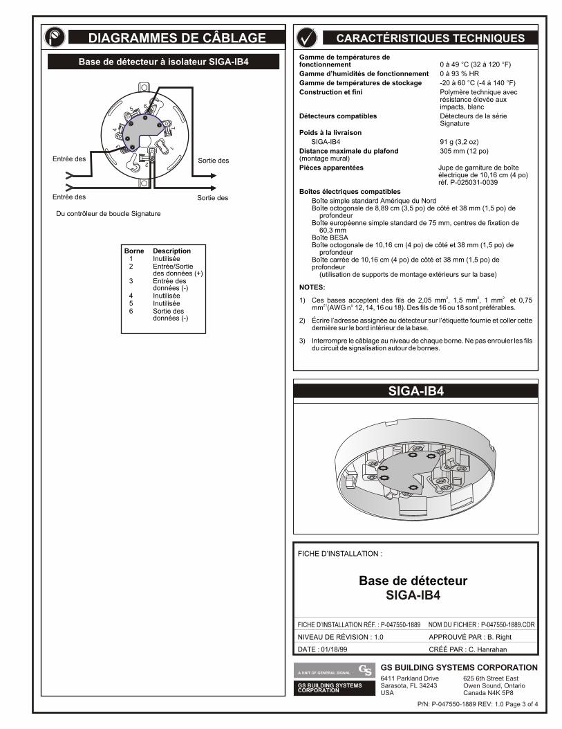
GS BUILDING SYSTEMSCORPORATION
A UNIT OF GENERAL SIGNALGS BUILDING SYSTEMS CORPORATION6411 Parkland DriveSarasota, FL 34243USA
625 6th Street EastOwen Sound, OntarioCanada N4K 5P8
Gamme de températures de fonctionnement 0 à 49 C (32 à 120 F)
Gamme d’humidités de fonctionnement 0 à 93 % HR
Gamme de températures de stockage -20 à 60 C (-4 à 140 F)
Construction et fini Polymère technique avec résistance élevée aux impacts, blanc
Détecteurs compatibles Détecteurs de la sérieSignature
Poids à la livraison
SIGA-IB4 91 g (3,2 oz)
Distance maximale du plafond 305 mm (12 po)(montage mural)
Pièces apparentées Jupe de garniture de boîteélectrique de 10,16 cm (4 po) réf. P-025031-0039
Boîtes électriques compatibles
Boîte simple standard Amérique du NordBoîte octogonale de 8,89 cm (3,5 po) de côté et 38 mm (1,5 po) de profondeurBoîte européenne simple standard de 75 mm, centres de fixation de 60,3 mmBoîte BESABoîte octogonale de 10,16 cm (4 po) de côté et 38 mm (1,5 po) de profondeurBoîte carrée de 10,16 cm (4 po) de côté et 38 mm (1,5 po) de profondeur (utilisation de supports de montage extérieurs sur la base)
NOTES:
2 2 2 1) Ces bases acceptent des fils de 2,05 mm , 1,5 mm , 1 mm et 0,75 21mm (AWG n 12, 14, 16 ou 18). Des fils de 16 ou 18 sont préférables.
2) Écrire l’adresse assignée au détecteur sur l’étiquette fournie et coller cette dernière sur le bord intérieur de la base.
3) Interrompre le câblage au niveau de chaque borne. Ne pas enrouler les fils du circuit de signalisation autour de bornes.
° °
° °
°
SIGA-IB4
CARACTÉRISTIQUES TECHNIQUES
DATE : 01/18/99
FICHE D’INSTALLATION :
FICHE D’INSTALLATION RÉF. : P-047550-1889 NOM DU FICHIER : P-047550-1889.CDR
NIVEAU DE RÉVISION : 1.0
CRÉÉ PAR : C. Hanrahan
APPROUVÉ PAR : B. Right
Base de détecteurSIGA-IB4
DIAGRAMMES DE CÂBLAGE
Base de détecteur à isolateur SIGA-IB4
56
34
17
2
Entrée des
Du contrôleur de boucle Signature
Entrée des Sortie des
Sortie des
Borne Description1 Inutilisée2 Entrée/Sortie
des données (+)3 Entrée des
données (-)4 Inutilisée5 Inutilisée6 Sortie des
données (-)
P/N: P-047550-1889 REV: 1.0 Page 3 of 4
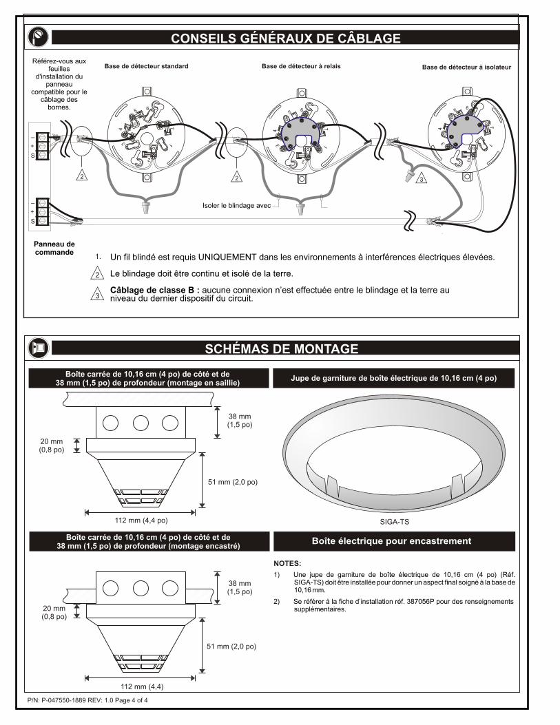
P/N: P-047550-1889 REV: 1.0 Page 4 of 4
112 mm (4,4 po)
38 mm(1,5 po)
51 mm (2,0 po)
20 mm(0,8 po)
Boîte carrée de 10,16 cm (4 po) de côté et de38 mm (1,5 po) de profondeur (montage en saillie)
38 mm(1,5 po)
112 mm (4,4)
51 mm (2,0 po)
20 mm(0,8 po)
Boîte carrée de 10,16 cm (4 po) de côté et de38 mm (1,5 po) de profondeur (montage encastré)
Jupe de garniture de boîte électrique de 10,16 cm (4 po)
SIGA-TS
1) Une jupe de garniture de boîte électrique de 10,16 cm (4 po) (Réf. SIGA-TS) doit être installée pour donner un aspect final soigné à la base de 10,16 mm.
2) Se référer à la fiche d’installation réf. 387056P pour des renseignements supplémentaires.
NOTES:
Boîte électrique pour encastrement
CONSEILS GÉNÉRAUX DE CÂBLAGE
SCHÉMAS DE MONTAGE
Un fil blindé est requis UNIQUEMENT dans les environnements à interférences électriques élevées.
Le blindage doit être continu et isolé de la terre.
Câblage de classe B : aucune connexion n’est effectuée entre le blindage et la terre au niveau du dernier dispositif du circuit.
Panneau de commande
Isoler le blindage avec
3
1.
2
2 2
56
34
17
2
3
56
34
17
2
56
34
17
2
Base de détecteur standard Base de détecteur à relais Base de détecteur à isolateur
+
_
S
+
_
S
Référez-vous aux feuilles
d'installation du panneau
compatible pour le câblage des
bornes.
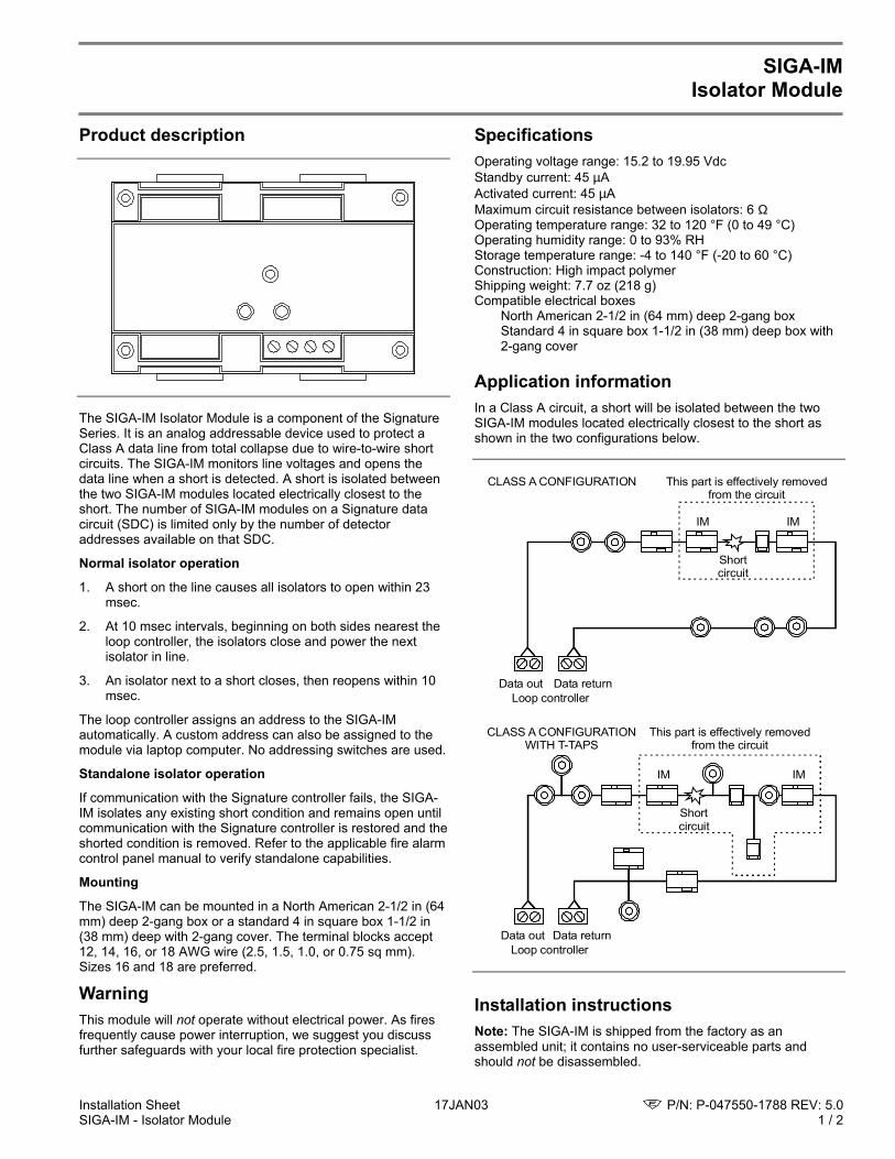
Installation Sheet 17JAN03 P/N: P-047550-1788 REV: 5.0SIGA-IM - Isolator Module 1 / 2
SIGA-IMIsolator Module
Product description
The SIGA-IM Isolator Module is a component of the SignatureSeries. It is an analog addressable device used to protect aClass A data line from total collapse due to wire-to-wire shortcircuits. The SIGA-IM monitors line voltages and opens thedata line when a short is detected. A short is isolated betweenthe two SIGA-IM modules located electrically closest to theshort. The number of SIGA-IM modules on a Signature datacircuit (SDC) is limited only by the number of detectoraddresses available on that SDC.
Normal isolator operation
1. A short on the line causes all isolators to open within 23msec.
2. At 10 msec intervals, beginning on both sides nearest theloop controller, the isolators close and power the nextisolator in line.
3. An isolator next to a short closes, then reopens within 10msec.
The loop controller assigns an address to the SIGA-IMautomatically. A custom address can also be assigned to themodule via laptop computer. No addressing switches are used.
Standalone isolator operation
If communication with the Signature controller fails, the SIGA-IM isolates any existing short condition and remains open untilcommunication with the Signature controller is restored and theshorted condition is removed. Refer to the applicable fire alarmcontrol panel manual to verify standalone capabilities.
Mounting
The SIGA-IM can be mounted in a North American 2-1/2 in (64mm) deep 2-gang box or a standard 4 in square box 1-1/2 in(38 mm) deep with 2-gang cover. The terminal blocks accept12, 14, 16, or 18 AWG wire (2.5, 1.5, 1.0, or 0.75 sq mm).Sizes 16 and 18 are preferred.
WarningThis module will not operate without electrical power. As firesfrequently cause power interruption, we suggest you discussfurther safeguards with your local fire protection specialist.
SpecificationsOperating voltage range: 15.2 to 19.95 VdcStandby current: 45 µAActivated current: 45 µAMaximum circuit resistance between isolators: 6 ΩOperating temperature range: 32 to 120 °F (0 to 49 °C)Operating humidity range: 0 to 93% RHStorage temperature range: -4 to 140 °F (-20 to 60 °C)Construction: High impact polymerShipping weight: 7.7 oz (218 g)Compatible electrical boxes
North American 2-1/2 in (64 mm) deep 2-gang boxStandard 4 in square box 1-1/2 in (38 mm) deep box with2-gang cover
Application informationIn a Class A circuit, a short will be isolated between the twoSIGA-IM modules located electrically closest to the short asshown in the two configurations below.
This part is effectively removed from the circuit
IM IM
Short circuit
Data outLoop controller
Data return
CLASS A CONFIGURATION
This part is effectively removed from the circuit
IM IM
Short circuit
Data outLoop controller
Data return
CLASS A CONFIGURATIONWITH T-TAPS
Installation instructionsNote: The SIGA-IM is shipped from the factory as anassembled unit; it contains no user-serviceable parts andshould not be disassembled.
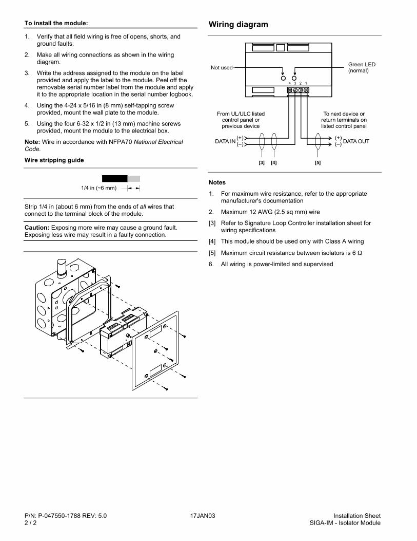
P/N: P-047550-1788 REV: 5.0 17JAN03 Installation Sheet2 / 2 SIGA-IM - Isolator Module
To install the module:
1. Verify that all field wiring is free of opens, shorts, andground faults.
2. Make all wiring connections as shown in the wiringdiagram.
3. Write the address assigned to the module on the labelprovided and apply the label to the module. Peel off theremovable serial number label from the module and applyit to the appropriate location in the serial number logbook.
4. Using the 4-24 x 5/16 in (8 mm) self-tapping screwprovided, mount the wall plate to the module.
5. Using the four 6-32 x 1/2 in (13 mm) machine screwsprovided, mount the module to the electrical box.
Note: Wire in accordance with NFPA70 National ElectricalCode.
Wire stripping guide
1/4 in (~6 mm)
Strip 1/4 in (about 6 mm) from the ends of all wires thatconnect to the terminal block of the module.
Caution: Exposing more wire may cause a ground fault.Exposing less wire may result in a faulty connection.
Wiring diagram
[4]
4 3 2 1
Not used Green LED(normal)
From UL/ULC listed control panel or previous device
To next device or return terminals on listed control panel
DATA IN DATA OUT(+)(–)
(+)(–)
[3] [5]
Notes
1. For maximum wire resistance, refer to the appropriatemanufacturer's documentation
2. Maximum 12 AWG (2.5 sq mm) wire
[3] Refer to Signature Loop Controller installation sheet forwiring specifications
[4] This module should be used only with Class A wiring
[5] Maximum circuit resistance between isolators is 6 Ω
6. All wiring is power-limited and supervised
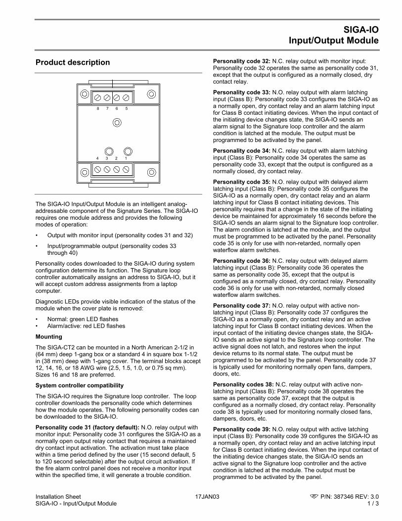
Installation Sheet 17JAN03 P/N: 387346 REV: 3.0SIGA-IO - Input/Output Module 1 / 3
SIGA-IOInput/Output Module
Product description
1234
5678
The SIGA-IO Input/Output Module is an intelligent analog-addressable component of the Signature Series. The SIGA-IOrequires one module address and provides the followingmodes of operation:
• Output with monitor input (personality codes 31 and 32)
• Input/programmable output (personality codes 33through 40)
Personality codes downloaded to the SIGA-IO during systemconfiguration determine its function. The Signature loopcontroller automatically assigns an address to SIGA-IO, but itwill accept custom address assignments from a laptopcomputer.
Diagnostic LEDs provide visible indication of the status of themodule when the cover plate is removed:
• Normal: green LED flashes• Alarm/active: red LED flashes
Mounting
The SIGA-CT2 can be mounted in a North American 2-1/2 in(64 mm) deep 1-gang box or a standard 4 in square box 1-1/2in (38 mm) deep with 1-gang cover. The terminal blocks accept12, 14, 16, or 18 AWG wire (2.5, 1.5, 1.0, or 0.75 sq mm).Sizes 16 and 18 are preferred.
System controller compatibility
The SIGA-IO requires the Signature loop controller. The loopcontroller downloads the personality code which determineshow the module operates. The following personality codes canbe downloaded to the SIGA-IO.
Personality code 31 (factory default): N.O. relay output withmonitor input: Personality code 31 configures the SIGA-IO as anormally open output relay contact that requires a maintaineddry contact input activation. The activation must take placewithin a time period defined by the user (15 second default, 5to 120 second selectable) after the output circuit activation. Ifthe fire alarm control panel does not receive a monitor inputwithin the specified time, it will generate a trouble condition.
Personality code 32: N.C. relay output with monitor input:Personality code 32 operates the same as personality code 31,except that the output is configured as a normally closed, drycontact relay.
Personality code 33: N.O. relay output with alarm latchinginput (Class B): Personality code 33 configures the SIGA-IO asa normally open, dry contact relay and an alarm latching inputfor Class B contact initiating devices. When the input contact ofthe initiating device changes state, the SIGA-IO sends analarm signal to the Signature loop controller and the alarmcondition is latched at the module. The output must beprogrammed to be activated by the panel.
Personality code 34: N.C. relay output with alarm latchinginput (Class B): Personality code 34 operates the same aspersonality code 33, except that the output is configured as anormally closed, dry contact relay.
Personality code 35: N.O. relay output with delayed alarmlatching input (Class B): Personality code 35 configures theSIGA-IO as a normally open, dry contact relay and an alarmlatching input for Class B contact initiating devices. Thispersonality requires that a change in the state of the initiatingdevice be maintained for approximately 16 seconds before theSIGA-IO sends an alarm signal to the Signature loop controller.The alarm condition is latched at the module, and the outputmust be programmed to be activated by the panel. Personalitycode 35 is only for use with non-retarded, normally openwaterflow alarm switches.
Personality code 36: N.C. relay output with delayed alarmlatching input (Class B): Personality code 36 operates thesame as personality code 35, except that the output isconfigured as a normally closed, dry contact relay. Personalitycode 36 is only for use with non-retarded, normally closedwaterflow alarm switches.
Personality code 37: N.O. relay output with active non-latching input (Class B): Personality code 37 configures theSIGA-IO as a normally open, dry contact relay and an activelatching input for Class B contact initiating devices. When theinput contact of the initiating device changes state, the SIGA-IO sends an active signal to the Signature loop controller. Theactive signal does not latch, and restores when the inputdevice returns to its normal state. The output must beprogrammed to be activated by the panel. Personality code 37is typically used for monitoring normally open fans, dampers,doors, etc.
Personality codes 38: N.C. relay output with active non-latching input (Class B): Personality code 38 operates thesame as personality code 37, except that the output isconfigured as a normally closed, dry contact relay. Personalitycode 38 is typically used for monitoring normally closed fans,dampers, doors, etc.
Personality code 39: N.O. relay output with active latchinginput (Class B): Personality code 39 configures the SIGA-IO asa normally open, dry contact relay and an active latching inputfor Class B contact initiating devices. When the input contact ofthe initiating device changes state, the SIGA-IO sends anactive signal to the Signature loop controller and the activecondition is latched at the module. The output must beprogrammed to be activated by the panel.
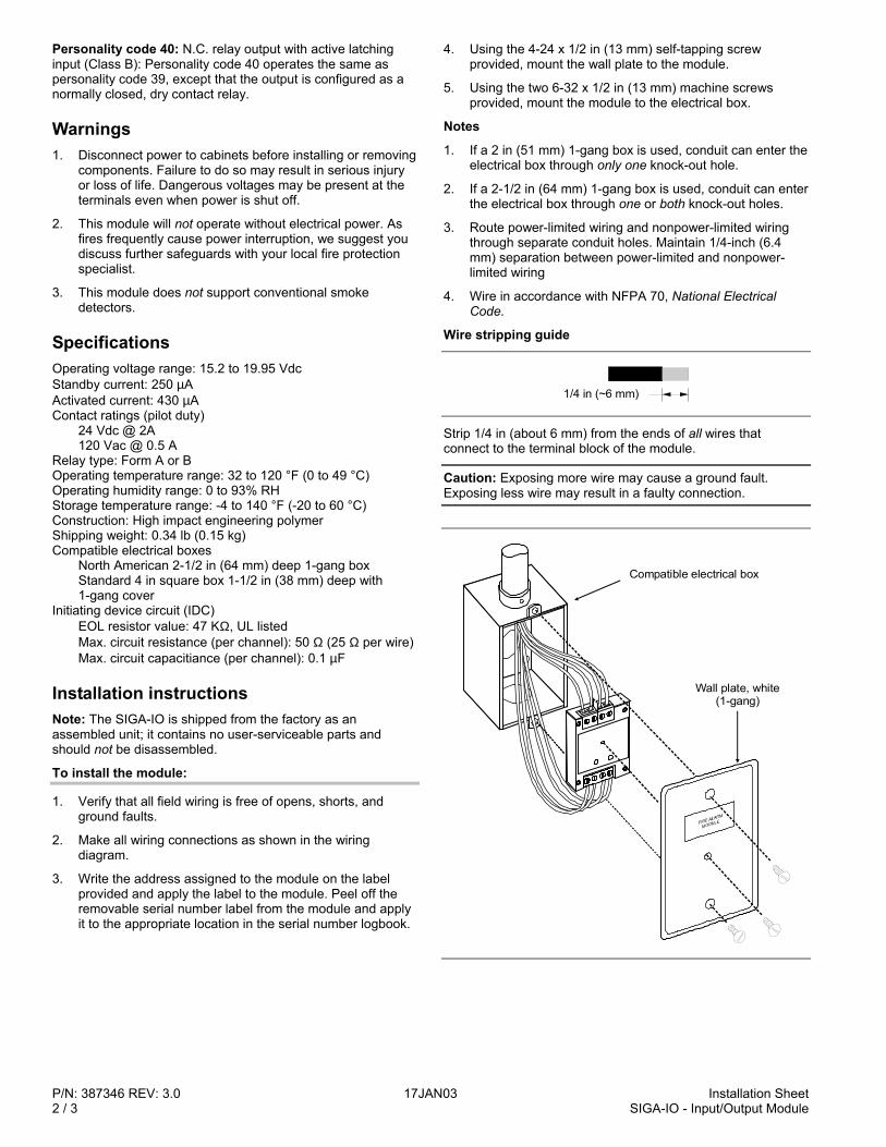
P/N: 387346 REV: 3.0 17JAN03 Installation Sheet2 / 3 SIGA-IO - Input/Output Module
Personality code 40: N.C. relay output with active latchinginput (Class B): Personality code 40 operates the same aspersonality code 39, except that the output is configured as anormally closed, dry contact relay.
Warnings1. Disconnect power to cabinets before installing or removing
components. Failure to do so may result in serious injuryor loss of life. Dangerous voltages may be present at theterminals even when power is shut off.
2. This module will not operate without electrical power. Asfires frequently cause power interruption, we suggest youdiscuss further safeguards with your local fire protectionspecialist.
3. This module does not support conventional smokedetectors.
SpecificationsOperating voltage range: 15.2 to 19.95 VdcStandby current: 250 µAActivated current: 430 µAContact ratings (pilot duty)
24 Vdc @ 2A120 Vac @ 0.5 A
Relay type: Form A or BOperating temperature range: 32 to 120 °F (0 to 49 °C)Operating humidity range: 0 to 93% RHStorage temperature range: -4 to 140 °F (-20 to 60 °C)Construction: High impact engineering polymerShipping weight: 0.34 lb (0.15 kg)Compatible electrical boxes
North American 2-1/2 in (64 mm) deep 1-gang boxStandard 4 in square box 1-1/2 in (38 mm) deep with1-gang cover
Initiating device circuit (IDC)EOL resistor value: 47 KΩ, UL listedMax. circuit resistance (per channel): 50 Ω (25 Ω per wire)Max. circuit capacitiance (per channel): 0.1 µF
Installation instructionsNote: The SIGA-IO is shipped from the factory as anassembled unit; it contains no user-serviceable parts andshould not be disassembled.
To install the module:
1. Verify that all field wiring is free of opens, shorts, andground faults.
2. Make all wiring connections as shown in the wiringdiagram.
3. Write the address assigned to the module on the labelprovided and apply the label to the module. Peel off theremovable serial number label from the module and applyit to the appropriate location in the serial number logbook.
4. Using the 4-24 x 1/2 in (13 mm) self-tapping screwprovided, mount the wall plate to the module.
5. Using the two 6-32 x 1/2 in (13 mm) machine screwsprovided, mount the module to the electrical box.
Notes
1. If a 2 in (51 mm) 1-gang box is used, conduit can enter theelectrical box through only one knock-out hole.
2. If a 2-1/2 in (64 mm) 1-gang box is used, conduit can enterthe electrical box through one or both knock-out holes.
3. Route power-limited wiring and nonpower-limited wiringthrough separate conduit holes. Maintain 1/4-inch (6.4mm) separation between power-limited and nonpower-limited wiring
4. Wire in accordance with NFPA 70, National ElectricalCode.
Wire stripping guide
1/4 in (~6 mm)
Strip 1/4 in (about 6 mm) from the ends of all wires thatconnect to the terminal block of the module.
Caution: Exposing more wire may cause a ground fault.Exposing less wire may result in a faulty connection.
Compatible electrical box
Wall plate, white(1-gang)
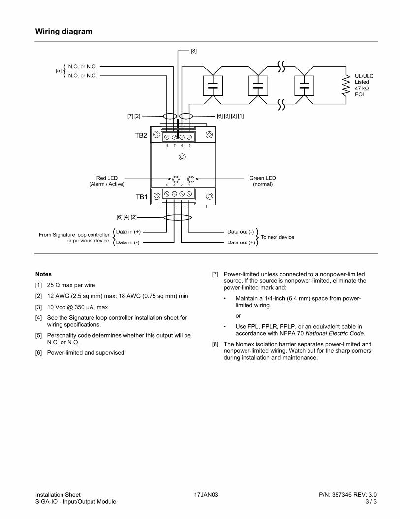
Installation Sheet 17JAN03 P/N: 387346 REV: 3.0SIGA-IO - Input/Output Module 3 / 3
Wiring diagram
Data in (+)
TB1
TB2
Data in (-)From Signature loop controller
or previous device
Data out (-)
Data out (+)To next device
N.O. or N.C.
[1][2][3]
[4]
[5]UL/ULCListed47 kEOL
Ω
[6][7]
[6]
[2]
N.O. or N.C.
[8]
[2]
1234
5678
Red LED(Alarm / Active)
Green LED(normal)
Notes
[1] 25 Ω max per wire
[2] 12 AWG (2.5 sq mm) max; 18 AWG (0.75 sq mm) min
[3] 10 Vdc @ 350 µA, max
[4] See the Signature loop controller installation sheet forwiring specifications.
[5] Personality code determines whether this output will beN.C. or N.O.
[6] Power-limited and supervised
[7] Power-limited unless connected to a nonpower-limitedsource. If the source is nonpower-limited, eliminate thepower-limited mark and:
• Maintain a 1/4-inch (6.4 mm) space from power-limited wiring.
or
• Use FPL, FPLR, FPLP, or an equivalent cable inaccordance with NFPA 70 National Electric Code.
[8] The Nomex isolation barrier separates power-limited andnonpower-limited wiring. Watch out for the sharp cornersduring installation and maintenance.

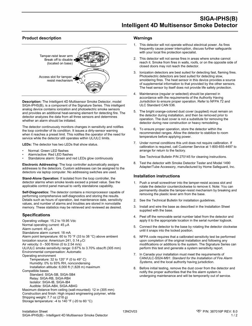
Installation Sheet 13NOV03 P/N: 387016P REV: 8.0 SIGA-IPHS(B) - Intelligent 4D Multisensor Smoke Detector 1 / 2
SIGA-IPHS(B) Intelligent 4D Multisensor Smoke Detector
Product description
Tamper-reist lever armBreak off to disable
(located on base)
Access slot for tamper-resist mechanism
Description: The Intelligent 4D Multisensor Smoke Detector, model SIGA-IPHS(B), is a component of the Signature Series. This intelligent analog device contains ionization and photoelectric smoke sensors and provides an additional heat-sensing element for detecting fire. The detector analyzes the data from all three sensors and determines whether an alarm should be initiated.
The detector continuously monitors changes in sensitivity and notifies the loop controller of its condition. It issues a dirty-sensor warning when it reaches a preset limit. This notifies the operator of the need for service while the detector still operates within UL/ULC limits.
LEDs: The detector has two LEDs that show status.
• Normal: Green LED flashes • Alarm/active: Red LED flashes • Standalone alarm: Green and red LEDs glow continuously
Electronic Addressing: The loop controller automatically assigns addresses to the detectors. Custom addresses can be assigned to the detectors via laptop computer. No addressing switches are used.
Stand-Alone Operation: If isolated from the loop controller, the detector alarms when smoke levels exceed a preset value. See the applicable control panel manual to verify standalone capability.
Self-Diagnostics: The detector contains a microprocessor capable of performing comprehensive self-diagnostics and storing the results. Details such as hours of operation, last maintenance date, sensitivity values, and number of alarms and troubles are stored in nonvolatile memory. These statistics may be retrieved and reviewed as desired.
Specifications Operating voltage: 15.2 to 19.95 Vdc Normal operating current: 45 µA Alarm current: 45 µA Standalone alarm current: 18 mA Alarm point temperature: 60 to 70 °F (33 to 38 °C) above ambient Ionization source: Americium 241, 0.14 µCi Air velocity: 0 - 500 ft/min (0 to 2.54 m/s) ULI/ULC smoke sensitivity range: 0.67% to 3.70% obsc/ft (305 mm) Environmental compensation: Automatic Operating environment
Temperature: 32 to 120° F (0 to 49° C) Humidity: 0% to 93% RH, noncondensing Installation altitude: 6,000 ft (1,828 m) maximum
Compatible bases Standard: SIGA-SB, SIGA-SB4 Relay: SIGA-RB, SIGA-RB4 Isolator: SIGA-IB, SIGA-IB4 Audible: SIGA-AB4, SIGA-AB4G Maximum distance from ceiling (wall-mounted): 12 in (305 mm) Construction and finish: High impact engineering polymer, white Shipping weight: 7.7 oz (218 g) Storage temperature: -4 to 140 °F (-20 to 60 °C)
Warnings 1. This detector will not operate without electrical power. As fires
frequently cause power interruption, discuss further safeguards with your local fire protection specialist.
2. This detector will not sense fires in areas where smoke cannot reach it. Smoke from fires in walls, roofs, or on the opposite side of closed doors may not reach the detector.
3. Ionization detectors are best suited for detecting fast, flaming fires. Photoelectric detectors are best suited for detecting slow, smoldering fires. The heat sensor in this device provides a source of supplemental information to that provided by the other sensors. The heat sensor by itself does not provide life safety protection.
4. Maintenance (regular or selected) should be planned in accordance with the requirements of the Authority Having Jurisdiction to ensure proper operation. Refer to NFPA 72 and ULC Standard CAN 536.
5. The bright orange-colored dust cover (supplied) must remain on the detector during installation, and then be removed prior to operation. The dust cover is not a substitute for removing the detector during new construction or heavy remodeling.
6. To ensure proper operation, store the detector within the recommended ranges. Allow the detector to stabilize to room temperature before applying power.
7. Under normal conditions this unit does not require calibration. If calibration is required, call Customer Service at 1-800-655-4497 to arrange for return to the factory.
See Technical Bulletin P/N 270145 for cleaning instructions.
8. Test the detector with Smoke Detector Tester and Model 1490 Adapter/Tube Accessory, manufactured by Home Safeguard, Inc.
Installation instructions 1. Push a small screwdriver into the tamper-resist access slot and
rotate the detector counterclockwise to remove it. Note: You can permanently disable the tamper-resist mechanism by breaking and removing the plastic lever arm from the base.
2. See the Technical Bulletin for installation guidelines.
3. Install and wire the base as described in the Installation Sheet supplied with the base.
4. Peel off the removable serial number label from the detector and apply it to the appropriate location in the serial number logbook.
5. Connect the detector to the base by rotating the detector clockwise until it snaps into the locked position.
6. NFPA code requires that a calibrated sensitivity test be performed upon completion of the original installation and following any modifications or additions to the system. The Signature Series can perform this test and generate a system sensitivity report.
7. In Canada your installation must meet the requirements of CAN/ULC-S524-M91: Standard for the Installation of Fire Alarm Systems, and the local authority having jurisdiction.
8. Before initial testing, remove the dust cover from the detector and notify the proper authorities that the fire alarm system is undergoing maintenance and will be temporarily out of service.
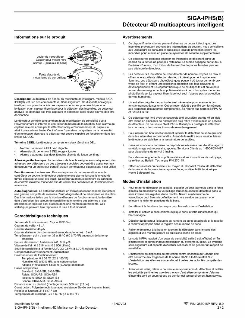
Installation Sheet 13NOV03 P/N: 387016P REV: 8.0 SIGA-IPHS(B) - Intelligent 4D Multisensor Smoke Detector 2 / 2
SIGA-IPHS(B) Détecteur 4D multicapteurs intelligent
Informations sur le produit
Levier de verrouillage- Casser pour mettre hors
service - (situé sur la base)
Fente d'accès du mécanisme de verrouillage
Description: Le détecteur de fumée 4D multicapteurs intelligent, modèle SIGA-IPHS(B), est l'un des composants du Série Signature. Ce dispositif analogique intelligent comprend à la fois des capteurs de fumée photoélectrique et à ionisation et un capteur thermique pour la détection des incendies. Le détecteur analyse les données des trois capteurs et détermine ainsi si une alarme doit être déclenchée.
Le détecteur contrôle constamment toute modification de sensibilité due à l'environnement et informe le contrôleur de boucle de la situation. Une alarme de capteur sale est émise par le détecteur lorsque l'encrassement du capteur a atteint une certaine limite. Ceci informe l'opérateur du système de la nécessité d'un nettoyage alors que le détecteur est encore capable de fonctionner dans les limites UL/ULC.
Témoins à DEL: Le détecteur comprennent deux témoins à DEL.
• Normal: Le témoin à DEL vert clignote • Alarme/actif: Le témoin à DEL rouge clignote • Alarme autonome: Les deux témoins allumés de façon continue
Adressage électronique: Le contrôleur de boucle assigne automatiquement des adresses aux détecteurs ou des adresses spéciales peuvent être assignées aux détecteurs via un ordinateur portatif. Aucun commutateur d'adressage n'est utilisé.
Fonctionnement autonome: En cas de panne de communication avec le contrôleur de boucle, le détecteur déclenche une alarme lorsque le niveau de fumée dépasse un seuil pré-établi. Se référer au manuel pertinent du panneau de contrôle d'alarme d'incendie afin de vérifier les possibilités du fonctionnement autonome.
Auto-diagnostics: Le détecteur contient un microprocesseur capable d'effectuer une gamme complète de mesures d'auto-diagnostic et de mémoriser les résultats. Des informations telles que le nombre d'heures de fonctionnement, la dernière date d'entretien, les valeurs de sensibilité et le nombre des alarmes et des problèmes enregistrés sont stockés dans une mémoire permanente. Ces statistiques peuvent être rappelées et lues à tout moment.
Caractéristiques techniques Tension de fonctionnement: 15,2 à 19,95 Vcc Courant de veille: 45 µA Courant d'alarme: 45 µA Courant d'alarme (fonctionnement en mode autonome): 18 mA Température - point d’alarme: 33 à 38 ºC (60 à 70 ºF) audessus de la temp.
ambiante Source d’ionisation: Américium 241, 0,14 µCi Vitesse de l’air: 0 à 2,54 m/s (0 à 500 pi/min) Seuil de sensibilité à la fumée ULI/ULC: 0,67% à 3,70 % obsc/pi (305 mm) Compensation/environnement: Automatique Environnement de fonctionnement:
Température: 0 à 38 ºC (32 à 100 ºF) Humidité: 0% à 93% HR, sans condensation Altitude d'installation: 1.828 m (6.000 pi) maximum
Bases compatibles Standard: SIGA-SB, SIGA-SB4 Relais: SIGA-RB, SIGA-RB4 Isolateurs: SIGA-IB, SIGA-IB4 Sonore: SIGA-AB4, SIGA-AB4G
Distance max. du plafond (montage mural): 305 mm (12 po) Construction: Polymère technique avec résistance élevée aux impacts, blanc Poids à la livraison: 218 g (7,7 oz) Température de stockage: -20 à 60 ºC (-4 à 140 ºF)
Avertissements 1. Ce dispositif ne fonctionne pas en l'absence de courant électrique. Les
incendies provoquant souvent des interruptions de courant, nous conseillons aux utilisateurs de consulter le spécialiste local de protection contre les incendies pour la mise en place de systèmes de sécurité supplémentaires.
2. Ce détecteur ne peut pas détecter les incendies se déclarant dans un endroit où la fumée ne peut pas l'atteindre. La fumée dégagée par un feu à l'intérieur d'un mur, d'un toit ou de l'autre côté de portes fermées peut ne pas atteindre le détecteur.
3. Les détecteurs à ionisation peuvent détecter de nombreux types de feux et offrent une excellente détection des feux à développement rapide avec flammes. Les détecteurs photoélectriques peuvent dé-tecter de nombreux types de feux et offrent une excellente détection des feux couvants à développement lent. Le capteur thermique de ce dispositif est prévu pour fournir des renseignements supplémen-taires à ceux du capteur de fumée photoélectrique. Le capteur thermique tout seul n’assure pas la protection de vies humaines.
4. Un entretien (régulier ou particulier) est nécessaire pour assurer le bon fonctionnement du système. Cet entretien doit être planifié con-formément aux exigences des autorités compétentes. Se référer aux normes NFPA 72 et CAN/ULC 536.
5. Ce détecteur est livré avec un couvercle anti-poussière orange vif qui doit être laissé en place lors de l'installation puis retiré avant la mise en service du détecteur. Ce couvercle N'est PAS suffisant pour protéger le détecteur lors de travaux de construction ou de réamé-nagement.
6. Pour assurer un bon fonctionnement, stocker le détecteur de sorte qu'il soit dans les intervalles recommandés. Avant de le mettre sous tension, laisser le détecteur se stabiliser à la température de la pièce.
7. Dans les conditions normales ce dispositif ne nécessite pas d'étalonnage. Si un étalonnage est nécessaire, appelez Service à Clients au 1-800-655-4497 pour dispositions de renvoi à l’usine.
Pour des renseignements supplémentaires et les instructions de nettoyage, se référer au Bulletin Technique P/N 270145.
8. Effectuer un essai du détecteur au moyen du dispositif d'essai de détecteur de fumée et de l'accessoire adaptateur/tube, modèle 1490, fabriqué par Home Safeguard Inc.
Modes d’installation 1. Pour retirer le détecteur de sa base, pousser un petit tournevis dans la fente
d'accès du mécanisme de vérouillage tout en tournant le détecteur dans le sens inverse des aiguilles d'une montre. Note: Le mécanisme de verrouillage peut être mis définitivement hors service en cassant et en enlevant le levier en plastique de la base.
2. Se référer à la brochure technique pour les instructions d'installation.
3. Installer et câbler la base comme expliqué dans la fiche d'installation qui l'accompagne.
4. Décoller du détecteur l'étiquette de numéro de série détachable et la recoller à l'endroit approprié dans le registre des numéros de série.
5. Relier le détecteur à la base en tournant le détecteur dans le sens des aiguilles d'une montre jusqu'à ce qu'il s'enclenche en place.
6. Le code NFPA requiert q'un essai de sensibilité calibré soit effectué en fin d'installation et après chaque modification du système ou ajout. Le système série Signature est capable d'effectuer cet essai et de générer un rapport de sensibilité.
7. L'installation de dispositifs de protection contre l'incendie au Canada doit être conforme aux exigences de la norme CAN/ULC-S524-M91 Sur L'installation des Alarmes à Incendie, et à celles des autorités compétentes locales.
8. Avant essai initial, retirer le couvercle anti-poussières du détecteur et notifier les autorités pertinentes que des travaux d'entretien du système d'alarme d'incendie sont en cours et que ce dernier est temporairement hors service.

PRODUCT INFORMATION
INSTALLATION SHEET
DATE: 28APR99
SHEET P/N: P-047550-1898 FILE NAME: P-047550-1898.CDR
REVISION LEVEL: 1.0
CREATED BY: D. Chinell
APPROVED BY: R. Right
WARNINGS
RELATED DOCUMENTSTechnical Bulletin (P/N 270145)
INSTALLATION INSTRUCTIONS
SPECIFICATIONS
PRODUCT DIAGRAM
Tamper-Resist Lever Arm- Break off to disable -
(Located on Base)
Access Slot forTamper-Resist Mechanism
SIGA-IPHSIIntelligent 4D Multisensor
Smoke Detector
Description: The Intelligent 4D Multisensor Smoke Detector (model IPHSI) is a component of the Signature Series. This intelligent analog device contains ionization and photoelectric smoke sensors and provides an additional heat sensing element for detecting fire. The detector analyzes the data from all three sensors and determines whether an alarm should be initiated.
The detector continuously monitors changes in sensitivity and notifies the loop controller of its condition. It issues a dirty-sensor warning when it reaches a preset limit. This notifies the operator of the need for service while the detector still operates.
LEDs: The IPHSI has two LEDs that show status.
Normal: Green LED flashesAlarm/active: Red LED flashesStandalone alarm: Green and red LEDs glow continuously
Electronic Addressing: The loop controller automatically assigns addresses to the detectors. Custom addresses can be assigned to the detectors via laptop computer. No addressing switches are used.
Stand-Alone Operation: If isolated from the loop controller, the detector alarms when smoke levels exceed a preset value. See the applicable control panel manual to verify standalone capability.
Self-Diagnostics: The detector contains a microprocessor capable of performing comprehensive self-diagnostics and storing the results. Details such as hours of operation, last maintenance date, sensitivity values, and number of alarms and troubles are stored in nonvolatile memory. These statistics may be retrieved and reviewed as desired.
1) Push a small screwdriver into the tamper-resist access slot and rotate the detector counterclockwise to remove it. Note: You can permanently disable the tamper-resist mechanism by breaking and removing the plastic lever arm from the base.
2) See the Technical Bulletin for installation guidelines.
3) Install and wire the base as described in the Installation Sheet supplied with the base.
4) Peel off the removable serial number label from the detector and apply it to the appropriate location in the serial number log book.
5) Connect the detector to the base by rotating the detector clockwise until it snaps into the locked position.
6) Before initial testing, remove the dust cover from the detector and notify the proper authorities that the fire alarm system is undergoing maintenance and will be temporarily out of service.
1) This detector will NOT operate without electrical power. As fires frequently cause power interruption, discuss further safeguards with your local fire protection specialist.
2) This detector will NOT sense fires in areas where smoke cannot reach it. Smoke from fires in walls, roofs, or on the opposite side of closed doors may not reach the detector.
3) Ionization detectors are best suited for detecting fast, flaming fires. Photoelectric detectors are best suited for detecting slow, smoldering fires. The heat sensor in this device provides a source of supplemental information to that provided by the other sensors. The heat sensor by itself does NOT provide life safety protection.
4) Maintenance (regular or selected) should be planned in accordance with the requirements of the Authority Having Jurisdiction to ensure proper operation.
5) The bright orange-colored dust cover (supplied) MUST remain on the detector during installation, and then be removed prior to operation. The dust cover is NOT a substitute for removing the detector during new construction or heavy remodeling.
6) To ensure proper operation, store the detector within the
recommended ranges. Allow the detector to stabilize to room temperature before applying power.
7) Under normal conditions, this unit does not require calibration. However, if calibration is required, return to:
GS Building Systems Corporation5 North Main StreetPittsfield, ME 04967-1500
See the Technical Bulletin for cleaning instructions.
8) Test the detector with Smoke Detector Tester and Model 1490 Adapter/Tube Accessory, manufactured by Home Safeguard, Inc.
Operating voltage range: 15.2 - 19.95 VdcNormal operating current: 45 µAAlarm current: 45 µAStandalone alarm current: 18 mAAlarm point temperature range: 60 - 70 °F (33 - 38 °C) above ambientIonization source: Americium 241, 0.135 µCiAir velocity range: 0 - 500 ft/min (0 - 2.54 m/s)Operating temperature range: 32 - 100 °F (0 - 38 °C)Operating humidity range: 0 - 93 % RH, non-condensingStorage temperature range: -4 - 140 °F (-20 - 60 °C)Environmental compensation: AutomaticConstruction and finish: High impact engineering polymer, whiteCompatible bases
Standard: SB, SB4Relay: RB, RB4Isolator: IB, IB4, IBSAudible: AB4
Shipping weight: 7.7 oz (218 g)Maximum distance from ceiling (wall-mounted): 12 in (305 mm)Maximum installation altitude: 6,000 ft. (1,828 m)
EDWARDS SYSTEMS TECHNOLOGY
6411 Parkland DriveSarasota, FL 34243USA
625 6th Street EastOwen Sound, OntarioCanada N4K 5P8
TM

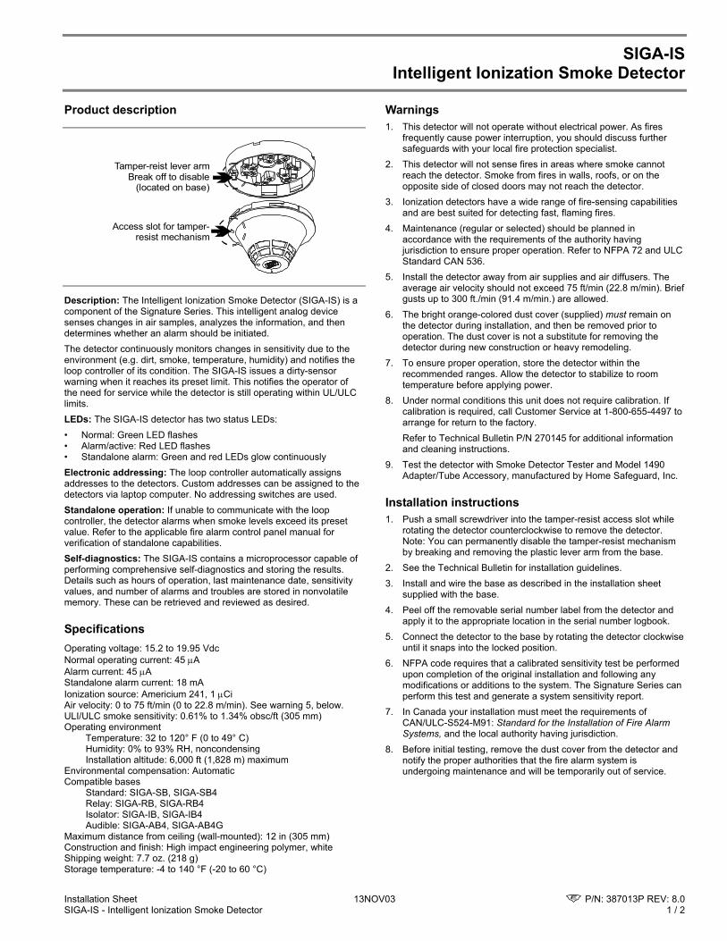
Installation Sheet 13NOV03 P/N: 387013P REV: 8.0 SIGA-IS - Intelligent Ionization Smoke Detector 1 / 2
SIGA-IS Intelligent Ionization Smoke Detector
Product description
Tamper-reist lever armBreak off to disable
(located on base)
Access slot for tamper-resist mechanism
Description: The Intelligent Ionization Smoke Detector (SIGA-IS) is a component of the Signature Series. This intelligent analog device senses changes in air samples, analyzes the information, and then determines whether an alarm should be initiated. The detector continuously monitors changes in sensitivity due to the environment (e.g. dirt, smoke, temperature, humidity) and notifies the loop controller of its condition. The SIGA-IS issues a dirty-sensor warning when it reaches its preset limit. This notifies the operator of the need for service while the detector is still operating within UL/ULC limits. LEDs: The SIGA-IS detector has two status LEDs: • Normal: Green LED flashes • Alarm/active: Red LED flashes • Standalone alarm: Green and red LEDs glow continuously Electronic addressing: The loop controller automatically assigns addresses to the detectors. Custom addresses can be assigned to the detectors via laptop computer. No addressing switches are used. Standalone operation: If unable to communicate with the loop controller, the detector alarms when smoke levels exceed its preset value. Refer to the applicable fire alarm control panel manual for verification of standalone capabilities. Self-diagnostics: The SIGA-IS contains a microprocessor capable of performing comprehensive self-diagnostics and storing the results. Details such as hours of operation, last maintenance date, sensitivity values, and number of alarms and troubles are stored in nonvolatile memory. These can be retrieved and reviewed as desired.
Specifications Operating voltage: 15.2 to 19.95 Vdc Normal operating current: 45 µA Alarm current: 45 µA Standalone alarm current: 18 mA Ionization source: Americium 241, 1 µCi Air velocity: 0 to 75 ft/min (0 to 22.8 m/min). See warning 5, below. ULI/ULC smoke sensitivity: 0.61% to 1.34% obsc/ft (305 mm) Operating environment
Temperature: 32 to 120° F (0 to 49° C) Humidity: 0% to 93% RH, noncondensing Installation altitude: 6,000 ft (1,828 m) maximum
Environmental compensation: Automatic Compatible bases Standard: SIGA-SB, SIGA-SB4 Relay: SIGA-RB, SIGA-RB4 Isolator: SIGA-IB, SIGA-IB4 Audible: SIGA-AB4, SIGA-AB4G Maximum distance from ceiling (wall-mounted): 12 in (305 mm) Construction and finish: High impact engineering polymer, white Shipping weight: 7.7 oz. (218 g) Storage temperature: -4 to 140 °F (-20 to 60 °C)
Warnings 1. This detector will not operate without electrical power. As fires
frequently cause power interruption, you should discuss further safeguards with your local fire protection specialist.
2. This detector will not sense fires in areas where smoke cannot reach the detector. Smoke from fires in walls, roofs, or on the opposite side of closed doors may not reach the detector.
3. Ionization detectors have a wide range of fire-sensing capabilities and are best suited for detecting fast, flaming fires.
4. Maintenance (regular or selected) should be planned in accordance with the requirements of the authority having jurisdiction to ensure proper operation. Refer to NFPA 72 and ULC Standard CAN 536.
5. Install the detector away from air supplies and air diffusers. The average air velocity should not exceed 75 ft/min (22.8 m/min). Brief gusts up to 300 ft./min (91.4 m/min.) are allowed.
6. The bright orange-colored dust cover (supplied) must remain on the detector during installation, and then be removed prior to operation. The dust cover is not a substitute for removing the detector during new construction or heavy remodeling.
7. To ensure proper operation, store the detector within the recommended ranges. Allow the detector to stabilize to room temperature before applying power.
8. Under normal conditions this unit does not require calibration. If calibration is required, call Customer Service at 1-800-655-4497 to arrange for return to the factory.
Refer to Technical Bulletin P/N 270145 for additional information and cleaning instructions.
9. Test the detector with Smoke Detector Tester and Model 1490 Adapter/Tube Accessory, manufactured by Home Safeguard, Inc.
Installation instructions 1. Push a small screwdriver into the tamper-resist access slot while
rotating the detector counterclockwise to remove the detector. Note: You can permanently disable the tamper-resist mechanism by breaking and removing the plastic lever arm from the base.
2. See the Technical Bulletin for installation guidelines. 3. Install and wire the base as described in the installation sheet
supplied with the base. 4. Peel off the removable serial number label from the detector and
apply it to the appropriate location in the serial number logbook. 5. Connect the detector to the base by rotating the detector clockwise
until it snaps into the locked position. 6. NFPA code requires that a calibrated sensitivity test be performed
upon completion of the original installation and following any modifications or additions to the system. The Signature Series can perform this test and generate a system sensitivity report.
7. In Canada your installation must meet the requirements of CAN/ULC-S524-M91: Standard for the Installation of Fire Alarm Systems, and the local authority having jurisdiction.
8. Before initial testing, remove the dust cover from the detector and notify the proper authorities that the fire alarm system is undergoing maintenance and will be temporarily out of service.
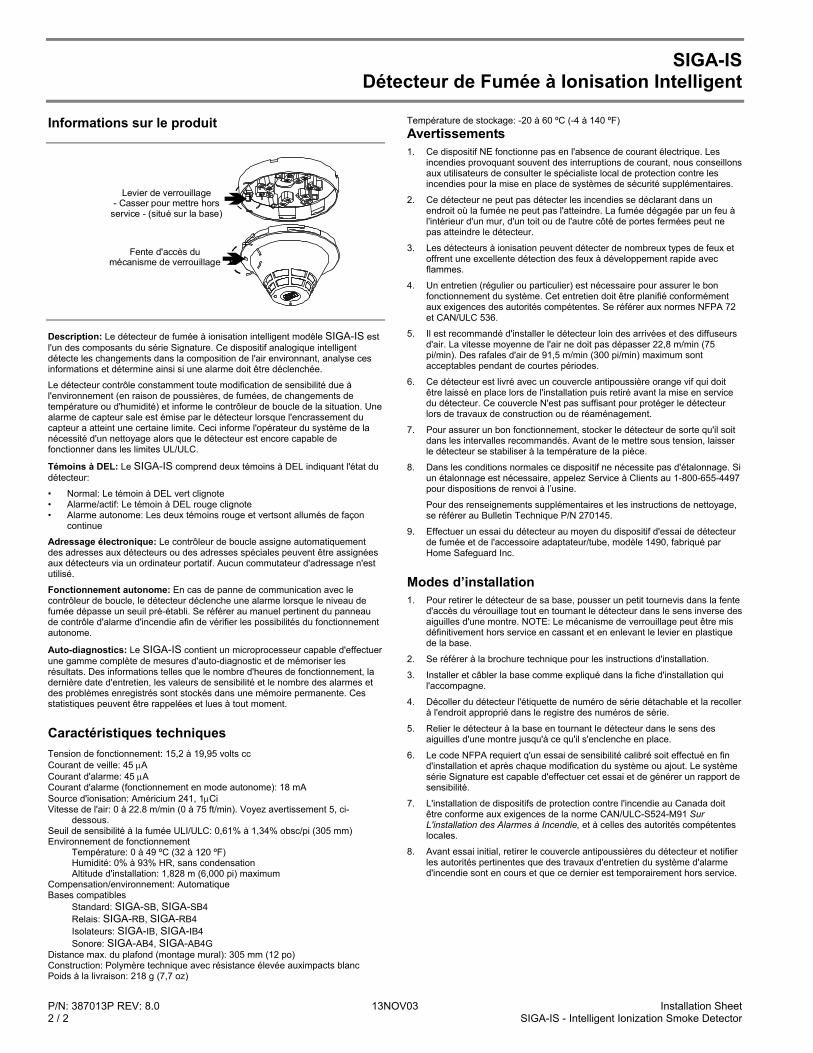
P/N: 387013P REV: 8.0 13NOV03 Installation Sheet 2 / 2 SIGA-IS - Intelligent Ionization Smoke Detector
SIGA-IS Détecteur de Fumée à Ionisation Intelligent
Informations sur le produit
Levier de verrouillage- Casser pour mettre hors
service - (situé sur la base)
Fente d'accès du mécanisme de verrouillage
Description: Le détecteur de fumée à ionisation intelligent modèle SIGA-IS est l'un des composants du série Signature. Ce dispositif analogique intelligent détecte les changements dans la composition de l'air environnant, analyse ces informations et détermine ainsi si une alarme doit être déclenchée.
Le détecteur contrôle constamment toute modification de sensibilité due à l'environnement (en raison de poussières, de fumées, de changements de température ou d'humidité) et informe le contrôleur de boucle de la situation. Une alarme de capteur sale est émise par le détecteur lorsque l'encrassement du capteur a atteint une certaine limite. Ceci informe l'opérateur du système de la nécessité d'un nettoyage alors que le détecteur est encore capable de fonctionner dans les limites UL/ULC.
Témoins à DEL: Le SIGA-IS comprend deux témoins à DEL indiquant l'état du détecteur:
• Normal: Le témoin à DEL vert clignote • Alarme/actif: Le témoin à DEL rouge clignote • Alarme autonome: Les deux témoins rouge et vertsont allumés de façon
continue
Adressage électronique: Le contrôleur de boucle assigne automatiquement des adresses aux détecteurs ou des adresses spéciales peuvent être assignées aux détecteurs via un ordinateur portatif. Aucun commutateur d'adressage n'est utilisé.
Fonctionnement autonome: En cas de panne de communication avec le contrôleur de boucle, le détecteur déclenche une alarme lorsque le niveau de fumée dépasse un seuil pré-établi. Se référer au manuel pertinent du panneau de contrôle d'alarme d'incendie afin de vérifier les possibilités du fonctionnement autonome.
Auto-diagnostics: Le SIGA-IS contient un microprocesseur capable d'effectuer une gamme complète de mesures d'auto-diagnostic et de mémoriser les résultats. Des informations telles que le nombre d'heures de fonctionnement, la dernière date d'entretien, les valeurs de sensibilité et le nombre des alarmes et des problèmes enregistrés sont stockés dans une mémoire permanente. Ces statistiques peuvent être rappelées et lues à tout moment.
Caractéristiques techniques Tension de fonctionnement: 15,2 à 19,95 volts cc Courant de veille: 45 µA Courant d'alarme: 45 µA Courant d'alarme (fonctionnement en mode autonome): 18 mA Source d'ionisation: Américium 241, 1µCi Vitesse de l'air: 0 à 22.8 m/min (0 à 75 ft/min). Voyez avertissement 5, ci-
dessous. Seuil de sensibilité à la fumée ULI/ULC: 0,61% à 1,34% obsc/pi (305 mm) Environnement de fonctionnement
Température: 0 à 49 ºC (32 à 120 ºF) Humidité: 0% à 93% HR, sans condensation Altitude d'installation: 1,828 m (6,000 pi) maximum
Compensation/environnement: Automatique Bases compatibles Standard: SIGA-SB, SIGA-SB4 Relais: SIGA-RB, SIGA-RB4 Isolateurs: SIGA-IB, SIGA-IB4 Sonore: SIGA-AB4, SIGA-AB4G Distance max. du plafond (montage mural): 305 mm (12 po) Construction: Polymère technique avec résistance élevée auximpacts blanc Poids à la livraison: 218 g (7,7 oz)
Température de stockage: -20 à 60 ºC (-4 à 140 ºF) Avertissements 1. Ce dispositif NE fonctionne pas en l'absence de courant électrique. Les
incendies provoquant souvent des interruptions de courant, nous conseillons aux utilisateurs de consulter le spécialiste local de protection contre les incendies pour la mise en place de systèmes de sécurité supplémentaires.
2. Ce détecteur ne peut pas détecter les incendies se déclarant dans un endroit où la fumée ne peut pas l'atteindre. La fumée dégagée par un feu à l'intérieur d'un mur, d'un toit ou de l'autre côté de portes fermées peut ne pas atteindre le détecteur.
3. Les détecteurs à ionisation peuvent détecter de nombreux types de feux et offrent une excellente détection des feux à développement rapide avec flammes.
4. Un entretien (régulier ou particulier) est nécessaire pour assurer le bon fonctionnement du système. Cet entretien doit être planifié conformément aux exigences des autorités compétentes. Se référer aux normes NFPA 72 et CAN/ULC 536.
5. Il est recommandé d'installer le détecteur loin des arrivées et des diffuseurs d'air. La vitesse moyenne de l'air ne doit pas dépasser 22,8 m/min (75 pi/min). Des rafales d'air de 91,5 m/min (300 pi/min) maximum sont acceptables pendant de courtes périodes.
6. Ce détecteur est livré avec un couvercle antipoussière orange vif qui doit être laissé en place lors de l'installation puis retiré avant la mise en service du détecteur. Ce couvercle N'est pas suffisant pour protéger le détecteur lors de travaux de construction ou de réaménagement.
7. Pour assurer un bon fonctionnement, stocker le détecteur de sorte qu'il soit dans les intervalles recommandés. Avant de le mettre sous tension, laisser le détecteur se stabiliser à la température de la pièce.
8. Dans les conditions normales ce dispositif ne nécessite pas d'étalonnage. Si un étalonnage est nécessaire, appelez Service à Clients au 1-800-655-4497 pour dispositions de renvoi à l’usine.
Pour des renseignements supplémentaires et les instructions de nettoyage, se référer au Bulletin Technique P/N 270145.
9. Effectuer un essai du détecteur au moyen du dispositif d'essai de détecteur de fumée et de l'accessoire adaptateur/tube, modèle 1490, fabriqué par Home Safeguard Inc.
Modes d’installation 1. Pour retirer le détecteur de sa base, pousser un petit tournevis dans la fente
d'accès du vérouillage tout en tournant le détecteur dans le sens inverse des aiguilles d'une montre. NOTE: Le mécanisme de verrouillage peut être mis définitivement hors service en cassant et en enlevant le levier en plastique de la base.
2. Se référer à la brochure technique pour les instructions d'installation.
3. Installer et câbler la base comme expliqué dans la fiche d'installation qui l'accompagne.
4. Décoller du détecteur l'étiquette de numéro de série détachable et la recoller à l'endroit approprié dans le registre des numéros de série.
5. Relier le détecteur à la base en tournant le détecteur dans le sens des aiguilles d'une montre jusqu'à ce qu'il s'enclenche en place.
6. Le code NFPA requiert q'un essai de sensibilité calibré soit effectué en fin d'installation et après chaque modification du système ou ajout. Le système série Signature est capable d'effectuer cet essai et de générer un rapport de sensibilité.
7. L'installation de dispositifs de protection contre l'incendie au Canada doit être conforme aux exigences de la norme CAN/ULC-S524-M91 Sur L'installation des Alarmes à Incendie, et à celles des autorités compétentes locales.
8. Avant essai initial, retirer le couvercle antipoussières du détecteur et notifier les autorités pertinentes que des travaux d'entretien du système d'alarme d'incendie sont en cours et que ce dernier est temporairement hors service.

DATE: 28APR99
INSTALLATION SHEET
SHEET P/N: P-047550-1880
REVISION LEVEL: 2.0
FILE: P-047550-1880.CDR
CREATED BY: D. Chinell
APPROVED BY: R. Right
PRODUCT INFORMATION
PRODUCT DIAGRAM
SPECIFICATIONS
Description: The Intelligent Ionization Smoke Detector (ISI) is a component of the Signature Series. This intelligent analog device senses changes in air samples from its surroundings, analyzes the information, and then determines if an alarm should be initiated.
The detector continuously monitors changes in sensitivity due to the environment (e.g., dirt, smoke, temperature, humidity) and notifies the loop controller of its condition. The ISI issues a dirty sensor warning when it reaches a preset limit. This notifies the operator of the need for service while the detector is still able to operate.
LEDs: The ISI has two LEDs that indicate the status of the detector.
Normal: Green LED flashesAlarm / active: Red LED flashesStandalone alarm: Green and red LEDs glow continuously
Electronic addressing: The loop controller automatically assigns addresses to the detectors. Custom addresses can be assigned to the detectors via laptop computer. No addressing switches are used.
Standalone operation: In the event of communications failure with the loop controller, the detector will alarm when smoke levels exceed its preset value. Refer to the applicable fire alarm control panel manual for verification of standalone capabilities.
Self-diagnostics: The ISI contains a microprocessor capable of performing a comprehensive range of self-diagnostic measurements and storing the results. Details such as hours of operation, last maintenance date, sensitivity values, and number of recorded alarms and troubles are stored in non-volatile memory. These statistics may be retrieved and reviewed as desired.
INSTALLATION INSTRUCTIONS
1) Push a small screwdriver into the access slot for the tamper-resist mechanism while rotating the detector counterclockwise to remove the detector. Note: The tamper-resist mechanism may be permanently disabled by breaking and removing the plastic lever arm from the base.
2) Refer to the appropriate technical bulletin for installation guidelines.
3) Install and wire the base as described in the installation sheet supplied with the base.
4) Peel off the removable serial number label from the detector and apply it to the appropriate location in the serial number log book.
5) Connect the detector to the base by rotating the detector clockwise until it snaps into the locked position.
6) Before initial testing, remove the dust cover from the detector and notify the proper authorities that the fire alarm system is undergoing maintenance and will be temporarily out of service.
WARNINGS
1) This detector will NOT operate without electrical power. As fires frequently cause power interruption, discuss further safeguards with your local fire protection specialist.
2) This detector will NOT sense fires that start in areas where smoke cannot reach the detector. Smoke from fires in walls, roofs, or on the opposite side of closed doors may not reach the detector.
3) Ionization detectors have a wide range of fire-sensing capabilities and are best suited for detecting fast, flaming fires.
4) Maintenance (regular or selected) should be planned in accordance with the requirements of the Authority Having Jurisdiction to ensure proper operation.
5) It is recommended that the detector be installed away from air supplies and air diffusers. The average air velocity should NOT exceed 75 ft/min (22.8 m/min). Gusts of up to 300 ft/min (91.4 m/min) are allowed for short periods of time.
6) The bright orange-colored dust cover (supplied) MUST remain on the detector during installation, and then be removed prior to operation. The dust cover is NOT a substitute for removing the detector during new construction or heavy remodeling.
7) To ensure proper operation, store the detector within the recommended ranges. Allow the detector to stabilize to room temperature before applying power.
8) Under normal conditions, this unit does not require calibration. However, if calibration is required, return to:
GS Building Systems Corporation5 North Main StreetPittsfield, ME 04967-1500
Refer to the technical bulletin for additional information and cleaning instructions.
9) Test the detector with Smoke Detector Tester and Model 1490 Adapter/Tube Accessory, manufactured by Home Safeguard, Inc.
Operating voltage range: 15.2 - 19.95 VdcNormal operating current: 45 µAAlarm current: 45 µAStandalone alarm current: 18 mAAir velocity range: see Warnings Note 5Ionization source: Americium 241, 1 µCiOperating temperature range: 32 to 120 °F (0 to 49 °C)Operating humidity range: 0 to 93% RH, non-condensingStorage temperature range: -4 to 140 °F (-20 to 60 °C)Environmental compensation: AutomaticConstruction and finish: High impact engineering polymer, whiteCompatible bases
Standard: SB, SB4Relay: RB, RB4Isolator: IB, IB4, IBSAudible: AB4
Shipping weight: 7.7 oz. (218 g)Maximum distance from ceiling(for wall-mounted position): 12 in (305 mm)Maximum installation altitude: 6,000 ft. (1,828 m)
Tamper-resist lever arm: break off to disable
(located on base)
Access slot for tamper-resist mechanism
RELATED DOCUMENTS: Technical Bulletin (P/N 270145)
SIGA-ISIIntelligent Ionization Smoke Detector
EDWARDS SYSTEMS TECHNOLOGY
6411 Parkland DriveSarasota, FL 34243USA
625 6th Street EastOwen Sound, OntarioCanada N4K 5P8
TM

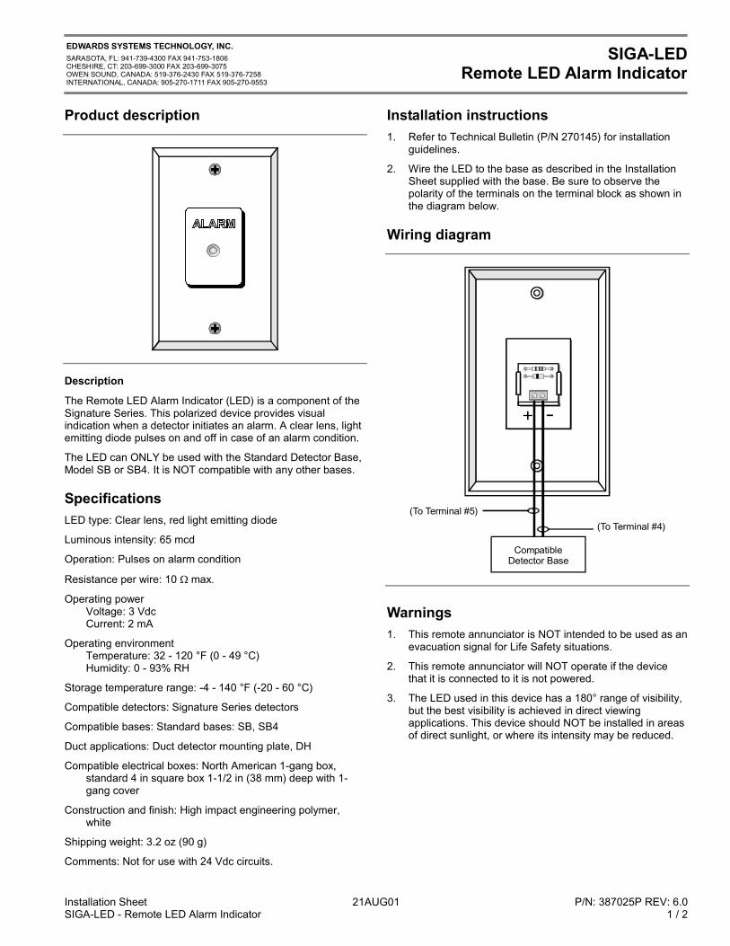
Installation Sheet 21AUG01 P/N: 387025P REV: 6.0SIGA-LED - Remote LED Alarm Indicator 1 / 2
EDWARDS SYSTEMS TECHNOLOGY, INC.SARASOTA, FL: 941-739-4300 FAX 941-753-1806CHESHIRE, CT: 203-699-3000 FAX 203-699-3075OWEN SOUND, CANADA: 519-376-2430 FAX 519-376-7258INTERNATIONAL, CANADA: 905-270-1711 FAX 905-270-9553
SIGA-LEDRemote LED Alarm Indicator
Product description
Description
The Remote LED Alarm Indicator (LED) is a component of theSignature Series. This polarized device provides visualindication when a detector initiates an alarm. A clear lens, lightemitting diode pulses on and off in case of an alarm condition.
The LED can ONLY be used with the Standard Detector Base,Model SB or SB4. It is NOT compatible with any other bases.
SpecificationsLED type: Clear lens, red light emitting diode
Luminous intensity: 65 mcd
Operation: Pulses on alarm condition
Resistance per wire: 10 max.
Operating powerVoltage: 3 VdcCurrent: 2 mA
Operating environmentTemperature: 32 - 120 °F (0 - 49 °C)Humidity: 0 - 93% RH
Storage temperature range: -4 - 140 °F (-20 - 60 °C)
Compatible detectors: Signature Series detectors
Compatible bases: Standard bases: SB, SB4
Duct applications: Duct detector mounting plate, DH
Compatible electrical boxes: North American 1-gang box,standard 4 in square box 1-1/2 in (38 mm) deep with 1-gang cover
Construction and finish: High impact engineering polymer,white
Shipping weight: 3.2 oz (90 g)
Comments: Not for use with 24 Vdc circuits.
Installation instructions1. Refer to Technical Bulletin (P/N 270145) for installation
guidelines.
2. Wire the LED to the base as described in the InstallationSheet supplied with the base. Be sure to observe thepolarity of the terminals on the terminal block as shown inthe diagram below.
Wiring diagram
(To Terminal #5)(To Terminal #4)
CompatibleDetector Base
Warnings1. This remote annunciator is NOT intended to be used as an
evacuation signal for Life Safety situations.
2. This remote annunciator will NOT operate if the devicethat it is connected to it is not powered.
3. The LED used in this device has a 180° range of visibility,but the best visibility is achieved in direct viewingapplications. This device should NOT be installed in areasof direct sunlight, or where its intensity may be reduced.
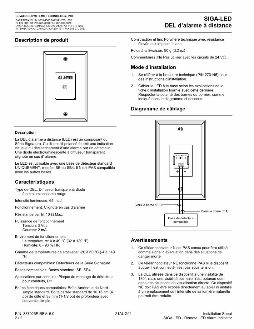
P/N: 387025P REV: 6.0 21AUG01 Installation Sheet2 / 2 SIGA-LED - Remote LED Alarm Indicator
EDWARDS SYSTEMS TECHNOLOGY, INC.SARASOTA, FL: 941-739-4300 FAX 941-753-1806CHESHIRE, CT: 203-699-3000 FAX 203-699-3075OWEN SOUND, CANADA: 519-376-2430 FAX 519-376-7258INTERNATIONAL, CANADA: 905-270-1711 FAX 905-270-9553
SIGA-LEDDEL d’alarme à distance
Description de produit
Description
La DEL d’alarme à distance (LED) est un composant duSérie Signature. Ce dispositif polarisé fournit une indicationvisuelle du déclenchement d’une alarme par un détecteur.Une diode électroluminescente à diffuseur transparentclignote en cas d' alarme.
Le LED est utilisable avec une base de détecteur standardUNIQUEMENT, modèle SB ou SB4. Il N’est PAS compatibleavec les autres bases.
CaractéristiquesType de DEL: Diffuseur transparent, diode
électroluminescente rouge
Intensité lumineuse: 65 mcd
Fonctionnement: Clignote en cas d’alarme
Résistance par fil: 10 Max.
Puissance de fonctionnementTension: 3 VdcCourant: 2 mA
Enviroment de fonctionnementLa température: 0 à 49 °C (32 à 120 °F)Humidité: 0 - 93 % HR
Gamme de températures de stockage: -20 à 60 °C (-4 à 140°F)
Détecteurs compatibles: Détecteurs de la Série Signature
Bases compatibles: Bases standard: SB, SB4
Applications sur conduits: Plaque de montage de détecteurpour conduits, DH
Boîtes électriques compatibles: Boîte Amérique du Nordsimple standard. Boîte carrée standard de 10,16 cm (4po) de côté et 38 mm (1-1/2 po) de profondeur aveccouvercle simple.
Construction et fini: Polymère technique avec résistanceélevée aux impacts, blanc
Poids à la livraison: 90 g (3,2 oz)
Commentaires :Ne Pas utiliser avec les circuits de 24 Vcc.
Mode d’installation1. Se référer à la brochure technique (P/N 270145) pour
des instructions d’installation.
2. Câbler le LED à la base selon les explications de lafiche d’installation fournie avec cette dernière.Respecter la polarité des bornes du bornier, commeindiqué dans le diagramme ci-dessous.
Diagramme de câblage
( )°Vers la borne n 5
( )°Vers la borne n 4
Base de détecteurcompatible
Avertissements1. Ce téléannonciateur N’est PAS conçu pour être utilisé
comme signal d’évacuation dans des situations dedanger mortel.
2. Ce téléannonciateur NE fonctionne PAS si le dispositifauquel il est connecté n’est pas sous tension.
3. La DEL utilisée dans ce dispositif a une visibilité de180°, mais une visibilité optimale n’est obtenue quedans des situations de visualisation directe. Ce dispositifNE doit PAS être exposé directement au soleil ni installéà un emplacement où l intensité de sa lumière naturellepourrait être réduite.
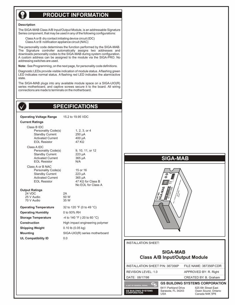
PRODUCT INFORMATION
SIGA-MAB
SPECIFICATIONS
DATE: 08/17/98
INSTALLATION SHEET:
INSTALLATION SHEET P/N: 387356P FILE NAME: 387356P.CDR
REVISION LEVEL: 1.0
CREATED BY: B. Graham
APPROVED BY: R. Right
GS BUILDING SYSTEMSCORPORATION
A UNIT OF GENERAL SIGNAL
SIGA-MABClass A/B Input/Output Module
Operating Voltage Range 15.2 to 19.95 VDC
Output Ratings24 VDC 2A25 V Audio 50 W70 V Audio 35 W
Operating Temperature 32 to 120 °F (0 to 49 °C)
Operating Humidity 0 to 93% RH
Storage Temperature -4 to 140 °F (-20 to 60 °C)
Construction High impact engineering polymer
Shipping Weight 0.10 lb (0.05 kg)
Mounting SIGA-UIO(R) series motherboard
UL Compatibility ID 0.0
Current Ratings
Class B IDCPersonality Code(s) 1, 2, 3, or 4Standby Current 250 µAActivated Current 400 µAEOL Resistor 47 KΩ
Class A IDCPersonality Code(s) 9, 10, 11, or 12Standby Current 223 µAActivated Current 365 µAEOL Resistor N/A
Class A or B NACPersonality Code(s) 15 or 16Standby Current 223 µAActivated Current 365 µAEOL Resistor 47 KΩ for Class B
No EOL for Class A
CA
T N
O.
JP2JP1
SIG
A-M
AB
4733
8735
6E
DW
AR
DS
SY
ST
EM
S T
EC
HN
OLO
GY
ALL CIRCUITS POWER LIMITED
387356P
9810
Description
The SIGA-MAB Class A/B Input/Output Module, is an addressable Signature Series component, that may be used in any of the following configurations:
Class A or B dry contact initiating device circuit (IDC)Class A or B notification appliance circuit (NAC)
Note: See Programming, on the next page, for personality code definitions.
Diagnostic LEDs provide visible indication of module status. A flashing green LED indicates normal status. A flashing red LED indicates the alarm/active state.
The SIGA-MAB plugs into any available module space on a SIGA-UIO(R) series motherboard, and captive screws secure it to the board. All wiring connections are made to terminals on the motherboard.
The personality code determines the function performed by the SIGA-MAB. The Signature controller automatically assigns two addresses and downloads personality codes to the SIGA-MAB during system configuration. A custom address can be assigned to the module via the SIGA-PRO. No addressing switches are used.
GS BUILDING SYSTEMSCORPORATION
A UNIT OF GENERAL SIGNALGS BUILDING SYSTEMS CORPORATION6411 Parkland DriveSarasota, FL 34243USA
625 6th Street EastOwen Sound, OntarioCanada N4K 5P8
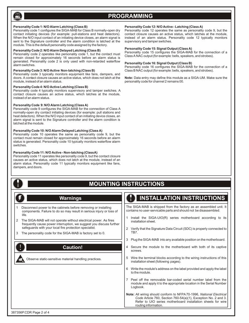
PROGRAMMING
Personality Code 1: N/O Alarm Latching (Class B)Personality code 1 configures the SIGA-MAB for Class B normally-open dry contact initiating devices (for example: pull-stations and heat detectors). When the N/O input contact of an initiating device closes, an alarm signal is sent to the Signature controller and the alarm condition is latched at the module. This is the default personality code assigned by the factory.
Personality Code 2: N/O Alarm Delayed Latching (Class B)Personality code 2 operates like personality code 1, but the contact must remain closed for approximately 16 seconds before an alarm status is generated. Personality code 2 is only used with non-retarded waterflow alarm switches.
Personality Code 3: N/O Active Non-latching (Class B)
Personality Code 4: N/O Active Latching (Class B)
Personality code 3 typically monitors equipment like fans, dampers, and doors. A contact closure causes an active status, which does not latch at the module, instead of an alarm status.
Personality code 4 typically monitors supervisory and tamper switches. A contact closure causes an active status, which latches at the module, instead of an alarm status.
Personality Code 9: N/O Alarm Latching (Class A)Personality code 9 configures the SIGA-MAB for the connection of Class A normally-open dry contact initiating devices (for example: pull stations and heat detectors). When the N/O input contact of an initiating device closes, an alarm signal is sent to the Signature controller and the alarm condition is latched at the module.
Personality Code 10: N/O Alarm Delayed Latching (Class A)Personality code 10 operates the same as personality code 9, but the contact must remain closed for approximately 16 seconds before an alarm status is generated. Personality code 10 typically monitors waterflow alarm switches.
Personality Code 11: N/O Active - Non-latching (Class A)Personality code 11 operates like personality code 9, but the contact closure causes an active status, which does not latch at the module, instead of an alarm status. Personality code 11 typically monitors equipment like fans, dampers, and doors.
Personality Code 12: N/O Active - Latching (Class A)Personality code 12 operates the same as personality code 9, but the contact closure causes an active status, which latches at the module, instead of an alarm status. Personality code 12 typically monitors supervisory and tamper switches.
Personality Code 15: Signal Output (Class A)Personality code 15 configures the SIGA-MAB for the connection of a Class A NAC output (for example: bells, speakers, and strobes).
Personality Code 16: Signal Output (Class B)Personality code 16 configures the SIGA-MAB for the connection of a Class B NAC output (for example: bells, speakers, and strobes).
Note: Data entry may define this module as a SIGA-UM. Make sure the personality code for channel 2 remains 00.
?
MOUNTING INSTRUCTIONS
387356P.CDR Page 2 of 4
1 Disconnect power to the cabinets before removing or installing components. Failure to do so may result in serious injury or loss of life.
2 The SIGA-MAB will not operate without electrical power. As fires frequently cause power interruption, we suggest you discuss further safeguards with your local fire protection specialist.
3 The personality code for the SIGA-MAB is factory set to 0.
Warnings
! Caution!
Observe static-sensitive material handling practices.
INSTALLATION INSTRUCTIONS
The SIGA-MAB is shipped from the factory as an assembled unit. It contains no user-servicable parts and should not be disassembled.
1 Install the SIGA-UIO(R) series motherboard according to its installation sheet.
2 Verify that the Signature Data Circuit (SDC) is properly connected to TB7.
3 Plug the SIGA-MAB into any available position on the motherboard.
4 Secure the module to the motherboard with both of its captive screws.
5 Wire the terminal blocks according to the wiring instructions of this installation sheet (following pages).
6 Write the module's address on the label provided and apply the label to the module.
7 Peel off the removable bar-coded serial number label from the module and apply it to the appropriate location in the Serial Number Logbook.
Note: All wiring should conform to NFPA 70-1996, National Electrical Code Article 760, Section 760-54(a)(1), Exception No. 2 and 3. Refer to UIO series motherboard installation sheets for wire routing information.
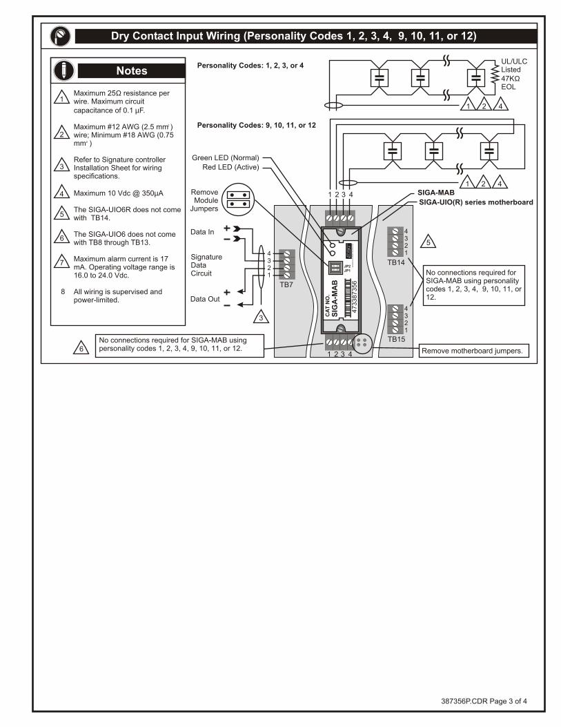
4321
4321
TB14
TB15
SIGA-MAB
Personality Codes: 1, 2, 3, or 4
Personality Codes: 9, 10, 11, or 12
No connections required for SIGA-MAB using personality codes 1, 2, 3, 4, 9, 10, 11, or 12.
No connections required for SIGA-MAB using personality codes 1, 2, 3, 4, 9, 10, 11, or 12.
1 2 3 4
5
6 Remove motherboard jumpers.
SIGA-UIO(R) series motherboard
CA
T N
O.
JP2JP1
SIG
A-M
AB
47
33
87
35
6E
DW
AR
DS
SY
ST
EM
S T
EC
HN
OL
OG
Y
Dry Contact Input Wiring (Personality Codes 1, 2, 3, 4, 9, 10, 11, or 12)
1 2 4
1 2 3 4
3
1
2
8
4
5
6
7
Maximum 25Ω resistance per wire. Maximum circuit capacitance of 0.1 µF.
2Maximum #12 AWG (2.5 mm ) wire; Minimum #18 AWG (0.75
2mm )
Refer to Signature controller Installation Sheet for wiring specifications.
Maximum 10 Vdc @ 350µA
The SIGA-UIO6R does not come with TB14.
The SIGA-UIO6 does not come with TB8 through TB13.
Maximum alarm current is 17 mA. Operating voltage range is 16.0 to 24.0 Vdc. All wiring is supervised and power-limited.
NotesUL/ULCListed47KΩEOL
1 2 4
TB7
Green LED (Normal)
Red LED (Active)
Data Out
SignatureDataCircuit
Data In
RemoveModule
Jumpers
3
4321
387356P.CDR Page 3 of 4
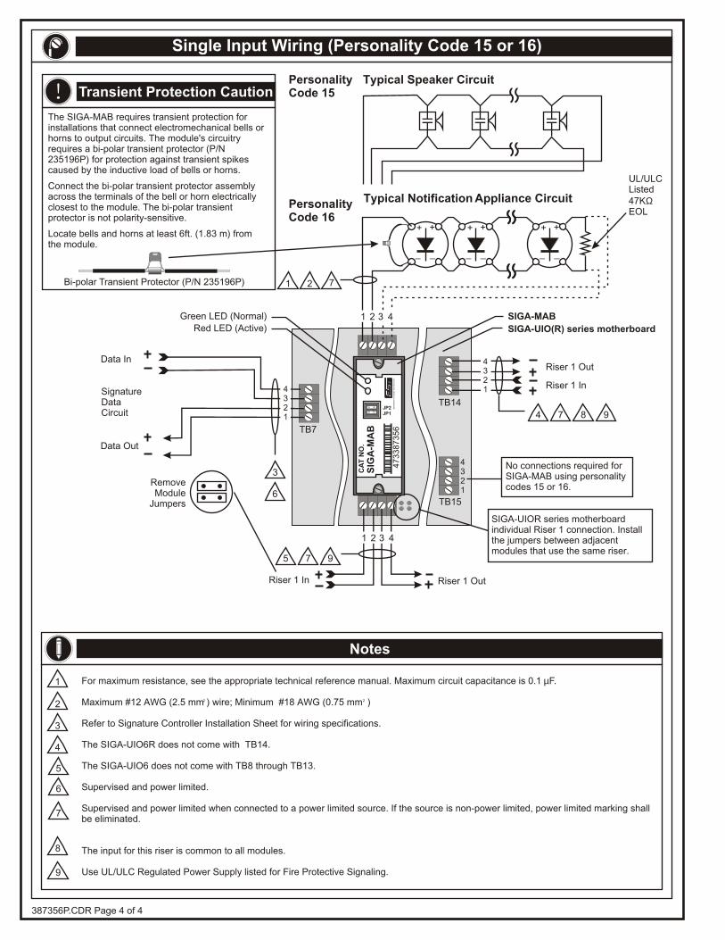
+ +
_ _
+ +
_ _
+ +
_ _
Riser 1 Out
Riser 1 Out
4321
TB14
TB15
No connections required for SIGA-MAB using personality codes 15 or 16.
1 2
Riser 1 In
Riser 1 In
Single Input Wiring (Personality Code 15 or 16)
UL/ULCListed47KΩEOL
Typical Notification Appliance Circuit
Typical Speaker Circuit
The SIGA-MAB requires transient protection for installations that connect electromechanical bells or horns to output circuits. The module's circuitry requires a bi-polar transient protector (P/N 235196P) for protection against transient spikes caused by the inductive load of bells or horns.
Connect the bi-polar transient protector assembly across the terminals of the bell or horn electrically closest to the module. The bi-polar transient protector is not polarity-sensitive.
Locate bells and horns at least 6ft. (1.83 m) from the module.
Bi-polar Transient Protector (P/N 235196P)
Transient Protection Caution
4321
1 2 3 4
PersonalityCode 15
PersonalityCode 16
!
3
1
2
4
5
6
7
6
8
9
4 97 8
7
975
For maximum resistance, see the appropriate technical reference manual. Maximum circuit capacitance is 0.1 µF.
2 2Maximum #12 AWG (2.5 mm ) wire; Minimum #18 AWG (0.75 mm )
Refer to Signature Controller Installation Sheet for wiring specifications.
The SIGA-UIO6R does not come with TB14.
The SIGA-UIO6 does not come with TB8 through TB13.
Supervised and power limited.
Supervised and power limited when connected to a power limited source. If the source is non-power limited, power limited marking shall be eliminated.
The input for this riser is common to all modules.
Use UL/ULC Regulated Power Supply listed for Fire Protective Signaling.
Notes
SIGA-UIO(R) series motherboard
SIGA-MAB
CA
T N
O.
JP2JP1
SIG
A-M
AB
47
33
87
35
6E
DW
AR
DS
SY
ST
EM
S T
EC
HN
OL
OG
Y
387356P.CDR Page 4 of 4
1 2 3 4
SIGA-UIOR series motherboard individual Riser 1 connection. Install the jumpers between adjacentmodules that use the same riser.
TB7
Green LED (Normal)
Red LED (Active)
Data Out
SignatureDataCircuit
Data In
RemoveModule
Jumpers
3
4321
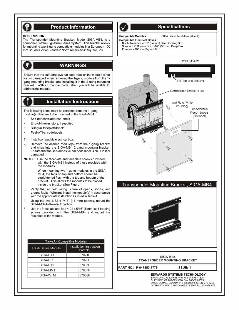
Product Information
Installation Instructions
WARNINGS
Specifications
EDWARDS SYSTEMS TECHNOLOGYSARASOTA , FL 800-655-4497 Fax. 941-753-1806CHESHIRE, CT 203-699-3000 Fax. 203-699-3075OWEN SOUND, CANADA 519-376-2430 Fax. 519-376-7258INTERNATIONAL: CANADA 905-678-6767 Fax. 905-678-9791
SIGA-MB4TRANSPONDER MOUNTING BRACKET
PART NO.: P-047550-1775 ISSUE: 1
SIGA Series Module
Table A - Compatible Modules
Installation Instruction Part No.
SIGA-CT1 387021P
387023P
387037P
387057P
387058P
SIGA-CR
SIGA-CT2
SIGA-MM1
SIGA-WTM
DESCRIPTIONThe Transponder Mounting Bracket, Model SIGA-MB4, is a component of the Signature Series System. This bracket allows for mounting two 1-gang compatible modules in a European 100 mm Square Box or Standard North American 4" Square Box.
Ensure that the self-adhesive bar code label on the module is not lost or damaged when removing the 1-gang module from the 1-gang mounting bracket and installing it in the 2-gang mounting bracket. Without the bar code label, you will be unable to address the module.
The following items must be retained from the 1-gang module(s) that are to be mounted in the SIGA-MB4:
• Self-adhesive address labels
• End-of-line resistors, if supplied
• Bilingual faceplate labels
• Peel-off bar code labels
1) Install compatible electrical box.
2) Remove the desired module(s) from the 1-gang bracket and snap into the SIGA-MB4 2-gang mounting bracket. Ensure that the self-adhesive bar code label is NOT lost or damaged.
NOTES: Use the faceplate and faceplate screws provided with the SIGA-MB4 instead of those provided with the modules.
When mounting two 1-gang modules in the SIGA-MB4, the tabs on top and bottom should be straightened flush with the top and bottom of the bracket. This allows the modules to be placed inside the bracket (See Figure).
3) Verify that all field wiring is free of opens, shorts, and ground faults. Wire and install the module(s) in accordance with the appropriate instruction as listed in Table A.
4) Using the two 6-32 x 7/16" (11 mm) screws, mount the SIGA-MB4 to the electrical box.
5) Use the faceplate and four 4-24 x 5/16" (8 mm) self-tapping screws provided with the SIGA-MB4 and mount the faceplate to the module.
Compatible Modules SIGA Series Modules (Table A)
Compatible Electrical BoxesNorth American 2-1/2" (64 mm) Deep 2-Gang BoxStandard 4" Square Box 1-1/2" (38 mm) Deep BoxEuropean 100 mm Square Box
Transponder Mounting Bracket, SIGA-MB4

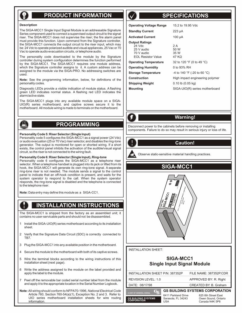
CA
T N
O.
SIG
A-M
CC
1
4733
8735
2E
DW
AR
DS
SY
ST
EM
S T
EC
HN
OLO
GY
ALL CIRCUITS POWER LIMITED
387352P
9810
PRODUCT INFORMATION
SIGA-MCC1
SPECIFICATIONS
INSTALLATION INSTRUCTIONS
DATE: 08/17/98
INSTALLATION SHEET:
INSTALLATION SHEET P/N: 387352P FILE NAME: 387352P.CDR
REVISION LEVEL: 1.0
CREATED BY: B. Graham
APPROVED BY: R. Right
SIGA-MCC1Single Input Signal Module
Operating Voltage Range 15.2 to 19.95 Vdc
Standby Current 223 µΑ
Activated Current 100 µA
Output Ratings24 Vdc 2 A25 V audio 50 W70 V audio 35 WEOL Resistor Value 47 KΩ
Operating Temperature 32 to 120 °F (0 to 49 °C)
Operating Humidity 0 to 93% RH
Storage Temperature -4 to 140 °F (-20 to 60 °C)
Construction High impact engineering polymer
Shipping Weight 0.10 lb (0.05 kg)
Mounting SIGA-UIO(R) series motherboard
The SIGA-MCC1 is shipped from the factory as an assembled unit; it contains no user-servicable parts and should not be disassembled.
1 Install the SIGA-UIO(R) series motherboard according to its installation sheet.
2 Verify that the Signature Data Circuit (SDC) is correctly connected to TB7.
3 Plug the SIGA-MCC1 into any available position in the motherboard.
4 Secure the module to the motherboard with both of its captive screws.
5 Wire the terminal blocks according to the wiring instructions of this installation sheet (next page).
6 Write the address assigned to the module on the label provided and apply the label to the module.
7 Peel off the removable bar coded serial number label from the module and apply it to the appropriate location in the Serial Number Logbook.
Note: All wiring should conform to NFPA 70-1996, National Electrical Code Article 760, Section 760-54(a)(1), Exception No. 2 and 3. Refer to UIO series motherboard installation sheets for wire routing information.
Description
The SIGA-MCC1 Single Input Signal Module is an addressable Signature Series component used to connect a supervised output circuit to the signal riser. The SIGA-MCC1 does not supervise the riser; the fire alarm panel must provide this function. Upon command from the Signature controller, the SIGA-MCC1 connects the output circuit to the riser input, which may be: 24 Vdc to operate polarized audible and visual appliances, 25 Vac or 70 Vac to operate audio evacuation circuits, or telephone audio.
Note: See the programming information, below, for definitions of the personality codes.
Diagnostic LEDs provide a visible indication of module status. A flashing green LED indicates normal status. A flashing red LED indicates the alarm/active state.
The SIGA-MCC1 plugs into any available module space on a SIGA-UIO(R) series motherboard, and captive screws secure it to the motherboard. All module wiring is made to terminals on the motherboard.
The personality code downloaded to the module by the Signature controller during system configuration determines the function performed by the SIGA-MCC1. The SIGA-MCC1 requires one module address, which the Signature controller assigns to it. A custom address can be assigned to the module via the SIGA-PRO. No addressing switches are used.
Personality Code 5: Riser Selector (Single Input)Personality code 5 configures the SIGA-MCC1 as a signal power (24 Vdc) or audio evacuation (25 or 70 Vac) riser selector, and disables the ring-tone generator. The output is monitored for open or shorted wiring. If a short exists, the control panel inhibits the activation of the audible/visual signal circuit, so the riser is not connected to the wiring fault.
Personality Code 6: Riser Selector (Single Input), Ring-tonePersonality code 6 configures the SIGA-MCC1 as a telephone riser selector. When a telephone handset is plugged into its jack or lifted from its hook, the SIGA-MCC1 will generate its own ring-tone signal. A separate ring-tone riser is not needed. The module sends a signal to the control panel to indicate that an off-hook condition is present, and waits for the system operator to respond to the call. When the system operator responds, the ring-tone signal is disabled and the telephone is connected to the telephone riser.
Note: Data entry may define this module as a SIGA-CC1.
? PROGRAMMING Disconnect power to the cabinets before removing or installing components. Failure to do so may result in serious injury or loss of life.
Warning!
! Caution!
Observe static-sensitive material handling practices.
GS BUILDING SYSTEMSCORPORATION
A UNIT OF GENERAL SIGNALGS BUILDING SYSTEMS CORPORATION6411 Parkland DriveSarasota, FL 34243USA
625 6th Street EastOwen Sound, OntarioCanada N4K 5P8
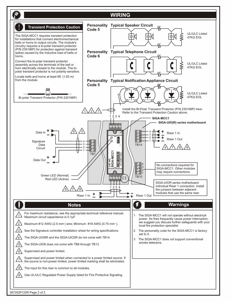
Riser 1 Out
Riser 1 OutRiser 1 In
4321
TB14
TB15Green LED (Normal)
SIGA-MCC1
No connections required for SIGA-MCC1. Other modules may require connections.
1 2
Riser 1 In
Red LED (Active)
CA
T N
O.
SIG
A-M
CC
1
47
33
87
35
2E
DW
AR
DS
SY
ST
EM
S T
EC
HN
OL
OG
Y
WIRING
UL/ULC Listed47KΩ EOL
UL/ULC Listed47KΩ EOL
UL/ULC Listed47KΩ EOL
Typical Notification Appliance Circuit
Typical Telephone Circuit
Typical Speaker Circuit
Bi-polar Transient Protector (P/N 235196P)
Transient Protection Caution
4321
1 2 3 4
PersonalityCode 5
PersonalityCode 5
PersonalityCode 6
!
1 The SIGA-MCC1 will not operate without electrical power. As fires frequently cause power interruption, we suggest you discuss further safeguards with your local fire protection specialist.
2 The personality code for the SIGA-MCC1 is factory set to 5.
3 The SIGA-MCC1 does not support conventional smoke detectors.
Warnings
SIGA-UIOR series motherboard individual Riser 1 connection. Install the jumpers between adjacentmodules that use the same riser.
SIGA-UIO(R) series motherboard
Install the Bi-Polar Transient Protector (P/N 235196P) here. Refer to the Transient Protection Caution above.
387352P.CDR Page 2 of 2
The SIGA-MCC1 requires transient protection for installations that connect electromechanical bells or horns to output circuits. The module's circuitry requires a bi-polar transient protector (P/N 235196P) for protection against transient spikes caused by the inductive load of bells or horns.
Connect the bi-polar transient protector assembly across the terminals of the bell or horn electrically closest to the module. The bi-polar transient protector is not polarity-sensitive.
Locate bells and horns at least 6ft. (1.83 m) from the module.
3
1
2
4
5
6
7
Data Out
SignatureData
Circuit
TB7
Data In
4321
36
8
7
For maximum resistance, see the appropriate technical reference manual. Maximum circuit capacitance is 0.1µF.
Supervised and power limited when connected to a power limited source. If the source is non-power limited, power limited marking shall be eliminated.
The input for this riser is common to all modules.
Use UL/ULC Regulated Power Supply listed for Fire Protective Signaling.
2 2Maximum #12 AWG (2.5 mm ) wire; Minimum #18 AWG (0.75 mm ).
See the Signature controller installation sheet for wiring specifications.
The SIGA-UIO6R and the SIGA-UIO2R do not come with TB14.
The SIGA-UIO6 does not come with TB8 through TB13.
Supervised and power limited.
Notes
+ +
_ _
+ +
_ _
+ +
_ _
1 2 3 4
9
4 97 8
975
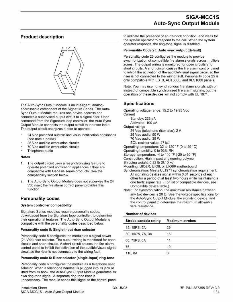
Installation Sheet 30JUN03 P/N: 387355 REV: 3.0 SIGA-MCC1S - Auto-Sync Output Module 1 / 4
SIGA-MCC1S
Auto-Sync Output Module Product description
The Auto-Sync Output Module is an intelligent, analog-addressable component of the Signature Series. The Auto-Sync Output Module requires one device address and connects a supervised output circuit to a signal riser. Upon command from the Signature loop controller, the Auto-Sync Output Module connects the output circuit to the riser input. The output circuit energizes a riser to operate:
• 24 Vdc polarized audible and visual notification appliances (see note 1 below)
• 25 Vac audible evacuation circuits • 70 Vac audible evacuation circuits • Telephone audio
Notes
1. The output circuit uses a resynchronizing feature to operate polarized notification appliances if they are compatible with Genesis series products. See the compatibility section below.
2. The Auto-Sync Output Module does not supervise the 24 Vdc riser; the fire alarm control panel provides this function.
Personality codes System controller compatibility
Signature Series modules require personality codes, downloaded from the Signature loop controller, to determine their operational features. The Auto-Sync Output Module is compatible with the personality codes described below.
Personality code 5: Single-input riser selector
Personality code 5 configures the module as a signal power (24 Vdc) riser selector. The output wiring is monitored for open circuits and short circuits. A short circuit causes the fire alarm control panel to inhibit the activation of the audible/visual signal circuit so the riser is not connected to the wiring fault.
Personality code 6: Riser selector (single-input) ring-tone
Personality code 6 configures the module as a telephone riser selector. When a telephone handset is plugged into its jack or lifted from its hook, the Auto-Sync Output Module generates its own ring-tone signal. A separate ring-tone riser is unnecessary. The module sends this signal to the control panel
to indicate the presence of an off-hook condition, and waits for the system operator to respond to the call. When the system operator responds, the ring-tone signal is disabled.
Personality Code 25: Auto sync output (default)
Personality code 25 configures the module to provide synchronization of compatible fire alarm signals across multiple zones. The output wiring is monitored for open circuits and short circuits. A short circuit causes the fire alarm control panel to inhibit the activation of the audible/visual signal circuit so the riser is not connected to the wiring fault. Personality code 25 is only compatible with EST3, ADT3000, and XLS1000 panels.
Note: You may use nonsynchronous fire alarm signals with or instead of compatible synchronized fire alarm signals, but the operation of these devices will not comply with UL 1971.
Specifications Operating voltage range: 15.2 to 19.95 Vdc Current
Standby: 223 µA Activated: 100 µA
Output ratings 24 Vdc (telephone riser also): 2 A 25 Vac audio: 50 W 70 Vac audio: 35 W EOL resistor value: 47 kΩ
Operating temperature: 32 to 120 °F (0 to 49 °C) Operating humidity: 0 to 93% RH Storage temperature: -4 to 140 °F (-20 to 60 °F) Construction: High impact engineering polymer Shipping weight: 0.22 lb (0.10 kg) Mounting: UIO2R, UIO6, or UIO6R motherboard Synchronization: Meets UL1971 synchronization requirement.
All signaling devices signal within 0.01 seconds of each other for a period of at least two hours while maintaining a one hertz signal rate. (For list of compatible devices, see Compatible device table.)
Note: For synchronization, the maximum resistance between any two devices is 20 Ω. See the voltage specifications for the Auto-Sync Output Module, the signaling device, and the control panel to determine the maximum allowable wire resistance.
Number of devices
Strobe candela rating Maximum strobes
15, 15PS, 5A 29
30, 15/75, 7A, 3A 16
60, 75PS, 6A 11
75 10
110, 8A 8
P/N: 387355 REV: 3.0 30JUN03 Installation Sheet 2 / 4 SIGA-MCC1S - Auto-Sync Output Module
Installation instructions To install the module:
1. Install the Signature motherboard (UIO2R, UIO6, or UIO6R). See the motherboard installation sheet for more information.
2. Plug the module into any available position on the Signature motherboard.
3. Secure the module to the motherboard with the two captive screws on the module.
4. Wire the module according to the instructions in the wiring diagram.
5. Write the address assigned to the module on the label and apply it to the module.
6. Remove the bar-coded serial number label from the module and apply it to the appropriate location in the serial number log book.
Notes
• The factory ships the Auto-Sync Output Module as an assembled unit; it contains no user-servicable parts and should not be disassembled.
• Install in accordance with applicable requirements of the latest editions of the NFPA codes and standards, the Canadian Electrical Code (Part 1, Section 32), and the authority having jurisdiction.
Warnings
• Disconnect power to cabinets before installing or removing components. Failure to do so may result in serious injury or loss of life. Dangerous voltages may be present at the terminals even when power is shut off!
• This module will not operate without electrical power. As fires frequently cause power interruption, we suggest you discuss further safeguards with your local fire protection specialist.
• This module does not support conventional smoke detectors.
Caution: Observe static sensitive material handling practices.
LEDs Diagnostic LEDs provide visible indication of the status of the module.
Status LED indicator
Normal/Trouble Green LED flashes
Short/Active Red LED flashes
Transient protection caution The Auto-Sync Output Module requires transient protection for installations that connect electromechanical bells or horns to output circuits. The module's circuitry requires a bipolar transient protector (P/N 235196P) for protection against transient spikes caused by the inductive load of bells or horns.
Connect the bipolar transient protector assembly across the terminals of the bell or horn electrically closest to the module. The bipolar transient protector is not polarity-sensitive.
Locate bells and horns at least 6 ft (1.83 m) from the module.
Bipolar Transient Protector (P/N 235196P)
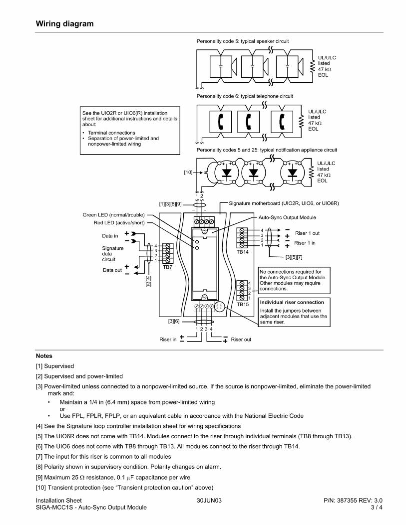
Installation Sheet 30JUN03 P/N: 387355 REV: 3.0 SIGA-MCC1S - Auto-Sync Output Module 3 / 4
Wiring diagram
4321
TB14
TB15
1 2 3 4
Individual riser connectionInstall the jumpers between adjacent modules that use the same riser.
1 2
TB7
Green LED (normal/trouble)Red LED (active/short)
Data out
Signaturedatacircuit
Data in
4321
No connections required for the Auto-Sync Output Module. Other modules may require connections.
Auto-Sync Output Module
+ +
_ _
+ +
_ _
+ +
_ _
Personality codes 5 and 25: typical notification appliance circuit
Riser 1 out
Riser 1 in
4321
Personality code 6: typical telephone circuit
Personality code 5: typical speaker circuit
Riser out
+_Signature motherboard (UIO2R, UIO6, or UIO6R)
UL/ULClisted47 kEOL
Ω
Riser in
[1][3][8][9]
[3][5][7]
[3][6]
[4][2]
See the UIO2R or UIO6(R) installation sheet for additional instructions and details about:
• Terminal connections• Separation of power-limited and
nonpower-limited wiring
UL/ULClisted47 kEOL
Ω
UL/ULClisted47 kEOL
Ω[10]
Notes [1] Supervised
[2] Supervised and power-limited
[3] Power-limited unless connected to a nonpower-limited source. If the source is nonpower-limited, eliminate the power-limited mark and: • Maintain a 1/4 in (6.4 mm) space from power-limited wiring or • Use FPL, FPLR, FPLP, or an equivalent cable in accordance with the National Electric Code
[4] See the Signature loop controller installation sheet for wiring specifications
[5] The UIO6R does not come with TB14. Modules connect to the riser through individual terminals (TB8 through TB13).
[6] The UIO6 does not come with TB8 through TB13. All modules connect to the riser through TB14.
[7] The input for this riser is common to all modules
[8] Polarity shown in supervisory condition. Polarity changes on alarm.
[9] Maximum 25 Ω resistance, 0.1 µF capacitance per wire
[10] Transient protection (see “Transient protection caution” above)
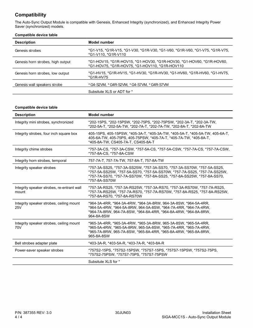
P/N: 387355 REV: 3.0 30JUN03 Installation Sheet 4 / 4 SIGA-MCC1S - Auto-Sync Output Module
Compatibility The Auto-Sync Output Module is compatible with Genesis, Enhanced Integrity (synchronized), and Enhanced Integrity Power Saver (synchronized) models.
Compatible device table
Description Model number
Genesis strobes *G1-V15, *G1R-V15, *G1-V30, *G1R-V30, *G1-V60, *G1R-V60, *G1-V75, *G1R-V75, *G1-V110, *G1R-V110
Genesis horn strobes, high output *G1-HOV15, *G1R-HOV15, *G1-HOV30, *G1R-HOV30, *G1-HOV60, *G1R-HOV60, *G1-HOV75, *G1R-HOV75, *G1-HOV110, *G1R-HOV110
Genesis horn strobes, low output *G1-HV15, *G1R-HV15, *G1-HV30, *G1R-HV30, *G1-HV60, *G1R-HV60, *G1-HV75, *G1R-HV75
Genesis wall speakers strobe *G4-S2VM, *G4R-S2VM, *G4-S7VM, *G4R-S7VM
Subsitute XLS or ADT for *
Compatible device table
Description Model number
Integrity mini strobes, synchronized *202-15PS, *202-15PSW, *202-75PS, *202-75PSW, *202-3A-T, *202-3A-TW, *202-5A-T, *202-5A-TW, *202-7A-T, *202-7A-TW, *202-8A-T, *202-8A-TW
Integrity strobes, four inch square box 405-15PS, 405-15PSW, *405-3A-T, *405-3A-TW, *405-5A-T, *405-5A-TW, 405-6A-T, 405-6A-TW, 405-75PS, 405-75PSW, *405-7A-T, *405-7A-TW, *405-8A-T, *405-8A-TW, CS405-7A-T, CS405-8A-T
Integrity chime strobes *757-3A-CS, *757-3A-CSW, *757-5A-CS, *757-5A-CSW, *757-7A-CS, *757-7A-CSW, *757-8A-CS, *757-8A-CSW
Integrity horn strobes, temporal 757-7A-T, 757-7A-TW, 757-8A-T, 757-8A-TW
Integrity speaker strobes *757-3A-SS25, *757-3A-SS25W, *757-3A-SS70, *757-3A-SS70W, *757-5A-SS25, *757-5A-SS25W, *757-5A-SS70, *757-5A-SS70W, *757-7A-SS25, *757-7A-SS25W, *757-7A-SS70, *757-7A-SS70W, *757-8A-SS25, *757-8A-SS25W, *757-8A-SS70, *757-8A-SS70W
Integrity speaker strobes, re-entrant wall mount
*757-3A-RS25, *757-3A-RS25W, *757-3A-RS70, *757-3A-RS70W, *757-7A-RS25, *757-7A-RS25W, *757-7A-RS70, *757-7A-RS70W, *757-8A-RS25, *757-8A-RS25W, *757-8A-RS70, *757-8A-RS70W
Integrity speaker strobes, ceiling mount 25V
*964-3A-4RR, *964-3A-4RW, *964-3A-8RW, 964-3A-8SW, *964-5A-4RR, *964-5A-4RW, *964-5A-8RW, 964-5A-8SW, *964-7A-4RR, *964-7A-4RW, *964-7A-8RW, 964-7A-8SW, *964-8A-4RR, *964-8A-4RW, *964-8A-8RW, 964-8A-8SW
Integrity speaker strobes, ceiling mount 70V
*965-3A-4RR, *965-3A-4RW, *965-3A-8RW, 965-3A-8SW, *965-5A-4RR, *965-5A-4RW, *965-5A-8RW, 965-5A-8SW, *965-7A-4RR, *965-7A-4RW, *965-7A-8RW, 965-7A-8SW, *965-8A-4RR, *965-8A-4RW, *965-8A-8RW, 965-8A-8SW
Bell strobes adapter plate *403-3A-R, *403-5A-R, *403-7A-R, *403-8A-R
Power-saver speaker strobes *757S2-15PS, *757S2-15PSW, *757S7-15PS, *757S7-15PSW, *757S2-75PS, *757S2-75PSW, *757S7-75PS, *757S7-75PSW
Subsitute XLS for *
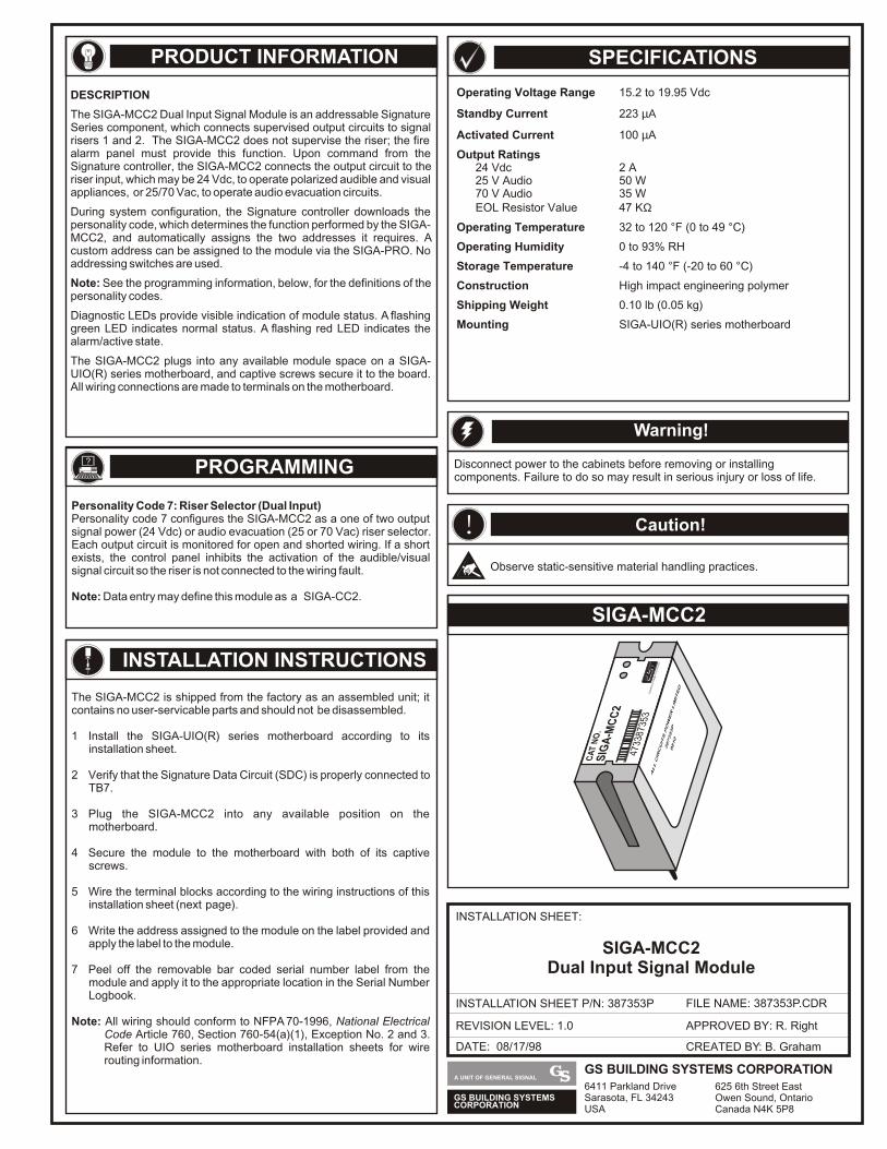
CA
T N
O.
SIG
A-M
CC
2
4733
8735
3E
DW
AR
DS
SY
ST
EM
S T
EC
HN
OLO
GY
ALL CIRCUITS POWER LIMITED
387353P
9810
PRODUCT INFORMATION
SIGA-MCC2
SPECIFICATIONS
INSTALLATION INSTRUCTIONS
DATE: 08/17/98
INSTALLATION SHEET:
INSTALLATION SHEET P/N: 387353P FILE NAME: 387353P.CDR
REVISION LEVEL: 1.0
CREATED BY: B. Graham
APPROVED BY: R. Right
SIGA-MCC2Dual Input Signal Module
Operating Voltage Range 15.2 to 19.95 Vdc
Standby Current 223 µΑ
Activated Current 100 µA
Output Ratings24 Vdc 2 A25 V Audio 50 W70 V Audio 35 WEOL Resistor Value 47 KΩ
Operating Temperature 32 to 120 °F (0 to 49 °C)
Operating Humidity 0 to 93% RH
Storage Temperature -4 to 140 °F (-20 to 60 °C)
Construction High impact engineering polymer
Shipping Weight 0.10 lb (0.05 kg)
Mounting SIGA-UIO(R) series motherboard
The SIGA-MCC2 is shipped from the factory as an assembled unit; it contains no user-servicable parts and should not be disassembled.
1 Install the SIGA-UIO(R) series motherboard according to its installation sheet.
2 Verify that the Signature Data Circuit (SDC) is properly connected to TB7.
3 Plug the SIGA-MCC2 into any available position on the motherboard.
4 Secure the module to the motherboard with both of its captive screws.
5 Wire the terminal blocks according to the wiring instructions of this installation sheet (next page).
6 Write the address assigned to the module on the label provided and apply the label to the module.
7 Peel off the removable bar coded serial number label from the module and apply it to the appropriate location in the Serial Number Logbook.
Note: All wiring should conform to NFPA 70-1996, National Electrical Code Article 760, Section 760-54(a)(1), Exception No. 2 and 3. Refer to UIO series motherboard installation sheets for wire routing information.
DESCRIPTION
The SIGA-MCC2 Dual Input Signal Module is an addressable Signature Series component, which connects supervised output circuits to signal risers 1 and 2. The SIGA-MCC2 does not supervise the riser; the fire alarm panel must provide this function. Upon command from the Signature controller, the SIGA-MCC2 connects the output circuit to the riser input, which may be 24 Vdc, to operate polarized audible and visual appliances, or 25/70 Vac, to operate audio evacuation circuits.
During system configuration, the Signature controller downloads the personality code, which determines the function performed by the SIGA-MCC2, and automatically assigns the two addresses it requires. A custom address can be assigned to the module via the SIGA-PRO. No addressing switches are used.
Note: See the programming information, below, for the definitions of the personality codes.
Diagnostic LEDs provide visible indication of module status. A flashing green LED indicates normal status. A flashing red LED indicates the alarm/active state.
The SIGA-MCC2 plugs into any available module space on a SIGA-UIO(R) series motherboard, and captive screws secure it to the board. All wiring connections are made to terminals on the motherboard.
? PROGRAMMING
Personality Code 7: Riser Selector (Dual Input)Personality code 7 configures the SIGA-MCC2 as a one of two output signal power (24 Vdc) or audio evacuation (25 or 70 Vac) riser selector. Each output circuit is monitored for open and shorted wiring. If a short exists, the control panel inhibits the activation of the audible/visual signal circuit so the riser is not connected to the wiring fault.
Note: Data entry may define this module as a SIGA-CC2.
Disconnect power to the cabinets before removing or installing components. Failure to do so may result in serious injury or loss of life.
Warning!
! Caution!
Observe static-sensitive material handling practices.
GS BUILDING SYSTEMSCORPORATION
A UNIT OF GENERAL SIGNALGS BUILDING SYSTEMS CORPORATION6411 Parkland DriveSarasota, FL 34243USA
625 6th Street EastOwen Sound, OntarioCanada N4K 5P8
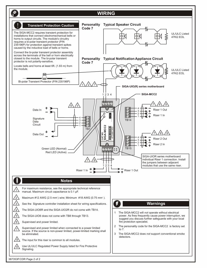
Riser 1 Out
Riser 2 Out
Riser 1 Out
TB14
TB15Green LED (Normal)
SIGA-UIO(R) series motherboard
SIGA-MCC2
1 2
Riser 1 In
Riser 2 In
Riser 1 In
Red LED (Active)
CA
T N
O.
SIG
A-M
CC
2
47
33
87
35
3E
DW
AR
DS
SY
ST
EM
S T
EC
HN
OL
OG
Y
WIRING
1 The SIGA-MCC2 will not operate without electrical power. As fires frequently cause power interruption, we suggest you discuss further safeguards with your local fire protection specialist.
2 The personality code for the SIGA-MCC2 is factory set to 7.
3 The SIGA-MCC2 does not support conventional smoke detectors.
Warnings
Notes
UL/ULC Listed47KΩ EOL
UL/ULC Listed47KΩ EOL
Typical Notification Appliance Circuit
Typical Speaker Circuit
1 2 3 4
4321
4321
1 2 3 4
PersonalityCode 7
PersonalityCode 7
SIGA-UIOR series motherboard individual Riser 1 connection. Install the jumpers between adjacent modules that use the same riser.
387353P.CDR Page 2 of 2
The SIGA-MCC2 requires transient protection for installations that connect electromechanical bells or horns to output circuits. The module's circuitry requires a bi-polar transient protector (P/N 235196P) for protection against transient spikes caused by the inductive load of bells or horns.
Connect the bi-polar transient protector assembly across the terminals of the bell or horn electrically closest to the module. The bi-polar transient protector is not polarity-sensitive.
Locate bells and horns at least 6ft. (1.83 m) from the module.
Bi-polar Transient Protector (P/N 235196P)
Transient Protection Caution!
For maximum resistance, see the appropriate technical reference manual. Maximum circuit capacitance is 0.1 µF.
Supervised and power limited when connected to a power limited source. If the source is non-power limited, power-limited marking shall be eliminated.
The input for this riser is common to all modules.
Use UL/ULC Regulated Power Supply listed for Fire Protective Signaling.
2 2Maximum #12 AWG (2.5 mm ) wire; Minimum #18 AWG (0.75 mm ).
See the Signature controller installation sheet for wiring specifications.
The SIGA-UIO6R and the SIGA-UIO2R do not come with TB14.
The SIGA-UIO6 does not come with TB8 through TB13.
Supervised and power limited.
3
1
2
4
5
6
7
Data Out
TB7
SignatureDataCircuit
Data In
4321
36
8
7
7 8 9
7 8 9
7 9
+ +
_ _
+ +
_ _
+ +
_ _
9
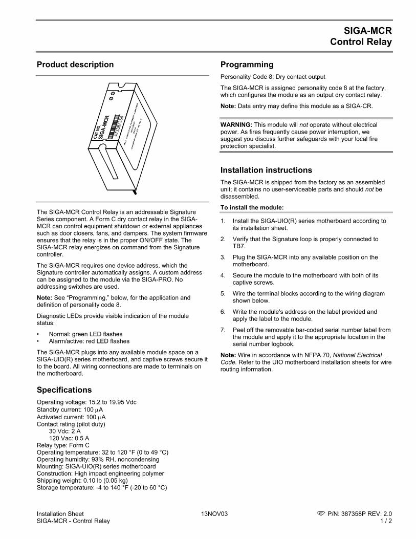
Installation Sheet 13NOV03 P/N: 387358P REV: 2.0 SIGA-MCR - Control Relay 1 / 2
SIGA-MCR Control Relay
Product description
The SIGA-MCR Control Relay is an addressable Signature Series component. A Form C dry contact relay in the SIGA-MCR can control equipment shutdown or external appliances such as door closers, fans, and dampers. The system firmware ensures that the relay is in the proper ON/OFF state. The SIGA-MCR relay energizes on command from the Signature controller.
The SIGA-MCR requires one device address, which the Signature controller automatically assigns. A custom address can be assigned to the module via the SIGA-PRO. No addressing switches are used.
Note: See “Programming,” below, for the application and definition of personality code 8.
Diagnostic LEDs provide visible indication of the module status:
• Normal: green LED flashes • Alarm/active: red LED flashes
The SIGA-MCR plugs into any available module space on a SIGA-UIO(R) series motherboard, and captive screws secure it to the board. All wiring connections are made to terminals on the motherboard.
Specifications Operating voltage: 15.2 to 19.95 Vdc Standby current: 100 µA Activated current: 100 µA Contact rating (pilot duty) 30 Vdc: 2 A 120 Vac: 0.5 A Relay type: Form C Operating temperature: 32 to 120 °F (0 to 49 °C) Operating humidity: 93% RH, noncondensing Mounting: SIGA-UIO(R) series motherboard Construction: High impact engineering polymer Shipping weight: 0.10 lb (0.05 kg) Storage temperature: -4 to 140 °F (-20 to 60 °C)
Programming Personality Code 8: Dry contact output
The SIGA-MCR is assigned personality code 8 at the factory, which configures the module as an output dry contact relay.
Note: Data entry may define this module as a SIGA-CR.
WARNING: This module will not operate without electrical power. As fires frequently cause power interruption, we suggest you discuss further safeguards with your local fire protection specialist.
Installation instructions The SIGA-MCR is shipped from the factory as an assembled unit; it contains no user-serviceable parts and should not be disassembled.
To install the module:
1. Install the SIGA-UIO(R) series motherboard according to its installation sheet.
2. Verify that the Signature loop is properly connected to TB7.
3. Plug the SIGA-MCR into any available position on the motherboard.
4. Secure the module to the motherboard with both of its captive screws.
5. Wire the terminal blocks according to the wiring diagram shown below.
6. Write the module's address on the label provided and apply the label to the module.
7. Peel off the removable bar-coded serial number label from the module and apply it to the appropriate location in the serial number logbook.
Note: Wire in accordance with NFPA 70, National Electrical Code. Refer to the UIO motherboard installation sheets for wire routing information.
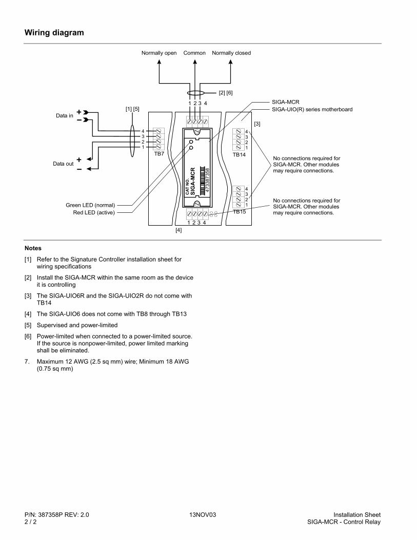
P/N: 387358P REV: 2.0 13NOV03 Installation Sheet 2 / 2 SIGA-MCR - Control Relay
Wiring diagram
4321
4321
TB14
TB15Green LED (normal)
Red LED (active)
TB7
4321
[1] [5]
Data out
Data in
CAT
NO
.S
IGA
-MC
R
4733
8735
8
[2] [6]
1 2 3 4
[3]
[4]
SIGA-UIO(R) series motherboardSIGA-MCR
Normally open Normally closedCommon
1 2 3 4
No connections required for SIGA-MCR. Other modules may require connections.
No connections required for SIGA-MCR. Other modules may require connections.
Notes
[1] Refer to the Signature Controller installation sheet for wiring specifications
[2] Install the SIGA-MCR within the same room as the device it is controlling
[3] The SIGA-UIO6R and the SIGA-UIO2R do not come with TB14
[4] The SIGA-UIO6 does not come with TB8 through TB13
[5] Supervised and power-limited
[6] Power-limited when connected to a power-limited source. If the source is nonpower-limited, power limited marking shall be eliminated.
7. Maximum 12 AWG (2.5 sq mm) wire; Minimum 18 AWG (0.75 sq mm)
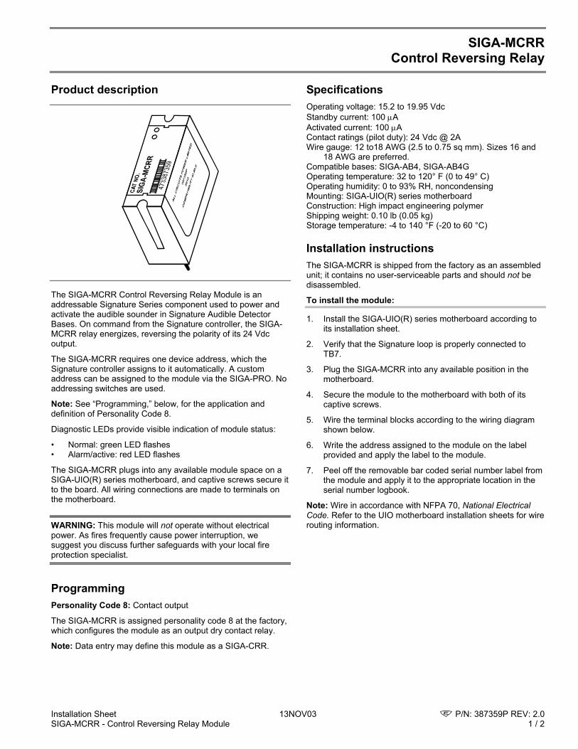
Installation Sheet 13NOV03 P/N: 387359P REV: 2.0 SIGA-MCRR - Control Reversing Relay Module 1 / 2
SIGA-MCRR Control Reversing Relay
Product description
The SIGA-MCRR Control Reversing Relay Module is an addressable Signature Series component used to power and activate the audible sounder in Signature Audible Detector Bases. On command from the Signature controller, the SIGA-MCRR relay energizes, reversing the polarity of its 24 Vdc output.
The SIGA-MCRR requires one device address, which the Signature controller assigns to it automatically. A custom address can be assigned to the module via the SIGA-PRO. No addressing switches are used.
Note: See “Programming,” below, for the application and definition of Personality Code 8.
Diagnostic LEDs provide visible indication of module status:
• Normal: green LED flashes • Alarm/active: red LED flashes
The SIGA-MCRR plugs into any available module space on a SIGA-UIO(R) series motherboard, and captive screws secure it to the board. All wiring connections are made to terminals on the motherboard.
WARNING: This module will not operate without electrical power. As fires frequently cause power interruption, we suggest you discuss further safeguards with your local fire protection specialist.
Programming Personality Code 8: Contact output
The SIGA-MCRR is assigned personality code 8 at the factory, which configures the module as an output dry contact relay.
Note: Data entry may define this module as a SIGA-CRR.
Specifications Operating voltage: 15.2 to 19.95 Vdc Standby current: 100 µA Activated current: 100 µA Contact ratings (pilot duty): 24 Vdc @ 2A Wire gauge: 12 to18 AWG (2.5 to 0.75 sq mm). Sizes 16 and
18 AWG are preferred. Compatible bases: SIGA-AB4, SIGA-AB4G Operating temperature: 32 to 120° F (0 to 49° C) Operating humidity: 0 to 93% RH, noncondensing Mounting: SIGA-UIO(R) series motherboard Construction: High impact engineering polymer Shipping weight: 0.10 lb (0.05 kg) Storage temperature: -4 to 140 °F (-20 to 60 °C)
Installation instructions The SIGA-MCRR is shipped from the factory as an assembled unit; it contains no user-serviceable parts and should not be disassembled.
To install the module:
1. Install the SIGA-UIO(R) series motherboard according to its installation sheet.
2. Verify that the Signature loop is properly connected to TB7.
3. Plug the SIGA-MCRR into any available position in the motherboard.
4. Secure the module to the motherboard with both of its captive screws.
5. Wire the terminal blocks according to the wiring diagram shown below.
6. Write the address assigned to the module on the label provided and apply the label to the module.
7. Peel off the removable bar coded serial number label from the module and apply it to the appropriate location in the serial number logbook.
Note: Wire in accordance with NFPA 70, National Electrical Code. Refer to the UIO motherboard installation sheets for wire routing information.
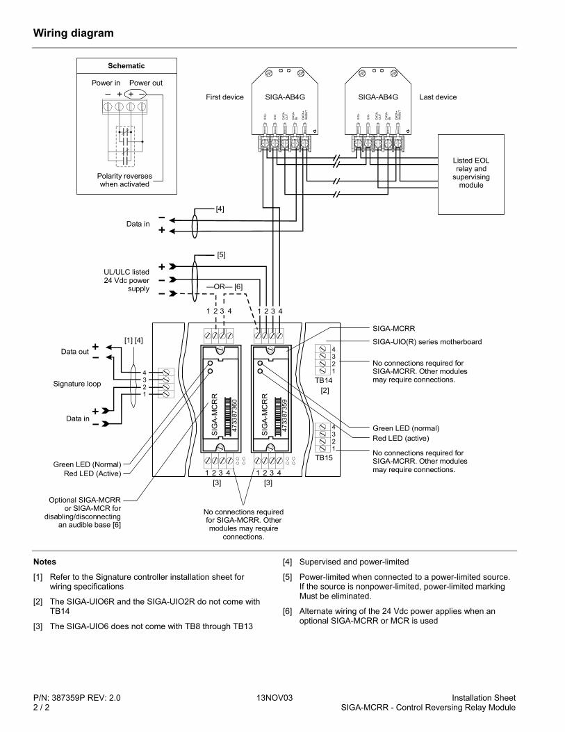
P/N: 387359P REV: 2.0 13NOV03 Installation Sheet 2 / 2 SIGA-MCRR - Control Reversing Relay Module
Wiring diagram
Data in
—OR— [6]
4321
4321
TB14
TB15Green LED (Normal)
Green LED (normal)
Red LED (Active)
Red LED (active)
CAT
NO
.
CAT
NO
.
SIG
A-M
CR
R
4733
8736
0
SIG
A-M
CR
R
4733
8735
9
[2]
1 12 23 34 4
[4]
[5]
[3]
No connections required for SIGA-MCRR. Other modules may require connections.
No connections required for SIGA-MCRR. Other modules may require connections.
No connections required for SIGA-MCRR. Other modules may require
connections.
1 2 3 4
SIGA-UIO(R) series motherboard
SIGA-MCRR
Optional SIGA-MCRRor SIGA-MCR for
disabling/disconnectingan audible base [6]
UL/ULC listed 24 Vdc power
supply
1 2 3 4
TB7
Data out
Data in
4321
[1] [4]
Signature loop
[3]
SIG
+
SIG
-
DAT
A+
IN/O
UT
SIGA-AB4G
Listed EOL relay and
supervising module
SIG
+
SIG
-
DAT
A+
IN/O
UT
SIGA-AB4GFirst device Last device
Power in Power out
Polarity reverses when activated
+– + –
Schematic
Notes
[1] Refer to the Signature controller installation sheet for wiring specifications
[2] The SIGA-UIO6R and the SIGA-UIO2R do not come with TB14
[3] The SIGA-UIO6 does not come with TB8 through TB13
[4] Supervised and power-limited
[5] Power-limited when connected to a power-limited source. If the source is nonpower-limited, power-limited marking Must be eliminated.
[6] Alternate wiring of the 24 Vdc power applies when an optional SIGA-MCRR or MCR is used
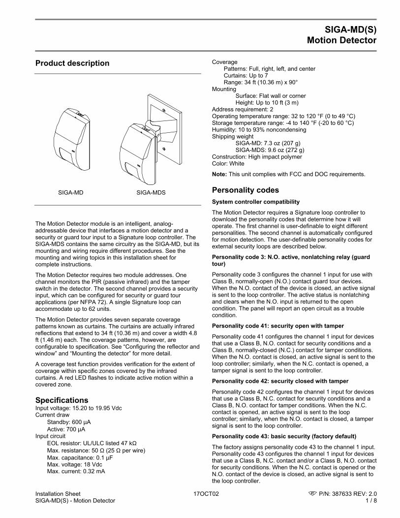
Installation Sheet 17OCT02 P/N: 387633 REV: 2.0SIGA-MD(S) - Motion Detector 1 / 8
SIGA-MD(S)Motion Detector
Product description
The Motion Detector module is an intelligent, analog-addressable device that interfaces a motion detector and asecurity or guard tour input to a Signature loop controller. TheSIGA-MDS contains the same circuitry as the SIGA-MD, but itsmounting and wiring require different procedures. See themounting and wiring topics in this installation sheet forcomplete instructions.
The Motion Detector requires two module addresses. Onechannel monitors the PIR (passive infrared) and the tamperswitch in the detector. The second channel provides a securityinput, which can be configured for security or guard tourapplications (per NFPA 72). A single Signature loop canaccommodate up to 62 units.
The Motion Detector provides seven separate coveragepatterns known as curtains. The curtains are actually infraredreflections that extend to 34 ft (10.36 m) and cover a width 4.8ft (1.46 m) each. The coverage patterns, however, areconfigurable to specification. See “Configuring the reflector andwindow” and “Mounting the detector” for more detail.
A coverage test function provides verification for the extent ofcoverage within specific zones covered by the infraredcurtains. A red LED flashes to indicate active motion within acovered zone.
SpecificationsInput voltage: 15.20 to 19.95 VdcCurrent draw
Standby: 600 µAActive: 700 µA
Input circuitEOL resistor: UL/ULC listed 47 kΩMax. resistance: 50 Ω (25 Ω per wire)Max. capacitance: 0.1 µFMax. voltage: 18 VdcMax. current: 0.32 mA
CoveragePatterns: Full, right, left, and centerCurtains: Up to 7Range: 34 ft (10.36 m) x 90°
MountingSurface: Flat wall or cornerHeight: Up to 10 ft (3 m)
Address requirement: 2Operating temperature range: 32 to 120 °F (0 to 49 °C)Storage temperature range: -4 to 140 °F (-20 to 60 °C)Humidity: 10 to 93% noncondensingShipping weight
SIGA-MD: 7.3 oz (207 g)SIGA-MDS: 9.6 oz (272 g)
Construction: High impact polymerColor: White
Note: This unit complies with FCC and DOC requirements.
Personality codesSystem controller compatibility
The Motion Detector requires a Signature loop controller todownload the personality codes that determine how it willoperate. The first channel is user-definable to eight differentpersonalities. The second channel is automatically configuredfor motion detection. The user-definable personality codes forexternal security loops are described below.
Personality code 3: N.O. active, nonlatching relay (guardtour)
Personality code 3 configures the channel 1 input for use withClass B, normally-open (N.O.) contact guard tour devices.When the N.O. contact of the device is closed, an active signalis sent to the loop controller. The active status is nonlatchingand clears when the N.O. input is returned to the opencondition. The panel will report an open circuit as a troublecondition.
Personality code 41: security open with tamper
Personality code 41 configures the channel 1 input for devicesthat use a Class B, N.O. contact for security conditions and aClass B, normally-closed (N.C.) contact for tamper conditions.When the N.O. contact is closed, an active signal is sent to theloop controller; similarly, when the N.C. contact is opened, atamper signal is sent to the loop controller.
Personality code 42: security closed with tamper
Personality code 42 configures the channel 1 input for devicesthat use a Class B, N.C. contact for security conditions and aClass B, N.O. contact for tamper conditions. When the N.C.contact is opened, an active signal is sent to the loopcontroller; similarly, when the N.O. contact is closed, a tampersignal is sent to the loop controller.
Personality code 43: basic security (factory default)
The factory assigns personality code 43 to the channel 1 input.Personality code 43 configures the channel 1 input for devicesthat use a Class B, N.C. contact and/or a Class B, N.O. contactfor security conditions. When the N.C. contact is opened or theN.O. contact of the device is closed, an active signal is sent tothe loop controller.
SIGA-MD SIGA-MDS
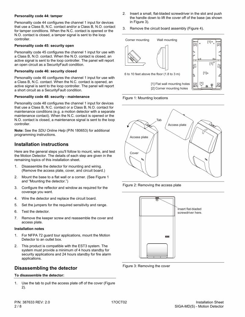
P/N: 387633 REV: 2.0 17OCT02 Installation Sheet2 / 8 SIGA-MD(S) - Motion Detector
Personality code 44: tamper
Personality code 44 configures the channel 1 input for devicesthat use a Class B, N.C. contact and/or a Class B, N.O. contactfor tamper conditions. When the N.C. contact is opened or theN.O. contact is closed, a tamper signal is sent to the loopcontroller.
Personality code 45: security open
Personality code 45 configures the channel 1 input for use witha Class B, N.O. contact. When the N.O. contact is closed, anactive signal is sent to the loop controller. The panel will reportan open circuit as a SecurityFault condition.
Personality code 46: security closed
Personality code 46 configures the channel 1 input for use witha Class B, N.C. contact. When the N.C. contact is opened, anactive signal is sent to the loop controller. The panel will reporta short circuit as a SecurityFault condition.
Personality code 48: security - maintenance
Personality code 48 configures the channel 1 input for devicesthat use a Class B, N.C. contact or a Class B, N.O. contact formaintenance conditions (e.g. a motion detector with a separatemaintenance contact). When the N.C. contact is opened or theN.O. contact is closed, a maintenance signal is sent to the loopcontroller.
Note: See the SDU Online Help (P/N 180653) for additionalprogramming instructions.
Installation instructionsHere are the general steps you'll follow to mount, wire, and testthe Motion Detector. The details of each step are given in theremaining topics of this installation sheet.
1. Disassemble the detector for mounting and wiring.(Remove the access plate, cover, and circuit board.)
2. Mount the base to a flat wall or a corner. (See Figure 1and “Mounting the detector.”)
3. Configure the reflector and window as required for thecoverage you want.
4. Wire the detector and replace the circuit board.
5. Set the jumpers for the required sensitivity and range.
6. Test the detector.
7. Remove the keeper screw and reassemble the cover andaccess plate.
Installation notes
1. For NFPA 72 guard tour applications, mount the MotionDetector to an outlet box.
2. This product is compatible with the EST3 system. Thesystem must provide a minimum of 4 hours standby forsecurity applications and 24 hours standby for fire alarmapplications.
Disassembling the detectorTo disassemble the detector:
1. Use the tab to pull the access plate off of the cover (Figure2).
2. Insert a small, flat-bladed screwdriver in the slot and pushthe handle down to lift the cover off of the base (as shownin Figure 3).
3. Remove the circuit board assembly (Figure 4).
[1][2]
[2] Corner mounting holes[1] Flat wall mounting holes
Corner mounting Wall mounting[2]
[1]
[1]
[1][2] [2]
6 to 10 feet above the floor (1.8 to 3 m)
Figure 1: Mounting locations
Cover
Access plate
TabAccess plate
Figure 2: Removing the access plate
Insert flat-bladed screwdriver here.
Figure 3: Removing the cover
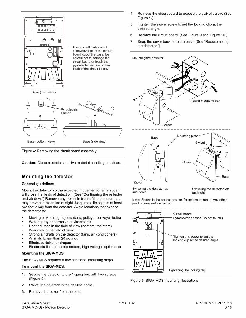
Installation Sheet 17OCT02 P/N: 387633 REV: 2.0SIGA-MD(S) - Motion Detector 3 / 8
Use a small, flat-bladed screwdriver to lift the circuit board out of the base. Be careful not to damage the circuit board or touch the pyroelectric sensor on the back of the circuit board.
Base (front view)
Base (bottom view) Base (side view)
Pyroelectricsensor
Figure 4: Removing the circuit board assembly
Caution: Observe static-sensitive material handling practices.
Mounting the detectorGeneral guidelines
Mount the detector so the expected movement of an intruderwill cross the fields of detection. (See “Configuring the reflectorand window.”) Remove any object in front of the detector thatmay prevent a clear line of sight. Keep metallic objects at leasttwo feet away from the detector. Avoid locations that exposethe detector to:
• Moving or vibrating objects (fans, pulleys, conveyer belts)• Water spray or corrosive environments• Heat sources in the field of view (heaters, radiators)• Windows in the field of view• Strong air drafts on the detector (fans, air conditioners)• Animals larger than 20 pounds• Blinds, curtains, or drapes• Electronic fields (electric motors, high-voltage equipment)
Mounting the SIGA-MDS
The SIGA-MDS requires a few additional mounting steps.
To mount the SIGA-MDS:
1. Secure the detector to the 1-gang box with two screws(Figure 5).
2. Swivel the detector to the desired angle.
3. Remove the cover from the base.
4. Remove the circuit board to expose the swivel screw. (SeeFigure 4.)
5. Tighten the swivel screw to set the locking clip at thedesired angle.
6. Replace the circuit board. (See Figure 9 and Figure 10.)
7. Snap the cover back onto the base. (See “Reassemblingthe detector.”)
Screw
1-gang mounting box
Mounting the detector
Circuit board
Tighten this screw to set the locking clip at the desired angle.
Tightening the locking clip
Mounting plate
SwivelBase
Cover
Swiveling the detector up and down
Note: Shown in the correct position for maximum range. Any other position may reduce range.
Swiveling the detector left and right
Base
Pyroelectric sensor (Do not touch!)
Cover
Figure 5: SIGA-MDS mounting illustrations
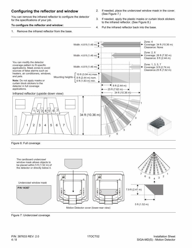
P/N: 387633 REV: 2.0 17OCT02 Installation Sheet4 / 8 SIGA-MD(S) - Motion Detector
Configuring the reflector and windowYou can remove the infrared reflector to configure the detectorfor the specifications of your job.
To configure the reflector and window:
1. Remove the infrared reflector from the base.
2. If needed, place the undercrawl window mask in the cover.(See Figure 7.)
3. If needed, apply the plastic masks or curtain block stickersto the infrared reflector. (See Figure 8.)
4. Put the infrared reflector back into the base.
10 ft (3.04 m) max.
8 ft (2.44 m)
8 ft (2.44 m) nom.6 ft (1.83 m) min.
25 ft (7.62 m)34 ft (10.36 m)
Zone: 4Coverage: 34 ft (10.36 m)Clearance: None
Zone: 2, 6Coverage: 26 ft (7.92 m)Clearance: 8 ft (2.44 m)
Zone: 1, 3, 5, 7Coverage: 9 ft (2.74 m)Clearance 25 ft (7.62 m)
Width: 4.8 ft (1.46 m)
Width: 4.8 ft (1.46 m)
Width: 4.8 ft (1.46 m)
Mounting heights
76
5
4
3
2
1
Infrared reflector (upside down view)
1 2 3 4 5 6 7
1 2 3 4 5 6 734 ft (10.36 m)
You can modify the detector coverage pattern to fit specific applications. Mask zones to avoid sources of false alarms such as heaters, air conditioners, windows, and pets.
Note: Do not apply masks or curtain block stickers to the detector in full coverage applications.
Figure 6: Full coverage
P/N 14367
76 5 2
1
4 3
7.9 ft (2.41 m)
5 ft (1.52 m)
Undercrawl window mask
Motion Detector cover (lower-rear view)
The cardboard undercrawl window mask allows objects to be placed within 5 ft (1.52 m) of the detector or directly below it.
Figure 7: Undercrawl coverage
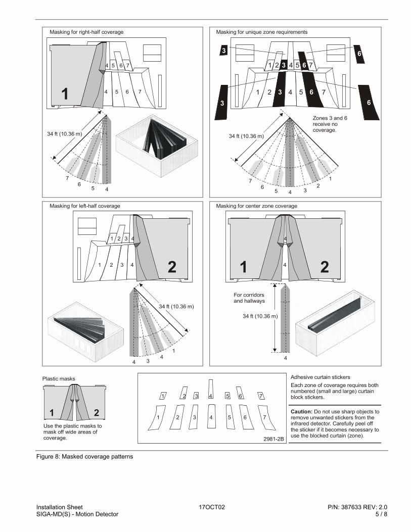
Installation Sheet 17OCT02 P/N: 387633 REV: 2.0SIGA-MD(S) - Motion Detector 5 / 8
76
5 4
34 ft (10.36 m)
1 2 3 4 5 6 7
1 2 3 4 5 6 7
2
14
34
34 ft (10.36 m)
76
5 4 32
1
3 6
3 673
3
1 2 4 5 6
1 2 4 5 76
34 ft (10.36 m)
Zones 3 and 6 receive no coverage.
1 2 3 4 5 6 7
1 2 3 4 5 6 7
1 2For corridorsand hallways
4
34 ft (10.36 m)
Masking for right-half coverage
Masking for left-half coverage
Masking for unique zone requirements
Masking for center zone coverage
1 2
2981-2B
1
1
2 3 4 5 6 7
2 3 4 5 6 7
Use the plastic masks to mask off wide areas of coverage.
Each zone of coverage requires both numbered (small and large) curtain block stickers.
Plastic masks Adhesive curtain stickers
Caution: Do not use sharp objects to remove unwanted stickers from the infrared detector. Carefully peel off the sticker if it becomes necessary to use the blocked curtain (zone).
1 2 3 4 5 6 7
1 2 3 4 5 6 7
1
Figure 8: Masked coverage patterns
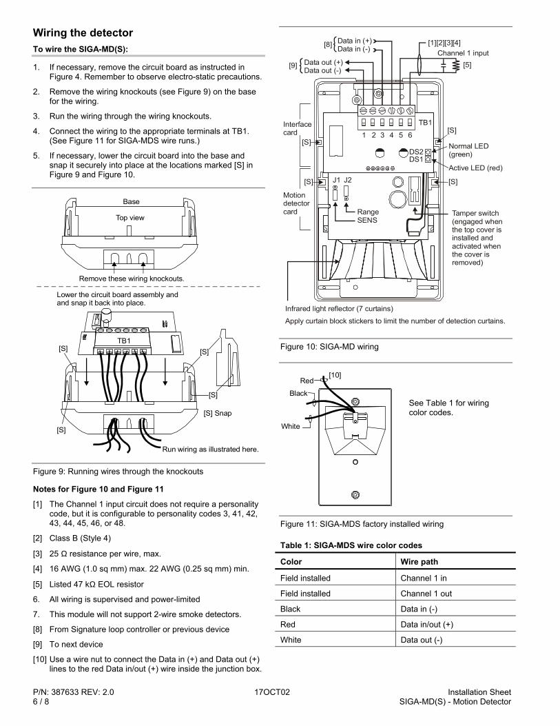
P/N: 387633 REV: 2.0 17OCT02 Installation Sheet6 / 8 SIGA-MD(S) - Motion Detector
Wiring the detectorTo wire the SIGA-MD(S):
1. If necessary, remove the circuit board as instructed inFigure 4. Remember to observe electro-static precautions.
2. Remove the wiring knockouts (see Figure 9) on the basefor the wiring.
3. Run the wiring through the wiring knockouts.
4. Connect the wiring to the appropriate terminals at TB1.(See Figure 11 for SIGA-MDS wire runs.)
5. If necessary, lower the circuit board into the base andsnap it securely into place at the locations marked [S] inFigure 9 and Figure 10.
Run wiring as illustrated here.
Top view
Remove these wiring knockouts.
Base
Lower the circuit board assembly andand snap it back into place.
[S]
[S] Snap
[S]
[S]
[S]
TB1
Figure 9: Running wires through the knockouts
Notes for Figure 10 and Figure 11
[1] The Channel 1 input circuit does not require a personalitycode, but it is configurable to personality codes 3, 41, 42,43, 44, 45, 46, or 48.
[2] Class B (Style 4)
[3] 25 Ω resistance per wire, max.
[4] 16 AWG (1.0 sq mm) max. 22 AWG (0.25 sq mm) min.
[5] Listed 47 kΩ EOL resistor
6. All wiring is supervised and power-limited
7. This module will not support 2-wire smoke detectors.
[8] From Signature loop controller or previous device
[9] To next device
[10] Use a wire nut to connect the Data in (+) and Data out (+)lines to the red Data in/out (+) wire inside the junction box.
1 2 3 4 5 6
TB1
DS1DS2
SENSRange
Normal LED(green)
Active LED (red)
Tamper switch (engaged when the top cover is installed and activated when the cover is removed)
Infrared light reflector (7 curtains)
Apply curtain block stickers to limit the number of detection curtains.
Data in (+)Data in (-)
Data out (+)Data out (-)
Channel 1 input
Motiondetectorcard
Interfacecard
[S] [S]
[S][S]
[1]
[5]
J1 J2
[2][3][4][8]
[9]
Figure 10: SIGA-MD wiring
Red
Black
White
[10]
Figure 11: SIGA-MDS factory installed wiring
Table 1: SIGA-MDS wire color codes
Color Wire path
Field installed Channel 1 in
Field installed Channel 1 out
Black Data in (-)
Red Data in/out (+)
White Data out (-)
See Table 1 for wiringcolor codes.
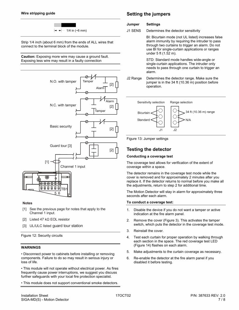
Installation Sheet 17OCT02 P/N: 387633 REV: 2.0SIGA-MD(S) - Motion Detector 7 / 8
Wire stripping guide
1/4 in (~6 mm)
Strip 1/4 inch (about 6 mm) from the ends of ALL wires thatconnect to the terminal block of the module.
Caution: Exposing more wire may cause a ground fault.Exposing less wire may result in a faulty connection
Channel 1 input
Basic security
N.C. with tamper
N.O. with tamper
Guard tour [3]
5 6TB1
[1]
Tamper
Alarm
Alarm
Tamper
[2]
[2]
[2]
[2]
Notes[1] See the previous page for notes that apply to the
Channel 1 input.
[2] Listed 47 k EOL resistor
[3] UL/ULC listed
Ω
guard tour station
Figure 12: Security circuits
WARNINGS
• Disconnect power to cabinets before installing or removingcomponents. Failure to do so may result in serious injury orloss of life.
• This module will not operate without electrical power. As firesfrequently cause power interruptions, we suggest you discussfurther safeguards with your local fire protection specialist.
• This module does not support conventional smoke detectors.
Setting the jumpers
Jumper Settings
J1 SENS Determines the detector sensitivity
BI: Bicurtain mode (not UL listed) increases falsealarm immunity by requiring the intruder to passthrough two curtains to trigger an alarm. Do notuse BI for single-curtain applications or rangesunder 5 ft (1.52 m).
STD: Standard mode handles wide-angle orsingle-curtain applications. The intruder onlyneeds to pass through one curtain to trigger analarm.
J2 Range Determines the detector range. Make sure thejumper is in the 34 ft (10.36 m) position beforeoperation.
J1 J2
Sensitivity selection Range selection
Standard
34 ft (10.36 m) range
N/A
Bicurtain
Figure 13: Jumper settings
Testing the detectorConducting a coverage test
The coverage test allows for verification of the extent ofcoverage within a space.
The detector remains in the coverage test mode while thecover is removed and for approximately 2 minutes after youreplace it. If the detector returns to normal before you make allthe adjustments, return to step 2 for additional time.
The Motion Detector will stay in alarm for approximately threeseconds after each alarm.
To conduct a coverage test:
1. Disable the device if you do not want a tamper or activeindication at the fire alarm panel.
2. Remove the cover (Figure 3). This activates the tamperswitch, which puts the detector in the coverage test mode.
3. Reinstall the cover.
4. Test each curtain for proper operation by walking througheach section in the space. The red coverage test LED(Figure 14) flashes on each alarm.
5. Make adjustments to the curtain coverage as necessary.
6. Re-enable the detector at the fire alarm panel if youdisabled it before testing.
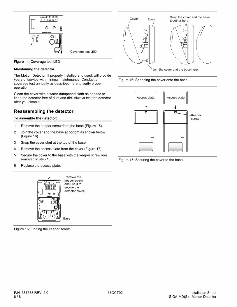
P/N: 387633 REV: 2.0 17OCT02 Installation Sheet8 / 8 SIGA-MD(S) - Motion Detector
Coverage test LED
J1 J2
Figure 14: Coverage test LED
Maintaining the detector
The Motion Detector, if properly installed and used, will provideyears of service with minimal maintenance. Conduct acoverage test annually as described here to verify properoperation.
Clean the cover with a water-dampened cloth as needed tokeep the detector free of dust and dirt. Always test the detectorafter you clean it.
Reassembling the detectorTo assemble the detector:
1 Remove the keeper screw from the base (Figure 15).
2 Join the cover and the base at bottom as shown below(Figure 16).
3 Snap the cover shut at the top of the base.
4 Remove the access plate from the cover (Figure 17).
5 Secure the cover to the base with the keeper screw youremoved in step 1.
6 Replace the access plate.
Remove the keeper screw and use it to secure the detector cover.
Figure 15: Finding the keeper screw
BaseCover
Join the cover and the base here.
Snap the cover and the base together here.
Figure 16: Snapping the cover onto the base
Keeperscrew
Figure 17: Securing the cover to the base
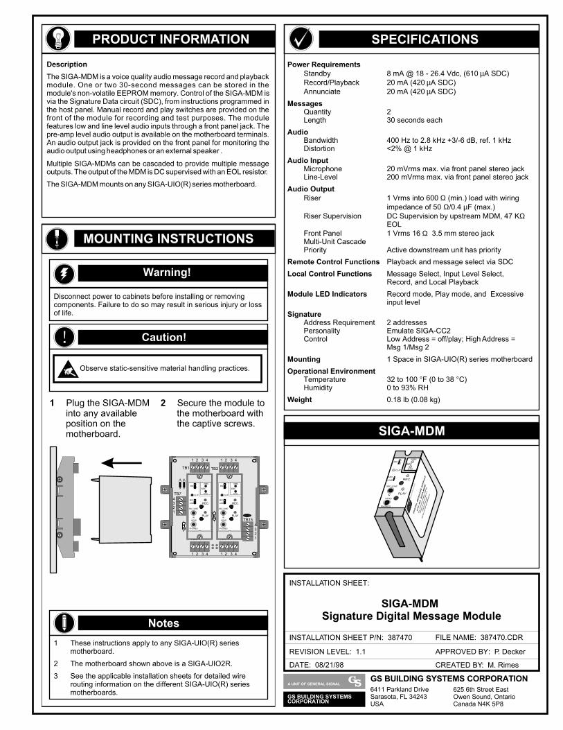
PRODUCT INFORMATION
SIGA-MDM
SPECIFICATIONS
DATE: 08/21/98
INSTALLATION SHEET:
INSTALLATION SHEET P/N: 387470 FILE NAME: 387470.CDR
REVISION LEVEL: 1.1
CREATED BY: M. Rimes
APPROVED BY: P. Decker
SIGA-MDM Signature Digital Message Module
Power RequirementsStandby 8 mA @ 18 - 26.4 Vdc, (610 µA SDC)Record/Playback 20 mA (420 µA SDC)Annunciate 20 mA (420 µA SDC)
MessagesQuantity 2Length 30 seconds each
AudioBandwidth 400 Hz to 2.8 kHz +3/-6 dB, ref. 1 kHzDistortion <2% @ 1 kHz
Audio InputMicrophone 20 mVrms max. via front panel stereo jackLine-Level 200 mVrms max. via front panel stereo jack
Audio OutputRiser 1 Vrms into 600 Ω (min.) load with wiring
impedance of 50 Ω/0.4 µF (max.)Riser Supervision DC Supervision by upstream MDM, 47 KΩ
EOLFront Panel 1 Vrms 16 Ω 3.5 mm stereo jackMulti-Unit CascadePriority Active downstream unit has priority
Remote Control Functions Playback and message select via SDC
Local Control Functions Message Select, Input Level Select, Record, and Local Playback
Module LED Indicators Record mode, Play mode, and Excessive input level
SignatureAddress Requirement 2 addressesPersonality Emulate SIGA-CC2Control Low Address = off/play; High Address =
Msg 1/Msg 2
Mounting 1 Space in SIGA-UIO(R) series motherboard
Operational EnvironmentTemperature 32 to 100 °F (0 to 38 °C)Humidity 0 to 93% RH
Weight 0.18 lb (0.08 kg)
Description
The SIGA-MDM is a voice quality audio message record and playback module. One or two 30-second messages can be stored in the module's non-volatile EEPROM memory. Control of the SIGA-MDM is via the Signature Data circuit (SDC), from instructions programmed in the host panel. Manual record and play switches are provided on the front of the module for recording and test purposes. The module features low and line level audio inputs through a front panel jack. The pre-amp level audio output is available on the motherboard terminals. An audio output jack is provided on the front panel for monitoring the audio output using headphones or an external speaker .
Multiple SIGA-MDMs can be cascaded to provide multiple message outputs. The output of the MDM is DC supervised with an EOL resistor.
The SIGA-MDM mounts on any SIGA-UIO(R) series motherboard.
MOUNTING INSTRUCTIONS
1 Plug the SIGA-MDM into any available position on the motherboard.
DIGITAL MESSAGE MODULE
CAT. NO. SIGA-MDM
ALL CIRCUITS POWER LIMITED
REFER TO 387470 REV X.X
FOR RATING AND
INSTALLATION INFORMATION
PLAY
REC.
MIC./LINE
IN
HEAD
PHONES
1MSG
2
CLIP
MIC.
LINE
SDC
NORMAL
ACTIVE
EDWARDS SYSTEMS TECHNOLOGY
Warning!
Disconnect power to cabinets before installing or removing components. Failure to do so may result in serious injury or loss of life.
! Caution!
Observe static-sensitive material handling practices.
1 These instructions apply to any SIGA-UIO(R) series motherboard.
2 The motherboard shown above is a SIGA-UIO2R.
3 See the applicable installation sheets for detailed wire routing information on the different SIGA-UIO(R) series motherboards.
Notes
2 Secure the module to the motherboard with the captive screws.
4321
4321
1 2 3 4
1 2 3 4
1 2 3 4
1 2 3 4
P1 P2
TB1 TB2
TB7
TB8 TB9
TB15PLAY
REC.
MIC./LINE
IN
HEAD
PHONES
MSG1
2
CLIP
MIC.
LINE
SDC
NORMAL
ACTIVE
PLAY
REC.
MIC./LINE
IN
HEAD
PHONES
MSG1
2
CLIP
MIC.
LINE
SDC
NORMAL
ACTIVE
GS BUILDING SYSTEMSCORPORATION
A UNIT OF GENERAL SIGNALGS BUILDING SYSTEMS CORPORATION6411 Parkland DriveSarasota, FL 34243USA
625 6th Street EastOwen Sound, OntarioCanada N4K 5P8
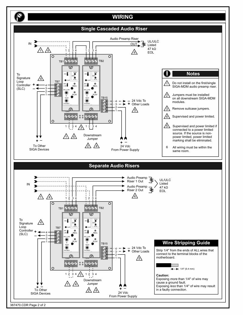
P1 P2
TB1 TB2
TB7
TB8 TB9
TB15
P1 P2
TB1 TB2
TB7
TB8 TB9
TB15
WIRING
387470.CDR Page 2 of 2
Single Cascaded Audio Riser
Separate Audio Risers
1
1
1
1
2
2
3
3
4
4
4
4
4
4
4
4
4
4
5
5
IN OUTUL/ULCListed47 kΩEOL
Audio Preamp Riser
24 Vdc ToOther Loads
24 VdcFrom Power Supply
DownstreamJumper
To OtherSIGA Devices
ToSignatureLoopController(SLC)
ToSignatureLoopController(SLC)
_
_
+
+
IN
UL/ULCListed47 kΩEOL
Audio PreampRiser 1 Out
Audio PreampRiser 2 Out
24 Vdc ToOther Loads
24 VdcFrom Power Supply
DownstreamJumper
To OtherSIGA Devices
_+
_+
_+
_+
_+
_+
Wire Stripping Guide
Strip 1/4" from the ends of ALL wires that connect to the terminal blocks of the motherboard.
Caution:Exposing more than 1/4" of wire may cause a ground fault.Exposing less than 1/4" of wire may result in a faulty connection.
1/4" (6.4 mm)
Notes
Do not install on the first/single SIGA-MDM audio preamp riser.
1
2
3
4
5
6
Supervised and power limited.
Remove suitcase jumpers.
Jumpers must be installedon all downstream SIGA-MDMmodules.
All wiring must be within the same room.
Supervised and power limited if connected to a power limited source. If the source is non-power limited, power limited marking shall be eliminated.
1 2 3 4
1 2 3 4 1 2 3 4
1 2 3 4
4321
4321
4321
4321
1 2 3 4 1 2 3 4
1 2 3 41 2 3 4
PLAY
REC.
MIC./LINE
IN
HEAD
PHONES
MSG1
2
CLIP
MIC.
LINE
SDC
NORMAL
ACTIVE
PLAY
REC.
MIC./LINE
IN
HEAD
PHONES
MSG1
2
CLIP
MIC.
LINE
SDC
NORMAL
ACTIVE
PLAY
REC.
MIC./LINE
IN
HEAD
PHONES
MSG1
2
CLIP
MIC.
LINE
SDC
NORMAL
ACTIVE
PLAY
REC.
MIC./LINE
IN
HEAD
PHONES
MSG1
2
CLIP
MIC.
LINE
SDC
NORMAL
ACTIVE
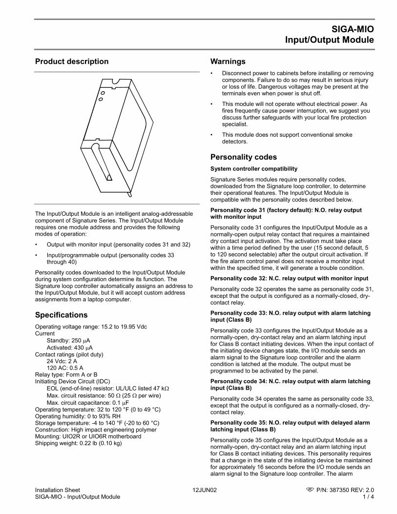
Installation Sheet 12JUN02 P/N: 387350 REV: 2.0SIGA-MIO - Input/Output Module 1 / 4
SIGA-MIOInput/Output Module
Product description
The Input/Output Module is an intelligent analog-addressablecomponent of Signature Series. The Input/Output Modulerequires one module address and provides the followingmodes of operation:
• Output with monitor input (personality codes 31 and 32)
• Input/programmable output (personality codes 33through 40)
Personality codes downloaded to the Input/Output Moduleduring system configuration determine its function. TheSignature loop controller automatically assigns an address tothe Input/Output Module, but it will accept custom addressassignments from a laptop computer.
SpecificationsOperating voltage range: 15.2 to 19.95 VdcCurrent
Standby: 250 AActivated: 430 A
Contact ratings (pilot duty)24 Vdc: 2 A120 AC: 0.5 A
Relay type: Form A or BInitiating Device Circuit (IDC)
EOL (end-of-line) resistor: UL/ULC listed 47 kMax. circuit resistance: 50 (25 per wire)Max. circuit capacitance: 0.1 F
Operating temperature: 32 to 120 °F (0 to 49 °C)Operating humidity: 0 to 93% RHStorage temperature: -4 to 140 °F (-20 to 60 °C)Construction: High impact engineering polymerMounting: UIO2R or UIO6R motherboardShipping weight: 0.22 lb (0.10 kg)
Warnings• Disconnect power to cabinets before installing or removing
components. Failure to do so may result in serious injuryor loss of life. Dangerous voltages may be present at theterminals even when power is shut off.
• This module will not operate without electrical power. Asfires frequently cause power interruption, we suggest youdiscuss further safeguards with your local fire protectionspecialist.
• This module does not support conventional smokedetectors.
Personality codesSystem controller compatibility
Signature Series modules require personality codes,downloaded from the Signature loop controller, to determinetheir operational features. The Input/Output Module iscompatible with the personality codes described below.
Personality code 31 (factory default): N.O. relay outputwith monitor input
Personality code 31 configures the Input/Output Module as anormally-open output relay contact that requires a maintaineddry contact input activation. The activation must take placewithin a time period defined by the user (15 second default, 5to 120 second selectable) after the output circuit activation. Ifthe fire alarm control panel does not receive a monitor inputwithin the specified time, it will generate a trouble condition.
Personality code 32: N.C. relay output with monitor input
Personality code 32 operates the same as personality code 31,except that the output is configured as a normally-closed, dry-contact relay.
Personality code 33: N.O. relay output with alarm latchinginput (Class B)
Personality code 33 configures the Input/Output Module as anormally-open, dry-contact relay and an alarm latching inputfor Class B contact initiating devices. When the input contact ofthe initiating device changes state, the I/O module sends analarm signal to the Signature loop controller and the alarmcondition is latched at the module. The output must beprogrammed to be activated by the panel.
Personality code 34: N.C. relay output with alarm latchinginput (Class B)
Personality code 34 operates the same as personality code 33,except that the output is configured as a normally-closed, dry-contact relay.
Personality code 35: N.O. relay output with delayed alarmlatching input (Class B)
Personality code 35 configures the Input/Output Module as anormally-open, dry-contact relay and an alarm latching inputfor Class B contact initiating devices. This personality requiresthat a change in the state of the initiating device be maintainedfor approximately 16 seconds before the I/O module sends analarm signal to the Signature loop controller. The alarm
P/N: 387350 REV: 2.0 12JUN02 Installation Sheet2 / 4 SIGA-MIO - Input/Output Module
condition is latched at the module, and the output must beprogrammed to be activated by the panel. Personality code 35is only for use with non-retarded, normally-open waterflowalarm switches.
Personality code 36: N.C. relay output with delayed alarmlatching input (Class B)
Personality code 36 operates the same as personality code 35,except that the output is configured as a normally-closed, dry-contact relay. Personality code 36 is only for use with non-retarded, normally-closed waterflow alarm switches.
Personality code 37: N.O. relay output with active non-latching input (Class B)
Personality code 37 configures the Input/Output Module as anormally-open, dry-contact relay and an active latching inputfor Class B contact initiating devices. When the input contact ofthe initiating device changes state, the I/O module sends anactive signal to the Signature loop controller. The active signaldoes not latch, and restores when the input device returns toits normal state. The output must be programmed to beactivated by the panel. Personality code 37 is typically used formonitoring normally-open fans, dampers, doors, etc.
Personality codes 38: N.C. relay output with active non-latching input (Class B)
Personality code 38 operates the same as personality code 37,except that the output is configured as a normally-closed, dry-contact relay. Personality code 38 is typically used formonitoring normally-closed fans, dampers, doors, etc.
Personality code 39: N.O. relay output with active latchinginput (Class B)
Personality code 39 configures the Input/Output Module as anormally-open, dry-contact relay and an active latching inputfor Class B contact initiating devices. When the input contact ofthe initiating device changes state, the I/O module sends anactive signal to the Signature loop controller and the activecondition is latched at the module. The output must beprogrammed to be activated by the panel.
Personality code 40: N.C. relay output with active latchinginput (Class B)
Personality code 40 operates the same as personality code 39,except that the output is configured as a normally-closed, dry-contact relay.
LEDsDiagnostic LEDs provide visible indication of the status of themodule.
Status LED indicator
Normal/Trouble Green LED flashes
Active/Alarm Red LED flashes
Installation instructions
Caution: Observe static-sensitive material handling practices.
Note: The factory ships the Input/Output Module as anassembled unit; it contains no user-serviceable parts andshould not be disassembled.
To install the Input/Output module:
1. Install the Signature motherboard (UIO2R or UIO6R). Seethe motherboard installation sheet for more information.
2. Plug the Input/Output Module into any available positionon the Signature motherboard.
3. Secure the module to the motherboard with the twocaptive screws on the module.
4. Wire the module according to the instructions in the wiringdiagram.
5. Write the address assigned to the module on the label andapply it to the module.
6. Remove the bar-coded serial number label from themodule and apply it to the appropriate location in the serialnumber log book.
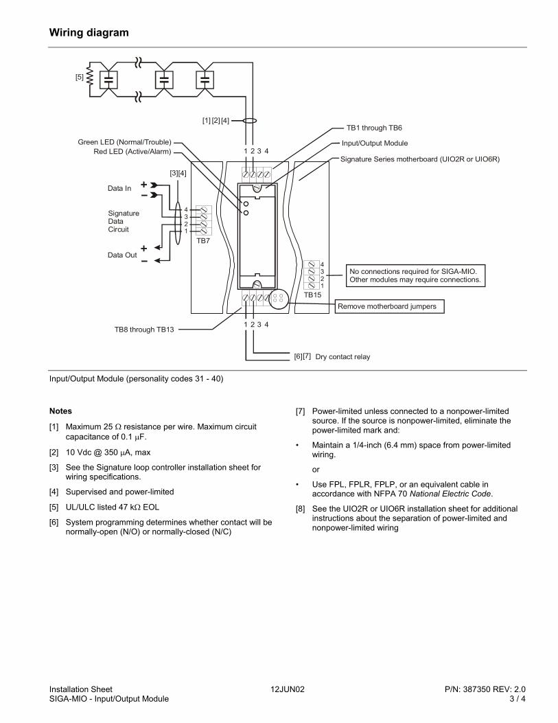
Installation Sheet 12JUN02 P/N: 387350 REV: 2.0SIGA-MIO - Input/Output Module 3 / 4
Wiring diagram
4321
TB15
1 2 3 4
Remove motherboard jumpers
1 2 3 4
[1] [4]
TB7
Green LED (Normal/Trouble)Red LED (Active/Alarm)
Data Out
SignatureDataCircuit
Data In
[3]
4321
No connections required for SIGA-MIO. Other modules may require connections.
Input/Output Module
Signature Series motherboard (UIO2R or UIO6R)
[5]
TB1 through TB6
TB8 through TB13
[2]
[4]
Dry contact relay[6][7]
Input/Output Module (personality codes 31 - 40)
Notes
[1] Maximum 25 resistance per wire. Maximum circuitcapacitance of 0.1 F.
[2] 10 Vdc @ 350 A, max
[3] See the Signature loop controller installation sheet forwiring specifications.
[4] Supervised and power-limited
[5] UL/ULC listed 47 k EOL
[6] System programming determines whether contact will benormally-open (N/O) or normally-closed (N/C)
[7] Power-limited unless connected to a nonpower-limitedsource. If the source is nonpower-limited, eliminate thepower-limited mark and:
• Maintain a 1/4-inch (6.4 mm) space from power-limitedwiring.
or
• Use FPL, FPLR, FPLP, or an equivalent cable inaccordance with NFPA 70 National Electric Code.
[8] See the UIO2R or UIO6R installation sheet for additionalinstructions about the separation of power-limited andnonpower-limited wiring

P/N: 387350 REV: 2.0 12JUN02 Installation Sheet4 / 4 SIGA-MIO - Input/Output Module
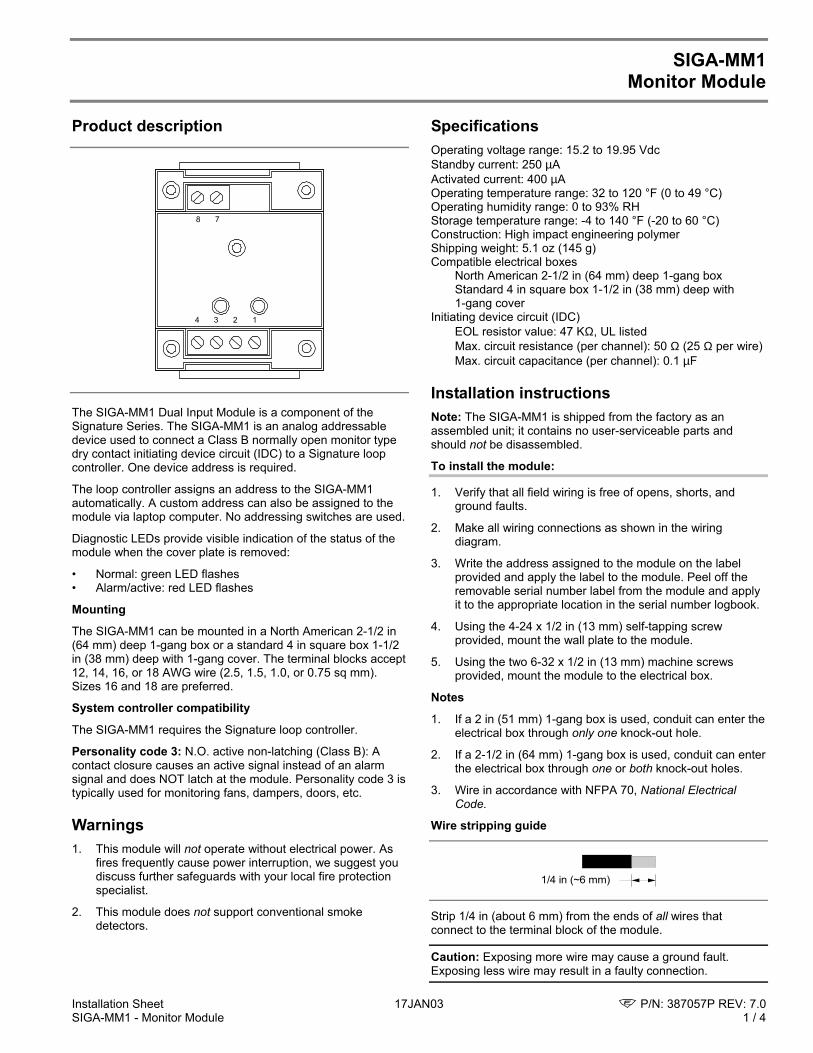
Installation Sheet 17JAN03 P/N: 387057P REV: 7.0SIGA-MM1 - Monitor Module 1 / 4
SIGA-MM1Monitor Module
Product description
1234
78
The SIGA-MM1 Dual Input Module is a component of theSignature Series. The SIGA-MM1 is an analog addressabledevice used to connect a Class B normally open monitor typedry contact initiating device circuit (IDC) to a Signature loopcontroller. One device address is required.
The loop controller assigns an address to the SIGA-MM1automatically. A custom address can also be assigned to themodule via laptop computer. No addressing switches are used.
Diagnostic LEDs provide visible indication of the status of themodule when the cover plate is removed:
• Normal: green LED flashes• Alarm/active: red LED flashes
Mounting
The SIGA-MM1 can be mounted in a North American 2-1/2 in(64 mm) deep 1-gang box or a standard 4 in square box 1-1/2in (38 mm) deep with 1-gang cover. The terminal blocks accept12, 14, 16, or 18 AWG wire (2.5, 1.5, 1.0, or 0.75 sq mm).Sizes 16 and 18 are preferred.
System controller compatibility
The SIGA-MM1 requires the Signature loop controller.
Personality code 3: N.O. active non-latching (Class B): Acontact closure causes an active signal instead of an alarmsignal and does NOT latch at the module. Personality code 3 istypically used for monitoring fans, dampers, doors, etc.
Warnings1. This module will not operate without electrical power. As
fires frequently cause power interruption, we suggest youdiscuss further safeguards with your local fire protectionspecialist.
2. This module does not support conventional smokedetectors.
SpecificationsOperating voltage range: 15.2 to 19.95 VdcStandby current: 250 µAActivated current: 400 µAOperating temperature range: 32 to 120 °F (0 to 49 °C)Operating humidity range: 0 to 93% RHStorage temperature range: -4 to 140 °F (-20 to 60 °C)Construction: High impact engineering polymerShipping weight: 5.1 oz (145 g)Compatible electrical boxes
North American 2-1/2 in (64 mm) deep 1-gang boxStandard 4 in square box 1-1/2 in (38 mm) deep with1-gang cover
Initiating device circuit (IDC)EOL resistor value: 47 KΩ, UL listedMax. circuit resistance (per channel): 50 Ω (25 Ω per wire)Max. circuit capacitance (per channel): 0.1 µF
Installation instructionsNote: The SIGA-MM1 is shipped from the factory as anassembled unit; it contains no user-serviceable parts andshould not be disassembled.
To install the module:
1. Verify that all field wiring is free of opens, shorts, andground faults.
2. Make all wiring connections as shown in the wiringdiagram.
3. Write the address assigned to the module on the labelprovided and apply the label to the module. Peel off theremovable serial number label from the module and applyit to the appropriate location in the serial number logbook.
4. Using the 4-24 x 1/2 in (13 mm) self-tapping screwprovided, mount the wall plate to the module.
5. Using the two 6-32 x 1/2 in (13 mm) machine screwsprovided, mount the module to the electrical box.
Notes
1. If a 2 in (51 mm) 1-gang box is used, conduit can enter theelectrical box through only one knock-out hole.
2. If a 2-1/2 in (64 mm) 1-gang box is used, conduit can enterthe electrical box through one or both knock-out holes.
3. Wire in accordance with NFPA 70, National ElectricalCode.
Wire stripping guide
1/4 in (~6 mm)
Strip 1/4 in (about 6 mm) from the ends of all wires thatconnect to the terminal block of the module.
Caution: Exposing more wire may cause a ground fault.Exposing less wire may result in a faulty connection.
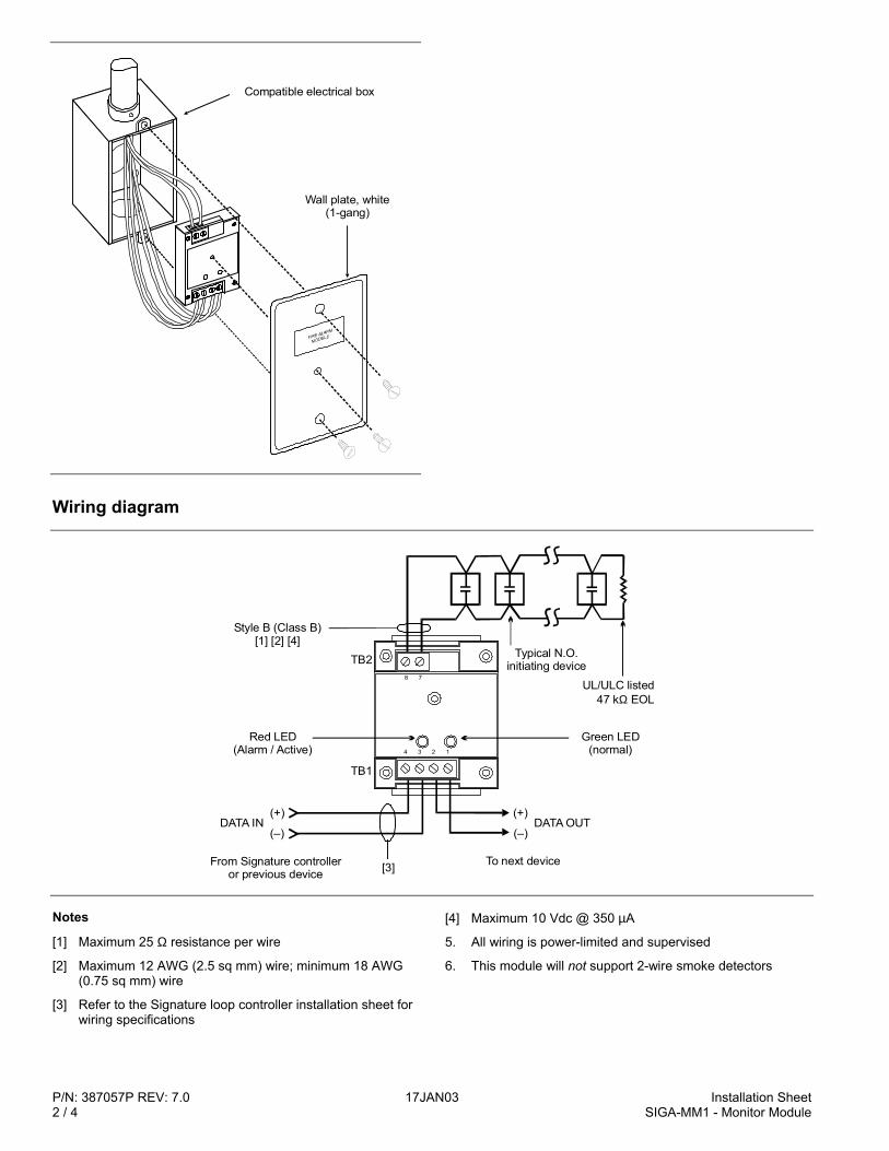
P/N: 387057P REV: 7.0 17JAN03 Installation Sheet2 / 4 SIGA-MM1 - Monitor Module
Compatible electrical box
Wall plate, white (1-gang)
Wiring diagram
(+)
(–)DATA OUT
Style B (Class B)[1] [2] [4]
Red LED(Alarm / Active)
TB2
TB1
Typical N.O.initiating device
UL/ULC listed47 k EOLΩ
Green LED(normal)
(+)
(–)
From Signature controlleror previous device [3] To next device
DATA IN
1234
78
Notes
[1] Maximum 25 Ω resistance per wire
[2] Maximum 12 AWG (2.5 sq mm) wire; minimum 18 AWG(0.75 sq mm) wire
[3] Refer to the Signature loop controller installation sheet forwiring specifications
[4] Maximum 10 Vdc @ 350 µA
5. All wiring is power-limited and supervised
6. This module will not support 2-wire smoke detectors
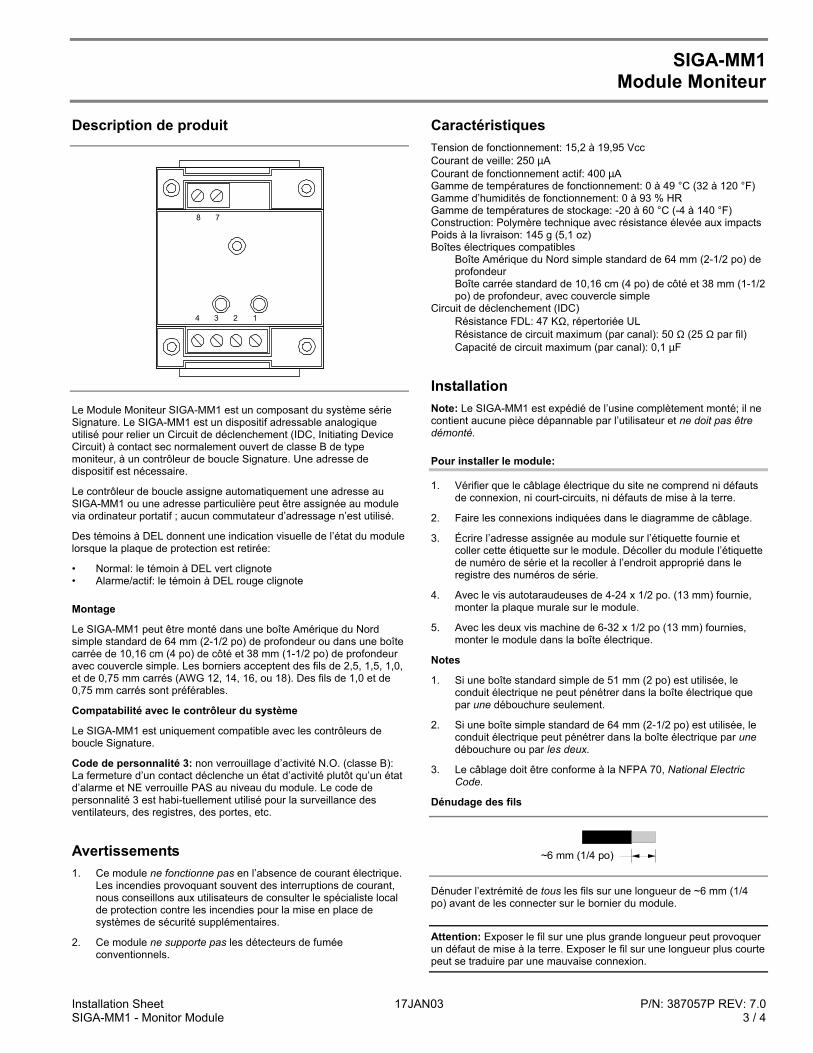
Installation Sheet 17JAN03 P/N: 387057P REV: 7.0SIGA-MM1 - Monitor Module 3 / 4
SIGA-MM1Module Moniteur
Description de produit
1234
78
Le Module Moniteur SIGA-MM1 est un composant du système sérieSignature. Le SIGA-MM1 est un dispositif adressable analogiqueutilisé pour relier un Circuit de déclenchement (IDC, Initiating DeviceCircuit) à contact sec normalement ouvert de classe B de typemoniteur, à un contrôleur de boucle Signature. Une adresse dedispositif est nécessaire.
Le contrôleur de boucle assigne automatiquement une adresse auSIGA-MM1 ou une adresse particulière peut être assignée au modulevia ordinateur portatif ; aucun commutateur d’adressage n’est utilisé.
Des témoins à DEL donnent une indication visuelle de l’état du modulelorsque la plaque de protection est retirée:
• Normal: le témoin à DEL vert clignote• Alarme/actif: le témoin à DEL rouge clignote
Montage
Le SIGA-MM1 peut être monté dans une boîte Amérique du Nordsimple standard de 64 mm (2-1/2 po) de profondeur ou dans une boîtecarrée de 10,16 cm (4 po) de côté et 38 mm (1-1/2 po) de profondeuravec couvercle simple. Les borniers acceptent des fils de 2,5, 1,5, 1,0,et de 0,75 mm carrés (AWG 12, 14, 16, ou 18). Des fils de 1,0 et de0,75 mm carrés sont préférables.
Compatabilité avec le contrôleur du système
Le SIGA-MM1 est uniquement compatible avec les contrôleurs deboucle Signature.
Code de personnalité 3: non verrouillage d’activité N.O. (classe B):La fermeture d’un contact déclenche un état d’activité plutôt qu’un étatd’alarme et NE verrouille PAS au niveau du module. Le code depersonnalité 3 est habi-tuellement utilisé pour la surveillance desventilateurs, des registres, des portes, etc.
Avertissements1. Ce module ne fonctionne pas en l’absence de courant électrique.
Les incendies provoquant souvent des interruptions de courant,nous conseillons aux utilisateurs de consulter le spécialiste localde protection contre les incendies pour la mise en place desystèmes de sécurité supplémentaires.
2. Ce module ne supporte pas les détecteurs de fuméeconventionnels.
CaractéristiquesTension de fonctionnement: 15,2 à 19,95 VccCourant de veille: 250 µACourant de fonctionnement actif: 400 µAGamme de températures de fonctionnement: 0 à 49 °C (32 à 120 °F)Gamme d’humidités de fonctionnement: 0 à 93 % HRGamme de températures de stockage: -20 à 60 °C (-4 à 140 °F)Construction: Polymère technique avec résistance élevée aux impactsPoids à la livraison: 145 g (5,1 oz)Boîtes électriques compatibles
Boîte Amérique du Nord simple standard de 64 mm (2-1/2 po) deprofondeurBoîte carrée standard de 10,16 cm (4 po) de côté et 38 mm (1-1/2po) de profondeur, avec couvercle simple
Circuit de déclenchement (IDC)Résistance FDL: 47 KΩ, répertoriée ULRésistance de circuit maximum (par canal): 50 Ω (25 Ω par fil)Capacité de circuit maximum (par canal): 0,1 µF
InstallationNote: Le SIGA-MM1 est expédié de l’usine complètement monté; il necontient aucune pièce dépannable par l’utilisateur et ne doit pas êtredémonté.
Pour installer le module:
1. Vérifier que le câblage électrique du site ne comprend ni défautsde connexion, ni court-circuits, ni défauts de mise à la terre.
2. Faire les connexions indiquées dans le diagramme de câblage.
3. Écrire l’adresse assignée au module sur l’étiquette fournie etcoller cette étiquette sur le module. Décoller du module l’étiquettede numéro de série et la recoller à l’endroit approprié dans leregistre des numéros de série.
4. Avec le vis autotaraudeuses de 4-24 x 1/2 po. (13 mm) fournie,monter la plaque murale sur le module.
5. Avec les deux vis machine de 6-32 x 1/2 po (13 mm) fournies,monter le module dans la boîte électrique.
Notes
1. Si une boîte standard simple de 51 mm (2 po) est utilisée, leconduit électrique ne peut pénétrer dans la boîte électrique quepar une débouchure seulement.
2. Si une boîte simple standard de 64 mm (2-1/2 po) est utilisée, leconduit électrique peut pénétrer dans la boîte électrique par unedébouchure ou par les deux.
3. Le câblage doit être conforme à la NFPA 70, National ElectricCode.
Dénudage des fils
~6 mm 1/4 po ( )
Dénuder l’extrémité de tous les fils sur une longueur de ~6 mm (1/4po) avant de les connecter sur le bornier du module.
Attention: Exposer le fil sur une plus grande longueur peut provoquerun défaut de mise à la terre. Exposer le fil sur une longueur plus courtepeut se traduire par une mauvaise connexion.
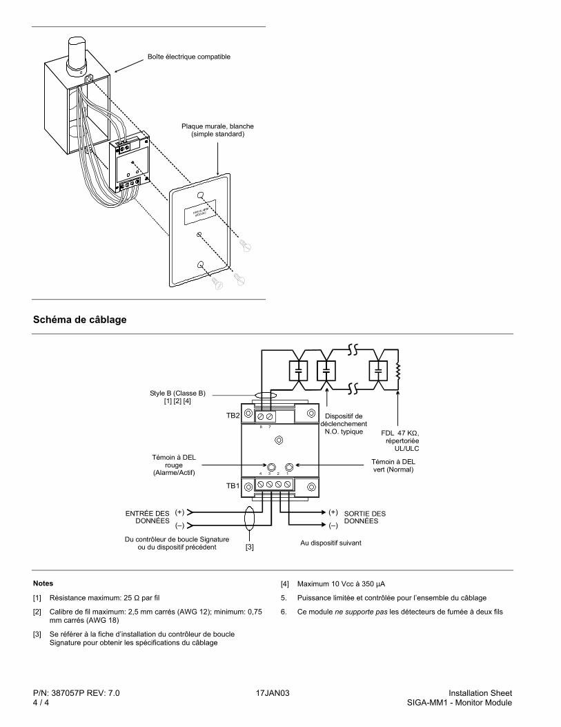
P/N: 387057P REV: 7.0 17JAN03 Installation Sheet4 / 4 SIGA-MM1 - Monitor Module
Boîte électrique compatible
Plaque murale, blanche (simple standard)
Schéma de câblage
(+)
(–)
TB2
TB1
(+)
(–)
[3]
1234
78
Au dispositif suivantDu contrôleur de boucle Signature ou du dispositif précédent
Témoin à DEL vert (Normal)
FDL 47 K , répertoriée
UL/ULC
Ω
ENTRÉE DES DONNÉES
Témoin à DEL rouge
(Alarme/Actif)
SORTIE DES DONNÉES
Style B (Classe B)[1] [2] [4]
Dispositif dedéclenchement
N.O. typique
Notes
[1] Résistance maximum: 25 Ω par fil
[2] Calibre de fil maximum: 2,5 mm carrés (AWG 12); minimum: 0,75mm carrés (AWG 18)
[3] Se référer à la fiche d’installation du contrôleur de boucleSignature pour obtenir les spécifications du câblage
[4] Maximum 10 Vcc à 350 µA
5. Puissance limitée et contrôlée pour l’ensemble du câblage
6. Ce module ne supporte pas les détecteurs de fumée à deux fils
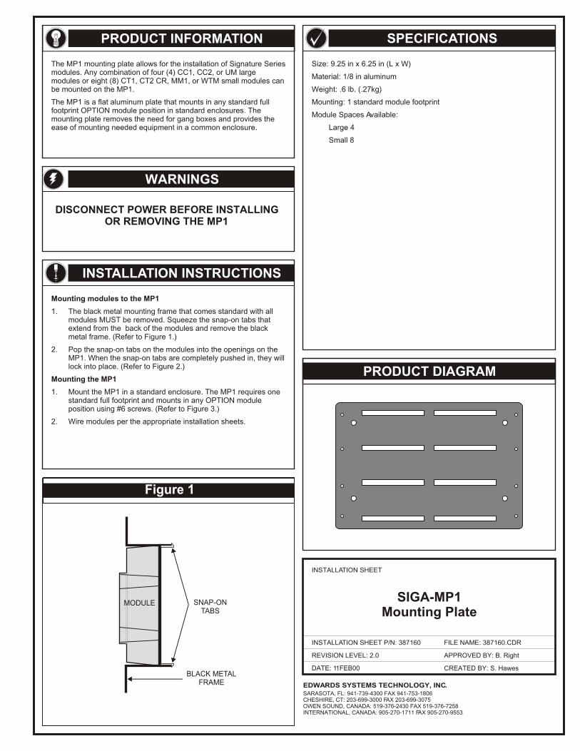
Figure 1
MODULE SNAP-ONTABS
BLACK METALFRAME
WARNINGS
Mounting modules to the MP1
1. The black metal mounting frame that comes standard with all modules MUST be removed. Squeeze the snap-on tabs that extend from the back of the modules and remove the black metal frame. (Refer to Figure 1.)
2. Pop the snap-on tabs on the modules into the openings on the MP1. When the snap-on tabs are completely pushed in, they will lock into place. (Refer to Figure 2.)
Mounting the MP1
1. Mount the MP1 in a standard enclosure. The MP1 requires one standard full footprint and mounts in any OPTION module position using #6 screws.
2. Wire modules per the appropriate installation sheets.
(Refer to Figure 3.)
DISCONNECT POWER BEFORE INSTALLINGOR REMOVING THE MP1
The MP1 mounting plate allows for the installation of Signature Series modules. Any combination of four (4) CC1, CC2, or UM large modules or eight (8) CT1, CT2 CR, MM1, or WTM small modules can be mounted on the MP1.
The MP1 is a flat aluminum plate that mounts in any standard full footprint OPTION module position in standard enclosures. The mounting plate removes the need for gang boxes and provides the ease of mounting needed equipment in a common enclosure.
Size: 9.25 in x 6.25 in (L x W)
Material: 1/8 in aluminum
Weight: .6 lb. (.27kg)
Mounting: 1 standard module footprint
Module Spaces Available:
Large 4
Small 8
PRODUCT INFORMATION
PRODUCT DIAGRAM
SPECIFICATIONS
DATE: 11FEB00
INSTALLATION SHEET
INSTALLATION SHEET P/N: 387160
REVISION LEVEL: 2.0
FILE NAME: 387160.CDR
CREATED BY: S. Hawes
APPROVED BY: B. Right
EDWARDS SYSTEMS TECHNOLOGY, INC.SARASOTA, FL: 941-739-4300 FAX 941-753-1806CHESHIRE, CT: 203-699-3000 FAX 203-699-3075OWEN SOUND, CANADA: 519-376-2430 FAX 519-376-7258INTERNATIONAL, CANADA: 905-270-1711 FAX 905-270-9553
INSTALLATION INSTRUCTIONS
SIGA-MP1Mounting Plate
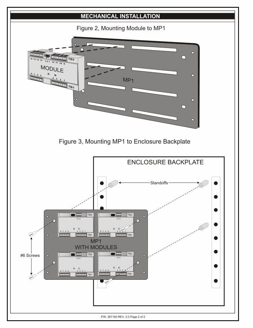
Figure 3, Mounting MP1 to Enclosure Backplate
ENCLOSURE BACKPLATE
MP1WITH MODULES
48 37 26
10
15
9
TB1
TB3
48 37 26
10
15
9
TB1
TB3
48 37 26
10
15
9
TB1
TB3
48 37 26
10
15
9
TB1
TB3#6 Screws
Standoffs
MP1
MODULE
MECHANICAL INSTALLATION
Figure 2, Mounting Module to MP1
P/N: 387160 REV: 2.0 Page 2 of 2
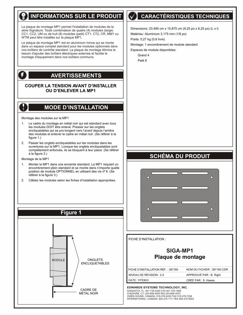
Figure 1
MODULE
La plaque de montage MP1 permet l'installation de modules de la série Signature. Toute combinaison de quatre (4) modules (large) CC1, CC2, UM ou de huit (8) modules (petit) CT1, CT2, CR, MM1 ou WTM peut être installés sur la plaque MP1.
Le plaque de montage MP1 est en aluminium mince qui se monte dans un espace complet standard pour les modules optionnels dans nos boîtiers de contrôle standard. La plaque de montage élimine le besoin d'ajouter des boîtiers électriques externes et facilite le montage d'équipement dans nos boîtiers communs.
DATE: 11FEB00
EDWARDS SYSTEMS TECHNOLOGY, INC.SARASOTA, FL: 941-739-4300 FAX 941-753-1806CHESHIRE, CT: 203-699-3000 FAX 203-699-3075OWEN SOUND, CANADA: 519-376-2430 FAX 519-376-7258INTERNATIONAL, CANADA: 905-270-1711 FAX 905-270-9553
INFORMATIONS SUR LE PRODUIT
AVERTISSEMENTS
COUPER LA TENSION AVANT D’INSTALLEROU D’ENLEVER LA MP1
MODE D’INSTALLATION
Montage des modules sur la MP1
1. Le cadre du montage en métal noir qui est standard avec tous les modules DOIT être enlevé. Presser sur les onglets encliquetables qui se pro-longent vers l’avant depuis l’arrière des modules et enlever le cadre en métal noir. (Se référer à la figure 1.)
2. Passer les onglets encliquetables sur les modules dans les ouvertures sur la MP1. Lorsque les onglets encliquetables sont complètement enfoncés, ils se bloquent à leur place. (Se référer à la figure 2.)
Montage de la MP1
1. Monter la MP1 dans une enceinte standard. La MP1 requiert un encombrement plein standard et se monte dans n’importe quelle position de module OPTIONNEL en utilisant des vis n⁰ 6. (Se référer à la figure 3.)
2. Câblez les modules selon les fiches d’installation appropriées.
CARACTÉRISTIQUES TECHNIQUES
Dimensions: 23,495 cm x 15,875 cm (9,25 po x 6,25 po) (L x l)
Matériau: Aluminium 3,175 mm (1/8 po)
Poids: 0,27 kg (0,6 livre)
Montage: 1 encombrement de module standard
Espaces de module disponibles:
Grand 4
Petit 8
SCHÉMA DU PRODUIT
FICHE D’INSTALLATION :
SIGA-MP1Plaque de montage
FICHE D’INSTALLATION RÉF. : 387160 NOM DU FICHIER : 387160.CDR
NIVEAU DE RÉVISION : 2.0
CRÉÉ PAR : S. Hawes
APPROUVÉ PAR : B. Right
ONGLETSENCLIQUETABLES
CADRE DEMÉTAL NOIR
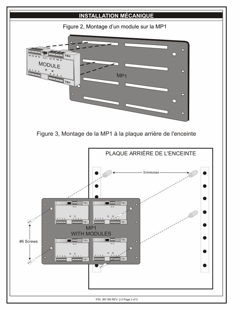
P/N: 387160 REV: 2.0 Page 2 of 2
INSTALLATION MÉCANIQUE
Figure 2, Montage d’un module sur la MP1
MP1
MODULE
Figure 3, Montage de la MP1 à la plaque arrière de l'enceinte
PLAQUE ARRIÈRE DE L'ENCEINTE
MP1WITH MODULES
48 37 26
10
15
9
TB1
TB3
48 37 26
10
15
9
TB1
TB3
48 37 26
10
15
9
TB1
TB3
48 37 26
10
15
9
TB1
TB3#6 Screws
Entretoises
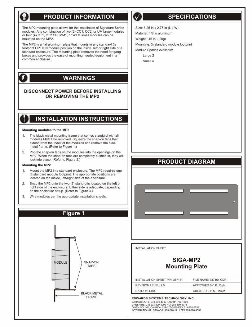
Figure 1
MODULE SNAP-ONTABS
BLACK METALFRAME
WARNINGS
Mounting modules to the MP2
1. The black metal mounting frame that comes standard with all modules MUST be removed. Squeeze the snap-on tabs that extend from the back of the modules and remove the black metal frame. (Refer to Figure 1.)
2. Pop the snap-on tabs on the modules into the openings on the MP2. When the snap-on tabs are completely pushed in, they will lock into place. (Refer to Figure 2.)
Mounting the MP2
1. Mount the MP2 in a standard enclosure. The MP2 requires one ½ standard module footprint. The appropriate positions are located on the inside, left/right side of the enclosure.
2. Snap the MP2 onto the two (2) stand-offs located on the left or right side of the enclosure. Either side is adequate, depending on the enclosure setup. (Refer to Figure 3.)
3. Wire modules per the appropriate installation sheets.
DISCONNECT POWER BEFORE INSTALLINGOR REMOVING THE MP2
The MP2 mounting plate allows for the installation of Signature Series modules. Any combination of two (2) CC1, CC2, or UM large modules or four (4) CT1, CT2 CR, MM1, or WTM small modules can be mounted on the MP2.
The MP2 is a flat aluminum plate that mounts in any standard ½ footprint OPTION module position on the inside, left or right side of a standard enclosure. The mounting plate removes the need for gang boxes and provides the ease of mounting needed equipment in a common enclosure.
Size: 8.25 in x 2.75 in (L x W)
Material: 1/8 in aluminum
Weight: .45 lb. (.2kg)
Mounting: ½ standard module footprint
Module Spaces Available:
Large 2
Small 4
PRODUCT INFORMATION
PRODUCT DIAGRAM
SPECIFICATIONS
DATE: 11FEB00
INSTALLATION SHEET
INSTALLATION SHEET P/N: 387161
REVISION LEVEL: 2.0
FILE NAME: 387161.CDR
CREATED BY: S. Hawes
APPROVED BY: B. Right
EDWARDS SYSTEMS TECHNOLOGY, INC.SARASOTA, FL: 941-739-4300 FAX 941-753-1806CHESHIRE, CT: 203-699-3000 FAX 203-699-3075OWEN SOUND, CANADA: 519-376-2430 FAX 519-376-7258INTERNATIONAL, CANADA: 905-270-1711 FAX 905-270-9553
INSTALLATION INSTRUCTIONS
SIGA-MP2Mounting Plate
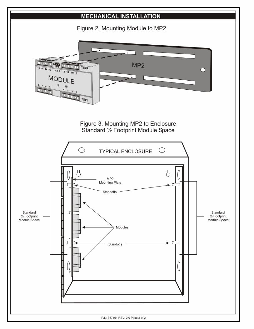
MP2
MODULE
MECHANICAL INSTALLATION
Figure 2, Mounting Module to MP2
Figure 3, Mounting MP2 to EnclosureStandard ½ Footprint Module Space
MP2Mounting Plate
Modules
Standard½ Footprint
Module Space
Standard½ Footprint
Module Space
Standoffs
Standoffs
TYPICAL ENCLOSURE
P/N: 387161 REV: 2.0 Page 2 of 2
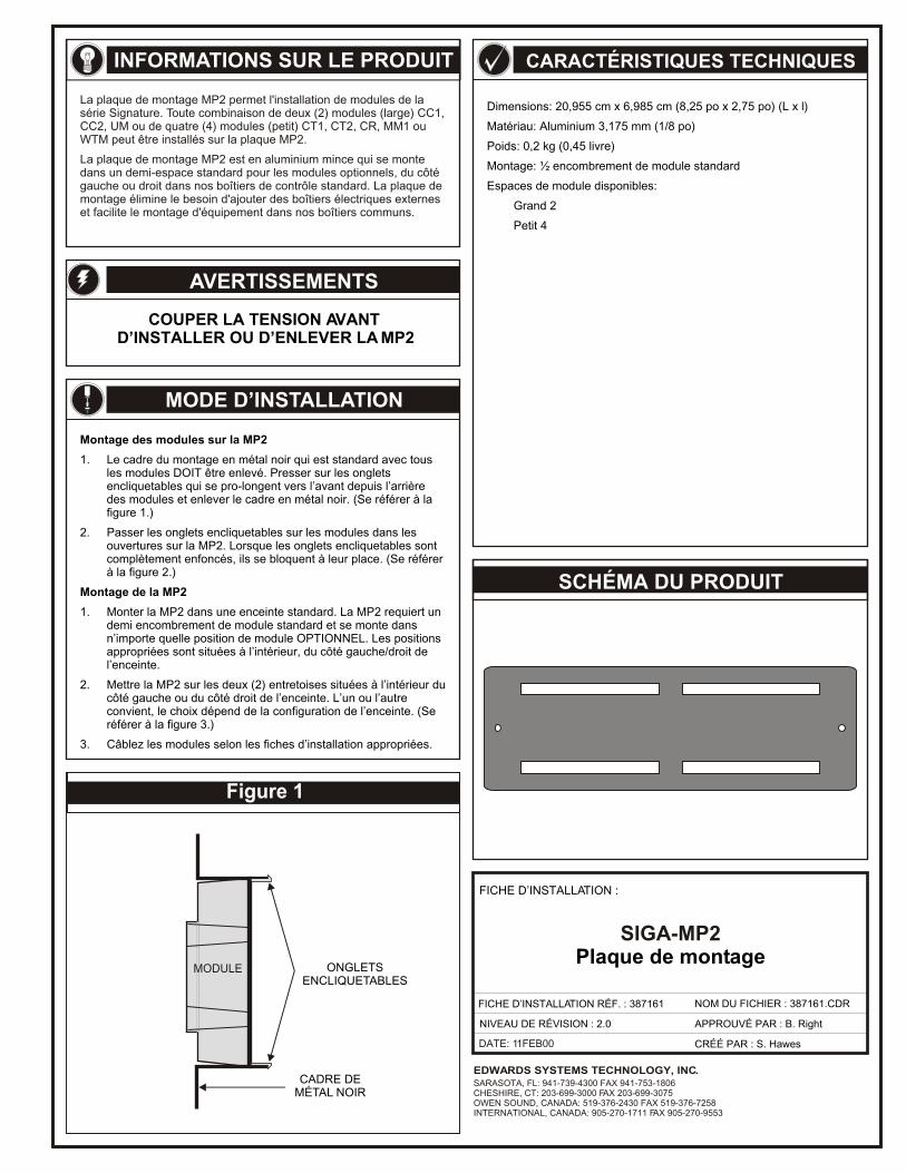
Figure 1
MODULE
La plaque de montage MP2 permet l'installation de modules de la série Signature. Toute combinaison de deux (2) modules (large) CC1, CC2, UM ou de quatre (4) modules (petit) CT1, CT2, CR, MM1 ou WTM peut être installés sur la plaque MP2.
La plaque de montage MP2 est en aluminium mince qui se monte dans un demi-espace standard pour les modules optionnels, du côté gauche ou droit dans nos boîtiers de contrôle standard. La plaque de montage élimine le besoin d'ajouter des boîtiers électriques externes et facilite le montage d'équipement dans nos boîtiers communs.
DATE: 11FEB00
EDWARDS SYSTEMS TECHNOLOGY, INC.SARASOTA, FL: 941-739-4300 FAX 941-753-1806CHESHIRE, CT: 203-699-3000 FAX 203-699-3075OWEN SOUND, CANADA: 519-376-2430 FAX 519-376-7258INTERNATIONAL, CANADA: 905-270-1711 FAX 905-270-9553
INFORMATIONS SUR LE PRODUIT
AVERTISSEMENTS
COUPER LA TENSION AVANT D’INSTALLER OU D’ENLEVER LA MP2
MODE D’INSTALLATION
Montage des modules sur la MP2
1. Le cadre du montage en métal noir qui est standard avec tous les modules DOIT être enlevé. Presser sur les onglets encliquetables qui se pro-longent vers l’avant depuis l’arrière des modules et enlever le cadre en métal noir. (Se référer à la figure 1.)
2. Passer les onglets encliquetables sur les modules dans les ouvertures sur la MP2. Lorsque les onglets encliquetables sont complètement enfoncés, ils se bloquent à leur place. (Se référer à la figure 2.)
Montage de la MP2
1. Monter la MP2 dans une enceinte standard. La MP2 requiert un demi encombrement de module standard et se monte dans n’importe quelle position de module OPTIONNEL. Les positions appropriées sont situées à l’intérieur, du côté gauche/droit de l’enceinte.
2. Mettre la MP2 sur les deux (2) entretoises situées à l’intérieur du côté gauche ou du côté droit de l’enceinte. L’un ou l’autre convient, le choix dépend de la configuration de l’enceinte. (Se référer à la figure 3.)
3. Câblez les modules selon les fiches d’installation appropriées.
CARACTÉRISTIQUES TECHNIQUES
Dimensions: 20,955 cm x 6,985 cm (8,25 po x 2,75 po) (L x l)
Matériau: Aluminium 3,175 mm (1/8 po)
Poids: 0,2 kg (0,45 livre)
Montage: ½ encombrement de module standard
Espaces de module disponibles:
Grand 2
Petit 4
SCHÉMA DU PRODUIT
FICHE D’INSTALLATION :
SIGA-MP2Plaque de montage
FICHE D’INSTALLATION RÉF. : 387161 NOM DU FICHIER : 387161.CDR
NIVEAU DE RÉVISION : 2.0
CRÉÉ PAR : S. Hawes
APPROUVÉ PAR : B. Right
ONGLETSENCLIQUETABLES
CADRE DEMÉTAL NOIR
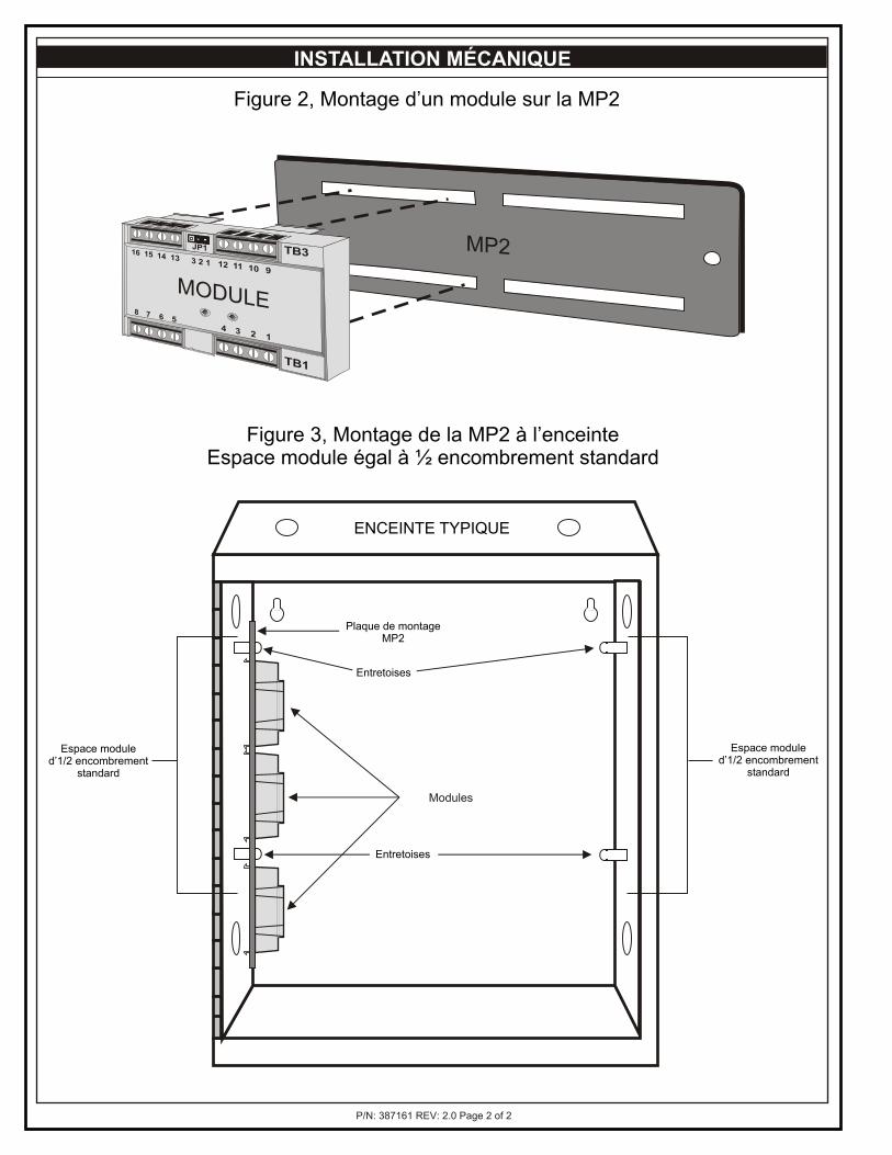
MP2
MODULE
P/N: 387161 REV: 2.0 Page 2 of 2
Plaque de montageMP2
Modules
Espace moduled’1/2 encombrement
standard
Espace moduled’1/2 encombrement
standard
Entretoises
Entretoises
ENCEINTE TYPIQUE
INSTALLATION MÉCANIQUE
Figure 2, Montage d’un module sur la MP2
Figure 3, Montage de la MP2 à l’enceinteEspace module égal à ½ encombrement standard
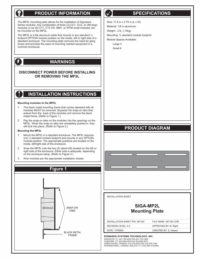
Figure 1
MODULE SNAP-ONTABS
BLACK METALFRAME
WARNINGS
Mounting modules to the MP2L
Mounting the MP2L
1. The black metal mounting frame that comes standard with allmodules MUST be removed. Squeeze the snap-on tabs thatextend from the back of the modules and remove the blackmetal frame. (Refer to Figure 1.)
2. Pop the snap-on tabs on the modules into the openings on theMP2L. When the snap-on tabs are completely pushed in, theywill lock into place. (Refer to Figure 2.)
1. Mount the MP2L in a standard enclosure. The MP2L requiresone ½ standard module footprint and mounts in any OPTIONmodule position. The appropriate positions are located on theinside, left/right side of the enclosure.
2. Snap the MP2L onto the two (2) stand-offs located on the left orright side of the enclosure. Either side is adequate, dependingon the enclosure setup. (Refer to Figure 3.)
3. Wire modules per the appropriate installation sheets.
DISCONNECT POWER BEFORE INSTALLINGOR REMOVING THE MP2L
The MP2L mounting plate allows for the installation of SignatureSeries modules. Any combination of three (3) CC1, CC2, or UM largemodules or six (6) CT1, CT2 CR, MM1, or WTM small modules canbe mounted on the MP2L.
The MP2L is a flat aluminum plate that mounts in any standard ½footprint OPTION module position on the inside, left or right side of astandard enclosure. The mounting plate removes the need for gangboxes and provides the ease of mounting needed equipment in acommon enclosure.
Size: 11.8 in x 2.75 in (L x W)
Material: 1/8 in aluminum
Weight: .3 lb. (.14kg)
Mounting: ½ standard module footprint
Module Spaces Available:
Large 3
Small 6
PRODUCT INFORMATION
PRODUCT DIAGRAM
SPECIFICATIONS
DATE: 11FEB00
INSTALLATION SHEET
INSTALLATION SHEET P/N: 387162
REVISION LEVEL: 2.0
FILE NAME: 387162.CDR
CREATED BY: S. Hawes
APPROVED BY: B. Right
EDWARDS SYSTEMS TECHNOLOGY, INC.SARASOTA, FL: 941-739-4300 FAX 941-753-1806CHESHIRE, CT: 203-699-3000 FAX 203-699-3075OWEN SOUND, CANADA: 519-376-2430 FAX 519-376-7258INTERNATIONAL, CANADA: 905-270-1711 FAX 905-270-9553
INSTALLATION INSTRUCTIONS
SIGA-MP2LMounting Plate
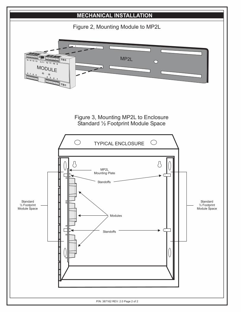
MECHANICAL INSTALLATION
Figure 2, Mounting Module to MP2L
Figure 3, Mounting MP2L to EnclosureStandard ½ Footprint Module Space
MP2L
MODULE
MP2LMounting Plate
Modules
Standard½ Footprint
Module Space
Standard½ Footprint
Module Space
Standoffs
Standoffs
TYPICAL ENCLOSURE
P/N: 387162 REV: 2.0 Page 2 of 2
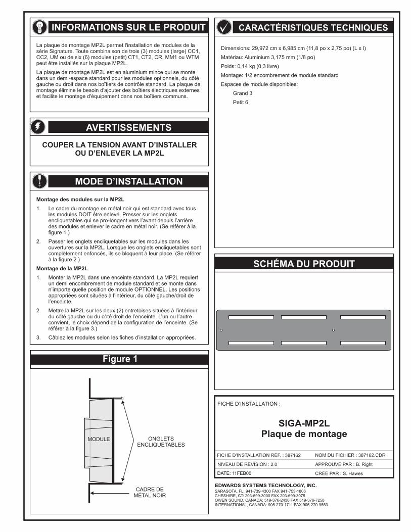
Figure 1
MODULE
DATE: 11FEB00
EDWARDS SYSTEMS TECHNOLOGY, INC.SARASOTA, FL: 941-739-4300 FAX 941-753-1806CHESHIRE, CT: 203-699-3000 FAX 203-699-3075OWEN SOUND, CANADA: 519-376-2430 FAX 519-376-7258INTERNATIONAL, CANADA: 905-270-1711 FAX 905-270-9553
INFORMATIONS SUR LE PRODUIT
AVERTISSEMENTS
COUPER LA TENSION AVANT D’INSTALLEROU D’ENLEVER LA MP2L
MODE D’INSTALLATION
Montage des modules sur la MP2L
Montage de la MP2L
1. Le cadre du montage en métal noir qui est standard avec tousles modules DOIT être enlevé. Presser sur les ongletsencliquetables qui se pro-longent vers l’avant depuis l’arrièredes modules et enlever le cadre en métal noir. (Se référer à lafigure 1.)
2. Passer les onglets encliquetables sur les modules dans lesouvertures sur la MP2L. Lorsque les onglets encliquetables sontcomplètement enfoncés, ils se bloquent à leur place. (Se référerà la figure 2.)
1. Monter la MP2L dans une enceinte standard. La MP2L requiertun demi encombrement de module standard et se monte dansn’importe quelle position de module OPTIONNEL. Les positionsappropriées sont situées à l’intérieur, du côté gauche/droit del’enceinte.
2. Mettre la MP2L sur les deux (2) entretoises situées à l’intérieurdu côté gauche ou du côté droit de l’enceinte. L’un ou l’autreconvient, le choix dépend de la configuration de l’enceinte. (Seréférer à la figure 3.)
3. Câblez les modules selon les fiches d’installation appropriées.
CARACTÉRISTIQUES TECHNIQUES
Dimensions: 29,972 cm x 6,985 cm (11,8 po x 2,75 po) (L x l)
Matériau: Aluminium 3,175 mm (1/8 po)
Poids: 0,14 kg (0,3 livre)
Montage: 1/2 encombrement de module standard
Espaces de module disponibles:
Grand 3
Petit 6
SCHÉMA DU PRODUIT
FICHE D’INSTALLATION :
SIGA-MP2LPlaque de montage
FICHE D’INSTALLATION RÉF. : 387162 NOM DU FICHIER : 387162.CDR
NIVEAU DE RÉVISION : 2.0
CRÉÉ PAR : S. Hawes
APPROUVÉ PAR : B. Right
ONGLETSENCLIQUETABLES
CADRE DEMÉTAL NOIR
La plaque de montage MP2L permet l'installation de modules de lasérie Signature. Toute combinaison de (3) modules (large) CC1,CC2, UM ou de (6) modules (petit) CT1, CT2, CR, MM1 ou WTMpeut être installés sur la plaque MP2L.
La plaque demontage élimine le besoin d'ajouter des boîtiers électriques externeset facilite le montage d'équipement dans nos boîtiers communs.
La plaque de montage MP2L est en aluminium mince qui se montedans un demi-espace standard pour les modules optionnels, du côtégauche ou droit dans nos boîtiers de contrôle standard.
troissix
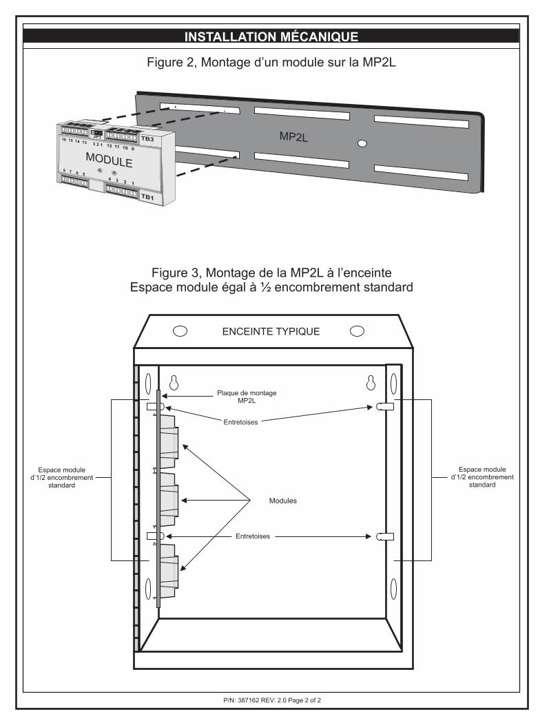
MP2L
MODULE
P/N: 387162 REV: 2.0 Page 2 of 2
Plaque de montageMP2L
Modules
Espace moduled’1/2 encombrement
standard
Espace moduled’1/2 encombrement
standard
Entretoises
Entretoises
ENCEINTE TYPIQUE
INSTALLATION MÉCANIQUE
Figure 2, Montage d’un module sur la MP2L
Figure 3, Montage de la MP2L à l’enceinteEspace module égal à ½ encombrement standard
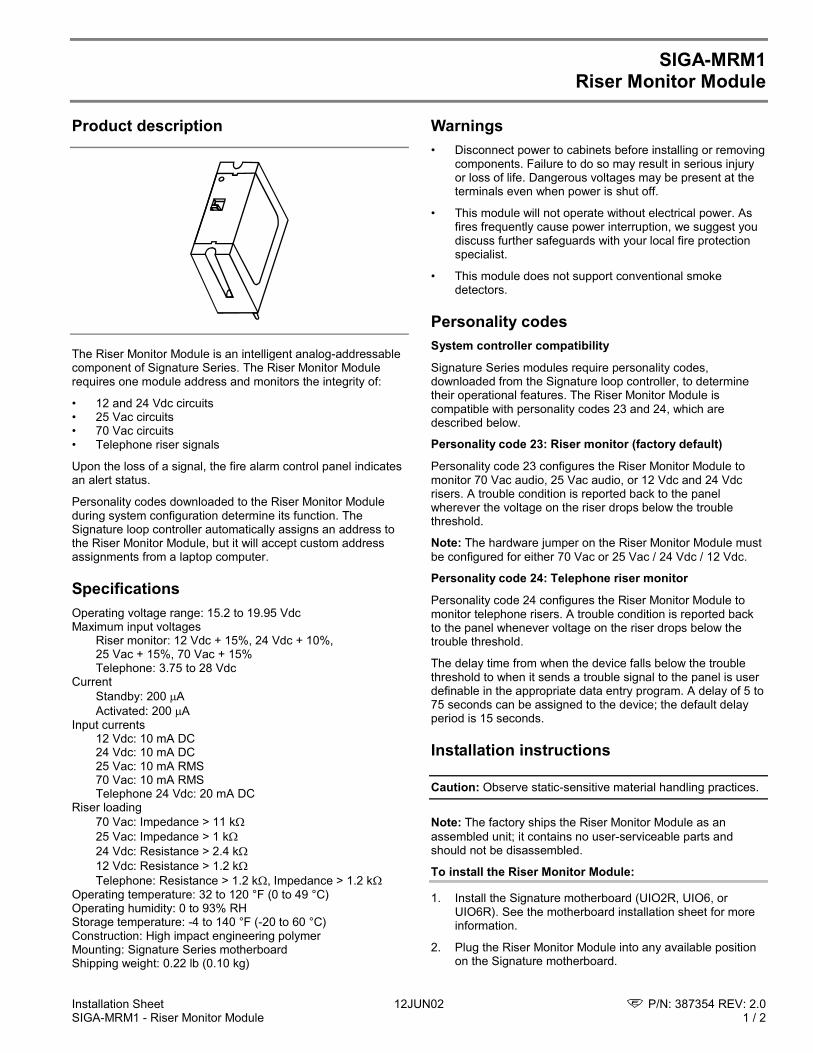
Installation Sheet 12JUN02 P/N: 387354 REV: 2.0SIGA-MRM1 - Riser Monitor Module 1 / 2
SIGA-MRM1Riser Monitor Module
Product description
The Riser Monitor Module is an intelligent analog-addressablecomponent of Signature Series. The Riser Monitor Modulerequires one module address and monitors the integrity of:
• 12 and 24 Vdc circuits• 25 Vac circuits• 70 Vac circuits• Telephone riser signals
Upon the loss of a signal, the fire alarm control panel indicatesan alert status.
Personality codes downloaded to the Riser Monitor Moduleduring system configuration determine its function. TheSignature loop controller automatically assigns an address tothe Riser Monitor Module, but it will accept custom addressassignments from a laptop computer.
SpecificationsOperating voltage range: 15.2 to 19.95 VdcMaximum input voltages
Riser monitor: 12 Vdc + 15%, 24 Vdc + 10%,25 Vac + 15%, 70 Vac + 15%Telephone: 3.75 to 28 Vdc
CurrentStandby: 200 AActivated: 200 A
Input currents12 Vdc: 10 mA DC24 Vdc: 10 mA DC25 Vac: 10 mA RMS70 Vac: 10 mA RMSTelephone 24 Vdc: 20 mA DC
Riser loading70 Vac: Impedance > 11 k25 Vac: Impedance > 1 k24 Vdc: Resistance > 2.4 k12 Vdc: Resistance > 1.2 kTelephone: Resistance > 1.2 k, Impedance > 1.2 k
Operating temperature: 32 to 120 °F (0 to 49 °C)Operating humidity: 0 to 93% RHStorage temperature: -4 to 140 °F (-20 to 60 °C)Construction: High impact engineering polymerMounting: Signature Series motherboardShipping weight: 0.22 lb (0.10 kg)
Warnings• Disconnect power to cabinets before installing or removing
components. Failure to do so may result in serious injuryor loss of life. Dangerous voltages may be present at theterminals even when power is shut off.
• This module will not operate without electrical power. Asfires frequently cause power interruption, we suggest youdiscuss further safeguards with your local fire protectionspecialist.
• This module does not support conventional smokedetectors.
Personality codesSystem controller compatibility
Signature Series modules require personality codes,downloaded from the Signature loop controller, to determinetheir operational features. The Riser Monitor Module iscompatible with personality codes 23 and 24, which aredescribed below.
Personality code 23: Riser monitor (factory default)
Personality code 23 configures the Riser Monitor Module tomonitor 70 Vac audio, 25 Vac audio, or 12 Vdc and 24 Vdcrisers. A trouble condition is reported back to the panelwherever the voltage on the riser drops below the troublethreshold.
Note: The hardware jumper on the Riser Monitor Module mustbe configured for either 70 Vac or 25 Vac / 24 Vdc / 12 Vdc.
Personality code 24: Telephone riser monitor
Personality code 24 configures the Riser Monitor Module tomonitor telephone risers. A trouble condition is reported backto the panel whenever voltage on the riser drops below thetrouble threshold.
The delay time from when the device falls below the troublethreshold to when it sends a trouble signal to the panel is userdefinable in the appropriate data entry program. A delay of 5 to75 seconds can be assigned to the device; the default delayperiod is 15 seconds.
Installation instructions
Caution: Observe static-sensitive material handling practices.
Note: The factory ships the Riser Monitor Module as anassembled unit; it contains no user-serviceable parts andshould not be disassembled.
To install the Riser Monitor Module:
1. Install the Signature motherboard (UIO2R, UIO6, orUIO6R). See the motherboard installation sheet for moreinformation.
2. Plug the Riser Monitor Module into any available positionon the Signature motherboard.
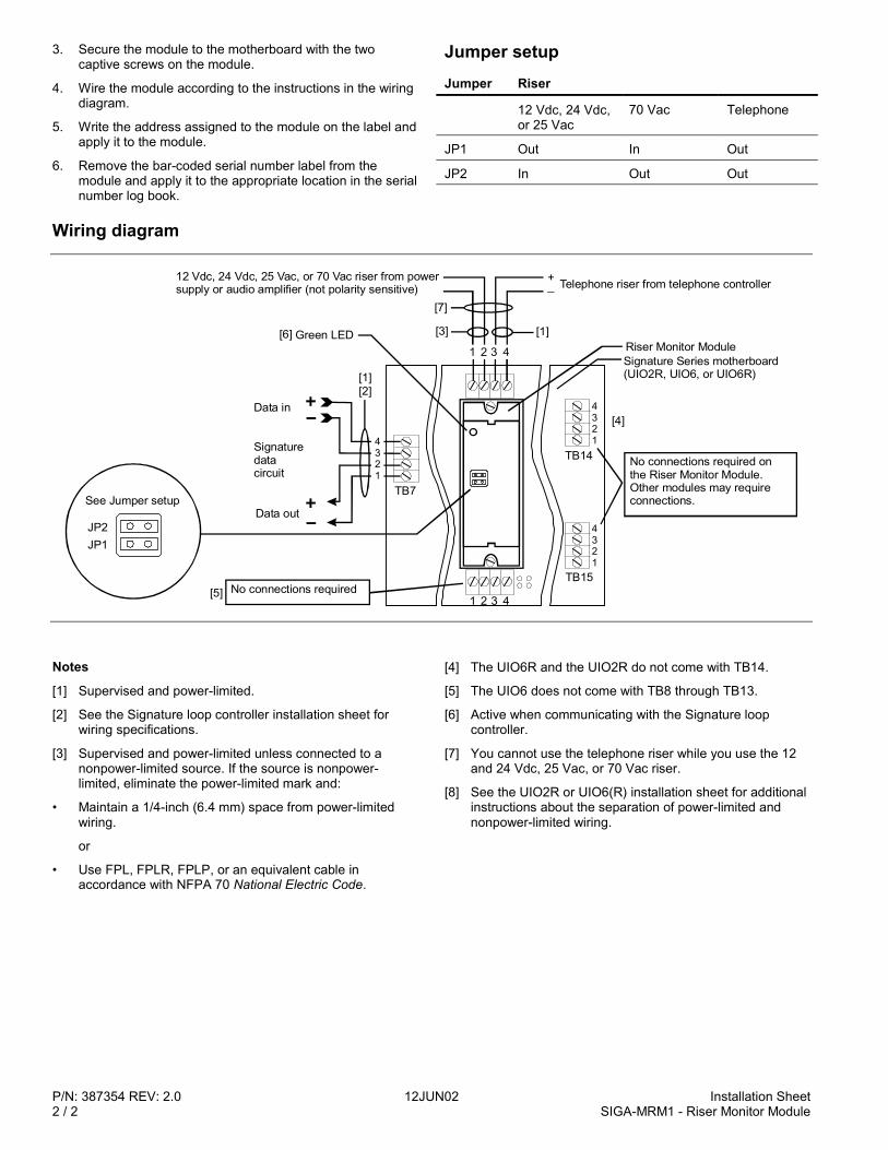
P/N: 387354 REV: 2.0 12JUN02 Installation Sheet2 / 2 SIGA-MRM1 - Riser Monitor Module
3. Secure the module to the motherboard with the twocaptive screws on the module.
4. Wire the module according to the instructions in the wiringdiagram.
5. Write the address assigned to the module on the label andapply it to the module.
6. Remove the bar-coded serial number label from themodule and apply it to the appropriate location in the serialnumber log book.
Jumper setupJumper Riser
12 Vdc, 24 Vdc,or 25 Vac
70 Vac Telephone
JP1 Out In Out
JP2 In Out Out
Wiring diagram
4321
4321
TB14
TB15No connections required
1 2 3 4
[4]
[5]
1 2 3 4
[3]
TB7
Green LED
Data out
Signaturedatacircuit
Data in[2]
4321
No connections required on the Riser Monitor Module. Other modules may require connections.
Riser Monitor ModuleSignature Series motherboard(UIO2R, UIO6, or UIO6R)
12 Vdc, 24 Vdc, 25 Vac, or 70 Vac riser from power supply or audio amplifier (not polarity sensitive) Telephone riser from telephone controller+
_
[1]
JP2JP1
See Jumper setup
[1]
[6]
[7]
Notes
[1] Supervised and power-limited.
[2] See the Signature loop controller installation sheet forwiring specifications.
[3] Supervised and power-limited unless connected to anonpower-limited source. If the source is nonpower-limited, eliminate the power-limited mark and:
• Maintain a 1/4-inch (6.4 mm) space from power-limitedwiring.
or
• Use FPL, FPLR, FPLP, or an equivalent cable inaccordance with NFPA 70 National Electric Code.
[4] The UIO6R and the UIO2R do not come with TB14.
[5] The UIO6 does not come with TB8 through TB13.
[6] Active when communicating with the Signature loopcontroller.
[7] You cannot use the telephone riser while you use the 12and 24 Vdc, 25 Vac, or 70 Vac riser.
[8] See the UIO2R or UIO6(R) installation sheet for additionalinstructions about the separation of power-limited andnonpower-limited wiring.
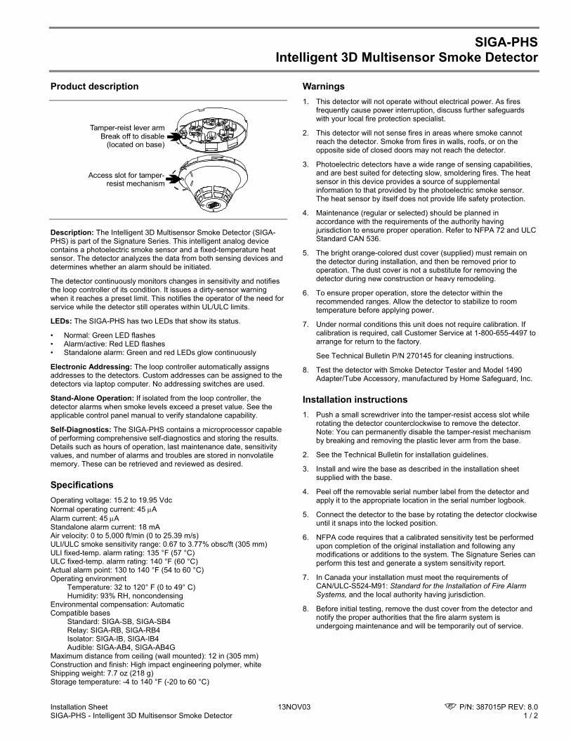
Installation Sheet 13NOV03 P/N: 387015P REV: 8.0 SIGA-PHS - Intelligent 3D Multisensor Smoke Detector 1 / 2
SIGA-PHS Intelligent 3D Multisensor Smoke Detector
Product description
Tamper-reist lever armBreak off to disable
(located on base)
Access slot for tamper-resist mechanism
Description: The Intelligent 3D Multisensor Smoke Detector (SIGA-PHS) is part of the Signature Series. This intelligent analog device contains a photoelectric smoke sensor and a fixed-temperature heat sensor. The detector analyzes the data from both sensing devices and determines whether an alarm should be initiated.
The detector continuously monitors changes in sensitivity and notifies the loop controller of its condition. It issues a dirty-sensor warning when it reaches a preset limit. This notifies the operator of the need for service while the detector still operates within UL/ULC limits.
LEDs: The SIGA-PHS has two LEDs that show its status.
• Normal: Green LED flashes • Alarm/active: Red LED flashes • Standalone alarm: Green and red LEDs glow continuously
Electronic Addressing: The loop controller automatically assigns addresses to the detectors. Custom addresses can be assigned to the detectors via laptop computer. No addressing switches are used.
Stand-Alone Operation: If isolated from the loop controller, the detector alarms when smoke levels exceed a preset value. See the applicable control panel manual to verify standalone capability.
Self-Diagnostics: The SIGA-PHS contains a microprocessor capable of performing comprehensive self-diagnostics and storing the results. Details such as hours of operation, last maintenance date, sensitivity values, and number of alarms and troubles are stored in nonvolatile memory. These can be retrieved and reviewed as desired.
Specifications Operating voltage: 15.2 to 19.95 Vdc Normal operating current: 45 µA Alarm current: 45 µA Standalone alarm current: 18 mA Air velocity: 0 to 5,000 ft/min (0 to 25.39 m/s) ULI/ULC smoke sensitivity range: 0.67 to 3.77% obsc/ft (305 mm) ULI fixed-temp. alarm rating: 135 °F (57 °C) ULC fixed-temp. alarm rating: 140 °F (60 °C) Actual alarm point: 130 to 140 °F (54 to 60 °C) Operating environment
Temperature: 32 to 120° F (0 to 49° C) Humidity: 93% RH, noncondensing
Environmental compensation: Automatic Compatible bases Standard: SIGA-SB, SIGA-SB4 Relay: SIGA-RB, SIGA-RB4 Isolator: SIGA-IB, SIGA-IB4 Audible: SIGA-AB4, SIGA-AB4G Maximum distance from ceiling (wall mounted): 12 in (305 mm) Construction and finish: High impact engineering polymer, white Shipping weight: 7.7 oz (218 g) Storage temperature: -4 to 140 °F (-20 to 60 °C)
Warnings 1. This detector will not operate without electrical power. As fires
frequently cause power interruption, discuss further safeguards with your local fire protection specialist.
2. This detector will not sense fires in areas where smoke cannot reach the detector. Smoke from fires in walls, roofs, or on the opposite side of closed doors may not reach the detector.
3. Photoelectric detectors have a wide range of sensing capabilities, and are best suited for detecting slow, smoldering fires. The heat sensor in this device provides a source of supplemental information to that provided by the photoelectric smoke sensor. The heat sensor by itself does not provide life safety protection.
4. Maintenance (regular or selected) should be planned in accordance with the requirements of the authority having jurisdiction to ensure proper operation. Refer to NFPA 72 and ULC Standard CAN 536.
5. The bright orange-colored dust cover (supplied) must remain on the detector during installation, and then be removed prior to operation. The dust cover is not a substitute for removing the detector during new construction or heavy remodeling.
6. To ensure proper operation, store the detector within the recommended ranges. Allow the detector to stabilize to room temperature before applying power.
7. Under normal conditions this unit does not require calibration. If calibration is required, call Customer Service at 1-800-655-4497 to arrange for return to the factory.
See Technical Bulletin P/N 270145 for cleaning instructions.
8. Test the detector with Smoke Detector Tester and Model 1490 Adapter/Tube Accessory, manufactured by Home Safeguard, Inc.
Installation instructions 1. Push a small screwdriver into the tamper-resist access slot while
rotating the detector counterclockwise to remove the detector. Note: You can permanently disable the tamper-resist mechanism by breaking and removing the plastic lever arm from the base.
2. See the Technical Bulletin for installation guidelines.
3. Install and wire the base as described in the installation sheet supplied with the base.
4. Peel off the removable serial number label from the detector and apply it to the appropriate location in the serial number logbook.
5. Connect the detector to the base by rotating the detector clockwise until it snaps into the locked position.
6. NFPA code requires that a calibrated sensitivity test be performed upon completion of the original installation and following any modifications or additions to the system. The Signature Series can perform this test and generate a system sensitivity report.
7. In Canada your installation must meet the requirements of CAN/ULC-S524-M91: Standard for the Installation of Fire Alarm Systems, and the local authority having jurisdiction.
8. Before initial testing, remove the dust cover from the detector and notify the proper authorities that the fire alarm system is undergoing maintenance and will be temporarily out of service.
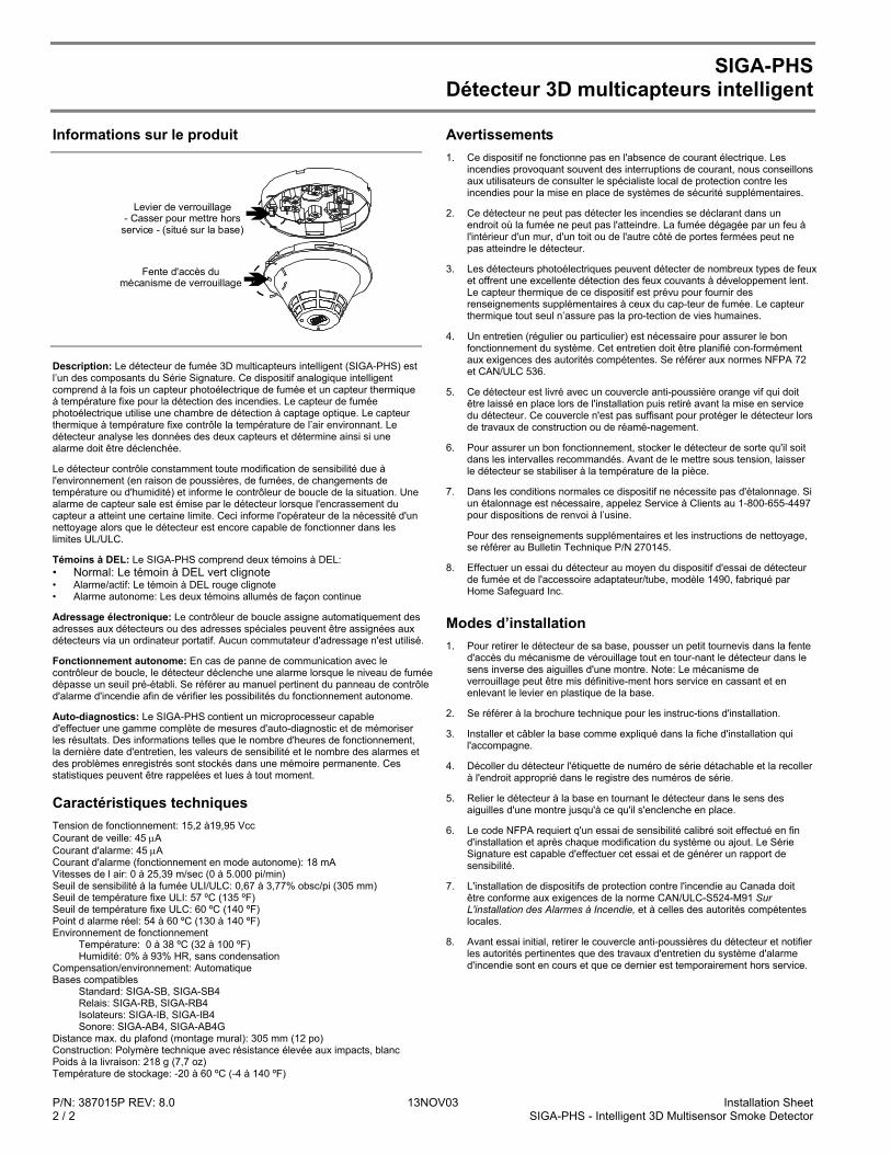
P/N: 387015P REV: 8.0 13NOV03 Installation Sheet 2 / 2 SIGA-PHS - Intelligent 3D Multisensor Smoke Detector
SIGA-PHS Détecteur 3D multicapteurs intelligent
Informations sur le produit
Levier de verrouillage- Casser pour mettre hors
service - (situé sur la base)
Fente d'accès du mécanisme de verrouillage
Description: Le détecteur de fumée 3D multicapteurs intelligent (SIGA-PHS) est l’un des composants du Série Signature. Ce dispositif analogique intelligent comprend à la fois un capteur photoélectrique de fumée et un capteur thermique à température fixe pour la détection des incendies. Le capteur de fumée photoélectrique utilise une chambre de détection à captage optique. Le capteur thermique à température fixe contrôle la température de l’air environnant. Le détecteur analyse les données des deux capteurs et détermine ainsi si une alarme doit être déclenchée.
Le détecteur contrôle constamment toute modification de sensibilité due à l'environnement (en raison de poussières, de fumées, de changements de température ou d'humidité) et informe le contrôleur de boucle de la situation. Une alarme de capteur sale est émise par le détecteur lorsque l'encrassement du capteur a atteint une certaine limite. Ceci informe l'opérateur de la nécessité d'un nettoyage alors que le détecteur est encore capable de fonctionner dans les limites UL/ULC.
Témoins à DEL: Le SIGA-PHS comprend deux témoins à DEL: • Normal: Le témoin à DEL vert clignote • Alarme/actif: Le témoin à DEL rouge clignote • Alarme autonome: Les deux témoins allumés de façon continue
Adressage électronique: Le contrôleur de boucle assigne automatiquement des adresses aux détecteurs ou des adresses spéciales peuvent être assignées aux détecteurs via un ordinateur portatif. Aucun commutateur d'adressage n'est utilisé.
Fonctionnement autonome: En cas de panne de communication avec le contrôleur de boucle, le détecteur déclenche une alarme lorsque le niveau de fumée dépasse un seuil pré-établi. Se référer au manuel pertinent du panneau de contrôle d'alarme d'incendie afin de vérifier les possibilités du fonctionnement autonome.
Auto-diagnostics: Le SIGA-PHS contient un microprocesseur capable d'effectuer une gamme complète de mesures d'auto-diagnostic et de mémoriser les résultats. Des informations telles que le nombre d'heures de fonctionnement, la dernière date d'entretien, les valeurs de sensibilité et le nombre des alarmes et des problèmes enregistrés sont stockés dans une mémoire permanente. Ces statistiques peuvent être rappelées et lues à tout moment.
Caractéristiques techniques Tension de fonctionnement: 15,2 à19,95 Vcc Courant de veille: 45 µA Courant d'alarme: 45 µA Courant d'alarme (fonctionnement en mode autonome): 18 mA Vitesses de l air: 0 à 25,39 m/sec (0 à 5.000 pi/min) Seuil de sensibilité à la fumée ULI/ULC: 0,67 à 3,77% obsc/pi (305 mm) Seuil de température fixe ULI: 57 ºC (135 ºF) Seuil de température fixe ULC: 60 ºC (140 ºF) Point d alarme réel: 54 à 60 ºC (130 à 140 ºF) Environnement de fonctionnement
Température: 0 à 38 ºC (32 à 100 ºF) Humidité: 0% à 93% HR, sans condensation
Compensation/environnement: Automatique Bases compatibles Standard: SIGA-SB, SIGA-SB4 Relais: SIGA-RB, SIGA-RB4 Isolateurs: SIGA-IB, SIGA-IB4 Sonore: SIGA-AB4, SIGA-AB4G Distance max. du plafond (montage mural): 305 mm (12 po) Construction: Polymère technique avec résistance élevée aux impacts, blanc Poids à la livraison: 218 g (7,7 oz) Température de stockage: -20 à 60 ºC (-4 à 140 ºF)
Avertissements 1. Ce dispositif ne fonctionne pas en l'absence de courant électrique. Les
incendies provoquant souvent des interruptions de courant, nous conseillons aux utilisateurs de consulter le spécialiste local de protection contre les incendies pour la mise en place de systèmes de sécurité supplémentaires.
2. Ce détecteur ne peut pas détecter les incendies se déclarant dans un endroit où la fumée ne peut pas l'atteindre. La fumée dégagée par un feu à l'intérieur d'un mur, d'un toit ou de l'autre côté de portes fermées peut ne pas atteindre le détecteur.
3. Les détecteurs photoélectriques peuvent détecter de nombreux types de feux et offrent une excellente détection des feux couvants à développement lent. Le capteur thermique de ce dispositif est prévu pour fournir des renseignements supplémentaires à ceux du cap-teur de fumée. Le capteur thermique tout seul n’assure pas la pro-tection de vies humaines.
4. Un entretien (régulier ou particulier) est nécessaire pour assurer le bon fonctionnement du système. Cet entretien doit être planifié con-formément aux exigences des autorités compétentes. Se référer aux normes NFPA 72 et CAN/ULC 536.
5. Ce détecteur est livré avec un couvercle anti-poussière orange vif qui doit être laissé en place lors de l'installation puis retiré avant la mise en service du détecteur. Ce couvercle n'est pas suffisant pour protéger le détecteur lors de travaux de construction ou de réamé-nagement.
6. Pour assurer un bon fonctionnement, stocker le détecteur de sorte qu'il soit dans les intervalles recommandés. Avant de le mettre sous tension, laisser le détecteur se stabiliser à la température de la pièce.
7. Dans les conditions normales ce dispositif ne nécessite pas d'étalonnage. Si un étalonnage est nécessaire, appelez Service à Clients au 1-800-655-4497 pour dispositions de renvoi à l’usine.
Pour des renseignements supplémentaires et les instructions de nettoyage, se référer au Bulletin Technique P/N 270145.
8. Effectuer un essai du détecteur au moyen du dispositif d'essai de détecteur de fumée et de l'accessoire adaptateur/tube, modèle 1490, fabriqué par Home Safeguard Inc.
Modes d’installation 1. Pour retirer le détecteur de sa base, pousser un petit tournevis dans la fente
d'accès du mécanisme de vérouillage tout en tour-nant le détecteur dans le sens inverse des aiguilles d'une montre. Note: Le mécanisme de verrouillage peut être mis définitive-ment hors service en cassant et en enlevant le levier en plastique de la base.
2. Se référer à la brochure technique pour les instruc-tions d'installation.
3. Installer et câbler la base comme expliqué dans la fiche d'installation qui l'accompagne.
4. Décoller du détecteur l'étiquette de numéro de série détachable et la recoller à l'endroit approprié dans le registre des numéros de série.
5. Relier le détecteur à la base en tournant le détecteur dans le sens des aiguilles d'une montre jusqu'à ce qu'il s'enclenche en place.
6. Le code NFPA requiert q'un essai de sensibilité calibré soit effectué en fin d'installation et après chaque modification du système ou ajout. Le Série Signature est capable d'effectuer cet essai et de générer un rapport de sensibilité.
7. L'installation de dispositifs de protection contre l'incendie au Canada doit être conforme aux exigences de la norme CAN/ULC-S524-M91 Sur L'installation des Alarmes à Incendie, et à celles des autorités compétentes locales.
8. Avant essai initial, retirer le couvercle anti-poussières du détecteur et notifier les autorités pertinentes que des travaux d'entretien du système d'alarme d'incendie sont en cours et que ce dernier est temporairement hors service.

PRODUCT INFORMATION
INSTALLATION SHEET
PRODUCT DIAGRAM
DATE: 28APR99
SHEET P/N: P-047550-1899 FILE: P-047550-1899.CDR
REVISION LEVEL: 1.0
CREATED BY: D. Chinell
APPROVED BY: R. Right
WARNINGS
RELATED DOCUMENTSTechnical Bulletin (P/N 270145)
Description: The Intelligent 3D Multisensor Smoke Detector (PHSI) is part of the Signature Series. This intelligent analog device contains a photoelectric smoke sensor and a fixed-temperature heat sensor. The detector analyzes the data from both sensing devices and determines whether an alarm should be initiated.
The detector continuously monitors changes in sensitivity and notifies the loop controller of its condition. It issues a dirty-sensor warning when it reaches a preset limit. This notifies the operator of the need for service while the detector still operates.
LEDs: The PHSI has two LEDs that show its status.
Normal: Green LED flashesAlarm/active: Red LED flashesStandalone alarm: Green and red LEDs glow continuously
Electronic Addressing: The loop controller automatically assigns addresses to the detectors. Custom addresses can be assigned to the detectors via laptop computer. No addressing switches are used.
Stand-Alone Operation: If isolated from the loop controller, the detector alarms when smoke levels exceed a preset value. See the applicable control panel manual to verify standalone capability.
Self-Diagnostics: The PHSI contains a microprocessor capable of performing comprehensive self-diagnostics and storing the results. Details such as hours of operation, last maintenance date, sensitivity values, and number of alarms and troubles are stored in non-volatile memory. These can be retrieved and reviewed as desired.
1) Push a small screwdriver into the tamper-resist access slot while rotating the detector counterclockwise to remove the detector. Note: You can permanently disable the tamper-resist mechanism by breaking and removing the plastic lever arm from the base.
2) See the Technical Bulletin for installation guidelines.
3) Install and wire the base as described in the installation sheet supplied with the base.
4) Peel off the removable serial number label from the detector and apply it to the appropriate location in the serial number log book.
5) Connect the detector to the base by rotating the detector clockwise until it snaps into the locked position.
6) Before initial testing, remove the dust cover from the detector and notify the proper authorities that the fire alarm system is undergoing maintenance and will be temporarily out of service.
INSTALLATION INSTRUCTIONS
1) This detector will NOT operate without electrical power. As fires frequently cause power interruption, discuss further safeguards with your local fire protection specialist.
2) This detector will NOT sense fires in areas where smoke cannot reach the detector. Smoke from fires in walls, roofs, or on the opposite side of closed doors may not reach the detector.
3) Photoelectric detectors have a wide range of sensing capabilities, and are best suited for detecting slow, smoldering fires. The heat sensor in this device provides a source of supplemental information to that provided by the photoelectric smoke sensor. The heat sensor by itself does NOT provide life safety protection.
4) Maintenance (regular or selected) should be planned in accordance with the requirements of the Authority Having Jurisdiction to ensure proper operation.
5) The bright orange-colored dust cover (supplied) MUST remain on the detector during installation, and then be removed prior to operation. The dust cover is NOT a substitute for removing the detector during new construction or heavy remodeling.
6) To ensure proper operation, store the detector within the recommended ranges. Allow the detector to stabilize to room
temperature before applying power.
7) Under normal conditions, this unit does not require calibration. However, if calibration is required, return to:
GS Building Systems CorporationNorth Main StreetPittsfield, ME 04967-1500
See the Technical Bulletin for cleaning instructions.
8) Test the detector with Smoke Detector Tester and Model 1490 Adapter/Tube Accessory, manufactured by Home Safeguard, Inc.
SPECIFICATIONS
Operating voltage range: 15.2 - 19.95 VdcNormal operating current: 45 µAAlarm current: 45 µAStandalone alarm current: 18 mAActual alarm point: 130 to 140 °F (54 to 60 °C)Air velocity range: 0 to 5000 ft/min (0 to 25.39 m/s)Operating temperature range: 32 to 100 °F (0 to 38 °C)Operating humidity range: 0 to 93 % RH, non-condensingStorage temperature range: -4 to 140 °F (-20 to 60 °C)Environmental compensation: AutomaticConstruction and finish: High impact engineering polymer, whiteCompatible bases
Standard: SB, SB4Relay: RB, RB4Isolator: IB, IB4, IBSAudible: AB4
Shipping weight: 7.7 oz (218 g)Maximum distance from ceiling (wall mounted): 12 in (305 mm)
Tamper-Resist Lever Arm- Break off to disable -
(Located on Base)
Access Slot forTamper-Resist Mechanism
SIGA-PHSIIntelligent 3D Multisensor
Smoke Detector
EDWARDS SYSTEMS TECHNOLOGY
6411 Parkland DriveSarasota, FL 34243USA
625 6th Street EastOwen Sound, OntarioCanada N4K 5P8
TM

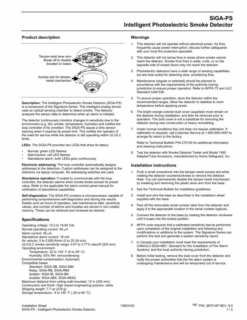
Installation Sheet 13NOV03 P/N: 387014P REV: 8.0 SIGA-PS - Intelligent Photoelectric Smoke Detector 1 / 2
SIGA-PS Intelligent Photoelectric Smoke Detector
Product description
Tamper-reist lever armBreak off to disable
(located on base)
Access slot for tamper-resist mechanism
Description: The Intelligent Photoelectric Smoke Detector (SIGA-PS) is a component of the Signature Series. This intelligent analog device uses an optical sensing chamber to detect smoke. The detector analyzes the sensor data to determine when an alarm is initiated.
The detector continuously monitors changes in sensitivity due to the environment (e.g. dirt, smoke, temperature, humidity) and notifies the loop controller of its condition. The SIGA-PS issues a dirty sensor warning when it reaches its preset limit. This notifies the operator of the need for service while the detector is still operating within UL/ULC limits.
LEDs: The SIGA-PS provides two LEDs that show its status:
• Normal: green LED flashes • Alarm/active: red LED flashes • Standalone alarm: both LEDs glow continuously
Electronic addressing: The loop controller automatically assigns addresses to the detectors. Custom addresses can be assigned to the detectors via laptop computer. No addressing switches are used.
Standalone operation: If unable to communicate with the loop controller, the detector alarms when smoke levels exceed its preset value. Refer to the applicable fire alarm control panel manual for verification of standalone capabilities.
Self-diagnostics: The SIGA-PS contains a microprocessor capable of performing comprehensive self-diagnostics and storing the results. Details such as hours of operation, last maintenance date, sensitivity values, and number of alarms and troubles are stored in non-volatile memory. These can be retrieved and reviewed as desired.
Specifications Operating voltage: 15.2 to 19.95 Vdc Normal operating current: 45 µA Alarm current: 45 µA Standalone alarm current: 18 mA Air velocity: 0 to 5,000 ft/min (0 to 25.39 m/s) ULI/ULC smoke sensitivity range: 0.67 to 3.77% obsc/ft (305 mm) Operating environment
Temperature: 32 to 120° F (0 to 49° C) Humidity: 93% RH, noncondensing
Environmental compensation: Automatic Compatible bases Standard: SIGA-SB, SIGA-SB4 Relay: SIGA-RB, SIGA-RB4 Isolator: SIGA-IB, SIGA-IB4 Audible: SIGA-AB4, SIGA-AB4G Maximum distance from ceiling wall-mounted: 12 in (305 mm) Construction and finish: High impact engineering polymer, white Shipping weight: 7.7 oz (218 g) Storage temperature: -4 to 140 °F (-20 to 60 °C)
Warnings 1. This detector will not operate without electrical power. As fires
frequently cause power interruption, discuss further safeguards with your local fire protection specialist.
2. This detector will not sense fires in areas where smoke cannot reach the detector. Smoke from fires in walls, roofs, or on the opposite side of closed doors may not reach the detector.
3. Photoelectric detectors have a wide range of sensing capabilities, but are best suited for detecting slow, smoldering fires.
4. Maintenance (regular or selected) should be planned in accordance with the requirements of the authority having jurisdiction to ensure proper operation. Refer to NFPA 72 and ULC Standard CAN 536.
5. To ensure proper operation, store the detector within the recommended ranges. Allow the detector to stabilize to room temperature before applying power.
6. The bright orange-colored dust cover (supplied) must remain on the detector during installation, and then be removed prior to operation. The dust cover is not a substitute for removing the detector during new construction or heavy remodeling.
7. Under normal conditions this unit does not require calibration. If calibration is required, call Customer Service at 1-800-655-4497 to arrange for return to the factory.
Refer to Technical Bulletin P/N 270145 for additional information and cleaning instructions.
8. Test the detector with Smoke Detector Tester and Model 1490 Adapter/Tube Accessory, manufactured by Home Safeguard, Inc.
Installation instructions 1. Push a small screwdriver into the tamper-resist access slot while
rotating the detector counterclockwise to remove the detector. Note: You can permanently disable the tamper-resist mechanism by breaking and removing the plastic lever arm from the base.
2. See the Technical Bulletin for installation guidelines.
3. Install and wire the base as described in the installation sheet supplied with the base.
4. Peel off the removable serial number label from the detector and apply it to the appropriate location in the serial number logbook.
5. Connect the detector to the base by rotating the detector clockwise until it snaps into the locked position.
6. NFPA code requires that a calibrated sensitivity test be performed upon completion of the original installation and following any modifications or additions to the system. The Signature Series can perform this test and generate a system sensitivity report.
7. In Canada your installation must meet the requirements of CAN/ULC-S524-M91: Standard for the Installation of Fire Alarm Systems, and the local authority having jurisdiction.
8. Before initial testing, remove the dust cover from the detector and notify the proper authorities that the fire alarm system is undergoing maintenance and will be temporarily out of service.
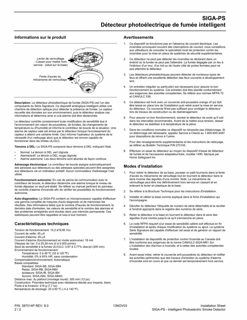
P/N: 387014P REV: 8.0 13NOV03 Installation Sheet 2 / 2 SIGA-PS - Intelligent Photoelectric Smoke Detector
SIGA-PS Détecteur photoélectrique de fumée intelligent
Informations sur le produit
Levier de verrouillage- Casser pour mettre hors
service - (situé sur la base)
Fente d'accès du mécanisme de verrouillage
Description: Le détecteur photoélectrique de fumée (SIGA-PS) est l’un des composants du Série Signature. Ce dispositif analogique intelligent utilise une chambre de détection optique pour détecter la présence de fumée. Le capteur recueille des données sur son environnement, puis le détecteur analyse ces informations et détermine ainsi si une alarme doit être déclenchée.
Le détecteur contrôle constamment toute modification de sensibilité due à l'environnement (en raison de poussières, de fumées, de changements de température ou d'humidité) et informe le contrôleur de boucle de la situation. Une alarme de capteur sale est émise par le détecteur lorsque l'encrassement du capteur a atteint une certaine limite. Ceci informe l'opérateur du système de la nécessité d'un nettoyage alors que le détecteur est encore capable de fonctionner dans les limites UL/ULC.
Témoins à DEL: Le SIGA-PS comprend deux témoins à DEL indiquant l'état.
• Normal: Le témoin à DEL vert clignote • Alarme/actif: Le témoin à DEL rouge clignote • Alarme autonome: Les deux témoins sont allumés de façon continue
Adressage électronique: Le contrôleur de boucle assigne automatiquement des adresses aux détecteurs ou des adresses spéciales peuvent être assignées aux détecteurs via un ordinateur portatif. Aucun commutateur d'adressage n'est utilisé.
Fonctionnement autonome: En cas de panne de communication avec le contrôleur de boucle, le détecteur déclenche une alarme lorsque le niveau de fumée dépasse un seuil pré-établi. Se référer au manuel pertinent du panneau de contrôle d'alarme d'incendie afin de vérifier les possibilités du fonctionnement autonome.
Auto-diagnostics: Le SIGA-PS contient un microprocesseur capable d'effectuer une gamme complète de mesures d'auto-diagnostic et de mémoriser les résultats. Des informations telles que le nombre d'heures de fonctionnement, la dernière date d'entretien, les valeurs de sensibilité et le nombre des alarmes et des problèmes enregistrés sont stockés dans une mémoire permanente. Ces statistiques peuvent être rappelées et lues à tout moment.
Caractéristiques techniques Tension de fonctionnement: 15,2 à19,95 Vcc Courant de veille: 45 µA Courant d'alarme: 45 µA Courant d'alarme (fonctionnement en mode autonome): 18 mA Vitesses de l’air: 0 à 25,39 m/s (0 à 5.000 pi/min) Seuil de sensibilité à la fumée ULI/ULC: 0,67 à 3,77% obsc/pi (305 mm) Environnement de fonctionnement
Température: 0 à 49 ºC (32 à 120 ºF) Humidité: 0% à 93% HR, sans condensation
Compensation/environnement: Automatique Bases compatibles Standard: SIGA-SB, SIGA-SB4 Relais: SIGA-RB, SIGA-RB4 Isolateurs: SIGA-IB, SIGA-IB4 Sonore: SIGA-AB4, SIGA-AB4G Distance max. du plafond (montage mural): 305 mm (12 po) Construction: Polymère technique avec résistance élevée aux impacts, blanc Poids à la livraison: 218 g (7,7 oz) ttempérature de stockage: 20 à 60 ºC (-4 à 140 ºF)
Avertissements 1. Ce dispositif ne fonctionne pas en l'absence de courant électrique. Les
incendies provoquant souvent des interruptions de courant, nous conseillons aux utilisateurs de consulter le spécialiste local de protection contre les incendies pour la mise en place de systèmes de sécurité supplémentaires.
2. Ce détecteur ne peut pas détecter les incendies se déclarant dans un endroit où la fumée ne peut pas l'atteindre. La fumée dégagée par un feu à l'intérieur d'un mur, d'un toit ou de l'autre côté de portes fermées peut ne pas atteindre le détecteur.
3. Les détecteurs photoélectriques peuvent détecter de nombreux types de feux et offrent une excellente détection des feux couvants à développement lent.
4. Un entretien (régulier ou particulier) est nécessaire pour assurer le bon fonctionnement du système. Cet entretien doit être planifié conformément aux exigences des autorités compétentes. Se référer aux normes NFPA 72 et CAN/ULC 536.
5. Ce détecteur est livré avec un couvercle anti-poussière orange vif qui doit être laissé en place lors de l'installation puis retiré avant la mise en service du détecteur. Ce couvercle N'est pas suffisant pour protéger le détecteur lors de travaux de construction ou de réaménagement.
6. Pour assurer un bon fonctionnement, stocker le détecteur de sorte qu'il soit dans les intervalles recommandés. Avant de le mettre sous tension, laisser le détecteur se stabiliser à la température de la pièce.
7. Dans les conditions normales ce dispositif ne nécessite pas d'étalonnage. Si un étalonnage est nécessaire, appelez Service à Clients au 1-800-655-4497 pour dispositions de renvoi à l’usine.
Pour des renseignements supplémentaires et les instructions de nettoyage, se référer au Bulletin Technique P/N 270145.
8. Effectuer un essai du détecteur au moyen du dispositif d'essai de détecteur de fumée et de l'accessoire adaptateur/tube, modèle 1490, fabriqué par Home Safeguard Inc.
Modes d’installation 1. Pour retirer le détecteur de sa base, pousser un petit tournevis dans la fente
d'accès du mécanisme de vérouillage tout en tournant le détecteur dans le sens inverse des aiguilles d'une montre. Note: Le mécanisme de verrouillage peut être mis définitivement hors service en cassant et en enlevant le levier en plastique de la base.
2. Se référer à la Brochure Technique pour les instructions d'installation.
3. Installer et câbler la base comme expliqué dans la fiche d'installation qui l'accompagne.
4. Décoller du détecteur l'étiquette de numéro de série détachable et la recoller à l'endroit approprié dans le registre des numéros de série.
5. Relier le détecteur à la base en tournant le détecteur dans le sens des aiguilles d'une montre jusqu'à ce qu'il s'enclenche en place.
6. Le code NFPA requiert q'un essai de sensibilité calibré soit effectué en fin d'installation et après chaque modification du système ou ajout. Le système Série Signature est capable d'effectuer cet essai et de générer un rapport de sensibilité.
7. L'installation de dispositifs de protection contre l'incendie au Canada doit être conforme aux exigences de la norme CAN/ULC-S524-M91 Sur L'installation des Alarmes à Incendie, et à celles des autorités compétentes locales.
8. Avant essai initial, retirer le couvercle anti-poussières du détecteur et notifier les autorités pertinentes que des travaux d'entretien du système d'alarme d'incendie sont en cours et que ce dernier est temporairement hors service.
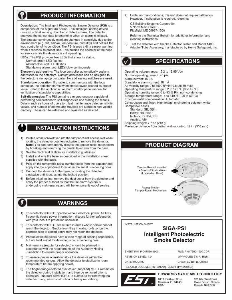
PRODUCT DIAGRAM
PRODUCT INFORMATION
Description: The Intelligent Photoelectric Smoke Detector (PSI) is a component of the Signature Series. This intelligent analog device uses an optical sensing chamber to detect smoke. The detector analyzes the sensor data to determine when an alarm is initiated.
The detector continuously monitors changes in sensitivity due to the environment (e.g. dirt, smoke, temperature, humidity) and notifies the loop controller of its condition. The PSI issues a dirty sensor warning when it reaches its preset limit. This notifies the operator of the need for service while the detector is still operating.
LEDs: The PSI provides two LEDs that show its status.Normal: green LED flashesAlarm/active: red LED flashesStandalone alarm: both LEDs glow continuously
Electronic addressing: The loop controller automatically assigns addresses to the detectors. Custom addresses can be assigned to the detectors via laptop computer. No addressing switches are used.
Standalone operation: If unable to communicate with the loop controller, the detector alarms when smoke levels exceed its preset value. Refer to the applicable fire alarm control panel manual for verification of standalone capabilities.
Self-diagnostics: The PSI contains a microprocessor capable of performing comprehensive self-diagnostics and storing the results. Details such as hours of operation, last maintenance date, sensitivity values, and number of alarms and troubles are stored in non-volatile memory. These can be retrieved and reviewed as desired.
INSTALLATION INSTRUCTIONS
1) Push a small screwdriver into the tamper-resist access slot while rotating the detector counterclockwise to remove the detector. Note: You can permanently disable the tamper-resist mechanism by breaking and removing the plastic lever arm from the base.
2) See the Technical Bulletin for installation guidelines.
3) Install and wire the base as described in the installation sheet supplied with the base.
4) Peel off the removable serial number label from the detector and apply it to the appropriate location in the serial number log book.
5) Connect the detector to the base by rotating the detector clockwise until it snaps into the locked position.
6) Before initial testing, remove the dust cover from the detector and notify the proper authorities that the fire alarm system is undergoing maintenance and will be temporarily out of service.
1) This detector will NOT operate without electrical power. As fires frequently cause power interruption, discuss further safeguards with your local fire protection specialist.
2) This detector will NOT sense fires in areas where smoke cannot reach the detector. Smoke from fires in walls, roofs, or on the opposite side of closed doors may not reach the detector.
3) Photoelectric detectors have a wide range of sensing capabilities, but are best suited for detecting slow, smoldering fires.
4) Maintenance (regular or selected) should be planned in accordance with the requirements of the Authority Having Jurisdiction to ensure proper operation.
5) To ensure proper operation, store the detector within the recommended ranges. Allow the detector to stabilize to room temperature before applying power.
6) The bright orange-colored dust cover (supplied) MUST remain on the detector during installation, and then be removed prior to operation. The dust cover is NOT a substitute for removing the detector during new construction or heavy remodeling.
7) Under normal conditions, this unit does not require calibration. However, if calibration is required, return to:
GS Building Systems Corporation5 North Main StreetPittsfield, ME 04967-1500
Refer to the Technical Bulletin for additional information and cleaning instructions.
8) Test the detector with Smoke Detector Tester and Model 1490 Adapter/Tube Accessory, manufactured by Home Safeguard, Inc.
WARNINGS
Tamper-Resist Lever Arm- Break off to disable -
(Located on Base)
Access Slot forTamper-Resist Mechanism
Operating voltage range: 15.2 to 19.95 VdcNormal operating current: 45 µAAlarm current: 45 µAStandalone alarm current: 18 mAAir velocity range: 0 to 5000 ft/min (0 to 25.39 m/s)Operating temperature range: 32 to 120 °F (0 to 49 °C)Operating humidity range: 0 to 93 % RH, non-condensingStorage temperature range: -4 to 140 °F (-20 to 60 °C)Environmental compensation: AutomaticConstruction and finish: High impact engineering polymer, whiteCompatible bases
Standard: SB, SB4Relay: RB, RB4Isolator: IB, IB4, IBSAudible: AB4
Shipping weight: 7.7 oz (218 g)Maximum distance from ceiling wall-mounted: 12 in. (305 mm)
SPECIFICATIONS
DATE: 04JUN99
INSTALLATION SHEET
SHEET P/N: P-047550-1900
REVISION LEVEL: 1.0
RELATED DOCUMENTS: Technical Bulletin (P/N 270145)
SIGA-PSIIntelligent Photoelectric
Smoke Detector
FILE: P-047550-1900.CDR
CREATED BY: D. Chinell
APPROVED BY: R. Right
EDWARDS SYSTEMS TECHNOLOGY
6411 Parkland DriveSarasota, FL 34243USA
625 6th Street EastOwen Sound, OntarioCanada N4K 5P8
TM

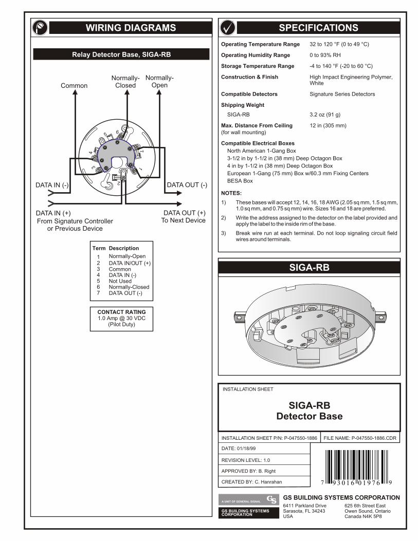
SPECIFICATIONS
SIGA-RB
WIRING DIAGRAMS
Operating Temperature Range 32 to 120 °F (0 to 49 °C)
Operating Humidity Range 0 to 93% RH
Storage Temperature Range -4 to 140 °F (-20 to 60 °C)
Construction & Finish High Impact Engineering Polymer, White
Compatible Detectors Signature Series Detectors
Shipping Weight
SIGA-RB 3.2 oz (91 g)
Max. Distance From Ceiling 12 in (305 mm)(for wall mounting)
Compatible Electrical Boxes
North American 1-Gang Box
3-1/2 in by 1-1/2 in (38 mm) Deep Octagon Box
4 in by 1-1/2 in (38 mm) Deep Octagon Box
European 1-Gang (75 mm) Box w/60.3 mm Fixing Centers
BESA Box
NOTES:
1) These bases will accept 12, 14, 16, 18 AWG (2.05 sq mm, 1.5 sq mm, 1.0 sq mm, and 0.75 sq mm) wire. Sizes 16 and 18 are preferred.
2) Write the address assigned to the detector on the label provided and apply the label to the inside rim of the base.
3) Break wire run at each terminal. Do not loop signaling circuit field wires around terminals.
Term
1
Normally-Closed
45
DATA IN (-)Not Used
7 DATA OUT (-)
CONTACT RATING1.0 Amp @ 30 VDC
(Pilot Duty)
2 DATA IN/OUT (+)3 Common
6
Normally-Open
Description
DATA OUT (-)
DATA OUT (+)To Next DeviceFrom Signature Controller
or Previous Device
DATA IN (-)
DATA IN (+)
56
34
17
2
CommonNormally-
OpenNormally-
Closed
Relay Detector Base, SIGA-RB
INSTALLATION SHEET
INSTALLATION SHEET P/N: P-047550-1886
REVISION LEVEL: 1.0
FILE NAME: P-047550-1886.CDR
SIGA-RBDetector Base
DATE: 01/18/99
CREATED BY: C. Hanrahan
APPROVED BY: B. Right
GS BUILDING SYSTEMSCORPORATION
A UNIT OF GENERAL SIGNALGS BUILDING SYSTEMS CORPORATION6411 Parkland DriveSarasota, FL 34243USA
625 6th Street EastOwen Sound, OntarioCanada N4K 5P8
7 99 3 0 1 6 0 1 9 7 6
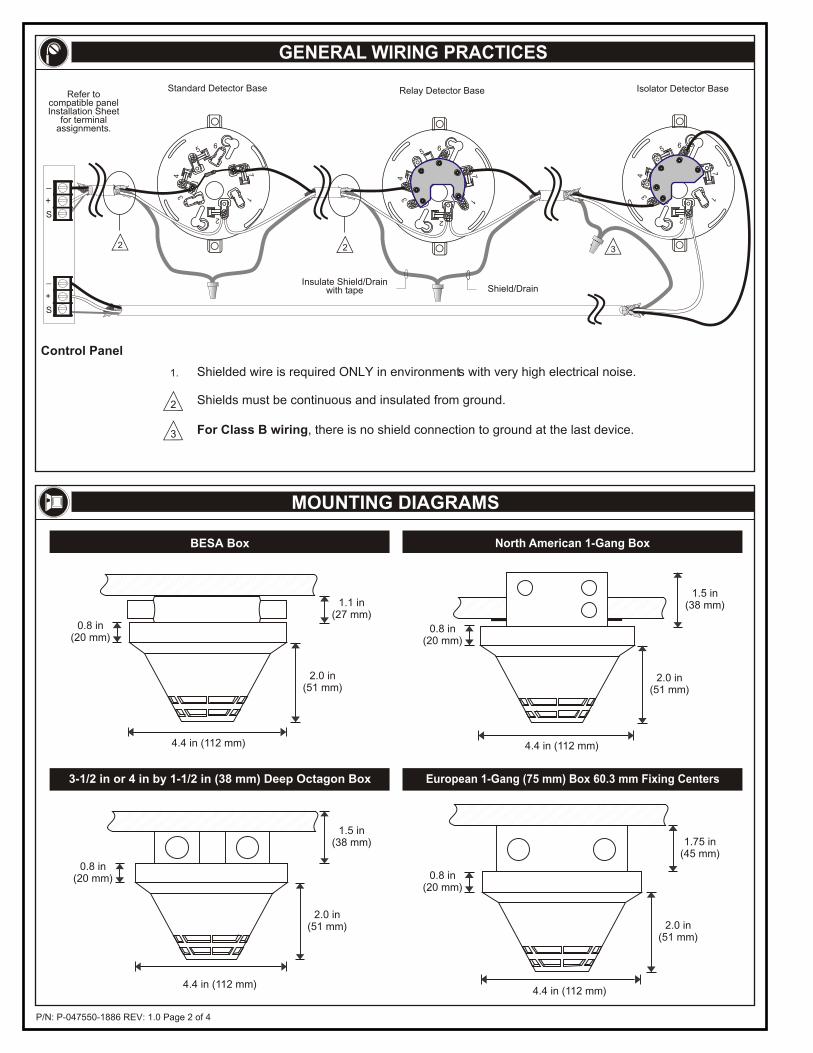
P/N: P-047550-1886 REV: 1.0 Page 2 of 4
GENERAL WIRING PRACTICES
MOUNTING DIAGRAMS
1.1 in(27 mm)
2.0 in(51 mm)
4.4 in (112 mm)
0.8 in(20 mm)
4.4 in (112 mm)
1.5 in(38 mm)
2.0 in(51 mm)
0.8 in(20 mm)
BESA Box North American 1-Gang Box
4.4 in (112 mm)
1.5 in(38 mm)
2.0 in(51 mm)
0.8 in(20 mm)
4.4 in (112 mm)
1.75 in(45 mm)
2.0 in(51 mm)
0.8 in(20 mm)
3-1/2 in or 4 in by 1-1/2 in (38 mm) Deep Octagon Box European 1-Gang (75 mm) Box 60.3 mm Fixing Centers
For Class B wiring, there is no shield connection to ground at the last device.
Control Panel
3
1.
2
Standard Detector Base
2
Relay Detector Base
Insulate Shield/Drainwith tape Shield/Drain
2
56
34
17
2
Isolator Detector Base
3
56
34
17
2
56
34
17
2
Shields must be continuous and insulated from ground.
Shielded wire is required ONLY in environments with very high electrical noise.
+
_
S
+
_
S
Refer tocompatible panelInstallation Sheet
for terminalassignments.
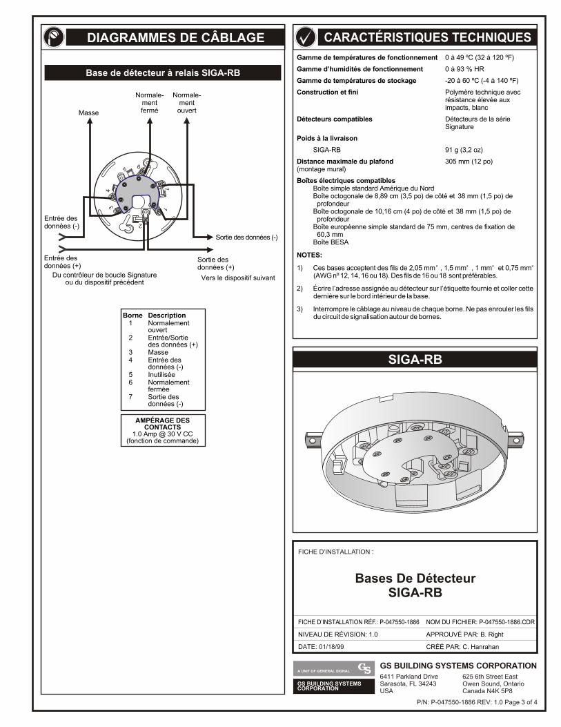
GS BUILDING SYSTEMSCORPORATION
A UNIT OF GENERAL SIGNALGS BUILDING SYSTEMS CORPORATION6411 Parkland DriveSarasota, FL 34243USA
625 6th Street EastOwen Sound, OntarioCanada N4K 5P8
DATE: 01/18/99
FICHE D’INSTALLATION :
FICHE D’INSTALLATION RÉF.: P-047550-1886
NIVEAU DE RÉVISION: 1.0
NOM DU FICHIER: P-047550-1886.CDR
CRÉÉ PAR: C. Hanrahan
APPROUVÉ PAR: B. Right
Bases De DétecteurSIGA-RB
SIGA-RB
Gamme de températures de fonctionnement 0 à 49 ºC (32 à 120 ºF)
Gamme d’humidités de fonctionnement 0 à 93 % HR
Gamme de températures de stockage -20 à 60 ºC (-4 à 140 ºF)
Construction et fini Polymère technique avecrésistance élevée aux impacts, blanc
Détecteurs compatibles Détecteurs de la série Signature
Poids à la livraison
SIGA-RB 91 g (3,2 oz)
Distance maximale du plafond 305 mm (12 po)(montage mural)
Boîtes électriques compatiblesBoîte simple standard Amérique du NordBoîte octogonale de 8,89 cm (3,5 po) de côté et 38 mm (1,5 po) de profondeurBoîte octogonale de 10,16 cm (4 po) de côté et 38 mm (1,5 po) de profondeurBoîte européenne simple standard de 75 mm, centres de fixation de 60,3 mmBoîte BESA
NOTES:
2 2 2 21) Ces bases acceptent des fils de 2,05 mm , 1,5 mm , 1 mm et 0,75 mm(AWG nº 12, 14, 16 ou 18). Des fils de 16 ou 18 sont préférables.
2) Écrire l’adresse assignée au détecteur sur l’étiquette fournie et coller cette dernière sur le bord intérieur de la base.
3) Interrompre le câblage au niveau de chaque borne. Ne pas enrouler les fils du circuit de signalisation autour de bornes.
DIAGRAMMES DE CÂBLAGE CARACTÉRISTIQUES TECHNIQUES
P/N: P-047550-1886 REV: 1.0 Page 3 of 4
56
34
17
2
Entrée des données (+)
Du contrôleur de boucle Signatureou du dispositif précédent
Entrée des données (-)
Vers le dispositif suivant
Sortie des données (-)
Sortie des données (+)
Masse
Normale-mentfermé
Normale-ment
ouvert
AMPÉRAGE DESCONTACTS
1.0 Amp @ 30 V CC(fonction de commande)
Borne Description1 Normalement
ouvert2 Entrée/Sortie
des données (+)3 Masse4 Entrée des
données (-)5 Inutilisée6 Normalement
fermée7 Sortie des
données (-)
Base de détecteur à relais SIGA-RB
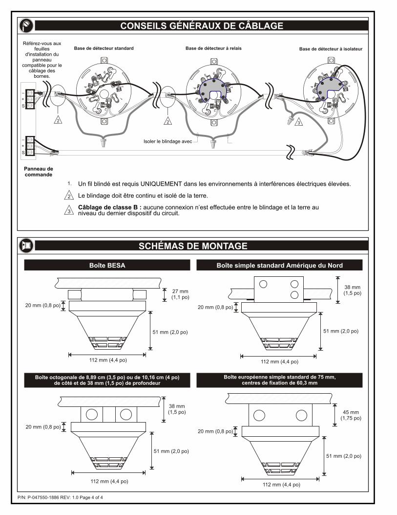
P/N: P-047550-1886 REV: 1.0 Page 4 of 4
27 mm(1,1 po)
51 mm (2,0 po)
112 mm (4,4 po)
20 mm (0,8 po)
112 mm (4,4 po)
38 mm(1,5 po)
51 mm (2,0 po)
20 mm (0,8 po)
112 mm (4,4 po)
38 mm(1,5 po)
51 mm (2,0 po)
20 mm (0,8 po)
112 mm (4,4 po)
45 mm (1,75 po)
51 mm (2,0 po)
20 mm (0,8 po)
Boîte BESA
Boîte octogonale de 8,89 cm (3,5 po) ou de 10,16 cm (4 po)de côté et de 38 mm (1,5 po) de profondeur
Boîte européenne simple standard de 75 mm,centres de fixation de 60,3 mm
CONSEILS GÉNÉRAUX DE CÂBLAGE
SCHÉMAS DE MONTAGE
Boîte simple standard Amérique du Nord
Un fil blindé est requis UNIQUEMENT dans les environnements à interférences électriques élevées.
Le blindage doit être continu et isolé de la terre.
Câblage de classe B : aucune connexion n’est effectuée entre le blindage et la terre au niveau du dernier dispositif du circuit.
Panneau de commande
Isoler le blindage avec
3
1.
2
2 2
56
34
17
2
3
56
34
17
2
56
34
17
2
Base de détecteur standard Base de détecteur à relais Base de détecteur à isolateur
+
_
S
+
_
S
Référez-vous aux feuilles
d'installation du panneau
compatible pour le câblage des
bornes.
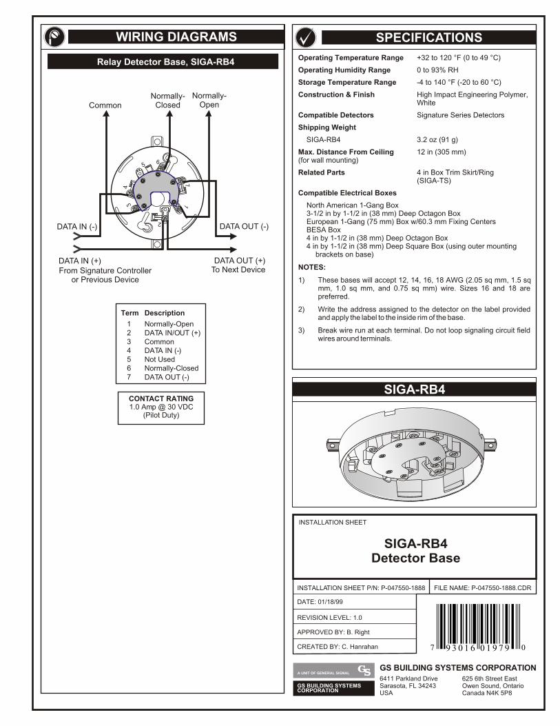
Operating Temperature Range +32 to 120 °F (0 to 49 °C)
Operating Humidity Range 0 to 93% RH
Storage Temperature Range -4 to 140 °F (-20 to 60 °C)
Construction & Finish High Impact Engineering Polymer, White
Compatible Detectors Signature Series Detectors
Shipping Weight
SIGA-RB4 3.2 oz (91 g)
Max. Distance From Ceiling 12 in (305 mm)(for wall mounting)
Related Parts 4 in Box Trim Skirt/Ring(SIGA-TS)
Compatible Electrical Boxes
North American 1-Gang Box3-1/2 in by 1-1/2 in (38 mm) Deep Octagon BoxEuropean 1-Gang (75 mm) Box w/60.3 mm Fixing CentersBESA Box4 in by 1-1/2 in (38 mm) Deep Octagon Box4 in by 1-1/2 in (38 mm) Deep Square Box (using outer mounting
brackets on base)
NOTES:
1) These bases will accept 12, 14, 16, 18 AWG (2.05 sq mm, 1.5 sq mm, 1.0 sq mm, and 0.75 sq mm) wire. Sizes 16 and 18 are preferred.
2) Write the address assigned to the detector on the label provided and apply the label to the inside rim of the base.
3) Break wire run at each terminal. Do not loop signaling circuit field wires around terminals.
SIGA-RB4
Relay Detector Base, SIGA-RB4
SPECIFICATIONSWIRING DIAGRAMS
CONTACT RATING1.0 Amp @ 30 VDC
(Pilot Duty)
From Signature Controlleror Previous Device
DATA OUT (-)
DATA OUT (+)To Next Device
DATA IN (-)
DATA IN (+)
56
34
17
2
CommonNormally-
OpenNormally-
Closed
Normally-Closed
DATA IN (-)Not Used
DATA OUT (-)
DATA IN/OUT (+)Common
Normally-Open
DescriptionTerm
1
45
7
23
6
INSTALLATION SHEET
INSTALLATION SHEET P/N: P-047550-1888
REVISION LEVEL: 1.0
FILE NAME: P-047550-1888.CDR
SIGA-RB4Detector Base
DATE: 01/18/99
CREATED BY: C. Hanrahan
APPROVED BY: B. Right
GS BUILDING SYSTEMSCORPORATION
A UNIT OF GENERAL SIGNALGS BUILDING SYSTEMS CORPORATION6411 Parkland DriveSarasota, FL 34243USA
625 6th Street EastOwen Sound, OntarioCanada N4K 5P8
7 09 3 0 1 6 0 1 9 7 9
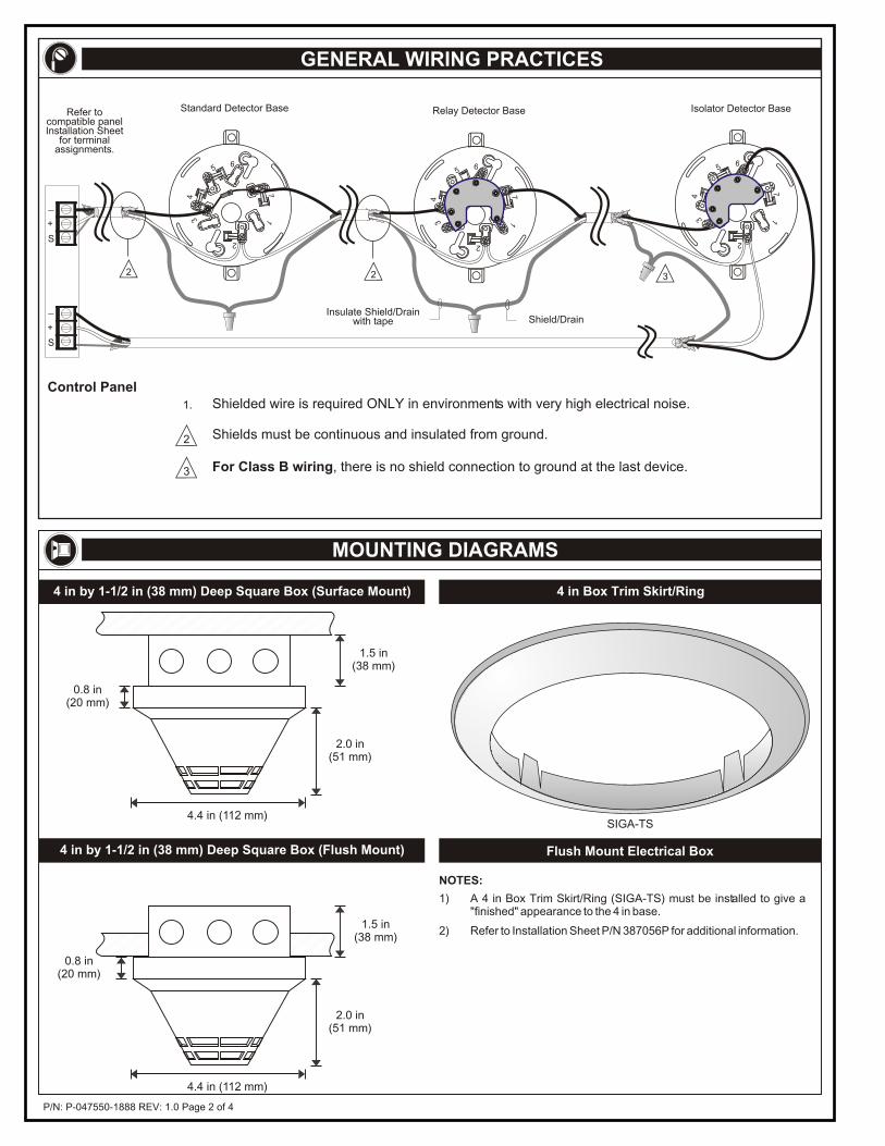
P/N: P-047550-1888 REV: 1.0 Page 2 of 4
GENERAL WIRING PRACTICES
MOUNTING DIAGRAMS
4.4 in (112 mm)
1.5 in(38 mm)
2.0 in(51 mm)
0.8 in(20 mm)
1.5 in(38 mm)
4.4 in (112 mm)
2.0 in(51 mm)
0.8 in(20 mm)
4 in by 1-1/2 in (38 mm) Deep Square Box (Flush Mount)
4 in by 1-1/2 in (38 mm) Deep Square Box (Surface Mount) 4 in Box Trim Skirt/Ring
Flush Mount Electrical Box
1) A 4 in Box Trim Skirt/Ring (SIGA-TS) must be installed to give a "finished" appearance to the 4 in base.
2) Refer to Installation Sheet P/N 387056P for additional information.
NOTES:
SIGA-TS
For Class B wiring, there is no shield connection to ground at the last device.
Control Panel
3
1.
2
Refer tocompatible panelInstallation Sheet
for terminalassignments.
Standard Detector Base
2
Relay Detector Base
Insulate Shield/Drainwith tape Shield/Drain
2
56
34
17
2
Isolator Detector Base
3
56
34
17
2
56
34
17
2
Shields must be continuous and insulated from ground.
Shielded wire is required ONLY in environments with very high electrical noise.
+
_
S
+
_
S
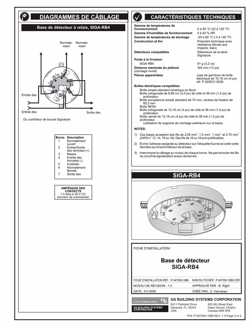
GS BUILDING SYSTEMSCORPORATION
A UNIT OF GENERAL SIGNALGS BUILDING SYSTEMS CORPORATION6411 Parkland DriveSarasota, FL 34243USA
625 6th Street EastOwen Sound, OntarioCanada N4K 5P8
Gamme de températures de fonctionnement 0 à 49 C (32 à 120 F)
Gamme d’humidités de fonctionnement 0 à 93 % HR
Gamme de températures de stockage -20 à 60 C (-4 à 140 F)
Construction et fini Polymère technique avec résistance élevée aux impacts, blanc
Détecteurs compatibles Détecteurs de la sérieSignature
Poids à la livraison
SIGA-RB4 91 g (3,2 oz)
Distance maximale du plafond 305 mm (12 po)(montage mural)
Pièces apparentées Jupe de garniture de boîteélectrique de 10,16 cm (4 po) réf. P-025031-0039
Boîtes électriques compatibles
Boîte simple standard Amérique du NordBoîte octogonale de 8,89 cm (3,5 po) de côté et 38 mm (1,5 po) de profondeurBoîte européenne simple standard de 75 mm, centres de fixation de 60,3 mmBoîte BESABoîte octogonale de 10,16 cm (4 po) de côté et 38 mm (1,5 po) de profondeurBoîte carrée de 10,16 cm (4 po) de côté et 38 mm (1,5 po) de profondeur (utilisation de supports de montage extérieurs sur la base)
NOTES:
2 2 2 2 1) Ces bases acceptent des fils de 2,05 mm , 1,5 mm , 1 mm et 0,75 mm(AWG n 12, 14, 16 ou 18). Des fils de 16 ou 18 sont préférables.
2) Écrire l’adresse assignée au détecteur sur l’étiquette fournie et coller cette dernière sur le bord intérieur de la base.
3) Interrompre le câblage au niveau de chaque borne. Ne pas enrouler les fils du circuit de signalisation autour de bornes.
° °
° °
°
SIGA-RB4
CARACTÉRISTIQUES TECHNIQUES
DATE : 01/18/99
FICHE D’INSTALLATION :
FICHE D’INSTALLATION RÉF. : P-047550-1888 NOM DU FICHIER : P-047550-1888.CDR
NIVEAU DE RÉVISION : 1.0
CRÉÉ PAR : C. Hanrahan
APPROUVÉ PAR : B. Right
Base de détecteurSIGA-RB4
DIAGRAMMES DE CÂBLAGE
Base de détecteur à relais, SIGA-RB4
AMPÉRAGE DESCONTACTS
1.0 Amp à 30 V CC(fonction de commande)
Borne Description1 Normalement
ouvert2 Entrée/Sortie
des données (+)3 Masse4 Entrée des
données (-)5 Inutilisée6 Normalement
fermée7 Sortie des
P/N: P-047550-1888 REV: 1.0 Page 3 of 4
56
34
17
2
Entrée des
Du contrôleur de boucle Signature
Entrée des
Sortie des
Normale-ment
Normale-ment
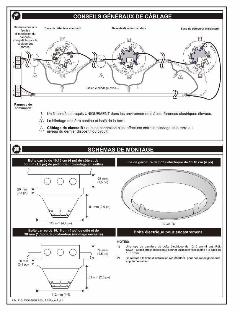
P/N: P-047550-1888 REV: 1.0 Page 4 of 4
Un fil blindé est requis UNIQUEMENT dans les environnements à interférences électriques élevées.
Le blindage doit être continu et isolé de la terre.
Câblage de classe B : aucune connexion n’est effectuée entre le blindage et la terre au niveau du dernier dispositif du circuit.
Panneau de commande
Isoler le blindage avec
112 mm (4,4 po)
38 mm(1,5 po)
51 mm (2,0 po)
20 mm(0,8 po)
Boîte carrée de 10,16 cm (4 po) de côté et de38 mm (1,5 po) de profondeur (montage en saillie)
38 mm(1,5 po)
112 mm (4,4)
51 mm (2,0 po)
20 mm(0,8 po)
Boîte carrée de 10,16 cm (4 po) de côté et de38 mm (1,5 po) de profondeur (montage encastré)
Jupe de garniture de boîte électrique de 10,16 cm (4 po)
SIGA-TS
1) Une jupe de garniture de boîte électrique de 10,16 cm (4 po) (Réf. SIGA-TS) doit être installée pour donner un aspect final soigné à la base de 10,16 mm.
2) Se référer à la fiche d’installation réf. 387056P pour des renseignements supplémentaires.
NOTES:
Boîte électrique pour encastrement
CONSEILS GÉNÉRAUX DE CÂBLAGE
SCHÉMAS DE MONTAGE
3
1.
2
2 2
56
34
17
2
3
56
34
17
2
56
34
17
2
Base de détecteur standard Base de détecteur à relais Base de détecteur à isolateur
+
_
S
+
_
S
Référez-vous aux feuilles
d'installation du panneau
compatible pour le câblage des
bornes.
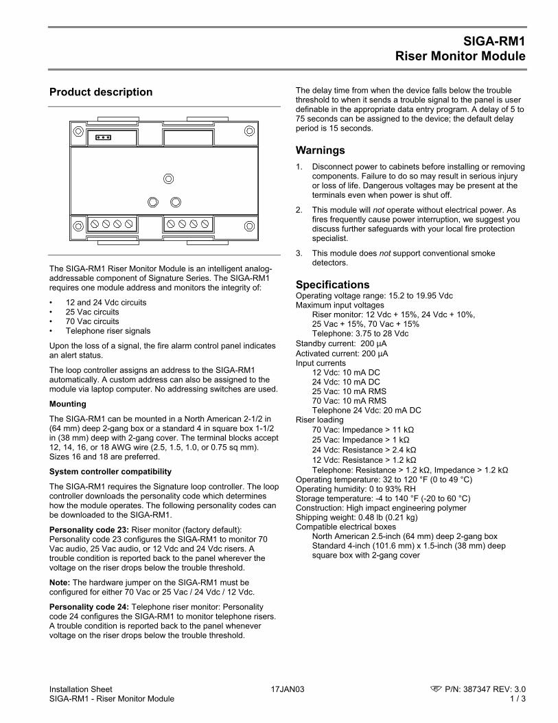
Installation Sheet 17JAN03 P/N: 387347 REV: 3.0SIGA-RM1 - Riser Monitor Module 1 / 3
SIGA-RM1Riser Monitor Module
Product description
The SIGA-RM1 Riser Monitor Module is an intelligent analog-addressable component of Signature Series. The SIGA-RM1requires one module address and monitors the integrity of:
• 12 and 24 Vdc circuits• 25 Vac circuits• 70 Vac circuits• Telephone riser signals
Upon the loss of a signal, the fire alarm control panel indicatesan alert status.
The loop controller assigns an address to the SIGA-RM1automatically. A custom address can also be assigned to themodule via laptop computer. No addressing switches are used.
Mounting
The SIGA-RM1 can be mounted in a North American 2-1/2 in(64 mm) deep 2-gang box or a standard 4 in square box 1-1/2in (38 mm) deep with 2-gang cover. The terminal blocks accept12, 14, 16, or 18 AWG wire (2.5, 1.5, 1.0, or 0.75 sq mm).Sizes 16 and 18 are preferred.
System controller compatibility
The SIGA-RM1 requires the Signature loop controller. The loopcontroller downloads the personality code which determineshow the module operates. The following personality codes canbe downloaded to the SIGA-RM1.
Personality code 23: Riser monitor (factory default):Personality code 23 configures the SIGA-RM1 to monitor 70Vac audio, 25 Vac audio, or 12 Vdc and 24 Vdc risers. Atrouble condition is reported back to the panel wherever thevoltage on the riser drops below the trouble threshold.
Note: The hardware jumper on the SIGA-RM1 must beconfigured for either 70 Vac or 25 Vac / 24 Vdc / 12 Vdc.
Personality code 24: Telephone riser monitor: Personalitycode 24 configures the SIGA-RM1 to monitor telephone risers.A trouble condition is reported back to the panel whenevervoltage on the riser drops below the trouble threshold.
The delay time from when the device falls below the troublethreshold to when it sends a trouble signal to the panel is userdefinable in the appropriate data entry program. A delay of 5 to75 seconds can be assigned to the device; the default delayperiod is 15 seconds.
Warnings1. Disconnect power to cabinets before installing or removing
components. Failure to do so may result in serious injuryor loss of life. Dangerous voltages may be present at theterminals even when power is shut off.
2. This module will not operate without electrical power. Asfires frequently cause power interruption, we suggest youdiscuss further safeguards with your local fire protectionspecialist.
3. This module does not support conventional smokedetectors.
SpecificationsOperating voltage range: 15.2 to 19.95 VdcMaximum input voltages
Riser monitor: 12 Vdc + 15%, 24 Vdc + 10%,25 Vac + 15%, 70 Vac + 15%Telephone: 3.75 to 28 Vdc
Standby current: 200 µAActivated current: 200 µAInput currents
12 Vdc: 10 mA DC24 Vdc: 10 mA DC25 Vac: 10 mA RMS70 Vac: 10 mA RMSTelephone 24 Vdc: 20 mA DC
Riser loading70 Vac: Impedance > 11 kΩ25 Vac: Impedance > 1 kΩ24 Vdc: Resistance > 2.4 kΩ12 Vdc: Resistance > 1.2 kΩTelephone: Resistance > 1.2 kΩ, Impedance > 1.2 kΩ
Operating temperature: 32 to 120 °F (0 to 49 °C)Operating humidity: 0 to 93% RHStorage temperature: -4 to 140 °F (-20 to 60 °C)Construction: High impact engineering polymerShipping weight: 0.48 lb (0.21 kg)Compatible electrical boxes
North American 2.5-inch (64 mm) deep 2-gang boxStandard 4-inch (101.6 mm) x 1.5-inch (38 mm) deepsquare box with 2-gang cover
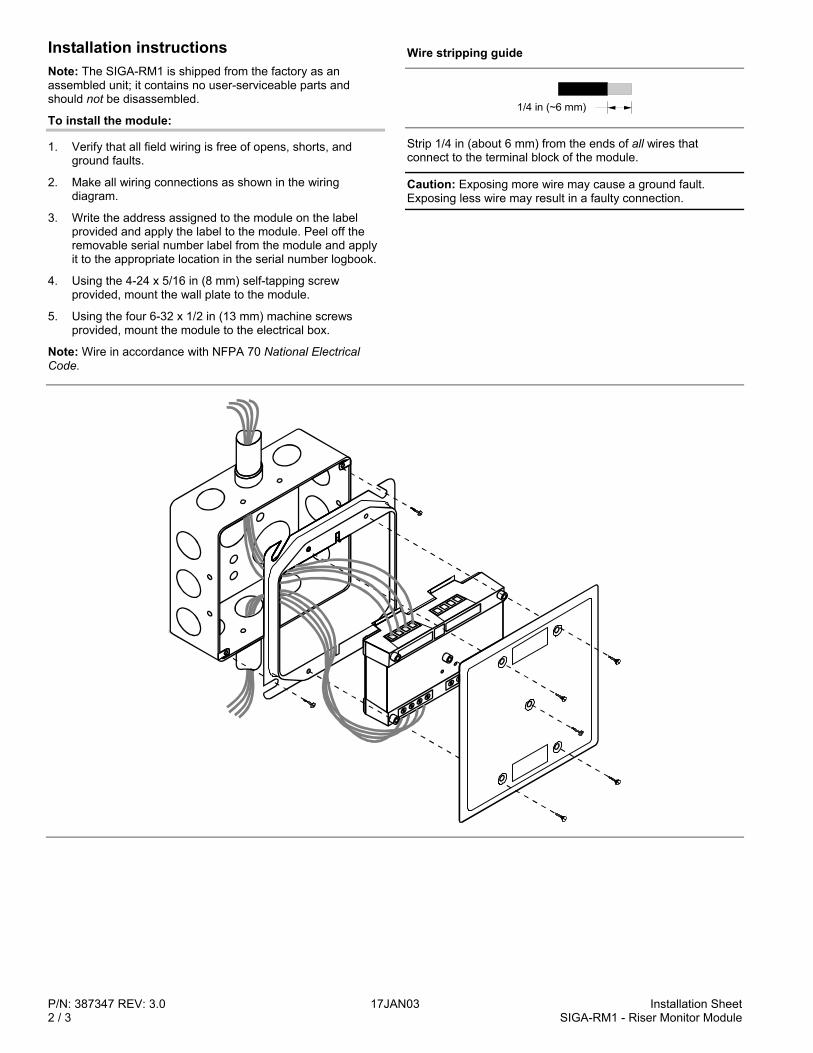
P/N: 387347 REV: 3.0 17JAN03 Installation Sheet2 / 3 SIGA-RM1 - Riser Monitor Module
Installation instructionsNote: The SIGA-RM1 is shipped from the factory as anassembled unit; it contains no user-serviceable parts andshould not be disassembled.
To install the module:
1. Verify that all field wiring is free of opens, shorts, andground faults.
2. Make all wiring connections as shown in the wiringdiagram.
3. Write the address assigned to the module on the labelprovided and apply the label to the module. Peel off theremovable serial number label from the module and applyit to the appropriate location in the serial number logbook.
4. Using the 4-24 x 5/16 in (8 mm) self-tapping screwprovided, mount the wall plate to the module.
5. Using the four 6-32 x 1/2 in (13 mm) machine screwsprovided, mount the module to the electrical box.
Note: Wire in accordance with NFPA 70 National ElectricalCode.
Wire stripping guide
1/4 in (~6 mm)
Strip 1/4 in (about 6 mm) from the ends of all wires thatconnect to the terminal block of the module.
Caution: Exposing more wire may cause a ground fault.Exposing less wire may result in a faulty connection.
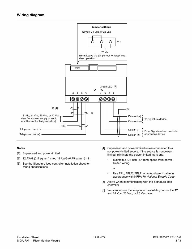
Installation Sheet 17JAN03 P/N: 387347 REV: 3.0SIGA-RM1 - Riser Monitor Module 3 / 3
Wiring diagram
12345678
Data out (-)
Data out (+)
Data in (-)
Data in (+)From Signature loop controlleror previous device
To Signature device12 Vdc, 24 Vdc, 25 Vac, or 70 Vac riser from power supply or audio amplifier (not polarity sensitive)
Telephone riser (+)
Telephone riser (-)
12 Vdc, 24 Vdc, or 25 Vac
70 Vac
JP1
Jumper settings
Note: Leave the jumper out for telephone riser operation.
[2] [3][4]
Green LED
[1] [2]
[5]
[6]
Notes
[1] Supervised and power-limited
[2] 12 AWG (2.5 sq mm) max; 18 AWG (0.75 sq mm) min
[3] See the Signature loop controller installation sheet forwiring specifications
[4] Supervised and power-limited unless connected to anonpower-limited source. If the source is nonpower-limited, eliminate the power-limited mark and:
• Maintain a 1/4 inch (6.4 mm) space from power-limited wiring
or
• Use FPL, FPLR, FPLP, or an equivalent cable inaccordance with NFPA 70 National Electric Code
[5] Active when communicating with the Signature loopcontroller
[6] You cannot use the telephone riser while you use the 12and 24 Vdc, 25 Vac, or 70 Vac riser

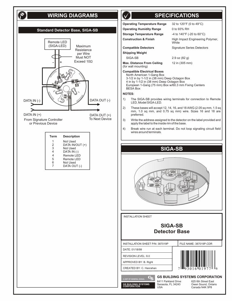
SPECIFICATIONS
SIGA-SB
WIRING DIAGRAMS
56
34
17
2
DATA OUT (-)
DATA OUT (+)To Next DeviceFrom Signature Controller
or Previous Device
DATA IN (-)
DATA IN (+)
Remote LED(SIGA-LED) Maximum
Resistanceper Wire
Must NOTExceed 10Ω- +
Standard Detector Base, SIGA-SB
Operating Temperature Range 32 to 120°F (0 to 49°C)
Operating Humidity Range 0 to 93% RH
Storage Temperature Range -4 to 140°F (-20 to 60°C)
Construction & Finish High Impact Engineering Polymer, White
Compatible Detectors Signature Series Detectors
Shipping Weight
SIGA-SB 2.9 oz (82 g)
Max. Distance From Ceiling 12 in (305 mm)(for wall mounting)
Compatible Electrical BoxesNorth American 1-Gang Box3-1/2 in by 1-1/2 in (38 mm) Deep Octagon Box4 in by 1-1/2 in (38 mm) Deep Octagon BoxEuropean 1-Gang (75 mm) Box w/60.3 mm Fixing CentersBESA Box
NOTES:
1) The SIGA-SB provides wiring terminals for connection to Remote LED, Model SIGA-LED.
2) These bases will accept 12, 14, 16, and 18 AWG (2.05 sq mm, 1.5 sq mm, 1.0 sq mm, and 0.75 sq mm) wire. Sizes 16 and 18 are preferred.
3) Write the address assigned to the detector on the label provided and apply the label to the inside rim of the base.
4) Break wire run at each terminal. Do not loop signaling circuit field wires around terminals.
Term
1 Not Used
4
45
DATA IN (-)
Remote LEDRemote LED
7 DATA OUT (-)
2 DATA IN/OUT (+)3 Not Used
6 Not Used
Description
INSTALLATION SHEET
INSTALLATION SHEET P/N: 387019P
REVISION LEVEL: 8.0
FILE NAME: 387019P.CDR
SIGA-SBDetector Base
DATE: 01/18/99
CREATED BY: C. Hanrahan
APPROVED BY: B. Right
GS BUILDING SYSTEMSCORPORATION
A UNIT OF GENERAL SIGNALGS BUILDING SYSTEMS CORPORATION6411 Parkland DriveSarasota, FL 34243USA
625 6th Street EastOwen Sound, OntarioCanada N4K 5P8
7 69 3 0 1 6 0 1 9 7 7
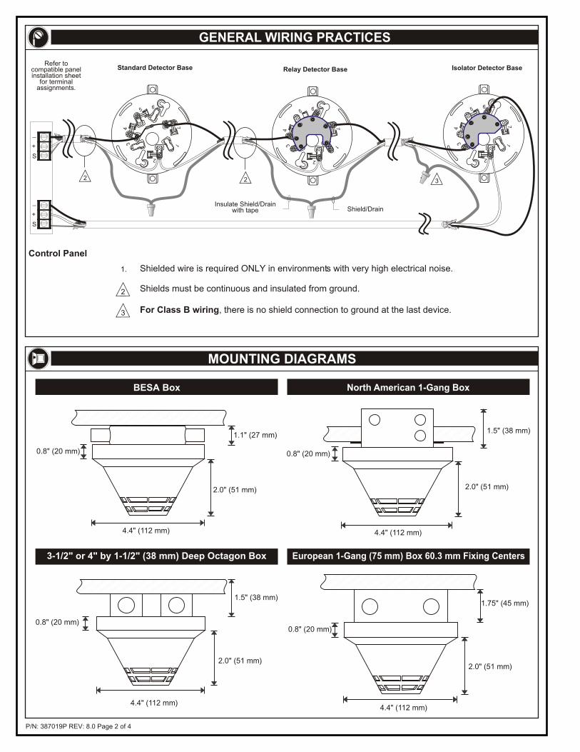
P/N: 387019P REV: 8.0 Page 2 of 4
GENERAL WIRING PRACTICES
MOUNTING DIAGRAMS
1.1" (27 mm)
2.0" (51 mm)
4.4" (112 mm)
0.8" (20 mm)
4.4" (112 mm)
1.5" (38 mm)
2.0" (51 mm)
0.8" (20 mm)
BESA Box North American 1-Gang Box
4.4" (112 mm)
1.5" (38 mm)
2.0" (51 mm)
0.8" (20 mm)
4.4" (112 mm)
1.75" (45 mm)
2.0" (51 mm)
0.8" (20 mm)
3-1/2" or 4" by 1-1/2" (38 mm) Deep Octagon Box European 1-Gang (75 mm) Box 60.3 mm Fixing Centers
For Class B wiring, there is no shield connection to ground at the last device.
Control Panel
3
1.
2
Standard Detector Base
2
Relay Detector Base
Insulate Shield/Drainwith tape Shield/Drain
2
56
34
17
2
Isolator Detector Base
3
56
34
17
2
56
34
17
2
Shields must be continuous and insulated from ground.
Shielded wire is required ONLY in environments with very high electrical noise.
+
_
S
+
_
S
Refer to compatible panelinstallation sheet
for terminalassignments.
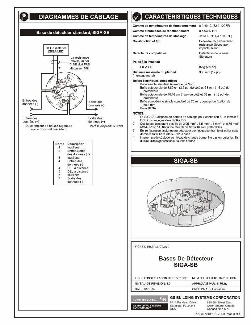
GS BUILDING SYSTEMSCORPORATION
A UNIT OF GENERAL SIGNALGS BUILDING SYSTEMS CORPORATION6411 Parkland DriveSarasota, FL 34243USA
625 6th Street EastOwen Sound, OntarioCanada N4K 5P8
DATE: 01/18/99
FICHE D’INSTALLATION :
FICHE D’INSTALLATION RÉF.: 387019P
NIVEAU DE RÉVISION: 8.0
NOM DU FICHIER: 387019P.CDR
CRÉÉ PAR: C. Hanrahan
APPROUVÉ PAR: B. Right
Bases De DétecteurSIGA-SB
SIGA-SB
Gamme de températures de fonctionnement 0 à 49 ºC (32 à 120 ºF)
Gamme d’humidités de fonctionnement 0 à 93 % HR
Gamme de températures de stockage -20 à 60 ºC (-4 à 140 ºF)
Construction et fini Polymère technique avecrésistance élevée aux impacts, blanc
Détecteurs compatibles Détecteurs de la série Signature
Poids à la livraison
SIGA-SB 82 g (2,9 oz)
Distance maximale du plafond 305 mm (12 po)(montage mural)
Boîtes électriques compatiblesBoîte simple standard Amérique du NordBoîte octogonale de 8,89 cm (3,5 po) de côté et 38 mm (1,5 po) de profondeurBoîte octogonale de 10,16 cm (4 po) de côté et 38 mm (1,5 po) de profondeurBoîte européenne simple standard de 75 mm, centres de fixation de 60,3 mmBoîte BESA
NOTES:1) Le SIGA-SB dispose de bornes de câblage pour connexion à un témoin à
DEL à distance, modèle SIGA-LED. 2 2 2 22) Ces bases acceptent des fils de 2,05 mm , 1,5 mm , 1 mm et 0,75 mm
(AWG nº 12, 14, 16 ou 18). Des fils de 16 ou 18 sont préférables.3) Écrire l’adresse assignée au détecteur sur l’étiquette fournie et coller cette
dernière sur le bord intérieur de la base.4) Interrompre le câblage au niveau de chaque borne. Ne pas enrouler les fils
du circuit de signalisation autour de bornes.Borne Description
1 Inutilisée2 Entrée/Sortie
des données (+)3 Inutilisée4 Entrée des
données (-)4 DEL à distance5 DEL à distance6 Inutilisée7 Sortie des
données (-)
56
34
17
2
DEL à distance(SIGA-LED)
La résistancemaximum parfil NE doit PAS
dépasser 10Ω- +
Entrée des données (-)
Entrée des données (+)
Du contrôleur de boucle Signatureou du dispositif précédent
Vers le dispositif suivant
Sortie des données (-)
Sortie des données (+)
DIAGRAMMES DE CÂBLAGE
Base de détecteur standard, SIGA-SB
CARACTÉRISTIQUES TECHNIQUES
P/N: 387019P REV: 8.0 Page 3 of 4

P/N: 387019P REV: 8.0 Page 4 of 4
27 mm(1,1 po)
51 mm (2,0 po)
112 mm (4,4 po)
20 mm (0,8 po)
112 mm (4,4 po)
38 mm(1,5 po)
51 mm (2,0 po)
20 mm (0,8 po)
112 mm (4,4 po)
38 mm(1,5 po)
51 mm (2,0 po)
20 mm (0,8 po)
112 mm (4,4 po)
45 mm (1,75 po)
51 mm (2,0 po)
20 mm (0,8 po)
Boîte BESA
Boîte octogonale de 8,89 cm (3,5 po) ou de 10,16 cm (4 po)de côté et de 38 mm (1,5 po) de profondeur
Boîte européenne simple standard de 75 mm,centres de fixation de 60,3 mm
CONSEILS GÉNÉRAUX DE CÂBLAGE
SCHÉMAS DE MONTAGE
Boîte simple standard Amérique du Nord
Un fil blindé est requis UNIQUEMENT dans les environnements à interférences électriques élevées.
Le blindage doit être continu et isolé de la terre.
Câblage de classe B : aucune connexion n’est effectuée entre le blindage et la terre au niveau du dernier dispositif du circuit.
Panneau de commande
Isoler le blindage avec
3
1.
2
2 2
56
34
17
2
3
56
34
17
2
56
34
17
2
Base de détecteur standard Base de détecteur à relais Base de détecteur à isolateur
+
_
S
+
_
S
Référez-vous aux feuilles
d'installation du panneau
compatible pour le câblage des
bornes.
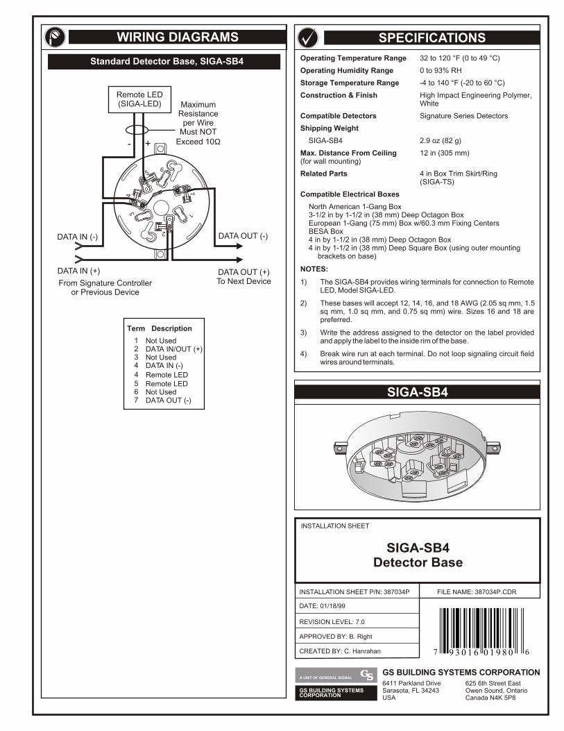
Operating Temperature Range 32 to 120 °F (0 to 49 °C)
Operating Humidity Range 0 to 93% RH
Storage Temperature Range -4 to 140 °F (-20 to 60 °C)
Construction & Finish High Impact Engineering Polymer, White
Compatible Detectors Signature Series Detectors
Shipping Weight
SIGA-SB4 2.9 oz (82 g)
Max. Distance From Ceiling 12 in (305 mm)(for wall mounting)
Related Parts 4 in Box Trim Skirt/Ring(SIGA-TS)
Compatible Electrical Boxes
North American 1-Gang Box3-1/2 in by 1-1/2 in (38 mm) Deep Octagon BoxEuropean 1-Gang (75 mm) Box w/60.3 mm Fixing CentersBESA Box4 in by 1-1/2 in (38 mm) Deep Octagon Box4 in by 1-1/2 in (38 mm) Deep Square Box (using outer mounting
brackets on base)
NOTES:
1) The SIGA-SB4 provides wiring terminals for connection to Remote LED, Model SIGA-LED.
2) These bases will accept 12, 14, 16, and 18 AWG (2.05 sq mm, 1.5 sq mm, 1.0 sq mm, and 0.75 sq mm) wire. Sizes 16 and 18 are preferred.
3) Write the address assigned to the detector on the label provided and apply the label to the inside rim of the base.
4) Break wire run at each terminal. Do not loop signaling circuit field wires around terminals.
SIGA-SB4
Standard Detector Base, SIGA-SB4
SPECIFICATIONSWIRING DIAGRAMS
56
34
17
2
DATA OUT (-)
DATA OUT (+)To Next DeviceFrom Signature Controller
or Previous Device
DATA IN (-)
DATA IN (+)
Remote LED(SIGA-LED) Maximum
Resistanceper Wire
Must NOTExceed 10Ω- +
Term
1 Not Used
4
45
DATA IN (-)
Remote LEDRemote LED
7 DATA OUT (-)
2 DATA IN/OUT (+)3 Not Used
6 Not Used
Description
INSTALLATION SHEET
INSTALLATION SHEET P/N: 387034P
REVISION LEVEL: 7.0
FILE NAME: 387034P.CDR
SIGA-SB4Detector Base
DATE: 01/18/99
CREATED BY: C. Hanrahan
APPROVED BY: B. Right
GS BUILDING SYSTEMSCORPORATION
A UNIT OF GENERAL SIGNALGS BUILDING SYSTEMS CORPORATION6411 Parkland DriveSarasota, FL 34243USA
625 6th Street EastOwen Sound, OntarioCanada N4K 5P8
7 69 3 0 1 6 0 1 9 8 0
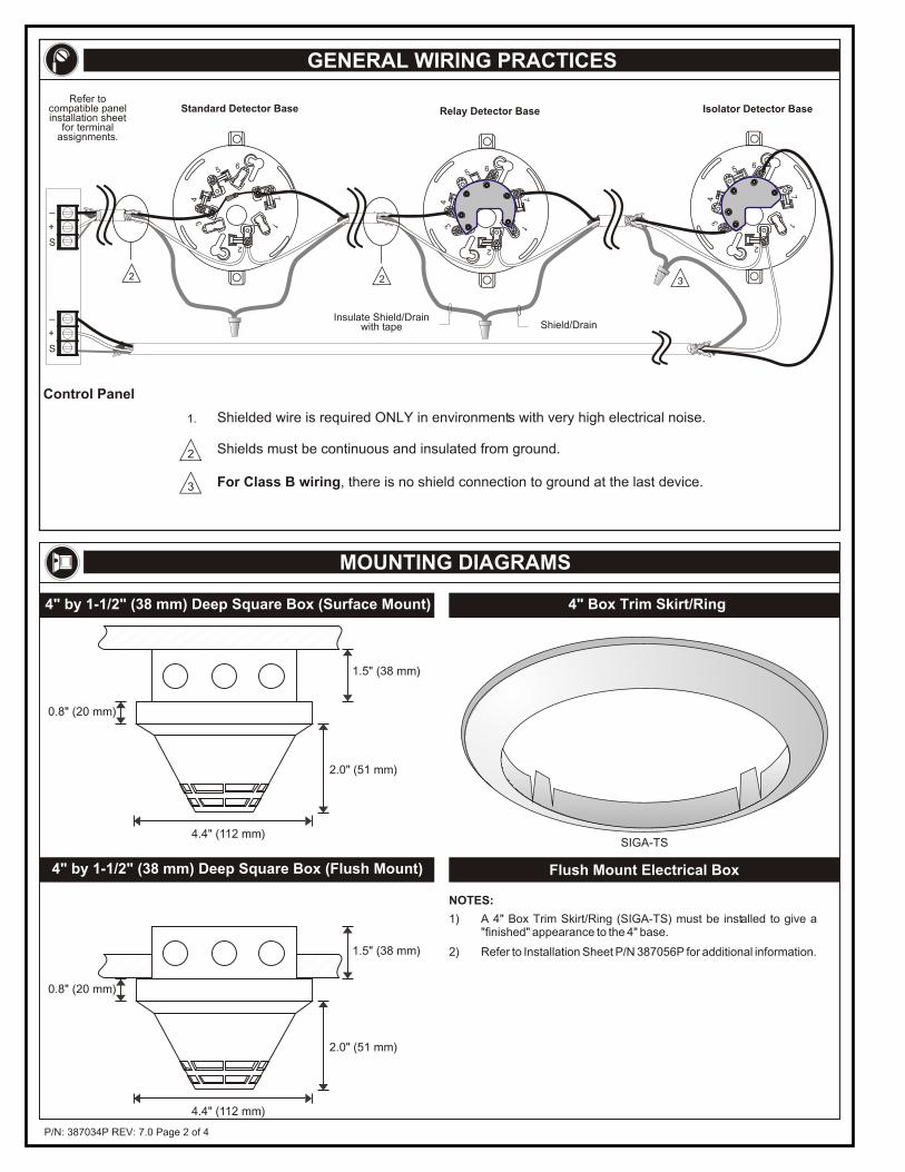
P/N: 387034P REV: 7.0 Page 2 of 4
GENERAL WIRING PRACTICES
MOUNTING DIAGRAMS
4.4" (112 mm)
1.5" (38 mm)
2.0" (51 mm)
0.8" (20 mm)
1.5" (38 mm)
4.4" (112 mm)
2.0" (51 mm)
0.8" (20 mm)
4" by 1-1/2" (38 mm) Deep Square Box (Flush Mount)
4" by 1-1/2" (38 mm) Deep Square Box (Surface Mount) 4" Box Trim Skirt/Ring
Flush Mount Electrical Box
1) A 4" Box Trim Skirt/Ring (SIGA-TS) must be installed to give a "finished" appearance to the 4" base.
2) Refer to Installation Sheet P/N 387056P for additional information.
NOTES:
SIGA-TS
For Class B wiring, there is no shield connection to ground at the last device.
Control Panel
3
1.
2
Standard Detector Base
2
Relay Detector Base
Insulate Shield/Drainwith tape Shield/Drain
2
56
34
17
2
Isolator Detector Base
3
56
34
17
2
56
34
17
2
Shields must be continuous and insulated from ground.
Shielded wire is required ONLY in environments with very high electrical noise.
+
_
S
+
_
S
Refer to compatible panelinstallation sheet
for terminalassignments.
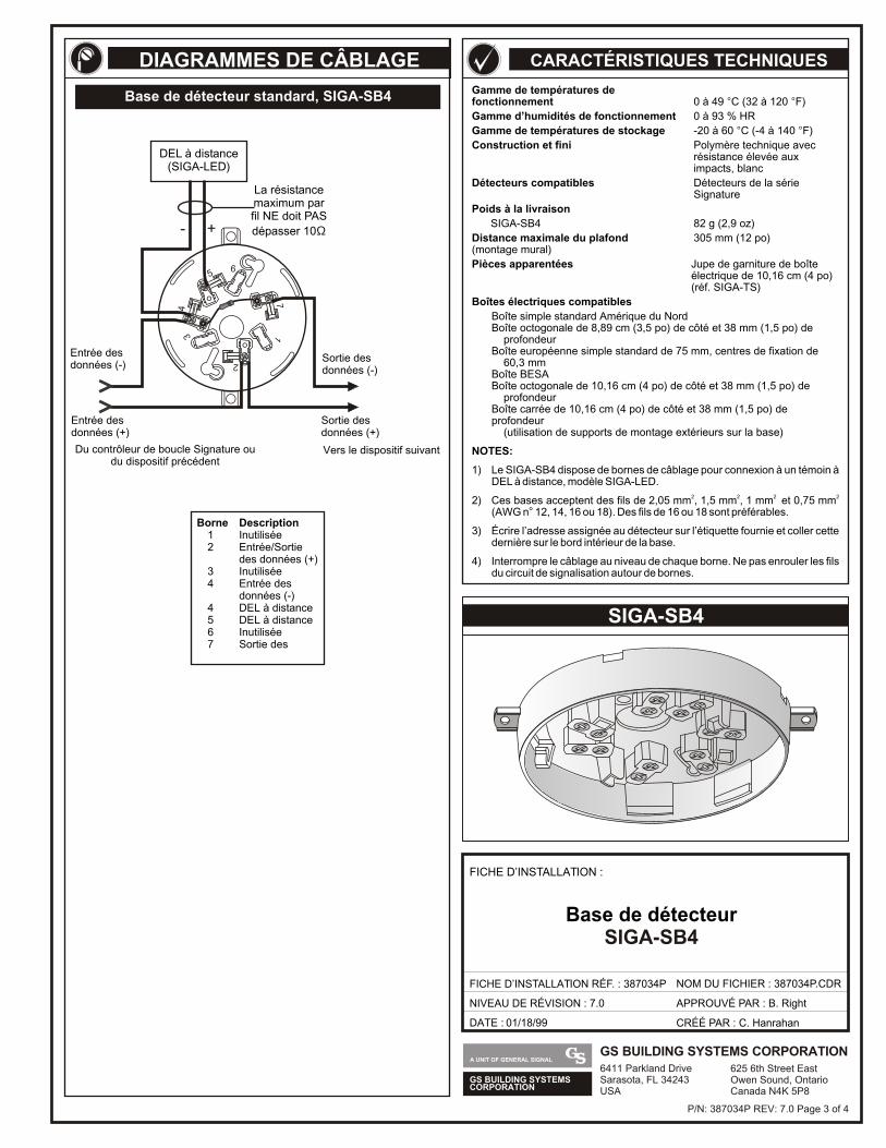
GS BUILDING SYSTEMSCORPORATION
A UNIT OF GENERAL SIGNALGS BUILDING SYSTEMS CORPORATION6411 Parkland DriveSarasota, FL 34243USA
625 6th Street EastOwen Sound, OntarioCanada N4K 5P8
Gamme de températures de fonctionnement 0 à 49 C (32 à 120 F)
Gamme d’humidités de fonctionnement 0 à 93 % HR
Gamme de températures de stockage -20 à 60 C (-4 à 140 F)
Construction et fini Polymère technique avec résistance élevée aux impacts, blanc
Détecteurs compatibles Détecteurs de la sérieSignature
Poids à la livraison
SIGA-SB4 82 g (2,9 oz)
Distance maximale du plafond 305 mm (12 po)(montage mural)
Pièces apparentées Jupe de garniture de boîteélectrique de 10,16 cm (4 po) (réf. SIGA-TS)
Boîtes électriques compatibles
Boîte simple standard Amérique du NordBoîte octogonale de 8,89 cm (3,5 po) de côté et 38 mm (1,5 po) de profondeurBoîte européenne simple standard de 75 mm, centres de fixation de 60,3 mmBoîte BESABoîte octogonale de 10,16 cm (4 po) de côté et 38 mm (1,5 po) de profondeurBoîte carrée de 10,16 cm (4 po) de côté et 38 mm (1,5 po) de profondeur (utilisation de supports de montage extérieurs sur la base)
NOTES:
1) Le SIGA-SB4 dispose de bornes de câblage pour connexion à un témoin à DEL à distance, modèle SIGA-LED.
2 2 2 2 2) Ces bases acceptent des fils de 2,05 mm , 1,5 mm , 1 mm et 0,75 mm(AWG n 12, 14, 16 ou 18). Des fils de 16 ou 18 sont préférables.
3) Écrire l’adresse assignée au détecteur sur l’étiquette fournie et coller cette dernière sur le bord intérieur de la base.
4) Interrompre le câblage au niveau de chaque borne. Ne pas enrouler les fils du circuit de signalisation autour de bornes.
° °
° °
°
SIGA-SB4
CARACTÉRISTIQUES TECHNIQUES
DATE : 01/18/99
FICHE D’INSTALLATION :
FICHE D’INSTALLATION RÉF. : 387034P NOM DU FICHIER : 387034P.CDR
NIVEAU DE RÉVISION : 7.0
CRÉÉ PAR : C. Hanrahan
APPROUVÉ PAR : B. Right
Base de détecteurSIGA-SB4
DIAGRAMMES DE CÂBLAGE
Base de détecteur standard, SIGA-SB4
Borne Description1 Inutilisée2 Entrée/Sortie
des données (+)3 Inutilisée4 Entrée des
données (-)4 DEL à distance5 DEL à distance6 Inutilisée7 Sortie des
56
34
17
2
- +
DEL à distance(SIGA-LED)
La résistancemaximum parfil NE doit PAS
dépasser 10Ω
Entrée des données (-)
Entrée des données (+)
Du contrôleur de boucle Signature ou du dispositif précédent
Vers le dispositif suivant
Sortie des données (-)
Sortie des données (+)
P/N: 387034P REV: 7.0 Page 3 of 4
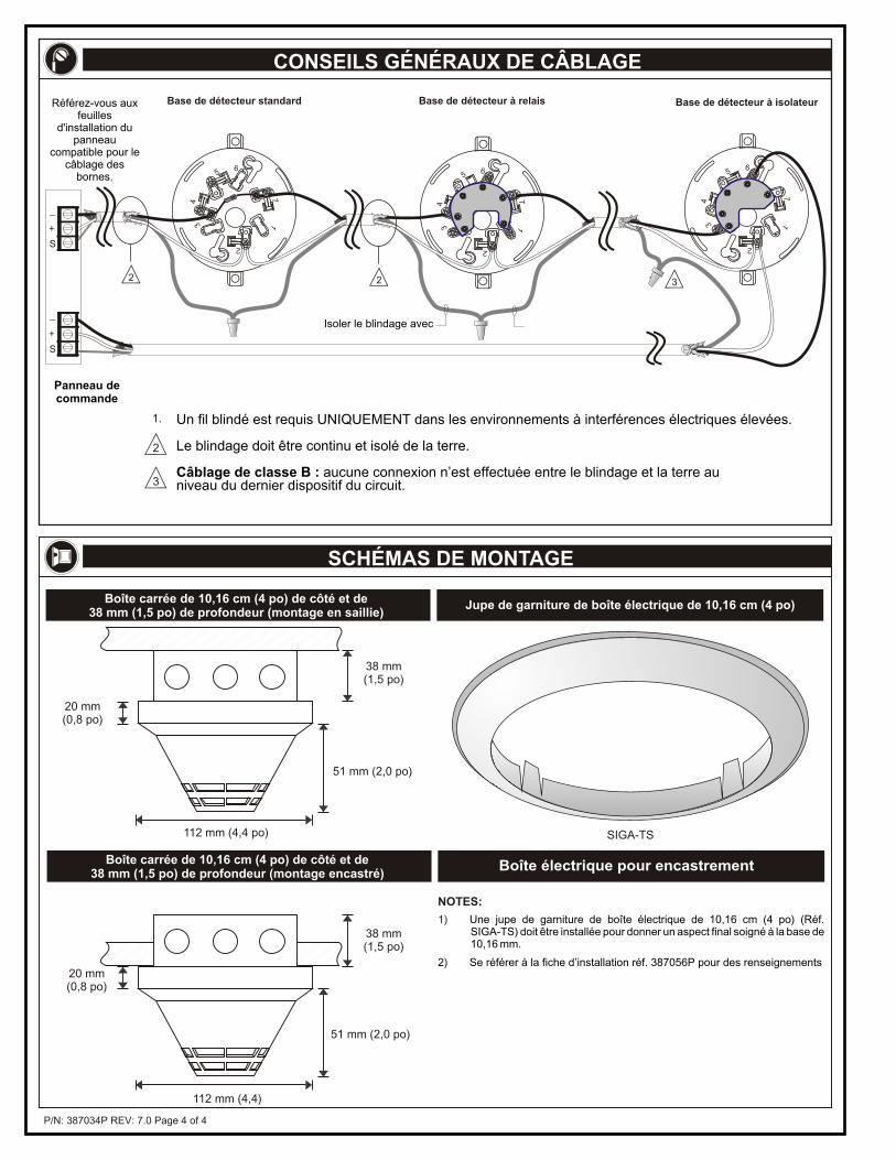
P/N: 387034P REV: 7.0 Page 4 of 4
112 mm (4,4 po)
38 mm(1,5 po)
51 mm (2,0 po)
20 mm(0,8 po)
Boîte carrée de 10,16 cm (4 po) de côté et de38 mm (1,5 po) de profondeur (montage en saillie)
38 mm(1,5 po)
112 mm (4,4)
51 mm (2,0 po)
20 mm(0,8 po)
Boîte carrée de 10,16 cm (4 po) de côté et de38 mm (1,5 po) de profondeur (montage encastré)
Jupe de garniture de boîte électrique de 10,16 cm (4 po)
SIGA-TS
1) Une jupe de garniture de boîte électrique de 10,16 cm (4 po) (Réf. SIGA-TS) doit être installée pour donner un aspect final soigné à la base de 10,16 mm.
2) Se référer à la fiche d’installation réf. 387056P pour des renseignements
NOTES:
Boîte électrique pour encastrement
CONSEILS GÉNÉRAUX DE CÂBLAGE
SCHÉMAS DE MONTAGE
Un fil blindé est requis UNIQUEMENT dans les environnements à interférences électriques élevées.
Le blindage doit être continu et isolé de la terre.
Câblage de classe B : aucune connexion n’est effectuée entre le blindage et la terre au niveau du dernier dispositif du circuit.
Panneau de commande
Isoler le blindage avec
3
1.
2
2 2
56
34
17
2
3
56
34
17
2
56
34
17
2
Base de détecteur standard Base de détecteur à relais Base de détecteur à isolateur
+
_
S
+
_
S
Référez-vous aux feuilles
d'installation du panneau
compatible pour le câblage des
bornes.
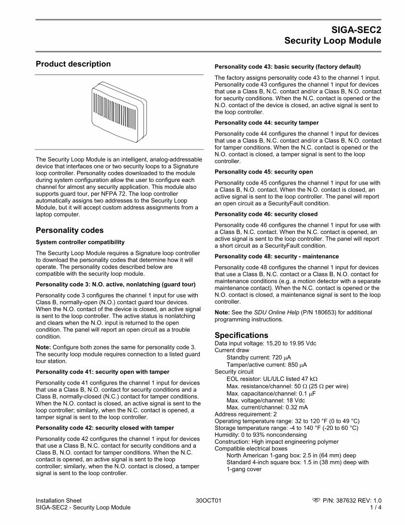
Installation Sheet 30OCT01 P/N: 387632 REV: 1.0SIGA-SEC2 - Security Loop Module 1 / 4
SIGA-SEC2Security Loop Module
Product description
The Security Loop Module is an intelligent, analog-addressabledevice that interfaces one or two security loops to a Signatureloop controller. Personality codes downloaded to the moduleduring system configuration allow the user to configure eachchannel for almost any security application. This module alsosupports guard tour, per NFPA 72. The loop controllerautomatically assigns two addresses to the Security LoopModule, but it will accept custom address assignments from alaptop computer.
Personality codesSystem controller compatibility
The Security Loop Module requires a Signature loop controllerto download the personality codes that determine how it willoperate. The personality codes described below arecompatible with the security loop module.
Personality code 3: N.O. active, nonlatching (guard tour)
Personality code 3 configures the channel 1 input for use withClass B, normally-open (N.O.) contact guard tour devices.When the N.O. contact of the device is closed, an active signalis sent to the loop controller. The active status is nonlatchingand clears when the N.O. input is returned to the opencondition. The panel will report an open circuit as a troublecondition.
Note: Configure both zones the same for personality code 3.The security loop module requires connection to a listed guardtour station.
Personality code 41: security open with tamper
Personality code 41 configures the channel 1 input for devicesthat use a Class B, N.O. contact for security conditions and aClass B, normally-closed (N.C.) contact for tamper conditions.When the N.O. contact is closed, an active signal is sent to theloop controller; similarly, when the N.C. contact is opened, atamper signal is sent to the loop controller.
Personality code 42: security closed with tamper
Personality code 42 configures the channel 1 input for devicesthat use a Class B, N.C. contact for security conditions and aClass B, N.O. contact for tamper conditions. When the N.C.contact is opened, an active signal is sent to the loopcontroller; similarly, when the N.O. contact is closed, a tampersignal is sent to the loop controller.
Personality code 43: basic security (factory default)
The factory assigns personality code 43 to the channel 1 input.Personality code 43 configures the channel 1 input for devicesthat use a Class B, N.C. contact and/or a Class B, N.O. contactfor security conditions. When the N.C. contact is opened or theN.O. contact of the device is closed, an active signal is sent tothe loop controller.
Personality code 44: security tamper
Personality code 44 configures the channel 1 input for devicesthat use a Class B, N.C. contact and/or a Class B, N.O. contactfor tamper conditions. When the N.C. contact is opened or theN.O. contact is closed, a tamper signal is sent to the loopcontroller.
Personality code 45: security open
Personality code 45 configures the channel 1 input for use witha Class B, N.O. contact. When the N.O. contact is closed, anactive signal is sent to the loop controller. The panel will reportan open circuit as a SecurityFault condition.
Personality code 46: security closed
Personality code 46 configures the channel 1 input for use witha Class B, N.C. contact. When the N.C. contact is opened, anactive signal is sent to the loop controller. The panel will reporta short circuit as a SecurityFault condition.
Personality code 48: security - maintenance
Personality code 48 configures the channel 1 input for devicesthat use a Class B, N.C. contact or a Class B, N.O. contact formaintenance conditions (e.g. a motion detector with a separatemaintenance contact). When the N.C. contact is opened or theN.O. contact is closed, a maintenance signal is sent to the loopcontroller.
Note: See the SDU Online Help (P/N 180653) for additionalprogramming instructions.
SpecificationsData input voltage: 15.20 to 19.95 VdcCurrent draw
Standby current: 720 ATamper/active current: 850 A
Security circuitEOL resistor: UL/ULC listed 47 kMax. resistance/channel: 50 (25 per wire)Max. capacitance/channel: 0.1 FMax. voltage/channel: 18 VdcMax. current/channel: 0.32 mA
Address requirement: 2Operating temperature range: 32 to 120 °F (0 to 49 °C)Storage temperature range: -4 to 140 °F (-20 to 60 °C)Humidity: 0 to 93% noncondensingConstruction: High impact engineering polymerCompatible electrical boxes
North American 1-gang box: 2.5 in (64 mm) deepStandard 4-inch square box: 1.5 in (38 mm) deep with1-gang cover
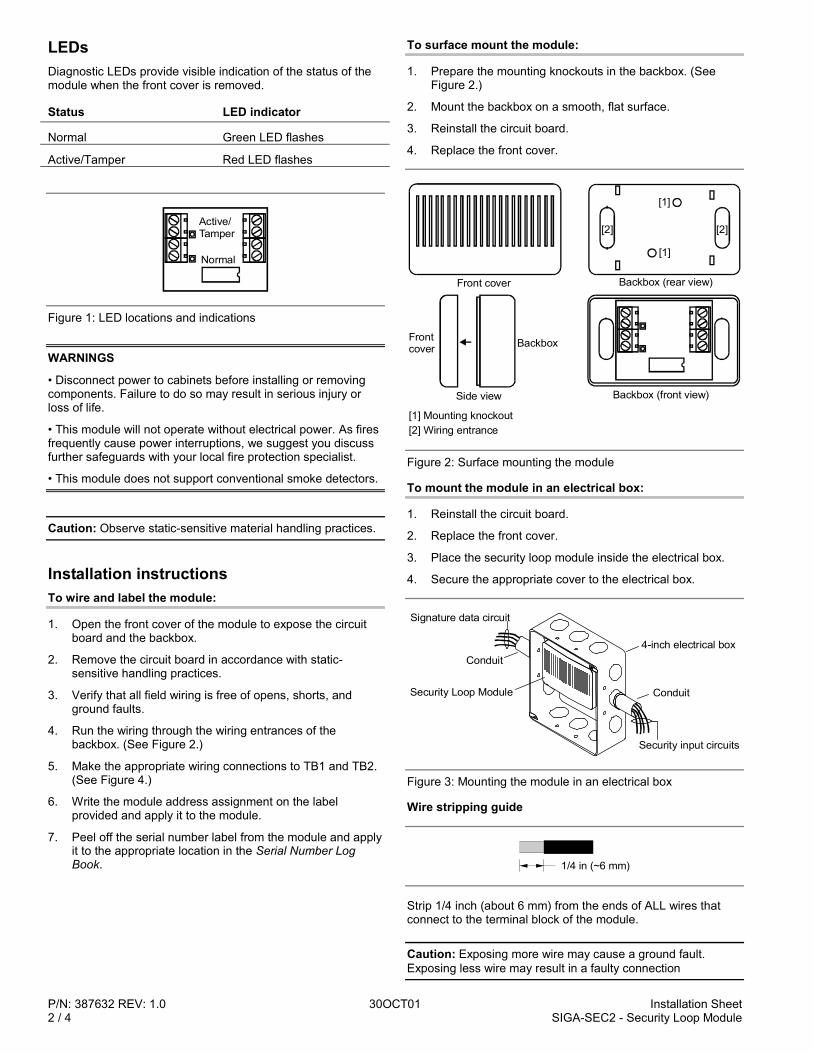
P/N: 387632 REV: 1.0 30OCT01 Installation Sheet2 / 4 SIGA-SEC2 - Security Loop Module
LEDsDiagnostic LEDs provide visible indication of the status of themodule when the front cover is removed.
Status LED indicator
Normal Green LED flashes
Active/Tamper Red LED flashes
Normal
Active/Tamper
Figure 1: LED locations and indications
WARNINGS
• Disconnect power to cabinets before installing or removingcomponents. Failure to do so may result in serious injury orloss of life.
• This module will not operate without electrical power. As firesfrequently cause power interruptions, we suggest you discussfurther safeguards with your local fire protection specialist.
• This module does not support conventional smoke detectors.
Caution: Observe static-sensitive material handling practices.
Installation instructionsTo wire and label the module:
1. Open the front cover of the module to expose the circuitboard and the backbox.
2. Remove the circuit board in accordance with static-sensitive handling practices.
3. Verify that all field wiring is free of opens, shorts, andground faults.
4. Run the wiring through the wiring entrances of thebackbox. (See Figure 2.)
5. Make the appropriate wiring connections to TB1 and TB2.(See Figure 4.)
6. Write the module address assignment on the labelprovided and apply it to the module.
7. Peel off the serial number label from the module and applyit to the appropriate location in the Serial Number LogBook.
To surface mount the module:
1. Prepare the mounting knockouts in the backbox. (SeeFigure 2.)
2. Mount the backbox on a smooth, flat surface.
3. Reinstall the circuit board.
4. Replace the front cover.
[1] Mounting knockout[2] Wiring entrance
[1]
[2]
[1]
[2]
Backbox (front view)
Backbox (rear view)
Side view
Front cover
Frontcover Backbox
Figure 2: Surface mounting the module
To mount the module in an electrical box:
1. Reinstall the circuit board.
2. Replace the front cover.
3. Place the security loop module inside the electrical box.
4. Secure the appropriate cover to the electrical box.
4-inch electrical box
Security Loop Module Conduit
Security input circuits
Signature data circuit
Conduit
Figure 3: Mounting the module in an electrical box
Wire stripping guide
1/4 in (~6 mm)
Strip 1/4 inch (about 6 mm) from the ends of ALL wires thatconnect to the terminal block of the module.
Caution: Exposing more wire may cause a ground fault.Exposing less wire may result in a faulty connection
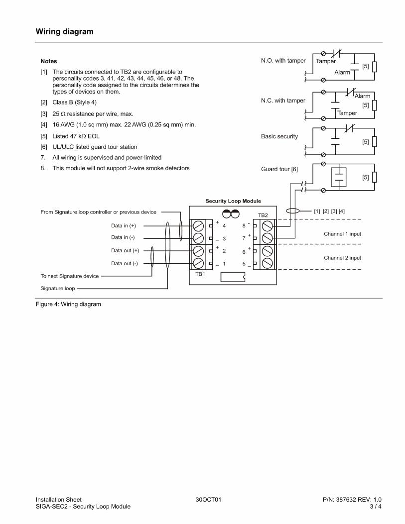
Installation Sheet 30OCT01 P/N: 387632 REV: 1.0SIGA-SEC2 - Security Loop Module 3 / 4
Wiring diagram
Channel 2 input
Channel 1 input
Security Loop Module
[1] [2] [3] [4]TB2
8
7
6
5 _
+
+
-
TB1
1
2
3
4
_
+
_
+
From Signature loop controller or previous device
Data in (+)
Data in (-)
Data out (-)
Data out (+)
To next Signature device
Signature loop
Notes[1] The circuits connected to TB2 are configurable to
personality codes 3, 41, 42, 43, 44, 45, 46, or 48. The personality code assigned to the circuits determines the types of devices on them.
[2] Class B (Style 4)
[3] 25 resistance per wire, max.
[4] 16 AWG (1.0 sq mm) max. 22 AWG (0.25 sq mm) min.
[5] Listed 47 k EOL
[6] UL/ULC listed guard tour station
7. All wiring is supervised and power-limited
8. This module will not support 2-wire smoke detectors
Basic security
N.C. with tamper
N.O. with tamper
Guard tour [6]
Tamper
Alarm
Alarm
Tamper
[5]
[5]
[5]
[5]
Figure 4: Wiring diagram

P/N: 387632 REV: 1.0 30OCT01 Installation Sheet4 / 4 SIGA-SEC2 - Security Loop Module
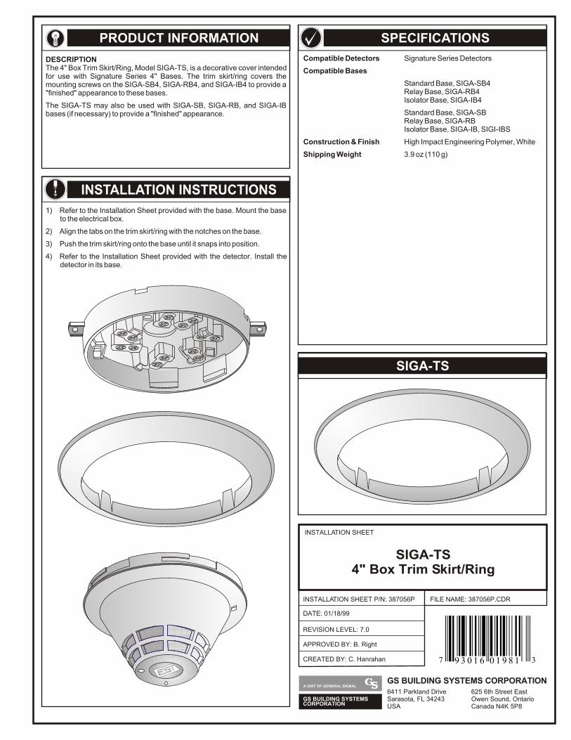
PRODUCT INFORMATION
DESCRIPTIONThe 4" Box Trim Skirt/Ring, Model SIGA-TS, is a decorative cover intended for use with Signature Series 4" Bases. The trim skirt/ring covers the mounting screws on the SIGA-SB4, SIGA-RB4, and SIGA-IB4 to provide a "finished" appearance to these bases.
The SIGA-TS may also be used with SIGA-SB, SIGA-RB, and SIGA-IB bases (if necessary) to provide a "finished" appearance.
1) Refer to the Installation Sheet provided with the base. Mount the base to the electrical box.
2) Align the tabs on the trim skirt/ring with the notches on the base.
3) Push the trim skirt/ring onto the base until it snaps into position.
4) Refer to the Installation Sheet provided with the detector. Install the detector in its base.
INSTALLATION INSTRUCTIONS
SPECIFICATIONS
Compatible Detectors Signature Series Detectors
Compatible Bases
Standard Base, SIGA-SB4Relay Base, SIGA-RB4Isolator Base, SIGA-IB4
Standard Base, SIGA-SBRelay Base, SIGA-RBIsolator Base, SIGA-IB, SIGI-IBS
Construction & Finish High Impact Engineering Polymer, White
Shipping Weight 3.9 oz (110 g)
SIGA-TS
INSTALLATION SHEET
INSTALLATION SHEET P/N: 387056P
REVISION LEVEL: 7.0
FILE NAME: 387056P.CDR
SIGA-TS4" Box Trim Skirt/Ring
DATE: 01/18/99
CREATED BY: C. Hanrahan
APPROVED BY: B. Right
GS BUILDING SYSTEMSCORPORATION
A UNIT OF GENERAL SIGNALGS BUILDING SYSTEMS CORPORATION6411 Parkland DriveSarasota, FL 34243USA
625 6th Street EastOwen Sound, OntarioCanada N4K 5P8
7 39 3 0 1 6 0 1 9 8 1
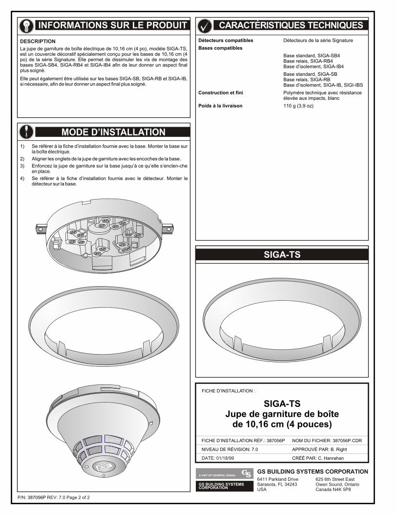
P/N: REV: 7.0 Page 2 of 2387056P
INFORMATIONS SUR LE PRODUIT
DESCRIPTION
La jupe de garniture de boîte électrique de 10,16 cm (4 po), modèle SIGA-TS, est un couvercle décoratif spécialement conçu pour les bases de 10,16 cm (4 po) de la série Signature. Elle permet de dissimuler les vis de montage des bases SIGA-SB4, SIGA-RB4 et SIGA-IB4 afin de leur donner un aspect final plus soigné.
Elle peut également être utilisée sur les bases SIGA-SB, SIGA-RB et SIGA-IB, si nécessaire, afin de leur donner un aspect final plus soigné.
CARACTÉRISTIQUES TECHNIQUES
Détecteurs compatibles Détecteurs de la série Signature
Bases compatibles
Base standard, SIGA-SB4Base relais, SIGA-RB4Base d’isolement, SIGA-IB4
Base standard, SIGA-SBBase relais, SIGA-RBBase d’isolement, SIGA-IB, SIGI-IBS
Construction et fini Polymère technique avec résistanceélevée aux impacts, blanc
Poids à la livraison 110 g (3,9 oz)
SIGA-TSJupe de garniture de boîte
de 10,16 cm (4 pouces)
MODE D’INSTALLATION
1) Se référer à la fiche d’installation fournie avec la base. Monter la base sur la boîte électrique.
2) Aligner les onglets de la jupe de garniture avec les encoches de la base.
3) Enfoncez la jupe de garniture sur la base jusqu’à ce qu’elle s’enclen-che en place.
4) Se référer à la fiche d’installation fournie avec le détecteur. Monter le détecteur sur la base.
GS BUILDING SYSTEMSCORPORATION
A UNIT OF GENERAL SIGNALGS BUILDING SYSTEMS CORPORATION6411 Parkland DriveSarasota, FL 34243USA
625 6th Street EastOwen Sound, OntarioCanada N4K 5P8
DATE: 01/18/99
FICHE D’INSTALLATION :
FICHE D’INSTALLATION RÉF.: 387056P
NIVEAU DE RÉVISION: 7.0
NOM DU FICHIER: 387056P.CDR
CRÉÉ PAR: C. Hanrahan
APPROUVÉ PAR: B. Right
SIGA-TS
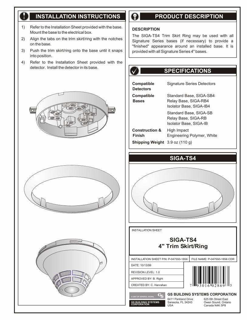
SPECIFICATIONS
PRODUCT DESCRIPTION
DESCRIPTION
The SIGA-TS4 Trim Skirt Ring may be used with all
Signature Series bases (if necessary) to provide a
"finished" appearance around an installed base. It is
provided with all Signature Series 4" bases.
INSTALLATION INSTRUCTIONS
1) Refer to the Installation Sheet provided with the base.
Mount the base to the electrical box.
2) Align the tabs on the trim skirt/ring with the notches
on the base.
3) Push the trim skirt/ring onto the base until it snaps
into position.
4) Refer to the Installation Sheet provided with the
detector. Install the detector in its base.
Compatible Signature Series Detectors
Detectors
Compatible Standard Base, SIGA-SB4
Bases Relay Base, SIGA-RB4
Isolator Base, SIGA-IB4
Standard Base, SIGA-SB
Relay Base, SIGA-RB
Isolator Base, SIGA-IB
Construction & High Impact
Finish Engineering Polymer, White
Shipping Weight 3.9 oz (110 g)
SIGA-TS4
INSTALLATION SHEET
INSTALLATION SHEET P/N: P-047550-1856
REVISION LEVEL: 1.0
FILE NAME: P-047550-1856.CDR
SIGA-TS4 4" Trim Skirt/Ring
DATE: 10/13/99
CREATED BY: C. Hanrahan
APPROVED BY: B. Right
GS BUILDING SYSTEMSCORPORATION
A UNIT OF GENERAL SIGNALGS BUILDING SYSTEMS CORPORATION6411 Parkland DriveSarasota, FL 34243USA
625 6th Street EastOwen Sound, OntarioCanada N4K 5P8
7 39 3 0 1 6 0 2 8 6 9
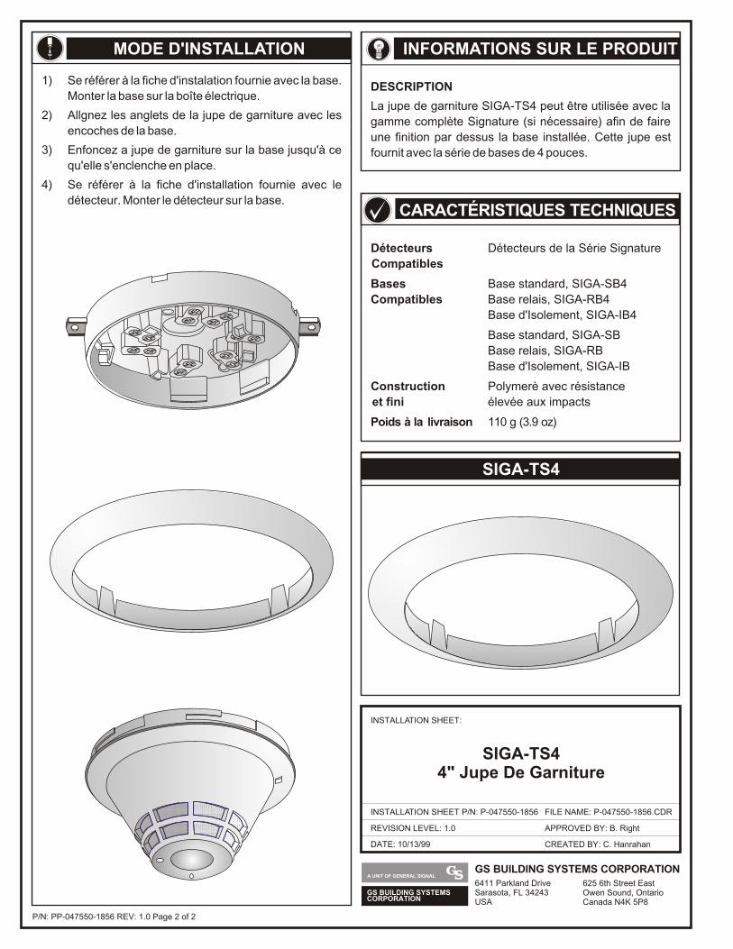
GS BUILDING SYSTEMSCORPORATION
A UNIT OF GENERAL SIGNALGS BUILDING SYSTEMS CORPORATION6411 Parkland DriveSarasota, FL 34243USA
625 6th Street EastOwen Sound, OntarioCanada N4K 5P8
DATE: 10/13/99
INSTALLATION SHEET:
INSTALLATION SHEET P/N: P-047550-1856
REVISION LEVEL: 1.0
FILE NAME: P-047550-1856.CDR
CREATED BY: C. Hanrahan
APPROVED BY: B. Right
SIGA-TS4 4" Jupe De Garniture
CARACTÉRISTIQUES TECHNIQUES
INFORMATIONS SUR LE PRODUIT
DESCRIPTION
La jupe de garniture SIGA-TS4 peut être utilisée avec la
gamme complète Signature (si nécessaire) afin de faire
une finition par dessus la base installée. Cette jupe est
fournit avec la série de bases de 4 pouces.
MODE D'INSTALLATION
1) Se référer à la fiche d'instalation fournie avec la base.
Monter la base sur la boîte électrique.
2) Allgnez les anglets de la jupe de garniture avec les
encoches de la base.
3) Enfoncez a jupe de garniture sur la base jusqu'à ce
qu'elle s'enclenche en place.
4) Se référer à la fiche d'installation fournie avec le
détecteur. Monter le détecteur sur la base.
Détecteurs Détecteurs de la Série Signature
Compatibles
Bases Base standard, SIGA-SB4
Compatibles Base relais, SIGA-RB4
Base d'Isolement, SIGA-IB4
Base standard, SIGA-SB
Base relais, SIGA-RB
Base d'Isolement, SIGA-IB
Construction Polymerè avec résistance
et fini élevée aux impacts
Poids à la livraison 110 g (3.9 oz)
SIGA-TS4
P/N: PP-047550-1856 REV: 1.0 Page 2 of 2
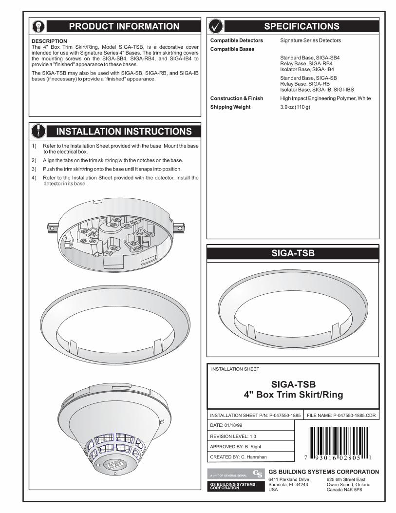
PRODUCT INFORMATION
DESCRIPTIONThe 4" Box Trim Skirt/Ring, Model SIGA-TSB, is a decorative coverintended for use with Signature Series 4" Bases. The trim skirt/ring coversthe mounting screws on the SIGA-SB4, SIGA-RB4, and SIGA-IB4 toprovide a "finished" appearance to these bases.
The SIGA-TSB may also be used with SIGA-SB, SIGA-RB, and SIGA-IBbases (if necessary) to provide a "finished" appearance.
1) Refer to the Installation Sheet provided with the base. Mount the baseto the electrical box.
2) Align the tabs on the trim skirt/ring with the notches on the base.
3) Push the trim skirt/ring onto the base until it snaps into position.
4) Refer to the Installation Sheet provided with the detector. Install thedetector in its base.
INSTALLATION INSTRUCTIONS
SPECIFICATIONS
Compatible Detectors
Compatible Bases
Construction & Finish
Shipping Weight
Signature Series Detectors
Standard Base, SIGA-SB4Relay Base, SIGA-RB4Isolator Base, SIGA-IB4
Standard Base, SIGA-SBRelay Base, SIGA-RBIsolator Base, SIGA-IB, SIGI-IBS
High Impact Engineering Polymer, White
3.9 oz (110 g)
SIGA-TSB
INSTALLATION SHEET
INSTALLATION SHEET P/N: P-047550-1885
REVISION LEVEL: 1.0
FILE NAME: P-047550-1885.CDR
SIGA-TSB4" Box Trim Skirt/Ring
DATE: 01/18/99
CREATED BY: C. Hanrahan
APPROVED BY: B. Right
GS BUILDING SYSTEMSCORPORATION
A UNIT OF GENERAL SIGNALGS BUILDING SYSTEMS CORPORATION6411 Parkland DriveSarasota, FL 34243USA
625 6th Street EastOwen Sound, OntarioCanada N4K 5P8
7 19 3 0 1 6 0 2 8 0 5
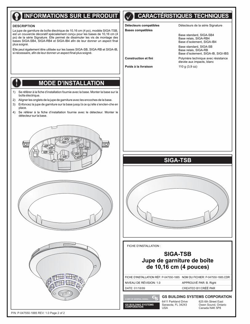
P/N: REV: 1.0 Page 2 of 2P-047550-1885
INFORMATIONS SUR LE PRODUIT
DESCRIPTIONLa jupe de garniture de boîte électrique de 10,16 cm (4 po), modèle SIGA-TSB,est un couvercle décoratif spécialement conçu pour les bases de 10,16 cm (4po) de la série Signature. Elle permet de dissimuler les vis de montage desbases SIGA-SB4, SIGA-RB4 et SIGA-IB4 afin de leur donner un aspect finalplus soigné.
Elle peut également être utilisée sur les bases SIGA-SB, SIGA-RB et SIGA-IB,si nécessaire, afin de leur donner un aspect final plus soigné.
CARACTÉRISTIQUES TECHNIQUES
Détecteurs compatibles
Bases compatibles
Construction et fini
Poids à la livraison
Détecteurs de la série Signature
Base standard, SIGA-SB4Base relais, SIGA-RB4Base d’isolement, SIGA-IB4
Base standard, SIGA-SBBase relais, SIGA-RBBase d’isolement, SIGA-IB, SIGI-IBS
Polymère technique avec résistanceélevée aux impacts, blanc
110 g (3,9 oz)
SIGA-TSBJupe de garniture de boîte
de 10,16 cm (4 pouces)
MODE D’INSTALLATION1) Se référer à la fiche d’installation fournie avec la base. Monter la base sur la
boîte électrique.
2) Aligner les onglets de la jupe de garniture avec les encoches de la base.
3) Enfoncez la jupe de garniture sur la base jusqu’à ce qu’elle s’enclen-che enplace.
4) Se référer à la fiche d’installation fournie avec le détecteur. Monter ledétecteur sur la base.
GS BUILDING SYSTEMSCORPORATION
A UNIT OF GENERAL SIGNALGS BUILDING SYSTEMS CORPORATION6411 Parkland DriveSarasota, FL 34243USA
625 6th Street EastOwen Sound, OntarioCanada N4K 5P8
DATE: 01/18/99
FICHE D’INSTALLATION :
FICHE D’INSTALLATION RÉF: P-047550-1885
NIVEAU DE RÉVISION: 1.0
NOM DU FICHIER: .CDRP-047550-1885
CREATED BY:CRÉÉ PAR
APPROUVÉ PAR: B. Right
SIGA-TSB
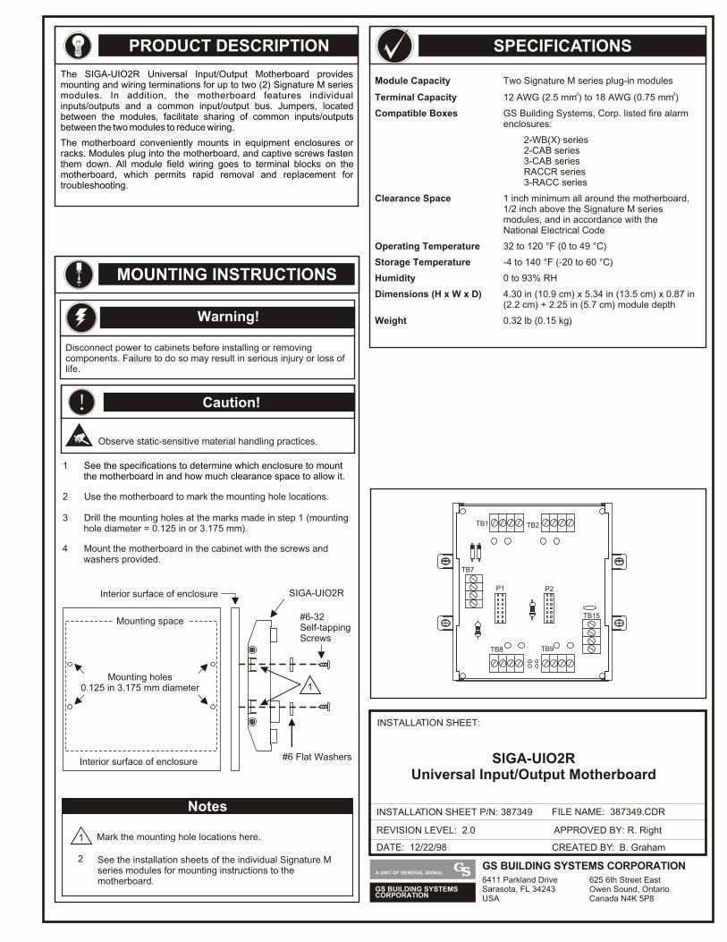
PRODUCT DESCRIPTION
The SIGA-UIO2R Universal Input/Output Motherboard provides mounting and wiring terminations for up to two (2) Signature M series modules. In addition, the motherboard features individual inputs/outputs and a common input/output bus. Jumpers, located between the modules, facilitate sharing of common inputs/outputs between the two modules to reduce wiring.
The motherboard conveniently mounts in equipment enclosures or racks. Modules plug into the motherboard, and captive screws fasten them down. All module field wiring goes to terminal blocks on the motherboard, which permits rapid removal and replacement for troubleshooting.
SPECIFICATIONS
Module Capacity Two Signature M series plug-in modules2 2Terminal Capacity 12 AWG (2.5 mm ) to 18 AWG (0.75 mm )
Compatible Boxes GS Building Systems, Corp. listed fire alarm enclosures:
2-WB(X) series2-CAB3-CABRACCR
Clearance Space 1 inch minimum all around the motherboard, 1/2 inch above the Signature M series modules, and in accordance with the National Electrical Code
Operating Temperature 32 to 120 °F (0 to 49 °C)
Storage Temperature -4
Humidity 0 to 93% RH
Dimensions (H x W x D) 4.30 in (10.9 cm) x 5.34 in (13.5 cm) x 0.87 in (2.2 cm) + 2.25 in (5.7 cm) module depth
Weight 0.32 lb (0.15 kg)
series series
series3-RACC series
to 140 °F (-20 to 60 °C)
MOUNTING INSTRUCTIONS
Warning!
Disconnect power to cabinets before installing or removing components. Failure to do so may result in serious injury or loss of life.
3 Drill the mounting holes at the marks made in step 1 (mounting hole diameter = 0.125 in or 3.175 mm).
2 Use the motherboard to mark the mounting hole locations.
1 See the specifications to determine which enclosure to mount the motherboard in and how much clearance space to allow it.
4 Mount the motherboard in the cabinet with the screws and washers provided.
#6 Flat Washers
#6-32Self-tapping Screws
SIGA-UIO2R
Mounting space
P1 P2
TB1 TB2
TB7
TB8 TB9
TB15
DATE: 12/22/98
INSTALLATION SHEET:
INSTALLATION SHEET P/N: 387349 FILE NAME: 387349.CDR
REVISION LEVEL: 2.0
CREATED BY: B. Graham
APPROVED BY: R. Right
SIGA-UIO2RUniversal Input/Output Motherboard
See the installation sheets of the individual Signature M series modules for mounting instructions to the motherboard.
GS BUILDING SYSTEMSCORPORATION
A UNIT OF GENERAL SIGNALGS BUILDING SYSTEMS CORPORATION6411 Parkland DriveSarasota, FL 34243USA
625 6th Street EastOwen Sound, OntarioCanada N4K 5P8
! Caution!
Observe static-sensitive material handling practices.
Mounting holes0.125 in 3.175 mm diameter
Interior surface of enclosure
Interior surface of enclosure
Mark the mounting hole locations here.
2
1
Notes
1
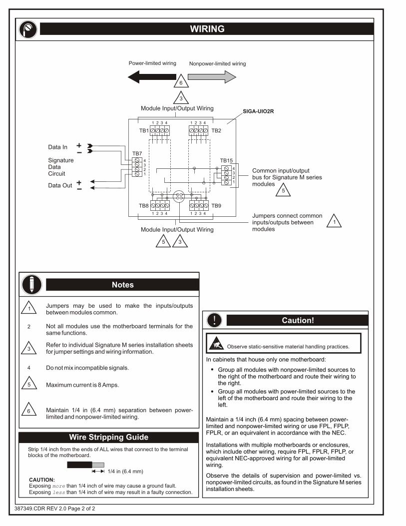
Wire Stripping Guide
1/4 in (6.4 mm)
Strip 1/4 inch from the ends of ALL wires that connect to the terminalblocks of the motherboard.
CAUTION:Exposing more than 1/4 inch of wire may cause a ground fault.Exposing less than 1/4 inch of wire may result in a faulty connection.
WIRING
387349.CDR REV 2.0 Page 2 of 2
Notes
Jumpers may be used to make the inputs/outputs between modules common.
Not all modules use the motherboard terminals for the same functions.
Refer to individual Signature M series installation sheets for jumper settings and wiring information.
Do not mix incompatible signals.
Maximum current is 8 Amps.
Maintain 1/4 in (6.4 mm) separation between power-limited and nonpower-limited wiring.
1
2
3
4
5
6
6
Observe the details of supervision and power-limited vs. nonpower-limited circuits, as found in the Signature M series installation sheets.
Maintain a 1/4 inch (6.4 mm) spacing between power-limited and nonpower-limited wiring or use FPL, FPLP, FPLR, or an equirvalent in accordance with the NEC.
Installations with multiple motherboards or enclosures, which include other wiring, require FPL, FPLR, FPLP, or equivalent NEC-approved wiring for all power-limited wiring.
! Caution!
Observe static-sensitive material handling practices.
4321
1 2 3 4
1 2 3 4
1 2 3 4
1 2 3 4
4321
TB15
TB1
TB8
TB7
TB2
TB9
SignatureDataCircuit
Data Out
Data In
SIGA-UIO2R
Common input/output bus for Signature M seriesmodules
Jumpers connect commoninputs/outputs betweenmodulesModule Input/Output Wiring
1
3
35
5
Module Input/Output Wiring
Power-limited wiring Nonpower-limited wiring
In cabinets that house only one motherboard:
Group all modules with nonpower-limited sources to the right of the motherboard and route their wiring to the right.
Group all modules with power-limited sources to the left of the motherboard and route their wiring to the left.
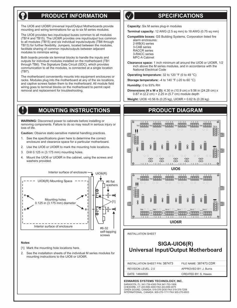
DATE: 14MAR00
INSTALLATION SHEET
INSTALLATION SHEET P/N: 387473
REVISION LEVEL: 2.0
FILE NAME: 387473.CDR
CREATED BY: S. Hawes
APPROVED BY: J. Burns
PRODUCT INFORMATION
MOUNTING INSTRUCTIONS PRODUCT DIAGRAM
SPECIFICATIONS
Capacity:
Terminal capacity:
Compatible boxes:
Clearance space:
Operating temperature:
Storage temperature:
Humidity:
Dimensions (H x W x D):
Weight:
Six M series plug-in modules
12 (2.5 sq mm) to 18 (0.75 sq mm)
GS Building Systems, Corporation listed firealarm enclosures:2-WB(X) series3-CAB seriesRACCR series3-RACC seriesMFC-A Cabinet
1 inch minimum all around the UIO6 or UIO6R, 1/2inch above the M series modules, and in accordance with theNational Electrical Code
32 to 120 °F (0 to 49 °C)
-4 to 140 °F (-20 to 60 °C)
0 to 93% RH
4.30 in (10.9 cm) x 9.56 in (24.28 cm) x0.87 in (2.2 cm) + 2.25 in (5.7 cm) module depth
UIO6 =0.56 lb (0.25 kg), UIO6R = 0.62 lb (0.28 kg)
AWG AWG
The UIO6 and UIO6R Universal Input/Output Motherboards providemounting and wiring terminations for up to six M series modules.
The UIO6 provides two input/output buses common to all modules(TB14 and TB15). The UIO6R provides one input/output bus commonto all modules (TB15) and six individual inputs/outputs (TB8 throughTB13) for further flexibility. Jumpers, located between the modules,facilitate sharing of common inputs/outputs between adjacentmodules to minimize wiring.
Both boards provide six terminal blocks to handle the inputs andoutputs for individual modules installed on the motherboard (TB1through TB6). The Signature Data Circuit (SDC), which providescommunication to all the modules, is connected at a single location(TB7).
The motherboard conveniently mounts into equipment enclosures orracks. Modules plug into the motherboard at any of the six locations,and captive screws fasten them to the motherboard. All module fieldwiring goes to terminal blocks on the motherboard to permit rapidremoval and replacement for troubleshooting.
#6 flatwashers
#6-32self-tappingscrews
Interior surface of enclosure
Interior surface of enclosure
UIO6(R)
Mounting holes0.125 in (3.175 mm) diameter
UIO6(R) Mounting Space
Notes
[1] Mark the mounting hole locations here.
2. See the installation sheets of the individual M series modules formounting instructions to the UIO6 or UIO6R.
WARNING: Disconnect power to cabinets before installing orremoving components. Failure to do so may result in serious injury orloss of life.
1. See the specifications given here to determine the correctenclosure and clearance space for a particular motherboard.
2. Use the UIO6 or UIO6R to mark the mounting hole locations.
3. Drill mounting holes.
4. Mount the UIO6 or UIO6R in the cabinet, using the screws andwashers provided.
Caution: Observe static-sensitive material handling practices.
0.125 in (3.175 mm)
[1]
TB7
4321
1 2 3 4
1 2 3 4
1 2 3 4
1 2 3 4
P1 P2
TB1
TB8JP1A JP2A JP3A JP4A JP5A
JP1B JP2B JP3B JP4B JP5B
TB9 TB10 TB11 TB12 TB13
TB2
1 2 3 4
1 2 3 4
1 2 3 4
1 2 3 4
P3 P4
TB3 TB4
1 2 3 4
1 2 3 4
1 2 3 4
1 2 3 4
P5 P6
TB5 TB6
TB15
4321
4321
4321
1 2 3 4
1 2 3 4
1 2 3 4
1 2 3 4
P1 P2
TB1 TB2
1 2 3 4
1 2 3 4
1 2 3 4
1 2 3 4
P3 P4
TB3 TB4
1 2 3 4
1 2 3 4
1 2 3 4
1 2 3 4
P5 P6
TB5 TB6
4321
TB7
TB14
TB15
UIO6R
UIO6
SIGA-UIO6(R)Universal Input/Output Motherboard
EDWARDS SYSTEMS TECHNOLOGY, INC.SARASOTA, FL: 941-739-4300 FAX 941-753-1806CHESHIRE, CT: 203-699-3000 FAX 203-699-3075OWEN SOUND, CANADA: 519-376-2430 FAX 519-376-7258INTERNATIONAL, CANADA: 905-270-1711 FAX 905-270-9553
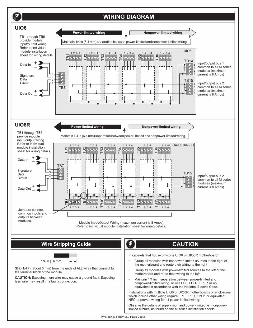
TB1 through TB6provide moduleinput/output wiring.Refer to individualmodule installationsheet for wiring details.
Module Input/Output Wiring (maximum current is 8 Amps)Refer to individual module installation sheet for wiring details.
Input/output bus 2common to all M seriesmodules (maximumcurrent is 8 Amps)
Jumpers connectcommon inputs andoutputs betweenmodules.
SIGA-UIO6R-LG
TB
8
TB
9
TB
10
TB
11
TB
12
TB
13
TB15
TB
2
TB
3
TB
4
TB
5
TB
6
1 2 3 4
1 2 3 4
1 2 3 4
1 2 3 4
1 2 3 4
1 2 3 4
1 2 3 4
1 2 3 4
1 2 3 4
1 2 3 4
1 2 3 4
1 2 3 4
4321
UIO6R
SignatureDataCircuit
Data Out
Data In
TB
1
TB7
Power-limited wiring Nonpower-limited wiring
Maintain 1/4 in (6.4 mm) separation between power-limited and nonpower-limited wiring.
4321
TB1 through TB6provide moduleinput/output wiring.Refer to individualmodule installationsheet for wiring details.
Input/output bus 1common to all M seriesmodules (maximumcurrent is 8 Amps)
Input/output bus 2common to all M seriesmodules (maximumcurrent is 8 Amps)
TB144321
1 2 3 4 1 2 3 4 1 2 3 4 1 2 3 4 1 2 3 4 1 2 3 4
4321
TB15
UIO6
TB
1
TB
2
TB
3
TB
4
TB
5
TB
6
UIO6
TB7
Power-limited wiring Nonpower-limited wiring
Maintain 1/4 in (6.4 mm) separation between power-limited and nonpower-limited wiring.
SignatureDataCircuit
Data Out
Data In
4321
CAUTION
WIRING DIAGRAM
Wire Stripping Guide
Strip 1/4 in (about 6 mm) from the ends of ALL wires that connect tothe terminal block of the module.
Exposing more wire may cause a ground fault. Exposingless wire may result in a faulty connection.CAUTION:
1/4 in (~6 mm)
P/N: REV: 2.0 Page 2 of 2387473
In cabinets that house only one UIO6 or UIO6R motherboard:
• Group all modules with nonpower-limited sources to the right ofthe motherboard and route their wiring to the right
• Group all modules with power-limited sources to the left of themotherboard and route their wiring to the left
• Maintain 1/4 inch separation between power-limited andnonpower-limited wiring, or use FPL, FPLR, FPLP, or anequivalent in accordance with the National Electric Code.
Installations with multiple UIO6 or UIO6R motherboards or enclosureswhich include other wiring require FPL, FPLR, FPLP, or equivalentNEC-approved wiring for all power-limited wiring.
Observe the details of supervision and power-limited vs. nonpower-limited circuits, as found on the M series installation sheets.
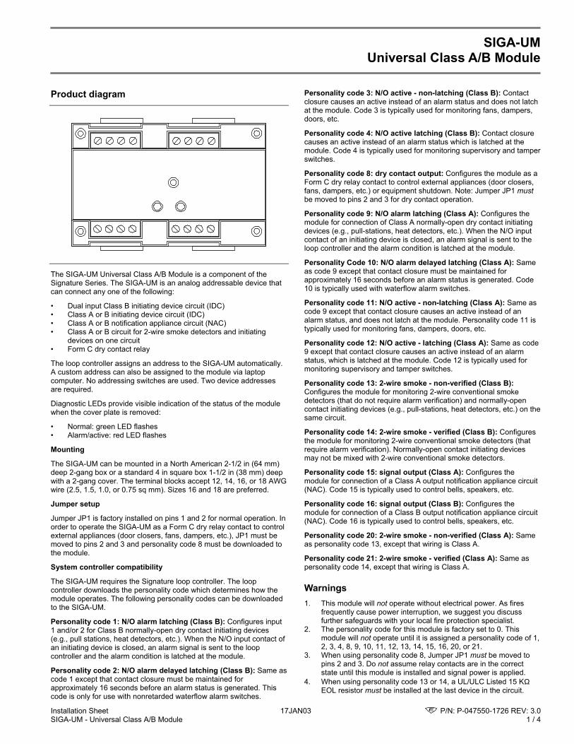
Installation Sheet 17JAN03 P/N: P-047550-1726 REV: 3.0SIGA-UM - Universal Class A/B Module 1 / 4
SIGA-UMUniversal Class A/B Module
Product diagram
The SIGA-UM Universal Class A/B Module is a component of theSignature Series. The SIGA-UM is an analog addressable device thatcan connect any one of the following:
• Dual input Class B initiating device circuit (IDC)• Class A or B initiating device circuit (IDC)• Class A or B notification appliance circuit (NAC)• Class A or B circuit for 2-wire smoke detectors and initiating
devices on one circuit• Form C dry contact relay
The loop controller assigns an address to the SIGA-UM automatically.A custom address can also be assigned to the module via laptopcomputer. No addressing switches are used. Two device addressesare required.
Diagnostic LEDs provide visible indication of the status of the modulewhen the cover plate is removed:
• Normal: green LED flashes• Alarm/active: red LED flashes
Mounting
The SIGA-UM can be mounted in a North American 2-1/2 in (64 mm)deep 2-gang box or a standard 4 in square box 1-1/2 in (38 mm) deepwith a 2-gang cover. The terminal blocks accept 12, 14, 16, or 18 AWGwire (2.5, 1.5, 1.0, or 0.75 sq mm). Sizes 16 and 18 are preferred.
Jumper setup
Jumper JP1 is factory installed on pins 1 and 2 for normal operation. Inorder to operate the SIGA-UM as a Form C dry relay contact to controlexternal appliances (door closers, fans, dampers, etc.), JP1 must bemoved to pins 2 and 3 and personality code 8 must be downloaded tothe module.
System controller compatibility
The SIGA-UM requires the Signature loop controller. The loopcontroller downloads the personality code which determines how themodule operates. The following personality codes can be downloadedto the SIGA-UM.
Personality code 1: N/O alarm latching (Class B): Configures input1 and/or 2 for Class B normally-open dry contact initiating devices(e.g., pull stations, heat detectors, etc.). When the N/O input contact ofan initiating device is closed, an alarm signal is sent to the loopcontroller and the alarm condition is latched at the module.
Personality code 2: N/O alarm delayed latching (Class B): Same ascode 1 except that contact closure must be maintained forapproximately 16 seconds before an alarm status is generated. Thiscode is only for use with nonretarded waterflow alarm switches.
Personality code 3: N/O active - non-latching (Class B): Contactclosure causes an active instead of an alarm status and does not latchat the module. Code 3 is typically used for monitoring fans, dampers,doors, etc.
Personality code 4: N/O active latching (Class B): Contact closurecauses an active instead of an alarm status which is latched at themodule. Code 4 is typically used for monitoring supervisory and tamperswitches.
Personality code 8: dry contact output: Configures the module as aForm C dry relay contact to control external appliances (door closers,fans, dampers, etc.) or equipment shutdown. Note: Jumper JP1 mustbe moved to pins 2 and 3 for dry contact operation.
Personality code 9: N/O alarm latching (Class A): Configures themodule for connection of Class A normally-open dry contact initiatingdevices (e.g., pull-stations, heat detectors, etc.). When the N/O inputcontact of an initiating device is closed, an alarm signal is sent to theloop controller and the alarm condition is latched at the module.
Personality Code 10: N/O alarm delayed latching (Class A): Sameas code 9 except that contact closure must be maintained forapproximately 16 seconds before an alarm status is generated. Code10 is typically used with waterflow alarm switches.
Personality code 11: N/O active - non-latching (Class A): Same ascode 9 except that contact closure causes an active instead of analarm status, and does not latch at the module. Personality code 11 istypically used for monitoring fans, dampers, doors, etc.
Personality code 12: N/O active - latching (Class A): Same as code9 except that contact closure causes an active instead of an alarmstatus, which is latched at the module. Code 12 is typically used formonitoring supervisory and tamper switches.
Personality code 13: 2-wire smoke - non-verified (Class B):Configures the module for monitoring 2-wire conventional smokedetectors (that do not require alarm verification) and normally-opencontact initiating devices (e.g., pull-stations, heat detectors, etc.) on thesame circuit.
Personality code 14: 2-wire smoke - verified (Class B): Configuresthe module for monitoring 2-wire conventional smoke detectors (thatrequire alarm verification). Normally-open contact initiating devicesmay not be mixed with 2-wire conventional smoke detectors.
Personality code 15: signal output (Class A): Configures themodule for connection of a Class A output notification appliance circuit(NAC). Code 15 is typically used to control bells, speakers, etc.
Personality code 16: signal output (Class B): Configures themodule for connection of a Class B output notification appliance circuit(NAC). Code 16 is typically used to control bells, speakers, etc.
Personality code 20: 2-wire smoke - non-verified (Class A): Sameas personality code 13, except that wiring is Class A.
Personality code 21: 2-wire smoke - verified (Class A): Same aspersonality code 14, except that wiring is Class A.
Warnings1. This module will not operate without electrical power. As fires
frequently cause power interruption, we suggest you discussfurther safeguards with your local fire protection specialist.
2. The personality code for this module is factory set to 0. Thismodule will not operate until it is assigned a personality code of 1,2, 3, 4, 8, 9, 10, 11, 12, 13, 14, 15, 16, 20, or 21.
3. When using personality code 8, Jumper JP1 must be moved topins 2 and 3. Do not assume relay contacts are in the correctstate until this module is installed and signal power is applied.
4. When using personality code 13 or 14, a UL/ULC Listed 15 KΩEOL resistor must be installed at the last device in the circuit.
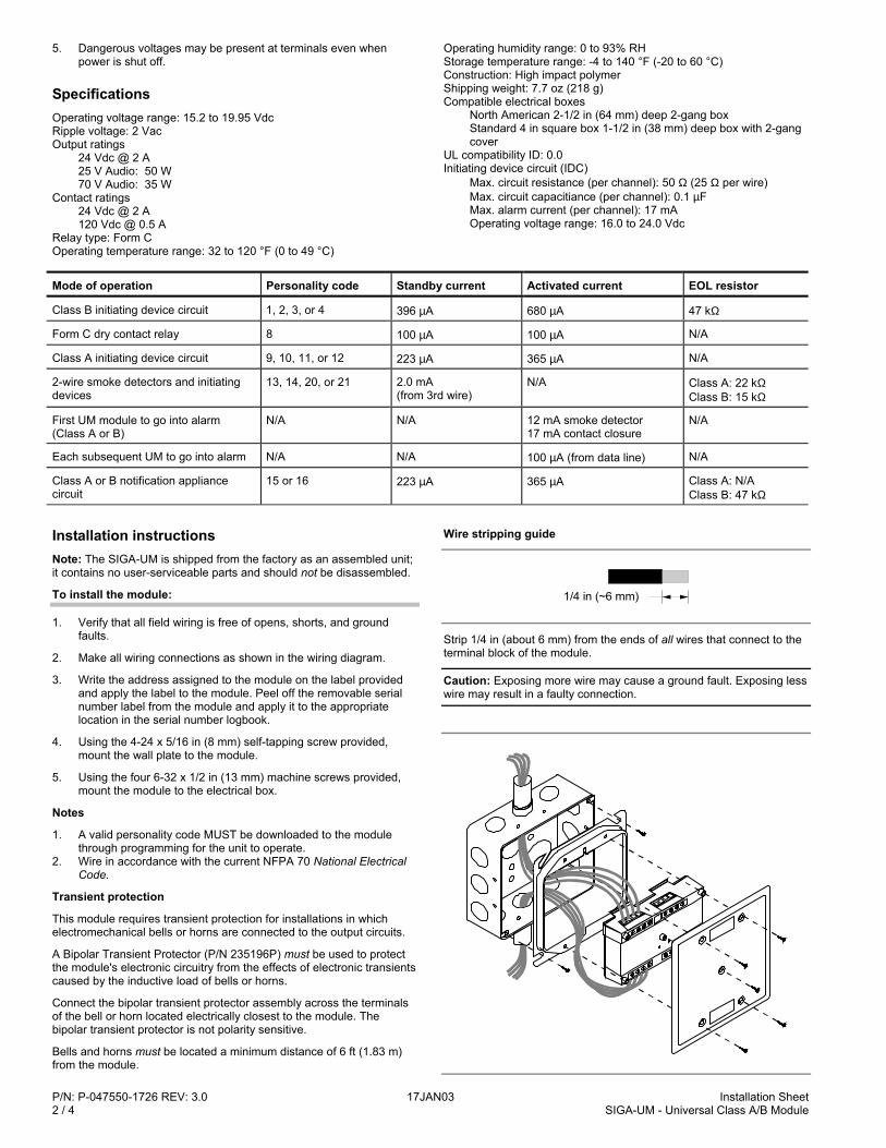
P/N: P-047550-1726 REV: 3.0 17JAN03 Installation Sheet2 / 4 SIGA-UM - Universal Class A/B Module
5. Dangerous voltages may be present at terminals even whenpower is shut off.
SpecificationsOperating voltage range: 15.2 to 19.95 VdcRipple voltage: 2 VacOutput ratings
24 Vdc @ 2 A25 V Audio: 50 W70 V Audio: 35 W
Contact ratings24 Vdc @ 2 A120 Vdc @ 0.5 A
Relay type: Form COperating temperature range: 32 to 120 °F (0 to 49 °C)
Operating humidity range: 0 to 93% RHStorage temperature range: -4 to 140 °F (-20 to 60 °C)Construction: High impact polymerShipping weight: 7.7 oz (218 g)Compatible electrical boxes
North American 2-1/2 in (64 mm) deep 2-gang boxStandard 4 in square box 1-1/2 in (38 mm) deep box with 2-gangcover
UL compatibility ID: 0.0Initiating device circuit (IDC)
Max. circuit resistance (per channel): 50 Ω (25 Ω per wire)Max. circuit capacitiance (per channel): 0.1 µFMax. alarm current (per channel): 17 mAOperating voltage range: 16.0 to 24.0 Vdc
Mode of operation Personality code Standby current Activated current EOL resistor
Class B initiating device circuit 1, 2, 3, or 4 396 µA 680 µA 47 kΩ
Form C dry contact relay 8 100 µA 100 µA N/A
Class A initiating device circuit 9, 10, 11, or 12 223 µA 365 µA N/A
2-wire smoke detectors and initiatingdevices
13, 14, 20, or 21 2.0 mA(from 3rd wire)
N/A Class A: 22 kΩClass B: 15 kΩ
First UM module to go into alarm(Class A or B)
N/A N/A 12 mA smoke detector17 mA contact closure
N/A
Each subsequent UM to go into alarm N/A N/A 100 µA (from data line) N/A
Class A or B notification appliancecircuit
15 or 16 223 µA 365 µA Class A: N/AClass B: 47 kΩ
Installation instructionsNote: The SIGA-UM is shipped from the factory as an assembled unit;it contains no user-serviceable parts and should not be disassembled.
To install the module:
1. Verify that all field wiring is free of opens, shorts, and groundfaults.
2. Make all wiring connections as shown in the wiring diagram.
3. Write the address assigned to the module on the label providedand apply the label to the module. Peel off the removable serialnumber label from the module and apply it to the appropriatelocation in the serial number logbook.
4. Using the 4-24 x 5/16 in (8 mm) self-tapping screw provided,mount the wall plate to the module.
5. Using the four 6-32 x 1/2 in (13 mm) machine screws provided,mount the module to the electrical box.
Notes
1. A valid personality code MUST be downloaded to the modulethrough programming for the unit to operate.
2. Wire in accordance with the current NFPA 70 National ElectricalCode.
Transient protection
This module requires transient protection for installations in whichelectromechanical bells or horns are connected to the output circuits.
A Bipolar Transient Protector (P/N 235196P) must be used to protectthe module's electronic circuitry from the effects of electronic transientscaused by the inductive load of bells or horns.
Connect the bipolar transient protector assembly across the terminalsof the bell or horn located electrically closest to the module. Thebipolar transient protector is not polarity sensitive.
Bells and horns must be located a minimum distance of 6 ft (1.83 m)from the module.
Wire stripping guide
1/4 in (~6 mm)
Strip 1/4 in (about 6 mm) from the ends of all wires that connect to theterminal block of the module.
Caution: Exposing more wire may cause a ground fault. Exposing lesswire may result in a faulty connection.
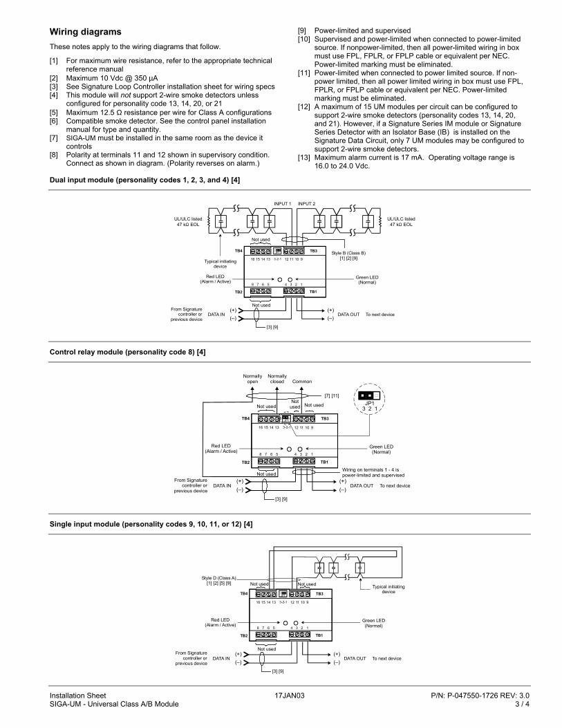
Installation Sheet 17JAN03 P/N: P-047550-1726 REV: 3.0SIGA-UM - Universal Class A/B Module 3 / 4
Wiring diagramsThese notes apply to the wiring diagrams that follow.
[1] For maximum wire resistance, refer to the appropriate technicalreference manual
[2] Maximum 10 Vdc @ 350 µA[3] See Signature Loop Controller installation sheet for wiring specs[4] This module will not support 2-wire smoke detectors unless
configured for personality code 13, 14, 20, or 21[5] Maximum 12.5 Ω resistance per wire for Class A configurations[6] Compatible smoke detector. See the control panel installation
manual for type and quantity.[7] SIGA-UM must be installed in the same room as the device it
controls[8] Polarity at terminals 11 and 12 shown in supervisory condition.
Connect as shown in diagram. (Polarity reverses on alarm.)
[9] Power-limited and supervised[10] Supervised and power-limited when connected to power-limited
source. If nonpower-limited, then all power-limited wiring in boxmust use FPL, FPLR, or FPLP cable or equivalent per NEC.Power-limited marking must be eliminated.
[11] Power-limited when connected to power limited source. If non-power limited, then all power limited wiring in box must use FPL,FPLR, or FPLP cable or equivalent per NEC. Power-limitedmarking must be eliminated.
[12] A maximum of 15 UM modules per circuit can be configured tosupport 2-wire smoke detectors (personality codes 13, 14, 20,and 21). However, if a Signature Series IM module or SignatureSeries Detector with an Isolator Base (IB) is installed on theSignature Data Circuit, only 7 UM modules may be configured tosupport 2-wire smoke detectors.
[13] Maximum alarm current is 17 mA. Operating voltage range is16.0 to 24.0 Vdc.
Dual input module (personality codes 1, 2, 3, and 4) [4]
Style B (Class B)[1] [2] [9]
[3] [9]
Not used
TB4
TB2
Red LED(Alarm / Active)
Green LED(Normal)
Not usedFrom Signature
controller or previous device
DATA IN(+)(–)
(+)(–)
Typical initiating device
UL/ULC listed47 k EOLΩ
INPUT 1 INPUT 2
UL/ULC listed47 k EOLΩ
DATA OUT To next device
TB3
TB1
4 3 2 18 7 6 5
16 15 14 13 12 11 10 93-2-1
JP1
Control relay module (personality code 8) [4]
[3] [9]
Not used
TB4
TB2
Red LED(Alarm / Active)
Green LED(Normal)
Not usedFrom Signature
controller or previous device
DATA IN(+)(–)
(+)(–)
DATA OUT To next device
TB3
TB1
4 3 2 18 7 6 5
16 15 14 13 12 11 10 93-2-1
JP1
Wiring on terminals 1 - 4 is power-limited and supervised
Notused Not used
Normallyopen
Normallyclosed Common
[7] [11]JP1
3 2 1
Single input module (personality codes 9, 10, 11, or 12) [4]
[3] [9]
TB4
TB2
Red LED(Alarm / Active)
Green LED(Normal)
Not usedFrom Signature
controller or previous device
DATA IN(+)(–)
(+)(–)
DATA OUT To next device
TB3
TB1
4 3 2 18 7 6 5
16 15 14 13 12 11 10 93-2-1
JP1
Typical initiating device
Style D (Class A)[1] [2] [5] [9] Not used Not used
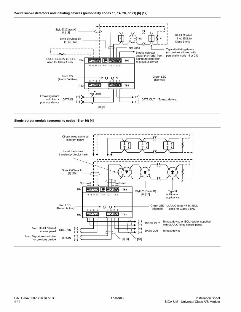
P/N: P-047550-1726 REV: 3.0 17JAN03 Installation Sheet4 / 4 SIGA-UM - Universal Class A/B Module
2-wire smoke detectors and initiating devices (personality codes 13, 14, 20, or 21) [6] [12]
[3] [9]
TB4
TB2
Red LED(Alarm / Active)
Green LED(Normal)
Not usedFrom Signature
controller or previous device
DATA IN(+)(–)
(+)(–)
DATA OUT To next device
TB3
TB1
4 3 2 18 7 6 5
16 15 14 13 12 11 10 93-2-1
JP1
Style D (Class A)[5] [13]
Style B (Class B)[1] [9] [13]
UL/ULC listed 22 k EOL used for Class A only
Ω
IN+
OUT+
[6]UL/ULC listed 15 k EOL for Class B only
Ω
Not used
Smoke detector power (+24 Vdc) from Signature controller or previous device
Typical initiating device (no devices allowed with personality code 14 or 21)
Single output module (personality codes 15 or 16) [4]
TB4
TB2
Red LED(Alarm / Active)
Green LED(Normal)
TB3
TB1
4 3 2 18 7 6 5
16 15 14 13 12 11 10 93-2-1
JP1
[3] [9]
To next deviceFrom UL/ULC listed
control panel RISER IN (+)(–) DATA OUT
(+)(–)
DATA IN(+)(–)
From Signature controller or previous device
Style Z (Class A)[1] [10]
Style Y (Class B)[8] [10]
Install the bipolar transient protector here
Circuit wired same as diagram below
Not used Not used
UL/ULC listed 47 k EOLused for Class B only
Ω
Typical notification applicance
To next device or EOL resistor supplied with UL/ULC listed control panelRISER OUT
(+)(–)
[10]
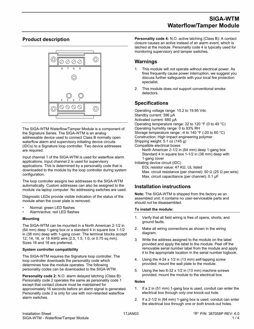
Installation Sheet 17JAN03 P/N: 387058P REV: 6.0SIGA-WTM - Waterflow/Tamper Module 1 / 4
SIGA-WTMWaterflow/Tamper Module
Product description
1234
5678
The SIGA-WTM Waterflow/Tamper Module is a component ofthe Signature Series. The SIGA-WTM is an analogaddressable device used to connect Class B normally openwaterflow alarm and supervisory initiating device circuits(IDCs) to a Signature loop controller. Two device addressesare required.
Input channel 1 of the SIGA-WTM is used for waterflow alarmapplications. Input channel 2 is used for supervisoryapplications. This is determined by a personality code that isdownloaded to the module by the loop controller during systemconfiguration.
The loop controller assigns two addresses to the SIGA-WTMautomatically. Custom addresses can also be assigned to themodule via laptop computer. No addressing switches are used.
Diagnostic LEDs provide visible indication of the status of themodule when the cover plate is removed:
• Normal: green LED flashes• Alarm/active: red LED flashes
Mounting
The SIGA-WTM can be mounted in a North American 2-1/2 in(64 mm) deep 1-gang box or a standard 4 in square box 1-1/2in (38 mm) deep with 1-gang cover. The terminal blocks accept12, 14, 16, or 18 AWG wire (2.5, 1.5, 1.0, or 0.75 sq mm).Sizes 16 and 18 are preferred.
System controller compatibility
The SIGA-WTM requires the Signature loop controller. Theloop controller downloads the personality code whichdetermines how the module operates. The followingpersonality codes can be downloaded to the SIGA-WTM.
Personality code 2: N.O. alarm delayed latching (Class B):Personality code 2 operates the same as personality code 1except that contact closure must be maintained forapproximately 16 seconds before an alarm signal is generated.Personality code 2 is only for use with non-retarded waterflowalarm switches.
Personality code 4: N.O. active latching (Class B): A contactclosure causes an active instead of an alarm event, which islatched at the module. Personality code 4 is typically used formonitoring supervisory and tamper switches.
Warnings1. This module will not operate without electrical power. As
fires frequently cause power interruption, we suggest youdiscuss further safeguards with your local fire protectionspecialist.
2. This module does not support conventional smokedetectors.
SpecificationsOperating voltage range: 15.2 to 19.95 VdcStandby current: 396 µAActivated current: 680 µAOperating temperature range: 32 to 120 °F (0 to 49 °C)Operating humidity range: 0 to 93% RHStorage temperature range: -4 to 140 °F (-20 to 60 °C)Construction: High impact engineering polymerShipping weight: 5.1 oz (145 g)Compatible electrical boxes
North American 2-1/2 in (64 mm) deep 1-gang boxStandard 4 in square box 1-1/2 in (38 mm) deep with1-gang cover
Initiating device circuit (IDC)EOL resistor value: 47 KΩ, UL listedMax. circuit resistance (per channel): 50 Ω (25 Ω per wire)Max. circuit capacitiance (per channel): 0.1 µF
Installation instructionsNote: The SIGA-WTM is shipped from the factory as anassembled unit; it contains no user-serviceable parts andshould not be disassembled.
To install the module:
1. Verify that all field wiring is free of opens, shorts, andground faults.
2. Make all wiring connections as shown in the wiringdiagram.
3. Write the address assigned to the module on the labelprovided and apply the label to the module. Peel off theremovable serial number label from the module and applyit to the appropriate location in the serial number logbook.
4. Using the 4-24 x 1/2 in (13 mm) self-tapping screwprovided, mount the wall plate to the module.
5. Using the two 6-32 x 1/2 in (13 mm) machine screwsprovided, mount the module to the electrical box.
Notes
1. If a 2 in (51 mm) 1-gang box is used, conduit can enter theelectrical box through only one knock-out hole.
2. If a 2-1/2 in (64 mm) 1-gang box is used, conduit can enterthe electrical box through one or both knock-out holes.
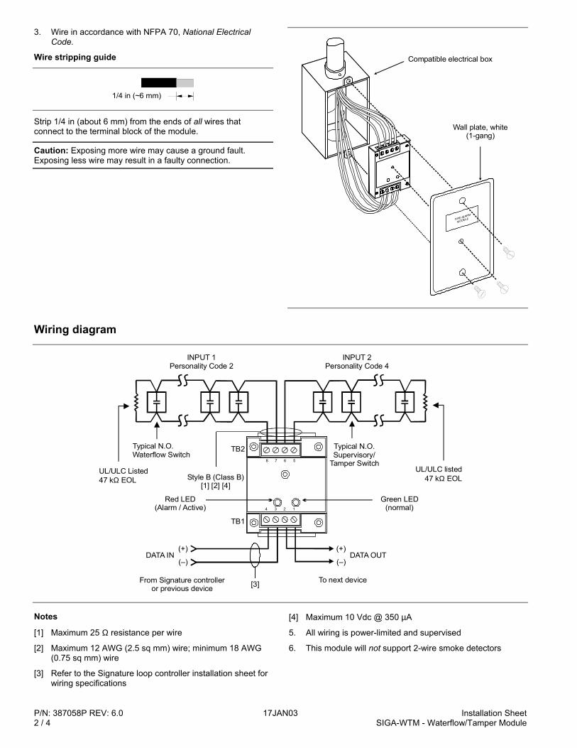
P/N: 387058P REV: 6.0 17JAN03 Installation Sheet2 / 4 SIGA-WTM - Waterflow/Tamper Module
3. Wire in accordance with NFPA 70, National ElectricalCode.
Wire stripping guide
1/4 in (~6 mm)
Strip 1/4 in (about 6 mm) from the ends of all wires thatconnect to the terminal block of the module.
Caution: Exposing more wire may cause a ground fault.Exposing less wire may result in a faulty connection.
Compatible electrical box
Wall plate, white(1-gang)
Wiring diagram
(+)
(–)DATA OUT
INPUT 1Personality Code 2
INPUT 2Personality Code 4
UL/ULC Listed47 k EOLΩ
Typical N.O. Waterflow Switch
Style B (Class B)[1] [2] [4]
Red LED(Alarm / Active)
TB2
TB1
Typical N.O.Supervisory/
Tamper SwitchUL/ULC listed
47 k EOLΩ
Green LED(normal)
(+)
(–)
From Signature controlleror previous device [3] To next device
DATA IN
1234
5678
Notes
[1] Maximum 25 Ω resistance per wire
[2] Maximum 12 AWG (2.5 sq mm) wire; minimum 18 AWG(0.75 sq mm) wire
[3] Refer to the Signature loop controller installation sheet forwiring specifications
[4] Maximum 10 Vdc @ 350 µA
5. All wiring is power-limited and supervised
6. This module will not support 2-wire smoke detectors
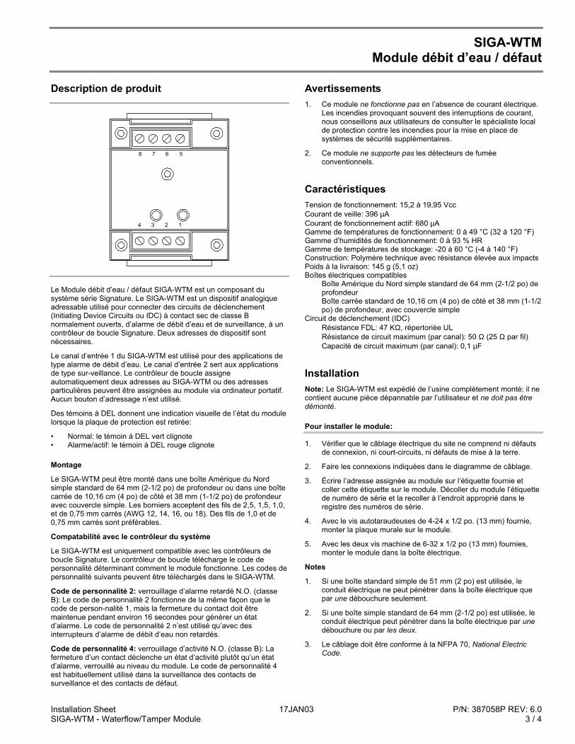
Installation Sheet 17JAN03 P/N: 387058P REV: 6.0SIGA-WTM - Waterflow/Tamper Module 3 / 4
SIGA-WTMModule débit d’eau / défaut
Description de produit
1234
5678
Le Module débit d’eau / défaut SIGA-WTM est un composant dusystème série Signature. Le SIGA-WTM est un dispositif analogiqueadressable utilisé pour connecter des circuits de déclenchement(Initiating Device Circuits ou IDC) à contact sec de classe Bnormalement ouverts, d’alarme de débit d’eau et de surveillance, à uncontrôleur de boucle Signature. Deux adresses de dispositif sontnécessaires.
Le canal d’entrée 1 du SIGA-WTM est utilisé pour des applications detype alarme de débit d’eau. Le canal d’entrée 2 sert aux applicationsde type sur-veillance. Le contrôleur de boucle assigneautomatiquement deux adresses au SIGA-WTM ou des adressesparticulières peuvent être assignées au module via ordinateur portatif.Aucun bouton d’adressage n’est utilisé.
Des témoins à DEL donnent une indication visuelle de l’état du modulelorsque la plaque de protection est retirée:
• Normal: le témoin à DEL vert clignote• Alarme/actif: le témoin à DEL rouge clignote
Montage
Le SIGA-WTM peut être monté dans une boîte Amérique du Nordsimple standard de 64 mm (2-1/2 po) de profondeur ou dans une boîtecarrée de 10,16 cm (4 po) de côté et 38 mm (1-1/2 po) de profondeuravec couvercle simple. Les borniers acceptent des fils de 2,5, 1,5, 1,0,et de 0,75 mm carrés (AWG 12, 14, 16, ou 18). Des fils de 1,0 et de0,75 mm carrés sont préférables.
Compatabilité avec le contrôleur du système
Le SIGA-WTM est uniquement compatible avec les contrôleurs deboucle Signature. Le contrôleur de boucle télécharge le code depersonnalité déterminant comment le module fonctionne. Les codes depersonnalité suivants peuvent être téléchargés dans le SIGA-WTM.
Code de personnalité 2: verrouillage d’alarme retardé N.O. (classeB): Le code de personnalité 2 fonctionne de la même façon que lecode de person-nalité 1, mais la fermeture du contact doit êtremaintenue pendant environ 16 secondes pour générer un étatd’alarme. Le code de personnalité 2 n’est utilisé qu’avec desinterrupteurs d’alarme de débit d’eau non retardés.
Code de personnalité 4: verrouillage d’activité N.O. (classe B): Lafermeture d’un contact déclenche un état d’activité plutôt qu’un étatd’alarme, verrouillé au niveau du module. Le code de personnalité 4est habituellement utilisé dans la surveillance des contacts desurveillance et des contacts de défaut.
Avertissements1. Ce module ne fonctionne pas en l’absence de courant électrique.
Les incendies provoquant souvent des interruptions de courant,nous conseillons aux utilisateurs de consulter le spécialiste localde protection contre les incendies pour la mise en place desystèmes de sécurité supplémentaires.
2. Ce module ne supporte pas les détecteurs de fuméeconventionnels.
CaractéristiquesTension de fonctionnement: 15,2 à 19,95 VccCourant de veille: 396 µACourant de fonctionnement actif: 680 µAGamme de températures de fonctionnement: 0 à 49 °C (32 à 120 °F)Gamme d’humidités de fonctionnement: 0 à 93 % HRGamme de températures de stockage: -20 à 60 °C (-4 à 140 °F)Construction: Polymère technique avec résistance élevée aux impactsPoids à la livraison: 145 g (5,1 oz)Boîtes électriques compatibles
Boîte Amérique du Nord simple standard de 64 mm (2-1/2 po) deprofondeurBoîte carrée standard de 10,16 cm (4 po) de côté et 38 mm (1-1/2po) de profondeur, avec couvercle simple
Circuit de déclenchement (IDC)Résistance FDL: 47 KΩ, répertoriée ULRésistance de circuit maximum (par canal): 50 Ω (25 Ω par fil)Capacité de circuit maximum (par canal): 0,1 µF
InstallationNote: Le SIGA-WTM est expédié de l’usine complètement monté; il necontient aucune pièce dépannable par l’utilisateur et ne doit pas êtredémonté.
Pour installer le module:
1. Vérifier que le câblage électrique du site ne comprend ni défautsde connexion, ni court-circuits, ni défauts de mise à la terre.
2. Faire les connexions indiquées dans le diagramme de câblage.
3. Écrire l’adresse assignée au module sur l’étiquette fournie etcoller cette étiquette sur le module. Décoller du module l’étiquettede numéro de série et la recoller à l’endroit approprié dans leregistre des numéros de série.
4. Avec le vis autotaraudeuses de 4-24 x 1/2 po. (13 mm) fournie,monter la plaque murale sur le module.
5. Avec les deux vis machine de 6-32 x 1/2 po (13 mm) fournies,monter le module dans la boîte électrique.
Notes
1. Si une boîte standard simple de 51 mm (2 po) est utilisée, leconduit électrique ne peut pénétrer dans la boîte électrique quepar une débouchure seulement.
2. Si une boîte simple standard de 64 mm (2-1/2 po) est utilisée, leconduit électrique peut pénétrer dans la boîte électrique par unedébouchure ou par les deux.
3. Le câblage doit être conforme à la NFPA 70, National ElectricCode.
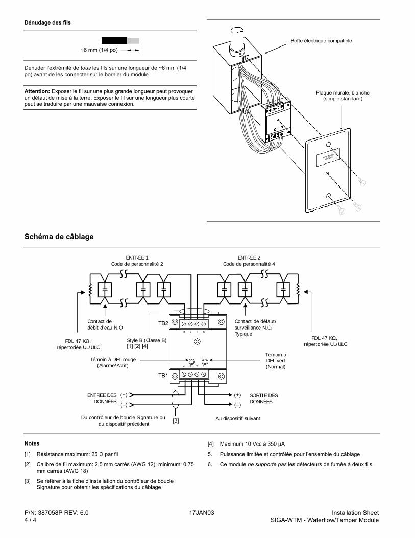
P/N: 387058P REV: 6.0 17JAN03 Installation Sheet4 / 4 SIGA-WTM - Waterflow/Tamper Module
Dénudage des fils
~6 mm 1/4 po ( )
Dénuder l’extrémité de tous les fils sur une longueur de ~6 mm (1/4po) avant de les connecter sur le bornier du module.
Attention: Exposer le fil sur une plus grande longueur peut provoquerun défaut de mise à la terre. Exposer le fil sur une longueur plus courtepeut se traduire par une mauvaise connexion.
Plaque murale, blanche (simple standard)
Boîte électrique compatible
Schéma de câblage
(+)
(–)
SORTIE DES DONNÉES
ENTRÉE 1Code de personnalité 2
ENTRÉE 2Code de personnalité 4
FDL 47 K , répertoriée UL/ULC
Ω
Contact de débit d’eau N.O
Style B (Classe B)[1] [2] [4]
Témoin à DEL rouge (Alarme/Actif)
TB2
TB1
Contact de défaut/ surveillance N.O. Typique
FDL 47 K , répertoriée UL/ULC
Ω
Témoin àDEL vert(Normal)
(+)
(–)
Du contrôleur de boucle Signature ou du dispositif précédent [3] Au dispositif suivant
ENTRÉE DES DONNÉES
1234
5678
Notes
[1] Résistance maximum: 25 Ω par fil
[2] Calibre de fil maximum: 2,5 mm carrés (AWG 12); minimum: 0,75mm carrés (AWG 18)
[3] Se référer à la fiche d’installation du contrôleur de boucleSignature pour obtenir les spécifications du câblage
[4] Maximum 10 Vcc à 350 µA
5. Puissance limitée et contrôlée pour l’ensemble du câblage
6. Ce module ne supporte pas les détecteurs de fumée à deux fils
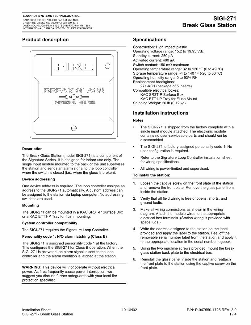
Installation Sheet 10JUN02 P/N: P-047550-1725 REV: 3.0SIGI-271 - Break Glass Station 1 / 4
EDWARDS SYSTEMS TECHNOLOGY, INC.SARASOTA, FL: 941-739-4300 FAX 941-753-1806CHESHIRE, CT: 203-699-3000 FAX 203-699-3075OWEN SOUND, CANADA: 519-376-2430 FAX 519-376-7258INTERNATIONAL, CANADA: 905-270-1711 FAX 905-270-9553
SIGI-271Break Glass Station
Product description
Description
The Break Glass Station (model SIGI-271) is a component ofthe Signature Series. It is designed for indoor use only. Thesingle input module mounted to the back of the unit supervisesthe station and sends an alarm signal to the loop controllerwhen the switch is closed (i.e., when the glass is broken).
Device addressing
One device address is required. The loop controller assigns anaddress to the SIGI-271 automatically. A custom address canbe assigned to the station via laptop computer. No addressingswitches are used.
Mounting
The SIGI-271 can be mounted in a KAC SR3T-P Surface Boxor a KAC ETT1-P Tray for flush mounting.
System controller compatibility
The SIGI-271 requires the Signature Loop Controller.
Personality code 1: N/O alarm latching (Class B)
The SIGI-271 is assigned personality code 1 at the factory.This configures the SIGI-271 for Class B operation. When theSIGI-271 is activated, an alarm signal is sent to the loopcontroller and the alarm condition is latched at the station.
WARNING: This device will not operate without electricalpower. As fires frequently cause power interruption, wesuggest you discuss further safeguards with your local fireprotection specialist.
SpecificationsConstruction: High impact plasticOperating voltage range: 15.2 to 19.95 VdcStandby current: 250 µAActivated current: 400 µASwitch contact: 150 mΩ maximumOperating temperature range: 32 to 120 °F (0 to 49 °C)Storage temperature range: -4 to 140 °F (-20 to 60 °C)Operating humidity range: 0 to 93% RHReplacement breakglass:
271-KG1 (package of 5 inserts)Compatible electrical boxes:
KAC SR3T-P Surface BoxKAC ETT1-P Tray for Flush Mount
Shipping Weight: 26 lb (0.12 kg)
Installation instructionsNotes
• The SIGI-271 is shipped from the factory complete with asingle input module attached. The electronic modulecontains no user-serviceable parts and should not bedisassembled.
• The SIGI-271 is factory assigned personality code 1. Nouser configuration is required.
• Refer to the Signature Loop Controller installation sheetfor wiring specifications.
• All wiring is power-limited and supervised.
To install the station:
1. Loosen the captive screw on the front plate of the stationand remove the front plate. Remove the glass panel frominside the station.
2. Verify that all field wiring is free of opens, shorts, andground faults.
3. Make all wiring connections as shown in the wiringdiagram. Attach the module wires to the appropriateelectrical box terminals. (Station wiring is provided withspade lugs.)
4. Write the address assigned to the station on the labelprovided and apply the label to the station. Peel off theremovable serial number label from the station and apply itto the appropriate location in the serial number logbook.
5. Using the two machine screws provided, mount the breakglass station back plate to the electrical box.
6. Reinstall the glass panel inside the station and reattachthe front plate to the station using the captive screw on thefront plate.
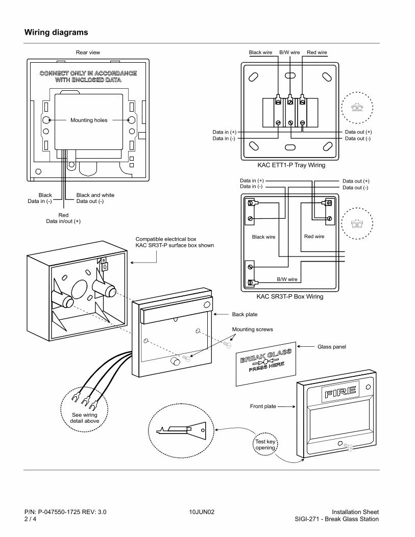
P/N: P-047550-1725 REV: 3.0 10JUN02 Installation Sheet2 / 4 SIGI-271 - Break Glass Station
Wiring diagrams
RedData in/out (+)
BlackData in (-)
Black and whiteData out (-)
Mounting holes
Rear view
Data in (+)Data in (-)
Data in (+)Data in (-)
Black wire
Black wire
KAC ETT1-P Tray Wiring
KAC SR3T-P Box Wiring
B/W wire
B/W wire Red wire
Red wire
Data out (+)
Data out (+)
Data out (-)
Data out (-)
See wiringdetail above
Compatible electrical boxKAC SR3T-P surface box shown
Glass panel
Mounting screws
Front plate
Test key opening
Back plate
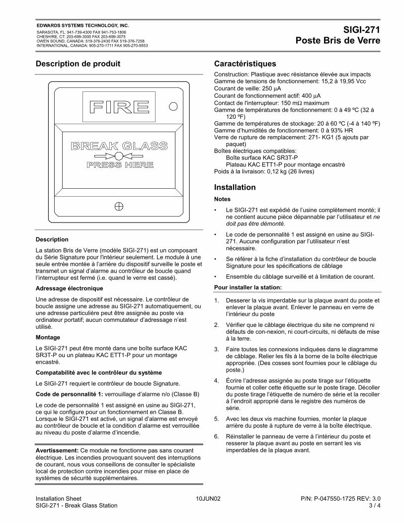
Installation Sheet 10JUN02 P/N: P-047550-1725 REV: 3.0SIGI-271 - Break Glass Station 3 / 4
EDWARDS SYSTEMS TECHNOLOGY, INC.SARASOTA, FL: 941-739-4300 FAX 941-753-1806CHESHIRE, CT: 203-699-3000 FAX 203-699-3075OWEN SOUND, CANADA: 519-376-2430 FAX 519-376-7258INTERNATIONAL, CANADA: 905-270-1711 FAX 905-270-9553
SIGI-271Poste Bris de Verre
Description de produit
Description
La station Bris de Verre (modèle SIGI-271) est un composantdu Série Signature pour l'intérieur seulement. Le module à uneseule entrée montée à l’arrière du dispositif surveille le poste ettransmet un signal d’alarme au contrôleur de boucle quandl’interrupteur est fermé (i.e. quand le verre est cassé).
Adressage électronique
Une adresse de dispositif est nécessaire. Le contrôleur deboucle assigne une adresse au SIGI-271 automatiquement, ouune adresse particulière peut être assignée au poste viaordinateur portatif; aucun commutateur d’adressage n’estutilisé.
Montage
Le SIGI-271 peut être monté dans une boîte surface KACSR3T-P ou un plateau KAC ETT1-P pour un montageencastré.
Compatabilité avec le contrôleur du système
Le SIGI-271 requiert le contrôleur de boucle Signature.
Code de personnalité 1: verrouillage d’alarme n/o (Classe B)
Le code de personnalité 1 est assigné en usine au SIGI-271,ce qui le configure pour un fonctionnement en Classe B.Lorsque le SIGI-271 est activé, un signal d’alarme est envoyéau contrôleur de boucle et la condition d’alarme est verrouilléeau niveau du poste d’alarme d’incendie.
Avertissement: Ce module ne fonctionne pas sans courantélectrique. Les incendies provoquant souvent des interruptionsde courant, nous vous conseillons de consulter le spécialistelocal de protection contre incendies pour mise en place desystèmes de sécurité supplémentaires.
CaractéristiquesConstruction: Plastique avec résistance élevée aux impactsGamme de tensions de fonctionnement: 15,2 à 19,95 VccCourant de veille: 250 µACourant de fonctionnement actif: 400 µAContact de l'interrupteur: 150 mΩ maximumGamme de températures de fonctionnement: 0 à 49 ºC (32 à
120 ºF)Gamme de températures de stockage: 20 à 60 ºC (-4 à 140 ºF)Gamme d’humidités de fonctionnement: 0 à 93% HRVerre de rupture de remplacement: 271- KG1 (5 ajouts par
paquet)Boîtes électriques compatibles:
Boîte surface KAC SR3T-PPlateau KAC ETT1-P pour montage encastré
Poids à la livraison: 0,12 kg (26 livres)
InstallationNotes
• Le SIGI-271 est expédié de l’usine complètement monté; ilne contient aucune pièce dépannable par l’utilisateur et nedoit pas être démonté.
• Le code de personnalité 1 est assigné en usine au SIGI-271. Aucune configuration par l’utilisateur n’estnécessaire.
• Se référer à la fiche d’installation du contrôleur de boucleSignature pour les spécifications de câblage
• Ensemble du câblage surveillé et à limitation de courant.
Pour installer la station:
1. Desserer la vis imperdable sur la plaque avant du poste etenlever la plaque avant. Enlever le panneau en verre del’intérieur du poste
2. Vérifier que le câblage électrique du site ne comprend nidéfauts de con-nexion, ni court-circuits, ni défauts de miseà la terre.
3. Faire toutes les connexions indiquées dans le diagrammede câblage. Relier les fils à la borne de la boîte électriqueappropriée. (Des cosses sont fournies pour le câblage duposte.)
4. Écrire l’adresse assignée au poste tirage sur l’étiquettefournie et coller cette étiquette sur le poste tirage. Décollerdu poste tirage l’étiquette de numéro de série et la recollerà l’endroit approprié dans le registre des numéros desérie.
5. Avec les deux vis machine fournies, monter la plaquearrière du poste à rupture de verre à la boîte électrique.
6. Réinstaller le panneau de verre à l’intérieur du poste etresserer la plaque avant au poste en serrant les visimperdables de la plaque avant.
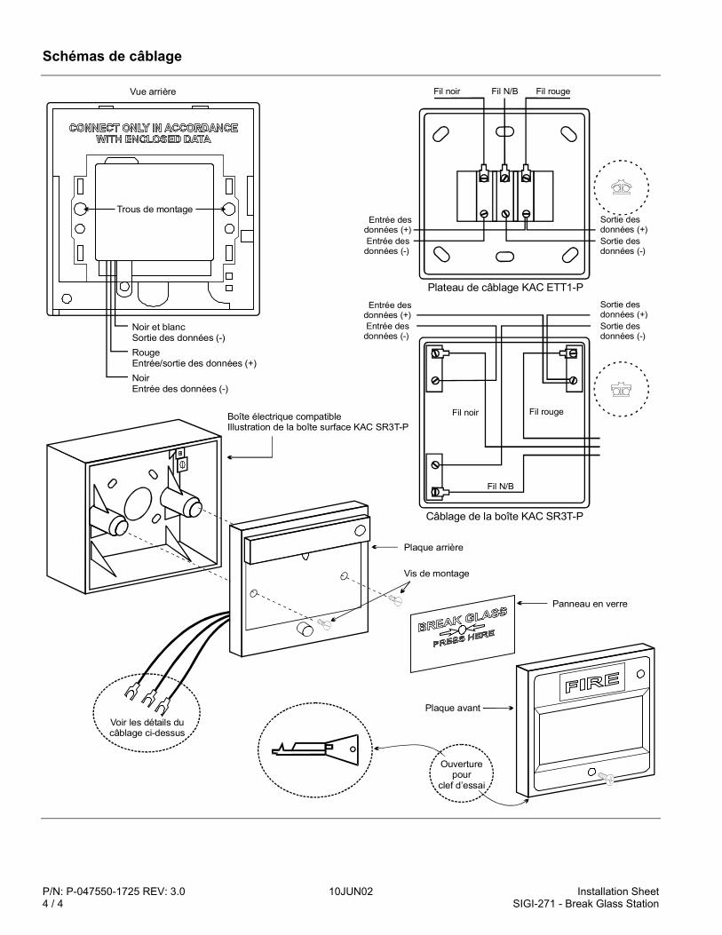
P/N: P-047550-1725 REV: 3.0 10JUN02 Installation Sheet4 / 4 SIGI-271 - Break Glass Station
Schémas de câblage
Rouge (+)Entrée/sortie des données
Noir (-)Entrée des données
Noir et blanc (-)Sortie des données
Trous de montage
Vue arrière
Entrée desdonnées (+)Entrée des
données (-)
Entrée desdonnées (+)Entrée des
données (-)
Fil noir
Fil noir
Plateau de câblage KAC ETT1-P
Fil N/B
Fil N/B Fil rouge
Fil rouge
Sortie desdonnées (+)Sortie desdonnées (-)
Sortie desdonnées (+)Sortie desdonnées (-)
Câblage de la boîte KAC SR3T-P
Voir les détails ducâblage ci-dessus
Boîte électrique compatibleIllustration de la boîte surface KAC SR3T-P
Panneau en verre
Vis de montage
Plaque avant
Ouverture pour
clef d’essai
Plaque arrière
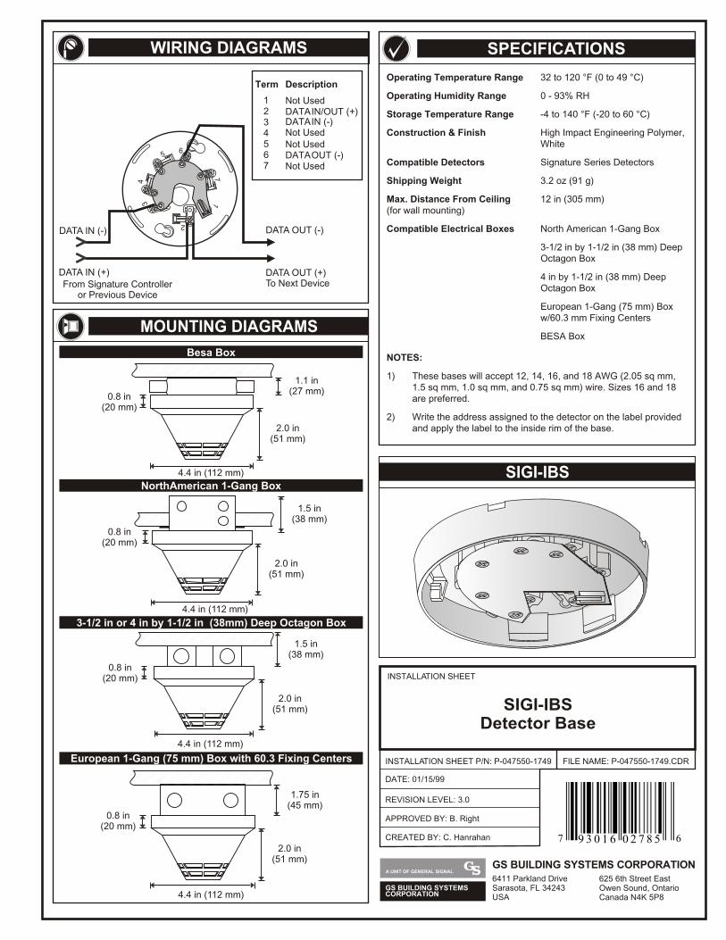
56
34
17
2
DATA OUT (-)
DATA OUT (+)To Next DeviceFrom Signature Controller
or Previous Device
DATA IN (-)
DATA IN (+)
Term
1 Not Used
45
DATA IN (-)
Not Used
7 Not Used
2 DATA IN/OUT (+)3
Not Used
6 DATA OUT (-)
DescriptionOperating Temperature Range 32 to 120 °F (0 to 49 °C)
Operating Humidity Range 0 - 93% RH
Storage Temperature Range -4 to 140 °F (-20 to 60 °C)
Construction & Finish High Impact Engineering Polymer, White
Compatible Detectors Signature Series Detectors
Shipping Weight 3.2 oz (91 g)
Max. Distance From Ceiling 12 in (305 mm)(for wall mounting)
Compatible Electrical Boxes North American 1-Gang Box
3-1/2 in by 1-1/2 in (38 mm) Deep Octagon Box
4 in by 1-1/2 in (38 mm) Deep Octagon Box
European 1-Gang (75 mm) Box w/60.3 mm Fixing Centers
BESA Box
NOTES:
1) These bases will accept 12, 14, 16, and 18 AWG (2.05 sq mm, 1.5 sq mm, 1.0 sq mm, and 0.75 sq mm) wire. Sizes 16 and 18 are preferred.
2) Write the address assigned to the detector on the label provided and apply the label to the inside rim of the base.
SIGI-IBS
SPECIFICATIONSWIRING DIAGRAMS
MOUNTING DIAGRAMS
4.4 in (112 mm)
1.1 in(27 mm)
2.0 in(51 mm)
0.8 in(20 mm)
Besa Box
4.4 in (112 mm)
1.5 in(38 mm)
2.0 in(51 mm)
0.8 in(20 mm)
NorthAmerican 1-Gang Box
4.4 in (112 mm)
1.5 in(38 mm)
2.0 in(51 mm)
0.8 in(20 mm)
3-1/2 in or 4 in by 1-1/2 in (38mm) Deep Octagon Box
European 1-Gang (75 mm) Box with 60.3 Fixing Centers
4.4 in (112 mm)
1.75 in(45 mm)
2.0 in(51 mm)
0.8 in(20 mm)
INSTALLATION SHEET
INSTALLATION SHEET P/N: P-047550-1749
REVISION LEVEL: 3.0
FILE NAME: P-047550-1749.CDR
SIGI-IBSDetector Base
DATE: 01/15/99
CREATED BY: C. Hanrahan
APPROVED BY: B. Right
GS BUILDING SYSTEMSCORPORATION
A UNIT OF GENERAL SIGNALGS BUILDING SYSTEMS CORPORATION6411 Parkland DriveSarasota, FL 34243USA
625 6th Street EastOwen Sound, OntarioCanada N4K 5P8
7 69 3 0 1 6 0 2 7 8 5
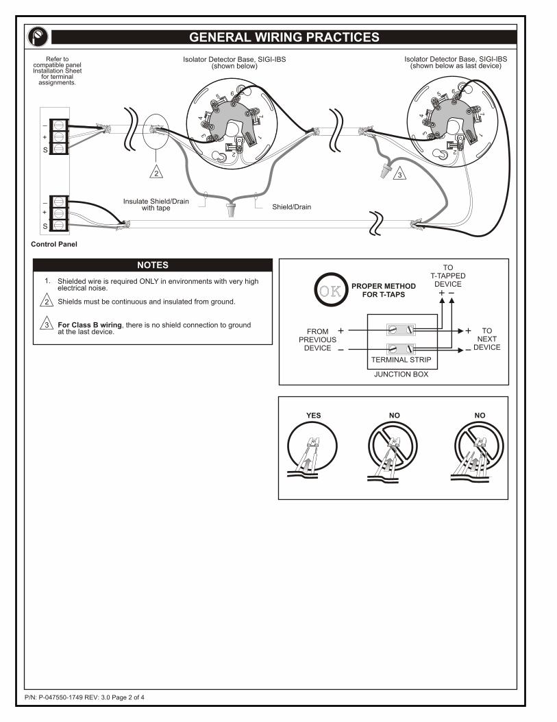
P/N: P-047550-1749 REV: 3.0 Page 2 of 4
+
+
_
_
S
S
Isolator Detector Base, SIGI-IBS(shown below)
Isolator Detector Base, SIGI-IBS(shown below as last device)
Insulate Shield/Drainwith tape Shield/Drain
Control Panel
2 3
NOYES NO
OKOK
JUNCTION BOX
TERMINAL STRIP
FROMPREVIOUS
DEVICE
TONEXT
DEVICE
TOT-TAPPEDDEVICEPROPER METHOD
FOR T-TAPS
Shielded wire is required ONLY in environments with very highelectrical noise.
1.
2 Shields must be continuous and insulated from ground.
3 For Class B wiring, there is no shield connection to groundat the last device.
NOTES
GENERAL WIRING PRACTICES
Refer tocompatible panelInstallation Sheet
for terminalassignments.
56
34
17
2
56
34
17
2
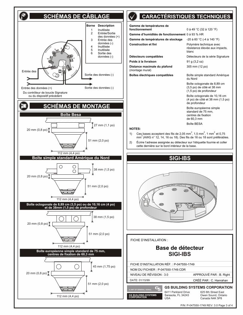
GS BUILDING SYSTEMSCORPORATION
A UNIT OF GENERAL SIGNALGS BUILDING SYSTEMS CORPORATION6411 Parkland DriveSarasota, FL 34243USA
625 6th Street EastOwen Sound, OntarioCanada N4K 5P8
DATE: 01/15/99
Gamme de températures de fonctionnement 0 à 49 C (32 à 120 F)
Gamme d’humidités de fonctionnement 0 à 93 % HR
Gamme de températures de stockage -20 à 60 C (-4 à 140 F)
Construction et fini Polymère technique avecrésistance élevée aux impacts, blanc
Détecteurs compatibles Détecteurs de la série Signature
Poids à la livraison 91 g (3,2 oz)
Distance maximale du plafond 305 mm (12 po)(montage mural)
Boîtes électriques compatibles Boîte simple standard Amérique du Nord
Boîte octogonale de 8,89 cm(3,5 po) de côté et 38 mm(1,5 po) de profondeur
Boîte octogonale de 10,16 cm(4 po) de côté et 38 mm (1,5 po) de profondeur
Boîte européenne simplestandard de 75 mm, centres de fixation de 60,3 mm
Boîte BESA
NOTES: 1) Ces bases acceptent des fils de 2,05 mm , 1,5 mm , 1 mm et 0,75
mm (AWG n 12, 14, 16 ou 18). Des fils de 16 ou 18 sont préférables.
2) Écrire l’adresse assignée au détecteur sur l’étiquette fournie et coller cette dernière sur le bord intérieur de la base.
° °
° °
2 2 2
2°
SIGI-IBS
CARACTÉRISTIQUES TECHNIQUES
P/N: P-047550-1749 REV: 3.0 Page 3 of 4
SCHÉMAS DE CÂBLAGE
112 mm (4,4 po)
27 mm (1,1 po)
51 mm (2,0 po)
20 mm (0,8 po)
Boîte Besa
112 mm (4,4 po)
38 mm (1,5 po)
51 mm (2,0 po)
20 mm (0,8 po)
Boîte simple standard Amérique du Nord
112 mm (4,4 po)
38 mm (1,5 po)
51 mm (2,0 po)
20 mm (0,8 po)
Boîte octogonale de 8,89 cm (3,5 po) ou de 10,16 cm (4 po)et de 38mm (1,5 po) de profondeur
112 mm (4,4 po)
45 mm (1,75 po)
51 mm (2,0 po)
20 mm (0,8 po)
Boîte européenne simple standard de 75 mm,centres de fixation de 60,3 mm
Entrée des
Entrée des données (+)
Du contrôleur de boucle Signatureou du dispositif précédent
Sortie des données (-)
Sortie des données (-)
Borne Description
1 Inutilisée2 Entrée/Sortie
des données (+)3 Entrée des
données (-)4 Inutilisée5 Inutilisée6 Sortie des
données (-)
SCHÉMAS DE MONTAGE
FICHE D’INSTALLATION :
FICHE D’INSTALLATION RÉF. : P-047550-1749
NOM DU FICHIER : P-047550-1749.CDR
NIVEAU DE RÉVISION : 3.0
CRÉÉ PAR : C. Hanrahan
APPROUVÉ PAR : B. Right
Base de détecteurSIGI-IBS
56
34
17
2
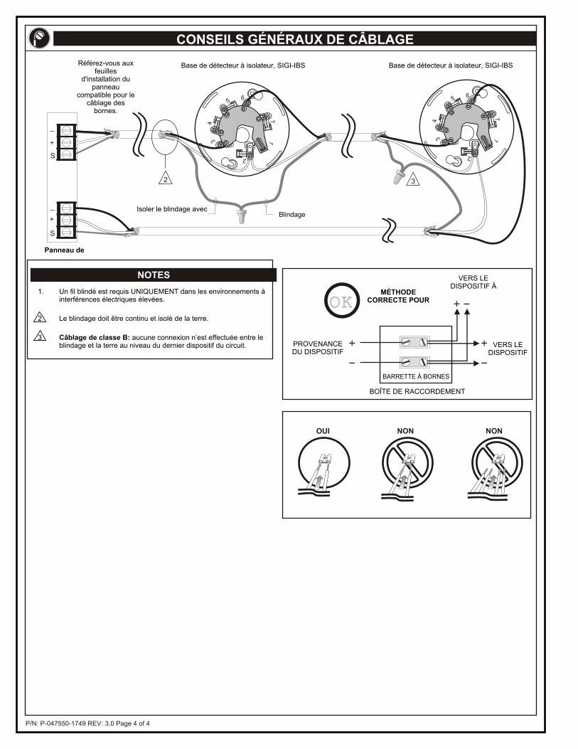
P/N: P-047550-1749 REV: 3.0 Page 4 of 4
NONOUI NON
NOTES
CONSEILS GÉNÉRAUX DE CÂBLAGE
+
+
_
_
S
S
2 3
Base de détecteur à isolateur, SIGI-IBS Base de détecteur à isolateur, SIGI-IBS
Isoler le blindage avec Blindage
Panneau de
OKOKMÉTHODE
CORRECTE POUR
VERS LE DISPOSITIF À
VERS LE DISPOSITIF
PROVENANCEDU DISPOSITIF
BARRETTE À BORNES
BOÎTE DE RACCORDEMENT
1. Un fil blindé est requis UNIQUEMENT dans les environnements à interférences électriques élevées.
2 Le blindage doit être continu et isolé de la terre.
3 Câblage de classe B: aucune connexion n’est effectuée entre le blindage et la terre au niveau du dernier dispositif du circuit.
56
34
17
2
56
34
17
2
Référez-vous aux feuilles
d'installation du panneau
compatible pour le câblage des
bornes.