Embed Size (px)
Citation preview

Copyrights 2010 Fujitsu General Limited, Sales Division, All rights reserved. Copyrights 2010 Fujitsu General Limited, Sales Division, All rights reserved.
02_VRF Network Design
1

Copyrights 2010 Fujitsu General Limited, Sales Division, All rights reserved.
2
Transmission line
2. Connectable to the Module Link network
(“Module link”)
・Outdoor Unit
1. Connectable to the LonWorks® - Network
(“transmission line”)
・Indoor Unit
・Outdoor Unit (Master)
・System Controller
・Touch Panel Controller
・Central Remote Controller
・Network Converter
-(for single split system)
-(for Group Remote Controller)
・Network Converter for LonWorks®
・Service Tool
・Web Monitoring Tool
・Signal Amplifier (*) * Design the signal amplifier after bring out
the transmission line
■ WIRING SYSTEM of VRF V-II
3. Connect for Remote control network
(“Remote controller line”)
・Wired Remote Controller
・Simple Remote Controller
・External Switch Controller
・Wireless Remote Controller
Module link
Remote controller link
VRF Network

Copyrights 2010 Fujitsu General Limited, Sales Division, All rights reserved.
3
Transmission Wiring Flow
Module link Network
Remote control Network
-Wired Remote controller connection-
-Simple Remote Controller connection-
-External Switch Controller connection-
LonWorks® Network - Connected product restrictions -
- Transmission line design -
- Signal amplifier connection -
- Terminal resistor connection -
- Network converter connection -

Copyrights 2010 Fujitsu General Limited, Sales Division, All rights reserved.
4
LonWorks® Network
Copyrights 2010 Fujitsu General Limited, Sales Division, All rights reserved.
5
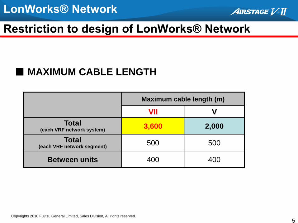
Restriction to design of LonWorks® Network
■ MAXIMUM CABLE LENGTH
Maximum cable length (m)
VII V
Total (each VRF network system)
3,600 2,000
Total (each VRF network segment)
500 500
Between units 400 400
LonWorks® Network

Copyrights 2010 Fujitsu General Limited, Sales Division, All rights reserved.
6
Restriction to design of LonWorks® Network
Maximum connectable units (each VRF network system)
VII V
Outdoor unit 100 unit 100 count
Indoor unit 400 unit 400 unit
■ MAXIMUM CONNECTABLE UNITS
LonWorks® Network
Outdoor Units Units / Counts - explanation
VII V
only Master 1 unit 1 count
Master & Slave 1 2 units 4 counts
Master & Slave 1 & Slave 2
3 units 5 counts

Copyrights 2010 Fujitsu General Limited, Sales Division, All rights reserved.
7
Restriction to design of LonWorks® Network
■ two different limitations :
1. traffic limitation
-> max. 100 Outdoor Units (V-II-Series)
-> max. 100 Counts (V-Series)
2. network segment limitation
-> max. 64 units (nodes)
-> LonWorks® network regulation
LonWorks® Network

Copyrights 2010 Fujitsu General Limited, Sales Division, All rights reserved.
8
CENTRAL CONTROL
Product System
Controller
Touch Panel
Controller
Central Remote
Controller
Group Remote
Controller
Design
Product
Name
UTY-APGX UTY-DTGY
UTY-DTGG
UTY-DCGY
UTY-DCGG
UTY-CGGY
UTY-CGGG
Feature Indoor unit
1,600units
Outdoor unit :
400units
Indoor unit
400units
Outdoor unit
100units
Indoor unit
100 units
Indoor unit
96units
Controller Line up
LonWorks® Network

Copyrights 2010 Fujitsu General Limited, Sales Division, All rights reserved.
9
ADAPTOR CONVERTOR SERVICE &
MONITORING
Product Signal
Amplifier
Network
Convertor
Network
Convertor
for
LonWorks®
BACnet
Gateway
Service
Tool
WEB
Monitoring
Tool
Design
Product
Name
UTY-VSGX UTY-VGGX UTY-VLGX UTY-ABGX UTY-ASGX UTY-AMGX
Feature
Adaptor / Convertor / Service and Monitoring Line up
1.Convertor for
Split system
2.Convertor for
group remote controller
It uses when
system expand
more than 500m or
64 units
Connection to
LonWorks® BMS.
Diagnose for
service and
commissioning on
site
Monitoring the
operation status via
internet
Connection to
BACnet BMS.
LonWorks® Network

Copyrights 2010 Fujitsu General Limited, Sales Division, All rights reserved.
10
■ THE MAXIMUM CONNECTABLE UNITS
*1: Maximum 100 Refrigerant system.
*2: Maximum connectable indoor unit number per one Network Convertor. (Please check the System Diagram (Item:5-3-2) for proper configuration)
*3: A maximum of 4 Network Convertors for LONWORKS® can be connected to 1 BMS.
*4 For “16 / system”, the number of Network Convertor for LonWorks® and BACnet® Gateway is also included.
Model Necessary
Equipment
The number
that can be
connected
The number of
management
[Indoor units]
Connectable
outdoor unit
Controller Central
Controller
System Controller UTY-APGX USB Adaptor 1 / system 1600 (×4 VRF Network)
400 (×4 VRF Network)
Group Remote Controller UTY-CGG* UTY-VGGX 4 / UTY-VGGX 96 (2 refrigerants system)
6
16 / system
*4 Touch Panel Controller UTY-DTG* - 400
100 Central Remote Controller UTY-DCG* - 100
Adaptor Signal Amplifier UTY-VSGX - 8 / system - -
Convertor Network Convertor UTY-VGGX - 100 / system *1 - -
Network Convertor for
LonWorks® *3 UTY-VLGX - 1 / system 128 *2 100
BACnet® Gateway UTY-ABGX USB Adaptor 1 / system 1600 (×4 VRF Network)
400 (×4 VRF Network)
Service and
Maintenance
Service Tool UTY-ASGX USB Adaptor 1 / system
400 100
Web Monitoring Tool UTY-AMGX USB Adaptor 1600 (×4 VRF Network)
400 (×4 VRF Network)
LonWorks® Network
Using communication PCB Including product PCB Including USB Adaptor

Copyrights 2010 Fujitsu General Limited, Sales Division, All rights reserved.
11
Transmission line

Copyrights 2010 Fujitsu General Limited, Sales Division, All rights reserved.
12
Please refer to Design and Technical
Manual (6-4-3).
��■ TRANSMISSION CABLE SPECIFICATIONS
Use the shielded wire specified and always ground it both end. 22AWG (0.65mm) Level 4 cable with shielded
(National Electrical Manufacturers Association (NEMA) Differs from the Category 4 specification proposed by
the Electronic Industries Association / Telecommunication Industry Association (EIA/TIA)
● Reference specifications for transmission cable
LonWorks® Network Specifications
Transmission line

Copyrights 2010 Fujitsu General Limited, Sales Division, All rights reserved.
Transmission line
Case 2
Case 1
Do you use
Indoor Unit Automatic Address Setting?
Case 1 or Case2 Only Case 2
No Yes
Decide to use feature of Automatic Address
Setting depending on system design
Design this to make
the transmission line
short.
Design this to make each
refrigerant system
independent.
13

Copyrights 2010 Fujitsu General Limited, Sales Division, All rights reserved.
14
What’s Indoor Unit Automatic Address setting ?
Network between outdoor units (route between Z1 and Z2) is disconnected.
1. The outdoor unit seeks a response from all indoor units via the connected network.
2. The indoor units responds to the outdoor unit via the connected network.
3. Addresses are assigned to the indoor units recognized by the outdoor unit.
4. The outdoor unit network recovers after the Refrigerant System 1 addressing is finished.
Transmission line
Terminal
Register
• INDOOR UNIT AUTOMATIC ADDRESS SETTING (F3-11)
Case 1 Case 2
Copyrights 2010 Fujitsu General Limited, Sales Division, All rights reserved.
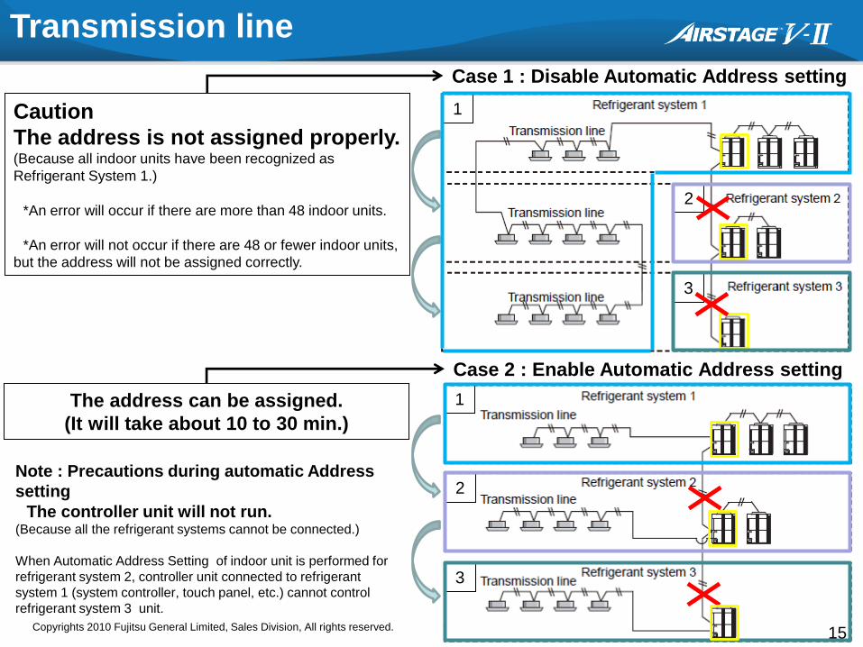
Case 2 : Enable Automatic Address setting
Case 1 : Disable Automatic Address setting
1
1
2
3
2
3
Caution
The address is not assigned properly. (Because all indoor units have been recognized as
Refrigerant System 1.)
*An error will occur if there are more than 48 indoor units.
*An error will not occur if there are 48 or fewer indoor units,
but the address will not be assigned correctly.
Note : Precautions during automatic Address
setting
The controller unit will not run. (Because all the refrigerant systems cannot be connected.)
When Automatic Address Setting of indoor unit is performed for
refrigerant system 2, controller unit connected to refrigerant
system 1 (system controller, touch panel, etc.) cannot control
refrigerant system 3 unit.
Transmission line
The address can be assigned.
(It will take about 10 to 30 min.)
15

Copyrights 2010 Fujitsu General Limited, Sales Division, All rights reserved.
16
Transmission wiring method Case 1
Transmission line

Copyrights 2010 Fujitsu General Limited, Sales Division, All rights reserved.
17
Transmission wiring method Case 2
Transmission line

Copyrights 2010 Fujitsu General Limited, Sales Division, All rights reserved.
18
■ Separation of Transmission line
Separate on the terminal for
transmission line.
Branch the transmission line as required by the
indoor unit side.
Transmission line
1 2 3
Connection of three or more lines may
cause poor communication for one
terminal. In this case, please use a
terminal box.
Bad Example
Do not use loop wiring.
This may lead to parts
damage
and erroneous
operation.
(Because the signal
will conflict and cause
the power to increase.)

Copyrights 2010 Fujitsu General Limited, Sales Division, All rights reserved.
19
Signal Amplifier
(UTY-VSGX)

Copyrights 2010 Fujitsu General Limited, Sales Division, All rights reserved.
20
LSI Micro-
computer LSI
Signal Amplifier (UTY-VSGX)
Regenerate signal output
■ Role of the Signal Amplifier (UTY-VSGX)
Communication reliability improvement
① Regenerate signal output
② Divide LonWorks® Network (Segment)
Remove noise
Regenerate
Signal Amplifier
Reception
Discards
defective data Transmission
Regenerate signal
No
Amp
Attenuation
Signal attenuation continues without a signal amplifier.
If the signal output entering the signal amplifier is
low, the microcomputer removes the noise
component from the signal. Therefore, the signal is
not output from the signal amplifier.
BAD Example
Remove
noise

Copyrights 2010 Fujitsu General Limited, Sales Division, All rights reserved.
21
Signal Amplifier (UTY-VSGX)
Divide into segments
VRF Network
VRF Network
■ Role of the Signal Amplifier (UTY-VSGX)
Communication reliability improvement
① Regenerate the signal output
② Divide LonWorks® Network (Segment)
・Insufficient Neuron chip drive
capacity
・Signal quantity increases
(signal opportunity) and possibility
of collision increases.
・The number of Neuron chip is kept
within capacity of drive.
・Possibility of collision is decreased.
This is because dividing into
segments decreases the number of
nodes within a segment.
Network
Segment 1
Network
Segment 1
Network
Segment 2
Network
Segment 3

Copyrights 2010 Fujitsu General Limited, Sales Division, All rights reserved.
22
Example 1
Confirm 1.
AB+BC+BD+DE+EF ≦ 500m
Confirm 2.
AC < 400m, AF < 400m
and CF < 400m.
①Signal Amplifier Installation Check Point
1. Make total transmission line length in each network segment 500 m or less.
2. Make the distance between units within 400 m.
Signal Amplifier (UTY-VSGX)
Example 2
Confirm 1.
AB+BC+BD ≦ 500m
DE+EF+EG ≦ 500m
Confirm 2.
AC < 400m, AD < 400m and CD<400m
DF < 400m, GF < 400m and DG<400m
GJ < 400m
JH < 400m
J
Example 2
Example 1

Copyrights 2010 Fujitsu General Limited, Sales Division, All rights reserved.
23
②Check Point for dividing the network into segments
The number of units included within each segment is 64 or less.
Note
Signal Amplifier (UTY-VSGX)
(1) Unit* means product connected for LonWorks® network directly.
(Group remote controller is not counted.)
(2) The signal amplifier is counted as 1 unit for each network segment.
Network segment 1
Number of unit *: 13
Network segment 2
Number of unit* : 64
Network segment 3
Number of unit* : 64
Network segment 4
Number of unit *: 64
Copyrights 2010 Fujitsu General Limited, Sales Division, All rights reserved.
24
Terminal Resistor

Copyrights 2010 Fujitsu General Limited, Sales Division, All rights reserved.
25
①The signal is reflected from the terminal device to become the noise component.
②If the reflected noise interferes with another signal, it disrupts the signal waveform.
③The disrupted waveform signal is not correctly recognized by the product.
In addition, since the output increases, there is a possibility the signal circuit board will be
damaged.
A terminal resistor to absorb the noise component is required to maintain overall network
signal reliability.
①
②
③
Be sure to set the terminal resistor according to specifications.
Set the terminal resistor for every network segment (NS).
● If terminal resistor is set in multiple devices, the overall communication system may be damaged.
● If terminal resistor is not set in a device, abnormal communication may occur.
Caution
Terminal Resistor
Terminal Resistor

Copyrights 2010 Fujitsu General Limited, Sales Division, All rights reserved.
26
5 cm 5 cm
Terminal resistor installation location
Terminal Resistor
SET 5 Terminal resistor Remarks
4
OFF Disable (Factory setting)
ON Enable -
1. Install in signal amplifier
2. Outdoor Dip Switch
Install 1 terminal resistor
for each segment.
Terminal resistor : ON
Terminal resistor : ON
Connect of Terminal resistor
Connect of Terminal resistor

Copyrights 2010 Fujitsu General Limited, Sales Division, All rights reserved.
27
Measure the resistance of the signal amplifier terminal
and the terminal of the indoor and outdoor units
connected farthest away from the device where
terminal resistor is measured.
A value from the table is displayed, depending on the
distance from the signal amplifier and the device where
the terminal resistor is set.
This value is an estimate.
Transmission cable connecting indoor units,
outdoor units, and signal amplifiers
Do not turn on the power if the resistance between the terminals of the transmission
cable is abnormal. Otherwise, the circuit board may be damaged.
Terminal Resistor
■ Confirmation

Copyrights 2010 Fujitsu General Limited, Sales Division, All rights reserved.
28
Network Convertor
(UTY-VGGX)

Copyrights 2010 Fujitsu General Limited, Sales Division, All rights reserved.
29
■ Network Convertor
① Group remote controller (UTY-CGGY) connection
② Single split, BIG MULTI connection
Max. connectable 4 Group Remote Controllers *)
Network Convertor (UTY-VGGX)
Up to a total of 16 Network Convertors (UTY-VGGX)
Central Remote Controller, Touch Panel Controllers,
Network Convertor for LonWorks® and BACnet ®
Gateway can be connected in a single VRF network
system.
*)2 refrigerant circuits can be covered by a single Network Convertor.

Copyrights 2010 Fujitsu General Limited, Sales Division, All rights reserved.
30
■ Network Convertor
① Group remote controller (UTY-CGGY) connection
② Single split, BIG MULTI connection
Max. connectable 16 single indoor units
Up to 100 network convertors can be
connected in one VRF network system.
* A single network convertor is considered as a single
refrigerant system, irrespective of the number of
connected single models.
Network Convertor (UTY-VGGX)

Copyrights 2010 Fujitsu General Limited, Sales Division, All rights reserved.
31
• Total remote controller cable length when connected to one converter 100m
Network Convertor (UTY-VGGX)
Maximum wiring length
Total length of group remote controller cable to convertor. 100m
Wiring Design

Copyrights 2010 Fujitsu General Limited, Sales Division, All rights reserved.
32
1. When Wired Remote Controller is supplied
Check the RC Number
*Connectable if RC number is the same as below
2. If it is not supplied or RC Number is different from
the above number Please purchase the following model Wired Remote
Controller
Network Convertor (UTY-VGGX)
Model name
UTB-*UB
Wiring Design
Caution Indoor units with G as the 4th digit of the model
name cannot be connected.
*Indoor units of 8 Room Multi cannot be connected.
Indoor units corresponding to Wired remote controller
(Indoor unit with supplied Wired remote controller
or with option setting for it)
・Connectable model
A U Y G 1 2 L V L A
・Connectable Wired Remote Controller
RC Number
AR-3TA**
Maximum wiring length
Remote controller to UTY – VGGX 100m
Indoor unit to UTY - VGGX 100m
Connect a single big multi system to a single
network convertor. Do not connect two big multi
systems, or a big multi system and a single model
system.
・Note
Copyrights 2010 Fujitsu General Limited, Sales Division, All rights reserved.
33
Module link Network

Copyrights 2010 Fujitsu General Limited, Sales Division, All rights reserved.
34
��■ TRANSMISSION WIRING SPECIFICATIONS
* Same as LonWorks® Network
Master Unit Slave Unit Slave Unit
A B C
Wiring rule :
AB ≦ 18 (m), BC ≦ 18 (m)
Module link Network

Copyrights 2010 Fujitsu General Limited, Sales Division, All rights reserved.
35
Module link Network
SET 3 Outdoor unit
Address Remarks
1 2
OFF OFF 0 Master unit only
OFF ON 1 Slave unit 1
ON OFF 2 Slave unit 2
ON ON - Forbidden
SET 3 Number of
connectable
outdoor units
Remarks 3 4
OFF OFF 0 Master unit only
OFF ON 1 1 Slave unit connected
ON OFF 2 2 Slave units connected
ON ON - Forbidden
Outdoor unit address setting
Number of slave units setting for outdoor unit*
* Master unit only
Dip switch settings
If the dip switches are not set correctly,
the initialization signal among the
outdoor units will not end, so the
outdoor units will not start operating.
Transmission cable connecting outdoor units in a refrigerant system
The resistance between the terminals of
the transmission cable is 45-60Ω.
This value is an estimate.

Copyrights 2010 Fujitsu General Limited, Sales Division, All rights reserved.
36
Remote control Network

Copyrights 2010 Fujitsu General Limited, Sales Division, All rights reserved.
37
INDIVIDUAL CONTROL
Product Wired Remote
Controller
Simple Remote
Controller
External Switch
Controller
Wireless Remote
Controller
Design
Product
Name
UTY-RNKY
UTY-RNKG
UTY-RNKYT
UTY-RSKY
UTY-RSKG
UTY-RHKY
UTY-RHKG
UTY-RSKYT
UTY-RHKYT
UTY-TEKX UTY-LNHY
UTY-LNHG
Feature Indoor unit
16 units
Indoor unit
16 units
Indoor unit
16 units
Air Conditioner
switching with
interlink to external
signal.
Controller Line up
Remote control Network

Copyrights 2010 Fujitsu General Limited, Sales Division, All rights reserved.
38
Remote control Network
MODEL TYPE CONNECT TO WIRE SIZE SPECIFICATIONS
Wired Remote
ControllerIndoor unit
Simple Remote
ControllerIndoor unit
Indoor unitRemote controller
cable0.33 mm
2 Shielded, Polar 3core
External input deviceExternal input
cable0.33 mm
2 Shielded, Polar 2core, Twisted pair
Sheathed vinyl cable, Polar 3core (Use shielded cable in accordance with local rules )
External Switch
Controller
Remote controller
cable *10.33 mm
2
■ Remote controller cable specification
Model The number that can be connected
Controller Individual
Controller
Wireless Remote Controller UTY - LNH* -
Wired Remote Controller UTY - RNK*
2 / Remote control group
Simple Remote Controller
(with operation mode)
UTY – RSK*
Simple Remote Controller
(without operation mode)
UTY – RHK*
External Switch Controller UTY – TEKX
■ THE MAXIMUM CONNECTABLE UNITS
*1) 10 m of Remote controller cable is included in product

Copyrights 2010 Fujitsu General Limited, Sales Division, All rights reserved.
39
WIRED REMOTE CONTROLLER (UTY-RNK*) (UTY-RNKYT)
SYSTEM DIAGRAM & WIRING DESIGN
Multiple Indoor Unit
Max. 16
A ≦500 m B+C ≦500 m
2 remote controller 1 remote controller
B C
A
D+E+F+G ≦500m
Y1 : 12V
Y2 : Signal
Y3 : COM
D E F G
SIMPLE REMOTE CONTROLLER (UTY-RSK*) / (UTY-RHK*) / (UTY-R*KYT)
Remote control Network

Copyrights 2010 Fujitsu General Limited, Sales Division, All rights reserved.
40
EXTERNAL SWITCH CONTROLLER (UTY - TEKX)
SYSTEM DIAGRAM & WIRING DESIGN
Less than 50 m Less than 50 m
Connection to external contacts
Wiring Design
System Diagram
Remote control Network

Copyrights 2010 Fujitsu General Limited, Sales Division, All rights reserved.
41
Thank you for listening