Embed Size (px)
Citation preview
Vibration
Calibration of Vibration Sensors
Vibration sensors are used in many applications in R&D, pro-duction, monitoring and maintenance work. Correct inter-pretation of results from measurements made using these sensors requires information about their sensitivity over the frequency range of interest. METAS is capable of calibrating vibration sensors with the required accuracy. For companies and accredited laboratories that have their own calibration equipment, METAS offers calibration of reference and work-ing standards combined with traceability to the national reference.
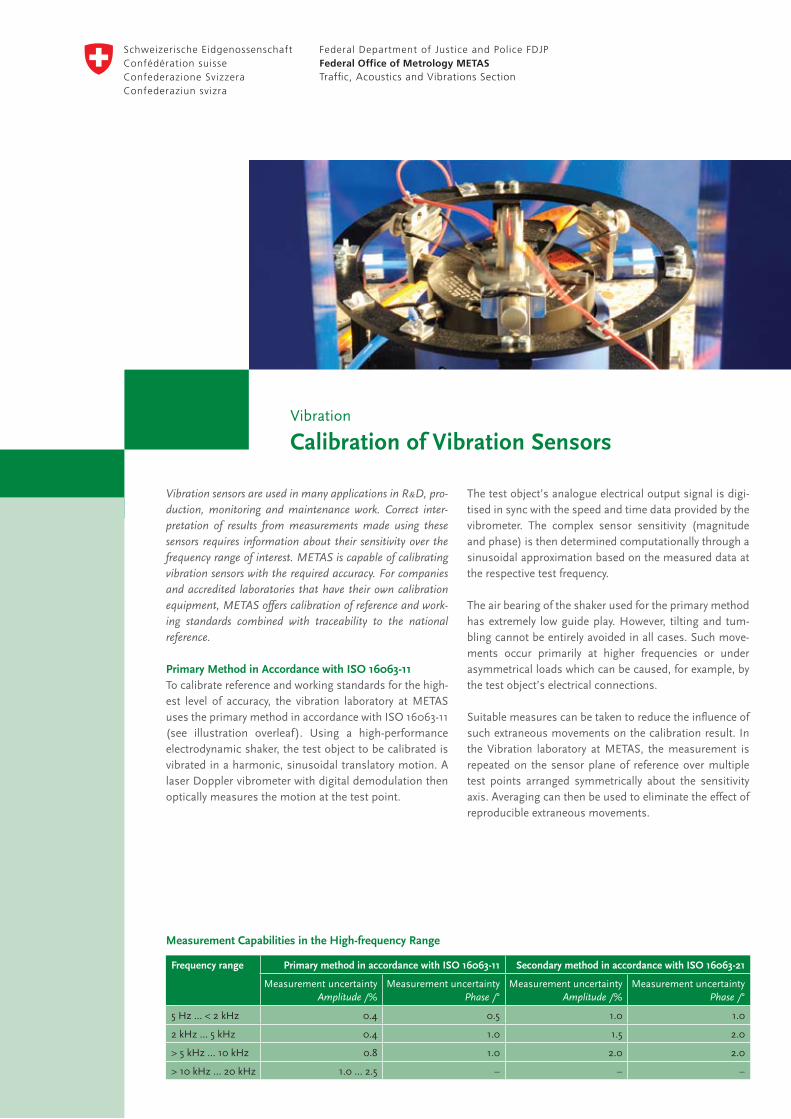
Primary Method in Accordance with ISO 16063-11To calibrate reference and working standards for the high-est level of accuracy, the vibration laboratory at METAS uses the primary method in accordance with ISO 16063-11 (see illustration overleaf). Using a high-performance electrodynamic shaker, the test object to be calibrated is vibrated in a harmonic, sinusoidal translatory motion. A laser Doppler vibrometer with digital demodulation then optically measures the motion at the test point.
The test object’s analogue electrical output signal is digi-tised in sync with the speed and time data provided by the vibrometer. The complex sensor sensitivity (magnitude and phase) is then determined computationally through a sinusoidal approximation based on the measured data at the respective test frequency.
The air bearing of the shaker used for the primary method has extremely low guide play. However, tilting and tum-bling cannot be entirely avoided in all cases. Such move-ments occur primarily at higher frequencies or under asymmetrical loads which can be caused, for example, by the test object’s electrical connections.
Suitable measures can be taken to reduce the influence of such extraneous movements on the calibration result. In the Vibration laboratory at METAS, the measurement is repeated on the sensor plane of reference over multiple test points arranged symmetrically about the sensitivity axis. Averaging can then be used to eliminate the effect of reproducible extraneous movements.
Measurement Capabilities in the High-frequency Range
Frequency range Primary method in accordance with ISO 16063-11 Secondary method in accordance with ISO 16063-21
Measurement uncertainty Amplitude /%
Measurement uncertainty Phase /°
Measurement uncertainty Amplitude /%
Measurement uncertainty Phase /°
5 Hz … < 2 kHz 0.4 0.5 1.0 1.0
2 kHz … 5 kHz 0.4 1.0 1.5 2.0
> 5 kHz … 10 kHz 0.8 1.0 2.0 2.0
> 10 kHz … 20 kHz 1.0 … 2.5 – – –
METAS is the national metrology institute of Switzerland. It realises and disseminates internationally harmonised and recognised measurement standards at the required accuracy.
The specialists in the vibration laboratory calibrate sensors, signal processing modules such as charge-to-voltage converters and display units as well as complete measurement chains.
May 2009. Subject to alteration.
Federal Office of Metrology METASLindenweg 50, CH-3003 Bern-Wabern, Telephone +41 31 32 33 111, www.metas.ch
ContactTelephone +41 31 32 33 111 [email protected]
Serviceswww.metas.ch/services
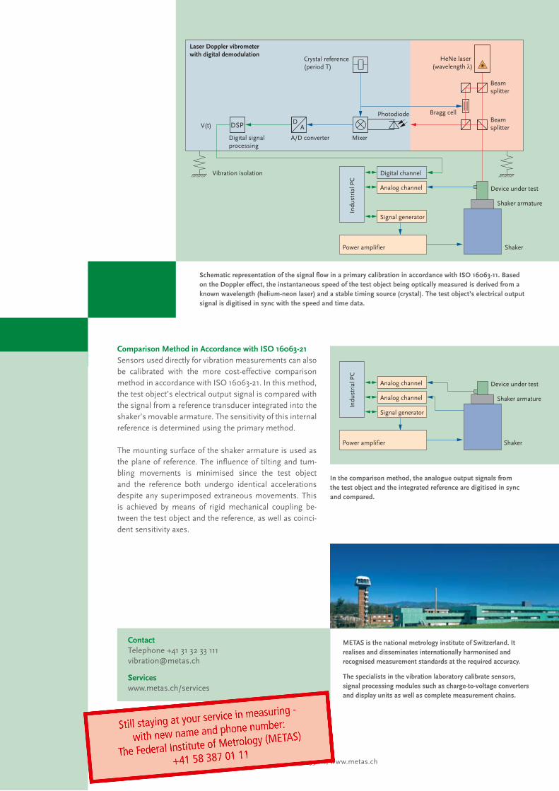
Comparison Method in Accordance with ISO 16063-21Sensors used directly for vibration measurements can also be calibrated with the more cost-effective comparison method in accordance with ISO 16063-21. In this method, the test object’s electrical output signal is compared with the signal from a reference transducer integrated into the shaker’s movable armature. The sensitivity of this internal reference is determined using the primary method.
The mounting surface of the shaker armature is used as the plane of reference. The influence of tilting and tum-bling movements is minimised since the test object and the reference both undergo identical accelerations despite any superimposed extraneous movements. This is achieved by means of rigid mechanical coupling be-tween the test object and the reference, as well as coinci-dent sensitivity axes.
DA
Indu
stri
al P
C
Power amplifier
Laser Doppler vibrometer with digital demodulation
Digital signal processing
A/D converter Mixer
PhotodiodeBeam splitter
Beam splitter
HeNe laser (wavelength λ)
Crystal reference (period T)
V(t)
Digital channel
Analog channel
Signal generator
DSP
Device under test
Shaker armature
Shaker
Vibration isolation
Bragg cell
Schematic representation of the signal flow in a primary calibration in accordance with ISO 16063-11. Based on the Doppler effect, the instantaneous speed of the test object being optically measured is derived from a known wavelength (helium-neon laser) and a stable timing source (crystal). The test object’s electrical output signal is digitised in sync with the speed and time data.
Power amplifier
Analog channel
Analog channel
Signal generator
Device under test
Indu
stri
al P
C
Shaker armature
Shaker
In the comparison method, the analogue output signals from the test object and the integrated reference are digitised in sync and compared.