Embed Size (px)
Citation preview
Abstract--Distributed Generation (DG) is predicted to play an
important role in the electric power system in the near future. It is widely accepted that micro turbine-generation are currently attracting lot of attention to meet users’ need in the distributed generation market. In order to investigate the ability of microturbine units in distribution systems, their efficient modeling is required. This paper presents a dynamic model of a micro- turbine generator system. The model is developed in the MATLLAB/Simulink and implemented in SimPowerSystems library. The model is built from the dynamics of each part with their interconnections. This simplified model is a useful tool for studying the various operational aspects of micro turbines. The performance of developed model is studied by connecting it to an isolated load.
Index Terms--Distributed generation, micro turbine,
permanent magnet synchronous machine, simulation, modeling, power conditioning.
I. INTRODUCTION HE fundamental concepts for the penetration of DG technologies are the high efficiency of the energy
conversion process and the limited emission of pollutants as compared to conventional power plants. Besides offering a higher flexibility and load management, they provide a number of significant local benefits. The integration of the increasing portion of DG within the existing infrastructure requires a full understanding of its impact on the distribution feeders and its interaction with the loads. Some of the operational aspects which require full understanding are voltage control, stability, system protection etc. Such studies require accurate modeling of Distributed Generation (DG) sources including distribution system [1].
Distributed generation using microturbine is a typical and practical solution because of its environment-friendliness and high energy efficiency [1], [2]. Various applications such as peak saving, co-generation, remote power and premium power will make its use world wide. An accurate model of the micro The authors are with the Department of Electrical Engineering, Indian Institute of technology Roorkee, Roorkee, Uttaranchal, INDIA (e-mail , [email protected], [email protected] ). 0-7803-9525-5/06/$20.00 ©2006 IEEE.
turbine is therefore required to analyze the mentioned impacts. Until now, only few works were undertaken on the modeling, simulation and control of micro turbines. There is also a lack of adequate information on their performances. A dynamic model for combustion gas turbine has been discussed in [2]-[6]. In these references, a combustion gas turbine model was used to represent the gas turbine dynamics, including speed, temperature, acceleration and fuel controls. However these works deal with heavy-duty gas turbine. Modeling of micro turbine was reported in [7] where the author developed a generic model of the grid connected micro turbine converter.
A non-linear model of the microturbine is considered and
implemented in NETOMAC software [8]. The dynamic behavior of the grid connected split shaft microturbine is discussed in [9].In [10] the load following performance and modeling of split shaft micro turbine is discussed A distribution system with some simple but practical control strategies is developed for the analysis of load-following service provided by microturbine [10].This paper presents single shaft microturbine generation system model developed in SimPowerSystems library of the MATLAB software.
II. MICROTURBINE GENERATION SYSTEM MODELING There are essentially two types of micro turbine designs.
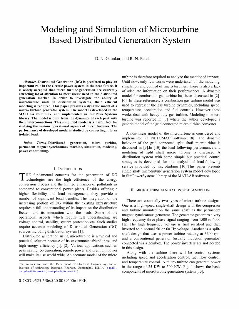
One is a high-speed single-shaft design with the compressor and turbine mounted on the same shaft as the permanent magnet synchronous generator. The generator generates a very high frequency three phase signal ranging from 1500 to 4000 Hz. The high frequency voltage is first rectified and then inverted to a normal 50 or 60 Hz voltage. Another is a split-shaft design that uses a power turbine rotating at 3600 rpm and a conventional generator (usually induction generator) connected via a gearbox. The power inverters are not needed in this design.
Along with the turbine there will be control systems including speed and acceleration control, fuel flow control, and temperature control. A micro turbine can generate power in the range of 25 KW to 500 KW. Fig. 1 shows the basic components of microturbine generation system [13].
Modeling and Simulation of Microturbine Based Distributed Generation System
D. N. Gaonkar, and R. N. Patel
T
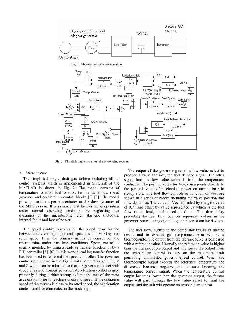
Fig. 1. Microturbine generation system.
Thermocouple Radiation shield
Temp. Control
Value Positioner Fuel System Combustor
No load Fuel Flow
Speed Governer
Accel. Control
Ref. Speed
Temp.Ref.
Vce Limits
Turbine Torqueoutput
Gas Turbine Dynamics
Turbine
Exhaust delay
Turbine
F1
F2F1=700*(1-u) FF2=550*(1-u) F
Fuel demand 2
1
1
0.2s+1
1
0.05s+1
1
2.5s+1
0.2
15s+1
1
0.4s+1
100
s
3.3s+1
0.5s
X.s+1
Y.s+Z
min-K--K-
0.5*(1-u)
f(u)
f(u)
f(u)
du/dt
0.8
0.23
Tr
1
0.01
2 Load reference
1
P.U. System Speedinput
Fig. 2. Simulink implementation of microturbine system.
A. Microturbine
The simplified single shaft gas turbine including all its control systems which is implemented in Simulink of the MATLAB is shown in Fig. 2. The model consists of temperature control, fuel control, turbine dynamics, speed governor and acceleration control blocks [2] [3]. The model presented in this paper concentrates on the slow dynamics of the MTG system. It is assumed that the system is operating under normal operating conditions by neglecting fast dynamics of the microturbine (e.g., start-up, shutdown, internal faults and loss of power).
The speed control operates on the speed error formed
between a reference (one per-unit) speed and the MTG system rotor speed. It is the primary means of control for the microturbine under part load conditions. Speed control is usually modeled by using a lead-lag transfer function or by a PID controller [3], [6]. In this work a lead lag transfer function has been used to represent the speed controller. The governor controls are shown in the Fig. 2 with parameters gain, X, Y and Z which can be adjusted so that the governor can act with droop or as isochronous governor. Acceleration control is used primarily during turbine startup to limit the rate of the rotor acceleration prior to reaching operating speed. If the operating speed of the system is close to its rated speed, the acceleration control could be eliminated in the modeling.
The output of the governor goes to a low value select to produce a value for Vce, the fuel demand signal. The other signal into the low value select is from the temperature controller. The per unit value for Vce, corresponds directly to the per unit value of mechanical power on turbine base in steady state. The fuel flow controls as function of Vce, are shown in a series of blocks including the valve position and flow dynamics. The value of Vce, is scaled by the gain value of 0.77 and offset by value represented by which is the fuel flow at no load, rated speed condition. The time delay preceding the fuel flow controls represents delays in the governor control using digital logic in place of analog devices.
The fuel flow, burned in the combustor results in turbine
torque and in exhaust gas temperature measured by a thermocouple. The output from the thermocouple is compared with a reference value. Normally the reference value is higher than the thermocouple output and this forces the output from the temperature control to stay on the maximum limit permitting uninhibited governor/speed control. When the thermocouple output exceeds the reference temperature, the difference becomes negative and it starts lowering the temperature control output. When the temperature control output becomes lower than the governor output, the former value will pass through the low value select to limit the output, and the unit will operate on temperature control.
B. Permanent Magnet Synchrones Machine (PMSM)
The model adopted for the generator is a 2 pole permanent magnet synchronous machine (PMSM) with a non-salient rotor [11]. At 1600 Hertz (96 000 rpm), the machine output power is 30 kW and its terminal line-to-line voltage is 480 V. The electrical and mechanical parts of the machine are each represented by a second-order state-space model. The model assumes that the flux established by the permanent magnets in the stator is sinusoidal, which implies that electromotive forces are sinusoidal. The following equations expressed in the rotor reference frame (dq frame) used to implement PM synchronous machine.
Electrical equations:
qrd
qd
dd
dd ipw
L
Li
L
Rv
Li
dt
d+−=
1
q
rdr
q
dq
qq L
pwipw
L
Li
L
Rv
Li
dt
d λ−−−=
1
))((5.1 qdqdqe iiLLipT −+= λ
Mechanical equations:
)(1Mrer TFwT
Jw
dt
d−−=
rwdt
d=
θ
Where
Lq, Ld : q and d axis inductances R : Resistance of the stator windings iq, id : q and d axis currents vq, vd : q and d axis voltages ωr : Angular velocity of the rotor λ : Flux induced by the permanent magnets in the stator windings. P : Number of pole pairs Te : Electromagnetic torque j : Combined inertia of rotor and load F : Combined viscous friction of rotor and load Θ : Rotor angular position Tm : Shaft mechanical torque.
C. Power Conditioning System
As discussed, single-shaft microturbines feature digital power controllers to convert the high frequency AC power produced by the generator into usable electricity. The high frequency AC is rectified to DC, inverted back to 60 or 50 Hz AC, and then filtered to reduce harmonic distortion. The power conditioning is a critical component in the single-shaft microturbine design and represents significant design challenges, specifically in matching turbine output to the required load. Power conditioning unit consists of a three-phase diode rectifier, a voltage source inverter (VSI) and LC filter.
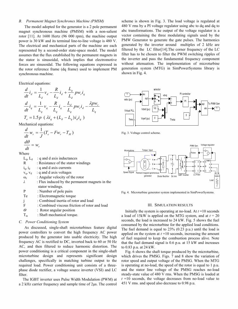
The IGBT inverter uses Pulse Width Modulation (PWM) at a 2 kHz carrier frequency and sample time of 2µs. The control
scheme is shown in Fig. 3. The load voltage is regulated at 480 V rms by a PI voltage regulator using abc to dq and dq to abc transformations. The output of the voltage regulator is a vector containing the three modulating signals used by the PMW Generator to generate the gate pulses. The harmonics generated by the inverter around multiples of 2 kHz are filtered by the LC filter[14].The corner frequency of the LC filter has to be chosen to filter the PWM switching ripples of the inverter and pass the fundamental frequency component without attenuation. The implementation of microturbine generation system (MTG) in SimPowerSystems library is shown in Fig. 4.
Virtual PLL Vdref (pu)
Vqref (pu)
vabc (pu)
vdvq PI controller
selector
To PWM Gen
Theta
1
dq0
abc
abc
dq0
Vd
00
Theta
PI
1
Fig. 3. Voltage control scheme.
Microturbine
Perment magnet synchronous generator Diode Recti fier Dc link
IGBT InverterSpeed Signal
C
Torque Input
Load
PWM Gen. Voltage regulator
A
B
C
+
-
Tm
mA
B
C
g
A
B
C
+
-
VabcA
B
C
a
b
c
A
B
C
A
B
C
LC Filter
A B C
Pulses
Fig. 4. Microturbine generator system implemented in SimPowerSystems.
III. SIMULATION RESULTS Initially the system is operating at no-load. At t =10 seconds
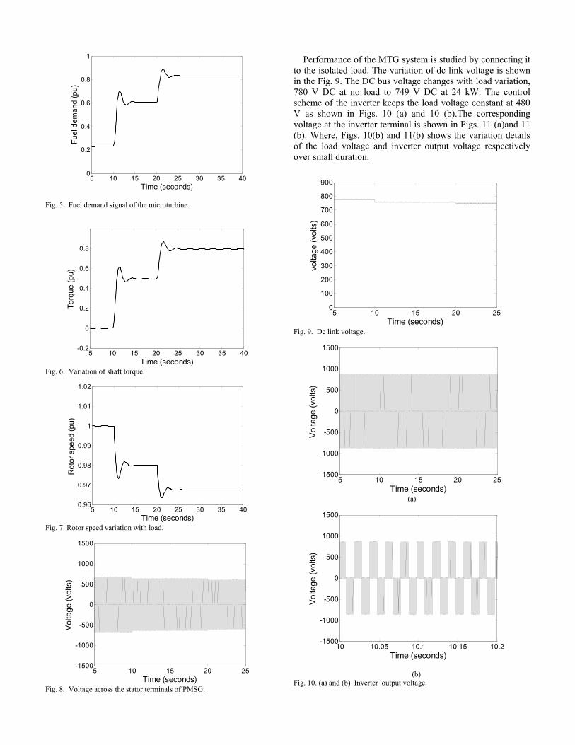
a load of 15kW is applied on the MTG system, and at t = 20 seconds, the load is increased to 24 kW. Fig. 5 shows the fuel consumed by the microturbine for the applied load conditions. The fuel demand is equal to 23% (0.23 p.u.) until the load is applied on the system at t =10 seconds, increasing the amount of fuel required to keep the combustion process alive. Note that the fuel demand signal is 0.6 p.u. at 15 kW and increases to 0.83 p.u. at 24 kW.
Fig. 6 shows the shaft torque produced by the microturbine, which drives the PMSG. Figs. 7 and 8 show the variation of rotor speed and output voltage of the PMSG. When the MTG is operating at no-load, the speed of the rotor is equal to 1 p.u. and the stator line voltage of the PMSG reaches no-load steady-state value of 480 V rms. When the PMSG is loaded at t =10 seconds, the voltage decreases from no-load value to 451 V rms. and speed also decrease to 0.98 p.u.
5 10 15 20 25 30 35 400
0.2
0.4
0.6
0.8
1
Time (seconds)
Fue
l dem
and
(pu)
Fig. 5. Fuel demand signal of the microturbine.
5 10 15 20 25 30 35 40-0.2
0
0.2
0.4
0.6
0.8
Time (seconds)
Tor
que
(pu)
Fig. 6. Variation of shaft torque.
5 10 15 20 25 30 35 400.96
0.97
0.98
0.99
1
1.01
1.02
Time (seconds)
Rot
or s
peed
(pu
)
Fig. 7. Rotor speed variation with load.
5 10 15 20 25-1500
-1000
-500
0
500
1000
1500
Time (seconds)
Vol
tage
(vo
lts)
Fig. 8. Voltage across the stator terminals of PMSG.
Performance of the MTG system is studied by connecting it
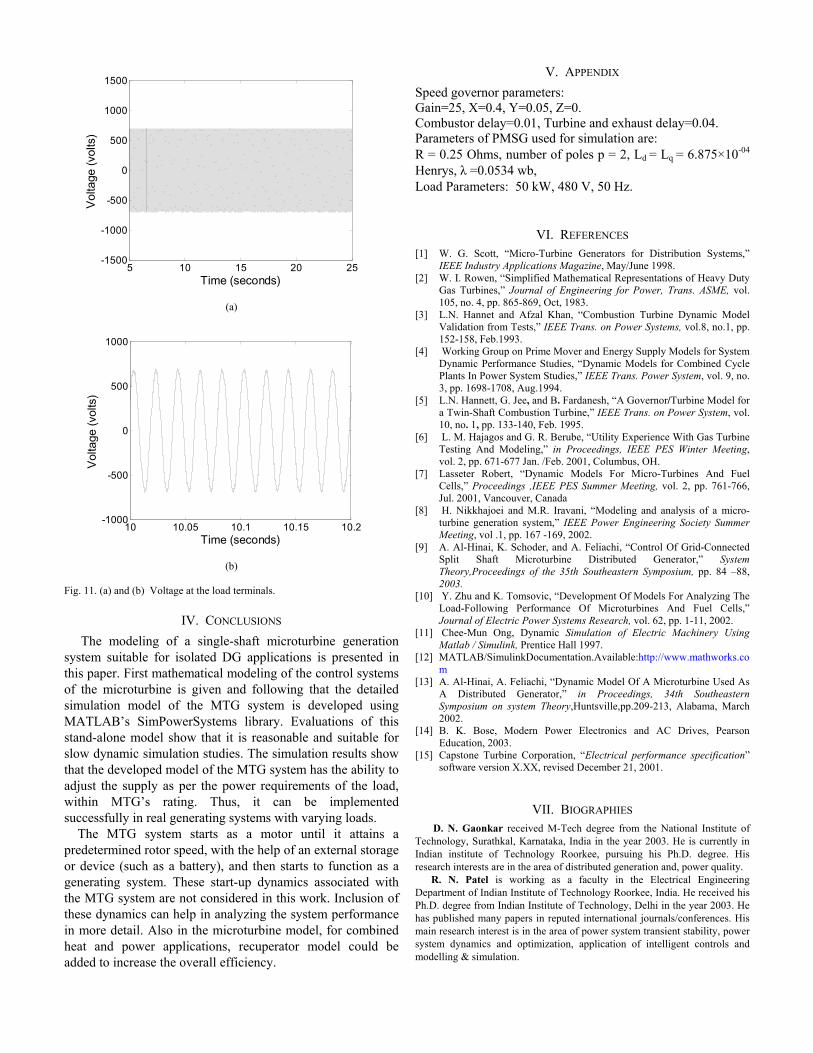
to the isolated load. The variation of dc link voltage is shown in the Fig. 9. The DC bus voltage changes with load variation, 780 V DC at no load to 749 V DC at 24 kW. The control scheme of the inverter keeps the load voltage constant at 480 V as shown in Figs. 10 (a) and 10 (b).The corresponding voltage at the inverter terminal is shown in Figs. 11 (a)and 11 (b). Where, Figs. 10(b) and 11(b) shows the variation details of the load voltage and inverter output voltage respectively over small duration.
5 10 15 20 250
100
200
300
400
500
600
700
800
900
Time (seconds)vo
ltage
(vo
lts)
Fig. 9. Dc link voltage.
5 10 15 20 25-1500
-1000
-500
0
500
1000
1500
Time (seconds)
Vol
tage
(vo
lts)
(a)
10 10.05 10.1 10.15 10.2-1500
-1000
-500
0
500
1000
1500
Time (seconds)
Vol
tage
(vo
lts)
(b) Fig. 10. (a) and (b) Inverter output voltage.
5 10 15 20 25-1500
-1000
-500
0
500
1000
1500
Time (seconds)
Vol
tage
(vo
lts)
(a)
10 10.05 10.1 10.15 10.2-1000
-500
0
500
1000
Time (seconds)
Vol
tage
(vo
lts)
(b) Fig. 11. (a) and (b) Voltage at the load terminals.
IV. CONCLUSIONS The modeling of a single-shaft microturbine generation
system suitable for isolated DG applications is presented in this paper. First mathematical modeling of the control systems of the microturbine is given and following that the detailed simulation model of the MTG system is developed using MATLAB’s SimPowerSystems library. Evaluations of this stand-alone model show that it is reasonable and suitable for slow dynamic simulation studies. The simulation results show that the developed model of the MTG system has the ability to adjust the supply as per the power requirements of the load, within MTG’s rating. Thus, it can be implemented successfully in real generating systems with varying loads.
The MTG system starts as a motor until it attains a predetermined rotor speed, with the help of an external storage or device (such as a battery), and then starts to function as a generating system. These start-up dynamics associated with the MTG system are not considered in this work. Inclusion of these dynamics can help in analyzing the system performance in more detail. Also in the microturbine model, for combined heat and power applications, recuperator model could be added to increase the overall efficiency.
V. APPENDIX Speed governor parameters: Gain=25, X=0.4, Y=0.05, Z=0. Combustor delay=0.01, Turbine and exhaust delay=0.04. Parameters of PMSG used for simulation are: R = 0.25 Ohms, number of poles p = 2, Ld = Lq = 6.875×10-04 Henrys, λ =0.0534 wb, Load Parameters: 50 kW, 480 V, 50 Hz.
VI. REFERENCES [1] W. G. Scott, “Micro-Turbine Generators for Distribution Systems,”
IEEE Industry Applications Magazine, May/June 1998. [2] W. I. Rowen, “Simplified Mathematical Representations of Heavy Duty
Gas Turbines,” Journal of Engineering for Power, Trans. ASME, vol. 105, no. 4, pp. 865-869, Oct, 1983.
[3] L.N. Hannet and Afzal Khan, “Combustion Turbine Dynamic Model Validation from Tests,” IEEE Trans. on Power Systems, vol.8, no.1, pp. 152-158, Feb.1993.
[4] Working Group on Prime Mover and Energy Supply Models for System Dynamic Performance Studies, “Dynamic Models for Combined Cycle Plants In Power System Studies,” IEEE Trans. Power System, vol. 9, no. 3, pp. 1698-1708, Aug.1994.
[5] L.N. Hannett, G. Jee, and B. Fardanesh, “A Governor/Turbine Model for a Twin-Shaft Combustion Turbine,” IEEE Trans. on Power System, vol. 10, no. 1, pp. 133-140, Feb. 1995.
[6] L. M. Hajagos and G. R. Berube, “Utility Experience With Gas Turbine Testing And Modeling,” in Proceedings, IEEE PES Winter Meeting, vol. 2, pp. 671-677 Jan. /Feb. 2001, Columbus, OH.
[7] Lasseter Robert, “Dynamic Models For Micro-Turbines And Fuel Cells,” Proceedings ,IEEE PES Summer Meeting, vol. 2, pp. 761-766, Jul. 2001, Vancouver, Canada
[8] H. Nikkhajoei and M.R. Iravani, “Modeling and analysis of a micro-turbine generation system,” IEEE Power Engineering Society Summer Meeting, vol .1, pp. 167 -169, 2002.
[9] A. Al-Hinai, K. Schoder, and A. Feliachi, “Control Of Grid-Connected Split Shaft Microturbine Distributed Generator,” System Theory,Proceedings of the 35th Southeastern Symposium, pp. 84 –88, 2003.
[10] Y. Zhu and K. Tomsovic, “Development Of Models For Analyzing The Load-Following Performance Of Microturbines And Fuel Cells,” Journal of Electric Power Systems Research, vol. 62, pp. 1-11, 2002.
[11] Chee-Mun Ong, Dynamic Simulation of Electric Machinery Using Matlab / Simulink, Prentice Hall 1997.
[12] MATLAB/SimulinkDocumentation.Available:http://www.mathworks.com
[13] A. Al-Hinai, A. Feliachi, “Dynamic Model Of A Microturbine Used As A Distributed Generator,” in Proceedings, 34th Southeastern Symposium on system Theory,Huntsville,pp.209-213, Alabama, March 2002.
[14] B. K. Bose, Modern Power Electronics and AC Drives, Pearson Education, 2003.
[15] Capstone Turbine Corporation, “Electrical performance specification” software version X.XX, revised December 21, 2001.
VII. BIOGRAPHIES D. N. Gaonkar received M-Tech degree from the National Institute of
Technology, Surathkal, Karnataka, India in the year 2003. He is currently in Indian institute of Technology Roorkee, pursuing his Ph.D. degree. His research interests are in the area of distributed generation and, power quality.
R. N. Patel is working as a faculty in the Electrical Engineering Department of Indian Institute of Technology Roorkee, India. He received his Ph.D. degree from Indian Institute of Technology, Delhi in the year 2003. He has published many papers in reputed international journals/conferences. His main research interest is in the area of power system transient stability, power system dynamics and optimization, application of intelligent controls and modelling & simulation.


