Embed Size (px)
Citation preview
Installation Manual and Operating Instructions
USBT202 Series
High Power USB Charging Port
True Blue Power® a division of
Mid-Continent Instrument Co., Inc.
Mid-Continent Instrument Co., Inc.
dba Mid-Continent Instruments and Avionics
9400 E. 34th Street N.
Wichita, KS 67226
PH (800) 821-1212
FX (316) 630-0723 Revision 1, June 15, 2018
© Copyright 2018 Mid-Continent
Instrument Co., Inc.
True Blue Power
Revision 1, June 15, 2018 2
SECTION 1 GENERAL DESCRIPTION
1.1 INTRODUCTION
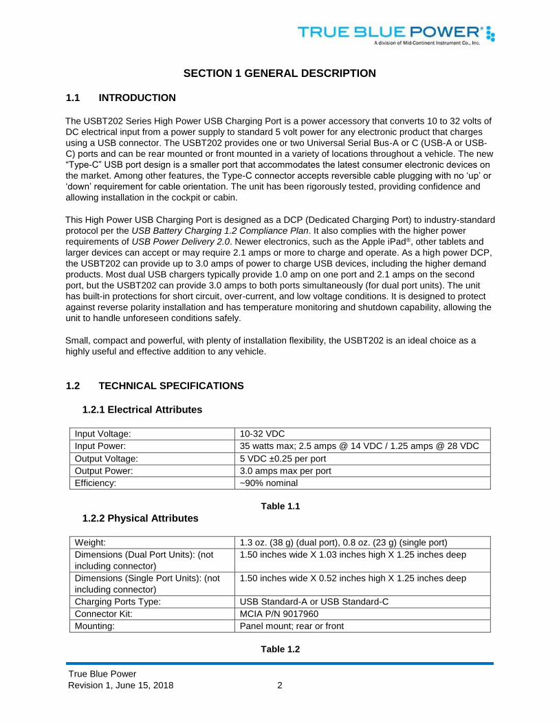
The USBT202 Series High Power USB Charging Port is a power accessory that converts 10 to 32 volts of
DC electrical input from a power supply to standard 5 volt power for any electronic product that charges
using a USB connector. The USBT202 provides one or two Universal Serial Bus-A or C (USB-A or USB-
C) ports and can be rear mounted or front mounted in a variety of locations throughout a vehicle. The new
“Type-C” USB port design is a smaller port that accommodates the latest consumer electronic devices on
the market. Among other features, the Type-C connector accepts reversible cable plugging with no ‘up’ or
‘down’ requirement for cable orientation. The unit has been rigorously tested, providing confidence and
allowing installation in the cockpit or cabin.
This High Power USB Charging Port is designed as a DCP (Dedicated Charging Port) to industry-standard
protocol per the USB Battery Charging 1.2 Compliance Plan. It also complies with the higher power
requirements of USB Power Delivery 2.0. Newer electronics, such as the Apple iPad®, other tablets and
larger devices can accept or may require 2.1 amps or more to charge and operate. As a high power DCP,
the USBT202 can provide up to 3.0 amps of power to charge USB devices, including the higher demand
products. Most dual USB chargers typically provide 1.0 amp on one port and 2.1 amps on the second
port, but the USBT202 can provide 3.0 amps to both ports simultaneously (for dual port units). The unit
has built-in protections for short circuit, over-current, and low voltage conditions. It is designed to protect
against reverse polarity installation and has temperature monitoring and shutdown capability, allowing the
unit to handle unforeseen conditions safely.
Small, compact and powerful, with plenty of installation flexibility, the USBT202 is an ideal choice as a
highly useful and effective addition to any vehicle.
1.2 TECHNICAL SPECIFICATIONS
1.2.1 Electrical Attributes
Input Voltage: 10-32 VDC
Input Power: 35 watts max; 2.5 amps @ 14 VDC / 1.25 amps @ 28 VDC
Output Voltage: 5 VDC ±0.25 per port
Output Power: 3.0 amps max per port
Efficiency: ~90% nominal
Table 1.1
1.2.2 Physical Attributes
Weight: 1.3 oz. (38 g) (dual port), 0.8 oz. (23 g) (single port)
Dimensions (Dual Port Units): (not
including connector)
1.50 inches wide X 1.03 inches high X 1.25 inches deep
Dimensions (Single Port Units): (not
including connector)
1.50 inches wide X 0.52 inches high X 1.25 inches deep
Charging Ports Type: USB Standard-A or USB Standard-C
Connector Kit: MCIA P/N 9017960
Mounting: Panel mount; rear or front
Table 1.2
True Blue Power
Revision 1, June 15, 2018 3
1.2.4 Versions
Non Lighted Lighted
Power Input
Location USB Connector
M6430202-1 M6430202-11 Rear Dual: Type A+Type C
M6430202-2 M6430202-12 Bottom
M6430202-3 M6430202-13 Rear Dual: Type C+Type C
M6430202-4 M6430202-14 Bottom
M6430202-5 M6430202-15 Rear Dual: Type A+Type A
M6430202-6 M6430202-16 Bottom
M6430202-7 M6430202-17 Rear Single: Type C
M6430202-8 M6430202-18 Bottom
M6430202-9 M6430202-19 Rear Single: Type A
M6430202-10 M6430202-20 Bottom
Table 1.4
SECTION 2 PRE-INSTALLATION CONSIDERATIONS
2.1 COOLING
No external cooling is required. The unit will become warm when in use. This is normal and within
operational parameters. No special mounting considerations are required; however, mounting to a metal
surface can help dissipate any heat generated and extend the life of the product.
2.2 EQUIPMENT LOCATION
The USBT202 High Power USB Charging Port is designed for mounting flexibility, allowing for installation
in the cockpit or in the cabin. It is designed for panel mounting and can be installed in a rectangular
configuration or, with an available installation kit, can be front mounted with a cosmetic cover plate. An
instrument mounting adapter bracket is also available to easily mount the unit in a standard 2.25 inch
round instrument opening that may already exist in the cockpit panel. There are two versions to choose
from which allow the input connector to be located either on the rear of the unit or from the bottom.
The unit can be mounted in any orientation. Clearance should be provided for the mating connector which
may require an additional inch beyond the rear of the unit.
2.3 ROUTING OF CABLES
Avoid sharp bends in cabling and routing near control cables. Avoid close proximity and contact with
vehicle structures, equipment or other obstructions that could chafe wires during operation and cause
undesirable effects.
2.4 LIMITATIONS
The USB Type-C interface is an exciting new connector for electronic devices. Beyond the physical format
of the Type-C connector, it also allows for a variety of interface options when communicating with
compatible devices. This device-to-charger communication is defined within the USB 3.1 Specification and
Power Delivery 2.0 standards. However, manufacturers of consumer electronic devices and/or cables may

True Blue Power
Revision 1, June 15, 2018 4
choose to implement proprietary versions or modifications of the USB standards to operate specifically
with their own charging equipment. The USBT202 has been tested with and supports a wide variety of
devices now emerging on the open market. However, compatibility with all devices may not be
guaranteed. True Blue Power continues to be proactive in evaluating new devices and strives to
continually improve the product as needed to serve the vast majority of USB Type-C electronic products.
2.5 MODIFICATIONS
Each USBT202 series High Power USB Charging Port (part number M6430202-( )) has a nameplate that
identifies the manufacturer, model, part number, description, and technical specifications of the unit. The
nameplate also includes the “MOD” or modification status representing notable changes in the design of
the unit.
SECTION 3 INSTALLATION PROCEDURES
3.1 GENERAL INFORMATION
This section contains interconnect diagrams, mounting dimensions and other information pertaining to the
installation of the USBT202 Single and Dual USB Charger. After installation of cabling and before
installation of the equipment, ensure that power and ground are applied to the proper pins specified in
Section 3.3.2, Pin Assignment Information.
3.2 UNPACKING AND INSPECTING EQUIPMENT
When unpacking this equipment, make a visual inspection for evidence of any damage that may have
occurred during shipment. The following parts should be included:
a. High Power USB Charging Port MCIA P/N M6430202-( )
b. Installation Manual
c. Connector Kit MCIA P/N 9017960
i. Mating Connector, 2-pin
ii. Pins (4) (2 required, 2 spares)
iii. Screws, #4-40 x 1/4 flat-head (2)
iv. Screws, #4-40 x 5/16 flat-head (2)
Optional Equipment Available:
a. Front Mount Installation Kit MCIA P/N 9017897
b. Instrument Mount Adapter Kit MCIA P/N 9017947
c. Rear Mount Installation Kit MCIA P/N 9017958
Equipment Not Provided:
a. Cable Harness Wire See Section 3.3.1 for specifications
b. Circuit Breaker Recommendation 3 amp (2 amp may be sufficient for 28V system)
(as needed per system requirements)
True Blue Power
Revision 1, June 15, 2018 5
3.3 CABLE HARNESS
Construct the cable harness following the instructions outlined below and per Figure 3.1. Refer
to Section 2: Pre-Installation Considerations, for routing precautions.
3.3.1 Wire Gauge Selection Use of PTFE, ETFE, TFE, Teflon or Tefzel insulated wire is recommended.
The wire harness should utilize 20-24 AWG stranded wire. Refer to table 3.1 below.
Wire Gauge Wire Length
20 AWG stranded wire 35 ft
22 AWG stranded wire 22 ft
24 AWG stranded wire 14 ft
Table 3.1
Wire Gauge and Length
Note: Pins should be crimped using Molex Hand Crimp Tool 63819-0000 (Preferred), 63811-2800
(obsolete) or 11-01-0200 (obsolete). See the Molex Hand Crimp Tool User Manual for crimp procedures.
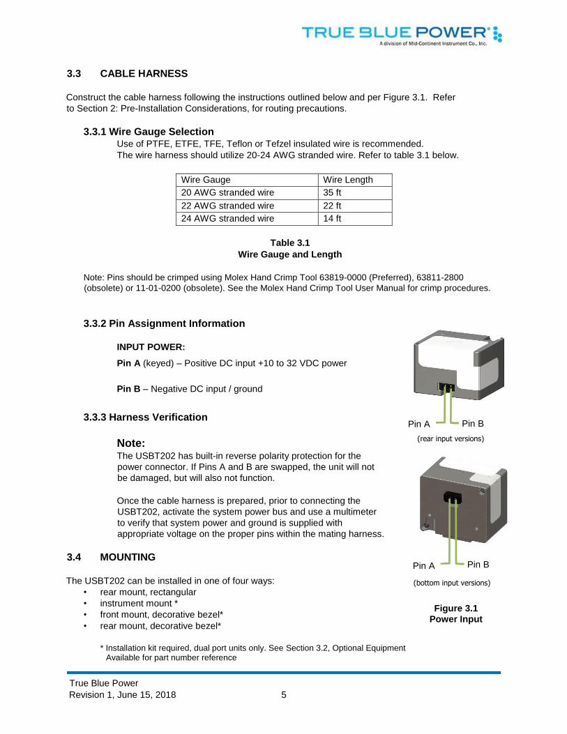
3.3.2 Pin Assignment Information INPUT POWER:
Pin A (keyed) – Positive DC input +10 to 32 VDC power
Pin B – Negative DC input / ground
3.3.3 Harness Verification
Note: The USBT202 has built-in reverse polarity protection for the
power connector. If Pins A and B are swapped, the unit will not
be damaged, but will also not function.
Once the cable harness is prepared, prior to connecting the
USBT202, activate the system power bus and use a multimeter
to verify that system power and ground is supplied with
appropriate voltage on the proper pins within the mating harness.
3.4 MOUNTING
The USBT202 can be installed in one of four ways:
• rear mount, rectangular
• instrument mount *
• front mount, decorative bezel*
• rear mount, decorative bezel*
* Installation kit required, dual port units only. See Section 3.2, Optional Equipment
Available for part number reference
Figure 3.1 Power Input
Pin B
( bottom input versions )
Pin A
Pin A
( rear input versions )
Pin B
True Blue Power
Revision 1, June 15, 2018 6
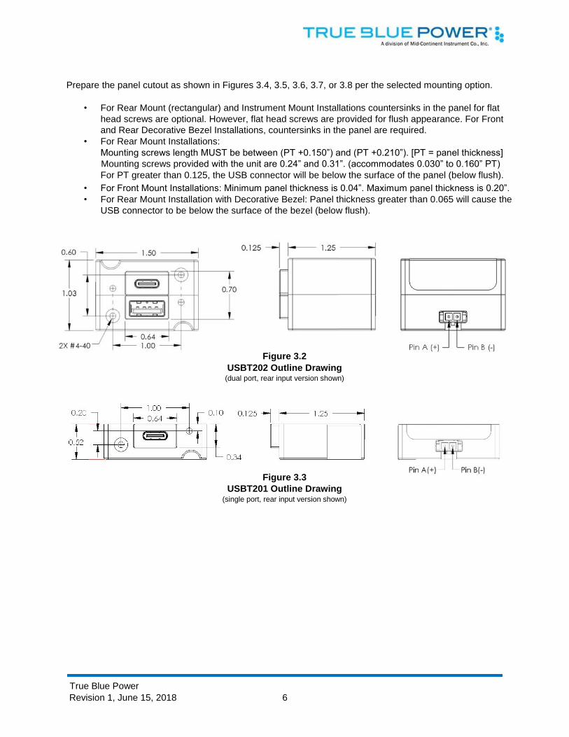
Prepare the panel cutout as shown in Figures 3.4, 3.5, 3.6, 3.7, or 3.8 per the selected mounting option.
• For Rear Mount (rectangular) and Instrument Mount Installations countersinks in the panel for flat
head screws are optional. However, flat head screws are provided for flush appearance. For Front
and Rear Decorative Bezel Installations, countersinks in the panel are required.
• For Rear Mount Installations:
Mounting screws length MUST be between (PT +0.150”) and (PT +0.210”). [PT = panel thickness]
Mounting screws provided with the unit are 0.24” and 0.31”. (accommodates 0.030” to 0.160” PT)
For PT greater than 0.125, the USB connector will be below the surface of the panel (below flush).
• For Front Mount Installations: Minimum panel thickness is 0.04”. Maximum panel thickness is 0.20”. • For Rear Mount Installation with Decorative Bezel: Panel thickness greater than 0.065 will cause the
USB connector to be below the surface of the bezel (below flush).
USBT202 Outline Drawing
(dual port, rear input version shown)
USBT201 Outline Drawing (single port, rear input version shown)
Figure 3.2
Figure 3.3
True Blue Power
Revision 1, June 15, 2018 7
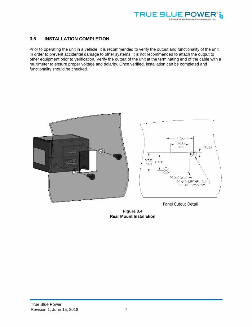
3.5 INSTALLATION COMPLETION
Prior to operating the unit in a vehicle, it is recommended to verify the output and functionality of the unit.
In order to prevent accidental damage to other systems, it is not recommended to attach the output to
other equipment prior to verification. Verify the output of the unit at the terminating end of the cable with a
multimeter to ensure proper voltage and polarity. Once verified, installation can be completed and
functionality should be checked.
Figure 3.4
Rear Mount Installation
Panel Cutout Detail

True Blue Power
Revision 1, June 15, 2018 8
Figure 3.5 Instrument Mount Installation
Step 1: install grommets
Step 2: place screw through mounting plate (x4) with front recess set to panel
thickness (see detail view)
Step 3: attach mounting plate to unit using screws included with unit
Step 4: place unit through panel cutout.
Tighten screws (x2)
Step 6: Peel adhesive backing, align pins on rear of cover plate into holes on mounting plate and press firmly
Step 5: Insert top and bottom screws
Ga p Set Detail
Step 1: attach adapte r plate to unit
Step 2: attach adapter plate to panel
Figure 3.6 Front Mount Installation
True Blue Power
Revision 1, June 15, 2018 9
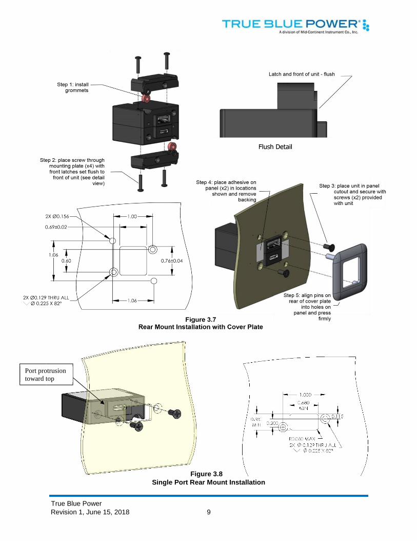
Single Port Rear Mount Installation
Port protrusion toward top
Figure 3.8
True Blue Power
Revision 1, June 15, 2018 10
SECTION 4 OPERATION
4.1 ELECTRICAL PERFORMANCE
The USBT202 Series High Power USB Charging Port converts a system’s (DC) input voltage within the
range specified to a 5V (DC) output. This output power is applied to a single or dual USB-A or USB-C
connector in accordance with the USB Implementers Forum.
The USB D+ and D- data lines communicate with the USB portable device to tell the device it is a
dedicated charging port (DCP), capable of a higher current than a standard USB port. This allows the
USB portable device to draw up to 3.0 Amps.
The unit is designed as a DC-to-DC converter with a series switch on each output to regulate current
applied to that output. Each series switch independently reduces the output current to a safe level if the
USB portable device draws excess current, is shorted or has a fault.
If the temperature of the USBT202 becomes elevated due to a fault or excessive load, the device will
seamlessly communicate with the USB portable device to lower the charge current. This allows the device
to continue charging while the unit returns to a temperature within designed limits. When the temperature
returns to a safe level the USBT202 will automatically reestablish the higher charge current level with the
device and continue charging.
4.2 PROTECTIVE FEATURES
4.2.1 Short Circuit Protection The USBT202 is capable of surviving a short circuit event without permanent damage. The
unit goes into an over-current condition so that the average current is significantly reduced
and the device is protected.
4.2.2 Over-Current Protection The USBT202 monitors the current draw individually on each port. During an over-current
condition the voltage is reduced. If the voltage falls below 3.8 VDC the output is turned off for
a period of 12 seconds. The output is then checked for continued over-current conditions
every 16 milliseconds. This condition is referred to as a hiccup mode. The device stays in this
mode until the over-current condition is removed, then returns to normal operation.
4.2.3 Low Input Voltage Shutdown If the input voltage applied to the USBT202 drops below 10 VDC the unit will shut down until
the applied voltage returns to a level within range.
4.2.4 Over-Temperature When the internal temperature of the USBT202 exceeds designed thresholds, the unit will
shut down and stop providing power. When the temperature returns to an acceptable level
the unit will automatically begin providing power as required, up to a full charge of 3.0 amps.