Embed Size (px)
Citation preview


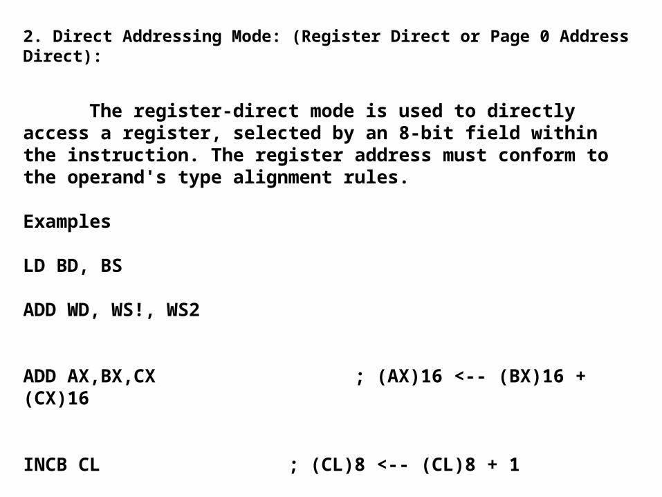
00H SFRs for IO Control
18H-19H SP
1AH-7FH AND 100H-AFFH Register File 232B and 256B additional RAM
0200H 1FFDH External Memory
1FFEH P3
1FFFH P4
2000H Lower Table of Interrupt Vectors
2014H Future Expansion Reserve
2018H Config Byte
Future Expansion Reserve
2020H-202FH Security Key ROM/EPROM
2030H-203FH Upper Table of Interrupt Vectors
2040H-205DH Peripheral transaction Server Vectors
Future Expansion Reserve
2080H ROM/EPROM Prog./Data Internal/Ext
6000H-0FFFFH External Prog/Data/IO Memory ROM/RAM

Initializing
CLR - Clear Word
CLRB - Clear Byte
CLRC - Clear Carry Flag
CLRVT - Clear Overflow Trap
SETC - Set Carry Flag

2.4.2 Data transfer
BMOVE - Block Move (80c196KB only)
LD - Load Word
LDB - Load Byte
LDBSE - Load Integer with Short-Integer
LDBZE - Load Word with Byte
ST - Store Word
STB - Store Byte

Stack operations
POP - Pop Word
POPA - Pop All (80c196KB only)
POPF - Pop Flags
PUSH - Push Word
PUSHA - Push All (80c196KB only)
PUSHF - Push Flags

Arithmetic operations
ADD - Add Words
ADDB - Add Bytes
ADDC - Add Words with Carry
ADDCB - Add Bytes with Carry
DEC - Decrement Word
DECB - Decrement Byte
DIV - Divide Integers (signed)
DIVB - Divide Short Integers (signed)
DIVU - Divide Words (unsigned)
DIVUB - Divide Bytes (unsigned)

EXT - Sign Extend Integer into Long-Integer
EXTB - Sign Extend Short-Integer into Integer
INC - Increment Word
INCB - Increment Byte
MUL - Multiply Integers (signed)
MULB - Multiply Short Integers (signed)
MULU - Multiply Words (unsigned
MULUB - Multiply Bytes (unsigned
NEG - Negate Integer

NEGB - Negate Short-Integer
NORML - Normalize Long-Integer
SUB - Subtract Words
SUBB - Subtract Bytes
SUBC - Subtract Words With Borrow
SUBCB - Subtract Words With Borrow

Logical operations
AND - Bitwise Logical AND Words
ANDB - Bitwise Logical AND Bytes
NOT - Complement Word
NOTB - Complement Byte
OR - Bitwise Logical OR Words
ORB - Bitwise Logical OR Bytes
XOR - Bitwise Logical XOR Words
XORB - Bitwise Logical XOR Bytes

Shifts
SHL - Left Shift Word
SHLB - Left Shift Byte
SHLL - Left Shift Double-Word
SHR - Logical Right Shift Word
SHRA - Arithmetic Right Shift Word
SHRAB - Arithmetic Right Shift Byte
SHRAL - Arithmetic Right Shift Double-Word
SHRB - Logical Right Shift Byte
SHRL - Logical Right Shift Double-Word

Comparisons
CMP - Compare Words
CMPB - Compare Bytes
CMPL - Compare Long (80c196KB only)

Unconditional jumps and calls
BR - Branch Indirect
LCALL - Long Call
LJMP - Long Jump
RET - Return from Subroutine
SCALL - Short Call
SJMP - Short Jump

Conditional jumps
DJNZ - Decrement and Jump if not Zero
DJNZW - Decrement and Jump if Not Zero Word (80c196KB only)
JBC - Jump if Bit Clear
JBS - Jump if Bit Set
JC - Jump if Carry
JE - Jump if Equal

JGE - Jump if Greater or Equal (signed)
JGT - Jump if Greater than (signed)
JH - Jump if Higher (unsigned)
JLE - Jump if Less or Equal (signed)
JLT - Jump if Less than (signed)
JNC - Jump if No Carry
JNE - Jump if Not Equal

JNH - Jump if Not Higher (unsigned)
JNST - Jump if No Sticky bit
JNV - Jump if No Overflow
JNVT - Jump if No Overflow Trap
JST - Jump if Sticky bit
JV - Jump if Overflow
JVT - Jump if Overflow Trap

Control
DI - Disable Interrupts
EI - Enable Interrupts
IDLPD - Idle / Powerdown (80c196KB only)
NOP - No Operation
RST - Reset System
SKIP - Two-byte NOP
TRAP - Software Trap


AX, BX, CX, DX are 16-bit registers.
AL, AH are the lower byte and the higher byte of AX respectively.
BL, BH are the lower byte and the higher byte of BX respectively.
CL, CH are the lower byte and the higher byte of CX respectively.
DL, DH are the lower byte and the higher byte of DX respectively.
These are the same as the names for the general data registers used in the 8086.
It is important to understand that in the 80c196 these are not dedicated registers, but merely the symbolic name assigned by the programmer to four words within the on-chip 232 general registers.
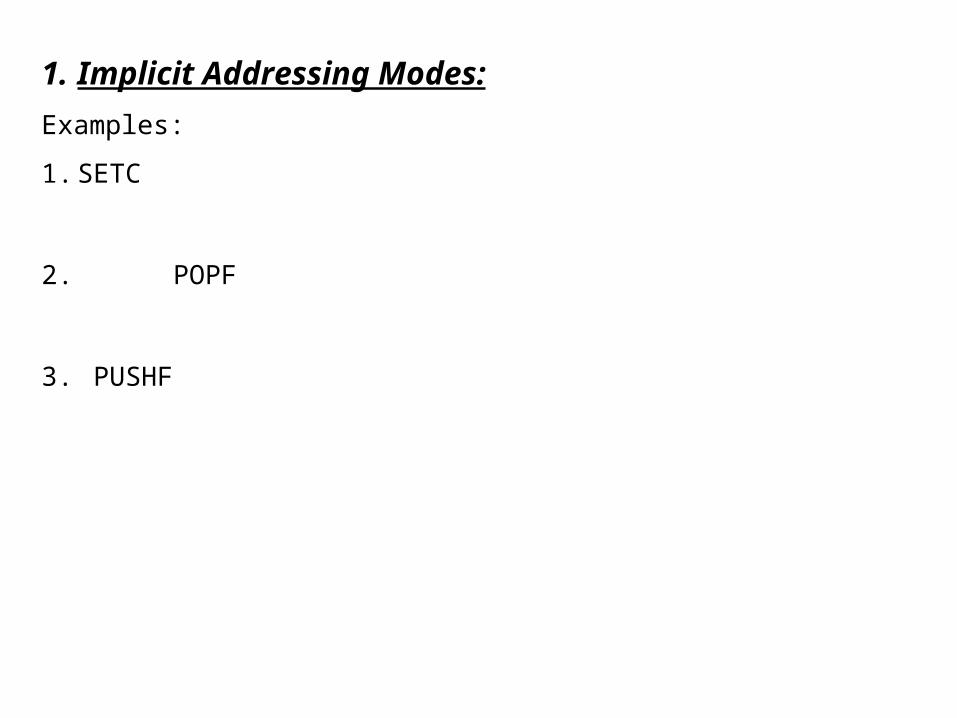
1. Implicit Addressing Modes:
Examples:
1. SETC
2. POPF
3. PUSHF
2. Direct Addressing Mode: (Register Direct or Page 0 Address Direct):
The register-direct mode is used to directly access a register, selected by an 8-bit field within the instruction. The register address must conform to the operand's type alignment rules. Examples
LD BD, BS
ADD WD, WS!, WS2
ADD AX,BX,CX ; (AX)16 <-- (BX)16 + (CX)16
INCB CL ; (CL)8 <-- (CL)8 + 1

3. Immediate Addressing Mode:
This addressing mode allows an operand to taken directly from a field in the instruction. For operations on bytes this field is 8-bit wide, for operations on words it is 16-bit wide.
Examples:
LD WD, #3000H
ADD WD, WS1, #data16
ADD WD, #data16
ADD AX,#340 ; (AX)16 <-- (AX)16 + 340
PUSH #1234H ; (SP)16 <-- (SP)16 - 2
; ((SP)16)16 <-- 1234H
DIVB AX,#10 ; (AL)8 <-- (AX)16 / 10
; (AH)8 <-- (AX)16 % 10

4. Indirect Addressing Modes:
a) Without auto post increment of the pointer
Examples:
ADD WD, WS1, [WS2]
LD BX,[AX]
; (BX)16 <-- ((AX)16)16
ADDB AL,BL,[CX]
; (AL)8 <-- (BL)8 + ((CX)16)8
POP [AX]
; ((AX)16)16 <-- ((SP)16)16
; (SP)16 <-- (SP)16 + 2

With auto post increment of the pointer,Examples:ADD WD, WS1, [WS2]+
LD AX,[BX]+ ; (AX)16 <-- ((BX)16)16 ; (BX)16 <-- (BX)16 + 2
ADDB AL,BL,[CX]+ ; (AL)8 <-- (BL)8 + ((CX)16)8 ; (CX)16 <-- (CX)16 + 2
PUSH [AX]+ ; (SP)16 <-- (SP)16 - 2 ; ((SP)16)16 <-- ((AX)16)16 ; (AX)16 <-- (AX)16 + 2

C) Indexed short In this addressing mode an 8-bit field in the instruction selects a word register which contains an address.
A second 8-bit field in the instruction stream (displacement) is sign-extended and summed with the register value to form the address of the operand.
Since the displacement is sign-extended, the effective address can be up to 128 bytes before the address in the register, or up to 127 bytes after it.
Examples LD AX,12[BX] ; (AX)16 <-- ((BX)16 + 12)16
MULB AX,BL,3[CX] ; (AX)16 <-- (BL)8 * ((CX)16 + 3)8

D) Indexed long
This addressing mode is like short indexed addressing except that the displacement is a 16-bit field taken from the instruction stream to form the address of the operand. No sign extension is necessary.
Examples AND AX,BX,TABLE[CX]
; (AX)16 <-- (BX)16 . (TABLE16 + (CX)16)16
ST AX,TABLE[BX] ; (AX)16 <-- (TABLE16 + (BX)16)16
ADDB AL,BL,TABLE[CX] ; (AL)8 <-- (BL)8 + (TABLE16 + (CX)16)8


Examples:
1. ST XD, YS
2. LD
3. PUSH
4. POP


Examples:
1.CLRB XD
2.CLRW XD
3.CLRLD XD
A byte or word can be extended to a word or a long word by sign bit extension.
Examples:
1.EXTB XD
2. EXTW XD

Similarly, normalization of a byte into a word or a long word or a word into a long word can also be done.
Normalization is simply putting 0s at the higher bytes.
Logical Operations:
1. NOTB XD
2. NOTW XD
3. NOTLD XD

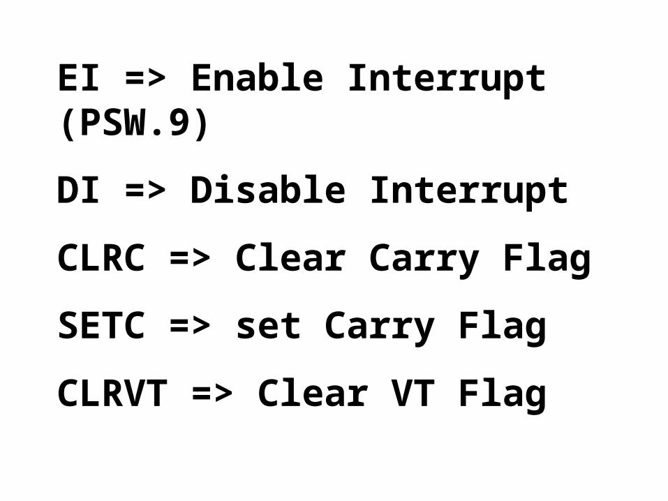
EI => Enable Interrupt (PSW.9)
DI => Disable Interrupt
CLRC => Clear Carry Flag
SETC => set Carry Flag
CLRVT => Clear VT Flag


V :
The oVerflow flag is set to indicate that the operation generated a result which is outside the range for the destination data type. For the left shift operations the V flag will be set if the most significant bit changes at any time during the shift.
VT :
The oVerflow Trap flag is set when the V flag is set, but is only cleared by the CLRVT, JVT and JNVT instructions. The operation of the VT flag allows testing for a possible overflow condition at the end of a sequence of related arithmetic operations. This is generally more efficient than testing the VT flag after each instruction.

C : The Carry flag is set to indicate the state of the arithmetic carry from the most significant bit of the ALU for arithmetic operations, or the state of the last bit shifted out of an operand for shift operations. Arithmetic borrow after a subtract operation is the complement of the C flag (i.e. if the operation generated a borrow the C flag is cleared). X : Reserved. Should always be cleared when writing to the PSW (cf. POPF instruction). I : The global Interrupt disable bit disables all interrupts except NMI when cleared.

Z : The Zero flag is set to indicate that the operation generated a result equal to zero. For the add-with-carry (ADDC) and subtract-with-borrow (SUBB) operations the Z flag is cleared if the result is not zero, but is never set. These two instructions are normally used on conjunction with the ADD and SUB instructions to perform multiple precision arithmetic. Theoperation of the Z flag for these operations leaves it indicating the proper result for the entire multiple precision calculation.
N : The Negative flag is set to indicate that the operation generated a negative result. The N flag will be in the algebraically correct state even if an overflow occurs. For shift operations the N flag will be set to the same value as the most significant bit of the result. This is true even if the shift count is 0.

ST :
The STicky bit flag is set to indicate that during a shift a 1 has first been shifted into the C flag, and then shifted out.
The ST flag is undefined after a multiply operation. The ST flag can be used along with the C flag to control rounding after a right shift.
Consider multiplying to 8-bit quantities and then scaling the result down to 12 bits :
MULUB AX,CL,DL ; AX <-- CL*DL
SHR AX,#4 ; shift right 4 places
If the C flag is set after the shift, it indicates that the bits shifted off the end of the operand were greater-than or equal-to half the LSB of the result. Without the ST flag, the rounding decision must be made on the basis of the C flag alone.
![Untitled Document [] · CS4299 3 4.10 Stereo Analog Mixer Input Gain Registers (Index 10h - 18h) .....24 4.11 Input Mux Select Register (Index 1Ah) .....25](https://img.pdfslide.us/doc/110x75/5acee6f77f8b9a8b1e8c0c5d/untitled-document-3-410-stereo-analog-mixer-input-gain-registers-index-10h.jpg)


![AT25128B and AT25256B · AT25128B/256B [DATASHEET] 3 Atmel-8698E-SEEPROM-AT25128B-256B-Datasheet_012015 3. Block Diagram Figure 3-1. Block Diagram Memory Array 16,384/32,768 x 8 Status](https://img.pdfslide.us/doc/110x75/609cce59f0b0c86cf830d03c/at25128b-and-at25256b-at25128b256b-datasheet-3-atmel-8698e-seeprom-at25128b-256b-datasheet012015.jpg)


![281—41.1(256B,34CFR300)Purposes.SPECIALEDUCATION...Ch41,p.2 Education[281] IAC12/16/09 281—41.6(256B,34CFR300)Assistivetechnologyservice. “Assistivetechnologyservice”meansany](https://img.pdfslide.us/doc/110x75/5f2a5134e0779a238004e309/281a411256b34cfr300-ch41p2-education281-iac121609-281a416256b34cfr300assistivetechnologyservice.jpg)