Embed Size (px)
Citation preview
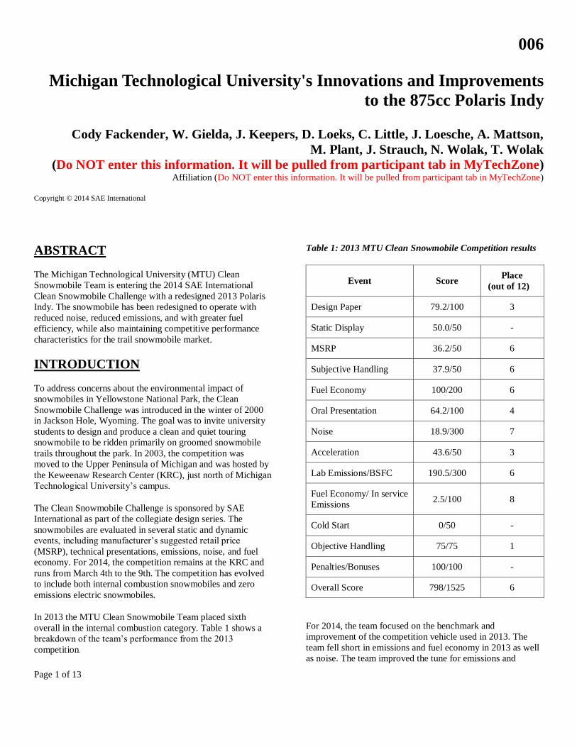
Page 1 of 13
006
Michigan Technological University's Innovations and Improvements
to the 875cc Polaris Indy
Cody Fackender, W. Gielda, J. Keepers, D. Loeks, C. Little, J. Loesche, A. Mattson,
M. Plant, J. Strauch, N. Wolak, T. Wolak
(Do NOT enter this information. It will be pulled from participant tab in MyTechZone)
Affiliation (Do NOT enter this information. It will be pulled from participant tab in MyTechZone)
Copyright © 2014 SAE International
ABSTRACT
The Michigan Technological University (MTU) Clean
Snowmobile Team is entering the 2014 SAE International
Clean Snowmobile Challenge with a redesigned 2013 Polaris
Indy. The snowmobile has been redesigned to operate with
reduced noise, reduced emissions, and with greater fuel
efficiency, while also maintaining competitive performance
characteristics for the trail snowmobile market.
INTRODUCTION
To address concerns about the environmental impact of
snowmobiles in Yellowstone National Park, the Clean
Snowmobile Challenge was introduced in the winter of 2000
in Jackson Hole, Wyoming. The goal was to invite university
students to design and produce a clean and quiet touring
snowmobile to be ridden primarily on groomed snowmobile
trails throughout the park. In 2003, the competition was
moved to the Upper Peninsula of Michigan and was hosted by
the Keweenaw Research Center (KRC), just north of Michigan
Technological University’s campus.
The Clean Snowmobile Challenge is sponsored by SAE
International as part of the collegiate design series. The
snowmobiles are evaluated in several static and dynamic
events, including manufacturer’s suggested retail price
(MSRP), technical presentations, emissions, noise, and fuel
economy. For 2014, the competition remains at the KRC and
runs from March 4th to the 9th. The competition has evolved
to include both internal combustion snowmobiles and zero
emissions electric snowmobiles.
In 2013 the MTU Clean Snowmobile Team placed sixth
overall in the internal combustion category. Table 1 shows a
breakdown of the team’s performance from the 2013
competition.
Table 1: 2013 MTU Clean Snowmobile Competition results
Event Score Place
(out of 12)
Design Paper 79.2/100 3
Static Display 50.0/50 -
MSRP 36.2/50 6
Subjective Handling 37.9/50 6
Fuel Economy 100/200 6
Oral Presentation 64.2/100 4
Noise 18.9/300 7
Acceleration 43.6/50 3
Lab Emissions/BSFC 190.5/300 6
Fuel Economy/ In service
Emissions 2.5/100 8
Cold Start 0/50 -
Objective Handling 75/75 1
Penalties/Bonuses 100/100 -
Overall Score 798/1525 6
For 2014, the team focused on the benchmark and
improvement of the competition vehicle used in 2013. The
team fell short in emissions and fuel economy in 2013 as well
as noise. The team improved the tune for emissions and
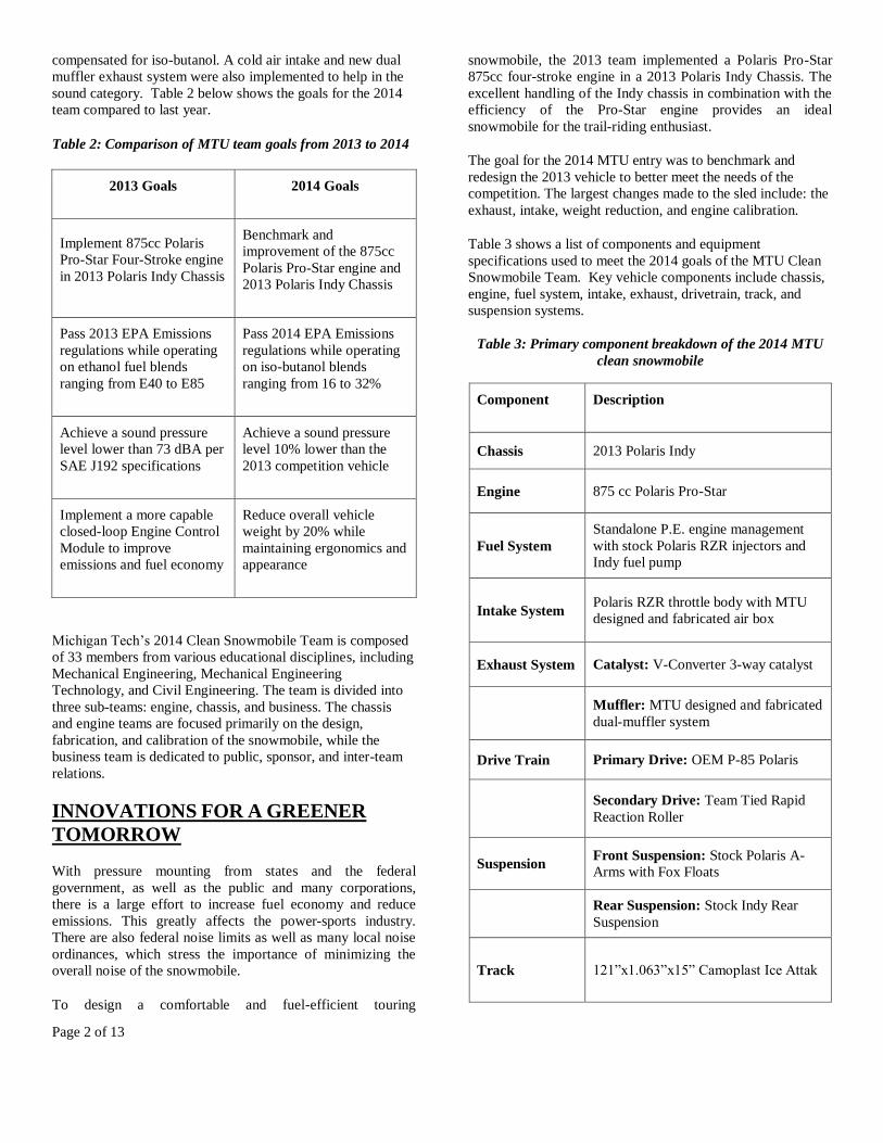
Page 2 of 13
compensated for iso-butanol. A cold air intake and new dual
muffler exhaust system were also implemented to help in the
sound category. Table 2 below shows the goals for the 2014
team compared to last year.
Table 2: Comparison of MTU team goals from 2013 to 2014
2013 Goals 2014 Goals
Implement 875cc Polaris
Pro-Star Four-Stroke engine
in 2013 Polaris Indy Chassis
Benchmark and
improvement of the 875cc
Polaris Pro-Star engine and
2013 Polaris Indy Chassis
Pass 2013 EPA Emissions
regulations while operating
on ethanol fuel blends
ranging from E40 to E85
Pass 2014 EPA Emissions
regulations while operating
on iso-butanol blends
ranging from 16 to 32%
Achieve a sound pressure
level lower than 73 dBA per
SAE J192 specifications
Achieve a sound pressure
level 10% lower than the
2013 competition vehicle
Implement a more capable
closed-loop Engine Control
Module to improve
emissions and fuel economy
Reduce overall vehicle
weight by 20% while
maintaining ergonomics and
appearance
Michigan Tech’s 2014 Clean Snowmobile Team is composed
of 33 members from various educational disciplines, including
Mechanical Engineering, Mechanical Engineering
Technology, and Civil Engineering. The team is divided into
three sub-teams: engine, chassis, and business. The chassis
and engine teams are focused primarily on the design,
fabrication, and calibration of the snowmobile, while the
business team is dedicated to public, sponsor, and inter-team
relations.
INNOVATIONS FOR A GREENER
TOMORROW
With pressure mounting from states and the federal
government, as well as the public and many corporations,
there is a large effort to increase fuel economy and reduce
emissions. This greatly affects the power-sports industry.
There are also federal noise limits as well as many local noise
ordinances, which stress the importance of minimizing the
overall noise of the snowmobile.
To design a comfortable and fuel-efficient touring
snowmobile, the 2013 team implemented a Polaris Pro-Star
875cc four-stroke engine in a 2013 Polaris Indy Chassis. The
excellent handling of the Indy chassis in combination with the
efficiency of the Pro-Star engine provides an ideal
snowmobile for the trail-riding enthusiast.
The goal for the 2014 MTU entry was to benchmark and
redesign the 2013 vehicle to better meet the needs of the
competition. The largest changes made to the sled include: the
exhaust, intake, weight reduction, and engine calibration.
Table 3 shows a list of components and equipment
specifications used to meet the 2014 goals of the MTU Clean
Snowmobile Team. Key vehicle components include chassis,
engine, fuel system, intake, exhaust, drivetrain, track, and
suspension systems.
Table 3: Primary component breakdown of the 2014 MTU
clean snowmobile
Component Description
Chassis 2013 Polaris Indy
Engine 875 cc Polaris Pro-Star
Fuel System
Standalone P.E. engine management
with stock Polaris RZR injectors and
Indy fuel pump
Intake System Polaris RZR throttle body with MTU
designed and fabricated air box
Exhaust System Catalyst: V-Converter 3-way catalyst
Muffler: MTU designed and fabricated
dual-muffler system
Drive Train Primary Drive: OEM P-85 Polaris
Secondary Drive: Team Tied Rapid
Reaction Roller
Suspension Front Suspension: Stock Polaris A-
Arms with Fox Floats
Rear Suspension: Stock Indy Rear
Suspension
Track 121”x1.063”x15” Camoplast Ice Attak
Page 3 of 13
ENGINE
For the 2014 competition, the MTU Clean Snowmobile Team
decided to keep the same Polaris Pro-Star 875cc Dual
Overhead Cam (DOHC) four-stroke engine that was ran in
2013. This engine proved to be very reliable and tolerant to
the wide range of ethanol blends tested during the 2013
competition. Equipped with the Performance Electronics
ECU, a new dual exhaust muffler system, and intake; the team
was able to calibrate the Pro-Star engine in order to achieve
better marks at the 2014 Clean Snowmobile Competition.
PERFORMANCE ELECTRONICS
The 2014 competition snowmobile utilizes a PE3-8400A
Engine Control Unit (ECU) from Performance Electronics
Ltd. The compact size and light weight of the stand-alone
control unit allowed for easy mounting into the Indy chassis.
The control unit manipulates fuel and ignition needs for the
engine, based on different operating conditions. Using the
controller, modifications can be made to the fuel flow and
ignition timing of the engine as well as numerous other engine
parameters to optimize performance and fuel efficiency. In
addition, the control unit allowed for real-time tuning of the
engine with on-board data logging of engine parameters and
external inputs. Performance Electronics also supports
wireless tuning, which allowed for the MTU Clean
Snowmobile Team to operate the snowmobile at a wide range
of in-service testing modes while adjusting the timing and
injection parameters remotely. Utilizing the tuning capabilities
of the ECU, the team was able to optimize the capabilities of
the Pro-Star 875cc engine.
A cam position sensor was added this year to change the
engine from batch injection to sequential injection. Currently
the engine would inject fuel and spark in both cylinders when
each cylinder reached TDC. This results in over-fueling of the
cylinders causing inefficiencies as raw fuel was blown directly
out of the exhaust. This is inefficient for fuel mileage as well
as undesirable for emissions. The flywheel is set up to have 36
teeth minus 1. This gap is picked up by a crank position
sensor. In batch injection, fuel is added according to the gap
every time it is seen because the ECU doesn't know which is
the compression stroke and which is the exhaust stroke. With
the addition of the cam position sensor and sequential
injection the compression stroke is known resulting in less
over fueling, resulting in improved emissions as well as fuel
economy.
CALIBRATION TECHNIQUES
The Michigan Technological University Clean Snowmobile
Team divided the base fuel and ignition tables into zones as a
means for applying criteria to different engine operating
conditions. Zone 1 correlated to the idle region of the engines
base tables. The commanded fuel was determined while
targeting lambda of 1.00. This was created for both emissions
output and fuel consumption. Great care was taken to ensure
proper engine operation within this zone. Due to a lack of idle
control, the idle speed was maintained by the force balance
between the friction of the engine and the torque output
created by combustion. Zone 2 contains the tip-in portion of
engine operation. The tip-in portion in this case was the event
when the primary clutch engaged the drive belt. The delivered
fuel was still a function of the target lambda value of 1.00.
The ignition advance was set to maximum brake torque
(MBT) timing to account for the clutch engagement. Zone 3
can be described as the cruise region of the base tables. This
region contains the speed-load points that the competition
vehicle would experience during the Endurance Run. In
contrast to an automobile, snowmobiles experience greater
engine loads during cruising due to the added drag forces
created by the skis and rotating track. MBT timing was used to
extract the maximum amount of energy from each combustion
event. This allowed for an increase in mechanical efficiency
during this relatively light-load engine operation. Zone 4
contains the area of the tables that are related to a slight
acceleration event. The throttle blade in this case would not be
completely open, but moderately open. The lambda value of
1.00 was still targeted due to Zone 4 not being a wide open
throttle (WOT) condition. MBT timing was still utilized to
extract as much energy from the air-fuel mixture as possible.
Zone 5 is the region of high engine speeds and relatively low
engine loads. The engine does not spend much time in this
region, but will pass through Zone 5 after a throttle-chop.
Delivered fuel still pursued the lambda value of 1.00 and
ignition values the team set high enough, in order to protect
exhaust components. Ignition advance values of 35deg Before
Top Dead Center (BTDC) and 45deg BTDC were commonly
used on Zone 5. These ignition advance values released the
heat of combustion into the cylinder walls instead of the
exhaust valves and catalyst. Zone 6 was treated as the WOT
portion of the base tables. The intent when operating an engine
within Zone 6 is maximum power production. Some fueling
enrichment was used to better guarantee the reaction of the
oxygen molecules within the intake charge resulting in a more
complete burn. The ignition advance values were kept a
significant distance away from the knock limit. Zone 7
contains low manifold pressures typically associated with
engine braking. The continuously-variable transmission
(CVT) on a snowmobile does not let the engine experience
extreme engine braking conditions. This provides for a rather
small region that the engine passes through very briefly. The
light-load allows for a target lambda value of 1.00 to be
pursued as well as moderate ignition advance values. The
ignition advance values in this zone are very similar of those
occurring in Zone 3.
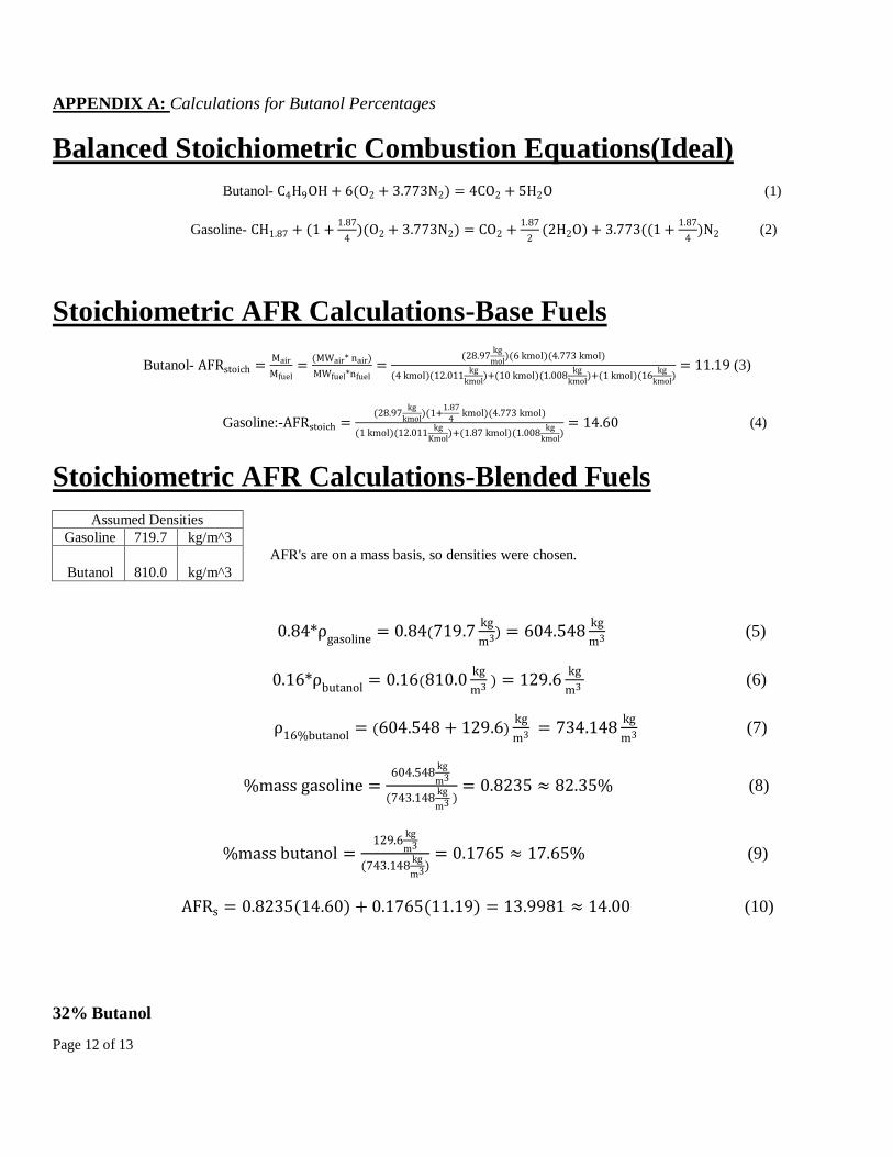
FLEX-FUEL IMPLEMENTATION
As per the 2014 Clean Snowmobile Challenge rules, each
competition vehicle must have the capacity to operate on corn-
based bio-isobutanol fuel. The flex fuel range for the 2014
competition is 16% to 32% iso-butanol content. The
Michigan Technological University Clean Snowmobile Team
Page 4 of 13
performed calculations to determine the stoichiometric air-fuel
ratio (AFR) of each iso-butanol blended fuel.
To do this the team used the latent heating value
(LHV)(MJ/kg), stoichiometric values, and fuel
densities(kg/m^3) . The values obtained allowed the team to
calculate the mass of oxygen and the measured iso-butanol
content for this year's competition and equate them to the
equivalent percentage of ethanol. The team also formed
calculations that would allow the team to compute what the
stoichiometric values were for different percentages of iso-
butanol. The calculations for the iso-butanol, gasoline, and
iso-butanol blended fuels can be reviewed in Appendix A.
The high cost associated with iso-butanol fuel pushed the team
to use ethanol-based equivalents during engine calibration
development. It was determined that a 16% iso-butanol blend
corresponded to a 10% ethanol blend based and a 32% iso-
butanol blend was equivalent to a 21% ethanol blend, both of
these calculated values are based on the mass of oxygen in
both E10 and E21. The base fuel table was created for engine
operation on gasoline with an octane rating of 91. The alcohol
content within the competition fuel was accounted for through
the means of an alcohol content analyzer. The commanded
fuel injector pulse-width included a positive adder that
accounted for the required increase in fueling due to the
alcohol content. The magnitude of the positive adder changed
relative to the alcohol content detected by the alcohol content
analyzer. For example, the positive adder associated a 32%
iso-butanol blend would be greater than that for a 16% iso-
butanol blend. While the majority of the positive adder fuel
trim was developed based on ethanol-blended fuels, iso-
butanol was later tested to verify proper engine operation.
IGNITION TUNING
To help with dynamometer tuning, the team implemented a
cylinder pressure transducer utilizing a spark plug style pick-
up made by PCB Piezotronics Inc. as shown in Figure 1.
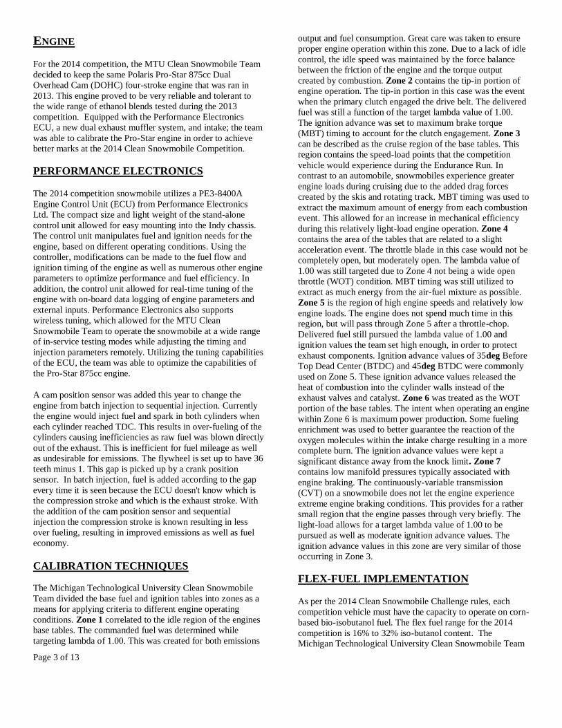
Figure 1: PCB pressure transducer
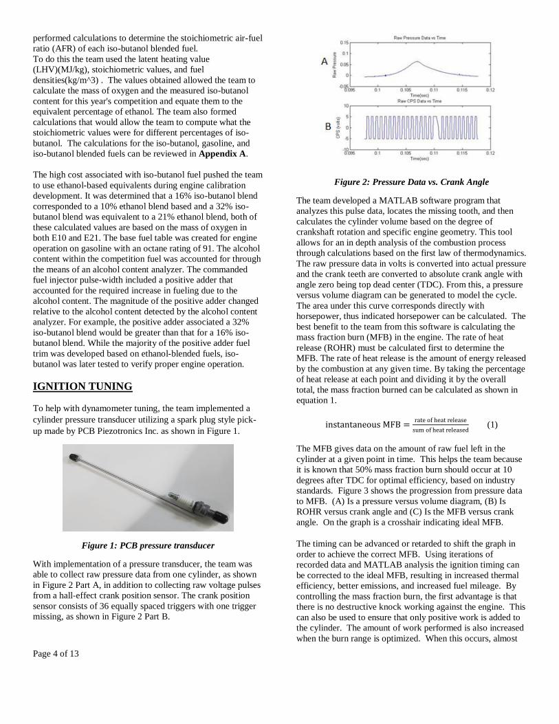
With implementation of a pressure transducer, the team was
able to collect raw pressure data from one cylinder, as shown
in Figure 2 Part A, in addition to collecting raw voltage pulses
from a hall-effect crank position sensor. The crank position
sensor consists of 36 equally spaced triggers with one trigger
missing, as shown in Figure 2 Part B.
Figure 2: Pressure Data vs. Crank Angle
The team developed a MATLAB software program that
analyzes this pulse data, locates the missing tooth, and then
calculates the cylinder volume based on the degree of
crankshaft rotation and specific engine geometry. This tool
allows for an in depth analysis of the combustion process
through calculations based on the first law of thermodynamics.
The raw pressure data in volts is converted into actual pressure
and the crank teeth are converted to absolute crank angle with
angle zero being top dead center (TDC). From this, a pressure
versus volume diagram can be generated to model the cycle.
The area under this curve corresponds directly with
horsepower, thus indicated horsepower can be calculated. The
best benefit to the team from this software is calculating the
mass fraction burn (MFB) in the engine. The rate of heat
release (ROHR) must be calculated first to determine the
MFB. The rate of heat release is the amount of energy released
by the combustion at any given time. By taking the percentage
of heat release at each point and dividing it by the overall
total, the mass fraction burned can be calculated as shown in
equation 1.
(1)
The MFB gives data on the amount of raw fuel left in the
cylinder at a given point in time. This helps the team because
it is known that 50% mass fraction burn should occur at 10
degrees after TDC for optimal efficiency, based on industry
standards. Figure 3 shows the progression from pressure data
to MFB. (A) Is a pressure versus volume diagram, (B) Is
ROHR versus crank angle and (C) Is the MFB versus crank
angle. On the graph is a crosshair indicating ideal MFB.
The timing can be advanced or retarded to shift the graph in
order to achieve the correct MFB. Using iterations of
recorded data and MATLAB analysis the ignition timing can
be corrected to the ideal MFB, resulting in increased thermal
efficiency, better emissions, and increased fuel mileage. By
controlling the mass fraction burn, the first advantage is that
there is no destructive knock working against the engine. This
can also be used to ensure that only positive work is added to
the cylinder. The amount of work performed is also increased
when the burn range is optimized. When this occurs, almost
Page 5 of 13
all of the fuel energy is being extracted by completing
combustion of all the fuel in the cylinder. This also means
that emission outputs are greatly decreased, as there are low
levels of unburned fuel leaving the cylinder.
Figure 3: Pressure Data to Mass Fraction Burn
INTAINTAKE MODIFICATION
Figure 4: Volumetric flow rate graph
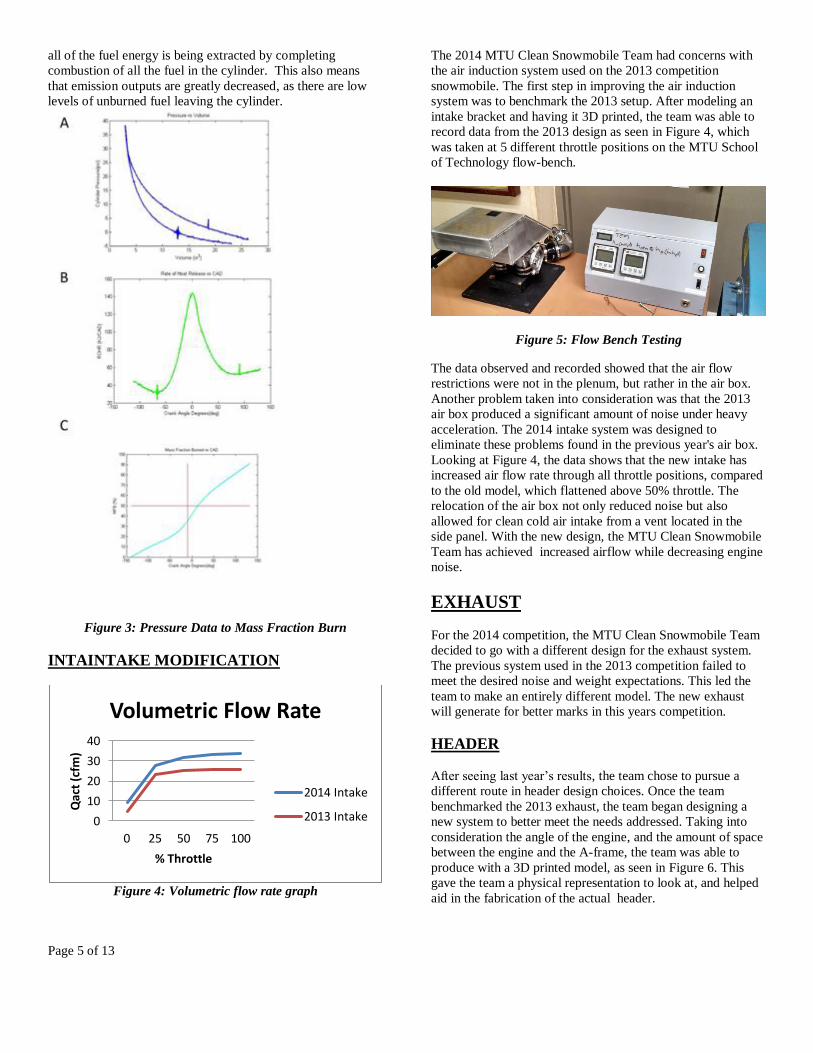
The 2014 MTU Clean Snowmobile Team had concerns with
the air induction system used on the 2013 competition
snowmobile. The first step in improving the air induction
system was to benchmark the 2013 setup. After modeling an
intake bracket and having it 3D printed, the team was able to
record data from the 2013 design as seen in Figure 4, which
was taken at 5 different throttle positions on the MTU School
of Technology flow-bench.
Figure 5: Flow Bench Testing
The data observed and recorded showed that the air flow
restrictions were not in the plenum, but rather in the air box.
Another problem taken into consideration was that the 2013
air box produced a significant amount of noise under heavy
acceleration. The 2014 intake system was designed to
eliminate these problems found in the previous year's air box.
Looking at Figure 4, the data shows that the new intake has
increased air flow rate through all throttle positions, compared
to the old model, which flattened above 50% throttle. The
relocation of the air box not only reduced noise but also
allowed for clean cold air intake from a vent located in the
side panel. With the new design, the MTU Clean Snowmobile
Team has achieved increased airflow while decreasing engine
noise.
EXHAUST
For the 2014 competition, the MTU Clean Snowmobile Team
decided to go with a different design for the exhaust system.
The previous system used in the 2013 competition failed to
meet the desired noise and weight expectations. This led the
team to make an entirely different model. The new exhaust
will generate for better marks in this years competition.
HEADER
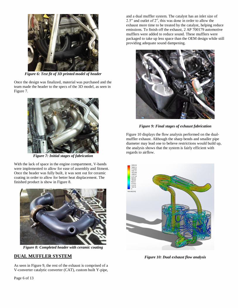
After seeing last year’s results, the team chose to pursue a
different route in header design choices. Once the team
benchmarked the 2013 exhaust, the team began designing a
new system to better meet the needs addressed. Taking into
consideration the angle of the engine, and the amount of space
between the engine and the A-frame, the team was able to
produce with a 3D printed model, as seen in Figure 6. This
gave the team a physical representation to look at, and helped
aid in the fabrication of the actual header.
0
10
20
30
40
0 25 50 75 100
Qac
t (c
fm)
% Throttle
Volumetric Flow Rate
2014 Intake
2013 Intake
Page 6 of 13
Figure 6: Test fit of 3D printed model of header
Once the design was finalized, material was purchased and the
team made the header to the specs of the 3D model, as seen in
Figure 7.
Figure 7: Initial stages of fabrication
With the lack of space in the engine compartment, V-bands
were implemented to allow for ease of assembly and fitment.
Once the header was fully built, it was sent out for ceramic
coating in order to allow for better heat displacement. The
finished product is show in Figure 8.
Figure 8: Completed header with ceramic coating
DUAL MUFFLER SYSTEM
As seen in Figure 9, the rest of the exhaust is comprised of a
V-converter catalytic converter (CAT), custom built Y-pipe,
and a dual muffler system. The catalyst has an inlet size of
2.5” and outlet of 2”, this was done in order to allow the
exhaust more time to be treated by the catalyst, helping reduce
emissions. To finish off the exhaust, 2 AP 700179 automotive
mufflers were added to reduce sound. These mufflers were
packaged to take up less space than the OEM design while still
providing adequate sound dampening.
Figure 9: Final stages of exhaust fabrication
Figure 10 displays the flow analysis performed on the dual-
muffler exhaust. Although the sharp bends and smaller pipe
diameter may lead one to believe restrictions would build up,
the analysis shows that the system is fairly efficient with
regards to airflow.
Figure 10: Dual exhaust flow analysis
Page 7 of 13
CHASSIS
The 2014 MTU Clean Snowmobile Team chassis is a
modified 2013 Polaris Indy. This is the same chassis set up
that was used for the 2013 vehicle. For the 2014 competition,
the team benchmarked and improved upon the design. The
chassis offers several important advantages over other
available chassis in the industry, including weight reduction
and improved rider ergonomics. The Indy also uses a similar
platform to the Switchback and Rush models, which allowed
for previous knowledge to be utilized. While the snowmobile
uses the same Pro-Ride chassis as higher-end snowmobiles, it
also offers a consumer friendly MSRP of $11697.58.
VIBRATION ANALYSIS
Noise accounts for two events totaling 300 points in
competition. Snowmobiles have considerable amounts of
vibrations, mainly caused by the engine and its air flow. Work
has been done to eliminate noise caused by vibrations from the
exhaust and intake, leaving the chassis as the next source to
address. A vibration analysis was conducted on the rolling
chassis of the snowmobile in order to determine which areas
needed to be addressed. Noise is created by the snowmobile
because of the fiberglass rods and metal clips in the track
impacting the bogey wheels and suspension rails as it rotates.
This impact force causes vibrations which results in a
significant amount of noise produced. The way to reduce the
noise is to cancel out the vibrations before they get to the
tunnel. This can be done at different points throughout the
chassis, including the bogey wheels, suspension components,
and the mounting of the skid to the tunnel. The team decided
to evaluate how different bogey wheel designs and
orientations affected vibrations.
The chassis team decided to do tests pulling the sled as this
would eliminate the noise created by a running motor. The
tests were conducted by pulling the snowmobile behind a
vehicle at 35 miles per hour, as this is the upper limit of noise
testing in SAE standard J192 used for Competition.
Accelerometers were placed at various points on the sled,
including the rails of the skid, foot well near the mounting
bolts for the skid, and on the seat. Sound level was measured
for each run, as well at a distance of 20 feet. Three different
wheel orientations were tested. This was done because it can
be controlled which bogey wheels hit the track rods at the
same time. Stock/symmetric, left staggered from the right,
and front staggered from the rear were all tested to determine
the best orientation. Four different wheel designs were also
tested. Two different sets of stock wheels were tested along
with two custom designs. FEA was used to ensure that the
two custom designs were at stress levels below the shear
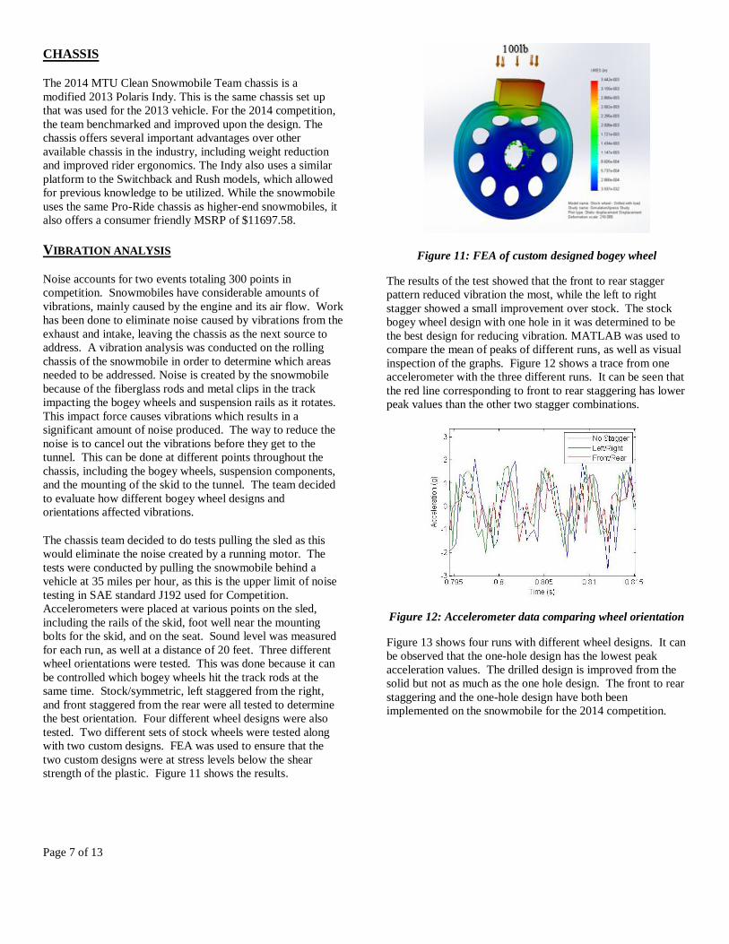
strength of the plastic. Figure 11 shows the results.
Figure 11: FEA of custom designed bogey wheel
The results of the test showed that the front to rear stagger
pattern reduced vibration the most, while the left to right
stagger showed a small improvement over stock. The stock
bogey wheel design with one hole in it was determined to be
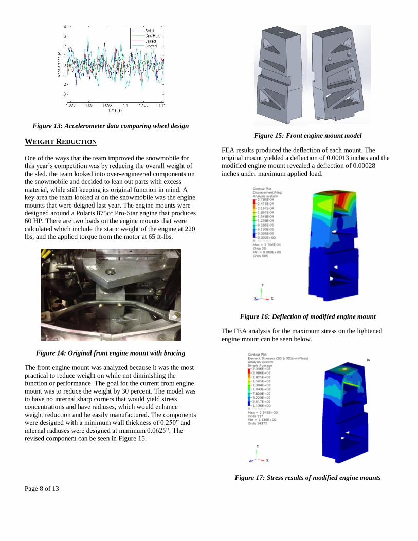
the best design for reducing vibration. MATLAB was used to
compare the mean of peaks of different runs, as well as visual
inspection of the graphs. Figure 12 shows a trace from one
accelerometer with the three different runs. It can be seen that
the red line corresponding to front to rear staggering has lower
peak values than the other two stagger combinations.
Figure 12: Accelerometer data comparing wheel orientation
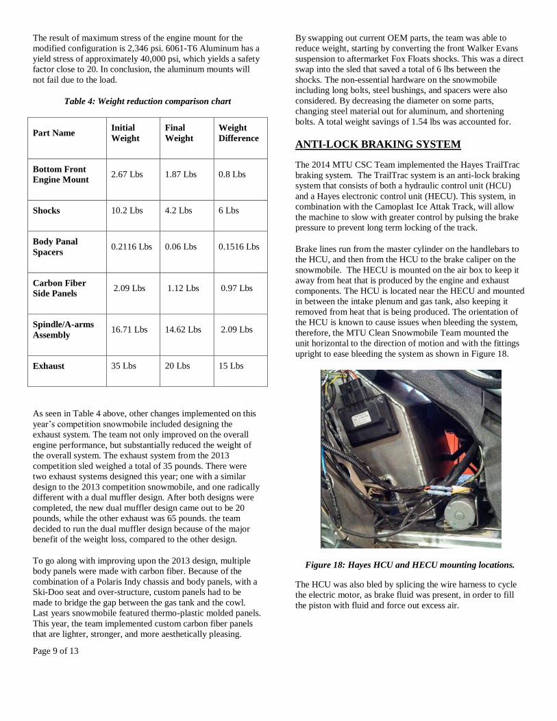
Figure 13 shows four runs with different wheel designs. It can
be observed that the one-hole design has the lowest peak
acceleration values. The drilled design is improved from the
solid but not as much as the one hole design. The front to rear
staggering and the one-hole design have both been
implemented on the snowmobile for the 2014 competition.
Page 8 of 13
Figure 13: Accelerometer data comparing wheel design
WEIGHT REDUCTION
One of the ways that the team improved the snowmobile for
this year’s competition was by reducing the overall weight of
the sled. the team looked into over-engineered components on
the snowmobile and decided to lean out parts with excess
material, while still keeping its original function in mind. A
key area the team looked at on the snowmobile was the engine
mounts that were deigned last year. The engine mounts were
designed around a Polaris 875cc Pro-Star engine that produces
60 HP. There are two loads on the engine mounts that were
calculated which include the static weight of the engine at 220
lbs, and the applied torque from the motor at 65 ft-lbs.
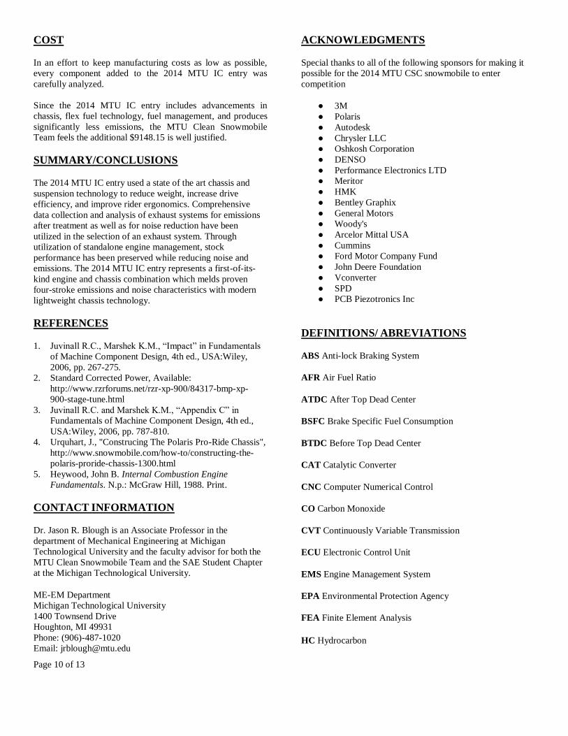
Figure 14: Original front engine mount with bracing
The front engine mount was analyzed because it was the most
practical to reduce weight on while not diminishing the
function or performance. The goal for the current front engine
mount was to reduce the weight by 30 percent. The model was
to have no internal sharp corners that would yield stress
concentrations and have radiuses, which would enhance
weight reduction and be easily manufactured. The components
were designed with a minimum wall thickness of 0.250” and
internal radiuses were designed at minimum 0.0625”. The
revised component can be seen in Figure 15.
Figure 15: Front engine mount model
FEA results produced the deflection of each mount. The
original mount yielded a deflection of 0.00013 inches and the
modified engine mount revealed a deflection of 0.00028
inches under maximum applied load.
Figure 16: Deflection of modified engine mount
The FEA analysis for the maximum stress on the lightened
engine mount can be seen below.
Figure 17: Stress results of modified engine mounts
Page 9 of 13
The result of maximum stress of the engine mount for the
modified configuration is 2,346 psi. 6061-T6 Aluminum has a
yield stress of approximately 40,000 psi, which yields a safety
factor close to 20. In conclusion, the aluminum mounts will
not fail due to the load.
Table 4: Weight reduction comparison chart
Part Name Initial
Weight
Final
Weight
Weight
Difference
Bottom Front
Engine Mount 2.67 Lbs 1.87 Lbs 0.8 Lbs
Shocks 10.2 Lbs 4.2 Lbs 6 Lbs
Body Panal
Spacers 0.2116 Lbs 0.06 Lbs 0.1516 Lbs
Carbon Fiber
Side Panels 2.09 Lbs 1.12 Lbs 0.97 Lbs
Spindle/A-arms
Assembly 16.71 Lbs 14.62 Lbs 2.09 Lbs
Exhaust 35 Lbs 20 Lbs 15 Lbs
As seen in Table 4 above, other changes implemented on this
year’s competition snowmobile included designing the
exhaust system. The team not only improved on the overall
engine performance, but substantially reduced the weight of
the overall system. The exhaust system from the 2013
competition sled weighed a total of 35 pounds. There were
two exhaust systems designed this year; one with a similar
design to the 2013 competition snowmobile, and one radically
different with a dual muffler design. After both designs were
completed, the new dual muffler design came out to be 20
pounds, while the other exhaust was 65 pounds. the team
decided to run the dual muffler design because of the major
benefit of the weight loss, compared to the other design.
To go along with improving upon the 2013 design, multiple
body panels were made with carbon fiber. Because of the
combination of a Polaris Indy chassis and body panels, with a
Ski-Doo seat and over-structure, custom panels had to be
made to bridge the gap between the gas tank and the cowl.
Last years snowmobile featured thermo-plastic molded panels.
This year, the team implemented custom carbon fiber panels
that are lighter, stronger, and more aesthetically pleasing.
By swapping out current OEM parts, the team was able to
reduce weight, starting by converting the front Walker Evans
suspension to aftermarket Fox Floats shocks. This was a direct
swap into the sled that saved a total of 6 lbs between the
shocks. The non-essential hardware on the snowmobile
including long bolts, steel bushings, and spacers were also
considered. By decreasing the diameter on some parts,
changing steel material out for aluminum, and shortening
bolts. A total weight savings of 1.54 lbs was accounted for.
ANTI-LOCK BRAKING SYSTEM
The 2014 MTU CSC Team implemented the Hayes TrailTrac
braking system. The TrailTrac system is an anti-lock braking
system that consists of both a hydraulic control unit (HCU)
and a Hayes electronic control unit (HECU). This system, in
combination with the Camoplast Ice Attak Track, will allow
the machine to slow with greater control by pulsing the brake
pressure to prevent long term locking of the track.
Brake lines run from the master cylinder on the handlebars to
the HCU, and then from the HCU to the brake caliper on the
snowmobile. The HECU is mounted on the air box to keep it
away from heat that is produced by the engine and exhaust
components. The HCU is located near the HECU and mounted
in between the intake plenum and gas tank, also keeping it
removed from heat that is being produced. The orientation of
the HCU is known to cause issues when bleeding the system,
therefore, the MTU Clean Snowmobile Team mounted the
unit horizontal to the direction of motion and with the fittings
upright to ease bleeding the system as shown in Figure 18.
Figure 18: Hayes HCU and HECU mounting locations.
The HCU was also bled by splicing the wire harness to cycle
the electric motor, as brake fluid was present, in order to fill
the piston with fluid and force out excess air.
Page 10 of 13
COST
In an effort to keep manufacturing costs as low as possible,
every component added to the 2014 MTU IC entry was
carefully analyzed.
Since the 2014 MTU IC entry includes advancements in
chassis, flex fuel technology, fuel management, and produces
significantly less emissions, the MTU Clean Snowmobile
Team feels the additional $9148.15 is well justified.
SUMMARY/CONCLUSIONS
The 2014 MTU IC entry used a state of the art chassis and
suspension technology to reduce weight, increase drive
efficiency, and improve rider ergonomics. Comprehensive
data collection and analysis of exhaust systems for emissions
after treatment as well as for noise reduction have been
utilized in the selection of an exhaust system. Through
utilization of standalone engine management, stock
performance has been preserved while reducing noise and
emissions. The 2014 MTU IC entry represents a first-of-its-
kind engine and chassis combination which melds proven
four-stroke emissions and noise characteristics with modern
lightweight chassis technology.
REFERENCES
1. Juvinall R.C., Marshek K.M., “Impact” in Fundamentals
of Machine Component Design, 4th ed., USA:Wiley,
2006, pp. 267-275.
2. Standard Corrected Power, Available:
http://www.rzrforums.net/rzr-xp-900/84317-bmp-xp-
900-stage-tune.html
3. Juvinall R.C. and Marshek K.M., “Appendix C” in
Fundamentals of Machine Component Design, 4th ed.,
USA:Wiley, 2006, pp. 787-810.
4. Urquhart, J., "Construcing The Polaris Pro-Ride Chassis", http://www.snowmobile.com/how-to/constructing-the-
polaris-proride-chassis-1300.html
5. Heywood, John B. Internal Combustion Engine
Fundamentals. N.p.: McGraw Hill, 1988. Print.
CONTACT INFORMATION
Dr. Jason R. Blough is an Associate Professor in the
department of Mechanical Engineering at Michigan
Technological University and the faculty advisor for both the
MTU Clean Snowmobile Team and the SAE Student Chapter
at the Michigan Technological University.
ME-EM Department
Michigan Technological University
1400 Townsend Drive
Houghton, MI 49931
Phone: (906)-487-1020
Email: [email protected]
ACKNOWLEDGMENTS
Special thanks to all of the following sponsors for making it
possible for the 2014 MTU CSC snowmobile to enter
competition
● 3M
● Polaris
● Autodesk
● Chrysler LLC
● Oshkosh Corporation
● DENSO
● Performance Electronics LTD
● Meritor
● HMK
● Bentley Graphix
● General Motors
● Woody's
● Arcelor Mittal USA
● Cummins
● Ford Motor Company Fund
● John Deere Foundation
● Vconverter
● SPD
● PCB Piezotronics Inc
DEFINITIONS/ ABREVIATIONS
ABS Anti-lock Braking System
AFR Air Fuel Ratio
ATDC After Top Dead Center
BSFC Brake Specific Fuel Consumption
BTDC Before Top Dead Center
CAT Catalytic Converter
CNC Computer Numerical Control
CO Carbon Monoxide
CVT Continuously Variable Transmission
ECU Electronic Control Unit
EMS Engine Management System
EPA Environmental Protection Agency
FEA Finite Element Analysis
HC Hydrocarbon
Page 11 of 13
HCU Hydraulic Control Unit
HECU Hayes Electronic Control Unit
IC Internal Combustion
KRC Keweenaw Research Center
LHV Latent Heating Value
MBT Maximum Brake Torque
MFB Mass Faction Burn
MSRP Manufacturer Suggested Retail Price
MTU Michigan Technological University
NOx Nitrogen Oxide
OEM Original Equipment Manufacturer
PE Performance Electronics
PTO Power Take Off
ROHR Rate of Heat Release
TDC Top Dead Center
WOT Wide Open Throttle
Page 12 of 13
APPENDIX A: Calculations for Butanol Percentages
Balanced Stoichiometric Combustion Equations(Ideal)
Butanol- (1)
Gasoline-
(2)
Stoichiometric AFR Calculations-Base Fuels
Butanol-
(3)
Gasoline:-
(4)
Stoichiometric AFR Calculations-Blended Fuels
Assumed Densities
Gasoline 719.7 kg/m^3
Butanol 810.0 kg/m^3
AFR's are on a mass basis, so densities were chosen.
(5)
(6)
(7)
(8)
(9)
(10)
32% Butanol
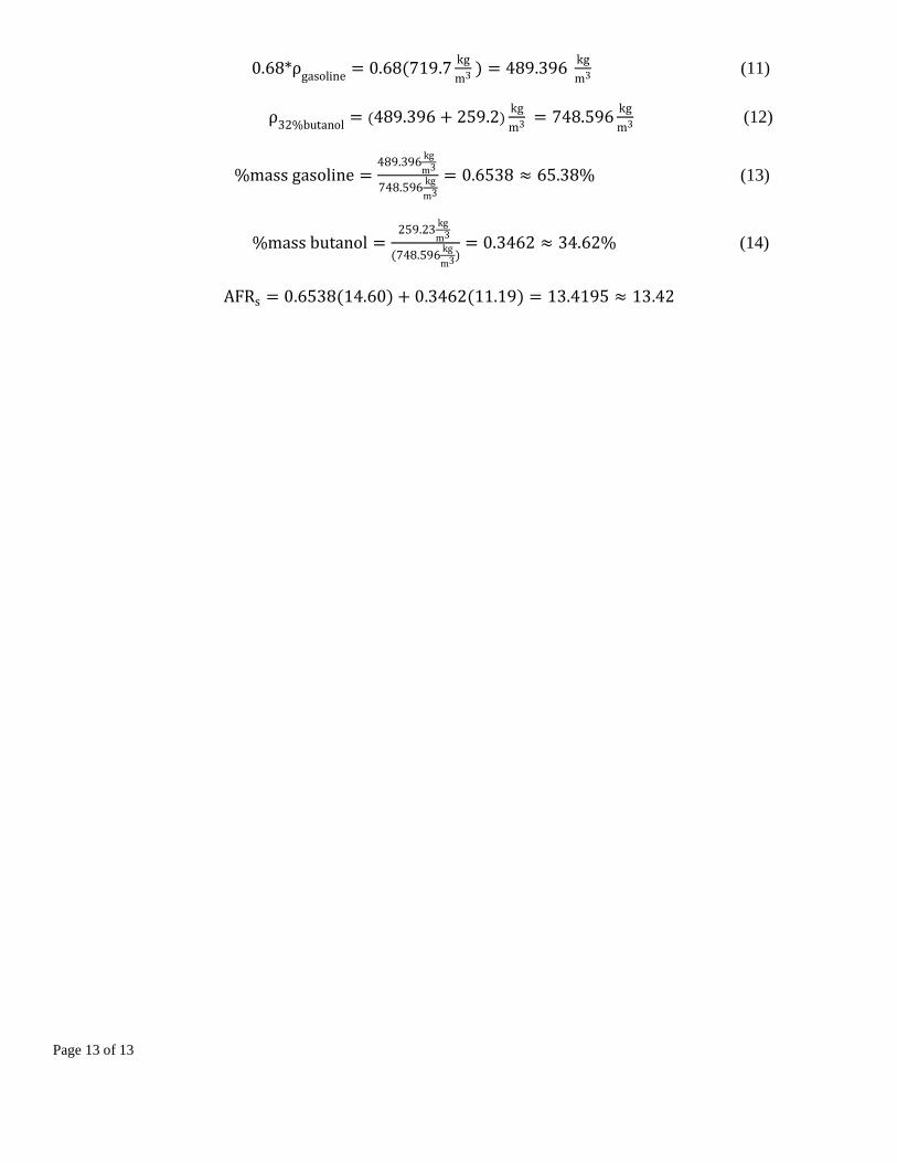
Page 13 of 13
(11)
(12)
(13)
(14)