Embed Size (px)
Citation preview

1
OIL REFINING INDUSTRY:GENERAL ASPECTS

1.1.1 The aims of refining
The series of treatments to which crude oil issubjected in order to obtain the desired range ofproducts is generically known as crude oil refining;as a consequence, refineries are the industrial plantswhere these treatments are carried out. Originally, theterm refining referred more specifically to anappropriate procedure for purifying a raw material(or unprocessed product), to render it more suitablefor use. In the past, only a single product wasobtained from petroleum by distillation, andsometimes by treatment with chemicals: lamp oil(kerosene). These treatments, which required onlymodest technology, constituted refining. Later, theterm refining came to be used to refer to all theincreasingly complex technological activities carriedout to obtain a series of intermediate outputs andcommercial products from crude mineral oils. Formost practical purposes, pure compounds are notrequired, but rather blends with specific marketableproperties. In other words, the properties of theseproducts are determined more by their suitability forpractical use than by their chemical composition.This gives the refining industry a certain degree offlexibility, not available to those producing purecompounds with a specific formula, such as thepetrochemical industry.
The products of refining can be grouped into anumber of main classes: a) industrial and domesticfuels (gas oils, fuel oils, Liquefied Petroleum Gas orLPG); b) motor fuels (gasolines, diesel, kerosene,LPG); c) feedstocks for the chemical andpetrochemical industry (virgin naphtha, LPG, olefins);d) other products (lubricating oils, bitumens, paraffins,solvents, sulphur).
The tendency to integrate refining with thepetrochemical industry from the beginning has led to
some processes, typical of the latter, beingincorporated into refineries, with the result of anadditional production of hydrogen, MTBE(methyl-tert-butyl ether) and olefins.
1.1.2 Historical development of the refining industry
The first refineries and their productsTraditionally, the birth of the modern petroleum
industry is dated to 1859, with reference to colonelEdwin Laurentine Drake’s discovery of the Titusvillereservoir in Pennsylvania. However, its beginnings canbe brought forward to 1855, when Benjamin Sillimanjr., a professor of chemistry at Yale University, afterhaving analysed a sample of crude oil, wrote afarsighted report which concludes: “Your companieshave in their possession a raw material from which, bya simple and not expensive process, they maymanufacture very valuable products. It is worthy ofnote that my experiments prove that nearly the wholeof the raw product may be manufactured withoutwaste, and this solely by a well directed process whichis in practice one of the most simple of all chemicalprocesses (in other words distillation)”. Silliman alsodemonstrated experimentally that one fraction ofpetroleum was particularly suitable for use in Franklinlamps in place of whale oil, whose price had becomeextremely high. The report gave rise to a series ofinitiatives and research projects, crowned with successthanks in part to the determination of colonel Drake,who began to use the percussion drilling technique inthe search for petroleum.
This event would not have had the decisivehistorical importance that it did, were it not for thecontribution made by the high quality of Pennsylvaniacrude: paraffinic, light, almost free from sulphur, rich
3VOLUME II / REFINING AND PETROCHEMICALS
1.1
Structures and schemes

in the kerosene fraction and capable of supplying goodlubricants.
After Drake’s discovery, extraction and refiningactivities developed very rapidly in the United States.Towards the end of 1870 there was already aflourishing petroleum industry, with about 150refineries. The largest of these, employed 200 staff totreat about 12,000 t/y of crude oil, mainly to producelamp oil. The main process carried out by the earlyrefineries was distillation, first run in batch in cheese-box stills, and later in a semi-continuous way usingbatteries of horizontal shell stills (Giavarini, 1989).The stills were connected to one another in a battery,with the residue passing from one to another, allowingthe heaviest fractions to be separated out gradually. Inthe most sophisticated models, the crude oil waspreheated, recovering heat from the hot productsexiting the system.
Lamp oil was first treated with sulphuric acidand then with caustic soda to remove the acid itself;it was subsequently washed with water. Often it wasthen redistilled with live steam and treated withbleaching earths to render it white and odourless likewhale oil, and of higher quality than coal oil or shaleoil which were foul smelling and smoky. The varioustypes of lamp oil were named for their colour andodour (Prime White, Standard White, Straw Colour,etc).
The distillation residue also began to be sold as alubricant, without treatment or after treatment withsulphuric acid (bright stock). The lubricants obtainedfrom Pennsylvania crude had fairly good properties,and became established despite the primitive refiningtechnique.
Towards the end of the Nineteenth century,Herman Frash, known for having revolutionized thesulphur market with his innovative extractionprocess, had an idea which allowed the range oftreatable crudes to be broadened considerably; suchrange was previously restricted to those with anextremely low sulphur content. By using copperoxide he managed to ‘sweeten’ the fraction used forlamp oil, obtaining a product which did not give offunpleasant odours when burned. The same periodalso saw the first attempts of the combustion of the‘long’ residues of distillation, in fixed industrialplants or to propel ships; however, these fuels becamewidespread only very slowly.
At the end of the Nineteenth century, tworevolutionary inventions by Thomas Edison andGottlieb Daimler and Carl Benz begin to make theirinfluence felt in the petroleum world, too, marking thebeginning of a new era. In the United States, Edisonhad developed a new lighting system: the electric lightbulb. In Germany, Daimler and Benz had successfully
applied their internal combustion engine to a variety ofvehicles.
At the turn of the Twentieth century, the demandfor lamp oil thus fell drastically, and the demand forgasoline skyrocketed. Exploration was intensified andnew wells were drilled; simultaneously, however, asystem was sought to obtain more gasoline from crudeoil. The concept was clear: the molecules of theheavier components had to be cracked to produce thelight constituents of gasoline.
English researchers had noted that heat andpressure influenced cracking reactions. The firstpatents appeared, but their practical implementationran into difficulties: if the residue from distillation isoverheated, the main product is coke. At this point,another chemist gifted with imagination and greatperseverance entered the scene: the American WilliamM. Burton, who in 1911 perfected the crackingprocess. This was not easy: more than two years oftests, complicated by the need to work at hightemperature and high pressure, when riveting was stillthe most reliable way of joining metal sheets.
Due to funding problems, Burton saw his reactors(9 metres tall) installed only in 1913, and immediatelydemonstrated that the amount of gasoline obtainablefrom a barrel of crude could be doubled at the expenseof heavy distillates. This represented a significantturning point for the oil industry. It immediatelybecame clear that technological innovations in thissector were extremely profitable, leading to thedevelopment of more organized and systematicresearch. It is worth remembering that the firstBurton-Clarke units used coal on a moving grid in theprocess furnace.
The first decade of the Twentieth century did notbring any great novelties, with the exception of the useof the first coil heaters (pipestills), which encouragedthe spread of continuous distillation. These heatersrepresented a significant technological advance, sincethey allowed the crude oil to be heated in a controlledway. The construction technique derived from thatused for steam boilers. However, the pipestills becamewidespread only many years later.
The foundations of the modern refining industryThe second decade of the Twentieth century was
crucial for the definitive take-off of the modernrefining industry, especially in Europe. The growingspread of the automobile led to the increasinglywidespread installation of gasoline pumps. A growingnumber of applications were also found for dieselengines; however, these were for the time beinglimited to fixed plants and ships’ engines. The FirstWorld War demonstrated the usefulness of motorizedtransport, and also saw the first use of aeroplanes for
4 ENCYCLOPAEDIA OF HYDROCARBONS
OIL REFINING INDUSTRY: GENERAL ASPECTS

war; even in preceding years it was easy to forecast anincrease in the need for fuels, aggravated by the factthat many new reservoirs (for example, Mexico 1907,Iran 1908) did not have the same quality and yields ofthe first Pennsylvania crudes.
One disadvantage of the Burton process was theheavy deposition of coke, which made it necessary tostop and clean the unit after a few hours of operation;the process therefore required further improvement.Another famous oil industry pioneer devoted himselfto this task: the American Carbon Petroleum Dubbs, arare example of perfect correspondence betweensomeone’s name and their profession. Alongside hisfather James, Dubbs was a member of a formidablegroup of scientists who set up the first genuine processcompany in the petroleum sector (now UOPs,Universal Oil Products). Dubbs’ father had developed,and applied in 1912, a simple process to separatepetroleum from the emulsified water which itfrequently contains: it was sufficient to heat it in coilsand then send it for separation. Dubbs applied this ideato cracking: he heated the feedstock in small-diameterpipestills and then sent it to an unheated chamberwhere cracking continued. The coke was deposited inthis chamber, which could be by-passed and cleaned(Fig. 1). The process was now really continuous; inaddition, non-converted products could be recycled.The plant was ready in 1919 and immediately becamea success, so much so that the oil companies mostinterested in it chose to buy Dubbs’ company directly,rather than pay the considerable royalties.
The idea of preheating the crude oil in coilfurnaces was eventually applied to distillation; the firstfractionation column of modern design, however, onlycame into operation in 1928. The Dubbs’ innovationsprobably marked the beginning of the modern refiningindustry.
Dubbs’ introduction of cracking was followed by adecade (1920-30) of continuous development:distillation technologies were perfected; vacuumdistillation appeared to increase the yield of distillates
and produce bitumen; the thermal reforming processwas introduced, which, fed with gasoline fractions,improved their octane number and thus their quality.Other thermal processes, such as visbreaking andcoking, can be considered derivatives of Dubbs’ basicscheme. In those same years, again in the UnitedStates, the production of lead tetraethyl began, used asan antiknock additive for gasolines (Giavarini, 1990).
Europe was not without developments inpetroleum technologies: suffice it to think of Bormanndistillation plants, the Bergius hydrogenation process,the refining processes for mineral oils, and so forth.Without counting the numerous European scientistsworking in many American process and refiningcompanies. However, from an industrial and strategicpoint of view, Europe still lagged behind in the seconddecade of the Twentieth century. During the FirstWorld War, the major Empires could depend upon agood refining infrastructure and sufficient oilresources; Great Britain could count on supplies fromthe East and Russia, though lacking in organizationand technology, had vast resources. France and Italywere the least well-prepared, and therefore had to besupplied by the United States during the war.
The advent of catalytic processesIt is well-known that catalysts are substances able
to selectively accelerate chemical reactions, and thusto propel specific chemical processes in the desireddirection.
The first conversion processes used in the oilindustry (of thermal type as seen above) wereinefficient from the point of view of specific yields,and produced significant quantities of by-products.Thermal cracking in particular had demonstrated all itslimitations by the early 1930s; these limitationsbecome evident halfway through the decade, when thewarning signs of war began to appear. Squadrons offighter planes, with their increasingly efficientengines, required large quantities of high octanegasoline; it was already clear that whoever had the
5VOLUME II / REFINING AND PETROCHEMICALS
STRUCTURES AND SCHEMES
heating furnacepressuredistillate
condenser
feedstockpumps andcontrol valves
dephlegmator
residuum drawoff
residuumdrawoff
vapour line
cold feedstock todephlegmator
return to heater
to pressuredistillate
fractionator
oil vapours
decokingmanhole
reac
tion
cham
ber
vapour
Fig. 1. Diagram of the firstDubbs thermal cracker(Aalund, 1977).

most efficient air force would have an advantage inany potential war. The Germans, rich in coal resources,chose to follow the (catalytic) route of producing fuelsfrom this.
In the refining industry the time was ripe for thebirth of the ‘king of processes’: catalytic cracking.Few events in the history of industry have had such aprofound impact as the introduction of this process,immediately followed by the transformation ofnumerous other petroleum processes into catalyticprocesses. The advent of catalytic cracking, linked tothe name of Eugène Houdry, marked the end of thephase of the great inventors; after this, developments(though numerous and significant) were increasinglyless the result of individual initiatives.
Houdry, an engineer of French origin, worked on acatalytic process allowing more and higher qualitygasoline to be produced. For three years he tested allpotential catalysts, and discovered that materials basedon alumina-silicate, such as certain fired clays, workedwell. However, a layer of coke resulting from thepyrolysis of the hydrocarbons formed on the catalyst;Houdry resolved this problem by burning the coke andrecycling the catalyst. Unable to put his idea intopractice on an industrial scale in Europe, Houdrydeparted for the United States where, with the help offunding from an oil company, he set up the HoudryProcess Corporation. In 1937, the first fullycommercial unit came on stream. When war broke outin 1939, the United States already had 12 catalyticcracking plants.
The catalytic alkylation process was alsodeveloped simultaneously in Great Britain and theUnited States during the late 1930s; by blendingtogether light hydrocarbons, not otherwise used ingasolines, alkylation made it possible to produceaviation gasoline of exceptionally high quality.
The first catalytic cracking processes were cyclic,with the catalyst placed in fixed bed reactors, andcaused numerous problems. The Houdry Corporationitself developed the first moving bed process. Almostsimultaneously, in 1942-43, the fluid bed processappeared, representing another formidabletechnological innovation.
The purposes of cracking are mainly quantitative:its main aim, as seen above, is to increase gasolineyields. Reforming, by contrast, serves to increase theoctane number of gasoline or to produce aromatics.The precursor of catalytic reforming washydroforming, which used a molybdenum basedcatalyst; during the Second World War this suppliedthe United States with the toluene needed to producetrinitrotoluene.
The first modern catalytic reforming process forgasolines, using a platinum-based catalyst, dates to
1949, and led to the immediate abandonment ofthermal reforming.
As a valuable by-product the catalytic processproduces large quantities of hydrogen: this allowed forthe development of catalytic desulphurizationprocesses based on the use of hydrogen(hydrodesulphurization), making it possible tocommercialize products more in keeping withincreasing environmental concerns.
On the eve of the Second World War, worldwiderefining capacity had reached 354 million tonnes peryear, two thirds of this in the USA. By the year 2000,this capacity had multiplied tenfold, spread over morethan 700 refineries.
The environment and energy saving in the mostrecent developments in the refining industry
During the second half of the Twentieth century,the refining industry was affected by two significantphases of transformation; while these did not radicallyalter its structure, they did contribute significantly tothe evolution of processes and technologies. The firstof these phases mainly affected the decade 1970-80,following the first so-called oil crisis (1973), markingthe end of a long period of ‘easy petroleum’ (in otherwords at modest prices).
The response of industry was to rationalize allprocesses (especially distillation) involvingsignificant energy consumption, in order todrastically reduce waste through more rigorousenergy recovery (optimization of the heat exchangebetween effluent streams and incoming crude).Rationalization also involved an improvedexploitation of the capacity of individual refineries,and the closure of those which were less efficient interms of technology and energy use.
The second phase of transformation, characterizingthe final two decades of the Twentieth century and thefirst of this millennium, has been characterized mainlyby interventions dictated by environmental factors(Giavarini, 1993). These can be summarized asfollows: a) reduction of residue, in other words of the‘bottom of the barrel’ and therefore of black products(fuel oils), with a consequent increase in distillateproducts, especially gas oil and diesel; b) increasinglydrastic reduction of sulphur in fuels on the one hand,and the need to desulphurize a larger number ofproducts on the other, as a consequence of the increasein middle distillates; c) removal of lead fromgasolines; d) reduction of aromatic compounds,especially benzene, in fuels.
In some countries, the main objective was achievedpartially in the medium term by revitalizing oldvisbreaking processes, suitably adapted to meet thesenew requirements. However, the most rational
6 ENCYCLOPAEDIA OF HYDROCARBONS
OIL REFINING INDUSTRY: GENERAL ASPECTS

solution, though not the cheapest, involved installingcatalytic conversion processes using hydrogen(hydrocracking), served by purpose-built plants for theproduction of hydrogen. In some countries, residuegasification processes were introduced, with thesimultaneous production of electrical energy.
The resulting need to treat more distillates, and tocarry out a more stringent desulphurization (down to10 ppm or less) of some products led to a significantincrease in severe desulphurization units. Thisincreased desulphurization capacity augmented theneed for hydrogen, required in larger quantities thanthose supplied (as a valuable by-product) by catalyticreforming units. The larger quantities of hydrogensulphide produced by desulphurization also led to anincrease in the number of plants to turn this gas intosulphur.
Mild hydrocracking units were also developed byimproving the hydrodesulphurization process.
The removal of lead from gasolines led tosignificant technical modifications of the catalyticreforming process, which now operated at extremelylow pressures and with more active catalysts. Inpractically all refineries, the isomerization process forfractions C5-C6 was introduced, in its high conversionefficiency version.
Catalytic cracking processes also evolvedqualitatively to produce gasolines with a higher octanenumber. The benzene content was controlled withseparation and hydrogenating conversion processes.The need to use MTBE in some cycles led a number ofrefineries to construct plants to produce this.
In recent decades, the refining industry hasbenefited from the significant development ofquantitative methodologies (models of reactions,kinetics, reaction engineering, automation and control,etc), which have allowed the control of processes andthe quality of products to be considerably improved.Thanks to its characteristic flexibility and rapidadaptation, the refining industry has always been ableto respond to the numerous quality requirements andvariations in demand.
1.1.3 Refining schemes
A refinery is a complex plant consisting of variouscomponents (see Section 1.1.4). The most importantand characteristic part consists of the plants, orprocess units, used to refine crude oil. The variousprocesses can be subdivided into the followingtypologies: a) separation units, which obtain thevarious (intermediate) fractions from crude petroleum,usually sent for further treatments; this separation isobtained mainly with distillation processes, and other
processes of physical type; b) conversion (cracking)units to turn heavy fractions into lighter fractions, inorder to increase the yield of specific products (suchas gasoline); c) units to improve the quality of somefractions (or ‘cuts’) by acting on the chemicalcomposition of their constituents; d) units for theremoval of unwanted components (such as sulphur); e)units to produce lubricating oils (present only in alimited number of refineries).
Units for the blending of the various cuts, andadditivation units, which contribute to making thefinished commercial products, are not generallyconsidered process units in the strict sense.
Separation unitsThe most important and widespread physical
separation units are those for distillation. All refinerieshave at least one atmospheric distillation (primarydistillation or topping) unit, which separates the crudeoil into various fractions with different boiling ranges.Simple in concept, since this is an elementary physicalseparation, the process is complex from anengineering point of view, since it includes a series ofheat recovery units and also incorporates the desaltingof the crude oil. This is the only unit which treats allthe feedstock crude, and is therefore also extremelylarge.
Generally speaking, atmospheric distillation isfollowed by vacuum distillation in order to recoveradditional distillates from the topping residue(obtained at about 350-380°C) without increasing thetemperatures; at higher temperatures, the molecules ofthe heavier hydrocarbons would crack uncontrollably.
Separation units also include deasphaltingprocesses which extract non-asphaltic hydrocarbonsfrom the vacuum distillation residues using solvents(light paraffins); the non-soluble residue is a solid orsemi-solid product, rich in asphaltenes, metals, saltsand sediments.
Other separation processes (treatment with aminesor other solvents) are used to extract hydrogensulphide (H2S) from refinery gases; this is then sent tothe sulphur production plant. Various separationprocesses using solvents are also used to obtainlubricating oils.
Conversion unitsNot all refineries are equipped with conversion
units; traditionally, in fact, refineries have beensubdivided into simple cycle refineries andconversion refineries, referring especially tocatalytic cracking units.
Conversion may be of exclusively thermal type,and involve distillation residues (visbreaking andcoking units), or distillates (thermal cracking). The
7VOLUME II / REFINING AND PETROCHEMICALS
STRUCTURES AND SCHEMES
classical conversion processes, however, mainlyinvolve catalytic crackers, traditionally used to treatthe heavier distillate fractions obtained from vacuumoperation (and in part also the residues), andhydrocracking units. Originally developed to treatheavy paraffinic distillates, hydrocracking units cantoday be fed with residues (hydroconversion); theseresidues can also be used as fuel oils or, if suitable, asbitumens. Lower demand for fuel oil has led to thedevelopment of special deep conversion processes,based on the cracking of residues in the presence ofhydrogen to produce distillates with a modest sulphurcontent.
In more recent times, the drastic conversion ofresidues into gas has also been obtained with theintroduction of gasification (partial oxidation)processes, based on technology previously applied tosolid fuels. In the presence of steam and oxygen,heavy hydrocarbons are turned into hydrogen andcarbon oxide which, suitably purified, can also be usedas a fuel for the production of electrical energy,exportable outside the refinery.
Units to improve the quality of distillatesThe first and best known unit of this type is the
catalytic reformer, developed to improve the octanenumber of the heavier fractions of gasoline (heavyvirgin naphtha) by increasing aromatic hydrocarbonsand those of isoparaffinic type.
The isomerization unit, on the other hand, is fedwith the paraffinic fractions of light virgin naphtha(especially C5 and C6), to turn these into isoparaffins.In some cases, it may also be used for C4 fractions,especially to prepare the feedstock for alkylationplants.
The alkylation plant, by contrast, is used to treatthe olefinic fractions C3 and C4 from crackers, turningthem into branched C7 e C8 components with a highoctane number by reaction with isobutane.
This category also includes polymerization (ormore accurately dimerization or oligomerization)units, which recombine specific gaseous fractions oflower value in the form of liquid hydrocarbons, andetherification units for the production of high octanecomponents (for example MTBE or ETBE,methyl-tert-butyl ether or ethyl-tert-butyl ether).
Units for the removal of unwanted componentsGenerally speaking, all components of crude oil
which are not hydrocarbons in the strict sense (in otherwords formed of C and H) cause problems both ofenvironmental type and relating to the quality ofproducts. These components include salts, sulphur andnitrogen compounds and metals. The salts dissolved inthe water emulsified with the petroleum are removed by adesalting unit inserted within the topping column.Sulphur, present in molecules with a varying degree ofcomplexity, is removed using purpose-builthydrodesulphurization units (HDS), which also act onmolecules containing nitrogen, oxygen and heavy metals.
The hydrotreating units (HDS) are the mostwidespread in refineries: the sulphur is turned intohydrogen sulphide, which is in turn turned intoelementary sulphur in special units (Claus-type units).Specific light fractions, rather than being treated withhydrogen, may be subjected to other processes toconvert mercaptans into less corrosive andfoul-smelling compounds (Merox-type units); if thecompounds thus formed are not removed, theprocesses are described as ‘sweetening’.
8
OIL REFINING INDUSTRY: GENERAL ASPECTS
ENCYCLOPAEDIA OF HYDROCARBONS
crude oil
fuel gas and LPG
fuel gas and LPG
light naphtha
reformer naphtha
sulphur
oil (kerosene)
gasoil
bitumen/fuel oil
fuel oil
H2
H2
H2S
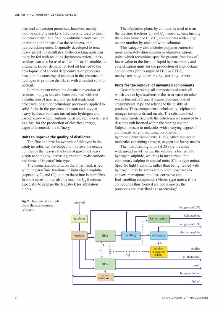
Fig. 2. Diagram of a simplecycle (hydroskimming)refinery.

Plants for lubricantsLubricants are among the most sophisticated
products of refining, and have a high added value.However, considering that demand for these is lowerthan for other petroleum products, they are producedonly in a limited number of refineries; some side cutsand the residue from vacuum distillation are used toproduce the base stocks for lubricants. Thesefractions are then treated in a series of purpose-built
units to improve their viscosity index, behaviour atlow and high temperatures, colour, stability etc.Blending and additivation represent the final stagesof this process.
Very frequently the base stocks for these oils aresold to specialized companies outside the refinery,which make the finished product. Lubricating oilsprepared using synthetic base stocks are increasinglycommon (see Chapters 1.2 , 8.1 and 8.2).
9VOLUME II / REFINING AND PETROCHEMICALS
STRUCTURES AND SCHEMES
crude oil
fuel gas and LPG
fuel gas and LPG
light naphtha
reformer naphtha
sulphur
oil (kerosene)
gasoil
fuel gas and LPG
bitumen/fuel oil
H2
H2
H2S
fuel oil
crude oil
fuel gas and LPG
fuel gas and LPG
light naphtha
reformer naphtha
sulphur
oil (kerosene)
gasoil
fuel gas and LPG
bitumen/fuel oil
coke
H2
H2
H2S
fuel oil
Fig. 4. Thermal conversioncycle with coking.
Fig. 3. Thermal conversioncycle with visbreakingand thermal cracking.

10 ENCYCLOPAEDIA OF HYDROCARBONS
OIL REFINING INDUSTRY: GENERAL ASPECTS
crude oil
fuel gas and LPG
fuel gas and LPG
fuel gas and LPG
light naphtha
reformer naphtha
sulphur
oil (kerosene)
gasoil
fuel oil
bitumen
H2
H2
H2S
cracker naphtha
alkylated naphtha
cycle oil
crude oil
fuel gas and LPG
fuel gas and LPG
fuel gas and LPG
light naphtha
reformer naphtha
sulphur
oil (kerosene)
gasoil
bitumen
H2
H2
H2
H2S
fuel oil
hydrocracking naphtha
Fig. 5. Catalytic conversioncycle with FCC andalkylation.
Fig. 6. Catalytic conversioncycle withhydrocracking.

Refining cyclesWith the exception of unusual cases of refineries
devoted, for example, to the exclusive production ofbitumens and fuel oils or lubricants, refining schemesmay be of simple type (hydroskimming) or morecomplex type; the latter typology comprises bothconversion (thermal and/or catalytic) refineries and themore complex deep conversion refineries.
Bearing in mind that two identical refiningschemes are unlikely to exist, we can attempt to makea subdivision into the following typical cycles: a)simple cycle (hydroskimming); b) thermal conversioncycle: scheme with visbreaking (and thermal cracking)and scheme with coking; c) catalytic conversion cycle:scheme with cracking (FCC, Fluid Catalytic Cracking)and scheme with hydrocracking (HDC); d) deepconversion cycle: scheme including thehydroconversion of residues and scheme withdeasphalting and gasification; e) production oflubricants. For the sake of brevity and clarity, theschemes described below have been simplified.
Many refineries fall into more than one category;for example, they may have both visbreaking orcoking, and catalytic conversion plants (FCC, HDC).
Simple cycle refineries (Fig. 2) are traditionallyequipped with crude oil distillation plants,desulphurization units for distillates, and with units,above all for reforming, to increase the octane numberof gasolines. The hydrogen for hydrodesulphurizationis supplied by the reforming units. More recently, dueto the reduction or elimination of antiknock additives,reforming units have been accompanied by units forthe isomerization of the C5-C6 cut. During the secondhalf of the Twentieth century, units for thetransformation into sulphur of the H2S produced byhydrodesulphurization units and separated in purpose-built units also became widespread. Once fairlycommon in Europe and elsewhere, this cycle is nowrarely used in industrialized countries.
In addition to the units in the hydroskimmingscheme, the thermal conversion cycle also includesvisbreaking units (plus thermal cracking) or cokers(Figs. 3 and 4); these represented the first generation ofconversion processes (see Chapters 5.1, 5.2 and 5.3).Visbreaking (VB) and coking have always beenrelatively important, given their ability to treat theresidues of distillation (atmospheric and now alsovacuum distillation) in a relatively simple andeconomical way. Coking in particular may alsorepresent the basic process in a deep conversionrefinery if a use is found for the coke produced(combustion, sale or gasification). Yields, especially inthe case of visbreaking, are not high; the same is trueof the quality of the products. However, there is anincrease in middle distillates (in the case of VB) or
light products in general (in the case of coking), andthis improves the refinery’s operational flexibility.However, this cycle is unable, at least in its simplestform, to meet the quality and environmentalrequirements of a modern industrialized country.
Catalytic conversion refineries are equipped, inaddition to the other units, with more traditionalconversion plants (see Chapters 6.1 and 6.2), especiallythose for catalytic cracking and/or hydrocracking(Figs. 5 and 6). From the beginning, catalytic cracking,or FCC, has been more popular in the Americanrefining system than in the European system. Often, thecatalytic cracker is followed by an alkylation plantwhich uses the gaseous by-products of FCC.Hydrocracking, which necessarily requires the presenceof purpose-built plants for the production of hydrogen(steam reforming), became widespread later, andrepresents the basis of many modern refining cycles.
Deep conversion refineries have upgrading unitssuitable for the conversion of residues, to make thesemore environmentally friendly and to maximize theproduction of distillates and light products.Traditionally, upgrading processes are classified intocarbon rejecting and hydrogenation typologies.Alongside coking and visbreaking, the formercategory includes deasphalting processes usingsolvents. The second category includes the variousversions of hydroconversion processes. A separatecategory comprises gasification processes of IGCCtype (Integrated Gasification Combined Cycle, seeChapter 7.3). The catalytic cracking process (FCC)itself can be partially fed with residues (see Chapter6.1). The choice of process depends on the propertiesof the residue to be treated: above all viscosity and itscontent in contaminants, such as asphaltenes andmetals (see Chapter 7.2).
Among the various possible configurations, Figs. 7and 8 show two possible deep conversion cycles.Gasification may also be included after coking (seeagain Fig. 4) to use the coke produced, or visbreaking(see again Fig. 3) to gasify the residue (tar).
The production of lubricants requires the presenceof special units, usually in addition to those present inthe preceding cycles. The feedstocks used aredistillates selected to optimize quality and yields, andminimize by-products.
As stated earlier, the traditional bases for lubricantsare the products of vacuum distillation, which are firstsubjected to an extraction process using solvents toseparate out aromatics and paraffinic waxes. Residuemay also be used, with a prior removal of asphalticcomponents.
Treatments with solvents may be replaced byhydrorefining processes (such as HDC, see Chapter8.2), perfectly integrated and already present in
11VOLUME II / REFINING AND PETROCHEMICALS
STRUCTURES AND SCHEMES

some of the refining schemes considered. Thisallows for the production of base stocks forlubricants with good yields and excellent quality,starting from crudes traditionally unsuited to thispurpose.
Fig. 9 shows an integrated scheme for theproduction of oils, both with solvent extraction andwith HDC.
Refinery’s conversion ratio and complexity indexThe conversion ratio is generally defined as the
ratio of the sum of the capacities of individualconversion units to the capacity of the atmosphericdistillation plant. The conversion units are compared tocatalytic cracking using coefficients (FCC equivalent)which ‘weigh’ the capacity of individual units toconvert heavy products into lighter and more valuablefractions. So for example:
• FCC 1.00• VB 0.33• coking 1.70• hydroconversion 1.20• deep conversion 2.10
conversion ratio�
FCC capacity�0.33 VB capacity�1.70 coking capacity� ...�111111111111111111111144444444444444
distillation capacity
The complexity index, or factor, of a refineryserves to give an idea of its structure and ‘value’,since it takes into account the cost of each plantrelative to its unit production capacity; this isthen related to the cost of the distillation unit pertonne of capacity.
Thus, if a given plant required an investment fivetimes higher than that of the topping plant per unit offeedstock, but its capacity is 1/6 that of the toppingunit, the partial complexity index for that plant can becalculated by multiplying the coefficient 5 by itscapacity relative to the topping unit, and therefore:
complexity index = 5�1/6=0.84
As an example, the complexity indexes forreforming and catalytic cracking are 3.4 and 7.2respectively. The overall complexity index for thewhole refinery is the sum of all the partial complexityindexes.
To give an idea of orders of magnitude, a simplecycle refinery may have a complexity index of 3-5; aconversion refinery using classic processes will havean index of 7-9; a complex refinery will generallyhave an index of over 10.
Treating crude oil requires the consumption ofenergy in the form of various types of fuel (refinerygases, methane, fuel oil, coke); in other words, the
12 ENCYCLOPAEDIA OF HYDROCARBONS
OIL REFINING INDUSTRY: GENERAL ASPECTS
crude oil
fuel gas and LPG
fuel gas and LPG
fuel gas and LPG
light naphtha
reformer naphtha
sulphur
gasoil
bitumen
H2
H2
H2
H2S
fuel oil
hydrocracking naphtha
oil (kerosene)
Fig. 7. Deep conversioncycle usinghydroconversionprocesses.

refinery consumes a certain amount of the incomingcrude. A smaller percentage is consumed due to lossesof various types (vaporization, accidental losses,discharge from relief valves, etc.). Obviously, the more
complex a refinery is, the greater both consumption andlosses.
The diagram in Fig. 10, showing a conversion cycleequipped with FCC, alkylation and hydrocracking
13VOLUME II / REFINING AND PETROCHEMICALS
STRUCTURES AND SCHEMES
crude oil
fuel gas and LPG
fuel gas and LPG
fuel gas and LPG
light naphtha
reformer naphtha
sulphur
oil (kerosene)
gasoil
electric power
bitumen
H2
H2
H2
H2S
fuel oil
hydrocracking naphtha
syngas
topping residuum
paraffins
aromatic extracts
gas, naphtha, gasoil
asphalt
Fig. 9. Integrated cycle for the production of lubricating oils in a refinery equipped with hydrocracking units (HDC).
Fig. 8. Deep conversioncycle with deasphalting(precipitation ofasphaltenes with solvent)and gasification (IGCC).

units, in addition to reforming and isomerization units,gives a quantitative indication of typical yields andconsumption for the various treatments (Iadanza,2004).
1.1.4 The structure and complexityof refineries
Refineries, in other words the plants where crude oil istreated to obtain the desired range of products, arecomplex entities consisting of: a) a sequence ofprocess units linked together according to differentschemes, as seen above; b) utilities to generate anddistribute electrical energy, steam, purified water,compressed air, nitrogen, fuels for internal use, etc.; c)storage tanks for crude oil, intermediate and finishedproducts; d) systems to transport crude oil,intermediate and finished products.
At the beginning of the year 2000, there werearound 730 refineries worldwide, with a treatmentcapacity of about 4 billion tonnes of crude oil.Refineries are classified on the basis of their
capacity, expressed in t/y or in barrels of crude oiltreated per working day (to calculate the latter fromthe former divide by 50), and on the basis of thetreatment scheme adopted. No two refineries workin a completely identical way; the differences aredetermined by market conditions for the product andthe properties of the raw material. A considerableamount of space is taken up by the tanks used tostore crude oil (working storage), intermediateproducts and the various finished products; the areaneeded is thus much larger than that of a chemicalplant, in part also due to safety requirements (safetydistances).
In the years before the Second World War, theground plan of refineries differed considerably fromthat of today. Starting from the second half of the 20thcentury, plants characterized by greater practicalitywere built, based on the following concepts: a) creation of one or more areas for storage tanksseparate from the plants; b) unitary design of thetreatment cycle and its predictable developments; c) grouping of plants in a single zone, but coveringvarious areas, with a single control room;
14 ENCYCLOPAEDIA OF HYDROCARBONS
OIL REFINING INDUSTRY: GENERAL ASPECTS
LPG
lightatmosphericdistillate(30-180°C)
downstreamprocesses(isomerization/reforming)
downstreamprocesses(HDS/dewax)
downstreamprocesses(HDC/FCCalkylation)
cons. and lossessulphur
cons. and lossessulphur
cons. and lossessulphur
1.22
16.90
LPGblending
LPG
virgin naphtha
gasoline
jet fuel
gasoil(of whichdiesel)
fuel oils
bitumen
sulphur
consumption
losses
2.72
7.50
3.60
34.89
25.50
15.63
2.50
1.03
6.55
0.50
100.00
2.72
S sulphur 1.03
S consumption and losses 7.05
naphthablending 25.09 25.09
kerosene andgasoilblending
38.49
blending of
fuel oilsbitumen
15.632.50
33.63
8.194.863.33
3.010.07
1.100.58
1.240.38
mediumatmosphericdistillate(180-360°C)
heavy vacuumdistillate(360-550°C)
vacuum residuum(� 550°C)
consumption and losses
1.5
7.5
21.2
35.3
18.0
14.8
1.7
crude oil(100%)
Fig. 10. Typical yields of a conversion refinery (% of crude oil mass).

d) concentration of the production of steam andelectrical energy in a single plant; e) centralization ofmaintenance programming; f ) concentration ofeffluent treatment systems in specific sites;g) identification of areas for expansion anddevelopment, for both plants and storage tanks.
Fig. 11 (Rumbold, 1971) shows the ground plan of atypical refinery of the second half of the Twentiethcentury, which is in some ways still relevant to today. Therefinery is divided into a number of areas (‘islands’),each of which hosts one or more plants; the islands areseparated by safety zones which form a network of roads,essential for the plants to work safely. Storage tanks aregrouped in separate areas. If the refinery is on the coast,it takes advantage of the availability of mooring facilitiesfor reception and delivery.
Some fundamental design criteria derive fromregulations and legal requirements, or from unificationprocedures. The type, shape and modular dimensionsof storage tanks are thus standardized; the process
units are outside, with the exception of some specificmachinery and appliances and the remote controlinstruments, grouped in a single building (controlroom). Heat exchangers, usually of the tubular typewith floating heads, are generally of standardizedlength; also standardized are the diameters, thicknessand flanging of pipelines. All electrical appliances areof explosion-proof type. The gaseous discharges fromrelief valves are sent to the flare.
The inspiring principles listed above remainfundamentally valid; to these have been added designand management criteria dictated by a greatersensitivity towards safety and the environment. So, forexample, the old control rooms equipped withwindows and initially located in the middle of theplants zone, have been replaced by bunkers inreinforced concrete, resistant to explosions and fires,and which ‘see’ the plants only through controlinstruments and television cameras. The complexitiesof safety and environmental protection are discussed
15VOLUME II / REFINING AND PETROCHEMICALS
STRUCTURES AND SCHEMES
gas unit
atmospheric distillation
alkylation
n-butane isomerization
catalytic cracking anddistillation unit
vacuum distillation
control room
torch
workshop and warehouse
API separator
power plant
bitumen blowing
sulphur production
service fluids
bitumen loading
waste water treatment
cooling towers
catalytic reforming
hydrodesulphurizationlaboratory
fire fighting trucks garage
office building
tank truck loading
LPG tanks
pumping station
railwayconnection
26
26
electric power cabins27
2727
27 27
25
25
24
24 24
23
23
22
22
21
21
20
20
19
19
18
18
17
17
16
15
14
13
13
12
12
11
11
10
10
9
9 9
8
7
7
6
6
5
5
4
4
3
3
2
2
1
1
88
8 8
14
15 1616
Fig. 11. Typical ground plan of a refinery of the second half of the Twentieth century.

in Chapters 9.1, 9.2. Fig. 12 shows an overview of amodern refinery.
The evolution of processes is dictated by socialand, especially today, environmental needs. As aconsequence, the current structure of the cycles, andthus of the plants, takes into account the need toconvert residues to obtain a greater production ofdistillates (especially higher quality diesel) and/orhydrogen. Partial oxidation (gasification), thoughrequiring substantial investments, has becomeincreasingly important. As a result, deasphaltingprocesses have been revitalized, and thermal processes(such as cracking, visbreaking and coking), whichsupply the feedstock for IGCC plants have beenmaintained or even expanded. Desulphurization plantshave been improved in terms of both quality andquantity.
The integration of refining and thepetrochemical industry has followed two mainprinciples: according to the first, the refinery mustbe adjacent to the petrochemical plant, but separatefrom it; according to the second (less frequent), therefining plants must be located inside thepetrochemical complex, with shared utilities andintegrated management.
Modern refineries have adopted some processespreviously typical of the petrochemical industry;
principal among these is the production of hydrogen(steam reforming). The production of MTBE, too,introduced in some refineries during the last decadesof the past century, is typical of the petrochemicalindustry, as was the gasification process (IGCC).This type of integration continues, turning therefinery into an increasingly chemical andsophisticated plant.
Some possible scenarios for the immediatefuture may have a significant impact on how thestructure of refineries evolves from the seconddecade of this millennium onwards. These includethe evolution of petroleum prices, aspects linked tothe reduction of CO2, the evolution of motor fuels(from gasolines to gas oil and hydrogen), thedevelopment of biotechnologies and so forth.Adding to these the developments which will affectthe industry as a whole (process intensification,automation, energy saving, reduction of emissions,etc.), the changes forecast for the first 20 years ofthe Twenty-first century will probably be moresignificant than those of the past 60 years, and willaffect all existing refineries. The most widelyaccepted and authoritative forecasts confirm thatpetroleum will continue to play a dominantrole during the first three decades of the Twenty-first century.
For various reasons, the increase in theconsumption of petroleum products in westernEurope, Japan and the United States is less markedthan in other countries which are rapidly developing
16 ENCYCLOPAEDIA OF HYDROCARBONS
OIL REFINING INDUSTRY: GENERAL ASPECTS
Fig. 12. Overview of a modern refinery(Eni, Sannazzaro de’ Burgondi refinery).
fuel oil
fuel gas
coke
electric power
treatedwater
sulphur
steam
Fig. 13. General diagram of the main utilitiesin a refinery.

(such as China). As such it is unlikely that newrefineries will be built in these areas, where, amongother things, environmental restrictions play animportant role. In the past decade, only one refinerywas built in western Europe. New projects willmainly concern Asia, the Middle East and probablyLatin America (Swaty, 2005).
1.1.5 Utilities
In order to function, a refinery requires a series ofutility units, in addition to the process units. Theseunits make up the so-called utilities, which supplyelectrical energy and the utility fluids needed forprocess plants; they also treat effluents. Fig. 13shows a general overview of the main utilities in arefinery.
The most important utilities required for a refineryto function are: a) fuel oil for furnaces and boilers; b) refinery gas (and/or methane) for furnaces andboilers; c) coke (fuel) if available; d ) cooling water; e) water for other purposes (drinking, process, forboilers, fire-fighting); f ) compressed air for controlinstrumentation; g) nitrogen for decontamination andother utilities; h) oxygen, if needed (for example forIGCC); i) process steam, at different pressures;l) steam as a working fluid for turbines; m) electricalenergy.
The effluents to be treated are both liquid (wastewaters), solid (sludges of various origin), and gaseous.The latter are treated in special plants (for example forthe absorption of H2S, to reduce sulphur oxides);however, these are generally considered together withthe process units. The system which sends waste gasesto the flare, and the flare itself, by contrast, areincluded in the category of utilities, or in some casesin that of off sites (see Section 1.1.6).
Refinery power plantThe thermoelectric power plant is the most
important utility of the refinery; it supplies therefinery with steam and power (electrical energy), inother words the two utilities essential for it to function.This in turn requires utility fluids in the shape of fuelsand treated water.
The power plant consists of the followingcomponents (Fig. 14): a) a water supply system; b) awater treatment plant (to confer upon it propertiessuitable for the boilers); c) one or more boilers for theproduction of steam; d ) one or more steam turbines(condensing and/or back pressure turbines) to produceelectrical energy; e) a system to distribute steam torefinery units at different pressures (for example 4 and14 bar); f ) one or more gas turbines using refinerygases to produce electrical energy.
Water drawn from wells, rivers, aqueducts orthe sea must undergo a series of treatments
17VOLUME II / REFINING AND PETROCHEMICALS
STRUCTURES AND SCHEMES
fuel oil
fired boiler
heat recoveryboilerboiler
stack
electric powergenerator
electric powergenerator
steamturbine
gas turbinecompressor
raw waterfeed
filtration
demineralization
condenser
clarification
medium pressuresteam
fuel gas ormethane
low pressuresteam
fuel gas
(coke)
Fig. 14. General diagramof a thermoelectricpower station equippedwith a direct-fired boilerand a recovery boiler.

(more complex in the case of seawater), which renderthem suitable to be fed into the boilers. The content of dissolved salts, silica, oxygen and metallic ionsmust be reduced to quantities even below one ppm,depending on operating conditions. In the case of freshwater from wells or rivers, clarification, filtering(sand, active carbons) and demineralization treatmentsusing cationic and anionic resins are required. Forseawater a desalination plant is needed.
The system traditionally used to produce powerconsists of a direct-fired boiler, a back pressureturbine (sometimes with intermediate bleed valves),a reducer and an alternator. The fuel burned insidethe boiler produces heat energy which turns theprocess water into steam. The latter, stronglysuperheated, acts on the blades of a steam turbine;the mechanical energy thus produced is transferredto the alternator which turns it into medium voltageelectrical energy. The voltage level is raised by thestep-up transformers which connect the powerstation to the high voltage network. After its energycontent has been transferred to the turbine, the steamis discharged by it into the low pressure (LP)network in the case of back pressure turbines, orcondensed and sent back into the boiler in the formof liquid (condensing turbine).
Refineries usually have two networks for utilitysteam; one at medium pressure (MP, about 10-15 bar)for process units and other utilities, and one at lowpressure (LP, about 2-5 bar) for heating; normally thesystem is bled below the turbines’ high pressure vessel
(HP, about 40-80 bar) (avoiding the condensation ofthe steam exiting at LP) to feed the refinery’s MPnetwork (Fig. 15).
For safety reasons, in many refineries someparticularly important equipment (for example therecycle compressor for reforming, the air compressor forcatalytic cracking) is operated by steam turbines (MP) inaddition to electrical engines like the other machines.
In a conventional thermoelectric power station onlypart (about 38-40%) of the heat energy released bycombustion in the boiler is converted into electricalenergy. The remaining portion is lost in the variousenergy conversions (from chemical to thermal, fromthermal to mechanical, from mechanical to electrical)and as the residual heat of the fumes and steam sentfor condensation.
Another system used to generate electrical energyand steam is based on the use of gas turbines, andconsists of the sequence: gas turbine, reducer, alternatorand recovery boiler fed with the waste gases (fumes)from the turbine. In this case, steam is available only atthe pressure of the recovery boiler. The two systemsmay be combined, as shown in Fig. 14.
The direct-fired boiler uses classic refinery fuels(fuel oil, refinery gas, coke where available). Thegas turbine burns the gas produced by refinerytreatments or methane gas imported from outside;the waste gases from the turbine are then used toproduce steam in the recovery boiler before they aredischarged into the atmosphere. The turbine isnormally equipped with post-combustion burners,which increase its power and improve the efficiencyof the cogeneration cycle.
Gas emissions are controlled by regulating theintake of the various available fuels (for examplepassing from fuel oil to refinery gas or to methane inthe event of an environmental emergency), andmaximizing the load on the boiler with highestperformance.
The problem of producing electrical energyinternally has found various solutions, which dependin part on the reliability offered by the existingelectricity network in the area where the refineryoperates.
Also, if a refinery decides to withdrawn directproduction of electrical energy, it may be goodpractice to produce the minimal amount of electricity.In fact, steam at medium and low pressure should bein any case available for the process units and thedifference in cost between the production of steam atHP (40-60 bar) for turbines (with intermediate bleedsat MP for processes), and the direct production ofsteam at MP is amply compensated for by the benefitsobtained. By contrast, if internal production is chosenit may still be necessary to maintain a small contract to
18 ENCYCLOPAEDIA OF HYDROCARBONS
OIL REFINING INDUSTRY: GENERAL ASPECTS
mediumpressuresteam
(14 bar)
highpressuresteam
(40 bar) lowpressuresteam(3 bar)
Fig. 15. Simplified diagram of a back pressureturbine with approximate valuesfor steam extraction pressures.

purchase electricity from the external network,potentially necessary in the event of power stationemergencies. The opposite situation occurs inrefineries equipped with large cogeneration stations(for example IGCC, see Chapter 7.3), which, insteadof purchasing, sell part of the energy produced to theexternal network.
Cooling water circuitsRefinery processes require the use of heat, which
must then be removed through heat exchange andcooling with air and/or water. About 50% of the waterrequirements of a refinery are needed for cooling; theexact amounts depend on the complexity of therefinery itself.
The water used for cooling and for other thermalpurposes increases in temperature; in order to be usedin a closed circuit it must therefore be cooled with airin cooling towers and recirculated with thereplacement of the amounts lost (due to partialevaporation in the towers and purges). The waterreplaced is pretreated to clarify it. Corrosioninhibitors, biocides and other additives are added tothe water. The addition of a sand filtration helps tokeep the water in circulation relatively clean.
The water must not leave scale, nor corrode themetal walls of the exchangers. Since equilibriumconditions depend on temperature, this problem is noteasy to solve unless the water used is completelydemineralized and suitably inhibited against corrosion.
In some cases, the cooling system may be completelyopen: in other words the water is drawn from an intakebasin (river, lake, sea), and after having served itspurpose is discharged back into it. This is, forexample, the case with seawater, which may be useddirectly to cool process fluids. However, this water,which contains considerable amounts of salts and is agood conductor, presents severe corrosion problems.
An intermediate system uses a mixed circuit (or semi-closed circuit), shown in Fig. 16, where thewater is first cooled after use with seawater; cooling isthen completed in the cooling towers. This makes itpossible to reduce the load on the cooling towers andevaporation losses.
Fire waterFire water is used to make fire-fighting foams, and
as a preventive coolant to avoid an ongoing fire fromspreading. The system generally consists of: a) a basin(natural or artificial) containing a sufficient quantityof water; b) a group of pumps suited to keeping thefire-fighting network under pressure, with modest orno delivery; c) a group of pumps with sufficient headand high flow rate, suitable for supplying the waterrequired when a fire occurs; d ) an undergrounddistribution network; e) fire hydrants with nozzles towhich the hoses are attached.
Connected to the fire water network, andforming an integral part of it, are the sprinklersystems used to cool the vertical walls of storage
19VOLUME II / REFINING AND PETROCHEMICALS
STRUCTURES AND SCHEMES
sand filter
cooling water return
fresh watermake-up
blow-down
seawater
in
seawaterout
Fig. 16. Mixed cooling water circuit equipped with a fresh water/seawater thermal exchange (seawater is used in an open circuit). The main users for the closed fresh water circuit are the coolers of the process units.
tanks, with the aim of protecting these fromexcessively high temperatures in the event of a firenearby. The fire-fighting network must also be ableto function in complete autonomy from any externalor centralized energy source. Part of the pump groupis therefore powered by diesel engines with a localfuel reserve.
Compressed air and nitrogenThere are generally two compressed air systems in
refineries, each fed by its own compressors: that usedto feed instruments and operate release valves(instrument air), and that used for various utilities,including the feed to mobile tools (utility air). The instrument air requires special care since it mustnot contain dust, oxides, oil or humidity. Thecompressors are of the non-lubricated type, and the airis filtered and dried after compression and cooling.Compression and delivery of the instrument air occursat a pressure of 4-8 bar, the same as that of utilities air,for obvious reasons of interchangeability andemergencies. Near the points of use are decompression(reduction) stations, which bring the air to thenormalized working pressure.
Utilities air is the traditional working fluid formobile tools in areas where the use of electrical energyis not permitted for safety reasons.
If it is not used for other purposes in processes,nitrogen serves mainly to decontaminate catalyticunits; this is not done with steam to avoid damagingthe catalysts. Nitrogen is also used to pressurizeliquids which may react with the oxygen in air; it issupplied from outside in cylinders, and the mostcommonly used storage system is traditionally that athigh pressure and ambient temperature. Also commonare the transportation and storage of liquid nitrogen atlow temperature. In some cases, where nitrogen isproduced by the liquefaction of air, it may be used asan inert gas for decontamination, and in place of air ininstruments.
Treatment of liquid effluentsThe waters from various parts of the refinery are
sent to the waste water treatment plant (see alsoChapter 9.2). The sewers (suitably designed to collectoily residues), also collect waters originating from:a) the reflux accumulators of columns; b) the crudedesalter; c) condensate from various equipment; d ) purges of the cooling circuit; e) purges of boilers; f ) the fire-fighting circuit (in winter, to preventfreezing); g) meteoric waters from the refinery; h) waste waters from sludge treatment; i) various uses(washing, flushing, etc.).
The basic difference between the refinery’s sewersystem and that of towns lies in the insertion, in the
former, of water seal drains to prevent potential firesfrom spreading along the sewer.
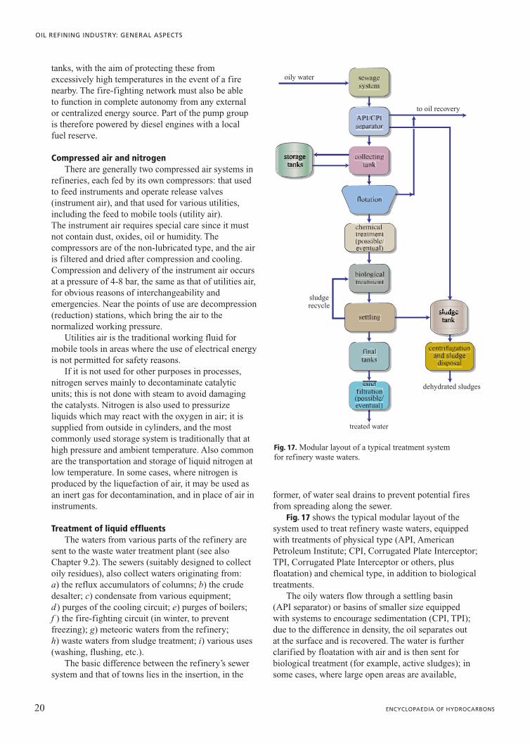
Fig. 17 shows the typical modular layout of thesystem used to treat refinery waste waters, equippedwith treatments of physical type (API, AmericanPetroleum Institute; CPI, Corrugated Plate Interceptor;TPI, Corrugated Plate Interceptor or others, plusfloatation) and chemical type, in addition to biologicaltreatments.
The oily waters flow through a settling basin(API separator) or basins of smaller size equippedwith systems to encourage sedimentation (CPI, TPI);due to the difference in density, the oil separates outat the surface and is recovered. The water is furtherclarified by floatation with air and is then sent forbiological treatment (for example, active sludges); insome cases, where large open areas are available,
20 ENCYCLOPAEDIA OF HYDROCARBONS
OIL REFINING INDUSTRY: GENERAL ASPECTS
treated water
oily water
to oil recovery
sludgerecycle
dehydrated sludges
Fig. 17. Modular layout of a typical treatment system for refinery waste waters.

lagooning may also be used. Chemical treatment(pH regulation, addition of FeCl2, etc.) may benecessary to condition the water before it is sent tothe biological plant.
The plant is designed for peak flow rates; however,these may not take account of unusually heavy rain.Large basins and/or accumulation tanks are thereforeneeded to stagger the intake to the treatment plant inthese cases.
The diagram in Fig. 17 does not include the unitknown as a sour water stripper, which is normallyindependent. This unit consists of a stripping column,heated with steam, which receives the streams rich inH2S and NH3 produced by distillation, hydrocracking,hydrodesulphurization, gas treatment, amineregeneration, sulphur and coking units. The vapoursreleased at the top of the stripping columns are sent tothe sulphur plant.
Distribution of fuelsOn average, 4-8% of the crude oil is used to run
the refinery. The most frequently used fuels are fueloil and refinery fuel gas; auxiliary fuels may benatural gas, acquired from outside, and coke if therefinery has a coking unit.
Refinery fuel gas consists of all the light components(H2, CH4, C2H6, H2S, etc) separated in the overheadaccumulators of the various columns; these componentsare partly contained within crude oil, but derive mainlyfrom secondary pyrolysis and cracking processes.
Fuel oil is the residue from various treatments;refineries tend to use the more viscous oil with a lowercommercial value, given its high content inasphaltenes and heteroatoms (sulphur).
Normally the burners in refinery furnaces aredesigned to burn both gas and oil. Natural gas isused if there is a lack of the aforementionedfuels, or more frequently due to environmentalproblems.
The feed circuit for the oil includes one or morepurpose-built tanks, pumps, and the various controlsystems. The gas circuit may also include a store ofLPG, which intervenes if there are variations in theflow rates and/or the calorific value of the refinerygas. As such, for example, it is not always possibleto replace refinery gas directly and fully withmethane (whose calorific value and density arefairly different) without influencing the performanceof the furnaces. Fig. 18 shows a diagram of thedistribution of fuel gas in a refinery with a LPGstorage facility.
Flare and blow-down systemThe appliances belonging to the various units,
designed to resist given pressures, are protectedagainst potential overpressures by release valves. Thedischarges from these valves are sent to the flare,generally consisting of a vertical tube of sufficientheight, equipped at its base with a water seal(to prevent air re-entering) and at the top by a pilot
21VOLUME II / REFINING AND PETROCHEMICALS
STRUCTURES AND SCHEMES
propane
butane
LPGstorage
tank
LPG vaporizer
fuel gasbalance drum
to flare
to flare
to process
to utility
steam
condensate
refinery fuel gas
Fig. 18. System to distribute refinery fuel gas.

burner that is always on, and triggers the combustionof the discharged hydrocarbons.
Sending in a controlled amount of steam helps toreduce the amount of smoke, and improves thedispersion of combustion products; however, steamincreases the noise levels of the flare.
The flare thus represents a practical and safesystem for controlling the irregular intake ofhydrocarbon vapours, both in emergencies, andwhen discharges occur from the numerous reliefvalves.
By burning the vapours emitted accidentally, directdischarges into the atmosphere are avoided whichwould otherwise cause safety and environmentalproblems. A careful management of processes,however, must avoid an excess of hydrocarbons beingsent to the flare, to limit problems of thermalirradiation, luminance, smoke and noise.
In the intake manifold to the flare there is aseparation drum for liquids to collect any (accidental)liquid condensation, so as to avoid this reaching thewater seal.
So-called smokeless flares work on the principle ofincreasing the turbulence of fuel gases and air, withthe potential help of steam, in order to improveblending and keep the formation of soot to aminimum.
Ground flares are only a few metres high and arevery large in diameter; the absence of smoke isobtained without using steam in order to decreasenoise levels. A further reduction in noise levels isobtained by subdividing the flame into numeroussmall burners and by using acoustic absorptionsystems. The cost of these appliances is higher thanthose for traditional flares; this is also true ofoperating costs. In all cases, the flare is located at adistance from the process units for safety reasons.
Fig. 19 shows a typical blow-down system withboth a ground flare and traditional flare; the lattercomes into operation if there are overloads in theground flare.
1.1.6 Off sites
The expression off sites is normally used to describeall those structures used for the reception, storage anddelivery of refinery products. Considering the size ofthe tank farm, the off sites represent, logistically aswell, an extremely important part of the refinery, andensure: a) the reception and storage of raw materials;b) the necessary feedstock for process units; c) thereception of products from the units; d) thepreparation, storage and delivery of finished products.
22 ENCYCLOPAEDIA OF HYDROCARBONS
OIL REFINING INDUSTRY: GENERAL ASPECTS
flare gas header
radiationsensor
pilotsignitortubes
compressedair
ignitiongas
pilotgas
flame frontignition control
ground flare
groundflarewaterseal
elevated flarewater seal
cyclonic or gravitydisentrainment drum
steam
from manual vents
from reliefvalves
waste gasesfrom units
purge gas
Fig. 19. Blow-down system equipped with elevated flare and ground flare (Parkash, 2003).

The products from treatment plants are almostalways intermediate products, and become commercialproducts only after blending and any additivationrequired. These are received in component tanks, andare then transferred to delivery tanks, in which theproducts are blended according to specificformulations.
TanksFrom an engineering point of view, tanks can be
classified into various types which will be brieflylisted below.
Tanks for products with low vapour pressure. Theseare used for residual fuel oils or distillates (up to gasoil) and for bitumens. They are cylindrical verticaltanks, in welded steel plate, with a fixed conical roof.They are grouped inside collective containment basins.They usually have heating coils on the bottom and, forthe most viscous products (for example bitumens), arecompletely insulated on all exposed surfaces. Thosewith bare surfaces have water sprinkler devices foremergency cooling.
Tanks for products with medium vapour pressure.These are used for crude oil and light distillates. Theyare cylindrical tanks with floating roofs which preventthe formation of pockets of gas and air above theliquid. The bottom, roof and cylindrical shell are madeof rolled and welded steel plates. The floating roof hasfor some time been the most effective, practical andeconomical system to contain evaporation losses. Thetanks used for crude oil can be heated if necessaryusing steam coils placed on the bottom. Each tank islocated inside a containment basin surrounded byearth banks or walls in reinforced concrete. Thevolume of the basin must be identical to that of thetank: the area of the basin is therefore much largerthan that of the tank, and determines the characteristicappearance of tank farms (see again Fig. 11). Crudeoil tanks may be extremely large (up to 160.000 m3).
Tanks for products with high vapour pressure.These tanks are used to contain, in the liquid form,products which would be gaseous under normalpressure conditions; in practice these are thehydrocarbons of propane and butane type which makeup LPGs. Traditionally, the tanks are spherical forbutane and LPG, and cylindrical for propane, capableof resisting to a pressure of a few bar. Today there is atendency always to use the cylindrical shape, small insize and with a hemispherical bottom. For safetyreasons, the current tendency is to cover these tankswith a layer of earth (‘buried’ tanks).
Preparation of finished productsAs already noted, the process units produce various
fractions which must be suitably blended in order to
obtain the properties required of finished commercialproducts. Very often, additives of various types arealso added to improve quality and differentiatebetween the various products (colorants, denaturants).In the case of lubricants, additivation is offundamental importance.
Blending systems may be of discontinuous orcontinuous in-line type. In the discontinuous (batch)system, the components of a product are added andblended in a tank. Larger modern refineries use thecontinuous in-line blending system, whichsimultaneously blends measured quantities of allcomponents and additives in the pipeline; the accuracyis such that the product formed conforms tospecifications at all times, and can be drawn off theline directly.
Transportation of productsCrude oil and the finished products are transported
using oil pipelines, tankers, rail tank wagons andtanker lorries.
Coastal refineries are equipped with marinestructures (bridges, artificial islands) for loading andreception. Oil pipelines are effective and economicaltransportation systems which carry ‘black’ products(crude oil, fuel oil, bitumen) and ‘white’ products(gas-oils, gasolines, etc) in different pipelines.
Overland transportation may also make use oftanker lorries and/or rail tank wagons which run intothe refineries on special rail links. Where marinetransportation is used, the connection betweenmoorings and the tankers is ensured byhydropneumatic arms or flexible nozzles. Large oiltankers may moor in open waters at purpose-builtbuoys or floating artificial islands resting on theseabed.
1.1.7 Operating procedures
The type of operations and the nature of the materialstreated classify oil refineries as high risk industries(for aspects relating to safety see Chapter 9.1).Operating procedures are closely linked to the issuesof safety and product quality; they play an essentialrole in running the plants in a refinery. The termprocedures is used to refer to an ordered series ofactivities aimed at achieving a specific objective. Theincreasing complexity of chemical, petroleum andpetrochemical plants requires operators to performnumerous delicate interventions during the variousphases of a plant’s life; these tasks must be performedaccording to clearly defined sequences andmethodologies. In the case of petrochemical plants andrefineries, the sequence and nature of these activities
23VOLUME II / REFINING AND PETROCHEMICALS
STRUCTURES AND SCHEMES

are the result of best practice experience andengineering know-how. This allows for anoptimization of the operations forming the object ofthe procedure, to ensure safety, the quality ofoperations and the economic viability of thecompany’s management. Safety is certainly the mostsignificant outcome of the application of operatingprocedures.
In refineries, written procedures are drawn up andapplied, this provides precise instructions for the safeexecution of the activities required by the process.These procedures must cover all principal operatingsituations (initial start-up; normal run; temporary shut-down; emergency shut-down, with the indicationof the type of emergency; emergency operations;normal shut-down; start-up following maintenance andafter emergency shut-down), and take account of bothoperating limitations (consequences of a deviation fromnormal operation; interventions required to correct oravoid deviation) and of safety and environmentalhygiene (properties and hazards of the chemicalproducts used in the plants; necessary precautions toprevent exposure; measures to be taken in the event ofcontact or inhalation; quality control for raw materials;control of storage levels of hazardous chemicalsubstances; other special or exceptional hazards).
The operating procedures must be easily accessibleto staff working in the plants and in maintenance, andmust be reviewed with sufficient frequency to ensurethat they correspond to the operations actually carriedout, taking account of any modifications to processes,appliances and facilities in the plant. Specifically, inrefineries, safety procedures for dangerous tasks mustbe drawn up and applied. These procedures must befollowed by company staff and by sub-contractors. The entry of external workers into the plant(maintenance and laboratory workers, representativesof sub-contractors, etc.) must be regulated.
The plant manual mentions these activities, butdoes not normally explain them in an analytical way;
at times it is assumed that they are well-known.It is therefore necessary for these to formthe first step in the education and trainingprogramme for staff. It is also necessary to draw upa complete list of these, to avoid dangerousomissions.
The procedures are set down in specialmanuals, known as operating manuals, issued byprocess and engineering companies incollaboration with the management of the refinerywhich is to use them. In addition, themanufacturers and suppliers of appliances alsoproduce specific manuals.
References
Aalund L.R. (1977) Competition sparks refinery progress,«Oil & Gas Journal», 75th Anniversary Issue, August, 339.
Giavarini C. (1989) L’industria della raffinazione del petrolio.Le origini e lo sviluppo, «La Chimica e l’Industria», 71,12.
Giavarini C. (1990) Gli anni del piombo, «La Chimica el’Industria», 72, 1027.
Giavarini C. (1993) L’industria della raffinazione del petrolio.Ambiente e innovazione tecnologica nello sviluppo attuale,«La Rivista dei Combustibili», 47, 16.
Iadanza P. (2004) Per la ‘dieselizzazione’generalizzata degliautoveicoli, «La Rivista dei Combustibili», 58, 60-66.
Parkash S. (2003) Refining processes handbook, Amsterdam-London, Gulf.
Rumbold C. (1971) Raffinazione, in: Eni (1962-1971)Enciclopedia del petrolio e del gas naturale, Milano,Colombo, 8v.; v. VIII, 372.
Swaty T.E. (2005) Global refining industry trends. The presentand future, «Hydrocarbon Processing», September, 35-44.
Carlo GiavariniDipartimento di Ingegneria Chimica, dei Materiali,
delle Materie Prime e MetallurgiaUniversità degli Studi di Roma ‘La Sapienza’
Roma, Italy
24 ENCYCLOPAEDIA OF HYDROCARBONS
OIL REFINING INDUSTRY: GENERAL ASPECTS