Embed Size (px)
Citation preview
000013791 Rev. 1.0
1
User Manual
000013791 Rev. 1.0
2
CONTENTS 1. GENERAL INTRODUCTION
2. INSTALLATION PRECAUTIONS
3. IDENTIFICATION OF COMPONENTS
4. TECHNICAL SPECIFICATIONS
5. ASSEMBLY INSTRUCTIONS 5.1 APPLICATION EXAMPLE 6. DESCRIPTION OF THE CIRCUIT
7. CALIBRATION MENU 7.1 CALIBRATION 8. PROGRAMMING
9. DOSING METHOD
10. ACTIVATIONS
11. ALARMS
12. PRE-DEFINED CONTROL PARAMETERS
13. LIST OF POSSIBLE ANOMALIES AND RELATIVE SOLUTIONS
14. HANDLING
15. STORING THE PUMP AFTER USE
WARNINGS
000013791 Rev. 1.0
3
1. GENERAL INTRODUCTION The Pool Basic Pro EVO control method belongs to a new line of instruments carefully developed by the supplier for the innovative management of pools. This device is easy to use and permits continuous control of the pH. The peristaltic pumps have a 1,5 l/h flow rate for pH regulation and have a pressurised injection flow rate up to 1.5 bar. This easy-to-use instrument does not require special maintenance operations. It is equipped with a self-regulation procedure and automatic control of the electrode’s state.
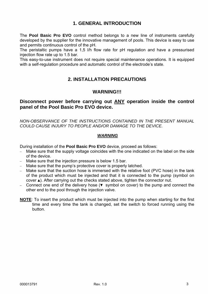
2. INSTALLATION PRECAUTIONS
WARNING!!! Disconnect power before carrying out ANY operation inside the control panel of the Pool Basic Pro EVO device. NON-OBSERVANCE OF THE INSTRUCTIONS CONTAINED IN THE PRESENT MANUAL COULD CAUSE INJURY TO PEOPLE AND/OR DAMAGE TO THE DEVICE.
WARNING During installation of the Pool Basic Pro EVO device, proceed as follows: − Make sure that the supply voltage coincides with the one indicated on the label on the side
of the device. − Make sure that the injection pressure is below 1.5 bar. − Make sure that the pump’s protective cover is properly latched. − Make sure that the suction hose is immersed with the relative foot (PVC hose) in the tank
of the product which must be injected and that it is connected to the pump (symbol on cover ). After carrying out the checks stated above, tighten the connector nut.
− Connect one end of the delivery hose ( symbol on cover) to the pump and connect the other end to the pool through the injection valve.
NOTE: To insert the product which must be injected into the pump when starting for the first
time and every time the tank is changed, set the switch to forced running using the button.
000013791 Rev. 1.0
4
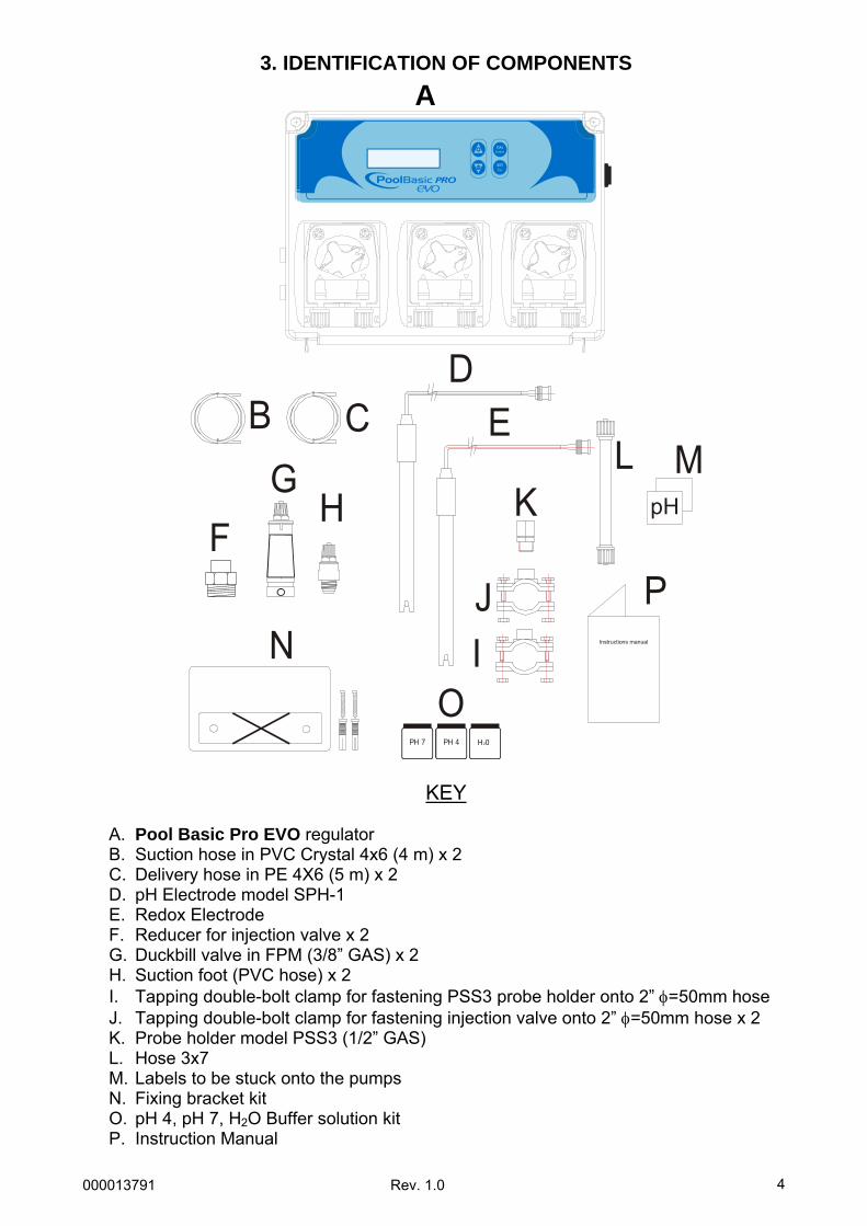
3. IDENTIFICATION OF COMPONENTS
PH 7 PH 4 H 02
B CG
H
O
FpH
Instructions manual
KM
NP
IJ
L
DE
KEY
A. Pool Basic Pro EVO regulator B. Suction hose in PVC Crystal 4x6 (4 m) x 2 C. Delivery hose in PE 4X6 (5 m) x 2 D. pH Electrode model SPH-1 E. Redox Electrode F. Reducer for injection valve x 2 G. Duckbill valve in FPM (3/8” GAS) x 2 H. Suction foot (PVC hose) x 2 I. Tapping double-bolt clamp for fastening PSS3 probe holder onto 2” φ=50mm hose J. Tapping double-bolt clamp for fastening injection valve onto 2” φ=50mm hose x 2 K. Probe holder model PSS3 (1/2” GAS) L. Hose 3x7 M. Labels to be stuck onto the pumps N. Fixing bracket kit O. pH 4, pH 7, H2O Buffer solution kit P. Instruction Manual
A
000013791 Rev. 1.0
5
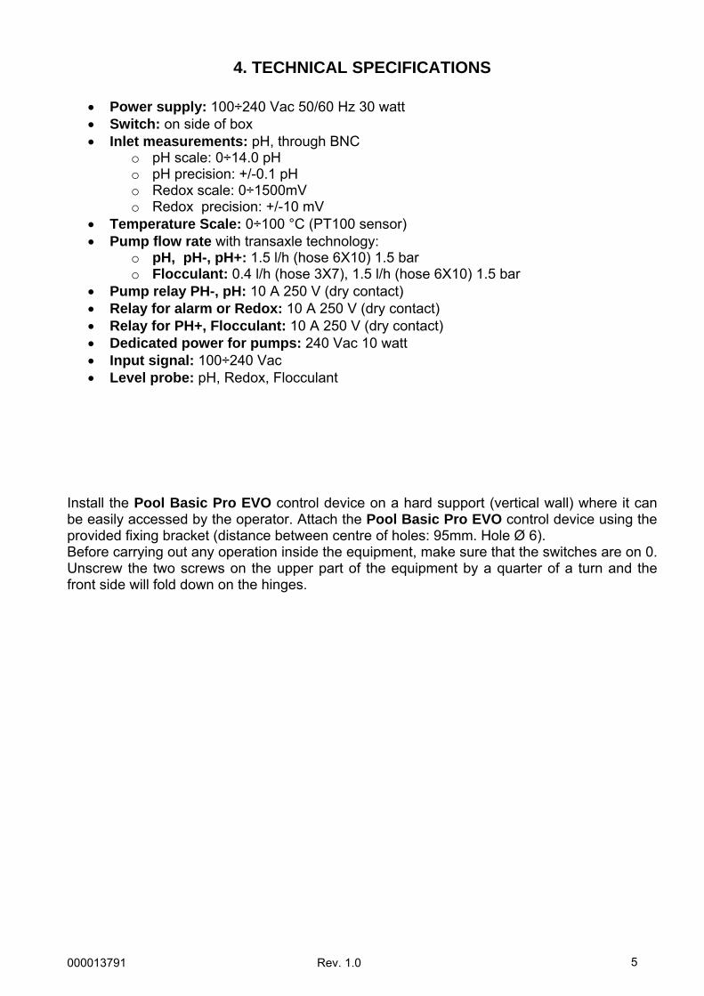
4. TECHNICAL SPECIFICATIONS
• Power supply: 100÷240 Vac 50/60 Hz 30 watt • Switch: on side of box • Inlet measurements: pH, through BNC
o pH scale: 0÷14.0 pH o pH precision: +/-0.1 pH o Redox scale: 0÷1500mV o Redox precision: +/-10 mV
• Temperature Scale: 0÷100 °C (PT100 sensor) • Pump flow rate with transaxle technology:
o pH, pH-, pH+: 1.5 l/h (hose 6X10) 1.5 bar o Flocculant: 0.4 l/h (hose 3X7), 1.5 l/h (hose 6X10) 1.5 bar
• Pump relay PH-, pH: 10 A 250 V (dry contact) • Relay for alarm or Redox: 10 A 250 V (dry contact) • Relay for PH+, Flocculant: 10 A 250 V (dry contact) • Dedicated power for pumps: 240 Vac 10 watt • Input signal: 100÷240 Vac • Level probe: pH, Redox, Flocculant
Install the Pool Basic Pro EVO control device on a hard support (vertical wall) where it can be easily accessed by the operator. Attach the Pool Basic Pro EVO control device using the provided fixing bracket (distance between centre of holes: 95mm. Hole Ø 6). Before carrying out any operation inside the equipment, make sure that the switches are on 0. Unscrew the two screws on the upper part of the equipment by a quarter of a turn and the front side will fold down on the hinges.
000013791 Rev. 1.0
6
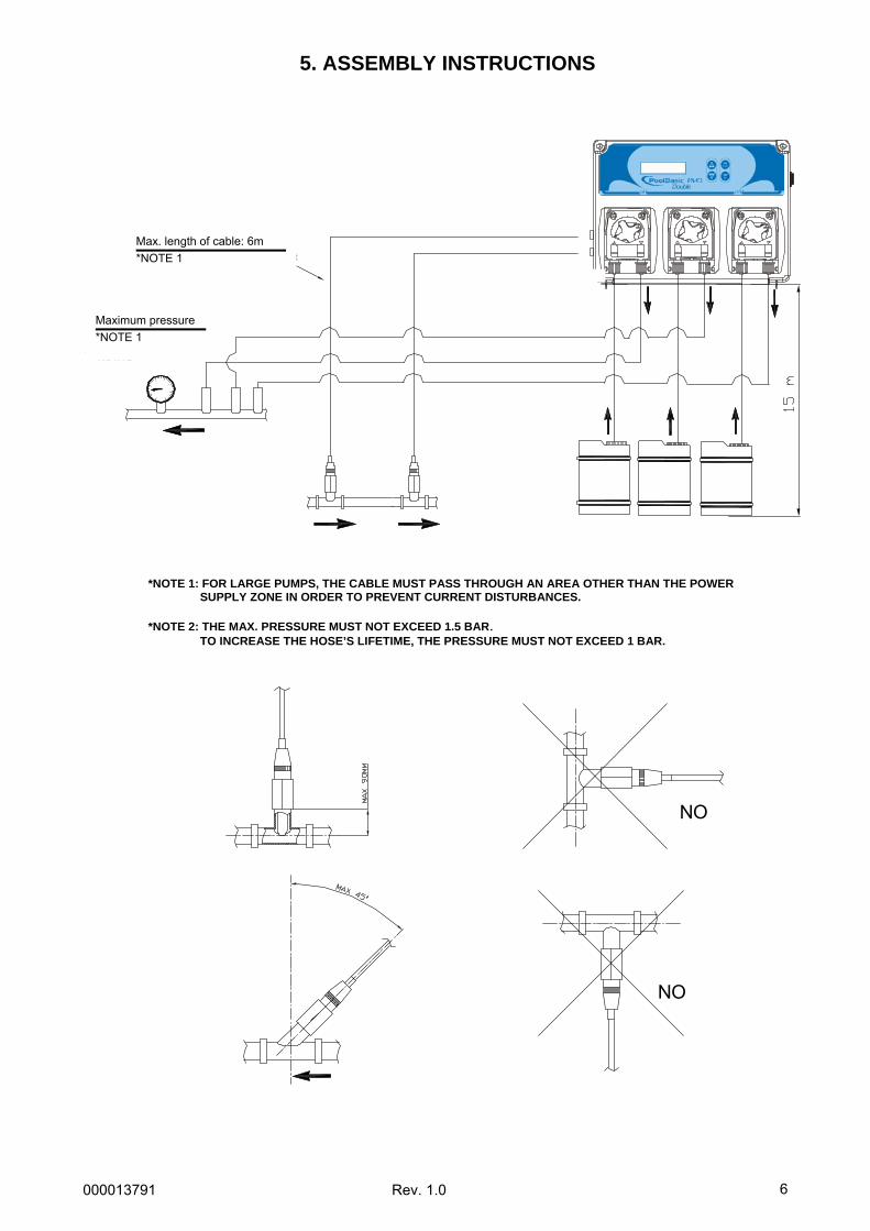
5. ASSEMBLY INSTRUCTIONS
NO
NO
* NOTA 2: LA PRESSIONE MAX. NON DEVE ESSERE SUPERIORE A 1,5 BAR. PER AUMENTARE LA DURATA DEL TUBO, LA PRESSIONE NON DEVE SUPERARE 1 BAR.
* NOTA 1: IL CAVO DEVE PASSARE IN UNA ZONA DIVERSA DA QUELLA DI ALIMENTAZIONE PER POMPE GROSSE, PER EVITARE DISTURBI DI CORRENTE.
3
1
25
4
6
0 7
Lunghezza massima de cavo: 6 mt
Pressione Massima: 1,5 bar* NOTA 2
* NOTA 1
*NOTE 1: FOR LARGE PUMPS, THE CABLE MUST PASS THROUGH AN AREA OTHER THAN THE POWER SUPPLY ZONE IN ORDER TO PREVENT CURRENT DISTURBANCES.
*NOTE 2: THE MAX. PRESSURE MUST NOT EXCEED 1.5 BAR.
TO INCREASE THE HOSE’S LIFETIME, THE PRESSURE MUST NOT EXCEED 1 BAR.
Max. length of cable: 6m *NOTE 1
Maximum pressure *NOTE 1
000013791 Rev. 1.0
7
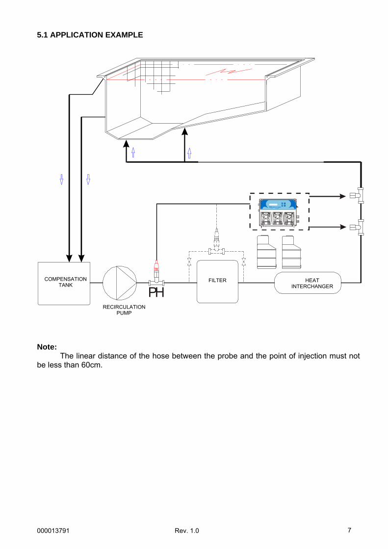
5.1 APPLICATION EXAMPLE
PH Note: The linear distance of the hose between the probe and the point of injection must not be less than 60cm.
COMPENSATION TANK
RECIRCULATION PUMP
FILTER HEAT INTERCHANGER
000013791 Rev. 1.0
8
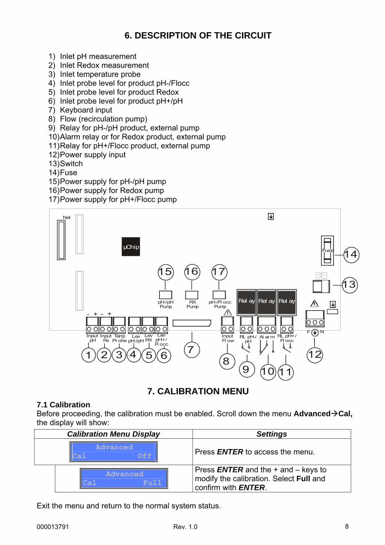
6. DESCRIPTION OF THE CIRCUIT
1) Inlet pH measurement 2) Inlet Redox measurement 3) Inlet temperature probe 4) Inlet probe level for product pH-/Flocc 5) Inlet probe level for product Redox 6) Inlet probe level for product pH+/pH 7) Keyboard input 8) Flow (recirculation pump) 9) Relay for pH-/pH product, external pump 10) Alarm relay or for Redox product, external pump 11) Relay for pH+/Flocc product, external pump 12) Power supply input 13) Switch 14) Fuse 15) Power supply for pH-/pH pump 16) Power supply for Redox pump 17) Power supply for pH+/Flocc pump
7. CALIBRATION MENU 7.1 Calibration Before proceeding, the calibration must be enabled. Scroll down the menu Advanced Cal, the display will show:
Exit the menu and return to the normal system status.
Calibration Menu Display Settings
Advanced Cal Off
Press ENTER to access the menu.
Advanced Cal Full
Press ENTER and the + and – keys to modify the calibration. Select Full and confirm with ENTER.
Al armRL pH-/pH
InputFl ow
RL pH+/Fl occ
F NLev
pH+/Fl occ
Net
FuseµChip
Rel ay Rel ay Rel ay
1 2 78
9 10 11
12
14
16 17
LevRX
LevpH-/pH
TempProbe
InputRx
InputpH
3 4 5 6
13
pH-/pHPump
15
pH-/Fl occ
Pump
RX
Pump
- + - +
000013791 Rev. 1.0
9
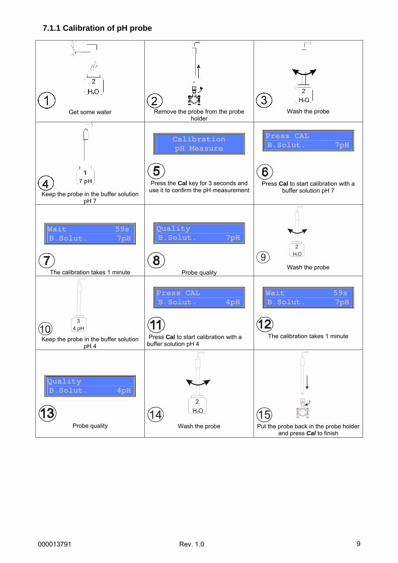
7.1.1 Calibration of pH probe
Get some water
Remove the probe from the probe
holder
Wash the probe
Keep the probe in the buffer solution
pH 7
Press the Cal key for 3 seconds and
use it to confirm the pH measurement
Calibration pH Measure
Press Cal to start calibration with a
buffer solution pH 7
Press CAL B.Solut. 7pH
The calibration takes 1 minute
Wait 59s B.Solut. 7pH
Probe quality
Quality B.Solut. 7pH
H O2
2
9 Wash the probe
4 pH3
10 Keep the probe in the buffer solution
pH 4
Press Cal to start calibration with a buffer solution pH 4
Press CAL B.Solut. 4pH
The calibration takes 1 minute
Wait 59sB.Solut. 7pH
Probe quality
Quality B.Solut. 4pH
H O2
2
14 Wash the probe
15 Put the probe back in the probe holder
and press Cal to finish
000013791 Rev. 1.0
10
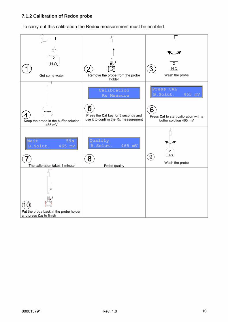
7.1.2 Calibration of Redox probe To carry out this calibration the Redox measurement must be enabled.
Get some water
Remove the probe from the probe
holder
Wash the probe
Keep the probe in the buffer solution
465 mV
Press the Cal key for 3 seconds and use it to confirm the Rx measurement
Calibration Rx Measure
Press Cal to start calibration with a
buffer solution 465 mV
Press CAL B.Solut. 465 mV
The calibration takes 1 minute
Wait 59s B.Solut. 465 mV
Probe quality
Quality B.Solut. 465 mV
H O2
2
9 Wash the probe
10 Put the probe back in the probe holder and press Cal to finish
000013791 Rev. 1.0
11
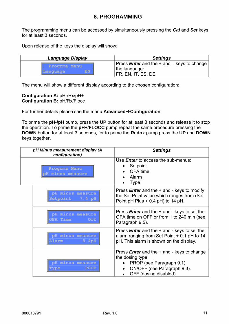
8. PROGRAMMING The programming menu can be accessed by simultaneously pressing the Cal and Set keys for at least 3 seconds. Upon release of the keys the display will show:
The menu will show a different display according to the chosen configuration: Configuration A: pH-/Rx/pH+ Configuration B: pH/Rx/Flocc For further details please see the menu Advanced Configuration To prime the pH-/pH pump, press the UP button for at least 3 seconds and release it to stop the operation. To prime the pH+/FLOCC pump repeat the same procedure pressing the DOWN button for at least 3 seconds, for to prime the Redox pump press the UP and DOWN keys together.
Language Display Settings
Progrma Menu Language EN
Press Enter and the + and – keys to change the language: FR, EN, IT, ES, DE
pH Minus measurement display (A configuration)
Settings
Progrma Menu pH minus measure
Use Enter to access the sub-menus: • Setpoint • OFA time • Alarm • Type
pH minus measureSetpoint 7.4 pH
Press Enter and the + and - keys to modify the Set Point value which ranges from (Set Point pH Plus + 0.4 pH) to 14 pH.
pH minus measureOFA Time Off
Press Enter and the + and - keys to set the OFA time on OFF or from 1 to 240 min (see Paragraph 9.5).
pH minus measureAlarm 8.4pH
Press Enter and the + and - keys to set the alarm ranging from Set Point + 0.1 pH to 14 pH. This alarm is shown on the display.
pH minus measureType PROP
Press Enter and the + and - keys to change the dosing type.
• PROP (see Paragraph 9.1). • ON/OFF (see Paragraph 9.3). • OFF (dosing disabled)
000013791 Rev. 1.0
12
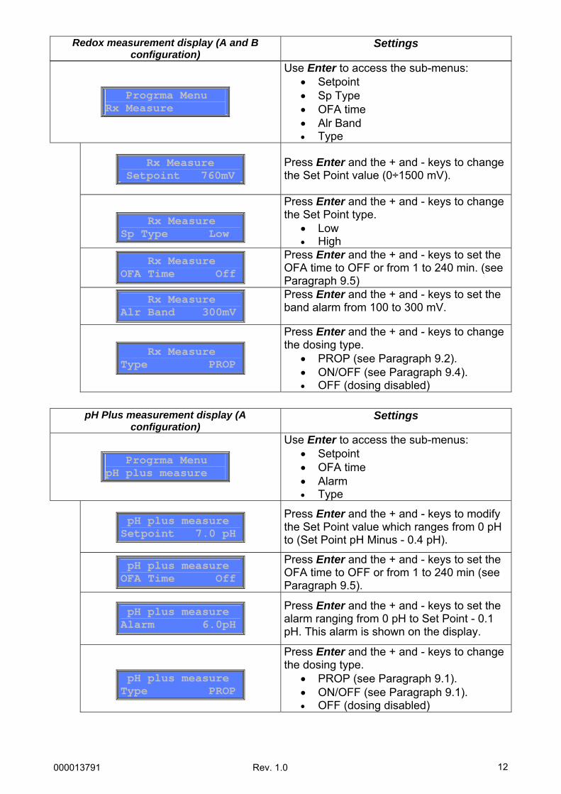
Progrma Menu Rx Measure
Use Enter to access the sub-menus: • Setpoint • Sp Type • OFA time • Alr Band • Type
Rx Measure Setpoint 760mV
Press Enter and the + and - keys to change the Set Point value (0÷1500 mV).
Rx Measure Sp Type Low
Press Enter and the + and - keys to change the Set Point type.
• Low • High
Rx Measure OFA Time Off
Press Enter and the + and - keys to set the OFA time to OFF or from 1 to 240 min. (see Paragraph 9.5)
Rx Measure Alr Band 300mV
Press Enter and the + and - keys to set the band alarm from 100 to 300 mV.
Rx Measure Type PROP
Press Enter and the + and - keys to change the dosing type.
• PROP (see Paragraph 9.2). • ON/OFF (see Paragraph 9.4). • OFF (dosing disabled)
Redox measurement display (A and B configuration)
Settings
pH Plus measurement display (A configuration)
Settings
Progrma Menu pH plus measure
Use Enter to access the sub-menus: • Setpoint • OFA time • Alarm • Type
pH plus measure Setpoint 7.0 pH
Press Enter and the + and - keys to modify the Set Point value which ranges from 0 pH to (Set Point pH Minus - 0.4 pH).
pH plus measure OFA Time Off
Press Enter and the + and - keys to set the OFA time to OFF or from 1 to 240 min (see Paragraph 9.5).
pH plus measure Alarm 6.0pH
Press Enter and the + and - keys to set the alarm ranging from 0 pH to Set Point - 0.1 pH. This alarm is shown on the display.
pH plus measure Type PROP
Press Enter and the + and - keys to change the dosing type.
• PROP (see Paragraph 9.1). • ON/OFF (see Paragraph 9.1). • OFF (dosing disabled)
000013791 Rev. 1.0
13
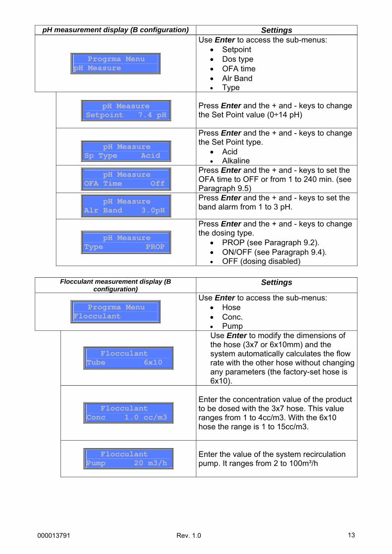
Progrma Menu pH Measure
Use Enter to access the sub-menus: • Setpoint • Dos type • OFA time • Alr Band • Type
pH Measure Setpoint 7.4 pH
Press Enter and the + and - keys to change the Set Point value (0÷14 pH)
pH Measure Sp Type Acid
Press Enter and the + and - keys to change the Set Point type.
• Acid • Alkaline
pH Measure OFA Time Off
Press Enter and the + and - keys to set the OFA time to OFF or from 1 to 240 min. (see Paragraph 9.5)
pH Measure Alr Band 3.0pH
Press Enter and the + and - keys to set the band alarm from 1 to 3 pH.
pH Measure Type PROP
Press Enter and the + and - keys to change the dosing type.
• PROP (see Paragraph 9.2). • ON/OFF (see Paragraph 9.4). • OFF (dosing disabled)
pH measurement display (B configuration) Settings
Flocculant measurement display (B configuration)
Settings
Progrma Menu Flocculant
Use Enter to access the sub-menus: • Hose • Conc. • Pump
Flocculant Tube 6x10
Use Enter to modify the dimensions of the hose (3x7 or 6x10mm) and the system automatically calculates the flow rate with the other hose without changing any parameters (the factory-set hose is 6x10).
Flocculant Conc 1.0 cc/m3
Enter the concentration value of the product to be dosed with the 3x7 hose. This value ranges from 1 to 4cc/m3. With the 6x10 hose the range is 1 to 15cc/m3.
Flocculant Pump 20 m3/h
Enter the value of the system recirculation pump. It ranges from 2 to 100m³/h
000013791 Rev. 1.0
14
Press Esc to exit any menu and confirm the settings by pressing Enter.
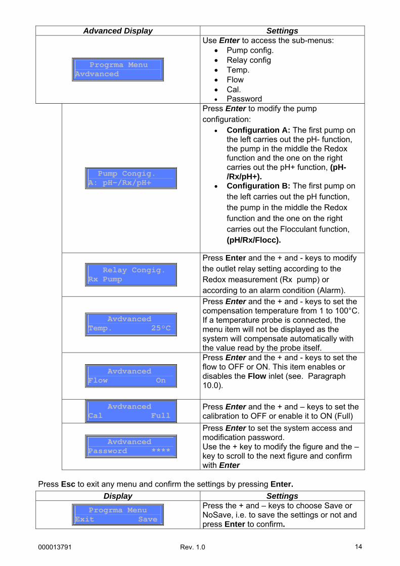
Advanced Display Settings
Progrma Menu Avdvanced
Use Enter to access the sub-menus: • Pump config. • Relay config • Temp. • Flow • Cal. • Password
Pump Congig. A: pH-/Rx/pH+
Press Enter to modify the pump configuration:
• Configuration A: The first pump on the left carries out the pH- function, the pump in the middle the Redox function and the one on the right carries out the pH+ function, (pH-/Rx/pH+).
• Configuration B: The first pump on the left carries out the pH function, the pump in the middle the Redox function and the one on the right carries out the Flocculant function, (pH/Rx/Flocc).
Relay Congig. Rx Pump
Press Enter and the + and - keys to modify the outlet relay setting according to the Redox measurement (Rx pump) or according to an alarm condition (Alarm).
Avdvanced Temp. 25°C
Press Enter and the + and - keys to set the compensation temperature from 1 to 100°C. If a temperature probe is connected, the menu item will not be displayed as the system will compensate automatically with the value read by the probe itself.
Avdvanced Flow On
Press Enter and the + and - keys to set the flow to OFF or ON. This item enables or disables the Flow inlet (see. Paragraph 10.0).
Avdvanced Cal Full
Press Enter and the + and – keys to set the calibration to OFF or enable it to ON (Full)
Avdvanced Password ****
Press Enter to set the system access and modification password. Use the + key to modify the figure and the – key to scroll to the next figure and confirm with Enter
Display Settings
Progrma Menu Exit Save
Press the + and – keys to choose Save or NoSave, i.e. to save the settings or not and press Enter to confirm.
000013791 Rev. 1.0
15
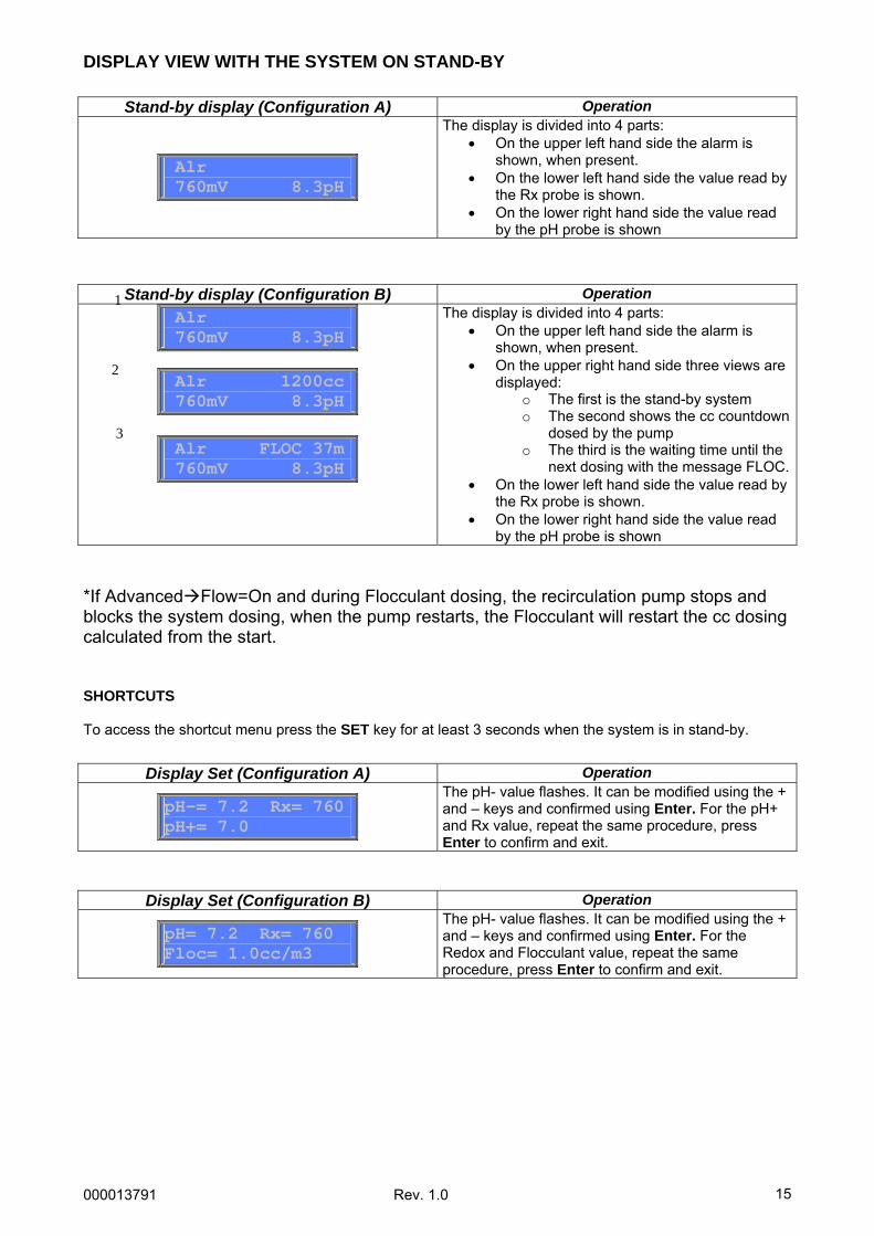
DISPLAY VIEW WITH THE SYSTEM ON STAND-BY
*If Advanced Flow=On and during Flocculant dosing, the recirculation pump stops and blocks the system dosing, when the pump restarts, the Flocculant will restart the cc dosing calculated from the start. SHORTCUTS To access the shortcut menu press the SET key for at least 3 seconds when the system is in stand-by.
Stand-by display (Configuration A) Operation
Alr 760mV 8.3pH
The display is divided into 4 parts: • On the upper left hand side the alarm is
shown, when present. • On the lower left hand side the value read by
the Rx probe is shown. • On the lower right hand side the value read
by the pH probe is shown
Stand-by display (Configuration B) Operation Alr 760mV 8.3pH
Alr 1200cc 760mV 8.3pH
Alr FLOC 37m 760mV 8.3pH
The display is divided into 4 parts: • On the upper left hand side the alarm is
shown, when present. • On the upper right hand side three views are
displayed: o The first is the stand-by system o The second shows the cc countdown
dosed by the pump o The third is the waiting time until the
next dosing with the message FLOC.• On the lower left hand side the value read by
the Rx probe is shown. • On the lower right hand side the value read
by the pH probe is shown
Display Set (Configuration A) Operation
pH-= 7.2 Rx= 760 pH+= 7.0
The pH- value flashes. It can be modified using the + and – keys and confirmed using Enter. For the pH+ and Rx value, repeat the same procedure, press Enter to confirm and exit.
Display Set (Configuration B) Operation
pH= 7.2 Rx= 760 Floc= 1.0cc/m3
The pH- value flashes. It can be modified using the + and – keys and confirmed using Enter. For the Redox and Flocculant value, repeat the same procedure, press Enter to confirm and exit.
1
2
3
000013791 Rev. 1.0
16
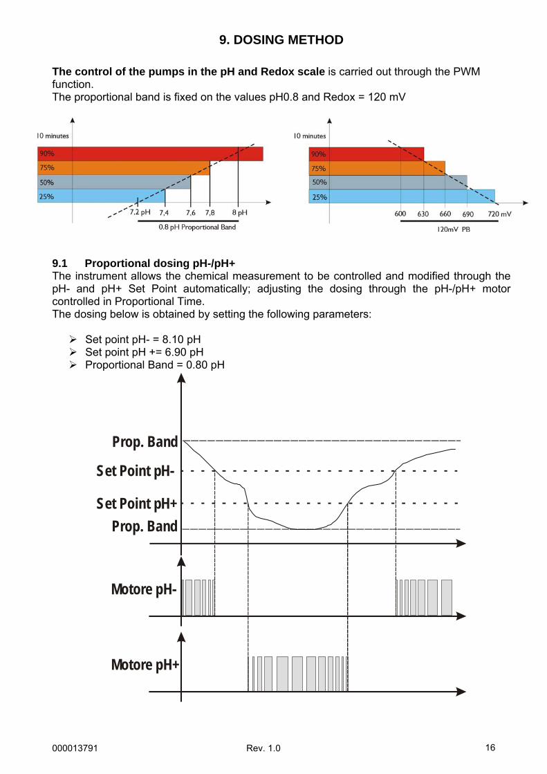
9. DOSING METHOD
The control of the pumps in the pH and Redox scale is carried out through the PWM function. The proportional band is fixed on the values pH0.8 and Redox = 120 mV 9.1 Proportional dosing pH-/pH+ The instrument allows the chemical measurement to be controlled and modified through the pH- and pH+ Set Point automatically; adjusting the dosing through the pH-/pH+ motor controlled in Proportional Time. The dosing below is obtained by setting the following parameters:
Set point pH- = 8.10 pH Set point pH += 6.90 pH Proportional Band = 0.80 pH
Set Point pH+Prop. Band
Motore pH-
Set Point pH-
Motore pH+
Prop. Band
000013791 Rev. 1.0
17
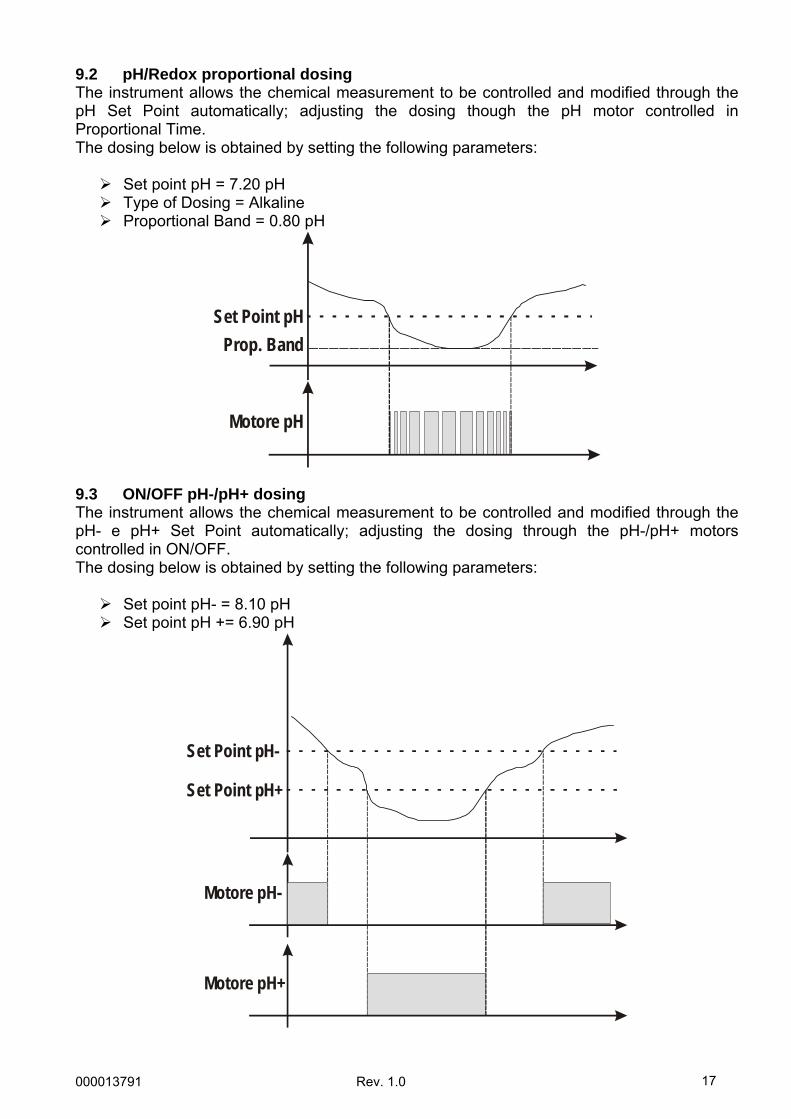
9.2 pH/Redox proportional dosing The instrument allows the chemical measurement to be controlled and modified through the pH Set Point automatically; adjusting the dosing though the pH motor controlled in Proportional Time. The dosing below is obtained by setting the following parameters:
Set point pH = 7.20 pH Type of Dosing = Alkaline Proportional Band = 0.80 pH
Set Point pHProp. Band
Motore pH
9.3 ON/OFF pH-/pH+ dosing The instrument allows the chemical measurement to be controlled and modified through the pH- e pH+ Set Point automatically; adjusting the dosing through the pH-/pH+ motors controlled in ON/OFF. The dosing below is obtained by setting the following parameters:
Set point pH- = 8.10 pH Set point pH += 6.90 pH
Set Point pH+
Motore pH-
Set Point pH-
Motore pH+
000013791 Rev. 1.0
18
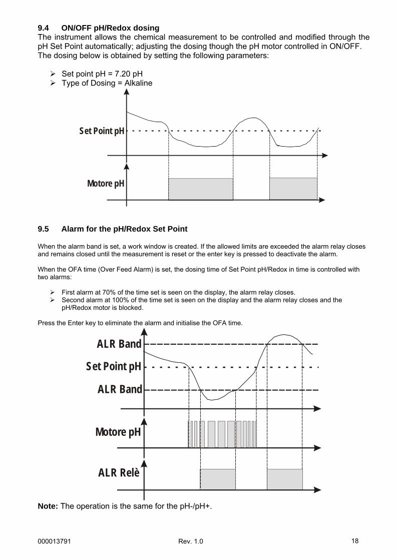
9.4 ON/OFF pH/Redox dosing The instrument allows the chemical measurement to be controlled and modified through the pH Set Point automatically; adjusting the dosing though the pH motor controlled in ON/OFF. The dosing below is obtained by setting the following parameters:
Set point pH = 7.20 pH Type of Dosing = Alkaline
Set Point pH
Motore pH
9.5 Alarm for the pH/Redox Set Point When the alarm band is set, a work window is created. If the allowed limits are exceeded the alarm relay closes and remains closed until the measurement is reset or the enter key is pressed to deactivate the alarm. When the OFA time (Over Feed Alarm) is set, the dosing time of Set Point pH/Redox in time is controlled with two alarms:
First alarm at 70% of the time set is seen on the display, the alarm relay closes. Second alarm at 100% of the time set is seen on the display and the alarm relay closes and the
pH/Redox motor is blocked. Press the Enter key to eliminate the alarm and initialise the OFA time.
Motore pH
Set Point pH
ALR Relè
ALR Band
ALR Band
Note: The operation is the same for the pH-/pH+.
000013791 Rev. 1.0
19
10. ACTIVATIONS
• Flow Function Through the recirculation pump. High voltage input 100 ÷ 240 Vac, the dosing system is switched on. High voltage input is off (the recirculation pump is switched off), the dosing system shows FLOW flashing.
11. ALARMS
Lev pH-= pH product level probe alarm. Lev pH+= pH product level probe alarm. Lev pH= pH product level probe alarm. Lev Flocc= Flocculant product level probe alarm. OFA pH/Redox= Set Point not reached with the OFA time set* pH/Redox Band= Shown when the value read is outside the SetPoint of +/- the band value set.
*At 70% of the time set the system shows and activates the alarm relay, at 100% it blocks the motor. Press the Enter key to reset the alarm. Press the Enter key with the alarm active and its relay is deactivated only remaining shown on the display.
12. PRE-DEFINED CONTROL PARAMETERS
To reset default values and settings:
• Disconnect the device • Hold down the + and – keys simultaneously and connect the device • Confirm the choice to reset the default parameters
Default parameters:
• Configuration = A (pH-/Rx/pH+) • Language = UK • Set Point pH- = 7,4 pH; OFF; Alr 8,4 pH; PROP • Set Point Rx = 750mV; Low; OFF; Alr Band 300mV; PROP • Set Point pH+ = 7,0 pH; OFF; Alr 6,0 pH; PROP • Temperature = 25°C • Calibration = FULL • Flow Input= ON • Password = Disabled
000013791 Rev. 1.0
20
13. LIST OF POSSIBLE ANOMALIES AND RELATIVE SOLUTIONS
ANOMALY CAUSE SOLUTION The instrument always indicates pH 7.00
Problem with the cable and/or connector.
1) Check for possible short circuits on the electrode ↔ instrument connection cable (between the cable’s core and the external shielding). 2) Make sure that there are no traces of humidity and/or condensation on the connector of the probe or the device. 3) Make sure that 100 Ω resistance is present between terminals 11 and 12.
The electrode’s connection cable is damaged. Check the cable.
There is an air bubble in the electrode’s membrane.
Place the electrode vertically and shake it slightly until the air bubble rises. N.B.: The electrode must be vertical or tilted by a maximum of 45°.
Electrode worn. Replace the electrode.
The instrument always indicates a high or continuously unstable value
Connection cable too long or too close to an electrical wire: Disturbance.
Reduce the distance between the device and the probe. Make sure that the solution used is pH 7. Check the buffer solution pH using an electronic pH-meter.
Unsuitable buffer solution.
Use a new pH 7 buffer solution and restart calibration.
Problem on probe’s porous material, dirt deposits.
Make sure that the probe’s porous material is in good condition; wash the electrode using a diluted acid-based solution and dry with a soft cloth.
Impossible to calibrate the pH 7 value Error shown on the display Calibration quality of pH probe < 20%
Electrode worn. Replace the electrode.
Make sure that the solution used is pH 4. Check the buffer solution pH using an electronic pH-meter.
Unsuitable buffer solution.
Use a new pH 4 buffer solution and restart calibration.
Problem with the electrode bulb.
Make sure that the electrode bulb is not damaged. Make sure that it did not become dry outside of the water. As a last resort, clean the electrode and leave it immersed in the water for a few hours.
Impossible to calibrate the pH 4 value Error shown on the display Calibration quality of pH probe < 20% Electrode worn. Replace the electrode. Slow electrode response
Electrode electrostatically charged.
During the calibration phase, the electrode MUST NOT be dried with a cloth or paper; let it drip.
000013791 Rev. 1.0
21
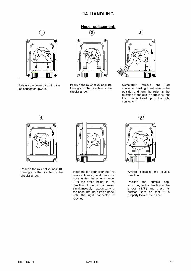
14. HANDLING
Hose replacement:
Release the cover by pulling theleft connector upward.
Position the roller at 20 past 10,turning it in the direction of thecircular arrow.
Completely release the leftconnector, holding it taut towards theoutside, and turn the roller in thedirection of the circular arrow so thatthe hose is freed up to the rightconnector.
Position the roller at 20 past 10,turning it in the direction of thecircular arrow.
Insert the left connector into therelative housing and pass thehose under the roller’s guide.Turn the probe holder in thedirection of the circular arrow,simultaneously accompanyingthe hose into the pump’s head,until the right connector isreached.
Arrows indicating the liquid’sdirection Position the pump’s cap,according to the direction of thearrows () and press itssurface hard so that it isproperly locked into place.
000013791 Rev. 1.0
22
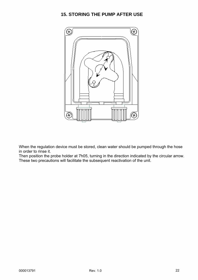
15. STORING THE PUMP AFTER USE
When the regulation device must be stored, clean water should be pumped through the hose in order to rinse it. Then position the probe holder at 7h05, turning in the direction indicated by the circular arrow. These two precautions will facilitate the subsequent reactivation of the unit.
000013791 Rev. 1.0
23
WARNINGS PRODUCTS TO BE USED: • pH Reduction: product with a sulphuric acid base, easily found on the market.
• pH Increase: product with an alkaline acid base
PRODUCTS NOT RECOMMENDED • Do not use hydrochloric acid.
Ask the installer about all other products. PROBE WARNINGS • Handle the probe with CARE. • DO NOT INSERT AN EXCESSIVE AMOUNT of chemical product prior to the probe. • Storing the probe: Extract the pH probe from the relative probe holder. Store it in the
original bottle filled with tap water. If necessary, close the probe holder using a plug the size of a 5 euro cent coin.
Since the pH electrode consists of glass parts, handle it with care. All of our electrodes are tested on the production line before being packaged. Repairs of electrodes are not foreseen by the warranty unless they do not function when they are activated for the first time. Packaging not included. In this case, in order for the probe to be accepted for examination, it absolutely must be sent in the original packaging with the relative bottle filled with water.
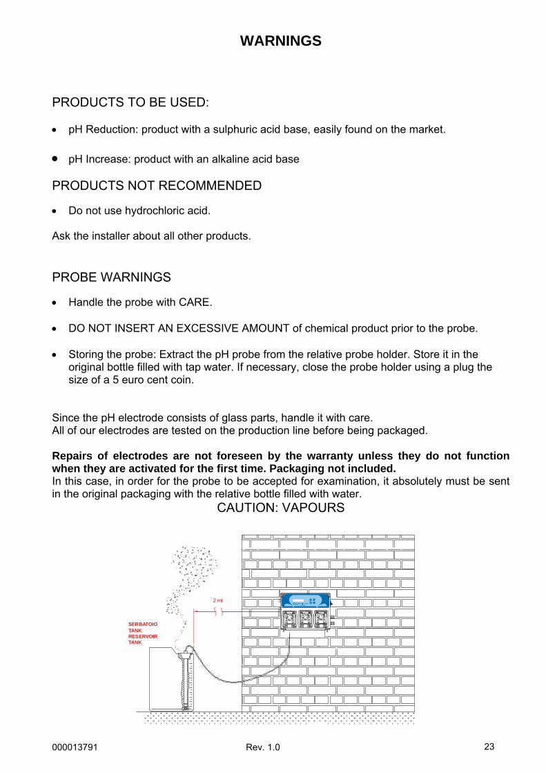
CAUTION: VAPOURS
SERBATOIOTANKRESERVOIRTANK
2 mt
![PH = - log [H 3 O + ] [H 3 O + ] = 10 - pH mol/L For pure water at 25 o C pH = - log (1.0 x 10 -7 ) = 7.00 For a change in pH by 1, H 3 O + concentration](https://img.pdfslide.us/doc/110x75/56649d4c5503460f94a29c0c/ph-log-h-3-o-h-3-o-10-ph-moll-for-pure-water-at-25-o-c-ph.jpg)


![Soil ecology and pH [Bayan Ulgii, Mongolia SAEL training 2011] v.1.0](https://img.pdfslide.us/doc/110x75/54c3362d4a79595c528b45a7/soil-ecology-and-ph-bayan-ulgii-mongolia-sael-training-2011-v10.jpg)

