Embed Size (px)
Citation preview
A Subsidiary of
0
000
Most Widely Accepted and Trusted
ICC-ES Report ESR-3713 Issued 07/2015
This report is subject to renewal 07/2016.
ICC-ES | (800) 423-6587 | (562) 699-0543 | www.icc-es.org
ICC-ES Evaluation Reports are not to be construed as representing aesthetics or any other attributes not specifically addressed, nor are they to be construed as an endorsement of the subject of the report or a recommendation for its use. There is no warranty by ICC Evaluation Service, LLC, express or implied, as to any finding or other matter in this report, or as to any product covered by the report.
Copyright © 2015
“2014 Recipient of Prestigious Western States Seismic Policy Council (WSSPC) Award in Excellence”
Look for the trusted marks of Conformity!
DIVISION: 03 00 00—CONCRETE SECTION: 03 15 19—CAST-IN CONCRETE ANCHORS
SECTION: 03 16 00—CONCRETE ANCHORS
REPORT HOLDER:
HILTI, INC.
7250 DALLAS PARKWAY, SUITE 1000 PLANO, TEXAS 75024
EVALUATION SUBJECT:
HILTI HCI-WF AND HCI-MD HEADED CAST-IN SPECIALTY INSERTS IN CRACKED AND UNCRACKED CONCRETE
ICC-ES Evaluation Reports are not to be construed as representing aesthetics or any other attributes not specifically addressed, nor are they to be construed as an endorsement of the subject of the report or a recommendation for its use. There is no warranty by ICC Evaluation Service, LLC, express or implied, as to any finding or other matter in this report, or as to any product covered by the report.
Copyright © 2015 Page 1 of 13 1000
ICC-ES Evaluation Report ESR-3713 Issued July 2015 This report is subject to renewal July 2016.
www.icc-es.org | (800) 423-6587 | (562) 699-0543 A Subsidiary of the International Code Council ®
DIVISION: 03 00 00—CONCRETE Section: 03 15 19—Cast-in Concrete Anchors Section: 03 16 00—Concrete Anchors REPORT HOLDER: HILTI, INC. 7250 DALLAS PARKWAY, SUITE 1000 PLANO, TEXAS 75024 (800) 879-8000 www.us.hilti.com [email protected] EVALUATION SUBJECT: HILTI HCI-WF AND HCI-MD HEADED CAST-IN SPECIALTY INSERTS IN CRACKED AND UNCRACKED CONCRETE 1.0 EVALUATION SCOPE
Compliance with the following codes:
2012, 2009, and 2006 International Building Code® (IBC)
2012, 2009, and 2006 International Residential Code® (IRC)
Properties evaluated:
Structural
2.0 USES
The Hilti HCI-WF Headed Cast-In Specialty Insert is used to resist static, wind, and seismic (Seismic Design Categories A through F) tension and shear loads in cracked and uncracked normal-weight or lightweight concrete having a specified compressive strength, f′c, of 2,500 psi to 10,000 psi (17.2 MPa to 68.9 MPa).
The Hilti HCI-MD Headed Cast-In Specialty Insert is used to resist static, wind, and seismic (Seismic Design Categories A through F) tension and shear loads in the soffit of cracked and uncracked normal-weight concrete and sand-lightweight concrete on steel deck having a specified compressive strength, f′c, of 3,000 psi to 10,000 psi (20.7 MPa to 68.9 MPa).
Reference to “inserts” in this report refers to the proprietary specialty anchorage products (HCI-WF and HCI-MD) used in concrete; reference to “steel insert elements” refers to threaded rods or bolts; reference to “anchors” or “insert anchor system” in this report refers to the installed inserts in concrete with threaded rods or bolts.
The insert anchor system is an alternative to cast-in anchors described in Sections 1908 and 1909 of the 2012 IBC and Sections 1911 and 1912 of the 2009 and 2006 IBC. The insert anchor system may be used where an engineered design is submitted in accordance with Section R301.1.3 of the IRC.
3.0 DESCRIPTION
3.1 HCI-WF and HCI-MD:
Hilti HCI-WF and HCI-MD are steel internally threaded headed cast-in specialty inserts which receive threaded steel insert elements such as threaded rods and bolts in 1/4-inch (HCI-WF only), 3/8-inch, 1/2-inch, 5/8-inch, and 3/4-inch thread diameters.
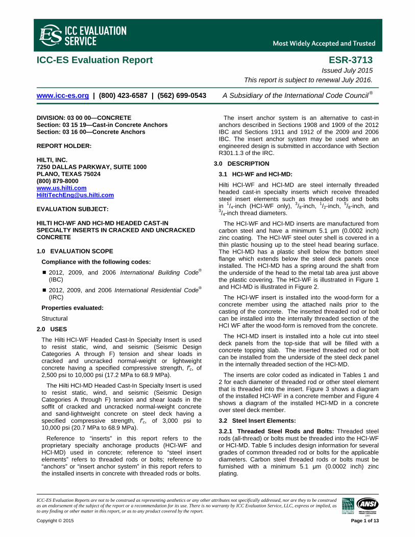
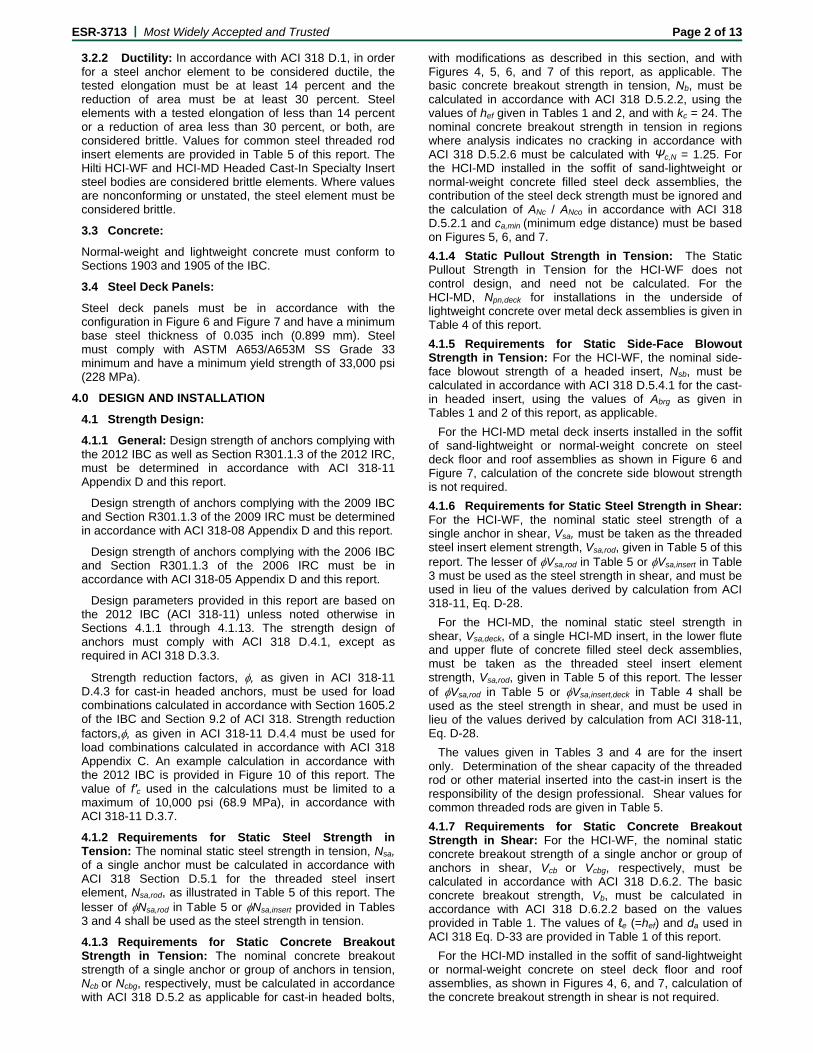
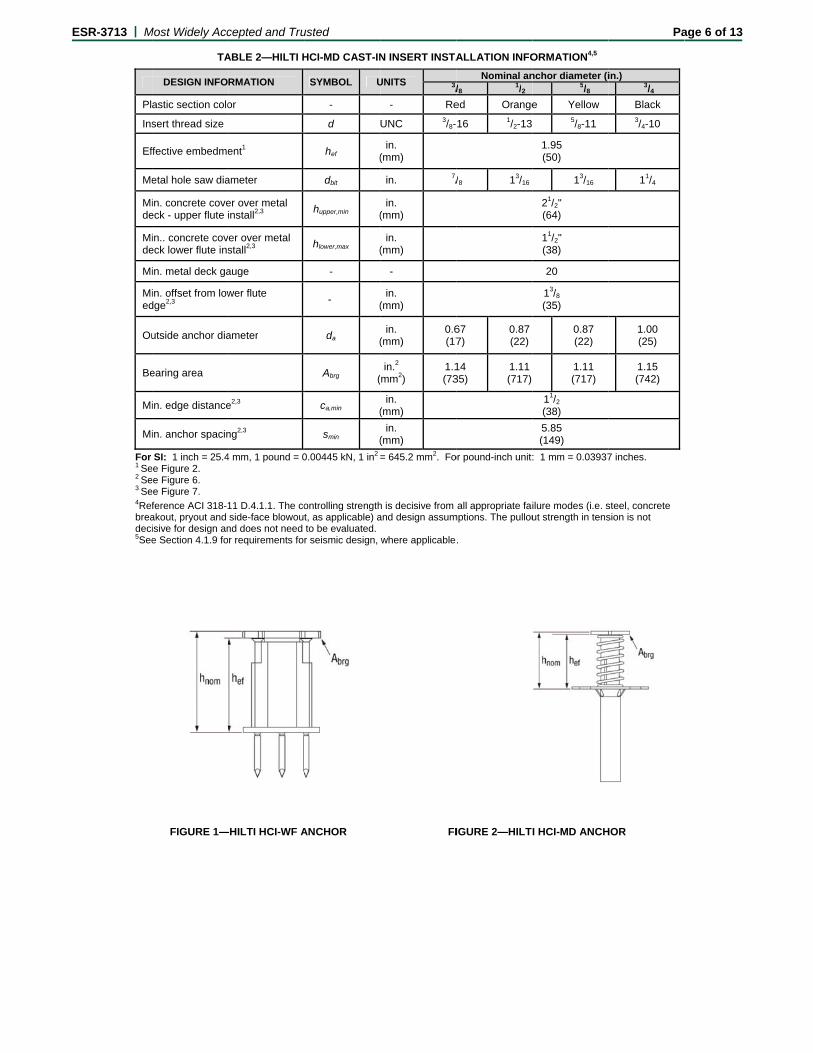
The HCI-WF and HCI-MD inserts are manufactured from carbon steel and have a minimum 5.1 μm (0.0002 inch) zinc coating. The HCI-WF steel outer shell is covered in a thin plastic housing up to the steel head bearing surface. The HCI-MD has a plastic shell below the bottom steel flange which extends below the steel deck panels once installed. The HCI-MD has a spring around the shaft from the underside of the head to the metal tab area just above the plastic covering. The HCI-WF is illustrated in Figure 1 and HCI-MD is illustrated in Figure 2.
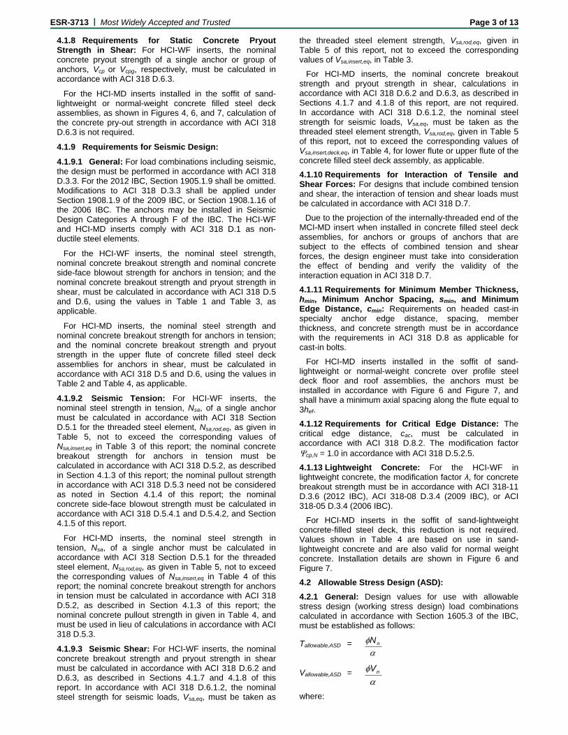
The HCI-WF insert is installed into the wood-form for a concrete member using the attached nails prior to the casting of the concrete. The inserted threaded rod or bolt can be installed into the internally threaded section of the HCI WF after the wood-form is removed from the concrete.
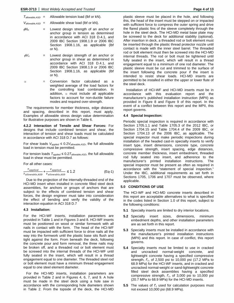
The HCI-MD insert is installed into a hole cut into steel deck panels from the top-side that will be filled with a concrete topping slab. The inserted threaded rod or bolt can be installed from the underside of the steel deck panel in the internally threaded section of the HCI-MD.
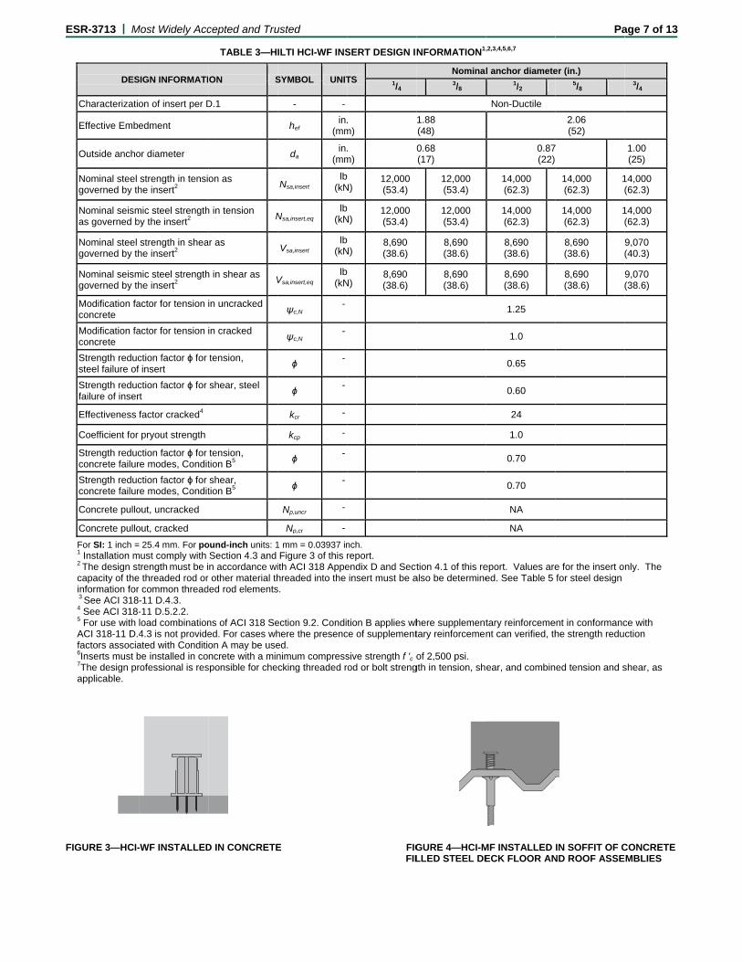
The inserts are color coded as indicated in Tables 1 and 2 for each diameter of threaded rod or other steel element that is threaded into the insert. Figure 3 shows a diagram of the installed HCI-WF in a concrete member and Figure 4 shows a diagram of the installed HCI-MD in a concrete over steel deck member.
3.2 Steel Insert Elements:
3.2.1 Threaded Steel Rods and Bolts: Threaded steel rods (all-thread) or bolts must be threaded into the HCI-WF or HCI-MD. Table 5 includes design information for several grades of common threaded rod or bolts for the applicable diameters. Carbon steel threaded rods or bolts must be furnished with a minimum 5.1 μm (0.0002 inch) zinc plating.
ESR-3713 | Most Widely Accepted and Trusted Page 2 of 13
3.2.2 Ductility: In accordance with ACI 318 D.1, in order for a steel anchor element to be considered ductile, the tested elongation must be at least 14 percent and the reduction of area must be at least 30 percent. Steel elements with a tested elongation of less than 14 percent or a reduction of area less than 30 percent, or both, are considered brittle. Values for common steel threaded rod insert elements are provided in Table 5 of this report. The Hilti HCI-WF and HCI-MD Headed Cast-In Specialty Insert steel bodies are considered brittle elements. Where values are nonconforming or unstated, the steel element must be considered brittle. 3.3 Concrete:
Normal-weight and lightweight concrete must conform to Sections 1903 and 1905 of the IBC.
3.4 Steel Deck Panels:
Steel deck panels must be in accordance with the configuration in Figure 6 and Figure 7 and have a minimum base steel thickness of 0.035 inch (0.899 mm). Steel must comply with ASTM A653/A653M SS Grade 33 minimum and have a minimum yield strength of 33,000 psi (228 MPa).
4.0 DESIGN AND INSTALLATION
4.1 Strength Design:
4.1.1 General: Design strength of anchors complying with the 2012 IBC as well as Section R301.1.3 of the 2012 IRC, must be determined in accordance with ACI 318-11 Appendix D and this report.
Design strength of anchors complying with the 2009 IBC and Section R301.1.3 of the 2009 IRC must be determined in accordance with ACI 318-08 Appendix D and this report.
Design strength of anchors complying with the 2006 IBC and Section R301.1.3 of the 2006 IRC must be in accordance with ACI 318-05 Appendix D and this report.
Design parameters provided in this report are based on the 2012 IBC (ACI 318-11) unless noted otherwise in Sections 4.1.1 through 4.1.13. The strength design of anchors must comply with ACI 318 D.4.1, except as required in ACI 318 D.3.3.
Strength reduction factors, , as given in ACI 318-11 D.4.3 for cast-in headed anchors, must be used for load combinations calculated in accordance with Section 1605.2 of the IBC and Section 9.2 of ACI 318. Strength reduction factors,, as given in ACI 318-11 D.4.4 must be used for load combinations calculated in accordance with ACI 318 Appendix C. An example calculation in accordance with the 2012 IBC is provided in Figure 10 of this report. The value of f′c used in the calculations must be limited to a maximum of 10,000 psi (68.9 MPa), in accordance with ACI 318-11 D.3.7.
4.1.2 Requirements for Static Steel Strength in Tension: The nominal static steel strength in tension, Nsa, of a single anchor must be calculated in accordance with ACI 318 Section D.5.1 for the threaded steel insert element, Nsa,rod, as illustrated in Table 5 of this report. The lesser of Nsa,rod in Table 5 or Nsa,insert provided in Tables 3 and 4 shall be used as the steel strength in tension.
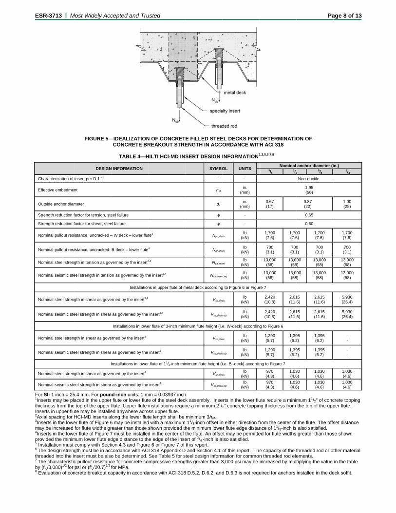
4.1.3 Requirements for Static Concrete Breakout Strength in Tension: The nominal concrete breakout strength of a single anchor or group of anchors in tension, Ncb or Ncbg, respectively, must be calculated in accordance with ACI 318 D.5.2 as applicable for cast-in headed bolts,
with modifications as described in this section, and with Figures 4, 5, 6, and 7 of this report, as applicable. The basic concrete breakout strength in tension, Nb, must be calculated in accordance with ACI 318 D.5.2.2, using the values of hef given in Tables 1 and 2, and with kc = 24. The nominal concrete breakout strength in tension in regions where analysis indicates no cracking in accordance with ACI 318 D.5.2.6 must be calculated with Ψc,N = 1.25. For the HCI-MD installed in the soffit of sand-lightweight or normal-weight concrete filled steel deck assemblies, the contribution of the steel deck strength must be ignored and the calculation of ANc / ANco in accordance with ACI 318 D.5.2.1 and ca,min (minimum edge distance) must be based on Figures 5, 6, and 7. 4.1.4 Static Pullout Strength in Tension: The Static Pullout Strength in Tension for the HCI-WF does not control design, and need not be calculated. For the HCI-MD, Npn,deck for installations in the underside of lightweight concrete over metal deck assemblies is given in Table 4 of this report.
4.1.5 Requirements for Static Side-Face Blowout Strength in Tension: For the HCI-WF, the nominal side-face blowout strength of a headed insert, Nsb, must be calculated in accordance with ACI 318 D.5.4.1 for the cast-in headed insert, using the values of Abrg as given in Tables 1 and 2 of this report, as applicable.
For the HCI-MD metal deck inserts installed in the soffit of sand-lightweight or normal-weight concrete on steel deck floor and roof assemblies as shown in Figure 6 and Figure 7, calculation of the concrete side blowout strength is not required.
4.1.6 Requirements for Static Steel Strength in Shear: For the HCI-WF, the nominal static steel strength of a single anchor in shear, Vsa, must be taken as the threaded steel insert element strength, Vsa,rod, given in Table 5 of this report. The lesser of Vsa,rod in Table 5 or Vsa,insert in Table 3 must be used as the steel strength in shear, and must be used in lieu of the values derived by calculation from ACI 318-11, Eq. D-28.
For the HCI-MD, the nominal static steel strength in shear, Vsa,deck, of a single HCI-MD insert, in the lower flute and upper flute of concrete filled steel deck assemblies, must be taken as the threaded steel insert element strength, Vsa,rod, given in Table 5 of this report. The lesser of Vsa,rod in Table 5 or Vsa,insert,deck in Table 4 shall be used as the steel strength in shear, and must be used in lieu of the values derived by calculation from ACI 318-11, Eq. D-28.
The values given in Tables 3 and 4 are for the insert only. Determination of the shear capacity of the threaded rod or other material inserted into the cast-in insert is the responsibility of the design professional. Shear values for common threaded rods are given in Table 5.
4.1.7 Requirements for Static Concrete Breakout Strength in Shear: For the HCI-WF, the nominal static concrete breakout strength of a single anchor or group of anchors in shear, Vcb or Vcbg, respectively, must be calculated in accordance with ACI 318 D.6.2. The basic concrete breakout strength, Vb, must be calculated in accordance with ACI 318 D.6.2.2 based on the values provided in Table 1. The values of ℓe (=hef) and da used in ACI 318 Eq. D-33 are provided in Table 1 of this report.
For the HCI-MD installed in the soffit of sand-lightweight or normal-weight concrete on steel deck floor and roof assemblies, as shown in Figures 4, 6, and 7, calculation of the concrete breakout strength in shear is not required.
ESR-3713 | Most Widely Accepted and Trusted Page 3 of 13
4.1.8 Requirements for Static Concrete Pryout Strength in Shear: For HCI-WF inserts, the nominal concrete pryout strength of a single anchor or group of anchors, Vcp or Vcpg, respectively, must be calculated in accordance with ACI 318 D.6.3.
For the HCI-MD inserts installed in the soffit of sand-lightweight or normal-weight concrete filled steel deck assemblies, as shown in Figures 4, 6, and 7, calculation of the concrete pry-out strength in accordance with ACI 318 D.6.3 is not required.
4.1.9 Requirements for Seismic Design:
4.1.9.1 General: For load combinations including seismic, the design must be performed in accordance with ACI 318 D.3.3. For the 2012 IBC, Section 1905.1.9 shall be omitted. Modifications to ACI 318 D.3.3 shall be applied under Section 1908.1.9 of the 2009 IBC, or Section 1908.1.16 of the 2006 IBC. The anchors may be installed in Seismic Design Categories A through F of the IBC. The HCI-WF and HCI-MD inserts comply with ACI 318 D.1 as non-ductile steel elements.
For the HCI-WF inserts, the nominal steel strength, nominal concrete breakout strength and nominal concrete side-face blowout strength for anchors in tension; and the nominal concrete breakout strength and pryout strength in shear, must be calculated in accordance with ACI 318 D.5 and D.6, using the values in Table 1 and Table 3, as applicable.
For HCI-MD inserts, the nominal steel strength and nominal concrete breakout strength for anchors in tension; and the nominal concrete breakout strength and pryout strength in the upper flute of concrete filled steel deck assemblies for anchors in shear, must be calculated in accordance with ACI 318 D.5 and D.6, using the values in Table 2 and Table 4, as applicable.
4.1.9.2 Seismic Tension: For HCI-WF inserts, the nominal steel strength in tension, Nsa, of a single anchor must be calculated in accordance with ACI 318 Section D.5.1 for the threaded steel element, Nsa,rod,eq, as given in Table 5, not to exceed the corresponding values of Nsa,insert,eq in Table 3 of this report; the nominal concrete breakout strength for anchors in tension must be calculated in accordance with ACI 318 D.5.2, as described in Section 4.1.3 of this report; the nominal pullout strength in accordance with ACI 318 D.5.3 need not be considered as noted in Section 4.1.4 of this report; the nominal concrete side-face blowout strength must be calculated in accordance with ACI 318 D.5.4.1 and D.5.4.2, and Section 4.1.5 of this report.
For HCI-MD inserts, the nominal steel strength in tension, Nsa, of a single anchor must be calculated in accordance with ACI 318 Section D.5.1 for the threaded steel element, Nsa,rod,eq, as given in Table 5, not to exceed the corresponding values of Nsa,insert,eq in Table 4 of this report; the nominal concrete breakout strength for anchors in tension must be calculated in accordance with ACI 318 D.5.2, as described in Section 4.1.3 of this report; the nominal concrete pullout strength in given in Table 4, and must be used in lieu of calculations in accordance with ACI 318 D.5.3.
4.1.9.3 Seismic Shear: For HCI-WF inserts, the nominal concrete breakout strength and pryout strength in shear must be calculated in accordance with ACI 318 D.6.2 and D.6.3, as described in Sections 4.1.7 and 4.1.8 of this report. In accordance with ACI 318 D.6.1.2, the nominal steel strength for seismic loads, Vsa,eq, must be taken as
the threaded steel element strength, Vsa,rod,eq, given in Table 5 of this report, not to exceed the corresponding values of Vsa,insert,eq, in Table 3.
For HCI-MD inserts, the nominal concrete breakout strength and pryout strength in shear, calculations in accordance with ACI 318 D.6.2 and D.6.3, as described in Sections 4.1.7 and 4.1.8 of this report, are not required. In accordance with ACI 318 D.6.1.2, the nominal steel strength for seismic loads, Vsa,eq, must be taken as the threaded steel element strength, Vsa,rod,eq, given in Table 5 of this report, not to exceed the corresponding values of Vsa,insert,deck,eq, in Table 4, for lower flute or upper flute of the concrete filled steel deck assembly, as applicable.
4.1.10 Requirements for Interaction of Tensile and Shear Forces: For designs that include combined tension and shear, the interaction of tension and shear loads must be calculated in accordance with ACI 318 D.7.
Due to the projection of the internally-threaded end of the MCI-MD insert when installed in concrete filled steel deck assemblies, for anchors or groups of anchors that are subject to the effects of combined tension and shear forces, the design engineer must take into consideration the effect of bending and verify the validity of the interaction equation in ACI 318 D.7.
4.1.11 Requirements for Minimum Member Thickness, hmin, Minimum Anchor Spacing, smin, and Minimum Edge Distance, cmin: Requirements on headed cast-in specialty anchor edge distance, spacing, member thickness, and concrete strength must be in accordance with the requirements in ACI 318 D.8 as applicable for cast-in bolts.
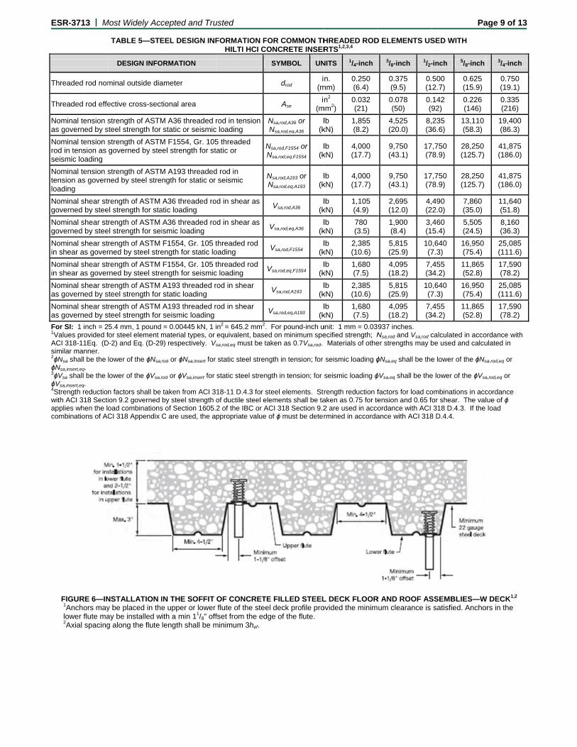
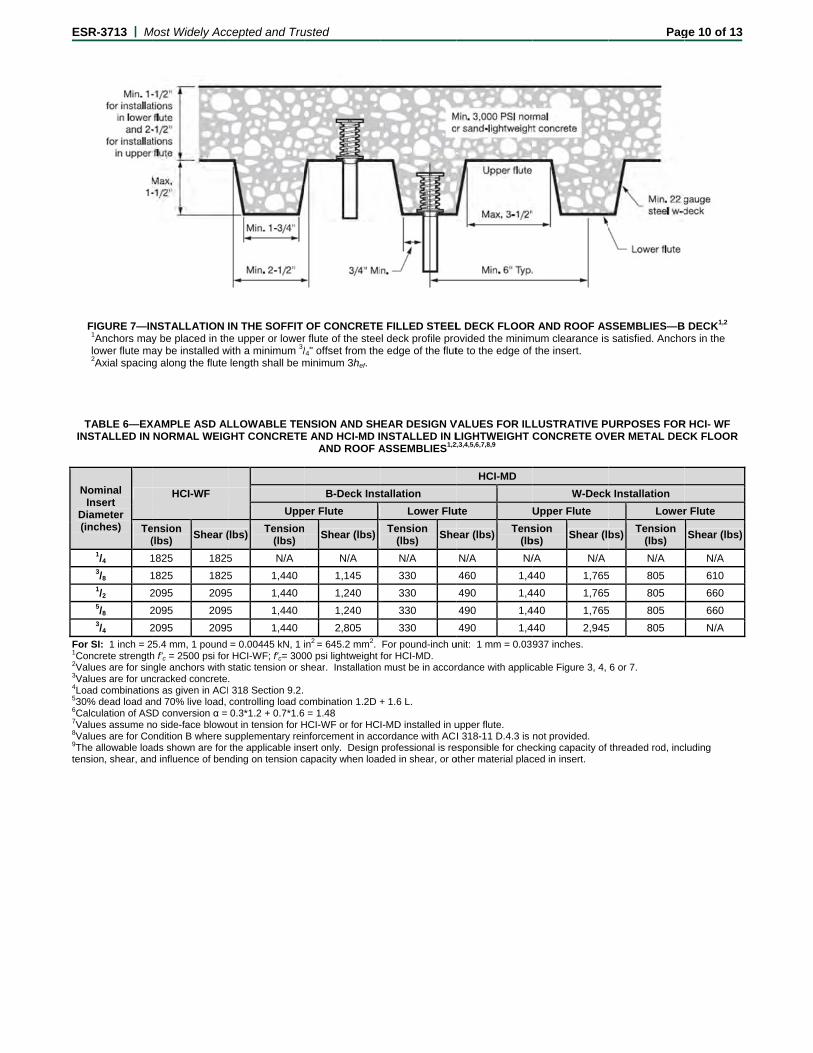
For HCI-MD inserts installed in the soffit of sand-lightweight or normal-weight concrete over profile steel deck floor and roof assemblies, the anchors must be installed in accordance with Figure 6 and Figure 7, and shall have a minimum axial spacing along the flute equal to 3hef.
4.1.12 Requirements for Critical Edge Distance: The critical edge distance, cac, must be calculated in accordance with ACI 318 D.8.2. The modification factor cp,N = 1.0 in accordance with ACI 318 D.5.2.5. 4.1.13 Lightweight Concrete: For the HCI-WF in lightweight concrete, the modification factor λ, for concrete breakout strength must be in accordance with ACI 318-11 D.3.6 (2012 IBC), ACI 318-08 D.3.4 (2009 IBC), or ACI 318-05 D.3.4 (2006 IBC).
For HCI-MD inserts in the soffit of sand-lightweight concrete-filled steel deck, this reduction is not required. Values shown in Table 4 are based on use in sand-lightweight concrete and are also valid for normal weight concrete. Installation details are shown in Figure 6 and Figure 7.
4.2 Allowable Stress Design (ASD):
4.2.1 General: Design values for use with allowable stress design (working stress design) load combinations calculated in accordance with Section 1605.3 of the IBC, must be established as follows:
Tallowable,ASD = nN
Vallowable,ASD = nV
where:
ESR-3713 | Most Widely Accepted and Trusted Page 4 of 13
Tallowable,ASD = Allowable tension load (lbf or kN).
Vallowable,ASD = Allowable shear load (lbf or kN).
Nn = Lowest design strength of an anchor or anchor group in tension as determined in accordance with ACI 318 D.4.1, and 2009 IBC Section 1908.1.9 or 2006 IBC Section 1908.1.16, as applicable (lbf or N).
Vn = Lowest design strength of an anchor or anchor group in shear as determined in accordance with ACI 318 D.4.1, and 2009 IBC Section 1908.1.9 or 2006 IBC Section 1908.1.16, as applicable (lbf or N).
α = Conversion factor calculated as a weighted average of the load factors for the controlling load combination. In addition, α must include all applicable factors to account for non-ductile failure modes and required over-strength.
The requirements for member thickness, edge distance and spacing, described in this report, must apply. Examples of allowable stress design value determination for illustrative purposes are shown in Table 6.
4.2.2 Interaction of Tensile and Shear Forces: For designs that include combined tension and shear, the interaction of tension and shear loads must be calculated in accordance with ACI 318 D.7 as follows:
For shear loads Vapplied ≤ 0.2Vallowable,ASD, the full allowable load in tension must be permitted.
For tension loads Tapplied ≤ 0.2Tallowable,ASD, the full allowable load in shear must be permitted.
For all other cases:
,+
,≤1.2 (Eq-1)
Due to the projection of the internally-threaded end of the HCI-MD insert when installed in concrete filled steel deck assemblies, for anchors or groups of anchors that are subject to the effects of combined tension and shear forces, the design engineer must take into consideration the effect of bending and verify the validity of the interaction equation in ACI 318 D.7
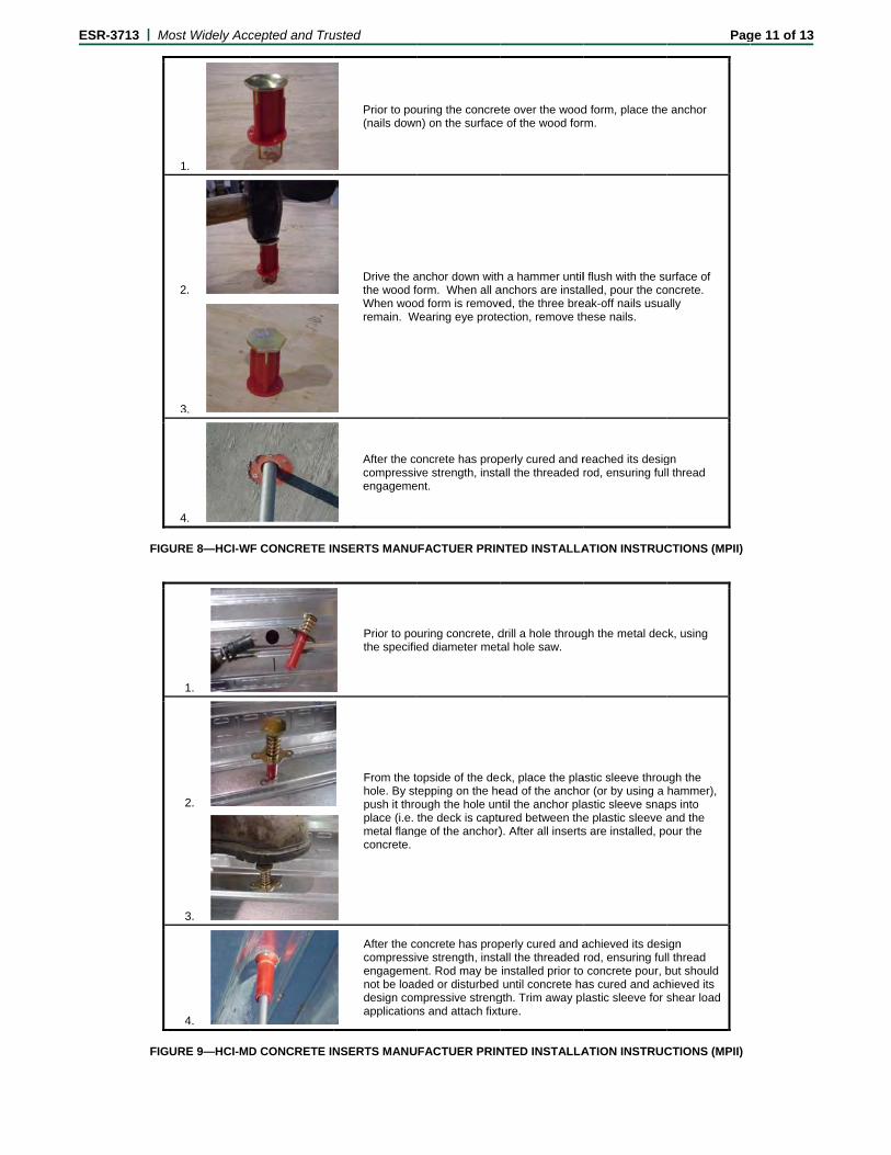
4.3 Installation:
For the HCI-WF inserts, installation parameters are provided in Table 1 and in Figures 3 and 8. HCI-WF inserts must be positioned on wood or similar formwork with all nails in contact with the form. The head of the HCI-WF must be impacted with sufficient force to drive nails all the way into the formwork until the plastic base sits flush and tight against the form. From beneath the deck, following the concrete pour and form removal, the three nails may be broken off, and a threaded rod or bolt element must be screwed into the internal threads of the HCI-WF until fully seated in the insert, which will result in a thread engagement equal to one diameter. The threaded steel rod or bolt element must have a minimum thread engagement equal to one steel element diameter.
For the HCI-MD inserts, installation parameters are provided in Table 2 and in Figures 4, 6, 7, and 9. A hole must be made in the steel deck using a hole saw in accordance with the corresponding hole diameters shown in Table 2. From the topside of the deck, the HCI-MD
plastic sleeve must be placed in the hole, and following this, the head of the insert must be stepped on or impacted with sufficient force to compress the outer spring and drive the flared plastic fins of the sleeve completely through the hole in the steel deck. The HCI-MD metal base plate may be screwed to the deck for additional stability (optional). After insertion in deck, a threaded rod or bolt element must be inserted through the plastic thread protector nozzle until contact is made with the inner steel barrel. The threaded rod or bolt element must then be screwed into the HCI-MD internal threads. The rod or bolt must be tightened until fully seated in the insert, which will result in a thread engagement equal to a minimum of one rod diameter. The plastic sleeve must be cut and trimmed to the surface of the insert following the concrete pour if the insert is intended to resist shear loads. HCI-MD inserts are permitted to be installed in either the upper or lower flute of the steel deck.
Installation of HCI-WF and HCI-MD inserts must be in accordance with this evaluation report and the manufacturer’s published installation instruction (MPII) as provided in Figure 8 and Figure 9 of this report. In the event of a conflict between this report and the MPII, this report governs.
4.4 Special Inspection:
Periodic special inspection is required in accordance with Section 1705.1.1 and Table 1705.3 of the 2012 IBC, or Section 1704.15 and Table 1704.4 of the 2009 IBC, or Section 1704.13 of the 2006 IBC, as applicable. The special inspector must make periodic inspections during installation of the headed cast-in specialty inserts to verify insert type, insert dimensions, concrete type, concrete compressive strength, insert spacing, edge distances, concrete member thickness, insert embedment, threaded rod fully seated into insert, and adherence to the manufacturer’s printed installation instructions. The special inspector must be present as often as required in accordance with the “statement of special inspection.” Under the IBC, additional requirements as set forth in Sections 1705, 1706 and 1707 must be observed, where applicable.
5.0 CONDITIONS OF USE
The HCI-WF and HCI-MD concrete inserts described in this report are acceptable alternatives to what is specified in the codes listed in Section 1.0 of this report, subject to the following conditions:
5.1 Specialty inserts are limited to dry interior locations.
5.2 Specialty insert sizes, dimensions, minimum embedment depths, and other installation parameters are as set forth in this report.
5.3 Specialty inserts must be installed in accordance with the manufacturer’s printed installation instructions (MPII) and this report. In case of conflict, this report governs.
5.4 Specialty inserts must be limited to use in cracked and uncracked normal-weight concrete, and lightweight concrete having a specified compressive strength, f'c, of 2,500 psi to 10,000 psi (17.2 MPa to 68.9 MPa) for the HCI-WF inserts, and in cracked and uncracked normal-weight or sand-lightweight concrete filled steel deck assemblies having a specified compressive strength, f'c, of 3,000 psi to 10,000 psi (20.7 MPa to 68.9 MPa) for the HCI-MD inserts.
5.5 The values of f'c used for calculation purposes must not exceed 10,000 psi (68.9 MPa).
ESR-3713 | Most Widely Accepted and Trusted Page 5 of 13
5.6 Strength design values must be established in accordance with Section 4.1 of this report.
5.7 Allowable design values are established in accordance with Section 4.2.
5.8 Specialty insert spacing and edge distance as well as minimum member thickness must comply with ACI 318 Section D.8 requirements for cast-in-place headed anchors, and Table 1 and Table 2, and Figure 6 and Figure 7 of this report.
5.9 Prior to installation, calculations and details demonstrating compliance with this report must be submitted to the code official. The calculations and details must be prepared by a registered design professional where required by the statutes of the jurisdiction in which the project is to be constructed.
5.10 Since an ICC-ES acceptance criteria for evaluating data to determine the performance of the specialty inserts subjected to fatigue or shock loading is unavailable at this time, the use of these inserts under such conditions is beyond the scope of this report.
5.11 Specialty inserts may be installed in regions of concrete where analysis indicates cracking may occur (ft > fr), subject to the conditions of this report.
5.12 Specialty inserts may be used to resist short-term loading due to wind or seismic forces in locations designated as Seismic Design Categories A through F of the IBC, subject to the conditions of this report.
5.13 Where not otherwise prohibited in the code, inserts are permitted for use with fire-resistance-rated construction provided that at least one of the following conditions is fulfilled:
Headed cast-in specialty inserts that support a fire-resistance-rated envelope or a fire- resistance-rated membrane are protected by approved fire-resistance-rated materials, or have been evaluated for resistance to fire exposure in accordance with recognized standards.
Headed cast-in specialty inserts are used to resist wind or seismic forces only.
Headed cast-in specialty inserts are used to support nonstructural elements.
5.14 Special inspection must be provided in accordance with Section 4.4.
5.15 Specialty inserts are manufactured under an approved quality control program with inspections by ICC-ES.
6.0 EVIDENCE SUBMITTED
6.1 Data in accordance with the ICC-ES Acceptance Criteria for Headed Cast-in Specialty Inserts in Concrete (AC446), dated February 2015.
6.2 Quality-control documentation.
7.0 IDENTIFICATION
The HCI-WF and HCI-MD inserts are identified by packaging labeled with the manufacturer’s name (Hilti, Inc.) and contact information, insert name, insert size, lot number and evaluation report number (ESR-3713). The inserts have various colored plastic housings to identify the product size.
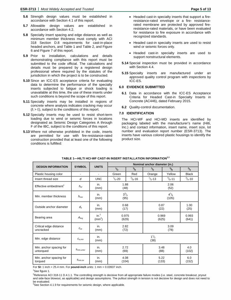
TABLE 1—HILTI HCI-WF CAST-IN INSERT INSTALLATION INFORMATION2,3
DESIGN INFORMATION SYMBOL UNITS Nominal anchor diameter (in.)
1/4 3/8
1/2 5/8
3/4
Plastic housing color - - Green Red Orange Yellow Black
Insert thread size d UNC 1/4-20 3/8-16 1/2-13 5/8-11 3/4-10
Effective embedment1 hef in.
(mm) 1.88 (48)
2.06 (52)
Min. member thickness hmin in.
(mm) 33/4 (95)
41/8 (105)
Outside anchor diameter da in.
(mm) 0.68 (17)
0.87 (22)
1.00 (25)
Bearing area Abrg in.2
(mm2) 0.975 (629)
0.969 (625)
0.993 (641)
Critical edge distance uncracked
cac in.
(mm) 2.82 (72)
3.09 (78)
Min. edge distance ca,min in.
(mm) 11/2 (38)
Min. anchor spacing for untorqued
smin,untor in.
(mm) 2.72 (69)
3.48 (88)
4.0 (102)
Min. anchor spacing for torqued
smin.tor in.
(mm) 4.08 (104)
5.22 (133)
6.0 (152)
For SI: 1 inch = 25.4 mm. For pound-inch units: 1 mm = 0.03937 inch. 1See figure 1. 2Reference ACI 318-11 D.4.1.1. The controlling strength is decisive from all appropriate failure modes (i.e. steel, concrete breakout, pryout and side-face blowout, as applicable) and design assumptions. The pullout strength in tension is not decisive for design and does not need to be evaluated. 3See Section 4.1.9 for requirements for seismic design, where applicable.
E
ESR-3713 | M
Pl
Ins
Ef
Me
Mide
Mide
Mi
Mied
Ou
Be
Mi
Mi
For 1 Se2 Se3 Se4Refbreadeci5See
Most Widely Acc
TA
DESIGN INFO
astic section colo
sert thread size
ffective embedme
etal hole saw dia
in. concrete coveeck - upper flute i
in.. concrete coveck lower flute ins
in. metal deck ga
in. offset from lowdge2,3
utside anchor dia
earing area
in. edge distance
in. anchor spacin
SI: 1 inch = 25.4ee Figure 2. ee Figure 6. ee Figure 7.
ference ACI 318-1akout, pryout and isive for design ane Section 4.1.9 fo
FIGURE 1—
cepted and Tru
ABLE 2—HILTI H
RMATION
or
ent1
ameter
er over metal install2,3
ver over metal stall2,3
auge
wer flute
ameter
e2,3
ng2,3
4 mm, 1 pound = 0
11 D.4.1.1. The coside-face blowou
nd does not need r requirements fo
—HILTI HCI-WF A
usted
HCI-MD CAST-IN
SYMBOL U
-
d
hef (
dbit
hupper,min (
hlower,max (
-
- (
da (
Abrg (
ca,min (
smin (
0.00445 kN, 1 in2
ontrolling strengtht, as applicable) ato be evaluated.r seismic design,
ANCHOR
N INSERT INSTA
UNITS 3/
- Re
UNC 3/8-
in. (mm)
in. 7/
in. (mm)
in. (mm)
-
in. (mm)
in. (mm)
0.6(17
in.2 mm2)
1.1(73
in. (mm)
in. (mm)
= 645.2 mm2. Fo
h is decisive from and design assum
where applicable
FI
ALLATION INFO
Nominal an/8
1/2
ed Orange
-16 1/2-13
/8 13/16
67 7)
0.87(22)
14 35)
1.11(717)
or pound-inch unit:
all appropriate faimptions. The pullou
.
IGURE 2—HILT
ORMATION4,5
nchor diameter (i 5/8
e Yellow
5/8-11
1.95 (50)
13/16
21/2" (64)
11/2" (38)
20
13/8 (35)
0.87 (22)
1.11 (717)
11/2 (38)
5.85 (149)
: 1 mm = 0.03937
ilure modes (i.e. sut strength in tens
I HCI-MD ANCH
Pa
in.) 3/4
Black 3/4-10
11/4
1.00 (25)
1.15 (742)
7 inches.
steel, concrete sion is not
HOR
age 6 of 13
E
F
ESR-3713 | M
DES
Characterizatio
Effective Embe
Outside ancho
Nominal steel governed by th
Nominal seismas governed b
Nominal steel governed by th
Nominal seismgoverned by th
Modification faconcrete
Modification faconcrete
Strength reducsteel failure of
Strength reducfailure of inser
Effectiveness
Coefficient for
Strength reducconcrete failur
Strength reducconcrete failur
Concrete pullo
Concrete pullo
For SI: 1 inch =1 Installation m2 The design stcapacity of theinformation for 3 See ACI 3184 See ACI 318-5 For use with ACI 318-11 D.4factors associa6Inserts must b7The design prapplicable.
FIGURE 3—HCI-
Most Widely Acc
SIGN INFORMATI
on of insert per D
edment
or diameter
strength in tensihe insert2
mic steel strengthby the insert2
strength in sheahe insert2
mic steel strengthhe insert2
actor for tension
actor for tension
ction factor ϕ for f insert
ction factor ϕ for rt
factor cracked4
pryout strength
ction factor ϕ for re modes, Condit
ction factor ϕ for re modes, Condit
out, uncracked
out, cracked
= 25.4 mm. For pomust comply with
trength must be ie threaded rod orr common thread-11 D.4.3. -11 D.5.2.2. load combination4.3 is not provideated with Conditibe installed in corofessional is res
-WF INSTALLED
cepted and Tru
TABLE 3—H
ON S
D.1
on as
h in tension N
ar as
h in shear as V
in uncracked
in cracked
tension,
shear, steel
tension, tion B5
shear, tion B5
ound-inch units: 1Section 4.3 and n accordance wi
r other material thded rod elements
ns of ACI 318 Seed. For cases whon A may be usencrete with a min
sponsible for che
D IN CONCRETE
usted
ILTI HCI-WF INS
SYMBOL UNIT
- -
hef in.
(mm
da in.
(mm
Nsa,insert lb
(kN
Nsa,insert,eq lb
(kN
Vsa,insert lb
(kN
Vsa,insert,eq lb
(kN
ψc,N -
ψc,N -
ϕ -
ϕ -
kcr -
kcp -
ϕ -
ϕ -
Np,uncr -
Np,cr -
1 mm = 0.03937 inFigure 3 of this r
ith ACI 318 Appehreaded into the s.
ection 9.2. Condihere the presenced. nimum compresscking threaded r
E
SERT DESIGN IN
TS 1/4
. m)
. m)
N)
12,000 (53.4)
N)
12,000 (53.4)
N)
8,690 (38.6)
N)
8,690 (38.6)
nch. report. endix D and Sectinsert must be a
tion B applies whce of supplement
sive strength f 'c orod or bolt streng
FIGFIL
NFORMATION1,
Nominal3/8
1.88 (48)
0.68 (17)
12,000 (53.4)
12,000 (53.4)
8,690 (38.6)
8,690 (38.6)
tion 4.1 of this realso be determine
here supplementtary reinforcemen
of 2,500 psi. gth in tension, sh
GURE 4—HCI-MLLED STEEL DE
,2,3,4,5,6,7
l anchor diamete1/2
Non-Ductile
0.87(22)
14,000 (62.3)
14,000 (62.3)
8,690 (38.6)
8,690 (38.6)
1.25
1.0
0.65
0.60
24
1.0
0.70
0.70
NA
NA
eport. Values areed. See Table 5
tary reinforcement can verified, th
ear, and combin
MF INSTALLED ECK FLOOR AN
Pa
er (in.) 5/8
2.06 (52)
7
14,000 (62.3)
1(
14,000 (62.3)
1(
8,690 (38.6) (
8,690 (38.6) (
e for the insert ofor steel design
ent in conformanche strength redu
ed tension and s
IN SOFFIT OF CND ROOF ASSE
age 7 of 13
3/4
1.00 (25)
14,000 (62.3)
14,000 (62.3)
9,070 (40.3)
9,070 (38.6)
nly. The
ce with ction
shear, as
CONCRETE MBLIES
E
F1
thIn2A3
m4
p5 6
th7
b8
ESR-3713 | M
Characterization of
Effective embedme
Outside anchor diam
Strength reduction f
Strength reduction f
Nominal pullout res
Nominal pullout res
Nominal steel stren
Nominal seismic ste
Nominal steel stren
Nominal seismic ste
Nominal steel stren
Nominal seismic ste
Nominal steel stren
Nominal seismic ste
For SI: 1 inch = 25Inserts may be plahickness from thenserts in upper fluAxial spacing for Inserts in the lowe
may be increased Inserts in the lowe
provided the minimInstallation must The design strenhreaded into the iThe characteristic
by (f'c/3,000)1/2 for Evaluation of con
Most Widely Acc
FIGURE 5—
DESIGN
insert per D.1.1
nt
meter
factor for tension, ste
factor for shear, stee
istance, uncracked –
istance, uncracked-
gth in tension as gov
eel strength in tensio
gth in shear as gove
eel strength in shear
gth in shear as gove
eel strength in shear
gth in shear as gove
eel strength in shear
5.4 mm. For pounaced in the upper
e top of the upper ute may be installeHCI-MD inserts aer flute of Figure 6for flute widths gr
er flute of Figure 7mum lower flute edcomply with Sectgth must be in accnsert must be alsoc pullout resistancpsi or (f'c/20.7)1/2
ncrete breakout ca
cepted and Tru
—IDEALIZATIONCONCRETE BR
TABLE 4—H
N INFORMATION
eel failure
el failure
– W deck – lower flut
B deck – lower flute
verned by the insert3
on as governed by th
Installation
erned by the insert3,4
r as governed by the
Installations in lowe
erned by the insert3
r as governed by the
Installations in lower
erned by the insert4
r as governed by the
nd-inch units: 1 mr flute or lower flutflute. Upper flute ed anywhere acrolong the lower flut6 may be installedreater than those 7 must be installeddge distance to thion 4.3 and Figurecordance with ACo be determined. ce for concrete cofor MPa. apacity in accorda
usted
N OF CONCRETREAKOUT STRE
HILTI HCI-MD IN
te3
4
3,4
he insert3,4
ns in upper flute of m
insert3,4
er flute of 3-inch min
insert3
r flute of 11/2-inch min
insert4
mm = 0.03937 inchte of the steel decinstallations requi
oss upper flute. te length shall be
d with a maximumshown provided thd in the center of
he edge of the insee 6 or Figure 7 of
CI 318 Appendix DSee Table 5 for s
ompressive streng
ance with ACI 318
TE FILLED STEEENGTH IN ACCO
SERT DESIGN I
SYMBO
-
hef
da
ϕ
ϕ
Npn,dec
Npn,dec
Nsa,inse
Nsa,inser
metal deck according
Vsa,dec
Vsa,deck
imum flute height (i.e
Vsa,dec
Vsa,deck
nimum flute height (i
Vsa,dec
Vsa,deck
h. k assembly. Inseire a minimum 21/
minimum 3hef. 11/8-inch offset inhe minimum lowethe flute. An offseert of 3/4 -inch is athis report.
D and Section 4.1 steel design informths greater than 3
8 D.5.2, D.6.2, and
EL DECKS FOR ORDANCE WIT
INFORMATION1
OL UNITS
-
in. (mm)
in. (mm)
-
-
ck lb
(kN)
ck lb
(kN)
ert lb
(kN)
rt,eq lb
(kN)
g to Figure 6 or Figur
ck lb
(kN)
k,eq lb
(kN)
e. W-deck) accordin
ck lb
(kN)
k,eq lb
(kN)
i.e. B -deck) accordi
ck lb
(kN)
k,eq lb
(kN)
erts in the lower flu/2" concrete toppin
n either direction fer flute edge distanet may be permittelso satisfied.
of this report. Thmation for commo3,000 psi may be
d D.6.3 is not requ
DETERMINATIOTH ACI 318
1,2,5,6,7,8
Nominal
3/8 1/2
0.67 (17)
1,700 (7.6)
1,70(7.6
700 (3.1)
700(3.1
13,000 (58)
13,0(58
13,000 (58)
13,0(58
re 7
2,420 (10.8)
2,61(11.
2,420 (10.8)
2,61(11.
ng to Figure 6
1,290 (5.7)
1,39(6.2
1,290 (5.7)
1,39(6.2
ng to Figure 7
970 (4.3)
1,03(4.6
970 (4.3)
1,03(4.6
ute require a mining thickness from
from the center of nce of 11/8-inch ised for flute widths
e capacity of the tn threaded rod eleincreased by mul
uired for anchors
Pa
ON OF
anchor diameter (i
2 5/8
Non-ductile
1.95 (50)
0.87 (22)
0.65
0.60
00 6)
1,700 (7.6)
0 1)
700 (3.1)
00 8)
13,000 (58)
00 8)
13,000 (58)
15 6)
2,615 (11.6)
15 6)
2,615 (11.6)
95 2)
1,395 (6.2)
95 2)
1,395 (6.2)
30 6)
1,030 (4.6)
30 6)
1,030 (4.6)
mum 11/2" of concthe top of the upp
f the flute. The offs also satisfied. greater than thos
threaded rod or oements. tiplying the value
installed in the de
age 8 of 13
in.)
3/4
1.00 (25)
1,700 (7.6)
700 (3.1)
13,000 (58)
13,000 (58)
5,930 (26.4)
5,930 (26.4)
- -
- -
1,030 (4.6)
1,030 (4.6)
crete topping per flute.
set distance
se shown
ther material
in the table
eck soffit.
E
T
T
Na
Nros
Ntelo
Ng
Ng
Nin
Nin
Na
Na
F1VAs2
ϕ3
ϕ4Swac
ESR-3713 | M
Threaded rod nom
Threaded rod effe
Nominal tension sas governed by s
Nominal tension sod in tension as
seismic loading
Nominal tension sension as governoading
Nominal shear stgoverned by stee
Nominal shear stgoverned by stee
Nominal shear stn shear as gover
Nominal shear stn shear as gover
Nominal shear stas governed by s
Nominal shear stas governed by s
For SI: 1 inch = 2Values provided f
ACI 318-11Eq. (Dsimilar manner. ϕNsa shall be the ϕNsa,insert,eq. ϕVsa shall be the lϕVsa,insert,eq. Strength reductio
with ACI 318 Sectiapplies when the lcombinations of AC
FIGURE 6—IN1Anchors maylower flute ma2Axial spacing
Most Widely Acc
TABLE 5—STE
DESIGN INFO
minal outside dia
ective cross-sect
strength of ASTMsteel strength for
strength of ASTMgoverned by ste
strength of ASTMned by steel stre
rength of ASTM el strength for sta
rength of ASTM el strength for sei
rength of ASTM rned by steel stre
rength of ASTM rned by steel stre
rength of ASTM steel strength for
rength of ASTM steel strength for
5.4 mm, 1 pound for steel element m
D-2) and Eq. (D-29
lower of the ϕNsa,r
lower of the ϕVsa,r
n factors shall be ion 9.2 governed oad combinationsCI 318 Appendix
NSTALLATION Iy be placed in theay be installed wg along the flute
cepted and Tru
EEL DESIGN INF
ORMATION
ameter
tional area
M A36 threaded rstatic or seismic
M F1554, Gr. 105el strength for st
M A193 threadedngth for static or
A36 threaded roatic loading
A36 threaded roismic loading
F1554, Gr. 105 tength for static lo
F1554, Gr. 105 tength for seismic
A193 threaded rstatic loading
A193 threaded rseismic loading
= 0.00445 kN, 1 material types, or 9) respectively. Vs
rod or ϕNsa,insert for
rod or ϕVsa,insert for
taken from ACI 3by steel strength
s of Section 1605.C are used, the a
IN THE SOFFIT e upper or lower ith a min 11/8" offlength shall be m
usted
FORMATION FOHILTI HCI CO
rod in tension c loading
NN
5 threaded tatic or
NN
d rod in seismic
NN
od in shear as
od in shear as
threaded rod oading
threaded rod c loading
V
rod in shear
rod in shear V
in2 = 645.2 mm2. equivalent, based
Vsa,rod,eq must be ta
static steel streng
static steel streng
18-11 D.4.3 for stof ductile steel ele2 of the IBC or ACppropriate value o
OF CONCRETEflute of the steel
fset from the edgminimum 3hef.
OR COMMON THONCRETE INSER
SYMBOL UN
drod i
(m
Ase i
(m
Nsa,rod,A36 or Nsa,rod,eq,A36
l(k
Nsa,rod,F1554 or Nsa,rod,eq,F1554
l(k
Nsa,rod,A193 or Nsa,rod,eq,A193
l(k
Vsa,rod,A36 l
(k
Vsa,rod,eq,A36 l
(k
Vsa,rod,F1554 l
(k
Vsa,rod,eq,F1554l
(k
Vsa,rod,A193 l
(k
Vsa,rod,eq,A193 l
(k
For pound-inch ud on minimum speaken as 0.7Vsa,rod.
gth in tension; for
gth in tension; for
teel elements. Strements shall be taCI 318 Section 9.2of ϕ must be deter
E FILLED STEELl deck profile proge of the flute.
HREADED RODRTS1,2,3,4
NITS 1/4-inch
n. mm)
0.250 (6.4)
n2 mm2)
0.032 (21)
lb kN)
1,855 (8.2)
lb kN)
4,000 (17.7)
lb kN)
4,000 (17.7)
lb kN)
1,105 (4.9)
lb kN)
780 (3.5)
lb kN)
2,385 (10.6)
lb kN)
1,680 (7.5)
lb kN)
2,385 (10.6)
lb kN)
1,680 (7.5)
unit: 1 mm = 0.03ecified strength; N Materials of othe
seismic loading ϕ
seismic loading ϕ
rength reduction faken as 0.75 for te2 are used in accormined in accorda
L DECK FLOORovided the minim
D ELEMENTS US
3/8-inch 1/2-
0.375 (9.5)
0.(1
0.078 (50)
0.(9
4,525 (20.0)
8,(3
9,750 (43.1)
17(7
9,750 (43.1)
17(7
2,695 (12.0)
4,(2
1,900 (8.4)
3,(1
5,815 (25.9)
10(7
4,095 (18.2)
7,(3
5,815 (25.9)
10(7
4,095 (18.2)
7,(3
937 inches. Nsa,rod and Vsa,rod cer strengths may b
ϕNsa,eq shall be the
ϕVsa,eq shall be the
factors for load coension and 0.65 foordance with ACI ance with ACI 318
R AND ROOF ASum clearance is
Pa
SED WITH
-inch 5/8-inch
500 2.7)
0.625 (15.9)
142 92)
0.226 (146)
235 36.6)
13,110(58.3)
7,750 78.9)
28,250(125.7)
7,750 78.9)
28,250(125.7)
490 2.0)
7,860 (35.0)
460 5.4)
5,505 (24.5)
0,640 7.3)
16,950 (75.4)
455 34.2)
11,865 (52.8)
0,640 7.3)
16,950 (75.4)
455 34.2)
11,865 (52.8)
calculated in accobe used and calcu
e lower of the ϕNs
e lower of the ϕVsa
ombinations in accfor shear. The val318 D.4.3. If the
8 D.4.4.
SSEMBLIES—Wsatisfied. Ancho
age 9 of 13
3/4-inch
0.750 (19.1)
0.335 (216)
19,400 (86.3)
41,875 (186.0)
41,875 (186.0)
11,640 (51.8)
8,160 (36.3)
25,085 (111.6)
17,590 (78.2)
25,085 (111.6)
17,590 (78.2)
ordance with ulated in
sa,rod,eq or
a,rod,eq or
cordance lue of ϕ load
W DECK1,2 ors in the
E
F1
2V3V4
536
7V8V9Tte
ESR-3713 | M
FIGURE 7—IN1Anchors maylower flute ma2Axial spacing
TABLE 6—EXINSTALLED IN
Nominal Insert
Diameter (inches) Te
(1/4 13/8 11/2 25/8 23/4 2
For SI: 1 inch = 2Concrete strengthValues are for sinValues are for uncLoad combination30% dead load anCalculation of ASValues assume nValues are for CoThe allowable loaension, shear, and
Most Widely Acc
NSTALLATION y be placed in thay be installed wg along the flute
XAMPLE ASD ALNORMAL WEIG
HCI-WF
ension (lbs)
Shear (
1825 1825
1825 1825
2095 2095
2095 2095
2095 2095
5.4 mm, 1 pound h f’c = 2500 psi forngle anchors with cracked concretens as given in ACInd 70% live load, D conversion α = o side-face blowo
ondition B where sads shown are for d influence of ben
cepted and Tru
IN THE SOFFIT e upper or lower
with a minimum 3/length shall be m
LLOWABLE TENGHT CONCRETE
Upp
(lbs) Tension
(lbs)
5 N/A
5 1,440
5 1,440
5 1,440
5 1,440
= 0.00445 kN, 1 r HCI-WF; f'c= 300static tension or s. 318 Section 9.2. controlling load c0.3*1.2 + 0.7*1.6
out in tension for Hsupplementary reithe applicable ins
nding on tension c
usted
OF CONCRETEr flute of the stee/4" offset from theminimum 3hef.
NSION AND SHE AND HCI-MD I
AND ROOF A
B-Deck Ins
per Flute
Shear (lbs)
N/A
1,145
1,240
1,240
2,805
in2 = 645.2 mm2. 00 psi lightweight shear. Installation
ombination 1.2D + = 1.48
HCI-WF or for HCnforcement in accsert only. Design capacity when load
E FILLED STEELel deck profile proe edge of the flut
EAR DESIGN VNSTALLED IN LASSEMBLIES1,2
tallation
Lower Flu
Tension (lbs)
She
N/A
330
330
330
330
For pound-inch ufor HCI-MD.
n must be in accor
+ 1.6 L.
I-MD installed in ucordance with ACprofessional is reded in shear, or o
L DECK FLOORovided the minimte to the edge of
VALUES FOR ILLLIGHTWEIGHT 2,3,4,5,6,7,8,9
HCI-MD
ute
ear (lbs)Tens
(lb
N/A N/
460 1,4
490 1,4
490 1,4
490 1,4
unit: 1 mm = 0.03
rdance with applic
upper flute. I 318-11 D.4.3 is
esponsible for cheother material plac
R AND ROOF ASmum clearance is
the insert.
LUSTRATIVE PCONCRETE OV
W-Deck
Upper Flute
sion bs)
Shear (l
/A N/A
440 1,765
440 1,765
440 1,765
440 2,945
937 inches.
cable Figure 3, 4,
not provided. ecking capacity of ced in insert.
Pag
SSEMBLIES—Bs satisfied. Ancho
URPOSES FORVER METAL DEC
k Installation
Lower
bs) Tension
(lbs)
N/A
5 805
5 805
5 805
5 805
6 or 7.
threaded rod, inc
ge 10 of 13
B DECK1,2 ors in the
R HCI- WF CK FLOOR
r Flute
Shear (lbs)
N/A
610
660
660
N/A
luding
E
ESR-3713 | M
FIG
FIG
Most Widely Acc
1.
2.
3.
4.
GURE 8—HCI-W
1.
2.
3.
4.
GURE 9—HCI-MD
cepted and Tru
F CONCRETE IN
D CONCRETE IN
usted
Prior to po(nails down
Drive the athe wood fWhen wooremain. W
After the cocompressivengageme
NSERTS MANU
Prior to pothe specifie
From the thole. By stpush it throplace (i.e. metal flangconcrete.
After the ccompressiengagemenot be loaddesign comapplication
NSERTS MANU
uring the concren) on the surface
anchor down withform. When all aod form is remove
Wearing eye prote
oncrete has propve strength, insta
ent.
FACTUER PRIN
uring concrete, ded diameter met
opside of the dectepping on the heough the hole unthe deck is captu
ge of the anchor)
oncrete has propve strength, insta
ent. Rod may be ded or disturbed mpressive strengns and attach fixt
FACTUER PRIN
ete over the woode of the wood for
h a hammer untilanchors are instaed, the three breection, remove th
perly cured and rall the threaded r
NTED INSTALLA
drill a hole througtal hole saw.
ck, place the plaead of the ancho
ntil the anchor plaured between the). After all inserts
perly cured and aall the threaded installed prior tountil concrete ha
gth. Trim away plture.
NTED INSTALLA
d form, place therm.
l flush with the sualled, pour the coeak-off nails usuahese nails.
reached its desigrod, ensuring ful
ATION INSTRUC
gh the metal dec
astic sleeve throuor (or by using a astic sleeve snape plastic sleeve as are installed, po
achieved its desirod, ensuring ful concrete pour, bas cured and achlastic sleeve for s
ATION INSTRUC
Pag
e anchor
urface of oncrete. ally
gn l thread
CTIONS (MPII)
ck, using
ugh the hammer), ps into and the our the
ign l thread but should hieved its shear load
CTIONS (MPII)
ge 11 of 13
E
A
AAA
A
ESR-3713 | M
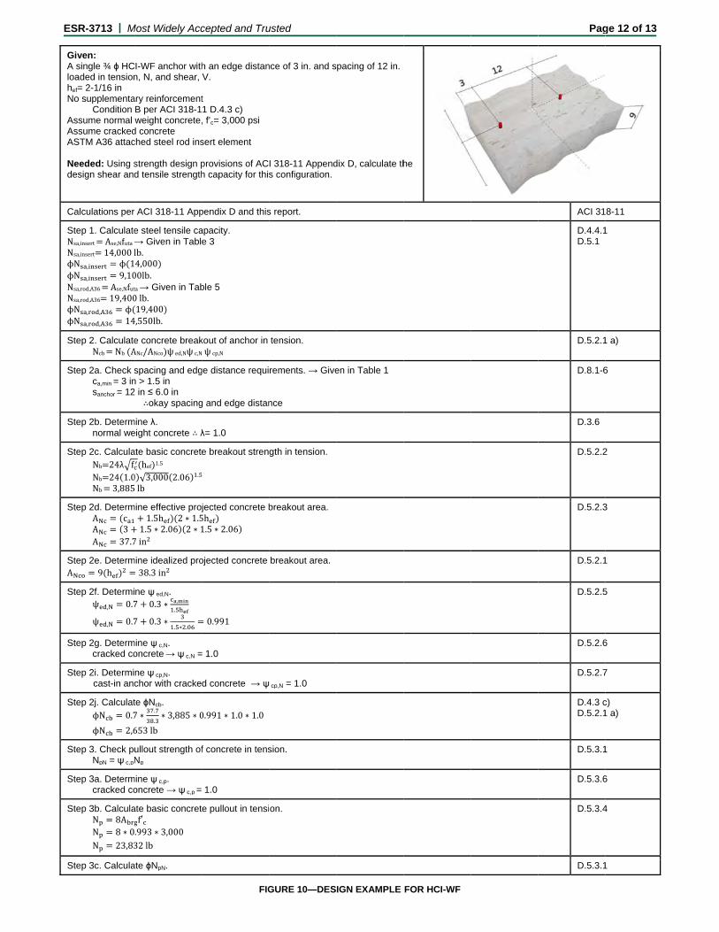
Given: A single ¾ ϕ HCloaded in tensionhef= 2-1/16 in No supplementa
Condition Assume normal Assume crackedASTM A36 attac
Needed: Using sdesign shear and
Calculations per
Step 1. CalculateNsa,insert Ase,Nfuta Nsa,insert 14,000lϕN , ϕ 1ϕN , 9,10Nsa,rod,A36 Ase,NfutNsa,rod,A36 19,400ϕN , , ϕϕN , , 14
Step 2. CalculateNcb Nb A
Step 2a. Check sca,min = 3 insanchor = 12
Step 2b. Determnormal we
Step 2c. CalculaNb 24λ fNb 24 1.0Nb 3,885
Step 2d. DetermA cA 3A 37.7
Step 2e. DetermA 9 h
Step 2f. Determiψ , 0.7
ψ , 0.7
Step 2g. Determcracked co
Step 2i. Determi cast-in anc
Step 2j. CalculatϕN 0.7
ϕN 2,6
Step 3. Check pNpN = ψ c,pN
Step 3a. Determcracked co
Step 3b. CalculaN 8AN 8 ∗ 0N 23,83
Step 3c. Calcula
Most Widely Acc
I-WF anchor withn, N, and shear,
ary reinforcementB per ACI 318-1weight concrete,
d concrete ched steel rod ins
strength design pd tensile strength
r ACI 318-11 App
e steel tensile ca→ Given in Tabllb.4,000 00lb. ta → Given in Tab0lb.19,400 4,550lb.
e concrete breakANc/ANco ψed,Nψc,N
spacing and edgn > 1.5 in 2 in ≤ 6.0 in
∴okay spacing
mine λ. eight concrete ∴ λ
ate basic concretehef 1.5
0 √3,000 2.06 .
lb
mine effective proj1.5h 2 ∗ 1.5
1.5 ∗ 2.06 2 ∗ 17in
mine idealized pro38.3in
ne ψ ed,N. 7 0.3 ∗ ,
.
7 0.3 ∗. ∗ .
mine ψ c,N. oncrete → ψ c,N =
ne ψ cp,N. chor with cracke
te ϕNcb. 7 ∗
.
.∗ 3,885 ∗ 0
653lb
ullout strength ofNp
mine ψ c,p. oncrete → ψ c,p =
ate basic concretf′ .993 ∗ 3,000
32lb
ate ϕNpN.
cepted and Tru
h an edge distanV.
t 1 D.4.3 c) , f’c= 3,000 psi
sert element
provisions of ACh capacity for this
pendix D and this
apacity. e 3
ble 5
kout of anchor in Nψcp,N
ge distance requi
g and edge distan
λ= 1.0
e breakout stren
jected concrete b5h 1.5 ∗ 2.06
ojected concrete
0.991
= 1.0
d concrete → ψ
0.991 ∗ 1.0 ∗ 1.0
f concrete in tens
1.0
e pullout in tensi
FIG
usted
nce of 3 in. and s
I 318-11 Appends configuration.
s report.
tension.
rements. → Give
nce
gth in tension.
breakout area.
breakout area.
cp,N = 1.0
sion.
on.
GURE 10—DES
pacing of 12 in.
dix D, calculate th
en in Table 1
IGN EXAMPLE
he
FOR HCI-WF
Pag
ACI 31
D.4.4.1D.5.1
D.5.2.1
D.8.1-6
D.3.6
D.5.2.2
D.5.2.3
D.5.2.1
D.5.2.5
D.5.2.6
D.5.2.7
D.4.3 cD.5.2.1
D.5.3.1
D.5.3.6
D.5.3.4
D.5.3.1
ge 12 of 13
8-11
1
1 a)
6
2
3
1
5
6
7
c) 1 a)
1
6
4
1
ESR-3713 | Most Widely Accepted and Trusted Page 13 of 13
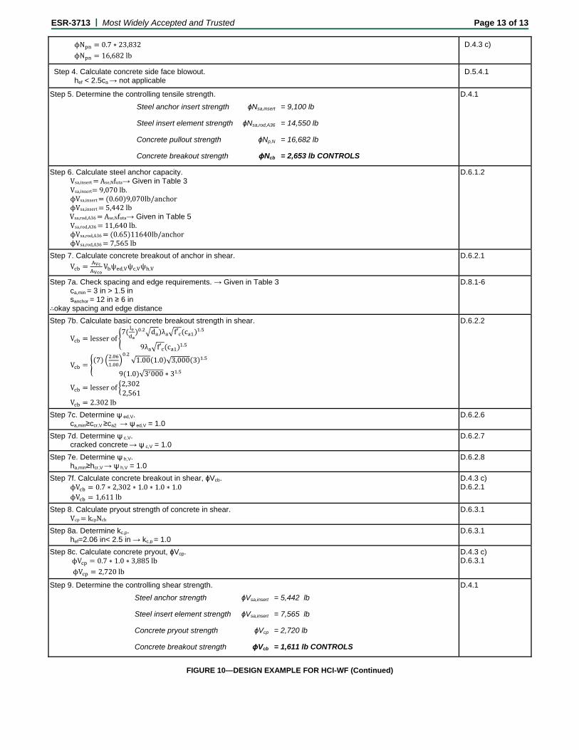
ϕN 0.7 ∗ 23,832
ϕN 16,682lb
D.4.3 c)
Step 4. Calculate concrete side face blowout. hef < 2.5ca → not applicable
D.5.4.1
Step 5. Determine the controlling tensile strength.
Steel anchor insert strength ϕNsa,insert = 9,100 lb
Steel insert element strength ϕNsa,rod,A36 = 14,550 lb
Concrete pullout strength ϕNp,N = 16,682 lb
Concrete breakout strength ϕNcb = 2,653 lb CONTROLS
D.4.1
Step 6. Calculate steel anchor capacity. Vsa,insert Ase,Nfuta→ Given in Table 3 Vsa,insert 9,070lb. ϕVsa,insert 0.60 9,070lb/anchor ϕVsa,insert 5,442lbVsa,rod,A36 Ase,Nfuta→ Given in Table 5 Vsa,rod,A36 11,640lb. ϕVsa,rod,A36 0.65 11640lb/anchor ϕVsa,rod,A36 7,565lb
D.6.1.2
Step 7. Calculate concrete breakout of anchor in shear.
V V ψ , ψ , ψ ,
D.6.2.1
Step 7a. Check spacing and edge requirements. → Given in Table 3 ca,min = 3 in > 1.5 in sanchor = 12 in ≥ 6 in ∴okay spacing and edge distance
D.8.1-6
Step 7b. Calculate basic concrete breakout strength in shear.
V lesserof7 . d λ f′ c .
9λ f′ c .
V7
.
.
.√1.00 1.0 √3,000 3 .
9 1.0 √3 000 ∗ 3 .
V lesserof 2,3022,561
V 2.302lb
D.6.2.2
Step 7c. Determine ψ ed,V. ca,min≥ccr,V ≥ca2 → ψ ed,V = 1.0
D.6.2.6
Step 7d. Determine ψ c,V. cracked concrete → ψ c,V = 1.0
D.6.2.7
Step 7e. Determine ψ h,V. ha,min≥hcr,V → ψ h,V = 1.0
D.6.2.8
Step 7f. Calculate concrete breakout in shear, ϕVcb. ϕV 0.7 ∗ 2,302 ∗ 1.0 ∗ 1.0 ∗ 1.0 ϕV 1,611lb
D.4.3 c) D.6.2.1
Step 8. Calculate pryout strength of concrete in shear. Vcp kcpNcb
D.6.3.1
Step 8a. Determine kc,p. hef=2.06 in< 2.5 in → kc,p = 1.0
D.6.3.1
Step 8c. Calculate concrete pryout, ϕVcp. ϕV 0.7 ∗ 1.0 ∗ 3,885lb
ϕV 2,720lb
D.4.3 c) D.6.3.1
Step 9. Determine the controlling shear strength.
Steel anchor strength ϕVsa,insert = 5,442 lb
Steel insert element strength ϕVsa,insert = 7,565 lb
Concrete pryout strength ϕVcp = 2,720 lb
Concrete breakout strength ϕVcb = 1,611 lb CONTROLS
D.4.1
FIGURE 10—DESIGN EXAMPLE FOR HCI-WF (Continued)

ICC-ES Evaluation Reports are not to be construed as representing aesthetics or any other attributes not specifically addressed, nor are they to be construed as an endorsement of the subject of the report or a recommendation for its use. There is no warranty by ICC Evaluation Service, LLC, express or implied, as to any finding or other matter in this report, or as to any product covered by the report.
Copyright © 2015 Page 1 of 1 1000
ICC-ES Evaluation Report ESR-3713 FBC Supplement Issued July 2015 This report is subject to renewal July 2016.
www.icc-es.org | (800) 423-6587 | (562) 699-0543 A Subsidiary of the International Code Council ®
DIVISION: 03 00 00—CONCRETE Section: 03 15 19—Cast-in Concrete Anchors Section: 03 16 00—Concrete Anchors REPORT HOLDER: HILTI, INC. 7250 DALLAS PARKWAY, SUITE 1000 PLANO, TEXAS 75024 (800) 879-8000 www.us.hilti.com [email protected] EVALUATION SUBJECT: HILTI HCI-WF AND HCI-MD HEADED CAST-IN SPECIALTY INSERTS IN CRACKED AND UNCRACKED CONCRETE 1.0 REPORT PURPOSE AND SCOPE
Purpose:
The purpose of this evaluation report supplement is to indicate that the HILTI HCI-WF and HCI-MD Headed Cast-In Specialty Inserts in Cracked and Uncracked Concrete, recognized in ICC-ES master evaluation report ESR-3713, has also been evaluated for compliance with the codes noted below.
Applicable code editions:
2014 Florida Building Code—Building
2014 Florida Building Code—Residential
2.0 CONCLUSIONS
The HILTI HCI-WF and HCI-MD Headed Cast-In Specialty Inserts in Cracked and Uncracked Concrete, described in Sections 2.0 through 7.0 of the master evaluation report ESR-3713, comply with the 2014 Florida Building Code—Building and the 2014 Florida Building Code—Residential, when designed and installed in accordance with the 2012 International Building Code® provisions noted in the master report, and under the following conditions:
Design wind loads must be based on Section 1609 of the 2014 Florida Building Code—Building or Section 301.2.1.1 of the 2014 Florida Building Code—Residential, as applicable.
Load combinations must be in accordance with Section 1605.2 or Section 1605.3 of the 2014 Florida Building Code—Building, as applicable.
Use of the HILTI HCI-WF and HCI-MD Headed Cast-In Specialty Inserts in Cracked and Uncracked Concrete, for compliance with the High-Velocity Hurricane Zone Provisions of the 2014 Florida Building Code—Building and 2014 Florida Building Code—Residential, has not been evaluated and is outside the scope of this supplement.
For products falling under Florida Rule 9N-3, verification that the report holder’s quality-assurance program is audited by a quality-assurance entity approved by the Florida Building Commission for the type of inspections being conducted is the responsibility of an approved validation entity (or the code official when the report holder does not possess an approval by the Commission).
This supplement expires concurrently with the master report, issued July 2015.


![APPLIED PROBABILITY AND STATISTICS FOR …ace.cs.ohiou.edu/~chelberg/classes/3713/ch03-4.pdf · APPLIED PROBABILITY AND STATISTICS FOR ELECTRICAL ENGINEERS Chapter 3 E[Y] ... Otherwise,](https://img.pdfslide.us/doc/110x75/5a90570e7f8b9a78648e0da3/applied-probability-and-statistics-for-acecsohioueduchelbergclasses3713ch03-4pdfapplied.jpg)