Embed Size (px)
Citation preview
ICC-ES Evaluation Reports are not to be construed as representing aesthetics or any other attributes not specifically addressed, nor are they to be construed as an endorsement of the subject of the report or a recommendation for its use. There is no warranty by ICC Evaluation Service, LLC, express or implied, as to any finding or other matter in this report, or as to any product covered by the report.
Copyright © 2019 ICC Evaluation Service, LLC. All rights reserved. Page 1 of 12
ICC-ES Evaluation Report ESR-1970 Reissued June 2018
Revised December 2019
This report is subject to renewal June 2020.
www.icc-es.org | (800) 423-6587 | (562) 699-0543 A Subsidiary of the International Code Council ®
DIVISION: 03 00 00—CONCRETE Section: 03 16 00—Concrete Anchors DIVISION: 05 00 00—METALS Section: 05 05 19—Post-installed Concrete Anchors REPORT HOLDER:
MiTek USA, INC. (FORMERLY USP STRUCTURAL CONNECTORS)
16023 SWINGLEY RIDGE ROAD CHESTERFIELD, MISSOURI 63017 (800) 328-5934 www.mitek-us.com [email protected]
EVALUATION SUBJECT:
DUC UNDERCUT ANCHORS 1.0 EVALUATION SCOPE
Compliance with the following codes:
2018, 2015, 2012, 2009, and 2006 International Building Code® (IBC)
2018, 2015, 2012, 2009, and 2006 International Residential Code® (IRC)
For evaluation for compliance with codes adopted by the Los Angeles Department of Building and Safety (LADBS), see ESR-1970 LABC and LARC Supplement.
Property evaluated:
Structural
2.0 USES
The MiTek USP DUC Undercut Anchor is used to resist static, wind, and seismic tension and shear loads in cracked and uncracked normal-weight and lightweight concrete having a specified compressive strength, f′c, of 2,500 psi to 8,500 psi (17.2 MPa to 58.6 MPa). The DUC anchors comply as anchors installed in hardened concrete as described in Section 1901.3 of the 2018 and 2015 IBC, Section 1909 of the 2012 IBC, and Section 1912 of the 2009 and 2006 IBC. The anchors are an alternative to cast-in-place anchors described in Section 1908 of the 2012 IBC, and Section 1911 of the 2009 and 2006 IBC. The anchors may also be used where an engineered design is submitted in accordance with Section R301.1.3 of the IRC.
3.0 DESCRIPTION
3.1 General:
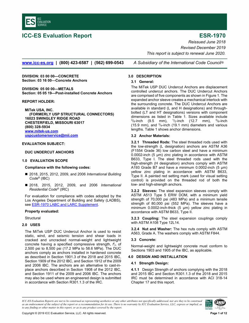
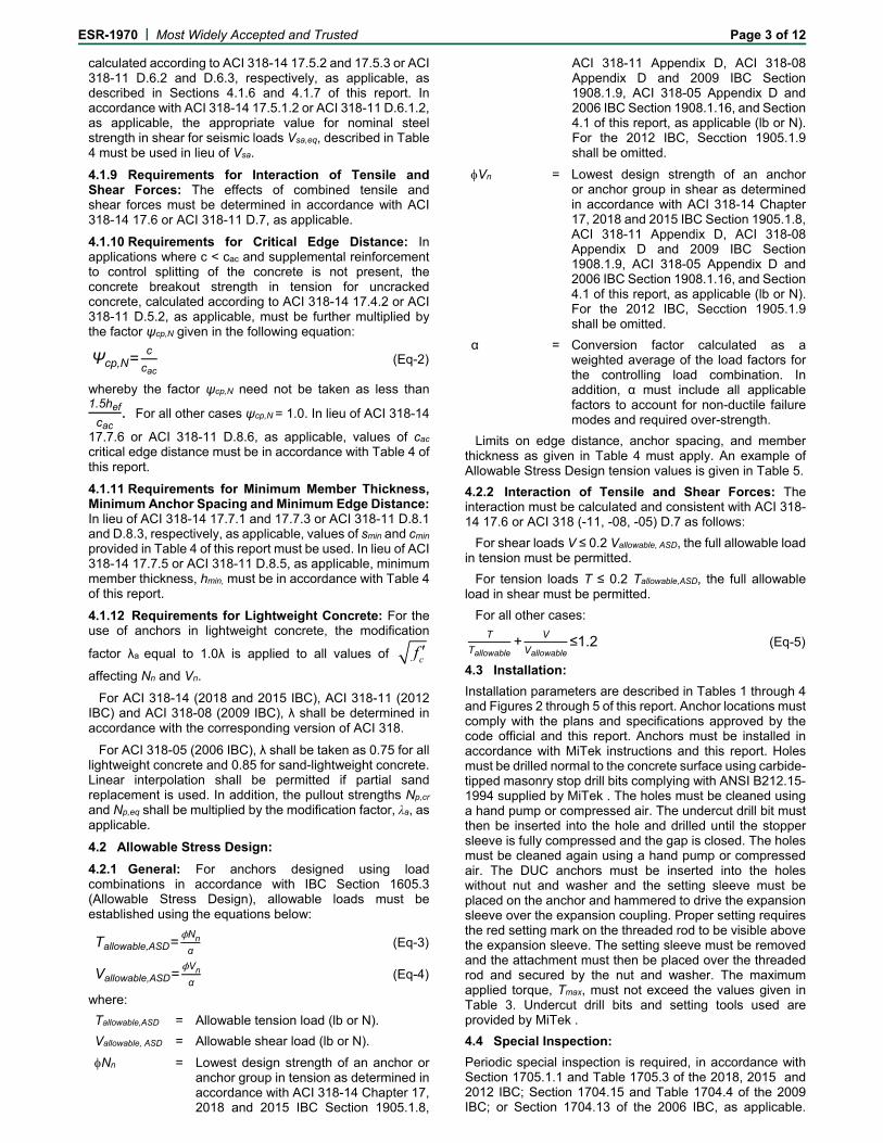
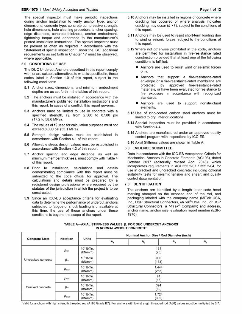
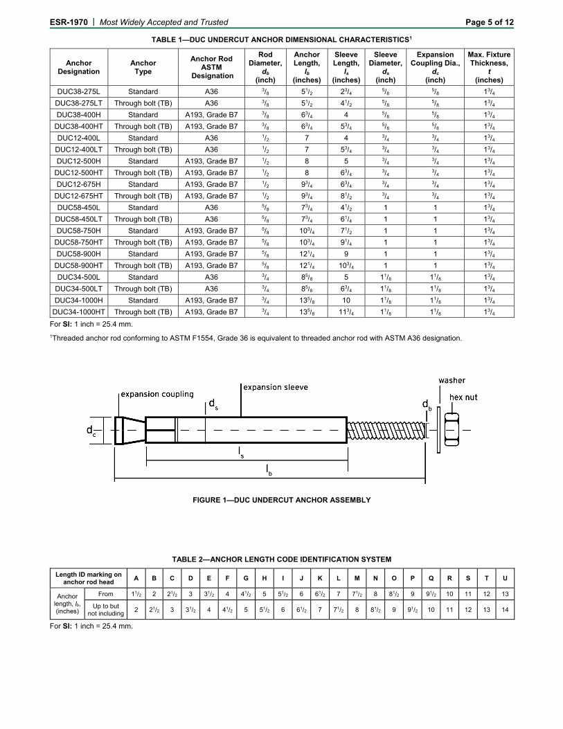
The MiTek USP DUC Undercut Anchors are displacement controlled undercut anchors. The DUC Undercut Anchors are comprised of five components as shown in Figure 1. The expanded anchor sleeve creates a mechanical interlock with the surrounding concrete. The DUC Undercut Anchors are available in standard (L and H designations) and through-bolted (LT and HT designations) versions with component dimensions as listed in Table 1. Sizes available include 3/8-inch (9.5 mm), 1/2-inch (12.7 mm), 5/8-inch (15.9 mm), and 3/4-inch (19.1 mm) diameters and various lengths. Table 1 shows anchor dimensions.
3.2 Anchor Materials:
3.2.1 Threaded Rods: The steel threaded rods used with the low-strength (L designation) anchors are ASTM A36 (F1554 Grade 36) low carbon steel and have a minimum 0.0002-inch (5 µm) zinc plating in accordance with ASTM B633, Type I. The steel threaded rods used with the high-strength (H designation) anchors comply with ASTM A193 Grade B7 and have a minimum 0.0002-inch (5 µm) yellow zinc plating in accordance with ASTM B633, Type II. A painted red setting mark (used for visual setting control) is provided on the threaded rod of both the low- and high-strength anchors.
3.2.2 Sleeves: The steel expansion sleeves comply with ASTM A513 Type 5 ERW DOM, with a minimum yield strength of 70,000 psi (483 MPa) and a minimum tensile strength of 80,000 psi (552 MPa). The sleeves have a minimum 0.0002-inch-thick (5 µm) yellow zinc plating in accordance with ASTM B633, Type II.
3.2.3 Coupling: The steel expansion couplings comply with ASTM A108 Type 12L14.
3.2.4 Nut and Washer: The hex nuts comply with ASTM A563, Grade A. The washers comply with ASTM F844.
3.3 Concrete:
Normal-weight and lightweight concrete must conform to Sections 1903 and 1905 of the IBC, as applicable.
4.0 DESIGN AND INSTALLATION
4.1 Strength Design:
4.1.1 Design Strength of anchors complying with the 2018 and 2015 IBC and Section R301.1.3 of the 2018 and 2015 IRC must be determined in accordance with ACI 318-14 Chapter 17 and this report.
ESR-1970 | Most Widely Accepted and Trusted Page 2 of 12
Design strength of anchors complying with the 2012 IBC and Section R301.1.3 of the 2012 IRC, must be determined in accordance with ACI 318-11 Appendix D and this report.
Design strength of anchors complying with the 2009 IBC and Section R301.1.3 of 2009 IRC must be in accordance with ACI 318-08 Appendix D and this report.
Design strength of anchors complying with the 2006 IBC and Section R301.1.3 of 2006 IRC must be in accordance with ACI 318-05 Appendix D and this report.
Design examples according to the 2018, 2015 and 2012 IBC are given in Figures 5, 6, and 7 of this report. Design parameters are described in Tables 4 and 5 of this report and are based on the 2018 and 2015 IBC (ACI 318-14) and 2012 IBC (ACI 318-11) unless noted otherwise in Sections 4.1.1 through 4.1.12. The strength design of anchors must comply with ACI 318-14 17.3.1 or ACI 318-11 D.4.1, except as required in ACI 318-14 17.2.3 or ACI 318-11 D.3.3, as applicable.
Strength reduction factors, , as given in ACI 318-14 17.3.3 or ACI 318-11 D.4.3, as applicable, and Table 4 must be used for load combinations calculated in accordance with Section 1605.2 of the IBC and Section 5.3 of ACI 318-14 or Section 9.2 of ACI 318-11, as applicalbe. Strength reduction factors, , as given in ACI 318-11 D.4.4 must be used for load combinations calculated in accordance with ACI 318-11 Appendix C.
The value of f′c used in the calculations must be limited to a maximum of 8,000 psi (55.2 MPa), in accordance with ACI 318-14 17.2.7 or ACI 318-11 D.3.7.
4.1.2 Requirements for Static Steel Strength in Tension, Nsa: The nominal steel strength of a single anchor in tension, Nsa, must be calculated in accordance with ACI 318-14 17.4.1.2 or ACI 318-11 D.5.1.2, as applicable. The resulting values of Nsa are described in Table 4 of this report. Strength reduction factors, , corresponding to ductile steel elements may be used.
4.1.3 Requirements for Static Concrete Breakout Strength in Tension, Ncb or Ncbg: The nominal concrete breakout strength of a single anchor or group of anchors in tension, Ncb and Ncbg, respectively, must be calculated in accordance with ACI 318-14 17.4.2 or ACI 318-11 D.5.2, as applicable, and modifications as described in this section. The basic concrete breakout strength of a single anchor in tension in regions where analysis indicates cracking, Nb, must be calculated according to ACI 318-14 17.4.2.2 or ACI 318-11 D.5.2.2, as applicable, using the values of hef and kcr as described in Table 4 of this report. Concrete breakout strength in tension in regions where analysis indicates no cracking in accordance with ACI 318-14 17.4.2.6 or ACI 318-11 D.5.2.6, as applicable, must be calculated with Ψc,N = 1.0 and using the value of kuncr as given in Table 4 of this report.
4.1.4 Requirements for Static Pullout Strength in Tension, Npn: The nominal pullout strength of a single anchor or a group of anchors in tension, in accordance with ACI 318-14 17.4.3 or ACI 318-11 D.5.3, as applicable, in cracked concrete, Np,cr, is given in Table 4 of this report. For all design cases, Ψc,P =1.0. In accordance with ACI 318-14 17.4.3.2 or ACI 318-11 D.5.3.2, as applicable, the nominal pullout strength in cracked concrete must be adjusted by calculation according to Eq-1:
, , , (lb, psi) (Eq-1)
, , . (N, MPa)
In uncracked concrete, pullout strength does not control and therefore need not be evaluated.
4.1.5 Requirements for Static Steel Strength in Shear, Vsa: The nominal steel strength in shear, Vsa, of a single anchor in accordance with ACI 318-14 17.5.1.2 or ACI 318-11 D.6.1.2, as applicable, is given in Table 4 for the standard type and through-bolt type anchors and must be used in lieu of the values derived by calculation from ACI 318-14 Eq. 17.5.1.2b or ACI 318-11 Eq. D-29, as applicable. Strength reduction factors, , corresponding to ductile steel elements must be used.
4.1.6 Requirements for Static Concrete Breakout Strength in Shear, Vcb or Vcbg: The nominal static concrete breakout strength of a single anchor or a group of anchors in shear, Vcb or Vcbg, respectively, must be calculated in accordance with ACI 318-14 17.5.2 or ACI 318-11 D.6.2, as applicable, with modifications as described in this section. The basic concrete breakout strength of a single anchor in shear must be calculated in accordance with ACI 318-14 17.5.2.2 or ACI 318-11 D.6.2.2, as applicable, where the value of le used in ACI 318-14 Eq. 17.5.2.2a or ACI 318-11 Eq. D-33 must be taken as hef, but no greater than 8da, for the anchors with one tubular shell over full length of the embedment depth; or the value of le used in ACI 318-14 Eq. 17.5.2.2a or ACI 318-11 Eq. D-33 must be taken as 2da for the anchors with a distance sleeve separated from the expansion sleeve.
4.1.7 Requirements for Static Concrete Pryout Strength in Shear, Vcp or Vcpg: The nominal static concrete pryout strength of a single anchor or a group of anchors in shear, Vcp or Vcpg, respectively, must be calculated in accordance with ACI 318-14 17.5.3 or ACI 318-11 D.6.3, as applicable, modified by using the value kcp provided in Table 4 and the value Ncb and Ncbg as calculated in Section 4.1.3 of this report.
4.1.8 Requirements for Seismic Design: General: For load combinations including seismic, the design must be performed in accordance with ACI 318-14 17.2.3 or ACI 318-11 D.3.3, as applicable. Modifications to ACI 318-14 17.2.3 shall be applied under Section 1905.1.8 of the 2018 and 2015 IBC. For the 2012 IBC, Section 1905.1.9 shall be omitted. Modifications to ACI 318 (-08, -05) D.3.3 must be applied under Section 1908.1.9 of the 2009 IBC or Section 1908.1.16 of the 2006 IBC, as applicable.
The L, LT, H, and HT designated anchors comply with ACI 318-14 2.3 or ACI 318-11 D.1, as applicable, as ductile steel elements and must be designed in accordance with ACI 318-14, 17.2.3.4, 17.2.3.5, 17.2.3.6 or 17.2.3.7; ACI 318-11 D.3.3.4, D.3.3.5, D.3.3.6, and D.3.3.7; ACI 318-08 D.3.3.4, D.3.3.5, or D.3.3.6; or ACI 318-05 D.3.3.4 or D.3.3.5, as applicable.
4.1.8.1 Seismic Tension: The nominal steel strength and nominal concrete breakout strength for anchors in tension must be calculated in accordance with ACI 318-14 17.4.1 and 17.4.2 or ACI 318-11 D.5.1 and D.5.2, respectively, as applicable, as described in Sections 4.1.2 and 4.1.3 of this report. In accordance with ACI 318-14 17.4.3.2 or ACI 318-11 D.5.3.2, as applicable, the appropriate value for pullout strength in tension for seismic loads, Np,eq, described in Table 4 of this report must be used in lieu of Np. Np,eq may be adjusted by calculations for concrete compressive strength in accordance with Eq-1 of this report.
4.1.8.2 Seismic Shear: The nominal concrete breakout strength and pryout strength for anchors in shear must be
ESR-1970 | Most Widely Accepted and Trusted Page 3 of 12
calculated according to ACI 318-14 17.5.2 and 17.5.3 or ACI 318-11 D.6.2 and D.6.3, respectively, as applicable, as described in Sections 4.1.6 and 4.1.7 of this report. In accordance with ACI 318-14 17.5.1.2 or ACI 318-11 D.6.1.2, as applicable, the appropriate value for nominal steel strength in shear for seismic loads Vsa,eq, described in Table 4 must be used in lieu of Vsa.
4.1.9 Requirements for Interaction of Tensile and Shear Forces: The effects of combined tensile and shear forces must be determined in accordance with ACI 318-14 17.6 or ACI 318-11 D.7, as applicable.
4.1.10 Requirements for Critical Edge Distance: In applications where c < cac and supplemental reinforcement to control splitting of the concrete is not present, the concrete breakout strength in tension for uncracked concrete, calculated according to ACI 318-14 17.4.2 or ACI 318-11 D.5.2, as applicable, must be further multiplied by the factor ψcp,N given in the following equation:
Ψcp,N=c
cac (Eq-2)
whereby the factor ψcp,N need not be taken as less than 1.5hef
cac. For all other cases ψcp,N = 1.0. In lieu of ACI 318-14
17.7.6 or ACI 318-11 D.8.6, as applicable, values of cac critical edge distance must be in accordance with Table 4 of this report.
4.1.11 Requirements for Minimum Member Thickness, Minimum Anchor Spacing and Minimum Edge Distance: In lieu of ACI 318-14 17.7.1 and 17.7.3 or ACI 318-11 D.8.1 and D.8.3, respectively, as applicable, values of smin and cmin provided in Table 4 of this report must be used. In lieu of ACI 318-14 17.7.5 or ACI 318-11 D.8.5, as applicable, minimum member thickness, hmin, must be in accordance with Table 4 of this report.
4.1.12 Requirements for Lightweight Concrete: For the use of anchors in lightweight concrete, the modification
factor λa equal to 1.0λ is applied to all values of cf
affecting Nn and Vn.
For ACI 318-14 (2018 and 2015 IBC), ACI 318-11 (2012 IBC) and ACI 318-08 (2009 IBC), λ shall be determined in accordance with the corresponding version of ACI 318.
For ACI 318-05 (2006 IBC), λ shall be taken as 0.75 for all lightweight concrete and 0.85 for sand-lightweight concrete. Linear interpolation shall be permitted if partial sand replacement is used. In addition, the pullout strengths Np,cr and Np,eq shall be multiplied by the modification factor, λa, as applicable.
4.2 Allowable Stress Design:
4.2.1 General: For anchors designed using load combinations in accordance with IBC Section 1605.3 (Allowable Stress Design), allowable loads must be established using the equations below:
Tallowable,ASD=ϕNn
α (Eq-3)
Vallowable,ASD=ϕVn
α (Eq-4)
where:
Tallowable,ASD = Allowable tension load (lb or N).
Vallowable, ASD = Allowable shear load (lb or N).
Nn = Lowest design strength of an anchor or anchor group in tension as determined in accordance with ACI 318-14 Chapter 17, 2018 and 2015 IBC Section 1905.1.8,
ACI 318-11 Appendix D, ACI 318-08 Appendix D and 2009 IBC Section 1908.1.9, ACI 318-05 Appendix D and 2006 IBC Section 1908.1.16, and Section 4.1 of this report, as applicable (lb or N). For the 2012 IBC, Secction 1905.1.9 shall be omitted.
Vn = Lowest design strength of an anchor or anchor group in shear as determined in accordance with ACI 318-14 Chapter 17, 2018 and 2015 IBC Section 1905.1.8, ACI 318-11 Appendix D, ACI 318-08 Appendix D and 2009 IBC Section 1908.1.9, ACI 318-05 Appendix D and 2006 IBC Section 1908.1.16, and Section 4.1 of this report, as applicable (lb or N). For the 2012 IBC, Secction 1905.1.9 shall be omitted.
α = Conversion factor calculated as a weighted average of the load factors for the controlling load combination. In addition, α must include all applicable factors to account for non-ductile failure modes and required over-strength.
Limits on edge distance, anchor spacing, and member thickness as given in Table 4 must apply. An example of Allowable Stress Design tension values is given in Table 5.
4.2.2 Interaction of Tensile and Shear Forces: The interaction must be calculated and consistent with ACI 318-14 17.6 or ACI 318 (-11, -08, -05) D.7 as follows:
For shear loads V ≤ 0.2 Vallowable, ASD, the full allowable load in tension must be permitted.
For tension loads T ≤ 0.2 Tallowable,ASD, the full allowable load in shear must be permitted.
For all other cases:
T
Tallowable+
V
Vallowable≤1.2 (Eq-5)
4.3 Installation:
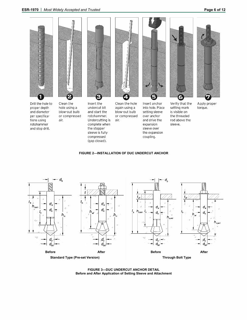
Installation parameters are described in Tables 1 through 4 and Figures 2 through 5 of this report. Anchor locations must comply with the plans and specifications approved by the code official and this report. Anchors must be installed in accordance with MiTek instructions and this report. Holes must be drilled normal to the concrete surface using carbide-tipped masonry stop drill bits complying with ANSI B212.15-1994 supplied by MiTek . The holes must be cleaned using a hand pump or compressed air. The undercut drill bit must then be inserted into the hole and drilled until the stopper sleeve is fully compressed and the gap is closed. The holes must be cleaned again using a hand pump or compressed air. The DUC anchors must be inserted into the holes without nut and washer and the setting sleeve must be placed on the anchor and hammered to drive the expansion sleeve over the expansion coupling. Proper setting requires the red setting mark on the threaded rod to be visible above the expansion sleeve. The setting sleeve must be removed and the attachment must then be placed over the threaded rod and secured by the nut and washer. The maximum applied torque, Tmax, must not exceed the values given in Table 3. Undercut drill bits and setting tools used are provided by MiTek .
4.4 Special Inspection:
Periodic special inspection is required, in accordance with Section 1705.1.1 and Table 1705.3 of the 2018, 2015 and 2012 IBC; Section 1704.15 and Table 1704.4 of the 2009 IBC; or Section 1704.13 of the 2006 IBC, as applicable.
ESR-1970 | Most Widely Accepted and Trusted Page 4 of 12
The special inspector must make periodic inspections during anchor installation to verify anchor type, anchor dimensions, concrete type, concrete compressive strength, hole dimensions, hole cleaning procedure, anchor spacing, edge distances, concrete thickness, anchor embedment, tightening torque and adherence to the manufacturer’s printed installation instructions. The special inspector must be present as often as required in accordance with the “statement of special inspection.” Under the IBC, additional requirements as set forth in Chapter 17 must be observed, where applicable.
5.0 CONDITIONS OF USE
The DUC Undercut Anchors described in this report comply with, or are suitable alternatives to what is specified in, those codes listed in Section 1.0 of this report, subject to the following conditions:
5.1 Anchor sizes, dimensions, and minimum embedment depths are as set forth in the tables of this report.
5.2 The anchors must be installed in accordance with the manufacturer’s published installation instructions and this report. In cases of a conflict, this report governs.
5.3 Anchors must be limited to use in concrete with a specified strength, f′c, from 2,500 to 8,500 psi (17.2 to 58.6 MPa).
5.4 The values of f′c used for calculation purposes must not exceed 8,000 psi (55.1 MPa).
5.5 Strength design values must be established in accordance with Section 4.1 of this report.
5.6 Allowable stress design values must be established in accordance with Section 4.2 of this report.
5.7 Anchor spacing and edge distance, as well as minimum member thickness, must comply with Table 4 of this report.
5.8 Prior to installation, calculations and details demonstrating compliance with this report must be submitted to the code official for approval. The calculations and details must be prepared by a registered design professional where required by the statutes of the jurisdiction in which the project is to be constructed.
5.9 Since an ICC-ES acceptance criteria for evaluating data to determine the performance of undercut anchors subjected to fatigue or shock loading is unavailable at this time, the use of these anchors under these conditions is beyond the scope of the report.
5.10 Anchors may be installed in regions of concrete where cracking has occurred or where analysis indicates cracking may occur (ft > fr), subject to the conditions of this report.
5.11 Anchors may be used to resist short-term loading due to wind or seismic forces, subject to the conditions of this report.
5.12 Where not otherwise prohibited in the code, anchors are permitted for installation in fire-resistance rated construction provided that at least one of the following conditions is fulfilled:
Anchors are used to resist wind or seismic forces only.
Anchors that support a fire-resistance-rated envelope or a fire-resistance-rated membrane are protected by approved fire-resistance-rated materials, or have been evaluated for resistance to fire exposure in accordance with recognized standards.
Anchors are used to support nonstructural elements.
5.13 Use of zinc-coated carbon steel anchors must be limited to dry, interior locations.
5.14 Special inspection must be provided in accordance with Section 4.4.
5.15 Anchors are manufactured under an approved quality control program with inspections by ICC-ES.
5.16 Axial Stiffness values are shown in Table A.
6.0 EVIDENCE SUBMITTED
Data in accordance with the ICC-ES Acceptance Criteria for Mechanical Anchors in Concrete Elements (AC193), dated October 2017 (editorially revised April 2018), which incorporates requirements in ACI 355.2-07 / 355.2-04, for use in cracked and uncracked concrete; including optional suitability tests for seismic tension and shear; and quality control documentation.
7.0 IDENTIFICATION
The anchors are identified by a length letter code head marking stamped on the exposed end of the rod, and packaging labeled with the company name (MiTek USA, Inc., USP Structural Connectors, MiTek® USA, Inc., or USP Structural Connectors, a MiTek® Company) and address, anchor name, anchor size, evaluation report number (ESR-1970).
TABLE A—AXIAL STIFFNESS VALUES, , FOR DUC UNDERCUT ANCHORS
IN NORMAL-WEIGHT CONCRETE1
Concrete State Notation Units Nominal Anchor Size / Rod Diameter (inch)
3/8 1/2 5/8 3/4
Uncracked concrete
βmin 103 lbf/in. (kN/mm)
131 (23)
βm 103 lbf/in. (kN/mm)
930 (163)
βmax 103 lbf/in. (kN/mm)
1,444 (253)
Cracked concrete
βmin 103 lbf/in. (kN/mm)
91 (16)
βm 103 lbf/in. (kN/mm)
394 (69)
βmax 103 lbf/in. (kN/mm)
1,724 (302)
1Valid for anchors with high strength threaded rod (A193 Grade B7). For anchors with low strength threaded rod (A36) values must be multiplied by 0.7.
ESR-1970 | Most Widely Accepted and Trusted Page 5 of 12
TABLE 1—DUC UNDERCUT ANCHOR DIMENSIONAL CHARACTERISTICS1
Anchor Designation
Anchor Type
Anchor Rod ASTM
Designation
Rod Diameter,
db (inch)
Anchor Length,
lb
(inches)
Sleeve Length,
ls (inches)
Sleeve Diameter,
ds (inch)
Expansion Coupling Dia.,
dc (inch)
Max. Fixture Thickness,
t (inches)
DUC38-275L Standard A36 3/8 51/2 23/4 5/8 5/8 13/4
DUC38-275LT Through bolt (TB) A36 3/8 51/2 41/2 5/8 5/8 13/4
DUC38-400H Standard A193, Grade B7 3/8 63/4 4 5/8 5/8 13/4
DUC38-400HT Through bolt (TB) A193, Grade B7 3/8 63/4 53/4 5/8 5/8 13/4
DUC12-400L Standard A36 1/2 7 4 3/4 3/4 13/4
DUC12-400LT Through bolt (TB) A36 1/2 7 53/4 3/4 3/4 13/4
DUC12-500H Standard A193, Grade B7 1/2 8 5 3/4 3/4 13/4
DUC12-500HT Through bolt (TB) A193, Grade B7 1/2 8 63/4 3/4 3/4 13/4
DUC12-675H Standard A193, Grade B7 1/2 93/4 63/4 3/4 3/4 13/4
DUC12-675HT Through bolt (TB) A193, Grade B7 1/2 93/4 81/2 3/4 3/4 13/4
DUC58-450L Standard A36 5/8 73/4 41/2 1 1 13/4
DUC58-450LT Through bolt (TB) A36 5/8 73/4 61/4 1 1 13/4
DUC58-750H Standard A193, Grade B7 5/8 103/4 71/2 1 1 13/4
DUC58-750HT Through bolt (TB) A193, Grade B7 5/8 103/4 91/4 1 1 13/4
DUC58-900H Standard A193, Grade B7 5/8 121/4 9 1 1 13/4
DUC58-900HT Through bolt (TB) A193, Grade B7 5/8 121/4 103/4 1 1 13/4
DUC34-500L Standard A36 3/4 85/8 5 11/8 11/8 13/4
DUC34-500LT Through bolt (TB) A36 3/4 85/8 63/4 11/8 11/8 13/4
DUC34-1000H Standard A193, Grade B7 3/4 135/8 10 11/8 11/8 13/4
DUC34-1000HT Through bolt (TB) A193, Grade B7 3/4 135/8 113/4 11/8 11/8 13/4
For SI: 1 inch = 25.4 mm.
1Threaded anchor rod conforming to ASTM F1554, Grade 36 is equivalent to threaded anchor rod with ASTM A36 designation.
FIGURE 1—DUC UNDERCUT ANCHOR ASSEMBLY
TABLE 2—ANCHOR LENGTH CODE IDENTIFICATION SYSTEM
Length ID marking on anchor rod head
A B C D E F G H I J K L M N O P Q R S T U
Anchor length, lb, (inches)
From 11/2 2 21/2 3 31/2 4 41/2 5 51/2 6 61/2 7 71/2 8 81/2 9 91/2 10 11 12 13
Up to but not including
2 21/2 3 31/2 4 41/2 5 51/2 6 61/2 7 71/2 8 81/2 9 91/2 10 11 12 13 14
For SI: 1 inch = 25.4 mm.
ESR-1970 | Most Widely Accepted and Trusted Page 6 of 12
FIGURE 2—INSTALLATION OF DUC UNDERCUT ANCHOR
Before After Before After
Standard Type (Pre-set Version) Through Bolt Type
FIGURE 3—DUC UNDERCUT ANCHOR DETAIL Before and After Application of Setting Sleeve and Attachment
ESR-1970 | Most Widely Accepted and Trusted Page 7 of 12
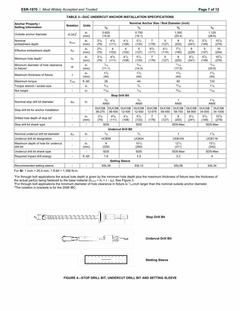
TABLE 3—DUC UNDERCUT ANCHOR INSTALLATION SPECIFICATIONS
Anchor Property / Setting Information
Notation Units Nominal Anchor Size / Rod Diameter (inch)
3/8 1/2 5/8 3/4
Outside anchor diameter da [do]3 in.
(mm) 0.625 (15.9)
0.750 (19.1)
1.000 (25.4)
1.125 (28.6)
Nominal embedment depth
hnom in.
(mm) 31/8 (79)
43/8
(111)41/4
(108)51/4
(133)7
(178)5
(127) 8
(203) 91/2
(241)57/8
(149)107/8
(276)
Effective embedment depth hef in.
(mm) 23/4 (70)
4 (102)
4 (102)
5 (127)
63/4 (171)
41/2 (114)
71/2 (190)
9 (229)
5 (127)
10 (254)
Minimum hole depth1 ho in.
(mm) 31/8 (79)
43/8
(111)41/4
(108)51/4
(133)7
(178)5
(127) 8
(203) 91/2
(241)57/8
(149)107/8
(276)
Minimum diameter of hole clearance in fixture2
dh in.
(mm)
7/16 (11.1)
9/16 (14.3)
11/16 (17.5)
13/16 (20.6)
Maximum thickness of fixture t in.
(mm) 13/4
(44)13/4
(44)13/4
(44) 13/4
(44)
Maximum torque Tmax ft.-lbf. 26 44 60 133
Torque wrench / socket size - in. 9/163/4 15/16 11/8
Nut height - in. 21/647/16
35/64 41/64
Stop Drill Bit
Nominal stop drill bit diameter dbit in. 5/8
ANSI
3/4
ANSI1
ANSI 11/8
ANSI
Stop drill bit for anchor installation - - DUCSB38-275
DUCSB38-400
DUCSB12-400
DUCSB12-500
DUCSB12-675
DUCSB 58-450
DUCSB 58-750
DUCSB58-900
DUCSB34-500
DUCSB34-1000
Drilled hole depth of stop bit1 - in.
(mm) 31/8 (79)
43/8
(111)41/4
(108)51/4
(133)7
(178)5
(127) 8
(203) 91/2
(241)57/8
(149)107/8
(276)
Stop drill bit shank type - - SDS SDS SDS-Max SDS-Max
Undercut Drill Bit
Nominal undercut drill bit diameter duc in. 5/8 3/4 1 11/8
Undercut drill bit designation - - UCB58 UCB34 UCB100 UCB118
Maximum depth of hole for undercut drill bit
- in.
(mm) 9
(229)101/4
(260)121/4
(311) 131/2
(343)
Undercut drill bit shank type - - SDS SDS SDS-Max SDS-Max
Required impact drill energy - ft.-lbf. 1.6 2.5 3.2 4
Setting Sleeve
Recommended setting sleeve - - SSL38 SSL12 SSL58 SSL34
For SI: 1 inch = 25.4 mm, 1 ft-lbf = 1.356 N-m.
1For through bolt applications the actual hole depth is given by the minimum hole depth plus the maximum thickness of fixture less the thickness of the actual part(s) being fastened to the base material (ho,act = ho + t – tpl). See Figure 3. 2For through bolt applications the minimum diameter of hole clearance in fixture is 1/16-inch larger than the nominal outside anchor diameter. 3The notation in brackets is for the 2006 IBC.
Stop
FIGURE 4—STOP DRILL BIT, UNDERCUT DRILL BIT AND SETTING SLEEVE
Undercut Drill Bit
Stop Drill Bit
Stetting Sleeve
ESR-1970 | Most Widely Accepted and Trusted Page 8 of 12
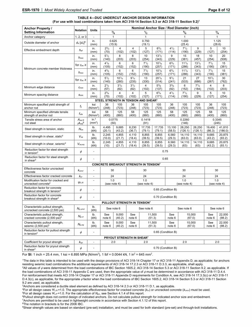
TABLE 4—DUC UNDERCUT ANCHOR DESIGN INFORMATION (For use with load combinations taken from ACI 318-14 Section 5.3 or ACI 318-11 Section 9.2)1
Anchor Property / Setting Information
Notation Units Nominal Anchor Size / Rod Diameter (inch)
3/8 1/2 5/8 3/4Anchor category 1, 2, or 3 - 1 1 1 1
Outside diameter of anchor da [do]8 in.
(mm) 0.625 (15.9)
0.750 (19.1)
1.000 (25.4)
1.125 (28.6)
Effective embedment depth hef in.
(mm) 23/4 (70)
4 (102)
4 (102)
5 (127)
63/4 (171)
41/2 (114)
71/2 (190)
9 (229)
5 (127)
10 (254)
Minimum concrete member thickness
hmin in.
(mm) 51/2
(140)8
(203)8
(203)10
(254)131/2 (343)
9 (229)
15 (381)
18 (457)
10 (254)
20 (508)
for cac ≥ in.
(mm) 41/8
(105)6
(152)6
(152)71/2
(190)101/8 (257)
63/4 (171)
111/4 (286)
131/2 (343)
71/2 (190)
15 (381)
hmin in.
(mm) 43/8
(105)6
(152)6
(152)71/2
(190)101/8 (257)
63/4 (171)
111/4 (286)
131/2 (343)
71/2 (190)
15 (381)
for cac ≥ in.
(mm) 51/2
(140)101/4 (260)
91/4 (235)
13 (330)
201/4 (514)
91/2 (241)
21 (533)
27 (686)
101/2 (267)
30 (762)
Minimum edge distance cmin in.
(mm) 21/4 (57)
31/4 (82)
31/4 (82)
4 (102)
53/8 (137)
33/8 (92)
6 (152)
71/4 (184)
4 (102)
8 (203)
Minimum spacing distance smin in.
(mm) 23/4 (70)
4 (102)
4 (102)
5 (127)
63/4 (171)
41/2 (114)
71/2 (190)
9 (229)
5 (127)
10 (254)
STEEL STRENGTH IN TENSION AND SHEAR3
Minimum specified yield strength of anchor rod fy
ksi (N/mm2)
36 (248)
105 (723)
36 (248)
105 (723)
105 (723)
36 (248)
105 (723)
105 (723)
36 (248)
105 (723)
Minimum specified ultimate tensile strength of anchor rod futa
ksi (N/mm2)
58 (400)
125 (860)
58 (400)
125 (860)
125 (860)
58 (400)
125 (860)
125 (860)
58 (400)
125 (860)
Tensile stress area of anchor rod steel
Ase,N
[Ase]8
in.2 (mm2)
0.0775 (50)
0.1419 (91)
0.2260 (146)
0.3345 (245)
Steel strength in tension, static Nsa lb.
(kN) 4,495 (20.1)
9,685 (43.2)
8,230 (36.7)
17,735 (79.1)
17,735 (79.1)
13,100 (58.5)
28,250 (126.1)
28,250 (126.1)
19,400 (86.3)
41,810 (186.0)
Steel strength in shear, static9 Vsa lb.
(kN) 2,245 (10.0)
4,855 (21.7)
4,110 (18.4)
8,855 (39.5)
8,855 (39.5)
6,560 (29.3)
14,110 (63.0)
14,110 (63.0)
9,685 (43.2)
20,875 (93.2)
Steel strength in shear, seismic9 Vsa,eq lb.
(kN) 2,245 (10)
4,855 (21.7)
4,110 (18.4)
8,855 (39.5)
8,855 (39.5)
6,560 (29.3)
14,110 (63)
14,110 (63)
9,685 (43.2)
20,875 (93.1)
Reduction factor for steel strength in tension2 - 0.75
Reduction factor for steel strength in shear2 - 0.65
CONCRETE BREAKOUT STRENGTH IN TENSION7
Effectiveness factor uncracked concrete kuncr - 30 30 30 30
Effectiveness factor cracked concrete kcr - 24 24 24 24
Modification factor for cracked and uncracked concrete4 ψc,N
- 1.0 (see note 4)
1.0 (see note 4)
1.0 (see note 4)
1.0 (see note 4)
Reduction factor for concrete breakout strength in tension2 - 0.65 (Condition B)
Reduction factor for concrete breakout strength in shear2 - 0.70 (Condition B)
PULLOUT STRENGTH IN TENSION7
Characteristic pullout strength, uncracked concrete (2,500 psi) Np,uncr
lb. (kN)
See note 6 See note 6 See note 6 See note 6
Characteristic pullout strength, cracked concrete (2,500 psi)5 Np,cr
lb. (kN)
See note 6
9,000 (40.2)
See note 6
11,500 (51.3)
See note 6
15,000 (67.0)
See note 6
22,000 (98.2)
Characteristic pullout strength, seismic (2,500 psi)5 Np,eq
lb. (kN)
See note 6
9,000 (40.2)
See note 6
11,500 (51.3)
See note 6
15,000 (67.0)
See note 6
22,000 (98.2)
Reduction factor for pullout strength in tension2 - 0.65 (Condition B)
PRYOUT STRENGTH IN SHEAR7
Coefficient for pryout strength kcp - 2.0 2.0 2.0 2.0
Reduction factor for pryout strength in shear2 - 0.70 (Condition B)
For SI: 1 inch = 25.4 mm, 1 ksi = 6.895 MPa (N/mm2), 1 lbf = 0.0044 kN, 1 in2 = 645 mm2.
1The data in this table is intended to be used with the design provisions of ACI 318-14 Chapter 17 or ACI 318-11 Appendix D, as applicable; for anchors resisting seismic load combinations the additional requirements of ACI 318-14 17.2.3 or ACI 318-11 D.3.3, as applicable, shall apply. 2All values of were determined from the load combinations of IBC Section 1605.2, ACI 318-14 Section 5.3 or ACI 318-11 Section 9.2, as applicable. If the load combinations of ACI 318-11 Appendix C are used, then the appropriate value of must be determined in accordance with ACI 318-11 D.4.4. For reinforcement that meets ACI 318-14 Chapter 17 or ACI 318-11 Appendix D requirements for Condition A, see ACI 318-14 17.3.3(c) or ACI 318-11 D.4.3(c), as applicable, for the appropriate factor when the load combinations of IBC Section 1605.2, ACI 318-14 Section 5.3 or ACI 318-11 Section 9.2 are used, as applicable. 3Anchors are considered a ductile steel element as defined by ACI 318-14 2.3 or ACI 318-11 D.1, as applicable. 4For all design cases Ψc,N =1.0. The appropriate effectiveness factor for cracked concrete (kcr) or uncracked concrete (kuncr) must be used. 5For all design cases Ψc,P =1.0. For the calculation of Npn, see Section 4.1.4 of this report. 6Pullout strength does not control design of indicated anchors. Do not calculate pullout strength for indicated anchor size and embedment. 7Anchors are permitted to be used in lightweight concrete in accordance with Section 4.1.12 of this report. 8The notation in brackets is for the 2006 IBC. 9Shear strength values are based on standard (pre-set) installation, and must be used for both standard (pre-set) and through-bolt installations.
ESR-1970 | Most Widely Accepted and Trusted Page 9 of 12
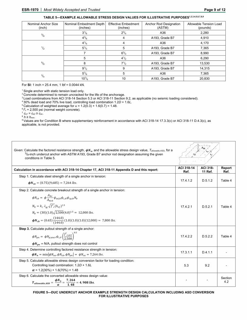
TABLE 5—EXAMPLE ALLOWABLE STRESS DESIGN VALUES FOR ILLUSTRATIVE PURPOSES1,2,3,4,5,6,7,8,9
Nominal Anchor Size (inch)
Nominal Embedment Depth(inches)
Effective Embedment (inches)
Anchor Rod Designation (ASTM)
Allowable Tension Load (pounds)
3/8 31/8 23/4 A36 2,280
43/8 4 A193, Grade B7 4,910
1/2
41/4 4 A36 4,170
51/4 5 A193, Grade B7 7,365
7 63/4 A193, Grade B7 8,990
5/8
5 41/2 A36 6,290
8 71/2 A193, Grade B7 13,530
91/2 9 A193, Grade B7 14,315
3/4 57/8 5 A36 7,365
107/8 10 A193, Grade B7 20,830
For SI: 1 inch = 25.4 mm, 1 lbf = 0.0044 kN.
1 Single anchor with static tension load only. 2 Concrete determined to remain uncracked for the life of the anchorage. 3 Load combinations from ACI 318-14 Section 5.3 or ACI 318-11 Section 9.2, as applicable (no seismic loading considered). 4 30% dead load and 70% live load, controlling load combination 1.2D + 1.6L. 5 Calculation of weighted average for α = 1.2(0.3) + 1.6(0.7) = 1.48. 6 f’c = 2,500 psi (normal weight concrete). 7 ca1 = ca2 ≥ cac. 8 h ≥ hmin. 9 Values are for Condition B where supplementary reinforcement in accordance with ACI 318-14 17.3.3(c) or ACI 318-11 D.4.3(c), as applicable, is not provided.
Given: Calculate the factored resistance strength, , and the allowable stress design value, Tallowable,ASD, for a 3/8-inch undercut anchor with ASTM A193, Grade B7 anchor rod designation assuming the given conditions in Table 5.
Calculation in accordance with ACI 318-14 Chapter 17, ACI 318-11 Appendix D and this report: ACI 318-14
Ref. ACI 318-11 Ref.
Report Ref.
Step 1. Calculate steel strength of a single anchor in tension:
0.75 9,685 7,264 .
17.4.1.2 D.5.1.2 Table 4
Step 2. Calculate concrete breakout strength of a single anchor in tension:
, , ,
′ .
30 1.0 2,500 4.0 . 12,000 .
0.65144.0144.0
1.0 1.0 1.0 12,000 7,800 .
17.4.2.1 D.5.2.1 Table 4
Step 3. Calculate pullout strength of a single anchor:
, ,′ ,2,500
.
N/A, pullout strength does not control
17.4.2.2 D.5.2.2 Table 4
Step 4. Determine controlling factored resistance strength in tension:
min , , 7,264 . 17.3.1.1 D.4.1.1 -
Step 5. Calculate allowable stress design conversion factor for loading condition:
Controlling load combination: 1.2D + 1.6L
= 1.2(30%) + 1.6(70%) = 1.48
5.3 9.2 -
Step 6. Calculate the converted allowable stress design value:
, ,.
, . - -
Section 4.2
FIGURE 5—DUC UNDERCUT ANCHOR EXAMPLE STRENGTH DESIGN CALCULATION INCLUDING ASD CONVERSION
FOR ILLUSTRATIVE PURPOSES
ESR-1970 | Most Widely Accepted and Trusted Page 10 of 12
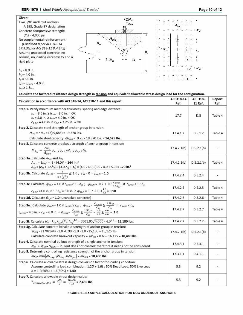
Given: Two 3/8” undercut anchors A 193, Grade B7 designation Concrete compressive strength: (f’c) = 4,000 psi No supplemental reinforcement: (Condition B per ACI 318‐14 17.3.3(c) or ACI 318‐11 D.4.3(c)) Assume uncracked concrete, no seismic, no loading eccentricity and a rigid plate ha = 8.0 in. hef = 4.0 in. sa = 5.0 in. ca1 = ca,min = 4.0 in. ca2 ≥ 1.5ca1
Calculate the factored resistance design strength in tension and equivalent allowable stress design load for the configuration.
Calculation in accordance with ACI 318‐14, ACI 318‐11 and this report: ACI 318‐14
Ref. ACI 318‐11 Ref.
Report Ref.
Step 1. Verify minimum member thickness, spacing and edge distance: ha = 8.0 in. ≥ hmin = 8.0 in. ∴ OK sa = 5.0 in. ≥ smin = 4.0 in. ∴ OK ca,min = 4.0 in. ≥ cmin = 3.25 in. ∴ OK
17.7 D.8 Table 4
Step 2. Calculate steel strength of anchor group in tension:
Nsag = nNsa = (2)(9,685) = 19,370 lbs.
Calculate steel capacity: Nsag = 0.75 • 19,370 lbs. = 14,525 lbs.
17.4.1.2 D.5.1.2 Table 4
Step 3. Calculate concrete breakout strength of anchor group in tension:
, , , , 17.4.2.1(b) D.5.2.1(b) ‐
Step 3a. Calculate ANco and ANc ANco = 9hef2 = 9 • (4.0)2 = 144 in.2
ANc = (ca1 + 1.5hef) • (3.0 hef + sa) = (4.0 + 6.0)•(3.0 • 4.0 + 5.0) = 170 in.2 17.4.2.1(b) D.5.2.1(b) Table 4
Step 3b. Calculate ψec,N =
1.0 ; e’N = 0 ∴ ψec,N = 1.0 17.4.2.4 D.5.2.4 ‐
Step 3c. Calculate ψed,N = 1.0 if ca,min ≥ 1.5hef ; ψed,N = 0.7 0.3 ,
. if ca,min < 1.5hef
ca,min =4.0 in. ≥ 1.5hef = 6.0 in. ∴ ψed,N = 0.7 0.3.
. = 0.90
17.4.2.5 D.5.2.5 Table 4
Step 3d. Calculate ψc,N = 1.0 (uncracked concrete) 17.4.2.6 D.5.2.6 Table 4
Step 3e. Calculate ψcp,N = 1.0 if ca,min ≥ cac ; ψcp,N = , .
if ca,min < cac
ca,min = 4.0 in. < cac = 6.0 in. ∴ ψcp,N = , .
= .
.
.
. = 1.0
17.4.2.7 D.5.2.7 Table 4
Step 3f. Calculate Nb = ′ . = 30 1.0 √4,000 • 4.0 . = 15,180 lbs. 17.4.2.2 D.5.2.2 Table 4 Step 3g. Calculate concrete breakout strength of anchor group in tension:
Ncbg = (170/144) • 1.0 • 0.90 • 1.0 • 1.0 • 15,180 = 16,125 lbs.
Calculate concrete breakout capacity = Ncbg = 0.65 • 16,125 = 10,480 lbs. 17.4.2.1(b) D.5.2.1(b) ‐
Step 4. Calculate nominal pullout strength of a single anchor in tension: Npn = ψc,P • Npn,f’c – Pullout does not control; therefore it needs not be considered.
17.4.3.1 D.5.3.1 ‐
Step 5. Determine controlling resistance strength of the anchor group in tension:
Nn= min , , n = Ncbg = 10,480 lbs. 17.3.1.1 D.4.1.1 ‐
Step 6. Calculate allowable stress design conversion factor for loading condition: Assume controlling load combination: 1.2D + 1.6L ; 50% Dead Load, 50% Live Load α = 1.2(50%) + 1.6(50%) = 1.40
5.3 9.2 ‐
Step 7. Calculate allowable stress design value:
, ,
. = 7,485 lbs.
5.3 9.2 ‐
FIGURE 6—EXAMPLE CALCULATION FOR DUC UNDERCUT ANCHORS
ESR-1970 | Most Widely Accepted and Trusted Page 11 of 12
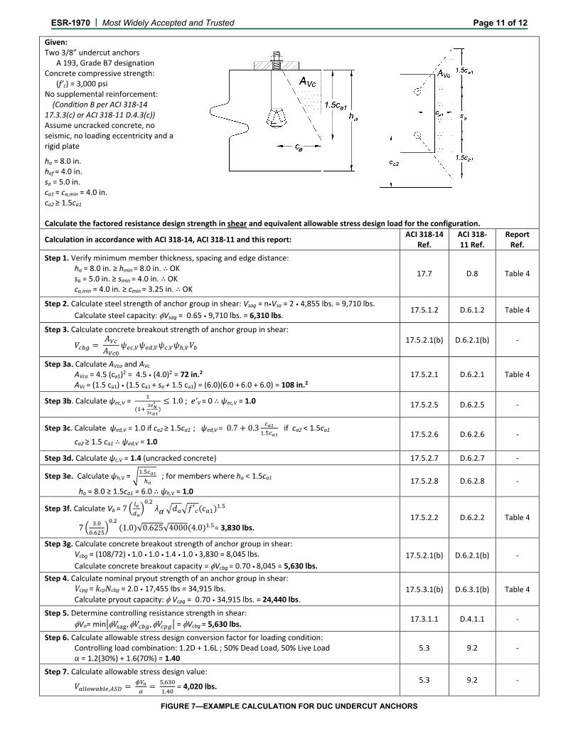
Given: Two 3/8” undercut anchors A 193, Grade B7 designation Concrete compressive strength: (f’c) = 3,000 psi No supplemental reinforcement: (Condition B per ACI 318‐14 17.3.3(c) or ACI 318‐11 D.4.3(c)) Assume uncracked concrete, no seismic, no loading eccentricity and a rigid plate
ha = 8.0 in. hef = 4.0 in. sa = 5.0 in. ca1 = ca,min = 4.0 in. ca2 ≥ 1.5ca1
Calculate the factored resistance design strength in shear and equivalent allowable stress design load for the configuration.
Calculation in accordance with ACI 318‐14, ACI 318‐11 and this report: ACI 318‐14
Ref. ACI 318‐11 Ref.
Report Ref.
Step 1. Verify minimum member thickness, spacing and edge distance: ha = 8.0 in. ≥ hmin = 8.0 in. ∴ OK sa = 5.0 in. ≥ smin = 4.0 in. ∴ OK ca,min = 4.0 in. ≥ cmin = 3.25 in. ∴ OK
17.7 D.8 Table 4
Step 2. Calculate steel strength of anchor group in shear: Vsag = n•Vsa = 2 • 4,855 lbs. = 9,710 lbs.
Calculate steel capacity: Vsag = 0.65 • 9,710 lbs. = 6,310 lbs. 17.5.1.2 D.6.1.2 Table 4
Step 3. Calculate concrete breakout strength of anchor group in shear:
, , , , 17.5.2.1(b) D.6.2.1(b) ‐
Step 3a. Calculate AVco and AVc AVco = 4.5 (ca1)2 = 4.5 • (4.0)2 = 72 in.2
AVc = (1.5 ca1) • (1.5 ca1 + sa + 1.5 ca1) = (6.0)(6.0 + 6.0 + 6.0) = 108 in.2 17.5.2.1 D.6.2.1 Table 4
Step 3b. Calculate ψec,V =
1.0 ; e’V = 0 ∴ ψec,V = 1.0 17.5.2.5 D.6.2.5 ‐
Step 3c. Calculate ψed,V = 1.0 if ca2 ≥ 1.5ca1 ; ψed,V = 0.7 0.3.
if ca2 < 1.5ca1
ca2 ≥ 1.5 ca1 ∴ ψed,V = 1.0 17.5.2.6 D.6.2.6 ‐
Step 3d. Calculate ψc,V = 1.4 (uncracked concrete) 17.5.2.7 D.6.2.7 ‐
Step 3e. Calculate ψh,V = . ; for members where ha < 1.5ca1
ha = 8.0 ≥ 1.5ca1 = 6.0 ∴ ψh,V = 1.0 17.5.2.8 D.6.2.8 ‐
Step 3f. Calculate Vb = 7.
′ .
7.
.
.1.0 √0.625√4000 4.0 . = 3,830 lbs.
17.5.2.2 D.6.2.2 Table 4
Step 3g. Calculate concrete breakout strength of anchor group in shear: Vcbg = (108/72) • 1.0 • 1.0 • 1.4 • 1.0 • 3,830 = 8,045 lbs.
Calculate concrete breakout capacity = Vcbg = 0.70 • 8,045 = 5,630 lbs. 17.5.2.1(b) D.6.2.1(b) ‐
Step 4. Calculate nominal pryout strength of an anchor group in shear: Vcpg=kcpNcbg= 2.0 • 17,455 lbs = 34,915 lbs.Calculate pryout capacity: Vcpg = 0.70 • 34,915 lbs. = 24,440 lbs.
17.5.3.1(b) D.6.3.1(b) Table 4
Step 5. Determine controlling resistance strength in shear:
Vn= min , , = Vcbg = 5,630 lbs. 17.3.1.1 D.4.1.1 ‐
Step 6. Calculate allowable stress design conversion factor for loading condition: Controlling load combination: 1.2D + 1.6L ; 50% Dead Load, 50% Live Load α = 1.2(30%) + 1.6(70%) = 1.40
5.3 9.2 ‐
Step 7. Calculate allowable stress design value:
, ,
. = 4,020 lbs.
5.3 9.2 ‐
FIGURE 7—EXAMPLE CALCULATION FOR DUC UNDERCUT ANCHORS
ICC-ES Evaluation Reports are not to be construed as representing aesthetics or any other attributes not specifically addressed, nor are they to be construed as an endorsement of the subject of the report or a recommendation for its use. There is no warranty by ICC Evaluation Service, LLC, express or implied, as to any finding or other matter in this report, or as to any product covered by the report.
Copyright © 2019 ICC Evaluation Service, LLC. All rights reserved. Page 12 of 12
ICC-ES Evaluation Report ESR-1970 LABC and LARC Supplement Issued December 2019
This report is subject to renewal June 2020.
www.icc-es.org | (800) 423-6587 | (562) 699-0543 A Subsidiary of the International Code Council ®
DIVISION: 03 00 00—CONCRETE Section: 03 16 00—Concrete Anchors DIVISION: 05 00 00—METALS Section: 05 05 19—Post-Installed Concrete Anchors REPORT HOLDER:
MiTek USA, INC. (FORMERLY USP STRUCTURAL CONNECTORS) EVALUATION SUBJECT:
DUC UNDERCUT ANCHORS 1.0 REPORT PURPOSE AND SCOPE
Purpose:
The purpose of this evaluation report supplement is to indicate that the MiTek USP DUC Undercut Anchors, described in ICC-ES master evaluation report ESR-1970, have also been evaluated for compliance with the codes noted below as adopted by Los Angeles Department of Building and Safety (LADBS).
Applicable code editions: 2017 City of Los Angeles Building Code (LABC)
2017 City of Los Angeles Residential Code (LARC)
2.0 CONCLUSIONS
The MiTek USP DUC Undercut Anchors, described in Sections 2.0 through 7.0 of the master evaluation report ESR-1970, comply with LABC Chapter 19, and LARC, and are subject to the conditions of use described in this report.
3.0 CONDITIONS OF USE The MiTek USP DUC Undercut Anchors described in this evaluation report must comply with all of the following conditions:
All applicable sections in the master evaluation report ESR-1970.
The design, installation, conditions of use and labeling of the anchors are in accordance with the 2015 International Building Code® (2015 IBC) provisions noted in the master evaluation report ESR-1970.
The design, installation and inspection are in accordance with additional requirements of LABC Chapters 16 and 17, as applicable.
Under the LARC, an engineered design in accordance with LARC Section R301.1.3 must be submitted.
The allowable and strength design values listed in the master evaluation report and tables are for the connection of the anchors to the concrete. The connection between the anchors and the connected members shall be checked for capacity (which may govern).
This supplement expires concurrently with the master report, reissued June 2018 and revised December 2019.