Embed Size (px)
Citation preview
NOTICE TO TENDERERS
Tender number: DBN/CAP (RTPC) 699
Tenders invited for: SUPPLY & DELIVERY OF NEW TRAIN RADIOS & SPARES FOR EXISTING RADIOS FOR METRORAIL KZN
With effect from 03 October 2016 and 07 October 2016 the tender document (CD) may be collected at:
Address: Metrorail Regional Office65 Masabalala Yengwa AvenueDurban Station
Office hours: Mondays to Fridays 08:00 to 15:30 (ONLY)
where CD’s can also be obtained on payment of an amount of R 1 000.00 per disc which is not refundable. No cash or cheques will be accepted at PRASA offices – (Bank Deposit or Electronic Payments - allow for 1-day delay). Clearly indicate the Tender Number on the Deposit Slip or EFT document as reference.
BANKING DETAILS:-
Metrorail KZN, Standard Bank, Windermere, Branch Code: 042726, Account No.: 050832948
Confirmation of EFT payment must be e-mailed to the Senior Buyer PRIOR to collecting the CD or attending the Briefing Session. Failing to do so will result in you not being granted access to the Briefing Session.
Tenderers must arrange own transport and parking. Tenderers failing to attend the compulsory tender briefing session will be disqualified. PRASA reserves the right to only allow tenderers in possession of a valid tender document at the
briefing. A maximum of two representatives per company will be allowed to attend the briefing. Tender documents (CD’s) are only available during the period stipulated above.
THE ONUS IS ON THE TENDERER TO PRINT THE DOCUMENT FROM THE CD DISC AND SUBMIT PRINTED TENDER DOCUMENTS WHEN SUBMITTING THEIR
TENDERS.
NB: IT IS MANDATORY REQUIREMENT FOR PROSPECTIVE SUPPLIERS TO BE REGISTERED ON THE CSD IN ALL REQUESTS FOR PROCUREMENT OF GOODS
AND / OR SERVICES.
BID ADVERTISEMENT FORM

SPECIFICATION
SUPPLY OF NEW TRAIN RADIOS AND SPARES FOR EXISTING RADIOS
A.1 PROJECT SCOPE
This specification covers the minimum requirements to be met for the supply of Trunk radio spares and train trunking radio system for Metrorail KZN region,
A.2 STANDARD SPECIFICATIONS AND INSTRUCTIONS OF METRORAIL KZN
The following specifications, instructions and documents shall form part of this document:
i) The schedule of quantitiesii) Technical radio specification
A.3 DURATION OF CONTRACT
Metrorail KZN requires that the supply be completed within the period of three years, which period shall include any statutory holiday falling within this period. The completion date will be determined by adding the period specified above to the date of written notification of acceptance of tender, or to such later date as may be specified in the advice of award. Lead-time has been built into the period specified.
A.4 PENALTIES FOR LATE COMPLETION
Should the Contractor fail to supply all required radios by the date stipulated in the contract or such extended period as may be allowed, he/she shall pay Metrorail KZN as penalties in terms of the Conventional Penalties Act of 1962, as amended, the sum of R500 (Five hundreds Rand) South African currency, per day of part thereof beyond the completion date.
A.5 SITE
The location for the delivery of trunk radio system shall be Infrastructure Telecoms Department (KZN PRASA Regional Office).
A.6 WARRANTY
The warranty period for all radios supplied and spares should be minimum of 12 months. The supplier should submit supporting documents to this effect.
A.7 PROGRAMMING OF RADIOS
Radio to be programmed as per Transnet allocated frequencies to Metrorail trunking network.Radios to be programmed by Transnet at the supplier’s cost.
BID ADVERTISEMENT FORM
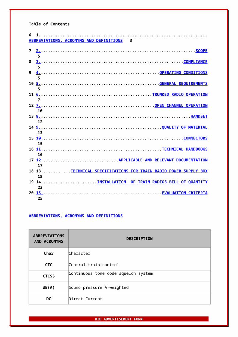
Table of Contents
6 1. .....................................................................................................................................................AB B REVI A TIONS, AC RO N YMS A ND DEF I N I TIONS 3
7 2. ......................................................................................................................................... SCOPE5
8 3. ..............................................................................................................................C O M PLIANCE 5
9 4. .........................................................................................................OPERATING CONDIT I ONS 5
10 5. ......................................................................................................GE N ERAL REQUIR EM ENTS 5
11 6. .................................................................................................TRU N KED RAD I O O P ERAT I ON 7
12 7. ...................................................................................................OP E N C HA NNEL OP E RATION 10
13 8. .................................................................................................................................... HA N DSET 12
14 9. ............................................................................................................QUALI T Y OF MAT E RI A L 13
15 10. ..........................................................................................................................CO N NEC T ORS 15
16 11. ......................................................................................................TECHN I C A L HAN D BOOKS 16
17 12. ...............................................................APPLI C A B LE AND R E LEVANT D OC U M E N T ATION 17
18 13..........................TECHNICAL SPECIFICATIONS FOR TRAIN RADIO POWER SUPPLY BOX18
19 14.......................................................INSTALLATION OF TRAIN RADIOS BILL OF QUANTITY23
20 15. ...........................................................................................................EVALUATION CRITERIA25
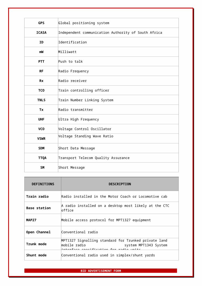
ABBREVIATIONS, ACRONYMS AND DEFINITIONS
ABBREVIATIONS AND ACRONYMS DESCRIPTION
Char Character
CTC Central train control
CTCSS Continuous tone code squelch system
dB(A) Sound pressure A-weighted
DC Direct Current
GPS Global positioning system
ICASA Independent communication Authority of South Africa
ID Identification
BID ADVERTISEMENT FORM

mW Milliwatt
PTT Push to talk
RF Radio Frequency
Rx Radio receiver
TCO Train controlling officer
TNLS Train Number Linking System
Tx Radio transmitter
UHF Ultra High Frequency
VCO Voltage Control Oscillator
VSWRVoltage Standing Wave Ratio
SDM Short Data Message
TTQA Transport Telecom Quality Assurance
SM Short Message
DEFINITIONS DESCRIPTION
Train radio Radio installed in the Motor Coach or Locomotive cab
Base station A radio installed on a desktop most likely at the CTC office
MAP27 Mobile access protocol for MPT1327 equipment
Open Channel Conventional radio
Trunk mode MPT1327 Signalling standard for Trunked private land mobile radio system MPT1343 System interface specification for radio units
Shunt mode Conventional radio used in simplex/shunt yards
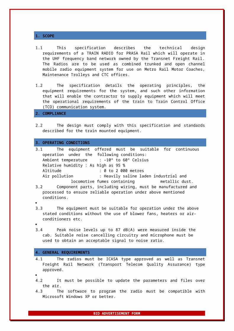
1. SCOPE
1.1 This specification describes the technical design requirements of a TRAIN RADIO for PRASA Rail which will operate in the UHF frequency band network owned by the Transnet
BID ADVERTISEMENT FORM
Freight Rail. The Radios are to be used as combined trunked and open channel mobile radio equipment system for use on Metro Rail Motor Coaches, Maintenance Trolleys and CTC offices.
1.2 The specification details the operating principles, the equipment requirements for the system, and such other information that will enable the contractor to supply equipment which will meet the operational requirements of the train to Train Control Office (TCO) communication system.
2. COMPLIANCE
2.2 The design must comply with this specification and standards described for the train mounted equipment.
3. OPERATING CONDITIONS3.1 The equipment offered must be suitable for continuous operation under the following
conditions:Ambient temperature : –10° to 60° Celsius Relative humidity : As high as 95 %Altitude : 0 to 2 000 metresAir pollution : Heavily saline laden industrial and locomotive fumes containing
metallic dust.3.2 Component parts, including wiring, must be manufactured and processed to ensure reliable
operation under above mentioned conditions.3.3 The equipment must be suitable for operation under the above stated conditions without the
use of blower fans, heaters or air-conditioners etc.3.4 Peak noise levels up to 87 dB(A) were measured inside the cab. Suitable noise cancelling
circuitry and microphone must be used to obtain an acceptable signal to noise ratio.
4. GENERAL REQUIREMENTS4.1 The radios must be ICASA type approved as well as Transnet Freight Rail Network
(Transport Telecom Quality Assurance) type approved.4.2 It must be possible to update the parameters and files over the air.4.3 The software to program the radio must be compatible with Microsoft Windows XP or better.4.4 The radios supplied must be programmed for open channel working as well as trunked
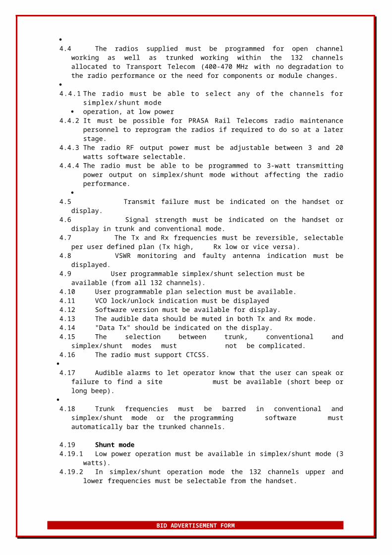
working within the 132 channels allocated to Transport Telecom (400-470 MHz with no degradation to the radio performance or the need for components or module changes.
4.4.1 The radio must be able to select any of the channels for simplex/shunt mode
operation, at low power4.4.2 It must be possible for PRASA Rail Telecoms radio maintenance personnel to reprogram
the radios if required to do so at a later stage.4.4.3 The radio RF output power must be adjustable between 3 and 20 watts software
selectable.4.4.4 The radio must be able to be programmed to 3-watt transmitting power output on
simplex/shunt mode without affecting the radio performance.
4.5 Transmit failure must be indicated on the handset or display.4.6 Signal strength must be indicated on the handset or display in trunk and conventional
mode.4.7 The Tx and Rx frequencies must be reversible, selectable per user defined plan (Tx high,
Rx low or vice versa). 4.8 VSWR monitoring and faulty antenna indication must be displayed.4.9 User programmable simplex/shunt selection must be available (from all 132 channels).4.10 User programmable plan selection must be available.4.11 VCO lock/unlock indication must be displayed4.12 Software version must be available for display.
BID ADVERTISEMENT FORM
4.13 The audible data should be muted in both Tx and Rx mode.4.14 "Data Tx" should be indicated on the display.4.15 The selection between trunk, conventional and simplex/shunt modes must
not be complicated.4.16 The radio must support CTCSS.
4.17 Audible alarms to let operator know that the user can speak or failure to find a site
must be available (short beep or long beep).4.18 Trunk frequencies must be barred in conventional and simplex/shunt mode
or the programming software must automatically bar the trunked channels.
4.19 Shunt mode4.19.1 Low power operation must be available in simplex/shunt mode (3 watts).4.19.2 In simplex/shunt operation mode the 132 channels upper and lower frequencies must
be selectable from the handset.4.19.3 Shunt on simplex mode must be selectable from the handset; any one of the
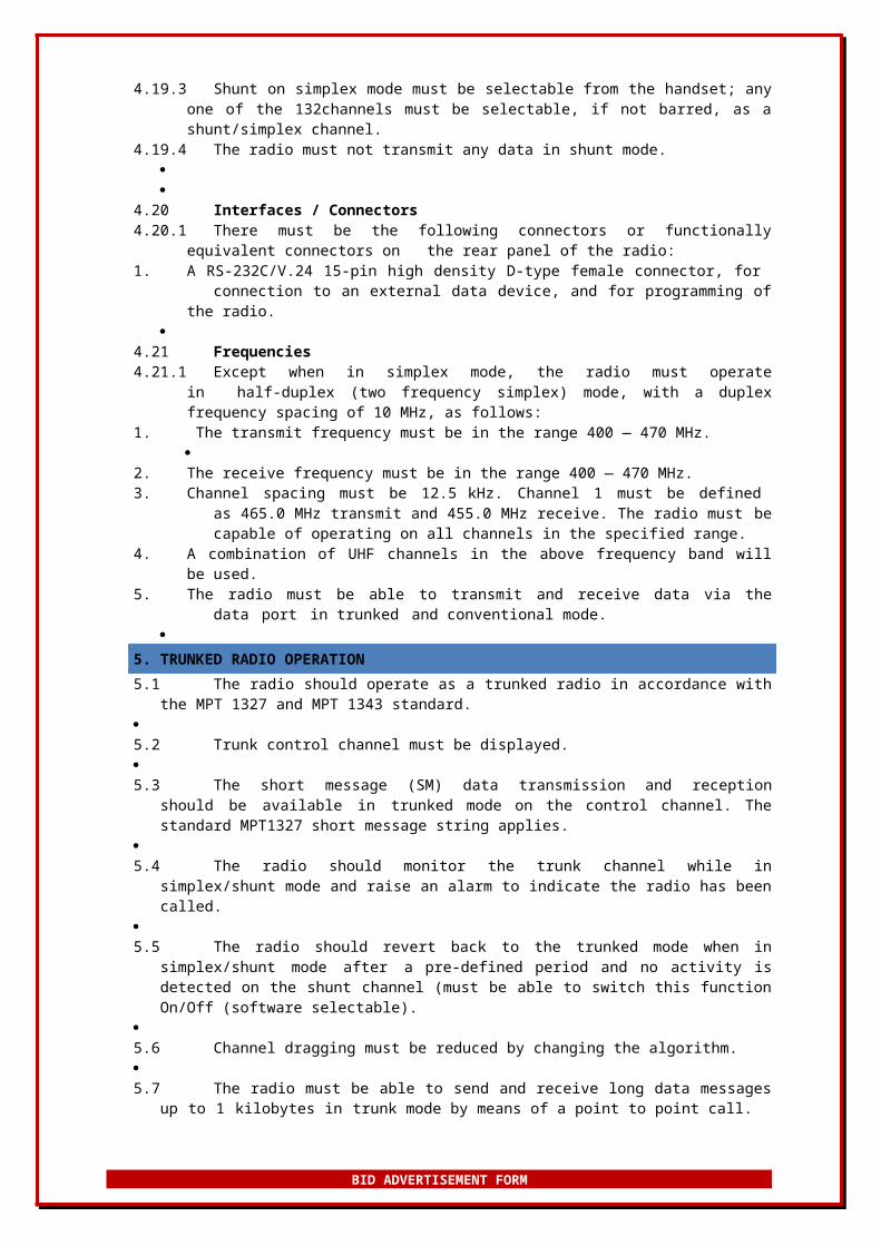
132channels must be selectable, if not barred, as a shunt/simplex channel.4.19.4 The radio must not transmit any data in shunt mode.
4.20 Interfaces / Connectors4.20.1 There must be the following connectors or functionally equivalent connectors on the
rear panel of the radio:1. A RS-232C/V.24 15-pin high density D-type female connector, for connection to an
external data device, and for programming of the radio.
4.21 Frequencies4.21.1 Except when in simplex mode, the radio must operate in half-duplex (two
frequency simplex) mode, with a duplex frequency spacing of 10 MHz, as follows:1. The transmit frequency must be in the range 400 — 470 MHz.
2. The receive frequency must be in the range 400 — 470 MHz.3. Channel spacing must be 12.5 kHz. Channel 1 must be defined as 465.0
MHz transmit and 455.0 MHz receive. The radio must be capable of operating on all channels in the specified range.
4. A combination of UHF channels in the above frequency band will be used.5. The radio must be able to transmit and receive data via the data port in
trunked and conventional mode.
5. TRUNKED RADIO OPERATION5.1 The radio should operate as a trunked radio in accordance with the MPT 1327 and MPT
1343 standard. 5.2 Trunk control channel must be displayed.5.3 The short message (SM) data transmission and reception should be available in trunked
mode on the control channel. The standard MPT1327 short message string applies.5.4 The radio should monitor the trunk channel while in simplex/shunt mode and raise an alarm
to indicate the radio has been called.5.5 The radio should revert back to the trunked mode when in simplex/shunt mode after
a pre-defined period and no activity is detected on the shunt channel (must be able to switch this function On/Off (software selectable).
5.6 Channel dragging must be reduced by changing the algorithm.5.7 The radio must be able to send and receive long data messages up to 1 kilobytes in trunk
mode by means of a point to point call.
BID ADVERTISEMENT FORM
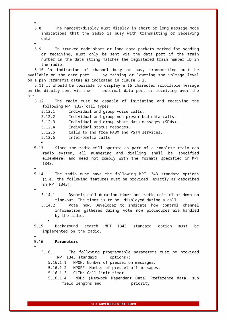
5.8 The handset/display must display in short or long message mode indications that the radio is busy with transmitting or receiving data
5.9 In trunked mode short or long data packets marked for sending or receiving, must only be
sent via the data port if the train number in the data string matches the registered train number ID in the radio.
5.10 An indication of channel busy or busy transmitting must be available on the data port by raising or lowering the voltage level on a pin (transmit data) as indicated in clause 6.2.
5.11 It should be possible to display a 16 character scrollable message on the display sent via the external data port or receiving over the air.
5.12 The radio must be capable of initiating and receiving the following MPT 1327 call types:5.12.1 Individual and group voice calls.5.12.2 Individual and group non-prescribed data calls.5.12.3 Individual and group short data messages (SDMs).5.12.4 Individual status messages.5.12.5 Calls to and from PABX and PSTN services.5.12.6 Inter-prefix calls.
5.13 Since the radio will operate as part of a complete train cab radio system, all numbering and dialling shall be specified elsewhere, and need not comply with the formats specified in MPT 1343.
5.14 The radio must have the following MPT 1343 standard options (i.e. the following features
must be provided, exactly as described in MPT 1343):
5.14.1 Dynamic call duration timer and radio unit clear down on time-out. The timer is to be displayed during a call.
5.14.2 Vote now. Developer to indicate how control channel information gathered during vote now procedures are handled by the radio.
5.15 Background search MPT 1343 standard option must be implemented on the radio.5.16 Parameters
5.16.1 The following programmable parameters must be provided (MPT 1343 standard options):
5.16.1.1 NPON: Number of pressel on messages.5.16.1.2 NPOFF: Number of pressel off messages.5.16.1.3 CLIM: Call limit timer.5.16.1.4 NDD: (Network Dependent Data) Preference data, sub field lengths and
priority5.16.1.5 Programmable flags (parameters) must be provided, to selectively bar
the Following types of calls:5.16.1.5.1 All group calls.5.16.1.5.2 Inter-fleet group calls.5.16.1.5.3 Inter-prefix calls.5.16.1.5.4 PABX calls.5.16.1.5.5 PSTN calls.5.16.1.5.6 High priority calls.5.16.1.5.7 Emergency calls.
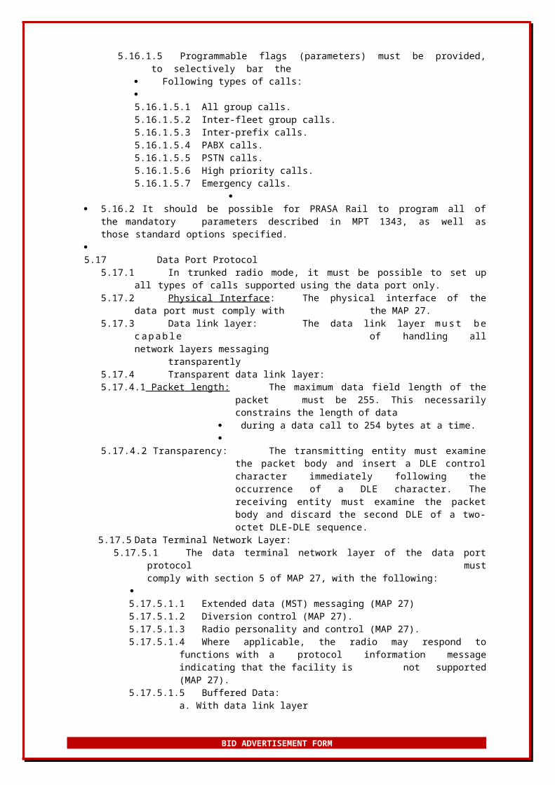
5.16.2 It should be possible for PRASA Rail to program all of the mandatory
parameters described in MPT 1343, as well as those standard options specified.5.17 Data Port Protocol
5.17.1 In trunked radio mode, it must be possible to set up all types of calls supported using the data port only.
5.17.2 Physical In t erface : The physical interface of the data port must comply with the MAP 27.
BID ADVERTISEMENT FORM
5.17.3 Data link layer: The data link layer m u s t b e c a p a b le of handling all network layers messaging transparently
5.17.4 Transparent data link layer:5.17.4.1 Packet leng t h : The maximum data field length of the packet must be 255.
This necessarily constrains the length of data during a data call to 254 bytes at a time.
5.17.4.2 Transparency: The transmitting entity must examine the packet body and insert a DLE control character immediately following the occurrence of a DLE character. The receiving entity must examine the packet body and discard the second DLE of a two-octet DLE-DLE sequence.
5.17.5 Data Terminal Network Layer:5.17.5.1 The data terminal network layer of the data port protocol
must comply with section 5 of MAP 27, with the following:
5.17.5.1.1 Extended data (MST) messaging (MAP 27)5.17.5.1.2 Diversion control (MAP 27).5.17.5.1.3 Radio personality and control (MAP 27).5.17.5.1.4 Where applicable, the radio may respond to functions with a protocol
information message indicating that the facility is not supported (MAP 27).
5.17.5.1.5 Buffered Data:a. With data link layerb. Without data link layer
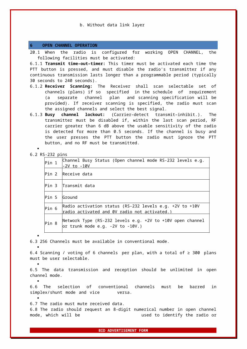
6 OPEN CHANNEL OPERATION20.1 When the radio is configured for working OPEN CHANNEL, the following facilities must be
activated:6.1.1 Transmit time–out–timer: This timer must be activated each time the PTT button is pressed, and must disable the radio's transmitter if any continuous transmission lasts longer than a programmable period (typically 30 seconds to 240 seconds).6.1.2 Receiver Scanning: The Receiver shall scan selectable set of channels (plans) if so
specified in the schedule of requirement (a separate channel plan and scanning specification will be provided). If receiver scanning is specified, the radio must scan the assigned channels and select the best signal.
6.1.3 Busy channel lockout: (Carrier–detect transmit–inhibit.). The transmitter must be disabled if, within the last scan period, RF carrier greater than 6 dB above the usable sensitivity of the radio is detected for more than 0.5 seconds. If the channel is busy and the user presses the PTT button the radio must ignore the PTT button, and no RF must be transmitted.
6.2 RS-232 pins
Pin 1 Channel Busy Status (Open channel mode RS-232 levels e.g. -2V to -10Vnot busy and channel busy +2V to +10V.)
Pin 2 Receive data
Pin 3 Transmit data
Pin 5 Ground
Pin 6 Radio activation status (RS-232 levels e.g. +2V to +10V radio activated and 0V radio not activated.)
Pin 8 Network Type (RS-232 levels e.g. +2V to +10V open channel or trunk mode e.g. -2V to -10V.)
BID ADVERTISEMENT FORM
6.3 256 Channels must be available in conventional mode.
6.4 Scanning / voting of 6 channels per plan, with a total of ≥ 300 plans must be user selectable.
6.5 The data transmission and reception should be unlimited in open channel mode.
6.6 The selection of conventional channels must be barred in simplex/shunt mode and vice versa.
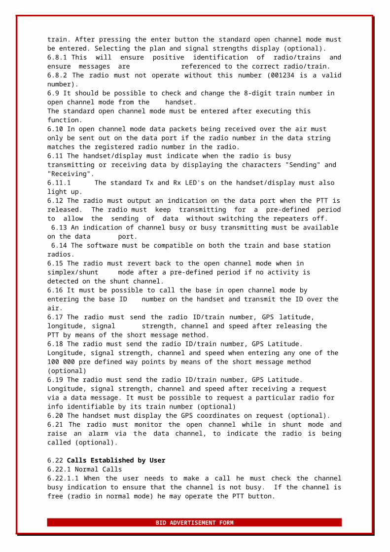
6.7 The radio must mute received data.6.8 The radio should request an 8-digit numerical number in open channel mode, which will be used to identify the radio or train. After pressing the enter button the standard open channel mode must be entered. Selecting the plan and signal strengths display (optional).6.8.1 This will ensure positive identification of radio/trains and ensure messages are referenced to the correct radio/train.6.8.2 The radio must not operate without this number (001234 is a valid number).6.9 It should be possible to check and change the 8-digit train number in open channel mode from the handset.The standard open channel mode must be entered after executing this function.6.10 In open channel mode data packets being received over the air must only be sent out on the data port if the radio number in the data string matches the registered radio number in the radio.6.11 The handset/display must indicate when the radio is busy transmitting or receiving data by displaying the characters "Sending" and "Receiving".6.11.1 The standard Tx and Rx LED's on the handset/display must also light up.6.12 The radio must output an indication on the data port when the PTT is released. The radio must keep transmitting for a pre-defined period to allow the sending of data without switching the repeaters off. 6.13 An indication of channel busy or busy transmitting must be available on the data port. 6.14 The software must be compatible on both the train and base station radios.6.15 The radio must revert back to the open channel mode when in simplex/shunt mode after a pre-defined period if no activity is detected on the shunt channel.6.16 It must be possible to call the base in open channel mode by entering the base ID
number on the handset and transmit the ID over the air.6.17 The radio must send the radio ID/train number, GPS latitude, longitude, signal strength, channel and speed after releasing the PTT by means of the short message method.6.18 The radio must send the radio ID/train number, GPS Latitude. Longitude, signal strength, channel and speed when entering any one of the 100 000 pre defined way points by means of the short message method (optional)6.19 The radio must send the radio ID/train number, GPS Latitude. Longitude, signal strength, channel and speed after receiving a request via a data message. It must be possible to request a particular radio for info identifiable by its train number (optional)6.20 The handset must display the GPS coordinates on request (optional).6.21 The radio must monitor the open channel while in shunt mode and raise an alarm via the data channel, to indicate the radio is being called (optional).
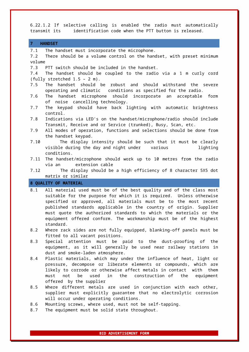
6.22 Calls Established by User6.22.1 Normal Calls6.22.1.1 When the user needs to make a call he must check the channel busy indication to ensure that the channel is not busy. If the channel is free (radio in normal mode) he may operate the PTT button.6.22.1.2 If selective calling is enabled the radio must automatically transmit its identification code when the PTT button is released.
7 HANDSET7.1 The handset must incorporate the microphone.7.2 There should be a volume control on the handset, with preset minimum volume7.3 PTT switch should be included in the handset.7.4 The handset should be coupled to the radio via a 1 m curly cord (fully stretched 1.5 – 2 m).7.5 The handset should be robust and should withstand the severe operating and climatic
conditions as specified for the radio.
BID ADVERTISEMENT FORM
7.6 The handset microphone should incorporate an acceptable form of noise cancelling technology.
7.7 The keypad should have back lighting with automatic brightness control.7.8 Indications via LED's on the handset/microphone/radio should include Transmit, Receive and
or Service (trunked), Busy, Scan, etc.7.9 All modes of operation, functions and selections should be done from the handset keypad.7.10 The display intensity should be such that it must be clearly visible during the day and night
under various lighting conditions.7.11 The handset/microphone should work up to 10 metres from the radio via an extension
cable7.12 The display should be a high efficiency of 8 character 5X5 dot matrix or similar8 QUALITY OF MATERIAL8.1 All material used must be of the best quality and of the class most suitable for the purpose
for which it is required. Unless otherwise specified or approved, all materials must be to the most recent published standards applicable in the country of origin. Supplier must quote the authorized standards to which the materials or the equipment offered conform. The workmanship must be of the highest standard.
8.2 Where rack sides are not fully equipped, blanking-off panels must be fitted to all vacant positions.
8.3 Special attention must be paid to the dust-proofing of the equipment, as it will generally be used near railway stations in dust and smoke-laden atmosphere.
8.4 Plastic materials, which may under the influence of heat, light or pressure, decompose or liberate elements or compounds, which are likely to corrode or otherwise affect metals in contact with them must not be used in the construction of the equipment offered by the supplier
8.5 Where different metals are used in conjunction with each other, supplier must explicitly guarantee that no electrolytic corrosion will occur under operating conditions.
8.6 Mounting screws, where used, must not be self-tapping.8.7 The equipment must be solid state throughout.8.8 Solid-state devices are to be so constructed that they may be easily tested for correct
functioning without having to disturb wiring.8.9 Printed-wiring boards must be properly washed and, if necessary, neutralized after the
etching process so that no hygroscopic crystals remain in the board or printed wiring.8.10 Printed wiring boards must be guaranteed not to promote or permit the growth of fungi under
any conditions.8.11 Printed wiring boards must preferably be fitted with robust plugs and sockets or another
approved manner of connecting the boards reliably to the wiring. Edge connectors may be used provided that:
8.11.1 A suitable tolerance for the correct fitting of the board between guides and the wiring socket can be guaranteed.
8.11.2 Sufficient contact area is provided to guarantee reliable contact.8.11.3 In the final protective coating of the boards, no varnish or other protective materials is
permitted to cover the contacts.8.11.4 Sufficient contact pressure is provided to ensure contact but not to remove precious metal
from the contact. 8.11.5 After 500 insertions and withdrawals, there must be no noticeable deterioration of the
contacts of either the board or socket.
8.12 All printed wiring board's sockets; plugs or edge connectors must be gold plated or better.8.13 Heavy components must not be mounted on printed wiring boards unless it can
be guaranteed that the board will stand up to severe handling without fracturing with the components so mounted.
8.14 Solid-state boards must be provided on a plug-in or other approved basis so that they can, when necessary, be readily removed for repairs. Supplier must recommend the quantities of spare units to be kept on hand.
8.15 No unmarked and/or untested components may be used.8.16 All components used must be types, which can be readily obtained from local suppliers.8.17 The number of component types must be kept to a minimum consistent with good design of
the equipment.8.18 All components must be suitably rated for the function they have to perform without
interference to neighbouring material.
BID ADVERTISEMENT FORM
8.19 Resistors and resistive components must not rise in temperature so that mounting boards or marking thereon are burnt or discoloured.
8.20 Electrolytic capacitors must not be used in any critical timing or frequency control circuits.8.21 Fuses must be rated to give adequate protection to the circuits served while not rupturing
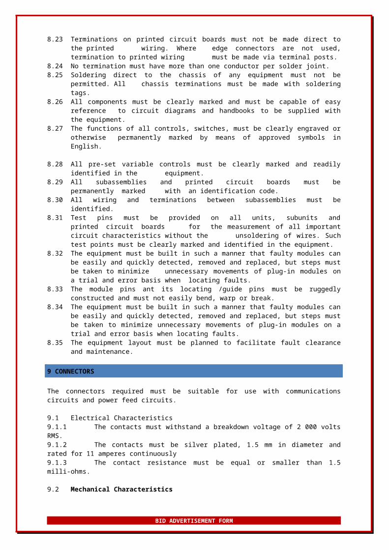
prematurely.8.22 Illuminated status indicators must be light emitting diodes (LED) types.8.23 Terminations on printed circuit boards must not be made direct to the printed wiring.
Where edge connectors are not used, termination to printed wiring must be made via terminal posts.
8.24 No termination must have more than one conductor per solder joint.8.25 Soldering direct to the chassis of any equipment must not be permitted. All chassis
terminations must be made with soldering tags.8.26 All components must be clearly marked and must be capable of easy reference to circuit
diagrams and handbooks to be supplied with the equipment.8.27 The functions of all controls, switches, must be clearly engraved or otherwise
permanently marked by means of approved symbols in English.
8.28 All pre-set variable controls must be clearly marked and readily identified in the equipment.8.29 All subassemblies and printed circuit boards must be permanently marked with an
identification code.8.30 All wiring and terminations between subassemblies must be identified.8.31 Test pins must be provided on all units, subunits and printed circuit boards for
the measurement of all important circuit characteristics without the unsoldering of wires. Such test points must be clearly marked and identified in the equipment.
8.32 The equipment must be built in such a manner that faulty modules can be easily and quickly detected, removed and replaced, but steps must be taken to minimize unnecessary movements of plug-in modules on a trial and error basis when locating faults.
8.33 The module pins ant its locating /guide pins must be ruggedly constructed and must not easily bend, warp or break.
8.34 The equipment must be built in such a manner that faulty modules can be easily and quickly detected, removed and replaced, but steps must be taken to minimize unnecessary movements of plug-in modules on a trial and error basis when locating faults.
8.35 The equipment layout must be planned to facilitate fault clearance and maintenance.
9 CONNECTORS
The connectors required must be suitable for use with communications circuits and power feed circuits.
9.1 Electrical Characteristics9.1.1 The contacts must withstand a breakdown voltage of 2 000 volts RMS.9.1.2 The contacts must be silver plated, 1.5 mm in diameter and rated for 11 amperes continuously9.1.3 The contact resistance must be equal or smaller than 1.5 milli-ohms.
9.2 Mechanical Characteristics9.2.1 The insulator must be a neoprene elastomeric material.9.2.2 The contacts must be silver plated and must be suitable for at least 500 mating/un-
mating operations.
9.3 Climatic Conditions9.3.1 The connector must operate from -40 °C to +85 °C.9.3.2 The connector must seal as per NFC.20010-IP61.9.3.3 The connector must be spray resistant as per NFC.20611.
10 TECHNICAL HANDBOOKS10.1 Technical handbooks must be clearly printed in English. Photostat copies will not be
acceptable.10.2 Each set of handbooks must include the following:10.2.1 Operating instructions.
BID ADVERTISEMENT FORM
10.2.2 Complete maintenance instructions.10.2.3 Complete and detailed alignment procedures.10.2.4 A detailed technical description of the equipment.10.2.5 Complete circuit diagrams, drawings and photographs of the equipment. The photographs
and drawing must clearly indicate component/module location on printed circuit boards etc. All component numbers must be clearly shown.
10.2.6 A list of parts giving the values of all components, i.e.10.2.6.1 Resistors,10.2.6.2 Capacitors,10.2.7 Integrated circuit numbers etc., for each schematic drawing.10.2.8 Detailed printed circuit board wiring diagrams of all layers showing component numbers and
positions must be provided. Panel and or unit wiring diagrams must also be provided.10.2.9 Voltage level, current values, test points etc., should be clearly indicated on all circuit
diagrams.10.2.10 Voltage levels, current values, test points etc., must be clearly indicated on all circuit
diagrams.10.2.11 complete circuit diagrams of individual modules must be included.10.2.12 A block schematic of the complete system, indicating all test points as well as the
level readings which should be obtained at these points.10.2.13 All indicated levels in the equipment and in the instruction books must be given in
power levels (0 dB = 1 mW into 600 ohms).10.2.14 All symbols and notations used on drawings and circuit diagrams must preferably
comply with the requirements laid down in BS 3939. Where symbols and notations do not comply with these requirements each drawing must be accompanied by a legend clearly detailing BS 3939 equivalents.
10.2.15 PRASA Rail reserves the right to reproduce in whole or in part, by any means whatsoever, any technical handbook or instruction manual supplied by the successful contractor. Any such reproductions will be for the sole use of PRASA Rail.
10.2.16 To enable the personnel of PRASA Rail to become acquainted with the circuitry and design details of the equipment ordered, the successful contractor must deliver one complete set of handbooks to each centre mentioned in the Schedule of Requirements, delivery to be effected at least one month prior to the commencement of the delivery of the equipment.
10.2.17 Programming software and service manuals to be supplied on a CD-ROM.
11APPLICABLE AND RELEVANT DOCUMENTATION
The equipment must comply with the latest issue of the following specifications:APPLICABLE
DOCUMENT NO. DESCRIPTION LOCATION
BBD8635 Technical Specification and Methods of Measurement for Angle Modulated Radio Equipment TFR
ISO 9000 Quality Management Systems EXTERNAL
British Department of Trade and Industry Specification:
MPT 1317 Code of Practice for Transmission of Digital Information over Land Mobile Radio Systems External
MPT 1327 A signalling Standard for Trunked Private Mobile Radio Systems External
MPT 1343 System Interface Specification for Radio Units to be used with Commercial Trunked Networks External
RELEVANT
BID ADVERTISEMENT FORM
The following additional specifications are referred to:
DOCUMENT NO. DESCRIPTION LOCATION
MAP 27 Mobile Access Protocol for MPT 1327 equipment (UADG) (Version 1.5, January 1998) External
ITU V.24 RS 232 External
ANNEXURE A
TECHNICAL SPECIFICATIONS FOR TRAIN RADIO POWER SUPPLY BOX Description Block Diagram
Fig 1
Physical Box: Newly improvement, cost effective, robust, fireproof, suitable for railway Train Bourne with unique locking mechanism for vandal proofing.
BID ADVERTISEMENT FORM
110 VDC SOURCE from Train Supplier
Box DC PLUG
DC-to-DC Converter
Battery Charging
110 VDC Surge Suppression Unit
All exposed equipment from the box must be vandal proofed. The Box must have its serial/part number engraved for installation and maintenance purposes.
Fig 2
Power INPUT Socket: An industrial DC plug/socket must be used suitable to Railway environment. A power indication LED shall be installed and visible for maintenance purposes.
Power protection circuit: The 110V input voltage may have high, low and spike voltages. An industrial surge suppression unit suitable for Railway cab on-board is needed, the board must be reliable. Below is the current used board to be used as reference.
S489 - Input Surge Suppression For 110V DC Inputs Replacement for S424 Fuse protection in positive &
negative lines
Fig 3
DC-DC Isolating converter: The use of industrial DC-to-DC isolation converted is required, the unit shall be reliable and suitable for Railway environment. Below is the current unit used as a reference. S008A DC-DC Convertor
BID ADVERTISEMENT FORM
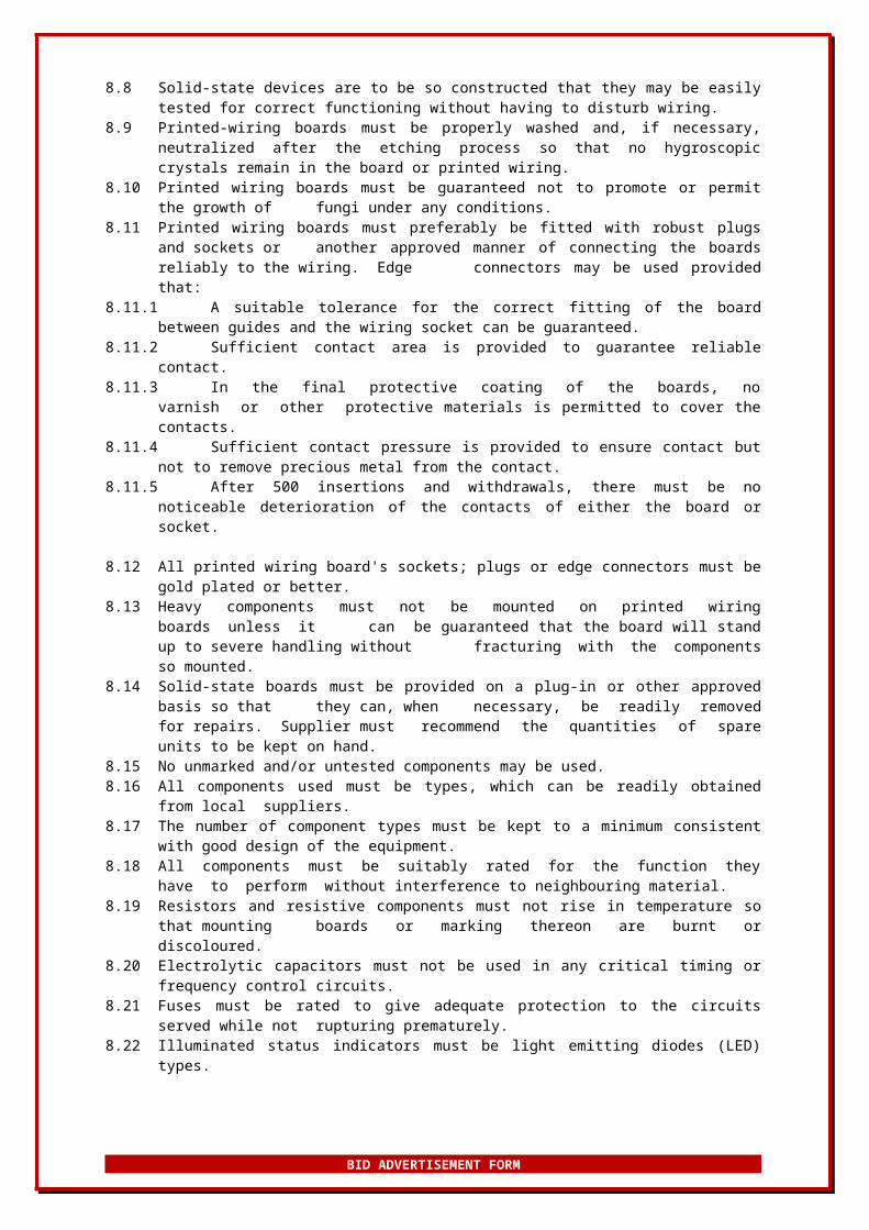
Fig 4Low Voltage Disconnect: The board is used for protection of the battery and regulates the
charging of the battery. The unit also disconnects the power from the battery to the Radio when a low voltage is detected from the Battery. Protection means in this regards is required, a redesigned means reliable and improved with cost effectiveness suitable for Railway environment shall be delivered as a solution for PRASA Rail. Below is the current unit being used as a reference:
S464 - Low Voltage Disconnect BoardFor use with 12V 7A/Hr Lead-acid battery.Uses N Channel FET to Switch Negative Line.Trip Voltage 10.5VRestore Voltage 12.5V
Fig 5External Speaker: Industrial pre-amped speaker with great audio quality and reliability
shall be installed in the Box. The volume of the speaker must be not be controllable from the box, but through the Radio Handset.
Antenna connector: A panel mount N-type female connector shall be mounted on the inner box. The cable on the inside shall be fitted with an appropriate connector that will fit onto the radio antenna connector. The cable shall be suitable to be used in the Railway environment.
Battery: Ni-Cd rail batteries manufactured in accordance with high quality standard meeting all international standards such as the IEC 60623, ISO 9001 and ISO 14001.The battery must have:
o resistance against electrical and mechanical stresso no risk of terminal decompose or sudden death due to
material constructiono extremely long lifetimeo operational temperature range between - 40°C and + 50°Co extremely long storage life – for several years in a discharged
state under correct conditions o maintenance freeo 7 Ah capacity or better (The expected power support must
last 6 hours on load)Below is the current battery used as a reference:
Fig 6
BID ADVERTISEMENT FORM
Speaker: An industrialized external speaker suitable for Railway use shall be used and mounted on the outer box. The speaker shall qualify audio quality designed with the audio output of the supplied radio for optimized audio quality output.
Fig 7
END OF SPECIFICATION
BID ADVERTISEMENT FORM