Embed Size (px)
Citation preview

ETSI TR 102 513 V1.1.1 (2006-12)
Technical Report
Terrestrial Trunked Radio (TETRA);Feasibility Study into the Implications of Operating
Public Safety Sector (PSS) TEDS using the proposed"Tuning Range" concept in the 410 MHz to 430 MHz and
450 MHz to 470 MHz frequency bands
ETSI
ETSI TR 102 513 V1.1.1 (2006-12) 2
Reference DTR/TETRA-000175
Keywords TETRA, radio
ETSI
650 Route des Lucioles F-06921 Sophia Antipolis Cedex - FRANCE
Tel.: +33 4 92 94 42 00 Fax: +33 4 93 65 47 16
Siret N° 348 623 562 00017 - NAF 742 C
Association à but non lucratif enregistrée à la Sous-Préfecture de Grasse (06) N° 7803/88
Important notice
Individual copies of the present document can be downloaded from: http://www.etsi.org
The present document may be made available in more than one electronic version or in print. In any case of existing or perceived difference in contents between such versions, the reference version is the Portable Document Format (PDF).
In case of dispute, the reference shall be the printing on ETSI printers of the PDF version kept on a specific network drive within ETSI Secretariat.
Users of the present document should be aware that the document may be subject to revision or change of status. Information on the current status of this and other ETSI documents is available at
http://portal.etsi.org/tb/status/status.asp
If you find errors in the present document, please send your comment to one of the following services: http://portal.etsi.org/chaircor/ETSI_support.asp
Copyright Notification
No part may be reproduced except as authorized by written permission. The copyright and the foregoing restriction extend to reproduction in all media.
© European Telecommunications Standards Institute 2006.
All rights reserved.
DECTTM, PLUGTESTSTM and UMTSTM are Trade Marks of ETSI registered for the benefit of its Members. TIPHONTM and the TIPHON logo are Trade Marks currently being registered by ETSI for the benefit of its Members. 3GPPTM is a Trade Mark of ETSI registered for the benefit of its Members and of the 3GPP Organizational Partners.

ETSI
ETSI TR 102 513 V1.1.1 (2006-12) 3
Contents
Intellectual Property Rights ................................................................................................................................5
Foreword.............................................................................................................................................................5
Introduction ........................................................................................................................................................5
1 Scope ........................................................................................................................................................6
2 References ................................................................................................................................................6
3 Abbreviations ...........................................................................................................................................6
4 Feasibility study introduction and summary ............................................................................................7
5 Frequency spectrum considerations .........................................................................................................7 5.1 General ...............................................................................................................................................................7 5.2 TETRA base station frequency spectrum considerations ...................................................................................8 5.3 TETRA radio terminal radio spectrum considerations .......................................................................................8
6 Implications on use of wideband mobile stations covering 380 MHz to 470 MHz .................................9 6.1 General ...............................................................................................................................................................9 6.2 RF PA linearity...................................................................................................................................................9 6.3 RF Wideband Noise ...........................................................................................................................................9 6.4 Switching time between TETRA V+D and TEDS channels ............................................................................10 6.5 Conclusions ......................................................................................................................................................10 6.6 Recommendations ............................................................................................................................................10
7 Mobile station antenna implications.......................................................................................................10 7.1 General .............................................................................................................................................................10 7.2 Conclusions ......................................................................................................................................................11
8 Base station antenna implications ..........................................................................................................11 8.1 General .............................................................................................................................................................11 8.2 Conclusions ......................................................................................................................................................12
9 Implications of transmitter combining and receiver splitting systems at TETRA base station sites .....12 9.1 General .............................................................................................................................................................12 9.2 TETRA V+D with a single 50 kHz TEDS channel ..........................................................................................13 9.3 Conclusions ......................................................................................................................................................15
10 Security implications of public safety sharing frequency bands used by non-public safety users.........16
11 TEDS channel bandwidth assignment implications ...............................................................................16 11.1 General .............................................................................................................................................................16 11.2 Conclusion........................................................................................................................................................17
12 Spectrum efficiency implications of TETRA V+D and TEDS in the same frequency band versus TETRA V+D and TEDS in separate frequency bands...........................................................................17
12.1 General .............................................................................................................................................................17 12.2 Guard band requirements .................................................................................................................................18 12.3 Radio frequency planning constraints ..............................................................................................................18 12.4 Conclusion........................................................................................................................................................20
13 Propagation and coverage implications of the control channels and TEDS channels being in different frequency bands.......................................................................................................................20
13.1 General .............................................................................................................................................................20 13.2 Path loss differences.........................................................................................................................................20 13.3 Wavelength differences ....................................................................................................................................21 13.4 Conclusion........................................................................................................................................................21
14. Implications of two antenna system working at base station sites .........................................................21 14.1 General .............................................................................................................................................................21 14.2 Additional cost .................................................................................................................................................21

ETSI
ETSI TR 102 513 V1.1.1 (2006-12) 4
14.3 Additional space, weight and wind loading on radio masts .............................................................................21 14.4 Difference in RF coverage characteristics........................................................................................................22 14.5 Environmental impact ......................................................................................................................................22 14.6 Conclusions ......................................................................................................................................................22
15. Alternative solutions...............................................................................................................................22 15.1 General .............................................................................................................................................................22 15.1.1 Split band: solution 1 ..................................................................................................................................22 15.1.2 Single band: solution 2 ...............................................................................................................................23 15.2 Conclusions ......................................................................................................................................................23
16. Overall conclusions ................................................................................................................................23
17. Recommendations ..................................................................................................................................24
Annex A: Antenna performance specifications ...................................................................................25
A.1 General ...................................................................................................................................................25
A.2 VSWR ....................................................................................................................................................25
A.3 Conclusions ............................................................................................................................................26
Annex B: Bibliography..........................................................................................................................27
History ..............................................................................................................................................................28

ETSI
ETSI TR 102 513 V1.1.1 (2006-12) 5
Intellectual Property Rights IPRs essential or potentially essential to the present document may have been declared to ETSI. The information pertaining to these essential IPRs, if any, is publicly available for ETSI members and non-members, and can be found in ETSI SR 000 314: "Intellectual Property Rights (IPRs); Essential, or potentially Essential, IPRs notified to ETSI in respect of ETSI standards", which is available from the ETSI Secretariat. Latest updates are available on the ETSI Web server (http://webapp.etsi.org/IPR/home.asp).
Pursuant to the ETSI IPR Policy, no investigation, including IPR searches, has been carried out by ETSI. No guarantee can be given as to the existence of other IPRs not referenced in ETSI SR 000 314 (or the updates on the ETSI Web server) which are, or may be, or may become, essential to the present document.
Foreword This Technical Report (TR) has been produced by ETSI Technical Committee Terrestrial Trunked Radio (TETRA).
Introduction The present document looks at the feasibility of operating a Public Safety Sector (PSS) TETRA V+D network in the 380 MHz to 385 MHz/390 MHz to 395 MHz band with TETRA Enhanced Data Service (TEDS) operating in either the 410 MHz to 430 MHz band or the 450 MHz to 470 MHz band.
The need for this feasibility study occurred as a result of a Liaison Statement (LS) document FM38(2006), FM38 (2006)25 [1] for ETSI TC TETRA to consider the feasibility of a "tuning range" concept to accommodate PSS TEDS in the 410 MHz to 430 MHz band or the 450 MHz to 470 MHz band if frequency spectrum could not be made available in the preferred 385 MHz to 390 MHz/395 MHz to 399,9 MHz band.
NOTE: Insufficient spectrum is available in the 380 MHz to 385 MHz/390 MHz to 395 MHz band to support TEDS.
The "tuning range" concept was also proposed because no common blocks of spectrum could be identified in the 410 MHz to 430 MHz and 450 MHz to 470 MHz bands across the CEPT region.

ETSI
ETSI TR 102 513 V1.1.1 (2006-12) 6
1 Scope The present document considers possible implications covering the following areas:
• Frequency Spectrum Considerations.
• Implications on use of wideband terminals covering 380 MHz to 470 MHz.
• Radio terminal antenna implications.
• Base station antenna implications.
• Implications of transmitter combining and receiver splitting systems at TETRA base station sites.
• Security implications of Public Safety sharing frequency bands used by non-public safety users.
• TEDS channel bandwidth assignment implications.
• Spectrum efficiency implications of TETRA V+D and TEDS in the same band versus TETRA V+D and TEDS in separate bands.
• Propagation and coverage implications of the control channels and TEDS channels being in different frequency bands.
• Implications of Two Antenna System Working at Base Station Sites.
• Alternative Solutions.
2 References For the purposes of this Technical Report (TR) the following references apply:
NOTE: While any hyperlinks included in this clause were valid at the time of publication ETSI cannot guarantee their long term validity.
[1] FM38(2006)25: "Liaison Statement (LS) from FM PT38 to ETSI ERM-RM regarding information to be contained in an SRDoc".
3 Abbreviations For the purposes of the present document, the following abbreviations apply:
ACP Adjacent Channel Power C/I Carrier to Interference CDMA Code Division Multiple Access CEPT Conference Européenne des Administrations des Postes et des Télécommunications DC Direct Current DMO Direct Mode Operation ECC Electronic Communications Committee (of the CEPT) FDMA Frequency Division Multiple Access FM PT38 WG FM Project Team on PMR FM Frequency Modulation FSL Free Space Loss GoS Grade of Service MS Mobile Station PA Power Amplifier PMR Private Mobile Radio PPDR Public Protection and Disaster Relief PSS Public Safety Sector

ETSI
ETSI TR 102 513 V1.1.1 (2006-12) 7
QAM Quadrature Amplitude Modulation RF Radio Frequency Rx Receive(r) TEDS TETRA Enhanced Data Service TETRA Terrestrial Trunked RAdio Tx Transmit(ter) V+D Voice plus Data VCO Voltage Controlled Oscillator VSWR Voltage Standing Wave Ratio W Watts WGFM Working Group Frequency Management
4 Feasibility study introduction and summary The present document looks at the feasibility of using a "tuning range" concept of operating a Public Safety Sector (PSS) TETRA Enhanced Data Service (TEDS) in either the 410 MHz to 430 MHz band or the 450 MHz to 470 MHz band if frequency spectrum could not be made available in the preferred 385,0 MHz to 390,0 MHz/395,0 MHz to 399,9 MHz band.
In carrying out this feasibility study and analysing its findings a number of conclusions and recommendations have been made, the most significant recommendation being that CEPT ECC WGFM should continue exploring the possibility of assigning adequate frequency spectrum from the 385,0 MHz to 390,0 MHz/395,0 MHz to 400,0 MHz band to accommodate TEDS, as it has been concluded that the single frequency band solution is the most cost effective and practical solution that meets the needs of existing PSS users of TETRA V+D wishing to upgrade to TEDS.
The main factor that resulted in this recommendation was that the most common base station antenna (high gain collinear) used in TETRA by PPS organizations was limited to a RF bandwidth of 32 MHz, which was insufficient to accommodate TETRA V+D and TEDS in the 410 MHz to 430 MHz band or the 450 MHz to 470 MHz band operating on an antenna system comprising one transmit (Tx) antenna and one receive (Rx) antenna (1 x Tx and 1 x Rx).
As a consequence both existing TETRA networks and new TETRA networks with TEDS would require two antenna systems (2 x Tx and 2 x Rx) at each base station site, which for cost and practical reasons is not considered acceptable.
However, this feasibility study did identify the possibility of using a split band operation solution, which is considered acceptable for new TETRA users but not suitable for existing PSS users of TETRA wishing to upgrade to TEDS. To remove the need for two independent antenna systems at each TETRA base station site a decision is made during the network planning phase to assign chosen base stations sites to operate in either the 380 MHz to 385/390 MHz to 395 MHz band or the 410 MHz to 430 MHz band
NOTE: Assumes radio terminals can operate across 380 MHz to 430 MHz with acceptable degradation but not 380 MHz to 470 MHz.
This solution means that each base station site will only need one antenna system (1 x Tx and 1 x Rx). However, this solution does create a number of problems, details of which are provided in clause 15.
5 Frequency spectrum considerations
5.1 General As mentioned in the Introduction, the "Tuning Range" concept was also proposed because no common blocks of spectrum could be identified in the 410 MHz to 430 MHz and 450 MHz to 470 MHz bands across the CEPT region. This means that TEDS if deployed in these bands could be allocated frequency spectrum anywhere within these bands.
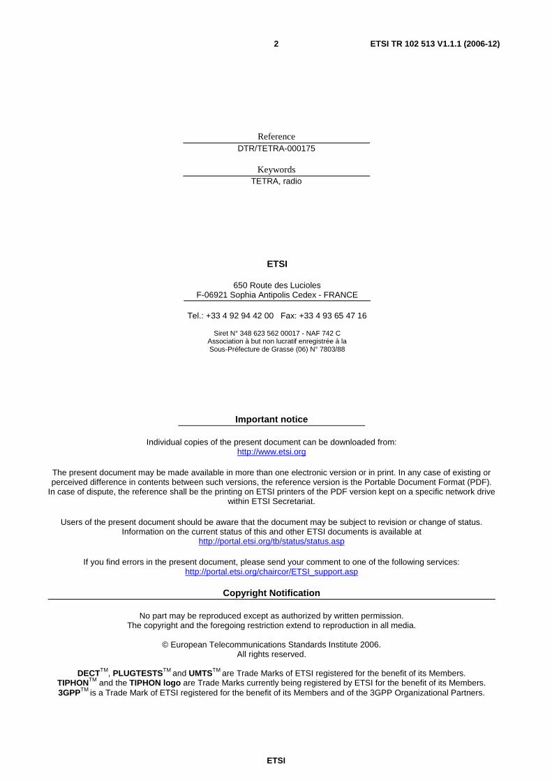
To determine the maximum and minimum frequency bandwidth requirements for transmitters and receivers at TETRA base station sites and for TETRA radio terminals, the frequency band allocations shown in figure 1 were used along with the minimum frequency spectrum requirement for TEDS.

ETSI
ETSI TR 102 513 V1.1.1 (2006-12) 8
380 390 400 410 420 430 450 460 470 440
MHz
Base Tx
Base Rx
KEY
Not Allocated
10
40
80
Figure 1: 380 MHz to 470 MHz frequency spectrum chart showing base station transmitter and receiver bands with maximum spectrum indicated for base station transmitters
For the purpose of calculation a minimum frequency bandwidth requirement used for TEDS is 2 x 1,05 MHz, this being the minimum requirement for wide area multiple site TEDS using 50 kHz RF bandwidth channels and a frequency re-use pattern of 21 (0,05 x 21 = 1,05). However, because TEDS could be assigned spectrum in any part of the 410 MHz to 430 MHz band and the 450 MHz to 470 MHz band, this study assumes that radio equipment switching bandwidths (tuning range) will be across the whole of these bands as designated for transmitter and receiver operation.
Because TEDS data channels are managed by the control channel of the TETRA V+D network, base station transmitter combining and receiver splitting systems as well as handportable and mobile radio terminals need to have wide RF bandwidth operation. For example, TETRA V+D will be operating in the 380 MHz to 385 MHz/390 MHz to 395 MHz band with TEDS operating somewhere in either the 410 MHz to 430 MHz band or the 450 MHz to 470 MHz band. Again, this fact will need to be taken into consideration for the purpose of calculation.
5.2 TETRA base station frequency spectrum considerations As a consequence of no common spectrum blocks, the maximum frequency switching bandwidth for TETRA V+D and TEDS base station transmitters and receivers can be seen in table 1, which were derived from the frequency spectrum chart in figure 1.
Table 1: Maximum base station transmitter and receiver RF bandwidths
Tx Frequency Band (MHz) Rx Frequency Band (MHz) Lower Limit
(MHz) Upper Limit
(MHz) Lower Limit
(MHz) Upper Limit
(MHz) Maximum Tx Bandwidth
(MHz) Maximum Rx
Bandwidth (MHz) 390 400 380 390 10,0 10,0 390 430 380 420 40,0 40,0 390 470 380 460 80,0 80,0
5.3 TETRA radio terminal radio spectrum considerations Because TETRA V+D radio terminals on PSS networks are always provisioned with single frequency Direct Mode Operation (DMO) channels, their transmitters and receivers are designed to operate across the whole of the 380 MHz to 400 MHz band to allow DMO use of either base station transmit or receiver frequencies when permitted. Even though DMO assignments are usually in the lower part of the frequency band this wideband DMO capability provides additional flexibility for frequency planning, especially on new networks.

ETSI
ETSI TR 102 513 V1.1.1 (2006-12) 9
This requirement means that TETRA V+D radio terminals provisioned with TEDS need additional RF bandwidth capability compared with base station site equipment. Even though TEDS, only radio terminals would not have DMO, every TETRA PSS Network would always have nationwide deployment of TETRA V+D and TEDS radio terminals. Taking these factors into consideration the maximum switching bandwidth requirements for radio terminal transmitters and receivers is provided in table 2.
Table 2: Maximum radio terminal transmitter and receiver RF bandwidths
Tx Frequency Band (MHz) Rx Frequency Band (MHz) Lower Limit
(MHz) Upper Limit
(MHz) Lower Limit
(MHz) Upper Limit
(MHz) Maximum Tx
Bandwidth (MHz) Maximum Rx
Bandwidth (MHz) 380 400 380 400 20,0 20,0 380 430 380 420 50,0 40,0 380 470 380 460 90,0 80,0
It may be possible to reduce the switching bandwidth required on individual base station sites for new TETRA networks by complementary frequency planning between channel assignments in the 380 MHz to 385 MHz/390 MHz to 395 MHz band with TEDS assignments in the 410 MHz to 430 MHz band and/or the 450 MHz to 470 MHz band (if appropriate spectrum allocations exist).
It may also be possible to reduce the switching bandwidth required on radio terminal equipment by minimizing the use of DMO and/or designating DMO channels around 390 MHz.
6 Implications on use of wideband mobile stations covering 380 MHz to 470 MHz
6.1 General For manufacturing economies of scale purposes, wideband Mobile Stations (MSs) covering 380 MHz to 430 MHz are already available from a number of TETRA manufacturers. However, operation across the whole of the 380 MHz to 430 MHz "tuning range" for wideband applications is untested. For operation across the 380 MHz to 470 MHz tuning range there are no MS products available. To develop MS products to operate across this tuning range would require the following considerations.
6.2 RF PA linearity Wider bandwidth Transmitter Voltage Controlled Oscillator (VCO) gives increased tuning sensitivity making the transmitter VCO more susceptible to modulation jitter from the TETRA transmit burst. This will negatively impact ACP performance. A switched VCO-synthesiser architecture may be needed to mitigate this susceptibility. A switched VCO-synthesiser architecture will increase manufacturing cost.
A broadband RF PA matching circuit will reduce RF PA efficiency or reduced ACP for a given DC power consumption. Also, broadband matching deviates from the optimum linearity match in the RF PA, which reduces efficiency for given ACP.
The possible use of a switched antenna for broadband operation increases the transmitter path insertion loss. Broadband harmonic filter requirements also add to the transmitter path insertion loss.
6.3 RF Wideband Noise Higher transmitter VCO phase noise will contribute to the ultimate wide band noise floor. Also, receiver VCO phase noise increase negatively impacts blocking performance.

ETSI
ETSI TR 102 513 V1.1.1 (2006-12) 10
6.4 Switching time between TETRA V+D and TEDS channels The increase in switching speed to ensure optimum channel selection performance would necessitate novel VCO architectures to be investigated.
6.5 Conclusions From the information provided in this clause the following conclusions can be drawn:
• Although wideband MSs covering 380 MHz to 430 MHz are already available, actual operation across the whole of the 380 MHz to 430 MHz "tuning range" for wideband applications is untested.
• For increased development and manufacturing cost reasons and possible reduced performance as well as reduced economies of scale (TEDS in Europe only) it is unlikely that any TETRA MS manufacturer will develop products spanning 380 MHz to 470 MHz.
6.6 Recommendations Based on the conclusions made in this clause it is recommended that tests are carried out across the tuning range 380 MHz to 430 MHz using existing wideband MSs.
7 Mobile station antenna implications
7.1 General Because TEDS data channels are assigned by the control channel of the TETRA V+D network, handportable and mobile radio terminals with TEDS need to have a wideband operation as indicated in the clause 5 (frequency spectrum considerations) of this feasibility study. This fact is true for TETRA V+D plus TEDS and TEDS only data terminals.
Handportable radio terminals operated in PSS TETRA Networks normally use either helical or ¼ wave whips. Mobile radio terminal installations normally use a ¼ rooftop antenna. However, for some applications specialist antennas are used, for example, fixed mobile installations, magnetic mount antennas, low profile antennas and many more. From antenna performance specifications the quoted frequency band of operation, VSWR, bandwidth and gain for the different antenna types used in TETRA are listed in table 3.
Table 3: Typical radio terminal antenna RF bandwidths
Antenna Type Frequency Band (MHz)
VSWR Bandwidth (%)
Bandwidth (MHz)
Gain (dBi)
Bracket Mount ½ Wave 380 to 400 2:1 8,0 32 4 Handportable (helical) 380 to 430 2:1 8,0 32 see note Handportable (¼ Wave) 380 to 430 2:1 10,0 40 see note Handportable (½Wave) 380 to 430 2:1 8,0 32 see note Low Profile 380 to 400 2:1 5,0 20 2 Magnetic Mount ¼ Wave 380 to 400 2:1 10,0 40 2 Vehicle Rooftop ¼ Wave 380 to 430 2:1 10,0 40 2 Motor Cycle (½Wave) 380 to 400 2:1 8,0 32 4 Wall Mount Dipole 380 to 400 2:1 8,0 32 2 NOTE: The gain of handportable radio antennas is not specified as it is dependent on a number of factors
such as ground plane characteristic and body worn parameters.
Also note that the bandwidth specification of the ½ wave bracket mount antenna is shown as 8 %, which is 32 MHz whilst the frequency band is specified as 380 MHz to 400 MHz (20 MHz bandwidth). For the purpose of this study operation only in the 380 MHz to 400 MHz band is assumed regarding this anomaly.

ETSI
ETSI TR 102 513 V1.1.1 (2006-12) 11
As can be seen from table 3, antenna operational bandwidths (for a VSWR of 2:1) range from 32 MHz to 40 MHz with the exception of the low profile antenna that is only 20 MHz. From clause 6, the maximum operational bandwidth for TEDS operating in the 410 MHz to 430 MHz band is 50 MHz and the maximum operational bandwidth for TEDS operating in the 450 MHz to 470 MHz band is 90 MHz.
7.2 Conclusions From the information provided in this clause the following conclusions can be drawn.
• All antenna types are unsuitable for single antenna working of PSS TEDS operating in the 410 MHz to 430 MHz frequency band and the 450 MHz to 470 MHz band.
• The only frequency band where all antennas are suitable for single antenna working is the 380 MHz to 400 MHz band.
• If the reduction in performance caused by operating antennas up to a maximum bandwidth of 50 MHz is acceptable, support of TEDS in the 410 MHz to 430 MHz band would be possible.
If the reduced performance is found to be unacceptable the obvious solution is for radio terminals to utilize two antennas. However, the use of two antennas on handportable and mobile radio terminals is considered unacceptable for the following reasons:
• Increased cost (two receivers and RF PA's).
• Increased size (two antennas and more electronics).
• Larger battery to support increased power consumption on handportable radio terminals.
• Reduced performance (RF propagation differences between two antennas).
• Impractical (size of antennas on handportable terminals and limited rooftop space for mobile radio terminal installations).
As many factors affect the performance of radio terminal equipment (mobile nature of use) and if communications are lost and/or degraded only one user is affected, reduced performance may be acceptable, however, field trials will be needed to quantify actual degradation.
The only other alternative to two antennas would be to encourage industry to develop a range of broadband antennas.
NOTE: For detailed information on the significance of VSWR (see annex A).
8 Base station antenna implications
8.1 General The base station antenna types used by Public Safety Sector (PSS) national TETRA networks in Belgium, Finland, The Netherlands and the UK (ASTRID, VIRVE, C2000 and Airwave respectively) are shown in table 4.
Table 4: Base Station Antenna Operational Bandwidths
Antenna Type Frequency Band (MHz)
VSWR Bandwidth (%) Bandwidth (MHz) Gain (dBi)
Collinear 380 to 410 1,5:1 7 28 8 Centre Fed Dipole 380 to 410 2:1 8 32 2 Folded Dipole 380 to 430 1,5:1 20 80 2 Panel (120 degree) 380 to 410 1,5:1 n/a 30 11

ETSI
ETSI TR 102 513 V1.1.1 (2006-12) 12
Besides these antennas, a number of cell enhancers and tunnel systems are also used to provide additional fixed network RF coverage. Although cell enhancers and tunnel systems are usually frequency selective they have not been considered in this study. The most common antenna used is the collinear as it provides good omni-directional RF coverage and most importantly high gain. For this reason, only the impact of using collinear antennas will be used in this study.
Because the useable RF bandwidth of a collinear antenna is 28 MHz (see table 7) it more than adequately covers the 10 MHz transmitter band of 390 MHz to 400 MHz, as well as the 380 MHz to 400 MHz receiver band, and therefore a single antenna system can be used for some applications. However, it is more common to use two antennas, one for the transmitters and one for the receivers located at a base station site.
Because the operationally acceptable bandwidth of collinear antennas is 28 MHz, one antenna cannot be used to support both TETRA V+D and TEDS transmitters spanning the frequency range 390 MHz to 430 MHz or TETRA V+D and TEDS transmitters spanning the frequency range 390 MHz to 470 MHz.
This said, it is theoretically possible to reduce the switching bandwidth required for single antenna working (separate Tx and Rx) on individual base station sites for new TETRA networks by complementary frequency planning between channel assignments in the 380 MHz to 385 MHz/390 MHz to 395 MHz band with TEDS assignments in the 410 MHz to 430 MHz band. In practice, as available spectrum in the 410 MHz to 430 MHz band is fragmented in most CEPT region countries and because frequency planning for existing TETRA networks did not take into consideration the need for expansion into other frequency bands it is highly unlikely that retrospective "complementary frequency planning" would be practical.
8.2 Conclusions From the information provided in this clause the following can be concluded:
• Two antenna systems (2 x Tx and 2 x Rx) are required at base station sites for a TETRA V+D and TEDS PSS network when TEDS is assigned to operate in the 410 MHz to 430 MHz band or the 450 MHz to 470 MHz band.
• One antenna system (1 x Tx and 1 x Rx) is acceptable for TETRA V+D and TEDS PSS network when TEDS is assigned to operate in the 385 MHz to 390 MHz/395 MHz to 400 MHz band.
NOTE: For detailed information on the significance of VSWR (see annex A).
9 Implications of transmitter combining and receiver splitting systems at TETRA base station sites
9.1 General The most costly and space demanding antenna system element at base stations sites is transmitter combining, which is required to enable single antenna working. Even though receiver splitting is required for single antenna working, this element is relatively inexpensive and less space consuming and will not be considered in this study.
Therefore, the reference transmitter combining systems used for this clause of the feasibility study is that used by the majority of exiting Public Safety TETRA V+D networks, as shown in figure 2.

ETSI
ETSI TR 102 513 V1.1.1 (2006-12) 13
Base Station Equipment Cabinet
Tx 1 Tx 2 Tx 3
Antenna Feeder
Antenna (7.5 dB)
Base Station Equipment Cabinet
4 dB
Tx 2
4 dB
Tx 3 Tx 1
Antenna Feeder
Antenna (7.5dB)
= Dummy Load
Typical Cavity Filter TX Combining Typical Hybrid TX Combining
4 dB
Figure 2: Representative Transmitter (Tx) combing configurations used for TETRA V+D in the 380 MHz to 400 MHz band
As can be seen from figure 2 the two transmitter combining networks used are hybrid combining when RF channels assignments are close together and cavity filter combining when channel assignment can be spaced greater that 150 kHz apart.
Note that cavity combing is more frequently used as it offers less attenuation and can handle greater RF transmitter powers. Both reference configurations are designed to support 12 logical TETRA channels (3 RF carriers).
9.2 TETRA V+D with a single 50 kHz TEDS channel Taking the reference transmitter combining configuration shown in figure 3, with one 50 kHz TEDS channel added, the additional equipment required for a 10 MHz transmitter switching bandwidth between 390 MHz and 400 MHz is shown in figure 3.

ETSI
ETSI TR 102 513 V1.1.1 (2006-12) 14
Base Station Equipment Cabinet
Tx 1 Tx 2 Tx 3 TEDS
Base Station Equipment Cabinet
4 dB
Tx 1
4 dB
Tx 3 TEDS
Tx
4 dB
Antenna Feeder
Antenna (7.5dB)
= Dummy Load
Tx 2
Typical Cavity Filter TX Combining Typical Hybrid TX Combining
Antenna Feeder
Antenna (7.5dB)
Figure 3: Representative Transmitter (Tx) combing configurations required for TETRA V+D and a TEDS transmitter operating in the in the 390 MHz to 400 MHz band
Because the 28 MHz (see clause 7) bandwidth of collinear antennas (most commonly used antenna for TETRA networks) more than adequately covers the 10 MHz transmitter band of 390 MHz to 400 MHz, as well as the 380 MHz to 400 MHz receiver band (using a separate antenna) a single antenna can be used for base station transmitters and receivers.
As can be seen from figure 3, the additional equipment required (coloured in blue) in the case of hybrid combining is only the TEDS transmitter as the dummy load is removed and the TEDS transmitter connected to the hybrid power splitter. In the case of cavity filter combining a TEDS transmitter, one cavity filter and matching cable harness is required. As space would probably exists in existing TETRA V+D Base Station equipment cabinets, field upgrades would be relatively inexpensive and practical to implement, especially as existing antenna networks would not need upgrading. In the case of new TETRA V+D and TEDS networks single antenna configurations would only be required.
Again, taking the reference transmitter combining configuration shown in figure 2, with one 50 kHz TEDS channel added, the additional equipment required for 40 MHz (maximum requirement from table 2 of clause 5) of bandwidth between 390 MHz and 430 MHz and a 80 MHz (maximum requirement from table 2 of clause 5) of bandwidth between 390 MHz and 470 MHz is shown in figure 4.

ETSI
ETSI TR 102 513 V1.1.1 (2006-12) 15
Base Station Equipment Cabinet
Tx 1 Tx 2 Tx 3 TEDS Tx
Base Station Equipment Cabinet
4 dB
Tx 1
4 dB
Tx 3 TEDS Tx
4 dB
Antenna Feeder
Antenna (7.5dB)
= Dummy Load
Tx 2
Typical Cavity Filter TX Combining Typical Hybrid TX Combining
Antenna Feeder
Antenna (7.5dB)
Antenna Feeder
Antenna (7.5dB)
Antenna Feeder
Antenna (7.5dB)
Figure 4: Representative Transmitter (Tx) combing configurations required for TETRA V+D in the 390 MHz to 400 MHz frequency band with a TEDS transmitter operating
in either the 410 MHz to 430 MHz band or the 450 MHz to 470 MHz band
Because the operationally acceptable bandwidth of collinear antennas is 28 MHz (see clause 7), one antenna cannot be used to support transmitters in the 390 MHz to 430 MHz band or transmitters in the 390 MHz to 470 MHz band. This means that two antenna systems (2 x Tx and 2 x Rx) are required at base station sites for a TETRA V+D and TEDS PSS network, which cause implications regarding cost, practicality and performance for existing PSS user organizations wishing to add TEDS to their existing TETRA Networks.
For example:
a) Cost: new antennas and feeders.
b) Practicality: adequate space, height and wind loading for additional antenna system.
c) Performance: matching RF coverage performance between TETRA V+D and TEDS.
The same implications as indicated in (b) and (c) also exist for new PSS user organizations wishing to implement TETRA V+D and TEDS.
9.3 Conclusions From the information provided in this clause the following conclusions can be drawn:
• The increased cost, impracticality and reduced performance for existing PSS user organizations wishing to add TEDS to their existing TETRA networks using either the 410 MHz to 430 MHz band of the 450 MHz to 470 MHz band may be considered prohibitive by some PSS organizations as well as new TETRA user organizations.

ETSI
ETSI TR 102 513 V1.1.1 (2006-12) 16
• There are no implications (other than minor costs) for existing PSS user organizations wishing to add TEDS to their existing TETRA networks using the 380 MHz to 400 MHz band.
10 Security implications of public safety sharing frequency bands used by non-public safety users
There are no known security implications of operating PSS TEDS in the 410 MHz to 430 MHz frequency band comparing with operating PSS TEDS in the 380 MHz to 400 MHz frequency band. This is because the basis of TETRA Air interface security measures lay in the strength of the encryption and the application of authentication, and as long as these are implemented correctly and that the encryption keys are changed before any repeat of the key-stream segment, there should be no significant risk. There would be no difference in the risks of operating in either frequency band despite the different types of neighbouring services.
11 TEDS channel bandwidth assignment implications
11.1 General This feasibility study has primarily looked at the implications of a wide area TEDS network comprising only one 50 kHz channel at each TETRA base station site. This is because if there are serious implications with the minimum TEDS requirement there will be serious implications with other configurations. However, this does not mean that if there are no serious implications with the minimum TEDS requirement there will be no serious implications with other expected configurations. For this reason there is a need to consider the full capability of TEDS for providing wideband data.
TEDS has been specifically developed to provide a choice of different modulations schemes and different RF channel bandwidths that can be utilized to provide optimum data transfer within narrow band PMR spectrum constraints. The range of modulation schemes, gross data rates and associated RF channel bandwidths can be seen in figure 5.
Channel Type
36
25 kHz 50 kHz 100 kHz 150 kHz
54
38
77
115
77
154
230
154
307
461
230
461
691
ππππ /4 DQPSK ππππ /8 DQPSK
4 QAM
16 QAM
64 QAM
Gross Data Rate (kbits/s)
NOTE: All channels are 4 slots.
Figure 5: TEDS modulation schemes, gross data rates and RF channel bandwidths
From figure 5, we can see that gross data rates range from 36 kbits/s up to 691 kbits/s and RF channel bandwidths from 25 kHz up to 150 kHz. To maximize the operational flexibility for increased data rates in specific geographic areas (such as cities) within the constraints of available frequency spectrum, RF channel bandwidths in excess of 50 kHz will be used.
NOTE 1: Modulation schemes are automatically selected based on signal quality levels.

ETSI
ETSI TR 102 513 V1.1.1 (2006-12) 17
This capability will maximize the spectrum efficiency of a high capacity TEDS network by only assigning capacity where it is more likely to be needed. For example, increasing RF channel bandwidth and allowing a higher level modulation scheme to be used without degrading RF range performance will increase data throughput capacity. Even so, this high capacity capability will place extra demands on radio frequency planning and also demand more radio frequency spectrum, not only by the increased RF channel bandwidth but also the use of higher modulation schemes affecting frequency re-use. For example, a 64 QAM modulation scheme requires a frequency re-use pattern of 33.
Some examples of this type of TEDS network are shown in table 5 below. For ease of explanation the maximum number of TEDS sites chosen for each type of network is 33, which is also the minimum radio frequency re-use factor for TEDS.
From table 5 we can see that if a PSS user organization wished to have the maximum possible wideband data capability across the whole of their network the spectrum required would be 2 x 4,95 MHz. Because user organizations are likely to utilize the automatic selection of different modulation schemes to increase data throughput when signal levels permit, the frequency re-use pattern will need to be 33 to allow for 64 QAM operation. This means in practice that even using 50 kHz RF bandwidth channels will require 2 x 1,65 MHz as shown in table 5.
NOTE 2: A frequency re-use factor of 21 has been used in other clauses of this study simply to indicate the minimum data.
To some organization this amount of data capacity may seem excessive, especially as existing PSS TETRA networks are using narrow band data services. However, with the increase in use of high definition image transfer, real time video, digital mapping and many more data application expected in the public safety environment and the need for adequate preparedness for Public Protection and Disaster Relief (PPDR) scenarios, these demands for high amounts of data are considered realistic, especially with the increased trend in Europe for shared public safety networks.
Table 5: TEDS Network RF spectrum requirements
Number of TEDS Base
Station Sites
Number of 50 KHz Channel TEDS
Sites (Low Capacity)
Number of 100 KHz
Channel TEDS Sites (Medium
Capacity)
Number of 150 KHz
Channel TEDS Sites (High Capacity)
Minimum Frequency
Re-use factor
Total RF Spectrum Required
(MHz)
33 0 0 33 33 4,95 33 12 11 10 33 3,20 33 21 7 5 33 2,50 33 33 0 0 33 1,65
11.2 Conclusion From the information contained in this clause, along with the conclusions in other clauses, it is reasonable to conclude the following:
• The provision of high capacity TEDS with its full dynamic flexibility is unlikely to be provided using frequency spectrum assignments in the 410 MHz to 430 MHz and 450 MHz to 470 MHz bands.
12 Spectrum efficiency implications of TETRA V+D and TEDS in the same frequency band versus TETRA V+D and TEDS in separate frequency bands
12.1 General The amount of frequency spectrum required by a TETRA network is important as the cost of spectrum and licences are on the increase as is the availability of spectrum for TETRA. Therefore, spectrum efficiency is very important as it directly relates to the amount of spectrum required to support a network of a specific Grade of Service (GoS).

ETSI
ETSI TR 102 513 V1.1.1 (2006-12) 18
Spectrum efficiency is a combination of occupied bandwidth required per communication channel and the number of times the same radio frequency can be reused in a wide area coverage network.
The three performance specifications that determine spectrum efficiency are the number of channels (or data throughput) per RF carrier, the RF channel occupied bandwidth and the Carrier to Interference (C/I) ratio, the latter determining the cellular re-use pattern (N) that can be used in a network. The formula for determining spectrum efficiency from these three performance specifications is.
NBandwithChannelRFOccupied
sChannelionCommunicattIndependenofNumberficiencySpectrumEf
×
=
In radio frequency bands dedicated solely to TETRA (no other technologies occupying the band), the above formula for spectrum efficiency holds true. However, in radio frequency bands where several technologies could be deployed other factors need to be considered, the most significant being the need for guard bands between co-existing technologies and frequency planning constraints.
For this reason only guard band requirements and radio frequency planning constraints will be considered as these will determined the difference in spectrum efficiency between TETRA V+D and TEDS operating in the 380 MHz to 400 MHz band.
12.2 Guard band requirements In the 410 MHz to 430 MHz band and the 450 MHz to 470 MHz band, technologies co-existing with TETRA could be conventional analogue FM, trunked MPT1327 analogue and Tetrapol. In the 450 MHz to 470 MHz band CDMA may also be a co-existing technology.
Even though results from the CEPT Project Team SE7 studies on co-existence are not yet known, it is logical to assume that guard bands will be required between TEDS and FDMA technologies for specific applications, even though the performance specifications (receiver sensitivity, RF power, channel bandwidth, Adjacent Channel Power) between the two technologies are similar.
NOTE: The impact of co-existence with CDMA technologies will not be considered in this study.
For example, if TEDS and FDMA base stations serving the same geographic area were located on different base station sites it is possible that TEDS base station sites could be located within the medium to low signal strength areas of a FDMA base station site, especially if the TEDS network was providing coverage for handportable terminals whereas the FDMA sites was providing coverage only for vehicle borne mobile equipment. Obviously, if TEDS and FDMA base stations were located on the same site guard bands would probably not be required.
Another important consideration is the interference aspects of sharing with narrow band services in 410 MHz to 430 MHz and 450 MHz to 470 MHz bands. For example, the wideband operation of TEDS in these bands will raise the noise floor for narrow band users. In the large cities of Europe the noise floor is often within 4 dB of the point where loss of range will be apparent.
It is important to note that these observations are to be considered indicative only and actual study work by CEPT Project Team SE7 will determine the acceptable levels of interference, balanced with guard bands, if required.
12.3 Radio frequency planning constraints In the examples used in this part of the study, the value of N used for TEDS deployments is 21.
The standard frequency planning method for providing wide area multiple site RF coverage is to use an appropriate cellular frequency re-use pattern, which for the purpose of this TEDS example is as shown in figure 6.

ETSI
ETSI TR 102 513 V1.1.1 (2006-12) 19
1 2 3 4 5 6 7 8 11 12 13 14 15 16 17 18 19 20 21
KEY
1 = 50 kHz TEDS Channel
= 12.5 kHz FDMA Channel
50 kHz Guard Band
50 kHz Guard Band
Figure 6: TEDS RF coverage using a contiguous block of 21 x 50 kHz channels
From figure 6 it can be seen that a guard band is required at each end of the contiguous block. For the purpose on example only, if a guard band requirement of 50 kHz is assumed, then only a total of 100 kHz of spectrum is in effect wasted. This contiguous block is the most spectrum efficient method to be used for wide area multiple base station site RF coverage. However, if a contiguous block of 2 x 1,05 MHz (21 x 50 kHz channels for transmit and receive) cannot be provided, spectrum efficiency gets worse as can be seen in figure 7.
1 2 3 4 5 19 20 21
KE
1 = 50 kHz TEDS Channel
= 12.5 kHz FDMA Channel
50 kHz Guard 50 kHz Guard
17 18
50 kHz Guard 50 kHz Guard 50 kHz Guard
Figure 7: TEDS RF coverage with interleaved guard bands
As can be seen from figure 7, the amount of spectrum wasted as a result of interleaving TEDS channels between existing FDMA technology deployments compared with the contiguous block assignment example in figure 6, is 300 kHz.
A comparison of the examples in figures 6 and 7 with a contiguous block TEDS radio frequency assignment in an exclusive TETRA radio frequency band are shown in table 6.

ETSI
ETSI TR 102 513 V1.1.1 (2006-12) 20
Table 6: Spectrum efficiency comparison TETRA Band versus Non-TETRA Band
Type of TEDS Network
Number of TEDS Channels
Number of 50 kHz FDMA Guard Bands
Wasted Frequency
Spectrum (MHz)
Overall Efficiency
(%) TEDS in exclusive TETRA band 21 0 (Ref.) 0 100 TEDS in non-exclusive frequency band using contiguous block
21 2 0,1 91
TETRA in non-exclusive frequency band with interleaved guard bands
21 8 0,4 72
From table 6 it can be seen that the most spectrum efficient implementation for TEDS is in a frequency band exclusively assigned for TETRA.
12.4 Conclusion From the information provided in this clause the following conclusion can be drawn.
The most spectrum efficient implementation for TEDS is in a frequency band exclusively assigned for TETRA.
13 Propagation and coverage implications of the control channels and TEDS channels being in different frequency bands
13.1 General Many factors affect RF propagation and RF coverage. But in the case of comparing the implications of TEDS operating in 410 MHz to 430 MHz and/or 450 MHz to 470 MHz, only the affects of radio frequency differences need to be investigated, these being path loss and wavelength.
13.2 Path loss differences The formula for Free Space Loss (FSL) = 20log (4πd/λ) [dB].
NOTE: Gives power received by isotropic antenna.
Table 7 uses this formula to calculate the free space propagation loss difference between 390 MHz, 420 MHz and 460 MHz, these being the lowest base station transmit frequencies for these bands.
Table 7: Free space propagation loss differences
D in km 20 20 20 f in GHz 0,39 0,42 0,46
Constant 88,15 88,15 88,15 20log(f) -8,18 -7,54 -6,74 20log(D) 26,02 26,02 26,02 dB loss 105,99 106,64 107,43
Difference (dB) 0 (Ref.) -0,64 -1,43
From table 7 it can be see that the difference in frequency band operation introduces little difference compared with other factors such as multi-path and shadow loss and can therefore be ignored.

ETSI
ETSI TR 102 513 V1.1.1 (2006-12) 21
13.3 Wavelength differences The main concern regarding the effect of wavelength differences is for mobile radio users and handportable radio user who are stationary or moving very slowly. For example, the signal received from the TETRA V+D control channel could be adequate but because of the wavelength difference effect on multi-path the signal from the TEDS base station located at the same TETRA V+D base station site could be unusable resulting in potential operational problems. However, from table 8, the differences in wavelength differences are unlikely to cause significant operational problems.
Table 8: Wavelength differences
Frequency (MHz) 390 420 460 Wavelength (cm) 76,9 71,4 65,2 Difference (cm) 0 (Ref.) 5,5 11,7
13.4 Conclusion From the information provided in this clause the following conclusion can be drawn.
No significant implications from path loss and wavelength differences.
14 Implications of two antenna system working at base station sites
14.1 General From clause 8, base station antenna implications, it is concluded that two independent antenna systems (2 x Tx and 2 x Rx) are required at base station sites for a TETRA V+D and TEDS PSS network when TEDS transmitters and receivers are assigned to operate in the 410 MHz to 430 MHz band or the 450 MHz to 470 MHz band. As a consequence this creates:
• Additional cost.
• Additional space, weight and wind loading on radio masts.
• Difference in RF coverage characteristics.
• Environmental impact.
14.2 Additional cost The cost of a TETRA antenna system is significant when low loss feeder and phased collinear antenna configurations are used to maximize omni-directional coverage. Also, as several antenna sites are not owned by PSS user organizations, a rental fee is paid for base station site facilities. In these cases, the need to have two antenna systems would significantly increase rental fees.
14.3 Additional space, weight and wind loading on radio masts The majority of base station sites used for wide area TETRA coverage are established antenna sites supporting several wireless technologies. Obtaining adequate space and height on established antenna sites is often difficult and obtaining space and adequate height for two antenna systems is in many cases not possible. Therefore, if a radio mast does not have sufficient space and/or wind loading capacity for two antenna systems, a new mast will need to be provided and/or an alternative antenna site found. If an alternative site needs to be found, it may not be ideally located and could therefore compromise RF coverage. For existing PSS users of TETRA upgrading to TEDS, finding an alternative antenna site or building a new stronger mast will introduce "down time" and could severely impact communications. Also, additional costs would be incurred in relocating existing equipment to the new antenna site or mast.

ETSI
ETSI TR 102 513 V1.1.1 (2006-12) 22
14.4 Difference in RF coverage characteristics Because two antenna systems are needed they will be located at different heights on a radio mast. This means there are likely to be differences in RF coverage characteristics between the 380 MHz to 385 MHz/390 MHz to 395 MHz and 410 MHz to 430 MHz antenna systems. This difference could impact performance especially as the control channel managing TEDS resources is operating in the 380 MHz to 385 MHz/390 MHz to 395 MHz band and the actual TEDS resources being used are operating in the 410 MHz to 430 MHz band.
14.5 Environmental impact Already the proliferation of antenna mast is becoming unacceptable and tight controls are being placed on new antenna site developments. Therefore the need to develop new sites to accommodate two antenna systems is going to be difficult. The use of existing sites to accommodate two antenna systems can also impact the environment.
14.6 Conclusions From the information provided in this clause, the following can be concluded.
• The need for two independent antenna systems (2 x Tx and 2 x Rx) at base station sites is unacceptable for a TETRA V+D and TEDS PSS network, when transmitters and receivers are assigned to operate in the 410 MHz to 430 MHz band or the 450 MHz to 470 MHz band.
15 Alternative solutions
15.1 General From clause 15, implications of two antenna working at base station sites, it was concluded that two independent antenna systems (2 x Tx and 2 x RX) at base station sites for a TETRA V+D and TEDS PSS network, when TEDS transmitters and receivers are assigned to operate in the 410 MHz to 430 MHz band or the 450 MHz to 470 MHz band, is unacceptable.
Recognizing that the deployment of PSS TEDS is required there are two possible solutions that can be considered, these being as follows.
15.1.1 Split band: solution 1
This solution is only practical and acceptable for new TETRA users and is not suitable for existing PSS users of TETRA wishing to upgrade to TEDS or to expand their V+D service. To remove the need for two independent antenna systems at each TETRA base station site a decision is made during the network planning phase to assign chosen base stations sites to operate in either the 380 MHz to 385 MHz/390 MHz to 395 MHz band or the 410 MHz to 430 MHz band.
NOTE: Assumes radio terminals can operate across 380 MHz to 430 MHz with acceptable degradation but not 380 MHz to 470 MHz.
This solution means that each base station site will only need one antenna system (1 x Tx and 1 x Rx). However, this solution does create five problems as follows:
• Problem 1: Solution needed for existing users wishing to upgrade to TEDS.
• Problem 2: The availability of sufficient frequency spectrum in the 410 MHz to 430 MHz band for TETRA V+D and TEDS combined.
• Problem 3: Spectrum in the 380 MHz to 385 MHz/390 MHz to 395 MHz band not fully utilized (half and/or part of network capacity supported in the 410 MHz to 430 MHz band and non-uniform geographic coverage).

ETSI
ETSI TR 102 513 V1.1.1 (2006-12) 23
• Problem 4: Insufficient spectrum remaining in the 410 MHz to 430 MHz band for non-public safety TETRA networks.
• Problem 5: Non-uniform distribution of spectrum allocations in the 410 MHz to 430 MHz band.
• Problem 6: Radio terminal switching/searching times for control channels located in either the in 380 MHz to 385 MHz/390 MHz to 395 MHz band or the 410 MHz to 430 MHz band.
The main reasons why this solution is not acceptable for existing TETRA user organizations wishing to upgrade to TEDS are as follows:
a) New frequency planning required.
b) Base station sites will need antennas to be replaced.
c) Some base stations operating in the 380 MHz to 385 MHz/390 MHz to 395 MHz band will need to be replaced with base stations that operate in the 410 MHz to 430 MHz band.
d) Some base stations operating in the 380 MHz to 385 MHz/390 MHz to 395 MHz band will need to be retuned to other operating frequencies in the same band.
e) All V+D radio terminals will need replacing so that they can operate in either the 380 MHz to 385 MHz/390 MHz to 395 MHz band or the 410 MHz to 430 MHz band.
f) Disruption to communications as changes take place.
15.1.2 Single band: solution 2
The preferred solution is one harmonized frequency band allowing single antenna system (1 x Tx and 1 x Rx) operation with sufficient capacity to support both TETRA V+D and TEDS for both existing and future PSS users of TETRA. For example, the 380 MHz to 385 MHz/390 MHz to 395 MHz band combined with sufficient spectrum from the adjacent 385 MHz to 390 MHz/395 MHz to 400 MHz band.
15.2 Conclusions From the two solutions described the following conclusions can be drawn:
• The split band solution is suitable for new PSS users when sufficient spectrum is available in the 410 MHz to 430 MHz band and sufficient spectrum remains for non-public safety users of TETRA.
• The split band solution is not suitable for existing PSS users of TETRA wishing to upgrade to TEDS.
• The single band solution is the only practical solution that meets the needs of existing PSS users of TETRA wishing to upgrade to TEDS.
16 Overall conclusions Each clause in this study contains its own individual conclusions. In considering all these individual conclusions the most significant and important conclusions are as follows:
• From clause 6: Implications on use of wideband mobile stations Covering 380 MHz to 470 MHz:
- Although wideband MSs covering 380 MHz to 430 MHz are already available, actual operation across the whole of the 380 MHz to 430 MHz "tuning range" for wideband applications is untested.
- For increased development and manufacturing cost reasons and possible reduced performance as well as reduced economies of scale (TEDS in Europe only) it is unlikely that any TETRA MS manufacturer will develop products spanning 380 MHz to 470 MHz.

ETSI
ETSI TR 102 513 V1.1.1 (2006-12) 24
• From clause 7: Mobile station antenna implications:
- If the reduction in performance caused by operating radio terminal antennas up to a maximum bandwidth of 50 MHz is acceptable, support of TEDS in the 410 MHz to 430 MHz band would be possible.
• From clause 8: Base station antenna implications:
- Two antenna systems (2 x Tx and 2 x Rx) are required at base station sites for a TETRA V+D and TEDS PSS network when TEDS is assigned to operate in the 410 MHz to 430 MHz band or the 450 MHz to 470 MHz band.
- One antenna system (1 x Tx and 1 x Rx) is acceptable for TETRA V+D and TEDS PSS network when TEDS is assigned to operate in the 385 MHz to 390 MHz/395 MHz to 400 MHz band.
• From clause 14: Implications of two antenna system working at base station sites:
- The need for two independent antenna systems (2 x Tx and 2 x Rx) at base station sites is unacceptable for a TETRA V+D and TEDS PSS network, when TEDS transmitters and receivers are assigned to operate in the 410 MHz to 430 MHz band or the 450 MHz to 470 MHz band.
• From clause 15: Alternative solutions:
- The split band solution is suitable for new PSS users when sufficient spectrum is available in the 410 MHz to 430 MHz band and sufficient spectrum remains for non-public safety users of TETRA.
- The split band solution is not suitable for existing PSS users of TETRA wishing to upgrade to TEDS.
- The single band solution is the only practical solution that meets the needs of existing PSS users of TETRA wishing to upgrade to TEDS.
The most significant conclusion from this study is that use of the 380 MHz to 385 MHz/390 MHz to 395 MHz band combined with sufficient spectrum from the adjacent 385 MHz to 390 MHz/ 395 MHz to 400 MHz band should be made available to support TETRA V+D and TEDS as this is both the optimum and preferred solution.
17 Recommendations The recommendations resulting from the findings and conclusions of this study have resulted from the analysis carried out in clause 7 and are as follows:
a) A field trial is carried out using a number of different handportable and mobile radio antenna types to establish if antenna performance is acceptable across a frequency bandwidth of 50 MHz this being the maximum RF bandwidth required for the support of TEDS in the 410 MHz to 430 MHz band.
b) If the field trial in (a) concludes that antenna performance is not acceptable, the TETRA Industry should request the antenna industry to develop a range of radio terminal compatible broadband antennas.
c) MS performance tests (independent of antenna performance) are carried out across the tuning range 380 MHz to 430 MHz using existing wideband MSs.
The most important recommendation in this report is for the CEPT ECC WGFM to continue exploring the possibility of assigning adequate frequency spectrum from the 385 MHz to 390 MHz/395 MHz to 400 MHz band to accommodate TEDS.

ETSI
ETSI TR 102 513 V1.1.1 (2006-12) 25
Annex A: Antenna performance specifications
A.1 General The types of antennas used in TETRA are chosen for a number of factors. With regard to broadband operation the most important performance specification is the Voltage Standing Wave Ratio (VSWR) as this is commonly used to specify bandwidth limits.
To better understand the usefulness of VSWR specifications in defining bandwidth limits, there is a need to look at this specifications relationship regarding forward and reflected power. In order to do this, a ratio known as Rho needs to be calculated. Once Rho is known the VSWR can be calculated. Another specification often used in antenna specifications is Return Loss, expressed in dBs. Both VSWR and Return Loss are complex ratios of forward and reflected power. An explanation of VSWR, containing examples of both Rho and Return Loss, is provided below.
A.2 VSWR This specification calculation is used to indicate how well an antenna of a given characteristic impedance and operating frequency will be matched to a transmitter or receiver of the same characteristic impedance connected together using a transmission line of the same characteristic impedance. The lower the VSWR the better the antenna performance and therefore the greater the power transfer between antenna and connected transmitter and receiver. The higher the VSWR the less efficient the antenna as impedance mismatch occurs and RF power is reflected.
Antennas are radio frequency sensitive and are tuned at manufacture to a specific radio frequency of operation, often referred to as the centre frequency. As a consequence, the VSWR normally increases when antennas are operated using radio frequencies "above and below" the optimum radio frequency. VSWR curves are usually not symmetrical. They can rise faster on one end of the band than the other and can have more than one low portion. Two typical curves are shown in figure A.1.
VSWR VSWR
Frequency Spectrum Frequency Spectrum
Figure A.1: Typical antenna VSWR curves
Because VSWR is a good indication of antenna efficiency across a range of radio frequencies it is used to indicate the operational bandwidth of antennas. For base station antennas a VSWR of 1.5:1 is often quoted as the specification used to determine bandwidth. For radio terminal antennas a VSWR of 2.0:1 is often quoted.
The formula to calculate VSWR from values of Rho is:
VSWR = (1 + Rho) / (1 - Rho)
The formula used to calculate Rho is:
(Reflected Power (W) / Forward Power (W)) Rho =
For example, with a forward power of 100 W and reflected power of 4 W, Rho = 0.2.
Taking this value of Rho in the VSWR calculation we have:
VSWR = (1 + 0.2)/(1 - 0.2) = 1.5. As a VSWR ratio this becomes 1.5:1.
From this example we allow up to 4 % of forward power to be reflected, which happens to be the figure used in industry to specify bandwidth limits of base station antennas.

ETSI
ETSI TR 102 513 V1.1.1 (2006-12) 26
Table A.1 lists Rho, VSWR and Return Loss calculations for reflected powers ranging from 1 Watt to 50 Watts with a forward power of 100 Watts.
Table A.1: Rho, VSWR and return loss calculations
Reflected Power (W)
Forward Power (W)
Rho
VSWR
Return Loss (dB)
1 100 0,10 1,2 -20 2 100 0,14 1,3 -17 3 100 0,17 1,4 -15 4 100 0,20 1,5 -14 5 100 0,22 1,6 -13
10 100 0,32 1,9 -10 11 100 0,33 2,0 -10 12 100 0,35 2,1 -9 13 100 0,36 2,1 -9 14 100 0,37 2,2 -9 15 100 0,39 2,3 -8 20 100 0,45 2,6 -7 25 100 0,50 3,0 -6 30 100 0,55 3,4 -5 35 100 0,59 3,9 -5 40 100 0,63 4,4 -4 45 100 0,67 5,1 -3 50 100 0,71 5,8 -3
On inspection this 1.5:1 VSWR limit seems very conservative and some might say that operating beyond this specification limit will not seriously affect actual RF coverage performance. For example, degrading RF coverage performance by 1 dB (10 % of RF power reflected) would calculate to a VSWR of 1.9:1.
However, relaxing specification performance is not generally acceptable as network coverage is designed in the majority for TETRA networks using high gain antennas, which by nature have limited bandwidth. Also, antenna manufacturers only specify the 1.5:1 VSWR figure for bandwidth purposes on base station antennas, which means further tests would be needed by antenna manufacturers to specify VSWR figures across a wider bandwidth of operation and ensure that antenna performance is consistent for all antennas manufactured. This said, it is unlikely that selecting a higher VSWR will give a proportionate increase in operational bandwidth, for example, a VSWR of 3.0:1 will not double the bandwidth compared with a VSWR of 1.5:1. In practice, the increase in bandwidth is expected to be less than double.
Another factor of more importance is dissipating the RF power reflected and the impact this has on efficiency, equipment design and reliability. For example, wasted power increases utility costs and increases equipment room temperatures that need to be maintained in hot climatic conditions, which also increases utility costs (air conditioning).
Equipment needs to be designed to handle and dissipate extra heat. Also excessive heat is known to reduce equipment reliability. In some cases antenna impedance mismatch can result in reduced linearity performance of RF Power Amplifiers in TETRA transmitters resulting in interference.
Taking these factors into consideration, as well as other unknowns, it would be prudent not to operate antennas outside the bandwidth limits specified.
A.3 Conclusions Base on the information provided in this clause the following is concluded:
• Only operating within the bandwidth limits as specified for base station antennas up a VSWR of 1.5:1 is permitted.
• Only operating within the bandwidth limits as specified for radio terminal antennas up a VSWR of 2.0:1 is permitted.

ETSI
ETSI TR 102 513 V1.1.1 (2006-12) 27
Annex B: Bibliography TETRA 270621: "LS to FM38 Regarding Tuning Range Concept in 380 MHz to 430 MHz".

ETSI
ETSI TR 102 513 V1.1.1 (2006-12) 28
History
Document history
V1.1.1 December 2006 Publication