Embed Size (px)
Citation preview

+Energy Storage
References
1-ENERGY STORAGE FOR POWER SYSTEMS by Ter-Gazarian
2-Energy storage by Prof. Dr. Robert A. Huggins
3-THERMAL ENERGY STORAGE by ˙Ibrahim Dincer and Marc A. Rosen
1.1 Introduction
In addition to the inevitable depletion of the fossil fuels that are now the major sources of energy, and the relatively smaller current alternatives, there is another matter that is very important in considering the effective use of the energy that is available. This is the relationship between the several types of energy supplies and the various uses of energy. Worldwide energy consumption is between 500 and 600 EJ . In terms of consumption rate, this is 15–18 TW (1.5–1.8 _ 1013 W). The United States consumes about 25% of the total, although its share of the World’s population is about 5%. A recent estimate of the major United States sources of energy is shown in Table 1.1. The current distribution of energy use, by major category, is indicated in Table 1.2. These different types of applications have different requirements for access to energy, and different characteristics of its use. One of the important problems with the effective use of available energy supplies is that the schedule of energy use is often not synchronous with its acquisition, even from natural sources. Thus, buffer, or storage systems are necessary. This requirement for storage mechanisms is highly dependent upon the type of use. Those that use fossil fuels, or their derivatives, for combustion purposes, such as for space heating or internal combustion-powered automobiles, require one type of storage and distribution system. Another, quite different, category involves the various applications that acquire their energy from the large-scale electric power transmission and distribution (T&D) grid. In that case, there are two types of storage systems to consider. One has to do with the electric power grid system itself, and the time dependence of its energy supplies and demands, and the other has to do with storage mechanisms applicable to the various systems and devices that acquire their energy from the grid.
1

2

Two important physical media for storage and regulation of thermal energy are
water and hydrogen. Table 8.1 lists some thermo physical properties of water and
3

hydrogen, including the heats of formation of water in liquid and vapor states. Their material and thermophysical properties make them unique in not only storing and transforming energy but also regulation of the temperature of the earth.
Hydrogen represents a store of potential energy which can be released by nuclear fusion in the sun in the form of light. Solar energy may be stored as chemical energy by photosynthesis after it strikes the earth. Also, when water evaporates from oceans and is deposited high above sea level, it drives turbine/generators to produce electricity, hence sunlight may again be stored as gravitational potential
energy.
1. Water
Before the lecture; consider the following;
1-why water is preferred as a means to store energy?
2-what type of energy it stores?
3- what conditions water can store?
Approximately 80% of the earth’s surface is water. Water has a high specific heat capacity of 4.185 kJ/kg. C, which is much higher than that of soil and rock (see Table 8.1). Water can retain and store a large amount of heat per volume
Figure 1: water cycle
4

making the oceans the world’s massive temperature regulator. Therefore, the temperature of water changes more slowly than that of the earth’s surface. In addition, water has large heat of vaporization of around 2,257 kJ/kg at 20_C. This means that a large amount of latent heat can be transferred over long distances in vapor form and released after condensing as rain (see Fig.1). Accumulation of rain at high elevation reservoirs stores of large amounts of potential energy, which drives turbines to produce electricity. The oceans control the earths’ energy balance as they absorb nearly four times more insolation than the earth. Liquid water also helps to control the amount of carbon dioxide in the atmosphere by dissolving it into the form of ‘‘carbonic acid’’ (soda water). Some of the dissolved carbon dioxide combines with minerals in the water and settles to the ocean floor to form limestone. Water is also essential for all life-forms as most animals and plants contain more than 60% of water by volume, which helps organisms to regulate their body temperature. Therefore, water regulates the temperature of the earth as well as the temperature of living systems.
2.Hydrogen
1-why hydrogen is used in the energy sector?
2-where it can be stored?
3-how can we capture hydrogen?
Hydrogen is a versatile storage medium due to its conversion to useful work in a fuel cell to produce electricity as well as its usage in an internal combustion engine. Hydrogen is also being developed as an electrical power storage medium. It must first be manufactured by other energy sources and may become a significant energy storage medium in using renewable energies. Hydrogen can be manufactured by steam reforming of natural gas. When manufactured by this method it is a derivative fuel like gasoline. When produced by electrolysis of water, it is a form of chemical energy storage. About 50 kWh (180 MJ) of solar energy is required to produce 1 kg of hydrogen. At an electricity cost of $0.09/ kWh, hydrogen costs around $4.50/kg. Large quantities of gaseous hydrogen can be stored in underground caverns and in depleted oil or gas fields for many years, and can function as multipurpose energy storage.
Types of Energy Storage
On what factors energy storage is chosen?
The method of energy storage may be chosen on the basis of stability, ease of transport, energy capture, and release. The main energy storage technologies involve the storage of energy in thermal, electrical, chemical, and mechanical forms:
• Thermal. Thermal energy can be stored by sensible and latent heats at temperatures above or below the ambient temperatures. Heat is also stored for short or long-term applications. Thermal energy from the sun, for
5
example, can be captured by solar collectors and stored in a reservoir for daily or seasonal use. Thermal energy for cooling can be stored in ice.
• Electrical. Dams can be used to store hydroelectricity by accumulating large
amounts of water at high altitudes. The water then turns a turbine and generates
electricity. Also by using pumped-storage hydroelectricity stores energy by
pumping water back into the reservoir. A capacitor can store electric charge as a
part of electrical energy production system. Batteries can also store electric
energy to be used in portable electrical devices.
• Chemical. Stable chemical compounds such as fossil fuels store chemical
energy. Biological systems can store energy in chemical bonds of energy-rich
Thermal Energy Storage
Thermal energy storage technologies balance the energy demand and energy production. For example, the solar energy would be available during the night time or in the winter season if it is stored previously. Also a stored and transformed energy can be used somewhere else different from the location where it is captured or produced. The thermal storage medium may be maintained at a temperature above (hotter) or below (colder) that of the ambient temperature of 25_C. In hot climates, the primary applications of thermal energy storage are cold storage because of large electricity demand for air conditioning. Thermal energy storage may be planned for short term or seasonal. Some advantages of utilizing thermal energy storage are :
• Reduced energy consumptions and carbon footprint.
• Reduced initial equipment and maintenance costs.
• Reduced pollutant emissions such as CO2.
• Increased flexibility of operation, efficiency, and effectiveness of equipment
utilization.
• Process application in portable and rechargeable way at the required
temperature.
• Isothermal and higher storage capacity per unit weight.
• Energy from any source (thermal or electrical) when needed.
6

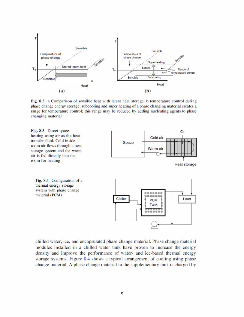
Thermal energy is generally stored in the form of sensible heat and latent heat. Figure 8.2 compares the characteristics of heat storage by sensible and latent heats. Temperature keeps increasing as a material absorbs and store sensible heat until it reaches a temperature where a phase changing occurs. Under their melting points, the solid-liquid phase changing materials store sensible heat and their temperature rises as they absorb the heat (see Fig. 8.2a). When phase changing materials reach their melting temperature they absorb large amounts of latent heat at an almost constant temperature until melting is completed. If the outside heat supply continues, then the melted material starts to store sensible heat. A material may freeze at a temperature lower than its actual freezing temperature. This is called subcooling. Also, a material may melt at a temperature higher than its actual melting temperature. This is called superheating. Subcooling and superheating of a phase changing material create an interval for temperature control (see Fig. 8.2b). This temperature interval between the subcooling and superheating may be reduced by adding nucleating agents to phase changing material. Stored heat is usually transferred to a heat transfer fluid such as water or air in a heat exchanger system as seen in Fig. 8.3. When air is used as heat transfer fluid, the cold inside room air extracts the heat as it flows through a heat storage system and the warm air out of the storage is fed directly into the room.
Night time low-cost electricity may be used to store energy as sensible heat or/ and latent. The stored energy is then used for the cooling/heating needs during the peak demand hours. Thermal energy storage systems can be designed using
7

There are three basic methods for storing thermal energy:
8
Methods of Thermal Energy Storage
1. Heating a liquid or a solid, without changing phase: This method is called sensible heat storage. The amount of energy stored depends on the temperature change of the material and can be expressed in the form
E= m ∫T 1
T 2
CpdT
where m is the mass and Cp; the specific heat at constant pressure. T1 and T2 represent the lower and upper temperature levels between which the storage operates. The difference (T2 – T1) is referred to as the temperature swing.
2. Heating a material, which undergoes a phase change (usually melting): This is called latent heat storage. The amount of energy stored (E) in this case depends upon the mass (m) and latent heat of fusion (λ) of the material. Thus,
E=mλ
The storage operates isothermally at the melting point of the material. If isothermal operation at the phase change temperature is difficult, the system operates over a range of temperatures T1 to T2 that includes the melting point. The sensible heat contributions have to be considered and the amount of energy stored is given by
where Cps and Cpl represents the specific heats of the solid and liquid phases and T* is the melting point.
Sensible Heat Storage
cooling a liquid or a solid, which does not change its phase during this process. A variety of substances have been used in such systems. These include liquids like water, heat transfer oils and certain inorganic molten salts, and solid like rocks, pebbles and refractory. In the case of solids, the material is invariably in porous form and heat is stored or extracted by the flow of a gas or a liquid through the pores or voids.
The choice of the substance used depends largely on the temperature level of the application, water being used for temperature below 100°C and refractory bricks being used for temperatures around 1000°C. Sensible heat storage systems are simpler in design than latent heat or bond storage systems.? However they suffer from the disadvantage of being bigger in size. For this reason, an important criterion in selecting a material for sensible heat storage is its (ρCp) value. A second disadvantage associated with sensible heat systems is that they cannot store or deliver energy at a constant temperature. We will first take up for consideration the various materials used.
9

Performance of a TES characterized by storage capacity, heat input and output rates while charging and discharging, and storage efficiency. The storage capacity of an SHS with a solid or liquid storage medium is given by
Q=mcdT =Vpcpdt
where m is mass, V is volume, c is specific heat, ρ is density and ΔT = Tmax-Tmin is maximum temperature difference between maximum and minimum temperatures of the medium. This expression can be used to calculate the mass and volume of storage material required to store a given quantity of energy. For a packed bed used for energy storage, the porosity of the bed must be taken into consideration and neglecting the heat capacity of the energy transferring medium in the storage the volume of the packed bed storage is written as
where ε is the porosity of the packed bed. The storage energy density per unit mass and the storage energy density per unit volume are respectively, defind as:
Example:
Sensible heat storage calculations
10

Problems
1.
(a) Estimate sensible heat stored in 6 m3 water and 6 m3 granite heated
from 20 to 400C.
(b) Estimate the heat stored in 500 lb of water heated from 20 to 30F.
2. (a) Estimate sensible heat stored in 1.1 m3 Dowtherm A and 1.1 m3
therminol 66 heated from 20 to 240_C.
(b) Estimate the heat stored in 500 lb of molten salt heated from 150 to
300C.
3. (a) Estimate sensible heat stored in 2.5 m3 mixture of 50% ethylene glycol
and 50% water heated from 20 to 65_C.
(b) Estimate the heat stored in 1,500 lb of draw salt heated from 250 to
400C.
11

Latent Heat Storage by Phase Changing Material
Latent heat storage can be achieved through solid–solid, solid–liquid, solid–gas, and liquid–gas phase changes. Liquid–gas transitions have a higher heat of transformation?? than solid–liquid transitions. However, liquid–gas phase changes are not practical because of the large volumes or high pressures required to store the materials when they are in their gas phase states. Solid–solid phase changes are
typically very slow and have a rather low heat of transformation. Therefore, the main phase change used for heat storage is the solid–liquid change. Figure 8.6 shows the change of enthalpy of water from solid to vapor state on enthalpy temperature diagram. Between -30 and 0_C the sensible heat of water increases. At 0_C the water starts to melt by absorbing heat of melting. After the melting is completed, the liquid water is heated until 100C.
Phase changing materials used for storing heat are chemical substances that undergo a solid–liquid transition at temperatures within the desired range for heating and cooling purposes. During the transition process, the material absorbs energy as it goes from a solid to a liquid state and releases energy as it goes back to a solid from liquid state. A phase changing material should possess:
• Melting temperature in the desired operating temperature range.
• High latent heat of fusion per unit volume.
• High specific heat, density, and thermal conductivity.
• Small changes of volume and vapor pressure on phase change at operating
temperatures.
• Congruent melting (solid compositions is the same as the composition of the
liquid melt).
• Chemical stability and complete reversible freeze/melt cycles.
• Noncorrosive, nontoxic, nonflammable, and nonexplosive.
• Low cost and availability.
Latent heat storage technology reduces temperature fluctuations and offers a higher heat storage capacity per volume/mass. The temperature and the amount of energy stored can be adjusted by selecting a specific phase changing material.
Total heat stored by a solid-to-liquid phase changing material between initial and final temperatures would be estimated by
12

13

14

15

16

Ice Storage
Ice storage is the thermal energy storage using ice. It is practical because of the large heat of fusion of water. One metric ton of water (one cubic meter) can store 334 MJ or 317,000 Btu, 93 Wh, or 26.4 ton-hours. The original definition of a ‘‘ton’’ of cooling capacity was the heat to melt one ton of ice every 24 h. One ton HVAC capacity is known as 12,000 Btu/h. A small storage unit can hold enough ice to cool a large building for a day or a week, by using, for example, off-peak power and other such intermittent energy sources.
Molten Salt Technology
Molten salt can be employed as a heat store to retain heat collected by a solar tower so that it can be used to generate electricity. The molten salt is a mixture of 60% sodium nitrate and 40% potassium nitrate, by mass, called saltpeter. It is nonflammable, nontoxic, and is used in the chemical and metals industries as a heat transfer fluid. The salt is kept as liquid at 288-C (550-F) in an insulated storage tank and is pumped through panels in a solar collector where the focused sun heats it to 566-C (1,051-F). It is then sent to a well-insulated storage tank. When electricity is needed, the hot salt is pumped to a conventional steam generator to produce superheated steam for the turbine/generator of a power plant.
يعطي فايهما بودر او واحدة كتلة الملح كان وان ال؟ ام متعادل اعاله الملح هل سؤالس توصيلية؟ 3اعلى
Seasonal Thermal Energy Storage. A seasonal thermal storage retains heat deposited during the hot summer months for use during colder winter weather for heating. For cooling, the winter is used to store cold heat to be used in the summer. The heat is typically captured using solar collectors, although other energy sources are sometimes used separately or in parallel. Seasonal (or ‘‘annualized’’) thermal storage can be divided into three broad categories:
17

• Low-temperature systems use the soil adjoining the building as a heat store medium. At depths of about 20 ft (6 m) temperature is naturally ‘annualized’’ at a stable year-round temperature. Two basic techniques can be employed:
– In the passive seasonal heat storage, solar heat is directly captured by the
structure’s spaces through windows and other surfaces in summer and then passively transferred by conduction through its floors, walls, and sometimes roof into adjoining thermally buffered soil. It is then passively returned by conduction and radiation as those spaces cool in winter.
– The active seasonal heat storage concept involves the capture of heat by solar collectors or geothermal sources and deposited in the earth or other storage masses or mediums. A heat transfer fluid in a coil embedded in the storage medium is used to deposit and recover heat.
• Warm-temperature systems also use soil or other heat storage mediums to store heat, but employ active mechanisms of solar energy collection in summer to store heat and extract in winter. Water circulating in solar collectors transfer heat to the storage units beneath the insulated foundation of buildings. A ground source heat pump may be used in winter to extract the heat from the storage system. As the heat pump starts with a relatively warm temperature the coefficient of performance may be high.
• High-temperature systems are essentially an extension of the building’s HVAC and water heating systems. Water or a phase change material is normally the storage medium.
Advantages of seasonal storage systems:
• Seasonal storage is a renewable energy utilization system.
• Stored thermal energy would be available in the desired amount, time, and location.
• Nontoxic, noncorrosive, and inexpensive storage mediums can be selected for a required application.
• Seasonal heat storage needs relatively moderate initial and maintenance costs.
18
• Size and capacity of heat storage system can be adjusted based on the size of the space to be conditioned.
• It can be used as preheater and precooler of existing heating and cooling
systems.
• It is possible to use water as heat transfer fluid during charging the storage with water solar heaters, and airflow for discharging mode.
Third lecture
Seasonal Solar Thermal Energy Storage for Greenhouse Heating. The three common processes in a seasonal thermal energy storage for greenhouse heating are:
• Charging: the charging is for capturing solar energy by solar air heaters and feeding the warm air to the storage unit through the coils embedded in the heat storage tank.
• Storing: the storage process is for storing the captured solar energy by sensible and latent heat using a phase change material in a well-insulated heat storage tank.
• Discharging: the discharge process, on the other hand, is for recovering the stored heat by the cold air flowing through the heat storage tank and delivering the warm air to the greenhouse directly when necessary. Figure 8.7 shows the schematics of the seasonal solar energy storage systems by paraffin for greenhouse heating with a data acquisition and control system to activate the required process, such as discharging process [3]. Figure 8.8 shows the charging and discharging operations within the three units of • Unit 1: solar air heaters • Unit 2: heat storage • Unit 3: greenhouse Ambient air is heated to around 60-75C by the solar radiation using solar air collectors. The warm air from the solar collectors flows in spiral coils embedded inside the storage tank and heats the paraffin. When the temperature of the greenhouse drops below a set point of around 14_C, the discharge process is activated so that cold air from the greenhouse flows through the hot and melted paraffin, recovers a part of the latent heat, and delivers it to the greenhouse until raising the temperature to a required level. The data
19

acquisition system controls the activation and deactivation of the discharge process. Energy losses occur in various levels in all the three units.
الشكل وهل 8.7في المحيط الى الهواء خروج مساوئ ماهيبديل؟ ايجاد يمكن
20

21

V tank=ms/pl=60/775=0.08m3
22

23

24

Borehole thermal energy system
Lect.4
Capacitor bank storage
A capacitor is a device for storing electric charge and used as parts of electrical
systems. Figure 8.10 shows a flat plate model for a capacitor. The forms of practical capacitors vary widely, but all contain at least two conductors separated
25

Energy can also be stored in the form of an electrostatic field. Let us consider
an electrical capacitor, i.e. a device which can collect electric charge which is
establishing an electric field and hence storing energy. The capacitance C of a
capacitor is defined by the amount of charge q it can take up and store per unit
of voltage:
C= q/Vc
where Vc is the voltage of the capacitor.
As an example, let us take a plate capacitor with plate area A and distance d
between its plates, as shown in the following figure.
26

From the definition of capacitance it follows that the capacitance of the capacitor is: C = K A/d
So-called dielectric materials can be polarised and, if used as a medium, the total
charge stored in a capacitor using such a material will be increased.
The properties of this medium may be described by the constant K called the
permittivity, which is measured in farad/m since both A and d have meters as
the basic unit. The electric field E is homogeneous inside the plate capacitor only
when tile distance between the plates is small. In order to keep the charges at
27

the plates divided, and thereby to maintain the electrostatic field, the dielectric
medium must have a low electronic conductivity; so we are looking for dielectric
materials with high permittivity.
Let us consider a series RC circuit which is connected to a constant voltage source V as shown in Fig. 8.2. When the switch is closed a transient process which can be described by Kirchhoff's circuit equation begins:
V- i(t)R - Vc = 0
According to the basic definitions voltage and charge are described by V, = q/C
and q = i(t)dt; then Kirchhoffs circuit equation will be given by:
V- i(t)R - i(t)dt/C = 0
Starting with I =dq/dt
Therfore, we can get
1- I =I0e-t/R.C
2- V=V0 e-t/R.C
3- Q=Q0 e-t/R.C
Were I, V and Q are the current, voltage and charge of the capacitor while I0, V0 and Q0 are the initial quantities.
The charging curve represented by Q takes the form;
Q=Vs.C[1- e-t/R.C] ……………..can you prove how did you get this relation??
Here Vs is the source voltage
28

The current at t=0 is limited by total resistance R such that; I0=V/R
29

30

Examples
Note: For any of the above examples what will be the total energy stored in the capacitor? Hint: the voltage across the capacitor is variable along the period you choose for calulation
New lect. 31-12-2016
31
Example 1A capacitor of 1000 F is with a potential difference of 12 V across it is discharged through a 500 resistor. Calculate the voltage across the capacitor after 1.5 sV = Voe-(t/RC) so V = 12 e-1.5/[500 x 0.001] = 0.6 V
Example 2A capacitor is discharged through a 10 M resistor and it is found that the time constant is 200 s. Calculate the value of the capacitor.RC= 200 Therefore C = 200/10 x 106 = 20 F.
Example 3Calculate the time for the potential across a 100 F capacitor to fall to 80 per cent of its original value if it is discharged through a 20 k resistor.V = 0.8 V0. Therefore 0.8 = e – t/20000 x0.0001 which leads to t=?

Hydroelectric Energy Storage
Pumped-storage hydroelectricity is a type of hydroelectric power generation used by some power plants for load balancing. The pumped-storage hydroelectricity stores energy in the form of water, pumped from a lower elevation reservoir to a higher elevation. Low-cost off-peak electric power is used to run the pumps. The stored water is released through turbines to produce electric power. Although the losses of the pumping process makes the plant a net consumer of energy overall, the system increases revenue by selling more electricity during periods of peak demand, when electricity prices are highest.
Example
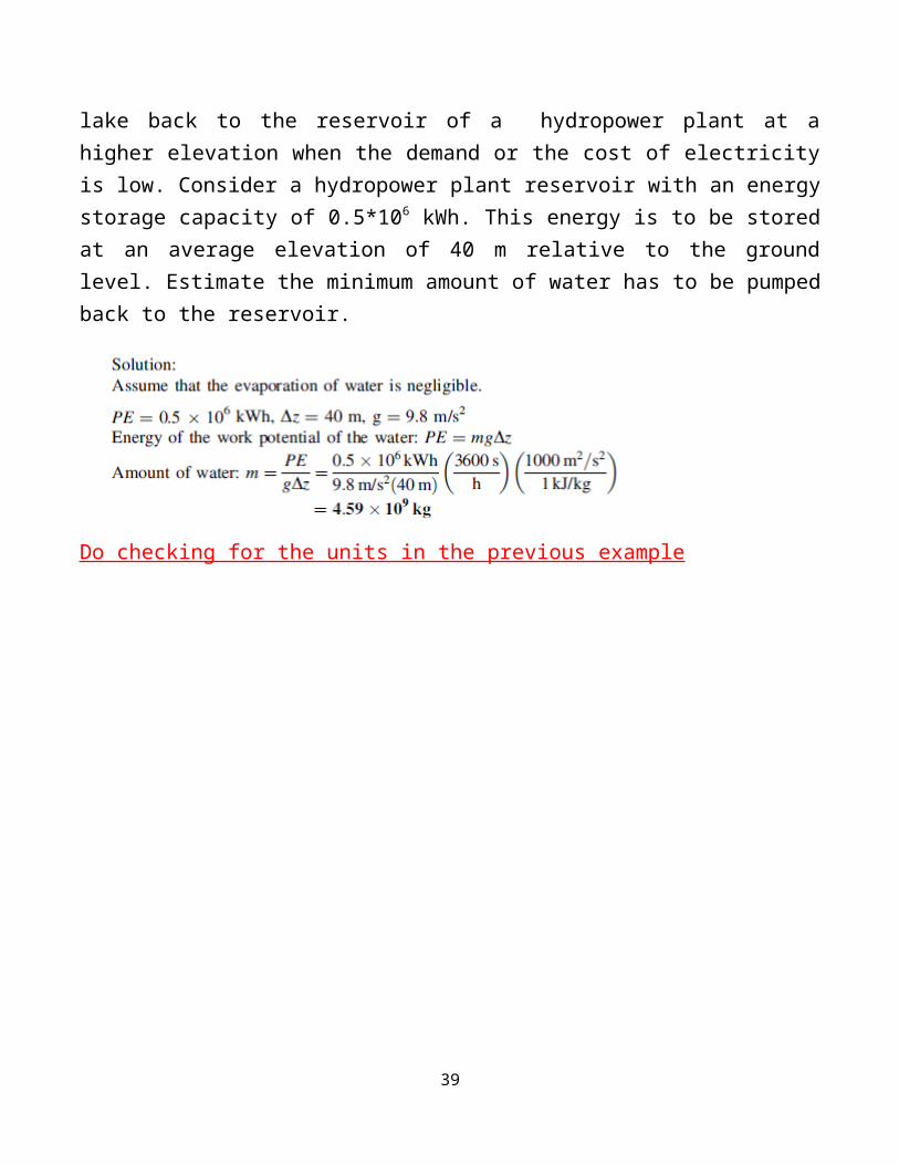
One method of meeting the additional electric power demand at peak usage is to pump some water from a source such as a lake back to the reservoir of a hydropower plant at a higher elevation when the demand or the cost of electricity is low. Consider a hydropower plant reservoir with an energy storage capacity of 0.5*106 kWh. This energy is to be stored at an average elevation of 40 m relative to the ground level. Estimate the minimum amount of water has to be pumped back to the reservoir.
Do checking for the units in the previous example
32

33

THERE ARE THREE CLASSIFICATIONS FOR HYDROPOWER
34

35
There are several advantages of ( SMALL HYDROPOWER )SHP systems that should be considered when
comparing them with other alternatives such as wind and solar energy systems.
• Environmental protection through CO2 emission reduction
• Proven and reliable technology
• Reduces the dependency on imported fuels
• Improves the diversity of energy supply
• Grid Stability
• Reduces land requirements
• Local and regional development
• Good opportunities for technology export
• Assists in the maintenance of river basins
36

• Technology suitable for rural electrification in developing countries
• High energy payback ratio
Main disadvantages of a SHP system are its costs and efficiency. Other issues
include local environmental impacts which should be fully addressed for these
systems before the start of the construction.
Micro-Head Hydropower Systems
The design features of a micro-head hydropower system are basically the same as that of a small hydropower system. Micro-head hydropower systems can utilize a smaller head compared to small hydropower system, and, naturally, produce less power, below 100kW, than small hydropower system. A micro-head hydropower system can operate on a flow rate of 2 gal/min (7.5 cm3/min) and a water head of 2 feet (61 cm) to generate electricity. The voltage generated by this type of system may be sufficient for delivery up to a mile away from the location where it is being used.
A description of a micro-head hydropower system is shown in Fig. 3.41. The factors that should be considered before deciding on a micro-head hydropower system are:
distance from the power source to the location where energy is required, stream
size (including flow rate, output and drop), and other system components, such as
inverter, batteries, controller, transmission line and pipelines.
Problem
Assume that an artificial lake (the base is 20 m above the earth level) was founded to store a quantity of 100 ton of water to be used an energy storage for electricity to be used in the peak period, assume that the lake has a shape looks like a circle with 20 m in diameter, will the height of the water inside the lake affect the generated power significantly? Prove. For a flow rate of 1 l/min, for what period this project will last? Now If an evaporation rate of 10 cc/h.m2 is taken into consideration, will the designed
37

energy be affected for a specified period? If the evaporation rate has a function of 0.1 X 2
where X is the evaporation rate as in above estimate the energy after 7 days of storing water.
Mechanical Energy Storage
Energy may also be stored in pressurized gases or alternatively in a vacuum.
Compressed air, for example, may be used to operate vehicles and power tools.
Large-scale compressed air energy storage (CAES) facilities may be used to supplement demands on electricity generation by providing energy during peak hours and storing energy during off-peak hours. Such systems save on expensive generating capacity since it only needs to meet average consumption
1. Compressed Air Energy Storage
CAES technology stores low cost off-peak energy, in the form of compressed air in
an underground reservoir. The air is then released during peak load hours and
heated with the exhaust heat of a standard combustion turbine. This heated air is
converted into energy through expansion turbines to produce electricity. Energy
storage systems often use large underground caverns due to their very large volume, and thus the large quantity of energy that can be stored with only a small
pressure change. The cavern space can be compressed adiabatically with little
temperature change and heat loss. CAES can also be employed on a smaller scale
such as exploited by air cars and air-driven locomotives. CAES application using
sequestered carbon dioxide is also possible for energy storage. Compression of air generates heat and the air gets warmer. If no extra heat is added, the air will be much colder after decompression, which requires heat. If the heat generated during compression can be stored and used again during decompression, the efficiency of the
38
storage improves considerably. CAES can be achieved in adiabatic, diabatic, or isothermic processes:
• Adiabatic storage retains the heat produced by compression and returns it to the air when the air is expanded to generate power. Heat can be stored in a fluid
such as hot oil (up to 300_C) or molten salt solutions (600_C).
• Diabatic storage dissipates the extra heat with intercoolers (thus approaching
isothermal compression) into the atmosphere as waste. Upon removal from
storage, the air must be reheated prior to expansion in the turbine to power a
generator which can be accomplished with a natural gas-fired burner.
• Isothermal compression and expansion approaches attempt to maintain operating temperature by constant heat exchange to the environment. They are only practical for low power levels and some heat losses are unavoidable. Compression process is not exactly isothermal and some heat losses will occur.
The ideal gas law for an isothermal process is
PV = nRT = constant
WAB = nRT ln(VB/VA)= nRT ln(PA/PB)
where A and B are the initial and final states of the system and W represents the
maximum energy that can be stored or released. In practice, no process is perfectly isothermal and the compressors and motors will have heat losses. Compressed air can transfer power at very high flux rates, which meets the principal acceleration and deceleration objectives of transportation systems, particularly for hybrid vehicles. Examples 8.5 and 8.6 illustrate the simple analysis of mechanical energy storage by compressed air.
39

Example
40

Q.1
Energy Storage in Biofuels
Various biofuels, or biomass can be helpful in reducing the use of hydrocarbon fuels. Some chemical processes, such as Fischer–Tropsch synthesis can convert the carbon and hydrogen in coal, natural gas, biomass, and organic waste into short hydrocarbons suitable as replacements for existing hydrocarbon fuels. Many hydrocarbon fuels have the advantage of being immediately usable in existing engine technology and existing fuel distribution infrastructures. A long-term high oil price may make such synthetic liquid fuels economical on a large-scale production despite some of the energy in the original source being lost in the conversion processes [8]. Carbon dioxide and hydrogen can be converted into methane and other hydrocarbon fuels with the help of energy from another source preferably a renewable energy source. As hydrogen and oxygen are produced in the electrolysis of water,
2H2O = 2H2 + O2
hydrogen would then be reacted with carbon dioxide in producing methane and
water in the Sabatier reaction
CO2 + 4H2 = CH4 + 2H2O
Produced water would be recycled back to the electrolysis stage, give a sketch? reducing the need for new pure water. In the electrolysis stage oxygen would also be stored for methane combustion in a pure oxygen environment (eliminating nitrogen oxides)???.
In the combustion of methane, carbon dioxide and water are produced.
41

CH4 + 2O2 = CO2 + 2H2O
Produced carbon dioxide would be recycled back to the Sabatier process. Methane production, storage, and adjacent combustion would recycle all the reaction products, creating a cycle. Methane is the simplest hydrocarbon with the molecular formula CH4. Methane can be stored more easily than hydrogen and the technologies for transportation, storage, and combustion infrastructure are highly developed. Methane would be stored and used to produce electricity later. Besides that, methanol can also be synthesized from carbon dioxide and hydrogen. If the hydrogen is produced by electrolysis using electricity from wind power, then the electricity is stored by the production of methane or methanol.
HYDROGEN STORAGE AND ECONOMY
One promising alternative to fossil fuels is hydrogen. Hydrogen is the cleanest, sustainable and renewable energy carrier. Although in many ways hydrogen is an attractive replacement for fossil fuels, it does not occur in nature as the fuel H2. Rather, it occurs in chemical compounds like water or hydrocarbons that must be chemically transformed to yield H2. At present, most of the world's hydrogen is produced from natural gas by a process called steam reforming. However, steam reforming does not reduce the use of fossil fuels but rather shifts them from end use to an earlier production step; and it still releases carbon to the environment in the form of CO2. Thus, to achieve the benefits of the hydrogen economy, we must ultimately produce hydrogen from non−fossil resources, such as water, using a renewable energy source. The other methods by which hydrogen produced are electrolysis of water, photochemical method and biochemical methods. The storage of hydrogen becomes the critical problem that the world faces today?? how. Answer ………Developing a high density hydrogen storage system is an essential one, which is above 6.5 wt% and that can release hydrogen at room temperature and atmospheric pressure, has been the focus and the goal of researchers for years.
Hydrogen storage options
42

Because of hydrogen's low density??? State that?, its storage always requires relatively large volumes and is associated with either high pressures (thus requiring heavy vessels) or extremely low temperatures, and/or combination with other materials (much heavier than hydrogen itself).
Large underground hydrogen storage
Underground storage of hydrogen in caverns, aquifers, depleted petroleum and natural gas fields, and human-made caverns resulting from mining and other activities is likely to be technologically and economically feasible. Hydrogen storage systems of the same type and the same energy content will be more expensive by approximately a factor of three than natural gas storage systems, ??why ??due to hydrogen's lower volumetric heating value………what is meant??.
Above-ground pressurized gas storage systems
Hydrogen can be stored in standard pressure cylinders look like gas storage.
Vehicular pressurized hydrogen tanks
Development of ultra-light but strong new composite materials has enabled storage of hydrogen in automobiles. Pressure vessels that allow hydrogen storage at pressures greater than 200 bars have been developed and used in automobiles.
A storage density higher than 0.05 kg of hydrogen per 1 kg of total weight is easily achievable. Storage as liquid H2 imposes severe energy costs because up to 40% of its energy content can be lost to liquefaction. The storage containers lose energy due the boil-off of hydrogen that is caused by thermal conductivity. The boil-off losses vary from 0.06 % per day of large containers to 3 % per day of small vessels. The boil-off losses can be reduced through proper insulation.
Metal Hydrides
43

Metal hydrides are composed of metal atoms that constitute of a host lattice and hydrogen atoms that are trapped in interstitial sites, such as lattice defects such as vacancy. There are two possible ways of hydriding a metal,
direct dissociative chemisorption and electrochemical splitting of water. These reactions are, respectively
M+ x/2 H2=MHx……..1
M+x/2H2O+x/2e=MHx+x/2 OH-
Where M represents the metal. In electrochemical splitting there has to be a catalyst, such as palladium, to break down the water.
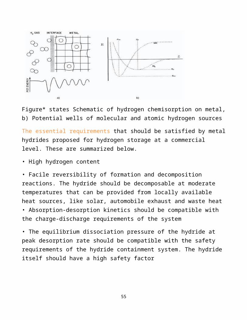
Figure* states Schematic of hydrogen chemisorption on metal, b) Potential wells of molecular and atomic hydrogen sources
The essential requirements that should be satisfied by metal hydrides proposed for hydrogen storage at a commercial level. These are summarized below.
• High hydrogen content
• Facile reversibility of formation and decomposition reactions. The hydride should be decomposable at moderate temperatures that can be provided from locally available heat sources, like solar, automobile exhaust and waste heat • Absorption-desorption kinetics should be compatible with the charge-discharge requirements of the system
44

• The equilibrium dissociation pressure of the hydride at peak desorption rate should be compatible with the safety requirements of the hydride containment system. The hydride itself should have a high safety factor
• The hydride should have a sufficient chemical and dimensional stability to permit its being unchanged over a large number of charge–discharge cycles
• Minimal hysteresis in adsorption–desorption isotherms
• The hydride should be reasonably resistant to deactivation by low concentrations of common (sometimes unavoidable) contaminants such as O2,H2O,CO2, CO, and others
• The total cost of hydride (raw materials, processing and production) should be affordable for the intended application. The long term availability of raw materials (that is, the metal resources), must be ensured. The cost of the hydride system (which includes its containment) per unit of reversibly stored hydrogen should be as low as possible
• The storage vessel and ancillary equipment cost and the fabrication and installation costs should be moderate
• Operating and maintenance costs and purchased energy requirements (that is, energy other than waste energy and energy extracted from the ambient air) per storage cycle should be low.
Hydrogen in Carbon Structures
Hydrogen can be stored into the nanotubes by chemisorption or physisorption. The methods of trapping hydrogen are not known very accurately but density functional calculations have shown some insights into the mechanisms Calculations indicate that hydrogen can be adsorbed at the exterior of the tube wall by H-C bonds with a H/C
254 Hydrogen Storage and Economy
coverage 1.0 or inside the tube by H-H bonds with a coverage up to 2.4 as shown in Figure 7. The adsorption into the interior wall of the tube is also possible but not stable. The hydrogen relaxes inside the tube forming H-H bonds. The numbers in the figure tell the bond lengths in 10-10 m.
45

Chemical Storage
Chemical compounds containing hydrogen can also be considered as a kind of hydrogen storage. These include e.g. methanol CH2OH, ammonia NH3, and methylcyclohexane CH3C6H12. In STP condition all of these compounds are in liquid form and thus the infrastructure for gasoline could be used for transportation and storage of the compounds. This is a clear advantage compared to gaseous hydrogen, which demands leak-proof, preferably seamless, piping and vessels. The hydrogen storage capacity of these chemical compounds is quite good – 8.9 wt% for CH2OH, 15.1 wt% for NH3, and 13.2 wt% for CH3C6H12. These figures do not include the containers in which the liquids are stored. Because the containers can be made of light-weighted composites or even plastic in some cases, the effect of a container is negligible especially with larger systems. Chemical storage of hydrogen has also some disadvantages. The storage method is non-reversible, i.e. the compounds cannot be “charged” with hydrogen reproducibly. The compounds must be produced in a centralized plant and the reaction products have to be recycled som8nbnbbhow. This is difficult especially with ammonia, which produces highly pollutant and environmentally unfavorable nitrogen oxides. Other compounds produce carbon oxides, which are also quite unfavorable.
46

Batteries
Batteries are referred to as electrochemical or galvanic cells, due to the fact that they store electrical energy in the form of chemical energy and because the electrochemical reactions that take place are also termed galvanic. Galvanic reactions are thermodynamically favorable (the free energy difference, Δ G , is negative) and occur spontaneously when two materials of different positive standard reduction potentials are connected by an electronic load (meaning that a voltage is derived). The material with the lower positive standard reduction potential undergoes an oxidation reaction providing electrons by the external circuit to the material with the higher positive standard reduction potential, which in turn undergoes a reduction reaction. These half reactions occur concurrently and allow for the conversion of chemical energy to electrical energy by means of electron transfer through the external circuit. It follows that the material with the lower positive standard reduction potential is called the negative electrode or anode on discharge (since it provides electrons), while the material with the higher positive standard reduction is called the positive electrode or cathode on discharge (since it accepts electrons). In addition to the electrodes, the two other constituents that are required for such reactions to take place are the electrolyte solution and the separator. The electrolyte is an ion conducting material, which can be in the form of an aqueous, molten, or solid solution, while the separator is a membrane that physically prevents a direct contact between the two electrodes and allows ions but not electrons to pass through; it therefore ensures electrical insulation for charge neutralization in both the anode and cathode once the reaction is completed. Two final parts required to complete a commercial galvanic cell are the terminals. They are necessary when applying the batteries to electrical appliances with specific holder designs in order to prevent short - circuit by battery reverse installation, and they are shaped so as to match the receptacle facilities provided in the appliances. For example, in cylindrical batteries, the negative terminal is either designed so as to be flat, or to protrude out of the battery end, while the positive terminal extends as a pip at the opposite end. A simple galvanic cell is illustrated in Figure 1.1 a, while Figure 1.1 b shows terminal designs for cylindrical batteries.
47

Voltage
The theoretical standard cell voltage, E0 (cell) can be determined using the electrochemical series and is given by the difference between the standard electrode potential at the cathode, E 0 (cathode), and the standard electrode potential at the anode, E0 (anode) as
E0 (cathode) −E0 (anode) = E0 (cell)
The standard electrode potential, E0 , for an electrode reaction, written (by convention) as a reduction reaction (i.e., involving consumption of electrons), is the potential generated by that reaction under the condition that the reactants and the products are in their standard state in relation to a reference electrode. In order to obtain a true estimate of the actual open circuit cell voltage in the fully charged state for operation of the battery, the theoretical cell voltage is modified by the Nernst equation, which takes into account the nonstandard state of the reacting component as
E = E0 −RT lnQ (1.2)
48

The Nernstian potential in Eq. (1.2) will change with time due to the self – discharge by which the activity (or concentration) of the electroactive component in the cell is modified. Thus, the nominal voltage is determined by the cell chemistry at any given point of time. The operating voltage produced is further modified as a result of discharge reactions actually taking place and will always be lower than the theoretical voltage due to polarization and the resistance losses ( IR drop) of the battery as the voltage is dependent on the current, I , drawn by an external load and the cell resistance, R , in the path of the current. Polarization rises in order to overcome any
49

activation energy for the electrode reaction and/or concentration gradients near the electrode. These factors are dependent upon electrode kinetics and, thus, vary with temperature, state of charge, and with the age of the cell. Of course the actual voltage appearing at the terminal needs to be sufficient for the intended application.
Tafel Curves for a Battery
In a battery there are two sets of Tafel curves present, one for each electrode material. During discharge one material will act as the anode and the other as the cathode. During charging the roles will be reversed. The actual potential difference between the two electrodes for a given current density can be found from the Tafel curve. The total cell potential is the difference between the anodic potential, Ea , and the cathodic potential, Ec . In a galvanic cell, the actual potential, V cell, discharge , is less than the′ Nernst potential
Vcell,discharge = Ec − ηc +Ea – ηa (1.28)
Upon discharge the cell potential may be further deceased by the ohmic drop due
to the internal resistance of the cell, r . Thus, the actual cell potential is given by
Vcell, discharge =Vcell, discharge – i Ar (1.29)
where A is the geometric area relevant to the internal resistance and i is the cell
current density.
Similarly, on charging the applied potential is greater than the Nernstian potential, and can be calculated by the equation
Vcell, charge = Ec + ηc +Eα + ηa (1.30)
The cell charging potential may now be increased by the ohmic drop
The cell charging potential may now be increased by the ohmic drop, and the final
actual cell charging potential is given by Vcell, charge =Vcell charge + iAr (1.31)
50

In summary, it can be stated that in order to maximize power density, it is important to achieve the most optimum value of cell potential at the lowest overpotentials and internal resistance. Usually at low current densities, overpotential losses arise from an activation energy barrier related to electron transfer reactions, while at a higher current density, the transport of ions becomes rate limiting giving rise to a current limit. Ohmic losses increase with increasing current, and can be further enhanced by the increased formation of insulating phases during the progress of charging. Power is a product of voltage and current; therefore, decreasing the current density by increasing the true surface area can also in principle result in a higher power density. However, unwanted side reactions may also be enhanced.
Capacity
The bar graph of Figure 1.8 shows the difference between the theoretical and
actual capacities in mAh g − 1 for various battery systems. The theoretical molar capacity of a battery is the quantity of electricity involved in the electrochemical reaction. It is denoted as Q charge and is given by
Qcharge = xnF (1.32)
where x is the number of moles of a chosen electroactive component that take
place in the reaction, and n is the number of electrons transferred per mole of
reaction. The mass of the electroactive component can be calculated as
M= xMr (1.33)
where M denotes the mass of the electroactive component in the cell and Mr the
molecular mass of the same component. The capacity is conventionally expressed
as Ah kg − 1 thus given in terms of mass, often called specific capacity, C specific
C specific= nF/Mr 1.34
51

If the specific capacity is multiplied by the mass of the electroactive component
in the cell, one will obtain the rated capacity of a given cell. It is important to note
that the mass may refer to the final battery mass including packaging or it may be reported with respect to the mass of the electroactive components alone. It is quite straightforward to recalculate the capacity in terms of the mass of the cell by dividing the rated capacity with the total mass of the cell.
In practice, the full battery capacity could never be realized, as there is a signifi -
cant mass contribution from nonreactive components such as binders & conducting particles, separators & electrolytes and current collectors and substrates, as well as packaging. Additionally, the chemical reactions cannot be carried out to completion; either due to unavailability of reactive components, inaccessibility of active materials or poor reactivity at the electrode/electrolyte interface. The capacity is strongly dependent upon the load and can decrease rapidly at high drain rates as defined by the magnitude of current drawn, due to increased overpotential losses and ohmic losses which can exacerbate the problems with completion of the reaction. At higher drain rates denoting high operating currents, a battery will be discharged faster.
52

1.2.4
Shelf - Life
A cell may be subject to self discharge in addition to discharge during operation. Self - discharge is caused by parasitic reactions, such as corrosion, that occur even when the cell is not in use. Thus, the chemical energy may slowly decrease with time. Further energy loss may arise as a result of discharge during which insulating products may form or the electrolyte may be consumed. Therefore, shelf – life is limited by factors related to both nonuse and normal usage.
1.2.5
Discharge
Discharge Curve/Cycle Life
The discharge curve is a plot of the voltage against the percentage of the capacity
discharged. A flat discharge curve is desirable as this means that the voltage remains constant as the battery is used up. Some discharge curves are illustrated
in Figure 1.9 , where the potential is plotted against time as the battery is discharged through a fixed load. In the ideal mode, the cell potential remains
steady with time until the capacity is fully exhausted at the same steady rate and
then it falls off to a low level. Some of the primary lithium cells display this type
of nearly ideal flat discharge characteristics. In most other real batteries, the
voltage may slope down gently with time as in primary alkaline cells or do so in
two or more stages during discharge as in Lechlance cells.
53

is limited by factors related to both nonuse and normal usage.
54
55

Specific Energy Density
The specific energy density, Wh/kg, is the energy that can be derived per unit
mass of the cell (or sometimes per unit mass of the active electrode material). It
is the product of the specific capacity and the operating voltage in one full discharge cycle. Both the current and the voltage may vary within a discharge cycle and, therefore, the specific energy, E , derived is calculated by integrating the product of the current and the voltage over time
E = ∫V ⋅I dt (1.35)
The discharge time is related to the maximum and minimum voltage thresholds
and is dependent upon the state of availability of the active materials and/or the
avoidance of an irreversible state for a rechargeable battery. An active component may be less available due to side reactions, such as:
(i) zinc reacting with the electrolyte in alkaline or silver oxide – zinc batteries,
(ii) dendrite formation in rechargeable batteries,
(iii) formation of passivation layers on the active components. Since batteries are used mainly as energy storage devices, the amount of energy (Wh) per unit mass (kg) is the most important property quoted for a battery. It must be noted that the quoted values only apply for the typical rates at which a particular type of battery is discharged. The specific energy density values vary between 45 and 300 Wh/kg for primary batteries and 30 and 240 Wh/kg for secondary (rechargeable) batteries.
Power Density
The power density is the power that can be derived per unit mass of the cell
(W/kg). At higher drains, signifying higher currents relating to higher power
densities, the specific energy tends to fall off rapidly, hence, decreasing the capacity. This trade - off between power and energy density is best expressed in a Ragone plot, an
56

idealized version of which is given in Figure 1.10 . It is obvious that a certain battery has a range of values for specific energy and power, rather than a battery having a specific value of energy and power. In order to derive the maximum amount of energy, the current or the power drain must be at the lowest practical level. For a given cell chemistry, increasing the surface area of the electrodes can increase the cell’s current at a given current density and, thus, deliver more power. The most efficient way to deliver a higher power density is to increase the effective surface area of an electrode while keeping the nominal area constant. It is important to consider any increase in parasitic reactions that may be enhanced due to the increase in the effective surface area. For example, in systems where corrosion is a concern, simply increasing the surface area may enhance the corrosion reactions while depleting the active material. Under these circumstances, the cell capacity will decrease along with the shelf – life.
57