Embed Size (px)
Citation preview

ElectroCity (Grades 4-5)Teacher’s Guide
OverviewThis unit develops concepts of energy and electricity, and culminates in design of circuits controlled by hidden switches. Opening or closing a box or card triggers lights and sounds, and sets color wheels and vibrators in motion. Students first learn to connect lights and buzzers to batteries, and then to control these circuits with homemade switches. To understand and troubleshoot their circuits, they develop strategies for making diagrams using standard symbols that everyone in the class can agree on. Subsequently, they add motors to their circuits. Students use what they have learned to create their own “ElectroCities” – scenes that tell stories using circuits to provide light, sound and motion effects. In common devices such as refrigerators, automatic doors and alarms, switches are often hidden from view. Students create their own hidden switches, which are operated by doing other tasks, such as opening or closing a card or book. Infrared remotes are introduced as ways of operating a switch at a distance. Students also learn to make noisemakers, vibrators, and fluorescent displays. In the final performance task, students design, make and present their culminating projects.
Common Core Learning Standards for ELACommon Core Writing Standards 4-5
Text Types and purposes
2. Write informative/explanatory texts to examine and convey complex ideas and information clearly and accurately through the effective selection, organization and analysis of content.
Production and Distribution of writing
4. Produce clear and coherent writing in which the development, organization, and style are appropriate to task, purpose, and audience.
5. With guidance and support from peers and adults, develop and strengthen writing as needed by planning, revising and editing.
Research to Build and Present Knowledge
7. Conduct short research projects that build knowledge through investigation of different aspects of a topic.
Common Core Speaking and Listening Standards 4-5
Comprehension and Collaboration
1. Engage effectively in a range of collaborative discussions with diverse partners, building on others’ ideas and expressing their own clearly.
Presentation of Knowledge and Ideas
4. Report on a topic, sequencing ideas logically and using appropriate facts and relevant, descriptive details to support main ideas or themes.
Common Core Language Standards 4-5
Vocabulary acquisition and use
4. Demonstrate or clarify the meaning of unknown or multiple-meaning words and phrases, choosing flexibly from a range of strategies.
6. Acquire and use accurately a range of general academic and domain-specific words and phrases.
1

Next Generation Science Standards/ Frameworks for K-12 Science EducationDimension 1: Scientific and Engineering Practices:
1. Asking questions and defining problems: Students should be able to ask questions of each other about the phenomena they observe and the conclusions they draw from their models or scientific investigations. For engineering, they should ask questions to define the problem to be solved and to elicit ideas that lead to the constraints and specifications for its solution.
2. Developing and using models: Students should be asked to use diagrams, maps and other abstract models to as tools that enable them to elaborate on their own ideas, develop explanations and present them to others.
3. Planning and carrying out investigations: In the elementary years, students’ experiences should be structured to help them learn to define the features to be investigated, such as patterns that suggest causal relationships.
4. Analyzing and interpreting data: At the elementary level, students need support to recognize the need to record observations – whether in drawings, words or numbers – and to share them with others.
6. Constructing explanations and designing solutions: The process of developing a design is iterative and systematic, as is the process of developing an explanation in science. Elements that are distinctive in engineering include specifying constraints and criteria for desired qualities of the solution, developing a design plan, producing or testing models or prototypes, selecting among alternative design features, and refining design ideas based on the performance of a prototype.
7. Engaging in argument from evidence: In engineering, reasoning and argument are essential to finding the best possible solution to a problem. At an early design stage, competing ideas must be compared (and possibly combined), and the choices are made through argumentation about the merits of the various ideas pertinent to the design goals.
8. Obtaining, evaluating and communicating information: Students need opportunities to communicate ideas using appropriate combinations of sketches, models and language. They should also create drawings to test concepts and communicate detailed plans; explain and critique models, and present both planning stages and ultimate solutions.
Dimension 2: Crosscutting concepts:
1. Patterns: Noticing patterns is often a first step to organizing and asking scientific questions about why and how the patterns occur. In engineering, it is important to observe and analyze patterns of failure in order to improve a design.
2. Cause and effect: mechanism and prediction: Any application of science, or any engineered solution to a problem, is dependent on understanding the cause-and-effect relationships between events. The process of design is a good place to start, because students must understand the underlying causal relationships in order to devise and explain a design to achieve a specified objective.
3. Scale, proportion and quantity: The concept of scale builds from the early grades as an essential element of understanding phenomena. Young children can begin understanding scale with objects, space and time related to their world and with scale models and maps.
4. Systems and system models: A system is an organized group of related objects or components that form a whole. Models can be valuable in predicting a system’s behaviors or in diagnosing its problems and failures. Students express their thinking with drawings or diagrams and with written or oral descriptions. They should describe objects in terms of their parts and the role those parts play in the functioning of the object.
5. Energy and matter: flows, cycles and conservation: Laws of conservation of matter and energy provide limits on what can occur in a system, whether human-built or natural. The ability to examine, characterize
2

and model the transfers and cycles of matter and energy is a tool that students can use across virtually all areas of science and engineering.
6. Structure and function: The functioning of systems depends on the shapes and relationships of certain key parts, as well as on the properties of the materials. Exploration of the relationship between structure and function can begin in the early grades through investigations of accessible systems in the natural and human-built world.
7. Stability and change: Much of science and mathematics has to do with understanding how change occurs in nature and in social and technological systems, and much of engineering has to do with creating and controlling change.
Dimension 3: Disciplinary Core Ideas – Physical Science:
Core Idea PS2: Motion and Stability: Forces and InteractionsInteractions between any two objects can cause changes in one or both of them. An understanding of the forces between objects is important for describing how their motions change, as well as for predicting stability or instability in systems.
Core Idea PS3: EnergyEnergy cannot be created or destroyed, but it can be transported from one place to another and transferred between systems. Energy manifests itself in multiple phenomena, such as motion, light, sound, electrical and magnetic fields and heat energy.
Core Idea PS4: Waves and their Applications in Technologies for Information Transfer Electromagnetic waves can be detected over a wide range of frequencies, of which the visible spectrum is just a small part. Modern communication systems are based on the use of electromagnetic waves, including light waves, radio waves, microwaves and infrared.
Dimension 3: Disciplinary Core Ideas – Engineering, Technology and Applications of Science
Core Idea ETS1: Engineering DesignIdentification of a problem and the specification of clear design goals, contending with constraints, using models to better understand the features of a design problem, compare designs, test them and compare their strengths and weaknesses. Selection of a design often requires making trade-offs among competing criteria.
Core Idea ETS2: Links among Engineering, Technology and SocietyAdvances in science, engineering and technology have had profound effects on human society, which can change significantly when new technologies are introduced, with both desired effects and unexpected outcomes.
3

Curriculum Map
Lesson Title SummaryApprox.
time (min.)
Vocabulary Homework and Extensions Assessment Methods
1 Light & Sound
Turning on a LED and a buzzer
100 electricity, circuit, battery, light-emitting diode (LED), buzzer, voltage, current, polar, load, energy, energy transformation, input, output, light, sound, switch
HW: Switch Hunt
Extension: Add another battery
Observation, discussion, written work
2 Make a Switch
Creating a switch from paper clips and fasteners
150 switch, push-button switch, rotary switch, slide switch, toggle switch, pull-chain switch, control, contact, connector , insulator, conductor
Extension: Make all four types of switches
Observation, discussion, written work
3 Circuit diagrams
Finding standard ways to represent circuits
100 Symbol, standard, diagram, model, system
Extension: Design a new circuit using a diagram
Homework: Motor hunt
Drawings and diagrams made by students
4 Motors Operating and controlling motors
50 Motor, shaft, battery holder, rotation, , direction, clockwise, counterclockwise, kinetic energy, charge
Extension: Add weight to the motor shaft
Observation, discussion, written work
5 Make a simple ElectroCity!
Making a scene, story or idea come alive with light, sound & motion effects
100 Design, plan, troubleshooting HW: Hidden-switch hunt Observation, student projects
6 Hidden Switches
Finding and making hidden switches
100 Exposed, hidden, manual, automatic Extension: Clothespin switch Observation, discussion, written work
4

Lesson TitleStandards alignment
CCLS -- ELA NGSS – Scientific & Engineering Practices
NGSS – Cross-cutting Concepts
NGSS – Disciplinary Core Ideas
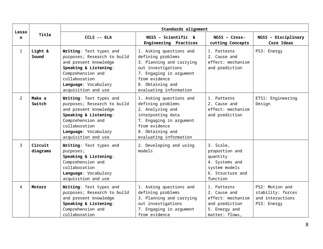
1 Light & Sound Writing: Text types and purposes; Research to build and present knowledgeSpeaking & Listening: Comprehension and collaborationLanguage: Vocabulary acquisition and use
1. Asking questions and defining problems 3. Planning and carrying out investigations 7. Engaging in argument from evidence8. Obtaining and evaluating information
1. Patterns2. Cause and effect: mechanism and prediction
PS3: Energy
2 Make a Switch Writing: Text types and purposes; Research to build and present knowledgeSpeaking & Listening: Comprehension and collaborationLanguage: Vocabulary acquisition and use
1. Asking questions and defining problems 2. Analyzing and interpreting data 7. Engaging in argument from evidence8. Obtaining and evaluating information
1. Patterns2. Cause and effect: mechanism and prediction
ETS1: Engineering Design
3 Circuit diagrams
Writing: Text types and purposes; Speaking & Listening: Comprehension and collaborationLanguage: Vocabulary acquisition and use
2. Developing and using models 3. Scale, proportion and quantity4. Systems and system models6. Structure and function
4 Motors Writing: Text types and purposes; Research to build and present knowledgeSpeaking & Listening: Comprehension and collaborationLanguage: Vocabulary acquisition and use
1. Asking questions and defining problems 3. Planning and carrying out investigations 7. Engaging in argument from evidence8. Obtaining and evaluating information
1. Patterns2. Cause and effect: mechanism and prediction5. Energy and matter: flows, cycles and conservation
PS2: Motion and stability: forces and interactionsPS3: Energy
5 Make a simple ElectroCity!
Speaking & Listening: Presentation of knowledge and ideasLanguage: Vocabulary acquisition and use
4. Systems and system models6. Structure and function
ETS1: Engineering Design
6 Hidden Switches
Writing: Text types and purposes; Research to build and present knowledgeSpeaking & Listening: Comprehension and collaborationLanguage: Vocabulary acquisition and u
1. Asking questions and defining problems 3. Planning and carrying out investigations 4. Systems and system models; 6. Structure and function
PS2: Motion and StabilityETS1: Engineering Design
5

Lesson Title SummaryApprox.
time (min.)
Vocabulary Homework and Extensions Assessment Methods
7 Shakers & Noisemakers
Using circuits to make things vibrate and/or make noise
100 Vibrate, shake, balanced, unbalanced, noise, sound, volume, softer ,louder, pitch, higher pitch, lower pitch
Extension: Control a noisemaker or a shaker with a hidden switch
Observation, discussion, written work
8 Things that Glow in the Dark
Creating fluorescent displays that glow in the dark
50 Light, spectrum, visible, ultraviolet, fluorescent
Extension: Make a light box with a secret message
Observation, discussion, written work
9 Infrared Remotes
Controlling a circuit from a distance
100 Communication, transmitter, receiver, phototransistor, signal, remote, infrared, incandescent, fluorescent
Extension: Experiments with Infrared remotes
Observation, discussion, written work
10 Design an ElectroFying ElectroCity
Designing a mystery box or card with a surprise element, controlled by a hidden switch
50 Extension: Series and parallel circuits
Observation, student projects
11 Make an ElectroFying ElectroCity
Creating and troubleshooting the automatic ElectroCity
150 Esthetic design, complex system, subsystem, structure
Extension: Using a Digital Multimeter
Observation, student projects
12 Present your ElectroCity
Presenting projects to an audience
50 Student presentations
6

Lesson TitleStandards alignment
CCLS -- ELA NGSS – Sci. & Engr Practices NGSS – Cross-cutting Concepts
NGSS – Disciplinary Core Ideas
7 Shakers & Noisemakers
Writing: Text types and purposes; Research to build and present knowledgeSpeaking & Listening: Comprehension and collaborationLanguage: Vocabulary acquisition and use
1. Asking questions and defining problems 3. Planning and carrying out investigations 7. Engaging in argument from evidence8. Obtaining and evaluating information
1. Patterns2. Cause and effect: mechanism and prediction5. Energy and matter: flows, cycles and conservation
PS2: Motion and stability: forces and interactionsPS3: Energy
8 Things that Glow in the Dark
Writing: Text types and purposes; Research to build and present knowledgeSpeaking & Listening: Comprehension and collaborationLanguage: Vocabulary acquisition and use
1. Asking questions and defining problems 3. Planning and carrying out investigations 7. Engaging in argument from evidence8. Obtaining and evaluating information
1. Patterns2. Cause and effect: mechanism and prediction5. Energy and matter: flows, cycles and conservation
PS3: EnergyPS4: Waves and their Applications in Technologies for Information Transfer
9 Infrared Remotes
Writing: Text types and purposes; Research to build and present knowledgeSpeaking & Listening: Comprehension and collaborationLanguage: Vocabulary acquisition and use
1. Asking questions and defining problems 3. Planning and carrying out investigations 7. Engaging in argument from evidence8. Obtaining and evaluating information
1. Patterns2. Cause and effect: mechanism and prediction5. Energy and matter: flows, cycles and conservation
PS3: Energy PS4: Waves and their Applications in Technologies for Information TransferETS2: Links among engineering, technology and society
10 Design an ElectroFying ElectroCity
Speaking & Listening: Presentation of knowledge and ideasLanguage: Vocabulary acquisition and use
1. Asking questions and defining problems 3. Planning and carrying out investigations
2. Cause and effect: mechanism and prediction6. Structure and function
ETS1: Engineering Design
11 Make an ElectroFying ElectroCity
Speaking & Listening: Presentation of knowledge and ideasLanguage: Vocabulary acquisition and use
3. Planning and carrying out investigations
2. Cause and effect: mechanism and prediction4. Systems and system models6. Structure and function
ETS1: Engineering Design
12 Present your ElectroCity
Speaking & Listening: Presentation of knowledge and ideasLanguage: Vocabulary acquisition and use
3. Planning and carrying out investigations
2. Cause and effect: mechanism and prediction6. Structure and function
ETS1: Engineering Design
7
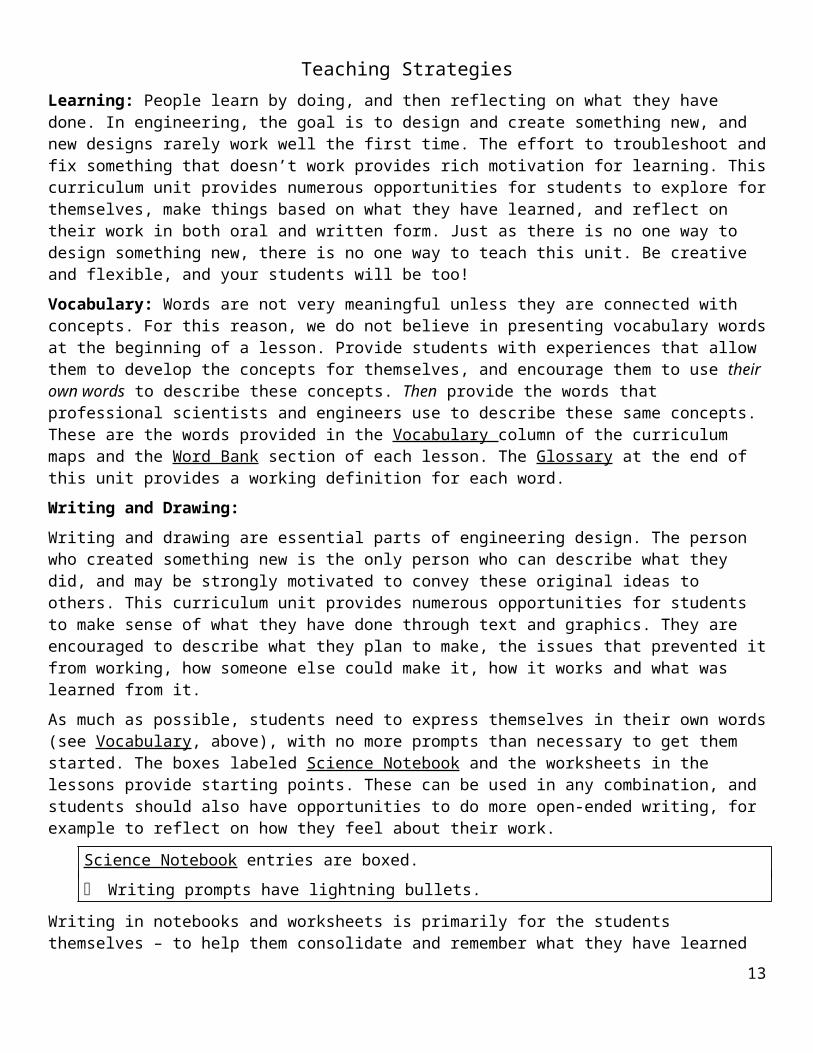
Teaching StrategiesLearning: People learn by doing, and then reflecting on what they have done. In engineering, the goal is to design and create something new, and new designs rarely work well the first time. The effort to troubleshoot and fix something that doesn’t work provides rich motivation for learning. This curriculum unit provides numerous opportunities for students to explore for themselves, make things based on what they have learned, and reflect on their work in both oral and written form. Just as there is no one way to design something new, there is no one way to teach this unit. Be creative and flexible, and your students will be too!
Vocabulary: Words are not very meaningful unless they are connected with concepts. For this reason, we do not believe in presenting vocabulary words at the beginning of a lesson. Provide students with experiences that allow them to develop the concepts for themselves, and encourage them to use their own words to describe these concepts. Then provide the words that professional scientists and engineers use to describe these same concepts. These are the words provided in the Vocabulary column of the curriculum maps and the Word Bank section of each lesson. The Glossary at the end of this unit provides a working definition for each word.
Writing and Drawing:
Writing and drawing are essential parts of engineering design. The person who created something new is the only person who can describe what they did, and may be strongly motivated to convey these original ideas to others. This curriculum unit provides numerous opportunities for students to make sense of what they have done through text and graphics. They are encouraged to describe what they plan to make, the issues that prevented it from working, how someone else could make it, how it works and what was learned from it.
As much as possible, students need to express themselves in their own words (see Vocabulary, above), with no more prompts than necessary to get them started. The boxes labeled Science Notebook and the worksheets in the lessons provide starting points. These can be used in any combination, and students should also have opportunities to do more open-ended writing, for example to reflect on how they feel about their work.
Science Notebook entries are boxed.
Writing prompts have lightning bullets.
Writing in notebooks and worksheets is primarily for the students themselves – to help them consolidate and remember what they have learned and communicate it to others – but it also serves as an assessment tool. It should not be marked closely for grammar and spelling. However, it is appropriate to ask students to read what they have written to the class, and to challenge them to clarify ideas that are unclear or incomplete. Much of the description will require drawings or diagrams as well as text, and it is important to help students learn to coordinate these two modes of communication.
Discussion:
Speaking and listening are essential forms of literacy and are central to learning science and engineering. The purpose of a discussion, like that of writing and drawing, is to create meaning. A discussion is not a question-and-answer session led by the teacher, nor a sharing session in which students simply report on what they did. Making meaning requires that students listen and respond to one another’s ideas. In a discussion of engineering design, students may want to bring up issues that they have encountered. Other students may respond by identifying similar issues, and/or by suggesting solutions that they have come up with. As the teacher, your role is to facilitate this give-and-take, by posing questions for discussion and then maintaining focus within the group. Sample focusing questions are identified like this within each lesson:
Lightning bullets and italics indicate prompts for discussion
Reference: Worth, K., Winokur, J. Crissman, S., Heller-Winokur, M. (2009) The Essentials of Science and Literacy: A Guide for Teachers. Portsmouth, NH: Heinemann.
8

Structure of the Lesson PlansThe following categories appear in each lesson (*), or most lessons (**):
*Essential Question
*Task
*Standards
*Outcomes
*Assessment
**Advance Preparation
*Materials
*Procedure
**Word bank
**Homework
**Extensions
**Worksheets
Overview of Basic conceptsEnergy is needed to make things happen, such as getting something to move, light up, vibrate or make noise. Energy can take many forms. Types include energy of sound, light, heat, position and motion; as well as elastic, chemical, magnetic and electrical energy. Energy can’t be created or destroyed, but it can be changed from one form to another. A battery stores energy in chemical form. Whenever the battery is part of a complete circuit, some of this energy changes to electrical energy. Electric energy is versatile, because it can be converted to many other forms. For example, a motor changes electric energy to kinetic energy; a lamp changes it to light energy, and a buzzer or speaker changes it to sound energy. You can’t see or hear electric energy at work, until it changes to light or sound. Anything that changes electrical energy to some other form is called a load. Motors, lamps, buzzers, speakers, and toasters are all examples of loads. The opposite of a load is a source: it changes energy from some other form into electrical energy. Examples of sources are generators, solar cells and batteries.
A circuit is a system that includes a source, a load and conductors that transfer electrical energy from one to the other and back again. Systems can be difficult to understand, because they involve pieces or subsystems that interact to function together. To make a system easier to understand, it is useful to construct a model that shows the way the parts interact without confusing details. A type of model that can represent a circuit is a circuit diagram, which uses standard symbols and connection rules to make the structure clear. A circuit diagram can be very helpful for troubleshooting or explaining a circuit, or for designing a new one.
A control governs the flow of energy. Examples of a control are a faucet, the knob on a stove that controls the flow of gas, or the button on an umbrella that releases the spring, allowing the umbrella to pop open. A control that governs the flow of electricity in a circuit is called a switch. Nearly every circuit has a switch of some kind, so that it is not always ON. Some switches are manual – a person turns them ON or OFF intentionally – while others are hidden or automatic, because they are operated by some other action. An ordinary light switch, push button and pull-chain are examples of manual switches. Automatic switches are found in alarms, voice-operated devices, refrigerators, car doors and “tickle-me” toys.
9

Teacher Notes on the LessonsLesson 1: Light and Sound
Coin batteries, buzzers and LEDs: The battery has a larger flat side and a slightly smaller flat side. The large flat side is the positive (+) side – it has some writing and a “+” engraved into it. The smaller flat side is the “—“ side. LED stands for light-emitting diode. A diode is an electronic component that can pass current in only one direction – kind of like a one-way valve or “exit only” for electrons, and therefore, electric current. The LED has a long wire and a short wire. It will not light up unless the long wire is touching the “+” side of the battery, and the short wire is touching the “—“ side, and the two wires are not touching each other. With an ordinary light bulb, you could reverse the direction, and the bulb would still light up. Because the LED allows current to flow only one way, reversing the wires will not work. A device that be connected only one way is called polar. The buzzer is polar too. To make it work, the red wire has to touch the “+” side of the battery, and the black wire has to touch the “—“ side. If the wires are reversed, it will not work.
Electric circuit model: Electricity is carried by tiny invisible particles called electrons. Two basic measures of electricity are current and voltage. The amount of current counts the rate at which the electrons are flowing. In the Penguin RaceTM toy, the penguins are like the electrons. To increase the current, you would have to add penguins. Voltage is a measure of how much energy kick the battery gives each electron as it passes through. The analogy to the battery in the toy model is the escalator. More voltage would correspond to a taller escalator, which would raise the penguins higher, and therefore give them more energy each time they went around the loop. The penguins obviously have to make a complete circuit, because otherwise they wouldn’t get back to the escalator to get another energy boost. Similarly, the electrons in a circuit have to return to the battery to get the boost they will need to keep lighting the LED or sounding the buzzer. To illustrate why you need two wires connecting the battery to the buzzer or load, disconnect the bottom of the ramp, where it should connect to the escalator. Breaking the circuit prevents the penguins from getting back to the escalator. In the same way, disconnecting one of the wires from the load (LED or buzzer) breaks the electric circuit, and prevents the electrons from going though the battery and back to the load.
More than one load: To make two LEDs light up from the same battery, both LEDs need to be connected to the battery at the same time. The long wire of each LED should connect to the “+” contact of the battery and the short wire of each one should go to the “—“ side of the same battery. As circuits become more complex, the LED wires can get bent, so it is hard to know which one is long and which was short. To keep track, it is helpful to mark the (+) lead with a little piece of tape.
Only certain combinations will work. The red and yellow LEDs, will come on together, as will the green and blue LEDs, but if you try to mix and match, the red or yellow one will “steal” the current from the blue or green one. The reason is that the red and yellow LEDs come on at a lower voltage than the blue and green ones. Once the red or yellow LED comes on, it won’t allow the voltage to reach the point that will turn the green or blue one on. The buzzer will work with any of the LEDs.
Add another battery: The blue and green LEDs should light up more brightly from two batteries instead of one, while, there should be no change in the brightness of the red or yellow LEDs. Also, the buzzer should become louder when it is attached to two batteries, compared with one. If these results do not occur, check to see that the batteries are connected as shown in the diagram, — to +, as shown in the diagram:
10

Lesson 2: Make a Switch
What is a switch? A switch is a device that can turn the flow of electrical current ON or OFF. It is an example of a control, which is a more general category of devices that can interrupt or allow the flow of energy, not necessarily electrical. Examples of controls are a water faucet, toilet handle, drain plug, stove control knob, mouse trap trigger and the umbrella release button. If a circuit didn’t have a switch, it would be like a sink without a faucet – either on or off all the time.
Conductors and insulators: Some materials allow electricity to flow, while others don’t. Those that do allow flow are called conductors and those that don’t are insulators. All metals are conductors, and nearly all other materials -- such as plastic, paper, cloth and cardboard -- are insulators.
What a switch needs: The basic requirements of a switch are two contacts, a way of attaching or detaching them and a connection to each contact that puts the switch inside the circuit. Both contacts and the connections to them have to be made of conductors, or current won’t flow through them. The switch has to interrupt the circuit when it is OFF, and connect the battery to the load (LED or buzzer) when it is ON. When the switch interrupts the circuit, the circuit is open and no current can flow. When the switch connects the circuit, it is closed, allowing current to flow.
Ideas for making sample switches:
Type Materials How to make it
Push-button
Two paper fasteners, cardstock or cardboard
Attach the fasteners so that the leg of one can be pushed down to touch the head of the other, and so this same leg will spring back up when released.
Rotary
Two paper fasteners, cardstock or cardboard
Push both fasteners through the cardstock, about and inch apart. Keep one leg of one fastener on top. Rotate this leg so it is touching the top of the other fastener to turn the circuit on, and away to turn it off.
Slide Three paper fasteners, cardstock or cardboard
Cut a slot for one paper fastener, and poke holes for the other two. Mount two paper fasteners through the holes with heads up, and mount the third though the slot with both legs up. The legs turn the circuit ON by touching the two heads, and OFF by sliding away from them.
Toggle
Bulldog clip, two paper fasteners, cardstock or cardboard
Mount the paper fasteners about a half inch apart, and place the bulldog clip so its handle can touch both fasteners. Use the snap action of the bulldog clip handle turn the circuit ON and OFF.
11

Troubleshooting circuits with switches
The diagram below shows a simple circuit with a battery, LED and a push button switch; and three connections between them, labeled A, B and C.
A = switch contact attached to (+) side of the batteryB = (+) LED wire attached to other switch contact C = (-) LED wire attached to (-) side of battery
A
C
B
Key
LED
Switch
Battery
If the circuit is attached as shown in the diagram, and the LED doesn’t come on when the switch is closed, there are five possible causes for the trouble. The table below shows how to test for each one, and how to fix it:
Cause Test Fix
Battery or LED is bad
Attach LED directly to battery; if LED still won’t turn on, either LED or battery is bad.
Try a new battery. If LED now comes on, old battery was bad. If LED still doesn’t turn on, replace it.
Bad connection at A, B or C
Squeeze each connection in turn. If switch now operates LED, the connection you were squeezing was bad.
Redo connection, making sure metal is touching metal.
Short circuits
A “short circuit” is a conductor that connects two points that do not appear to be connected, and should not be. There are two common types of short circuits. The most serious type involves a switch that is connected across the battery, as in the drawing below, left. The two dashed lines show the wires that are reversed, compared with the correct circuit, which is shown both above and below. This circuit looks similar to the circuit shown above, and it even appears to work, but it has a basic flaw!
Switch short circuits battery when closed
The switch appears to control the LED, because pushing it down will turn the LED off, and releasing it will turn the LED ON. However, this is the reverse of the way the switch should work. The problem is that the switch is actually ON when the LED goes off, and vice versa. When the switch is closed, current flows from one side of the battery to the other with nothing in between. The current bypasses the LED completely, because the current follows the path of least resistance. When the switch is open, it allows the battery to supply the LED normally. If the switch is left closed for very long, the battery will first get warm and then soon go dead.
SAFETY NOTE: A short circuit across a battery can result in wires getting hot, and potentially causing a minor burn. If anything in a circuit gets warm or hot, disconnect it from the battery immediately. Find the short circuit, and remove it before reconnecting to the battery.
12
Another type of short circuit can occur within a switch. In this case, a switch that appears to be open is actually never open due to the short circuit, because the two metal contacts are always touching, even when they don’t seem to be. The drawing below shows one way this can happen. The rotary switch appears to be open until you look underneath. The two paper fasteners are actually touching! Fortunately, the solution is very simple – just turn the legs a little, so they no longer touch.
The table below summarizes the kinds of things that can go wrong in a circuit with a switch, and what to do about each one:
Issue Cause Fix
Load never turns ON Load or battery is bad Replace load or battery
At least one connections is bad Re-do connection, and secure with tape or rubber band
Load never turns OFF Switch has short circuit Separate contacts so they don’t touch
Load turns on when switch is OFF, and vice versa; battery gets warm
Switch is connected across battery, and can’t interrupt circuit
Rewire circuit so switch can interrupt current path
13

Lesson 3: Circuit diagrams
Using diagrams for troubleshooting circuits
Besides being useful for designing new circuits, the diagrams are also useful for troubleshooting. If time is available for a student to make any of the circuits he or she has designed in part 5, the diagram can be used to troubleshoot the circuit. If the circuit doesn’t work, compare the diagram with the circuit to make sure that:
every line on the diagram corresponds to a connection in the real circuit,
that every symbol on the diagram corresponds to the real component in the circuit, and
nothing is in the circuit that isn’t in the diagram.
A good way to do this is to use a color code. Mark each connection on the diagram in a different color. Then use the same color marker to label the actual connection on the circuit. If each color represents the same connection on both the circuit and the diagram, then the diagram represents the circuit accurately.
If the circuit and diagram correspond, and the circuit still doesn’t work, there are only two possibilities. Either:
some of the connections are not being made (most likely), or
one or more of the components is bad.
You can test the connections by squeezing them or redoing them. Test a battery by connecting it directly to a load that you know is working, and test a load by connecting directly to a battery that you know is good.
Making a circuit that looks like its diagram
If students have difficulty translating between diagrams and circuits, here is an idea that might help. Make a circuit and its diagram, and then tape the components and wires of the circuit down in the same way as the diagram shows them. The correspondence between the circuit and the diagram should be obvious when these are put side-by-side. Then remove the tape, being careful not to undo any of the connections. Does the circuit work any differently? If not, shouldn’t the same diagram still apply?
Using a diagram to discover that a circuit is not designed correctly
Here is an example from Lesson 2. The circuit on the left does not work correctly, because the LED turns ON when the switch is OPEN and OFF when the switch is CLOSED. The circuit on the right works correctly. Using the diagrams, it is not hard to see why.
14

Circuit diagrams for the Extension Activities
A circuit that has both a LED and a buzzer and a switch that controls both together.
A circuit that has both a LED and a buzzer, a switch that controls both together and a separate switch for each one.
A circuit that has both a LED and a buzzer and a separate switch for each one, but no switch that controls both.
15

Lesson 4: Motors
Reversing the connections between the motor and the battery
When you reverse the way the motor is attached to the battery (red to “—“ instead of red to “+”), the motor will turn in the opposite direction. It can be hard to see which way the motor is turning, so it is helpful to add a little piece of tape (or better yet, a feather) to the shaft. The direction it is rotating – clockwise or counterclockwise – should be apparent from watching closely as it just begins to turn, or as it is stopping. Whether it is going clockwise or counterclockwise depends on your point of view. Clockwise viewed from one end is counterclockwise viewed from the other end.
Making a holder for a AA battery
c) Press battery in between paper fasteners, making sure each fastener contacts one battery terminal
b) Push one fastener through each mark on cardstock
a) Mark positions on cardstock for 2 holes, about 1¾” apart
-- piece of cardstock, at least 2" x 3"-- AA battery-- two large paper fasteners (1½” or 2″)-- tape and/or rubber band
Materials
d) Use rubber band or tape to secure battery to paper fasteners
e) Wrap wires around exposed legs of paper fasteners or slip wire between fastener legs. Make sure connection is secure.
16

Lesson 5: Make a Simple ElectroCity!
Coming up with an idea for an ElectroCity
When students begin designing their ElectroCities, encourage them to be creative. They will likely come up with some very good ideas. If some students are having difficulty in thinking of ideas, here are some suggestions:
a) Show students an ElectroCity you or previous students have made;
b) Share the examples listed below;
c) Conduct a class brainstorming session, in which students share their ideas;
d) Connect the ElectroCities to a current class theme.
In brainstorming, there are no bad ideas, and nobody is committed to pursuing any idea they come up with, so it should be a risk-free environment. The point of brainstorming is for students to get ideas from one another. Here are some ideas students have come up with in the past:
A car, with a horn you can turn on or off with a switch.
The night sky, with LEDs representing stars.
A fireworks display.
Fireflies.
A thunderstorm, with the buzzer as thunder and LEDs representing lightning.
An airplane or helicopter, with a motor operating the propeller.
An intersection, using LEDs for the traffic light, and a buzzer for traffic sounds.
Getting a circuit to work
The Teacher Notes for Lessons 1-4 provide numerous examples and suggestions about how to get a circuit to work. Here is a summary of what to look for and what to do. If a circuit doesn’t work, there are three possible explanations:
One of more of the connections is bad.
One or more of the components is bad.
The circuit was not designed properly.
Most circuit problems will probably be due to bad connections. A quick way to test a connection is to squeeze it – if it comes on when squeezed, it needs to be tightened, so the wires and terminals are making good contact. Another way to test for a bad connection is to run a separate wire that makes good contact. If the circuit now operates, the original connection was bad. See Teacher Notes sections for Lessons 1 & 2.
The next possibility is that some of the components are bad. One way to test a component is to substitute another of the same component at the same point in the circuit. If the new one works, but the old one didn’t, and they are both connected the same way, the original component was probably bad. The digital multimeter is also very useful for troubleshooting. See the Appendix.
If the connections are all in place, and the circuit still doesn’t work as it should, the fault may be in the wiring configuration. Use the schematic as a troubleshooting tool to make sure each connection that appears on the schematic is also in place in the actual circuit, and that no extra connections are made that do not appear on the schematic.
17

Lesson 6: Hidden Switches
Hidden switch hunt
Here are some examples that students may not have come up with:
Touch- or motion-activated lights in light-up sneakers and pens.
An electric pencil sharpener switch has a switch inside that is activated by putting a pencil (or any other object that fits) into the hole.
An automobile dome light is controlled by opening or closing any of the doors – similar to a refrigerator or oven light.
An automatic door that opens when someone comes nearby.
Automatic faucets, soap dispensers, toilets and hand dryers in public bathrooms.
A voice-activated toy has a switch inside that responds to noise.
“Tickle-me” toys have switches inside that are activated by pressure.
A car alarm has a hidden switch that turns on when somebody touches the car.
Burglar alarms are activated by opening or breaking a window.
Automatic street lights come on when it gets dark. They have hidden switches that turn on when there isn’t enough light.
Energy savers turn the lights off when there isn’t any motion in the room.
Ideas for Sample Hidden Switches:
1. Switches activated by opening or closing a card
(a) contacts touch when book is closed
(b) contacts touch when book is open
18

2. Switches activated by opening or closing a box:
(a) Load turns on when box is closed
(+) connection to load
fastener
(-) connection to load
AA
+
-
(b) Load turns on when box is open
fastener
(-) connection to load
AA
+
-
(+) connection to load
3. Clothespin Switch:
19

Ideas for gadgets
Here are some ideas students and teachers have come up with:
A dollar bill theft alarm, based on clothespin switch (remove the dollar bill from between jaws of a clothespin, and an alarm sounds)
Cabinet alarm (same as dollar-bill alarm, except that cabinet door pulls a piece of cardstock from between contacts when door is opened)
Upside-down alarm (turn the box upside down, and an alarm sounds)
Wind alarm (alarm sounds when one contact is blown against another)
Light box (close the box and see the light come on through the peephole
“Squeeze-me” toy (alarm sounds when you squeeze in the right place)
Airplane or helicopter (close the lid of the box and the propeller starts turning)
Car (lean back on the seat and the horn blows)
Color wheel (open the box and the wheel spins; sections of colored paper, such as blue and red, blend when the motor is turning)
20

Lesson 7: Shakers and Noisemakers
Shakers
Vibration occurs whenever a rotating disk is unbalanced. You can make a rotating wheel vibrate simply by taping a weight off-center. Any weight at all will work: a coin, paper clip, bead, button, etc. There are two ways to increase the amount of vibration:
Add more weight, or
Move the weight further from the center.
Noisemakers
Almost anything that hits a barrier suddenly will make a noise. Here are some other ideas for making a noisemaker:
a flap could hit a suspended string or rubber band instead of the side of the box,
there could be a bead at the end of the flap,
the motor could rotate a tube with beads inside, etc.
Of course, the motor has to keep turning, so the flap attached to the wheel has to be soft enough that it can continue to rotate, but hard enough to make an audible noise. If the motor won’t turn, two solutions are to:
Move the wheel and flap further from the obstacle; or
Use a more flexible material for the flap.
If the sound isn’t loud enough, the possible remedies are exactly the opposite:
Move the wheel and flap closer to the obstacle; or
Use a more rigid material for the flap. Getting the right balance usually requires some trial-and-error.
To make a lower pitch, put the motor inside a box, and close the box, so the sound reverberates inside the box.
21

Lesson 8: Things that Glow in the Dark
Background information
Ultraviolet light, sometimes called “black light,” is not visible, but has visible effects, such as sunburn. An Ultraviolet (UV) LED works like an ordinary LED, except that most of the light it produces is in the Ultraviolet range, and is therefore not visible. Ultraviolet, infrared, visible light, microwaves, radio waves and X-rays are all forms of radiation. Visible light consists of the familiar colors of the rainbow: red, orange, yellow, green blue and violet. These are different from each other in a property called wavelength, which is a tiny distance that is too small to see. Radiation that is beyond violet is called ultraviolet, and the form that is below red is called infrared. Humans can only see visible light, but some animals can see infrared or ultraviolet as well. Even though we can’t see them, they all affect us. Ultraviolet light from the sun produces sunburn. Ultraviolet light also causes fluorescent materials to glow, which is the principle behind this Lesson. Infrared radiation from the sun or a radiator makes us feel warm, even though we are not touching either one directly. Infrared light is used by most remote controllers, which we will explore in the next lesson. Other kinds of radiation with different wavelengths are called microwaves, radio waves, and X-rays and gamma rays, which are emitted by some radioactive materials.
Troubleshooting common issues
If the message or image isn’t very bright, students are probably using only one coin battery – the UV LED glows much more brightly when connected to two batteries.
If the UV LED doesn’t come on at all , either the two batteries are not connected to the UV LED in series, or the LED is connected backwards. See diagram below:
(long wire)
UV
+
+
+
Any other connection method won’t work.
Background color
The effect changes with the color of the paper. The paper colors that seem to work best are blue, green or brown. Yellow and green paper have the advantage that the highlighter is nearly invisible until the UV light is turned on. Blue and brown provide better contrast, giving the mark an eerie glow in UV light. Red paper does not seem to work at all.
22

Lesson 9: Infrared Remotes
Communication systems
Communication takes place when information travels over a distance. Every communication system consists of a transmitter, which sends the information, a receiver, which accepts it, and some form of signal, which travels between the transmitter and receiver. Ask students for examples of communication systems, and have them identify the transmitter, receiver and form of signal in each one. Here are some possible examples:
Isolating the problem
The receiver/transmitter circuits can be a little hard to troubleshoot, because both have to be working for the red LED to come on. If the transmitter/receiver pair doesn’t work, begin by testing each one separately.
To test the transmitter, try other ways of detecting whether or not it is on:
Turn it on in a dark place. The IR LED should produce a faint red glow.
Turn it on in front of a cell phone camera, the cheaper the better. If the camera has no IR filter, you should see a much brighter light on the screen than you see from the transmitter directly.
To test the receiver, try other sources of IR light, as described in the second Extension:
The sun
Light from an incandescent bulb, such as the one in an ordinary flashlight
A TV or DVD remote controller
Troubleshooting the transmitter
Begin by checking the polarity of transmitter. The short wire of both the transmitter is the (+) side. It is easy to get this wrong, because it is the opposite from all the other LEDs. If the polarity is correct, and the transmitter still doesn’t work, the battery is dead or the LED is dead.
Troubleshooting the receiver
The most common problem is incorrect wiring. Follow the circuit diagram, and make sure each component and connection is in place in the actual circuit. Again, the short wire from the receiver is (+), unlike with other components. Use a color code to make sure each component and connection is there (see Troubleshooting, Lesson 3). Make sure:
There are two coin batteries, arranged in series, (+) side of one to (–) side of the other;
The short wire from the receiver is attached to the exposed (+) side of one coin battery;
The long wires from the receiver and red LED are connected;
The short wire from the RED LED attaches to the exposed (–) side of the other coin battery.
If the receiver still doesn’t work, one of the components – probably a coin battery – must be bad.
Troubleshooting the transmitter/receiver pair
If you have gotten both the receiver and transmitter to work separately, they should work as a pair. Place the receiver close to the transmitter and line them up so they are head to head. Then move them slowly apart.
23

Extensions
1. Seeing the IR transmitter: Try more than one cell phone camera. On more expensive cell phones, the transmitter may be barely visible, while others may show a really bright light. See a video at http://citytechnology.org/node/1934 for more information.
2. Other sources of IR light: This experiment should reveal that incandescent bulbs produce large amounts of infrared, while fluorescent lights and LEDs produce hardly any. This is the reason why incandescent bulbs get hot while the other types run cool. It is also why LEDs and fluorescent lights are much more energy efficient than incandescent lights: most of the energy input to an incandescent bulb is wasted as heat, while nearly all the energy supplied to an LED or fluorescent comes out as light.
3. Turning on a buzzer: Both the black and red wires from buzzer need to be stripped at the ends so that more of the metal is showing. Then wrap the metal wire from the red end around the long wire from the IR receiver, tape the short wire from the IR receiver to the flat (+) terminal of the coin battery, and tape the metal wire from the black end of the buzzer to the (–) side of the battery.
4. Obstacles: IR light will pass through most materials that are transparent to visible light, such as glass, clear plastic and cellophane. IR will be blocked by things that are opaque to visible light, such as cardboard, a hand or a piece of wood or metal. Whether something is transparent or opaque is similar to the issue of whether or not it is a conductor or insulator of electricity. See http://citytechnology.org/node/1938 for more information.
5. Mirrors: Most of the same things that reflect visible light will also reflect infrared. Try aluminum foil or a mirror. The tricky part is lining up the transmitter and receiver, so they can “see” each other. Further information, including a video, is available at http://citytechnology.org/node/1939 .
6. Range of the transmitter: The range is not very much – typically an inch or two. Most of the problem is the alignment between the transmitter and receiver. As suggested in the extension, use a straw to guarantee alignment and thereby increase the range. For more information, go to http://citytechnology.org/node/1940
7. Using a spherical mirror: A way to improve the alignment without using a straw is to use a spherical mirror. This works remarkably well. You can learn more about his idea at http://citytechnology.org/node/1937. This is the same strategy that satellite TV companies use. A spherical mirror is similar to a parabolic mirror, which has a special shape that focuses the rays. A satellite dish surrounds the TV antenna with a parabolic reflector that brings the TV signal into the receiver, even though it is not aligned well. Automobile headlights use a similar strategy, but in reverse. They surround a small light with a parabolic mirror that spreads the light out so it looks much bigger than it really is.
24

Lesson 10: Design an Electrofying ElectroCity
Ideas for ElectroFying ElectroCities
Buzz box : This is a box that buzzes when you close it. In addition to the buzzer, there could be a motor in the box with an off-center wheel, causing the box to vibrate as well as buzz.
Color mixer: The idea is to make a rotating wheel with different colors of cardstock attached. Use the color wheel to explore
Jitterbug : Make a shaker, as in Lesson 7, and attach it to a cardboard base. Support the base on wire legs made from paper clips. Decorate it to look like an animal. When the motor is on, the body should vibrate, causing it to move randomly on a smooth surface.
Light-up pop-up : Make a pop-up card that has lights inside. Opening the card pulls a hidden slide switch that makes the LED come on. The light goes off when the card is closed. If students have not made pop-ups before, and would like to base their ElectroCities on pop-ups, you or they might consult the Pop-ups units at http://www.citytechnology.org – especially Lesson 9, which shows how to make an Angle Fold. The angle-fold construction is useful for hiding circuits inside, because it is closed on all but one side, and the triangular pop-up piece can come very close to the base when the book is open.
Automatic guitar : Attach a bead to a motor-driven wheel by a rubber band. Stretch a rubber band across a box. Mount the motor so the bead strikes the rubber band each time it rotates. If the rubber band is fairly tight, the bead will make a guitar sound. To change the pitch, find a way to make the rubber band tighter (higher pitch) or looser (lower pitch).
Kitchen : Make a set of toy appliances from small boxes. The stove could be a box that glows red through a transparent window when the box is closed. The dryer could have a color wheel inside that turns on when the door is closed. The wheel represents the clothes inside the dryer. The door should have a transparent window (made from cellophane or transparency film) so you can see the clothes spinning. The refrigerator could be a box with a fan inside that blows air out when you open the door.
Aquarium : Make a box with a peep-hole with an Ultraviolet LED inside that turns on when the box is closed. Glue or tape dark blue construction paper or cardstock on the inside walls of the box and use the fluorescent marker to draw fish on one or more walls. Make a small window using transparent film or cellophane, so you will be able to see the fish. Use a hidden switch to turn on Ultraviolet LEDs that illuminate the fish, when the box is closed.
Kaleidoscope : This can be based built inside a cardboard tube from toilet paper or paper towels. Mount LEDs inside, and make a circuit that activates them by a hidden switch, which is located somewhere on the side of the tube. Make the tube light tight, except for the peephole. The user has to find the hidden switch, to make the lights come on.
Dirt Digger : Mount two motors in a box, facing each other so they turn in opposite directions. Mount a flap on each one, and adjust them so they hit each other when the motors turn.
25

Extension
Series and parallel configurations offer two fundamentally different ways to attach two loads to the same battery, in this case LEDs. In the parallel connection (a), both LEDs are directly wired to the battery. Both turn on, and either one will also turn on without the other.
In the series connection (b), the LEDs split up the three volts from the battery. The voltage is the amount of energy kick each charge gets from the battery, while the current is the rate of flow of the charges, which carry the energy. Both LEDs will light up in the parallel connection, but not in the series connection. The battery supplies three volts, which is only a little above the voltage required by each LED. Neither LED requires much current. In the parallel connection, each one gets the voltage it needs, so they both light up. However, in the series connection, the three volts from the battery gets split up, and neither LED gets enough voltage to work, so both remain dark.
The experiment with circuits c) and d) explores series and parallel circuits further. Each circuit uses two coin batteries, so there should be enough voltage to turn both LEDs on when they are in series. Sure enough, in series circuit d), both LEDs come on brightly. However, in circuit c), when both LEDs are in parallel, the red one comes on more brightly than the blue, because it needs less voltage.
Removing either LED from the parallel circuit (c) will make the other LED bright, because each load is connected directly across the battery; while
Removing either LED from the series circuit (d) will turn the other LED off, because its connection to the battery is now gone.
As an example of a parallel circuit, think about the row of lights above many medicine cabinets. One or more bulbs can blow out, leaving the others on, because they are all connected in parallel across the house current, which plays the same role as a battery. An example of a series circuit is the old-fashioned string of Christmas tree lights, which would go out entirely if one of the bulbs was blown or removed. Pairs of fluorescent lights in old-fashioned ceiling fixtures were also sometimes connected this way – both bulbs had to be good for either one to turn on.
For more information, please go to http://citytechnology.org/node/1944 26

Lesson 11: Make an Electrofying ElectroCity
Systems and subsystems
An ElectroCity is an example of a complex system. It consists of several subsystems – each of which is a system in its own right, with the added burden of having to work together with all the other subsystems. Here are examples of subsystems:
The esthetic design subsystem includes the elements that convey the theme and mood of the project.
The structure is the subsystem that supports the weight of all the components, including the weight of the structure itself. The structure may also have to support other forces, or loads, that arise from people pulling or pushing on components, the tension in rubber bands or air currents in the room.
A mechanism is a subsystem that consists of moving parts that accomplish a task. For example, the lid of a box is a simple mechanism that may activate a hidden switch.
A circuit is a subsystem that includes a battery, connectors, switches and loads, such as LEDs, motors or buzzers.
Decomposing systems into subsystems makes them easier to understand and troubleshoot. However, the reverse process is equally important. Subsystems also have to be considered as components of a larger system, in order to make them all work together to accomplish a unified task.
Extension: Using a Digital Multimeter
The digital multimeter is very useful in troubleshooting circuits. It is an inexpensive tool that can measure current or voltage, or to look for continuity – whether circuit components are actually connected. However, it does take some time and effort to learn how to use this device. Two web-based references are:
http://citytechnology.org/energy-system/digital-multimeter
http://www.proprofs.com/webschool/story.php?title=how-to-use-digital-multimeter_2
27

Materials Item Detail Qty Lessons
Penguin Race Toy 1 1
Reclosable storage bag 2 gallon 30
allCoin batteries CR 2032 100
LED, 10 mm. Blue, green, red & yellow; 50 of each color 200
Buzzer Red & black wire leads 60
Wire stripper 6
2-12
Small binder clips 60
Masking tape Roll, 1 in. x 60 ft. 6
Aluminum foil roll 1
Rubber bands ¼ lb., #62, 2 ½ x ¼ in. 1
cardstock 8 ½ x 11” assorted colors 100
Paper clips Box of 100, 1 ea., small & large 2
Paper fasteners Box of 100, 1 ½ in. brass plated 1
Box of 100, 1 in. brass plated 1
Insulated wire 25 ft. roll AWG #24 6
Foam mounting tape ¾ x 90” roll 6
AA Batteries 40
4-12Motors 30
Wheels 2” diam. 30
Propeller 15
Clothespins 25 6 -12Candy boxes 7 ¼ x 4 ½ x 1 ¾”, 7 x 3 ¼ x 2”, 5 ½ x 2 ¾ x 1 ¾ “, 30 ea. 90
Yellow highlighter Box of 6 1 8-12UV LED 30
IR Transmitter (LED) 30
9-12IR Receiver (Phototransistor) 30
Straw ¼″ diameter 100
Digital multimeter Kelvin 50 LE 1 All
Craft Materials
Google eyes assorted sizes 100
5, 6, 10-12
Feathers assorted sizes & colors 100
Foam stickers assorted shapes & colors 100
Pipe cleaner assorted colors, 12″ long 60
Cocktail umbrella assorted colors, 4″ diam. 30
Pom-poms assorted sizes and colors 100
28

Lesson 1: Light and SoundEssential QuestionWhat can cause a light to come on or a buzzer to make a noise?
TaskComplete a circuit including a battery, one or more light emitting diodes (LEDs) and/or a buzzer.
Standards: CCLS – ELA:
Writing: Text types and purposes; Research to build and present knowledgeSpeaking & Listening: Comprehension and collaborationLanguage: Vocabulary acquisition and use
NGSS
Scientific & Engineering Practices 1. Asking questions and defining problems; 3. Planning and carrying out investigations; 7. Engaging in argument from evidence; 8. Obtaining and evaluating information.Cross-cutting Concepts: 1. Patterns; 2. Cause and effect: mechanism and prediction.Disciplinary Core Ideas: PS3: Energy
Outcomes An electric circuit needs to have a battery (or other source of electricity), a load, and a complete path
that connects each side of the load to a different side of the battery.
An electrical load takes in energy in electrical form, and converts it to another form. Examples are: a LED or bulb converts electrical energy to light energy and a buzzer or speaker converts electrical energy to sound energy.
The charges flowing in a circuit lose electrical energy in the load. They need to flow back to the battery to get more energy for operating the load – like the penguins in the toy, which get gravitational energy from the staircase.
AssessmentObjective: Below (1) Approaching (2) Proficient (3) Advanced (4)
A. Make the LED light up and make the buzzer sound
Unable to do either one
Does one or the other but not both; or does both but can’t explain how it was done
Able to accomplish both tasks and articulate the process in some form
(3) + Recognize that both buzzer and LED are polar devices
B. Recognize meaning and need for a complete circuit
No writing or drawing
Writing and drawing do not reflect complete circuit
Complete circuit is evident in either circuit drawing or written description
Recognize that a complete circuit is needed to transfer electrical energy to the load, and restore energy that is converted by load to another form.
29

Advance Preparation Assemble the Penguin Race™ Toy; for instructions, please review the video called Assembling the
Penguin Toy under Advance Preparation at Lesson 1 of ElectroCity under http://citytechnology.org/energy-system/electrocity- or go directly to http://vimeo.com/30576656.
Photocopy worksheets & rubrics
Prepare Science Notebooks
Materials LEDs – 10 per group (assorted colors)
Buzzer – one per student
Coin battery – one per student
Assembled Penguin Race™ toy – one per class
Procedure1. Different kinds of batteries and bulbs (Whole class – 15 min.): Many students have probably had
experience with a unit on “Batteries and Bulbs.” In case they haven’t, or to refresh their memories, show a battery, incandescent bulb and some wire, if available. Explain that we will be working with a different kind of battery and a different kind of bulb in this class. Provide each table with an assortment of LEDs, blue, green yellow and red. Provide a coin battery and a buzzer to each student. Ask:
What do you notice about the battery?
What do you notice about the LED?
How are they different from batteries and bulbs you have seen before?
Important safety note: Tell students that like other batteries, these cannot give you a shock. However, other forms of electricity are extremely dangerous. Under no circumstances should any student attach anything to a wall outlet or to an electrical appliance that is plugged in.
2. Light the LED and sound the buzzer (Individual – 35 min.): Provide LEDs and buzzers to each table. Ask each student to make a light come one and a buzzer to sound. They should record all their observations and discoveries.
Science Notebook or Worksheet:
Describe and draw how you made the LED light up and how you made the buzzer make a sound.
Describe anything you tried that didn’t work.
How is the battery different from batteries you have used before? How is it similar?
How is the LED different from light bulbs you have used before? How is it similar
What would you like to make using an LED or a buzzer?
Suggested breakpoint between periods
3. A Model of a Circuit (Whole class – 10 min.): Chart the observations and discoveries that students have made from the previous activity. Introduce the concept of a model: a simplified version of something that reveals important features of the real thing, without being exactly like the real thing. For example, a doll house is a model of a real house, showing rooms and furniture, but not as big as a real house. Demonstrate the Penguin Race Toy and ask students to think about how the Penguin Race Toy is similar to and different from an electric circuit:
30

In a circuit, what do you think is traveling around?
In the toy, what is traveling around?
Why do you think the racetrack need to be attached to both the top and bottom of the escalator?
Why do you think the light bulb needs to be attached to both sides of the battery?
Develop the idea that the Penguin Race toy is a model of an electric circuit. You can’t see the electricity in the circuit, but in the toy you can actually see the penguins. Even though they are different, the toy can help you think about what’s happening in a circuit.
In a circuit, current measures how much electricity is flowing. In the toy model, what plays the role of the current? What would I have to do to increase or decrease the current?
In a circuit, voltage measures how much energy the electrons are carrying and how much work they can do. You can increase the voltage by adding batteries. In the toy model, what plays the role of the battery? What would you have to do to increase or decrease the voltage?
4. Batteries, loads and energy transformation (Whole class, 10 min.): Introduce the term load for anything that electricity can run. The input to a load is electrical energy. The output from a load is energy in some other form, such as light, sound or motion. A battery does the opposite of a load – it changes energy from another form (chemical) into electrical energy.
What form of energy goes into a LED? What form of energy comes out?
What form of energy goes into a buzzer? What form of energy comes out?
Ask students for other examples of loads, besides LEDs and buzzers.
You’ve just gotten a battery to make a light and a buzzer work. What other things can you think of that electricity from a battery or wall outlet can run?
5. More than one load (Individual, 20 min.): Suggest that students continue experimenting with the batteries, LEDs and buzzers to find out what more they can. For example:
What happens if you try to light two LEDs from one battery at the same time? What ways work and what ways don’t work?
Try to make an LED light up and a buzzer sound from the same battery. What happens?
Science Notebook: Record the results of these experiments and what you have learned.
6. Discussion : (Whole class – 10 min.) Lead a discussion through which students can summarize what they have done and what they have learned.
Ask students:
In the circuits you have made so far, what did you have to do to turn them ON or OFF?
When you turn a TV, light or hair dryer ON or OFF, what do you do?
This discussion should pave the way for the Switch Hunt Homework Assignment(see below).
31

Word Bank: electricity, circuit, battery, light-emitting diode (LED), buzzer, voltage, current, polar, load, energy, energy transformation, light, sound, switch
Extension: Add another battery (Individual, 15 min.) Encourage students to try using two batteries instead of one. The two batteries have to be stacked, — to +, as shown in the diagram below:
What changes when you use two batteries?
Science Notebook:
Record the results of these experiments and new ideas and questions that you have.
HomeworkSwitch Hunt: Provide the Worksheet, Part 2, for students to list switches they can find at home or elsewhere. For each one, they should list where it is located, what it controls, and what you have to do to operate it. For example, a light switch is located on the wall, it controls whether electrical energy will flow to a light fixture, and you operate it by pushing it up (on) or pulling it down (off). Other ways you might operate a switch could be by turning a knob, sliding something, or pushing a button down and holding it.
32

Name: _____________________ Date:_______________Lesson 1, Part 1: Light and Sound
How I made the LED light up? (draw and write)_________________________________
_________________________________
_________________________________
_________________________________
_________________________________
_________________________________
_________________________________
_________________________________
On your diagram, show the path of electricity when the LED is lit up.
What do you have to remember to make this work ? ___________________________________________________________________________________________How is the LED different from other light bulbs you have used?___________________________________________________________________
How is the buzzer similar to the LED? ______________________________________________________________________________________________________How are they different? _________________________________________________________________________________________________________________What could you make with them? _________________________________________________________________________________________________________________________________________________________________________________________________________________________________________________
33

34

Name: _____________________ Date:_______________Lesson 1, Part 2: Switch Hunt
List the switches you found in the classroom or remember from home. Where I found it What it controls How to operate it
(push, pull, turn, slide)
When do you use a switch? _____________________________________________________________________________________________
What is the purpose of a switch?_________________________________________________________________________________________
Why are switches important? ____________________________________________________________________________________________
35

Lesson 2: Make a SwitchEssential QuestionWhat can cause a light to come on or a buzzer to make a noise?
TaskComplete a circuit including a battery, one or more light emitting diodes (LEDs) and/or a buzzer.
Standards: CCLS – ELA:
Writing: Text types and purposes; Research to build and present knowledgeSpeaking & Listening: Comprehension and collaborationLanguage: Vocabulary acquisition and use
NGSS
Scientific & Engineering Practices 1. Asking questions and defining problems; 3. Planning and carrying out investigations; 7. Engaging in argument from evidence; 8. Obtaining and evaluating information.Cross-cutting Concepts: 1. Patterns; 2. Cause and effect: mechanism and prediction.Disciplinary Core Ideas: PS3: Energy
Outcomes A switch is a reliable way to control a circuit.
A switch can be made from common materials. It requires two metal contacts to connect it in a circuit. The circuit is open when the switch is off and closed when the switch is on.
Switches can be operated by sliding, turning, pushing, pulling, or holding something down temporarily.
Assessment
Objective: Below (1) Approaching (2) Proficient (3) Advanced (4)
A. Identify and record examples of switches in the environment
No examples found
One or two examples, but no explanation of how it works or what it controls
Multiple examples, with explanations of how each one operates and what it controls
(3) + recognition that there are also switches that are hidden
B. Describe the need for a switch in a circuit
No description Description is not clear
Explains that a switch provides a reliable way to turn a circuit on or off, and keeps the battery from dying
(3) + aware that switches are examples of control devices, which include valves, faucets, etc.
C. Make a switch and use it to control a circuit
Cannot make a switch
Makes a simple pushbutton switch
Adds switch to a circuit Makes more than one type of switch, and adds each one to a circuit
Advance Preparation Make four sample switches: a) rotary, b) slide, c) toggle & d) pushbutton. For directions, see Teacher
Notes p. 11 or www.citytechnology.org/sample-switches
Photocopy worksheets and rubrics36

Post a sheet of chart paper entitled Switch Hunt, with the headings:“Where it was found,” “What it controls” & “How to Operate it.”
Post a sheet of chart paper labeled Troubleshooting, with the headings:“Issue,” “Cause” & “Fix.”
Materials Coin batteries, LEDs and buzzers (as in Lesson 1)
Cardstock, paper clips, paper fasteners, aluminum foil, scissors, small binder clips, tape, wire
Sample homemade switches: rotary, slide, toggle & pushbutton
Procedure1. Switch hunt (Whole class – 15 min.): Gather students for a class meeting. Review the results of the
Switch Hunt students have done for homework. Students will likely have identified switches that are operated in different ways. Discuss the most common types:
To operate a rotary switch, you have to turn something, usually a knob. Switches with multiple ON positions are often of this type. For example, the speed control switch on a fan is usually a rotary switch.
To use a toggle switch, you push a lever up or pull it down, and after you move it, it stays there. Most wall light switches are toggle switches.
A pushbutton switch is one that you have to hold down to keep it ON. A computer mouse, keyboard and cell phone all use pushbutton switches.
A slide switch is operated by pushing a tab back and forth. The ON/OFF switch on the Penguin Race Toy is an example of a slide switch.
Ask students:
What is a switch and what does it do?
What could go wrong if a circuit didn’t have a switch?
What kinds of switches have you found? What other examples can you think of, and what is the type of each one?
2. Conductors and insulators (Small groups – 20 min.): Ask. Suppose you had a coin battery and an LED:
What kinds of materials will let the electricity flow from the battery to or from the LED, and what kinds of materials will block the electricity?
How could we test different materials to see what they do?
What materials could we test?
Students will probably come up with the idea of inserting materials between the battery and one of the LED wires, and testing to see which materials allow the LED to light up. Provide each group with coin batteries and LEDs. Ask them try the experiment with a variety of materials, such as air, metal (coins, paper clips or paper fasteners), paper, cardboard, cloth or plastic. Materials that allow electricity to pass through are called conductors, while those that block it are insulators.
Science Notebook: Using the words insulator and conductor, record your predictions, the results of the experiments and what you have learned.
3. Designing a switch : (Whole class -- 15 min.): Explain that we’ll next be making our own switches. Ask:
37

What kind of parts do you think a switch needs to have? Why do you think so?
Then engage students in thinking what they could use to make a switch:
What kinds of stuff do we have here that you could use to make your own switch? How would you make it?
Suggested breakpoint between periods
4. Make a switch (Individual -- 35 min.) Provide materials and time for students to make and test their own switches. Each student should select the kind of switch they would like to make: pushbutton, rotary, slide or toggle. If necessary, provide sample homemade switches.
5. Discussion of switches (Whole class 15 min) Students should share and compare the switches they have made. After each student has presented a switch, ask the class:
What do you have to do to operate this switch?
What type of switch is it (pushbutton, rotary, slide or toggle)? How can you tell?
Suggested breakpoint between periods
6. Where does a switch belong in a circuit? (Whole class – 10 min.): Introduce the word control:
A switch controls a circuit by blocking the flow of electricity when you want everything to be OFF and allowing it to flow, when you want it to be ON.
On a drawing of a circuit with a battery and LED, ask:
Where could you place your switch in this circuit so it can turn the LED off?
Science Notebook: Make a drawing showing how you could put your switch in a circuit, so it could turn the circuit ON and OFF.
7. Add your switch to a circuit (Small groups – 30 min.): In order for a switch to work, it has to be in one position for the light or buzzer to be ON, and in another position for the light or buzzer to be OFF. The next challenge is:
Put your switch inside a circuit so it controls the light or buzzer.
Students should use the Worksheet to draw what they have made, and record the results of testing their switches.
8. Troubleshooting chart (whole class – 10 min.) Create a chart with the headings “Issue,” “Cause” and “Fix.” Engage the whole class in filling in issues they had, what caused them and how to fix them.
Word Bankswitch, push-button switch, rotary switch, slide switch, toggle switch, pull-chain switch, control, contact, connector, insulator, conductor
ExtensionMake one or more of the other three types of switches, and add it to a circuit.
38

Name: _____________________ Date:_______________Lesson 2: Make a Switch
How I made my switch (draw and write):_______________________________
_______________________________
_______________________________
_______________________________
_______________________________
_______________________________
_______________________________
_______________________________
_______________________________
How I added my switch to a circuit (draw and write):_______________________________
_______________________________
_______________________________
_______________________________
_______________________________
_______________________________
_______________________________
_______________________________
How I could tell if my switch was working : __________________________________________________________________________________________
39

Lesson 3: Circuit diagramsEssential QuestionHow can we make our circuit drawings easier for everyone to understand?
TaskDevelop a common language for representing circuits.
Standards: CCLS – ELA:
Writing: Text types and purposes; Speaking & Listening: Comprehension and collaborationLanguage: Vocabulary acquisition and use
NGSS
Scientific & Engineering Practices: 2. Developing and using models Cross-cutting Concepts: 3. Scale, proportion and quantity 4. Systems and system models 6. Structure and function
Outcomes Diagrams are different from drawings. A drawing tries to show what things look like, but a diagram
reveals its structure. Electrical diagrams use a common set of symbols and rules, which make circuit operation clear.
Standard diagrams make circuits easier to understand and troubleshoot.
Electrical diagrams are also useful for trying out circuit ideas, before actually building the circuits.
AssessmentObjective: Below (1) Approaching (2) Proficient (3) Advanced (4)Create a circuit diagram using standard circuit symbols and rules
No diagram Minimal diagram, lacking some connections and/or parts
Shows all parts and connections but does not follow standard rules and/or standard connection points
Accurate diagram using standard rules and appropriate connection points
Advance Preparation Photocopy worksheets and rubrics
Post a sheet of chart paper showing the Standard Circuit Symbols and another showing the Rules for Making Circuit Diagrams (see Procedure, step 4)
Materials Students’ worksheets and circuits from Lessons 1 & 2
Batteries, LEDs, buzzers, materials for making switches
40

Procedure1. Gallery walk (Whole class – 10 min.). Post the circuit drawings students have already made, and allow
everybody to examine them. Then ask for comments:
What problems did you run into in making your drawing?
How are these drawings different from each other?
What problems would someone else have in using these drawings to make the actual circuits?
2. Using symbols (Whole class – 10 min.): Elicit the observation that different students used different ways for representing the same items. If someone doesn’t know what something on your drawing represents, they will not know how to make what you made.
Symbols . Standard symbols provide a way to give information in a very small space. If everyone agrees on what the symbols mean, there is no need to explain them each time. Brainstorm examples of how symbols are used. If students need prompting, offer some examples: MALE or FEMALE rest room
Things you can find on maps
Street signs (BUS STOP, HOSPITAL, NO U-TURN, DANGER)
How to use appliances (ON/OFF, PLAY, REWIND, FAST FORWARD, etc.)
How to take care of clothing (for DO NOT IRON, MACHINE WASH COOL, etc.)
NO SMOKING
3. Systems, models and common languages (Whole class – 10 min.): Explain that circuits are examples of systems: they have a bunch of parts that need to be connected to work together. Systems can be hard to understand, so it’s helpful to create models that show all the parts and how they are connected. Models are like maps that use symbols to show the parts. Scientists and engineers have invented standard circuit symbols that work the same way as all these other symbols. They save a lot of space, and are easy to understand, once everybody agrees on what they mean. Introduce the standard circuit symbols:
Standard Circuit Symbols
Note: + signs are shown for identification, and need not appear on diagrams
+Battery
Switch
Wire
LED+
Buzzer
41

There are also some standard rules for creating a Circuit Diagram using the circuit symbols. Following these rules makes the diagrams neat and easy to understand.
Rules for Making Circuit Diagrams Use horizontal or vertical straight lines to represent wires between circuit parts. Use square corners between horizontal and vertical lines. Put the battery on the left and the loads (LED and/ or buzzer) on the right. Put switches on top.
To provide practice in using the symbols and rules, draw a circuit, and then draw its circuit diagram next to it:
Drawing Diagram
Ask students to compare these:
What is similar about them? What is different?
What makes one of them easier or harder to follow?
4. Comparing diagrams with drawings (Individual – 20 min.): Ask each student to make a diagram of the same circuit they drew earlier, this time using the standard symbols and rules. Then conduct another Gallery Walk to compare the two representations for each circuit:
How do they compare?
How could circuit diagrams give us a better idea of how a circuit works?
Suggested breakpoint between periods
5. Using circuit diagrams to represent circuits (Individual – 40 min.): Provide materials for making circuits. Suggest to students that they make a circuit that is slightly different from the ones they have made before. For example, they could substitute a buzzer for an LED, add an LED, a battery or a switch. Once they have gotten the circuit to work, they should represent it using a circuit diagram, that uses standard symbols and follows the rules for making circuit diagrams.
6. Reflections about circuit diagrams (Whole class – 10 min.): Lead a discussion about the pros and cons of using circuit diagrams:
What is hard or easy about making a circuit diagram?
How could you use a circuit diagram to explain your circuit to someone else?
42

Word BankSymbol, standard, diagram, model, system
ExtensionUsing diagrams to design new circuits: Circuit diagrams make it possible to design new circuits without having to make them first. Here are three design challenges. In each one, students use a diagram to design the circuit on paper. Later, they can make the circuit from the diagram:
Make a diagram of a circuit that has both a LED and a buzzer and a switch that controls both together.
Design a circuit that has both a LED and a buzzer, a switch that controls both together and a separate switch for each one.
Design a circuit that has both a LED and a buzzer and a separate switch for each one, but no switch that controls both.
HomeworkMotor Hunt: Provide the Worksheet, Lesson 3 Homework. Ask students to use it to make a list of things that have motors in them, and describe what the motor does in each one.
43

Name: _____________________ Date:_______________Lesson 3: Circuit diagrams
+Battery
Switch
LED
BuzzerWire
Standard Circuit Symbols1. Here are a circuit drawing and a diagram of the same circuit made using the circuit symbols:
2. Make a drawing and diagram of a circuit that is different from the one above:
44

Name: _____________________ Date:_______________Lesson 3, Homework: Motor Hunt
List the motors you found in the classroom or remember from home. Something that has a motor in it
How do you know there is a motor?
What does the motor do?
What is the purpose of a motor?_________________________________________________________________________________________
Why are motors important? ____________________________________________________________________________________________
45

Lesson 4: MotorsEssential Question What can a motor do?
Task Turn a motor on, make it run in either direction and explore its properties
Standards CCLS -- ELA
Writing: Text types and purposes; Research to build and present knowledgeSpeaking & Listening: Comprehension and collaborationLanguage: Vocabulary acquisition and use
NGSS
Scientific & Engineering Practices: 1. Asking questions and defining problems; 3. Planning and carrying out investigations; 7. Engaging in argument from evidence; 8. Obtaining and evaluating informationCross-cutting Concepts: 1. Patterns; 2. Cause and effect: mechanism and prediction; 5. Energy and matter: flows, cycles and conservationDisciplinary Core Ideas: PS2: Motion and stability: forces and interactions; PS3: Energy
Outcomes To make a motor turn, each wire from the motor has to be connected to a different terminal of the
battery. A switch can be included in the circuit, and used to turn a motor on and off.
A motor can turn clockwise or counterclockwise. The direction it turns depends on which wire is connected to which battery terminal.
A motor converts electrical energy into kinetic energy, through the interaction of magnetic fields
AssessmentObjective: Below (1) Approaching (2) Proficient (3) Advanced (4)
A. Turn on a motor from a AA battery
Could not turn on motor
Turns motor on intermittently; cannot explain how or why
Turns on motor consistently, using a battery holder
Includes a switch and controls the motor from the switch.
B. Identify and change direction of motor
Not aware than motor can turn in either direction
Can change direction of motor, but can’t explain how it was done
Identifies both directions and explains how to reverse the wires
Identifies polarity of motor wiring and records which polarity results in which direction
C. Understands the function and operation of a motor
No understanding
Aware that a motor converts energy from one form to another, but cannot identify types of energy
Explains that a motor converts electrical energy to kinetic energy, and identifies a motor as a load.
Discovers that there are magnets inside a motor, and suggests that magnetism is involved in the operation of a motor.
46

Advance Preparation Make a sample battery holder – see Teacher Notes for Lesson 4, p. 16 or
www.citytechnology.org/make-aa-battery-holder
Photocopy worksheets and rubrics
Post a sheet of chart paper to list examples of motors (see Procedure, Step 1) and another showing the Standard Circuit Symbol for a motor (see Procedure, Step 2)
Materials Motors and AA batteries – one of each per student
Wheels to attach to motors
Materials for making battery holders and switches: cardstock, paper fasteners, paper clips, mini-binder clips
Wire stripper & roll of hook-up wire (one of each per group)
Procedure1. What is a motor ? (Whole class – 10 min.) Review the outcome of the Motor Hunt that students did for
homework. Common examples of devices that include electric motors are: an electric fan, a washing machine, a dryer, a vacuum cleaner, an electric pencil sharpener, a blender and a hair dryer. Ask students to elaborate on each of their examples:
What does each of these motors do?
Why did they include a motor when they made this device?
What would have been different if it didn’t have a motor?
Develop the idea that a motor uses electrical energy to make something rotate. It converts electrical energy to kinetic energy, which means “energy of motion.”
2. Turning on a motor : (Individual – 10 min.) Provide each student with a motor and an AA battery. The challenge is to turn the motor on, and then use the worksheet to describe what they did. Encourage them to use a schematic diagram rather than a drawing. The standard symbol for a motor is shown below and on the Worksheet.
Motor
Once the motors are working, you can use them to review concepts of energy and energy conversion:
What kind of energy goes into a motor?
What kind of energy comes out?
Students may wonder why we’re not using coin batteries to operate motors. If you connect a coin battery to a motor, it will run the motor briefly, but within a minute or less the battery will go dead. The problem is that a motor requires a lot more current than a LED or buzzer. Current consists of flowing charges. If the current is higher, the charges get depleted from the battery more quickly. Once the
47

charge stored in the battery is used up, the battery goes dead. The AA battery begins with a lot more charge than a coin battery, and can therefore run a motor a lot longer.
Another good question is why we used the coin batteries, not the AA batteries to light up the LEDs. The answer is that an LED requires more voltage, but less current, than a motor. A coin battery provides 3 volts, while a AA battery provides on 1.5 volts – not enough to turn on a LED.
3. Is a motor polar ? (Small groups – 10 min.) Review what it means for an electrical device to be polar: it matters which way it is connected. Review the directions in which something can rotate: clockwise (CW) or counterclockwise (CCW). Provide wheels and encourage students to customize them by adding cardstock, pom-poms, feathers, etc.
Turn the motor ON. What direction does it go?
If students identify the direction as “right” or “left,” demonstrate how these terms are misleading. For example, if the top of the wheel turns to the right, the bottom will turn to the left. Develop CW and CCW as clearer terms for describing the direction of rotation.
What happens when you reverse the wires?
Students should use the Worksheet or Science Notebook to record their observations.
4. Make a battery holder and add a switch to the circuit (Individual – 20 min.) Demonstrate the sample battery holder and encourage students to make their own. The battery holder should provide a secure, permanent connection to the battery. Review the purpose of a switch, from Lesson 2, and methods for making switches. Each student should then construct a switch, and add it to the motor circuit, so the motor can be controlled by opening or closing a switch.
Word bank Motor, shaft, battery holder, rotation, direction, clockwise, counterclockwise, kinetic energy, charge
ExtensionAdding weight to the motor shaft: Suggest that students add small weights to a wheel that is driven by a motor. A weight could be a coin, a paper clip or a paper fastener. Explore what happens as the amount of weight increase, or as the weight is moved more and more off-center.
48

Name: _____________________ Date:_______________Lesson 4: Motors
How I turned on the motor (make a diagram and write)Motor ________________________________
________________________________
________________________________
________________________________
________________________________
________________________________
What is the energy input to a motor? _________________________________What is the energy output from a motor? ______________________________Add a wheel to your motor and customize the wheel with a feather, piece of cardstock or craft material. Draw and describe what you did:
_______________________________
_______________________________
_______________________________
_______________________________
_______________________________
_______________________________
_______________________________
_______________________________
What happens when you reverse the wires? _______________________________
___________________________________________________________________
49
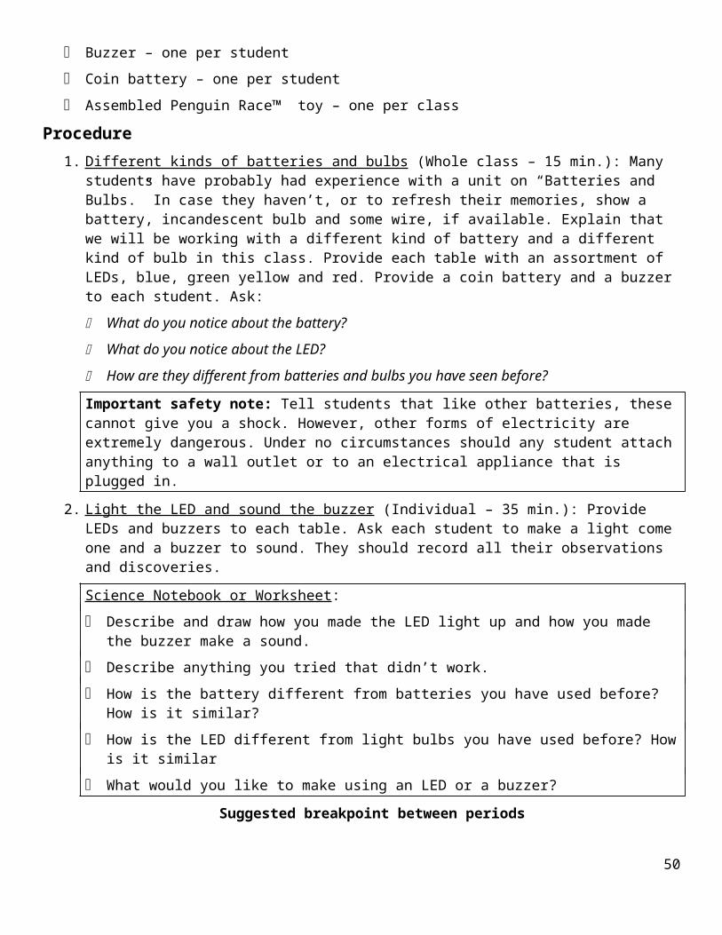
Lesson 5: Make a Simple ElectroCity!Essential QuestionWhat can you create using batteries, LEDs, buzzers, motors and switches?Task Make a scene, story or idea come alive with light, sound & motion effects.
Standards CCLS -- ELA
Speaking & Listening: Presentation of knowledge and ideasLanguage: Vocabulary acquisition and use
NGSS
Cross-cutting Concepts: 4. Systems and system models; 6. Structure and functionDisciplinary Core Ideas: ETS1. Engineering Design
Outcomes Students use sketches and schematic diagrams to plan, build and troubleshoot their own circuits.
Students apply the knowledge they have gained about electricity to create their own displays
Students develop troubleshooting strategies and techniques to address issues as they arise.
AssessmentObjective: Below (1) Approaching (2) Proficient (3) Advanced (4)
A. Draw and describe the story, scene or idea
No drawing or description
Some drawing or writing; details missing, such as locations of devices or idea is too simple
Well-thought-out concept involving multiple circuits, clearly described via writing and drawing
Complex, innovative design
B. Create a diagram for each circuit
No diagram Diagrams are unclear, incomplete and/or lacking switches
Clear diagrams of basic circuits
Accurate diagrams of complex circuits, e.g., including multiple switches
C. Build, test and troubleshoot an ElectroCity
Nothing built Parts are not working; difficulty in troubleshooting
ElectroCity works as planned; evidence of troubleshooting to make it work
Elaborate and/or multiple ElectroCities and/or assistance to other students in troubleshooting
Advance Preparation Photocopy worksheets and rubrics
Bring in a sample ElectroCity that you or a student has made
Materials Motors, AA batteries, wheels, LEDs, coin batteries, buzzers, hook-up wire, wire strippers
Paper fasteners, cardstock, craft supplies rubber bands, tape
Procedure50

1. Planning an ElectroCity : (Small groups -- 15 min.) Explain to students that they will next have an opportunity to design an ElectroCity, using any of the materials they have learned about. An ElectroCity is a display that includes a circuit to make an idea, scene or story come alive with light, sound and/or motion effects. The ideas for these could be linked to an existing classd theme, such as a neighborhood walk, a story, period of history, or science topic. The first step is to write a description of the scene each group would like to create, and draw a picture of what it will look like. Next they should explain how they will use a circuit to make their scene come alive.
Science Notebook:
Describe and draw the scene you would like to create.
Make a drawing showing what the scene will look like.
How will you use an electric circuit to make your scene come alive?
2. The electrical design : (Small groups – 30 min.) Review the use of schematic symbols, conventions and diagrams. The next step is to make a design of the circuit(s) that will be at the heart of the ElectroCity. The one rule is that every circuit should be controlled by a switch. Encourage students to use the circuit symbols they have learned, and the conventions for connecting parts.
Suggested breakpoint between periods
3. Making and troubleshooting the ElectroCity : (Small groups – 50 min.): Provide time for students to create their ElectroCities, based on the designs they have already completed. As they are working, ask students to keep lists of issues – things that don’t work. It is likely that some aspects of some of the electrical circuits will not work. Ask students:
If something doesn’t work the way you want it to, what should you do?
Develop the idea that it doesn’t make sense to start over, because most of what you made is probably OK. Also, if you start over, you might just run into the same issue again! It makes much more sense to:
Find out exactly what is preventing it from working, and
Then solve only that problem.
In engineering, this way of addressing issues is called troubleshooting.
Most of the problems will probably be due to bad connections, although there may also be failures due to bad components. For suggestions, see Teacher Notes for Lesson 5.
Word bank Design, plan, troubleshooting
HomeworkHidden Switch Hunt: Using the worksheet, list examples of hidden switches that you find at home. A hidden switch is one that you don’t usually see. You turn it ON or OFF by doing something else, which causes the switch to open or close. For example, a refrigerator contains a hidden switch. When you open the door, a light comes on, but you didn’t turn the light on deliberately. Its switch is hidden, and operated by the opening and closing of the door. The first row of the Worksheet, Part 2, is already filled in with the refrigerator example. Ask students to list their examples on the Worksheet. For each one, they should identify the device that contains the switch, what the switch controls and what has to happen to activate the switch.
Name: _____________________ Date:_______________51

Lesson 5, Part 1: Making an ElectroCityMake a schematic diagram of the circuits you will use:
Make a list of the issues that arose, and what you did to fix each one:
Issue Fix
___________________________________
___________________________________
___________________________________
___________________________________
___________________________________
___________________________________
___________________________________
___________________________________
___________________________________
___________________________________
___________________________________
___________________________________
___________________________________
___________________________________
___________________________________
___________________________________
___________________________________
___________________________________
52

Name: _____________________ Date:_______________Lesson 5, Homework: Hidden Switch Hunt
List the hidden switches you found at home or in the classroom, or that you thought of afterwards. The first row is completed as an example.
Where I found it What it controls What do you do to operate the switch ?
Refrigerator The light inside Open or close the door
Lesson 6: Hidden SwitchesEssential QuestionWhat is a hidden switch and how does one work?
Task
53

Create a hidden switch and use it to control light, sound or motion.
Standards CCLS -- ELA
Writing: Text types and purposes; Research to build and present knowledgeSpeaking & Listening: Comprehension and collaborationLanguage: Vocabulary acquisition and use
NGSS
Scientific & Engineering Practices: 1. Asking questions and defining problems; 3. Planning and carrying out investigations; 4. Systems and system models; 6. Structure and functionDisciplinary Core Ideas: PS2: Motion and Stability; ETS1. Engineering Design
Outcomes Students recognize that some switches are hidden, and come up with examples of these;
Students make their own hidden switches;
Students design, build, test and troubleshoot a device controlled by a hidden switch.
Assessment
Objective: Below (1) Approaching (2) Proficient (3) Advanced (4)
A. Identify and record examples of hidden switches
No examples found
One or two examples found, but no explanation of how it operates and/or what it controls
Multiple examples, with explanations of how each one operates and what it controls
Multiple examples, plus conjectures about how some hidden switches work
B. Design and make the hidden switch
No hidden switch
Switch is not constructed well and would not be reliable
Demonstrates a reliable switch
Reliable switch, plus ideas about how switch can be adjusted to modify its operation
C. Build, test and troubleshoot a gadget that is controlled by a hidden switch
Nothing built Parts are not working; difficulty in troubleshooting
Gadget works as planned; evidence of troubleshooting to make it work
Working gadget, plus suggestions about how it could be redesigned to work differently
Advance Preparation Make several of the sample hidden switches: a) Switch activated when card closes; b) Switch activated
when card opens; c) Switch activated when box closes d) Switch activated when box opens. For directions, see Teacher Notes for Lesson 6 or www.citytechnology.org/node/1930/tdesign#
Photocopy worksheets and rubrics
Post a sheet of chart paper to debrief the Hidden Switch Hunt, with columns labeled “Found where?” “Controls what?” & “Operates how?”
Materials Same materials as for Lesson 5 : Motors, AA batteries, wheels, LEDs, coin batteries, buzzers, paper
fasteners, paper clips, hook-up wire, wire strippers, rubber bands, cardstock, scissors, tape, craft supplies.
54

Additional materials : Cardboard boxes, clothespins
Sample gadget controlled by a hidden switch
Procedure1. The Hidden Switch Hunt : (Whole class – 10 min.) Use the chart paper to debrief examples of hidden
switches that students have found for Homework. Alternatively, students could list their examples themselves, at the beginning of class. Discuss each example briefly:
When they designed this device, why do you think they decided to hide the switch?
What action do you have to take to operate the switch?
How do you think the hidden switch works?
Introduce the terms manual and automatic. Ask:
What makes an action automatic?
How can a hidden switch be used to make something happen automatically?
2. How to make a hidden switch : (Whole class – 10 min.) Ask students for ideas about how to make the hidden switches they will need to control their gadgets. If necessary demonstrate some of the sample hidden switches you have made.
3. What can you make that’s controlled by a hidden switch ? (Whole class – 10 min.; small groups ) Show the students the small boxes and the clothespins (they have already seen the other materials). Conduct a brainstorming session, for students to come up with ideas of hidden-switch-controlled gadgets they could make. It is likely that they will come up with ideas on their own, but if necessary, you can share a sample device or some ideas for gadgets.
4. Design a gadget controlled by a hidden switch (Small groups – 20 min.) Encourage each student to plan and design a gadget. They should use the Worksheet to record their ideas and plan what they will make.
Suggested breakpoint between periods
5. Make your gadget (Individual – 50 min.): Provide students with materials and time to work on their gadgets. Much of their work is likely to be self-directed, and some students will probably be able to help others. Assist them only enough so that they don’t become frustrated.
Science Notebook: Keep a record of what you did, things that didn’t work, troubleshooting strategies you used, and how you fixed anything that didn’t work. What did you learn?
Word bank Design, plan, troubleshooting
ExtensionClothespin switch: Design and make an alarm system controlled by a clothespin switch.
55

Name: _____________________ Date:_______________Lesson 6: Make a Gadget Controlled by a Hidden Switch
What would you like to control with a hidden switch?________________________________________________________________________________________________________________________________________________________What will you have to do to make the switch turn ON and OFF?________________________________________________________________________________________________________________________________________________________Where will you hide the switch?________________________________________________________________________________________________________________________________________________________
Make a drawing of what your gadget will look like:
Make a Schematic diagram of the circuit you will use:
56

Lesson 7: Shakers and NoisemakersEssential QuestionWhat causes vibrations and noise?
Task Create a motorized device that shakes when you turn it on, and another that makes noise.
Standards CCLS -- ELA
Writing: Text types and purposes; Research to build and present knowledgeSpeaking & Listening: Comprehension and collaborationLanguage: Vocabulary acquisition and use
NGSS
Scientific & Engineering Practices: 1. Asking questions and defining problems; 3. Planning and carrying out investigations; 7. Engaging in argument from evidence; 8. Obtaining and evaluating information
Crosscutting Concepts: 1. Patterns; 2. Cause and effect: mechanism and prediction; 5. Energy and matter: flows, cycles and conservation
Disciplinary Core Ideas: PS2: Motion and Stability; PS3: Energy
Outcomes An off-center weight on a rotating wheel will make the wheel vibrate.
When one thing hits another repeatedly, it will keep making noise.
Assessment
Objective: Below (1) Approaching (2) Proficient (3) Advanced (4)
A. Create a device that vibrates
No device Device does not vibrate
Device vibrates, and student can explain what makes it vibrate
Modifies device to make it vibrate more or less
B. Create a device that makes noise
No device Device does not make noise automatically
Device makes noise automatically, and student can explain why
Device makes noise, and student can show how to change volume or pitch
Advance Preparation Make a few motor circuits, as in Lesson 4. Attach a wheel to each motor. Set aside some weights, such
as paper clips, paper fasteners and coins, and tape them in various places on the wheel, until you get the wheel to vibrate. Then remove the weights and save them. Also set aside a few pieces of cardstock and rubber band for attaching to the wheels to create noise.
Photocopy worksheets and Assessment
Post a sheet of chart paper to list examples of things that vibrate (see Procedure, Step 1), and another for showing things that make noise (see Procedure, Step 2)
57

Materials Per pair of students:
AA battery, motor and wheel
General supplies
Materials for making circuits: rubber bands, paper fasteners, wire, wire strippers
Small weights, such as coins, paper fasteners or metal washers
Craft materials
Procedure1. What makes something vibrate? (Whole class – 20 min.) Lead a brief class brainstorming session to
collect examples of things that vibrate. List them on chart paper. Ask:
What can you think of that vibrates?
Which of these things has a motor? What causes the vibrations?
What do you think makes a washing machine vibrate?
When does a dryer vibrate?
Develop the idea that when something is turning rapidly, it will vibrate if more of the weight is on one side than on the other. For example, a washing machine or dryer vibrates when the wash gets bunched up on one side of the rotating bucket.
To demonstrate this effect, turn on a motor with a wheel attached. Hold the motor while it is turning -- it should run fairly smoothly. Then disconnect the motor from the battery, and tape a weight near the edge of the wheel, as far out as it can go (see Advance Preparation). Turn the motor on again, and let students hold the motor this time. They should feel it vibrating. Ask:
What does it feel like now?
What is making it shake?
How do you think this shaker is similar to a vibrating washing machine?
How do you think you could you make it vibrate more or less?
What do you think is inside a cell phone that makes it vibrate?
A cell phone vibrator works the same way as the vibrator you have just demonstrated – a little motor turns really fast with an off-center weight that makes it vibrate.
2. Make a shaker (Individual – 30 min.) Provide materials for students to make and explore their own shakers. Suggest adding beads or another small objects inside a vibrating box. They can use their Science Notebooks to record their ideas and findings.
Suggested breakpoint between periods
58

3. Noisemakers (Whole class – 15 min.) Remind students about how they used a motor to make a shaker. Ask:
How do you think I could use the same motor to make a noise?
Make a list of students’ ideas on chart paper. Use the same motor and wheel as before, but remove the weight. Make a flap by taping a rubber band or piece of paper so it extends beyond the edge of the wheel. Hold it so the flap just scrapes against the surface of a desk or table each time it comes around. Turn the motor on and ask students to listen. Can they hear it?
What is making that noise?
How would you make your own noisemaker?
How do you think you could change it to make the noise louder or softer?
Review the concept of pitch, by singing or talking first in one pitch (high or low), followed by another (the opposite). If a musical instrument is available, you can also use it demonstrate a change of pitch.
How do you think you could change its pitch?
Ask students for other ideas for making noise:
a flap could hit a suspended string or rubber band instead of the side of the box,
there could be a bead at the end of the flap,
the motor could rotate a tube with beads inside, etc. 4. Make a noisemaker (Individual – 25 min.) Provide materials and time for students to make their own
noisemakers.
Science Notebook
How can you make a shaker? Make a diagram. Label all parts.
What experiments did you try with shakers? What did you learn?
How can you make a noisemaker? Make a diagram. Label all parts.
Word BankVibrate, shake, balanced, unbalanced, noise, sound, volume, softer ,louder, pitch, higher pitch, lower pitch
Extension: Control a noisemaker or a shaker with a hidden switch
59

Name: _____________________ Date:_______________Lesson 7: Noisemakers and Shakers
How I made a shaker (draw and write)________________________________
________________________________
________________________________
________________________________
________________________________
________________________________
________________________________
What makes it vibrate? ______________________________________________________What could you do to make it vibrate more? ________________________________________________________________________________________________________________How I made a Noisemaker (draw and write):
________________________________
________________________________
________________________________
________________________________
________________________________
________________________________
________________________________
Why is it making noise? ______________________________________________________How could you make it louder? ________________________________________________
60

How could you make the pitch lower? __________________________________________How could you make the pitch higher? _________________________________________
Lesson 8: Things that Glow in the Dark Essential QuestionWhat can make writing glow in the dark?
Task Create a secret message and use ultraviolet light to make it glow in the dark
Standards CCLS -- ELA
Writing: Text types and purposes; Research to build and present knowledgeSpeaking & Listening: Comprehension and collaborationLanguage: Vocabulary acquisition and use
NGSS
Scientific & Engineering Practices: 1. Asking questions and defining problems; 3. Planning and carrying out investigations; 7. Engaging in argument from evidence; 8. Obtaining and evaluating information
Crosscutting Concepts: 1. Patterns; 2. Cause and effect: mechanism and prediction; 5. Energy and matter: flows, cycles and conservation
Disciplinary Core Ideas: PS3: Energy; PS4: Waves and their Applications in Technologies for Information Transfer
Outcomes All the colors we see are forms of visible light. Ultraviolet light is a form of light that is not visible.
Ultraviolet light can make a fluorescent dye glow in the dark.
Assessment
Objective: Below (1)
Approaching (2) Proficient (3) Advanced (4)
A. Identify and describe properties of different forms of light
None identified
Aware that some forms of light are not visible, and that visible light exists in a variety of colors
Aware of ultraviolet as a form of light that is not visible
Able to describe some properties of ultraviolet light
B. Design and construct a device that uses ulatraviolet light to make writing glow in the dark
No device Device does not make fluorescent writing glow in the dark
Device does make fluorescent writing glow in the dark and is controlled by a switch
Experiments with a variety of colors of paper to find the effect of UV light on each one
61

Advance Preparation Make a simple circuit with an ultraviolet (UV) LED and two coin batteries, as shown in the Teacher
Notes for Lesson 8, as well as at http://citytechnology.org/node/1932 . Use a fluorescent highlighter to draw on yellow cardstock. In ordinary light, the mark should be barely visible. Use the UV LED to make the mark glow. Enhance the effect by looking at the mark in a dark place, such as under a desk or table.
Photocopy Worksheet and Assessment
Materials
Per pair of students:
Two coin batteries and one UV LED (clear bulb with round top)
General supplies:
Scissors, tape, rubber bands, paper fasteners, hook-up wire, wire strippers
Fluorescent highlighters, cardstock in assorted colors
Boxes and craft materials
Procedure1. Things that glow in the dark : (Whole class – 10 min.): Use a fluorescent highlighter to make a mark on a
yellow piece of cardstock. Ask students:
Can you see the mark I just made?
What could I do to make it glow brighter?
Shine the UV LED on the yellow mark. Then ask someone to turn off the lights. The mark should glow an eerie yellow-green color.
What do you think is making this glow?
What could you use this for?
Explain that the LED you used is producing ultraviolet light, UV for short. Light comes in many different forms. We can see colors ranging from red, orange, yellow, green, blue and violet (purple), but other forms of light are not visible to us. The range of light is called the spectrum, and the light just beyond violet is called Ultraviolet. It is a form of light that is not visible, but it can have effects that are visible. One effect is that ultraviolet light can make a fluorescent material glow – such as the dye in the highlighter.
2. Make something that glows in the dark (Individual – 25 min.) Distribute coin batteries, UV LEDs and yellow cardstock. Provide time for students to make their own images or messages that glow in the dark.
3. Experiment with different colors of paper (Individual – 15 min.) Distribute other colors of cardstock: green, blue, brown, red and purple. Suggest that students use their markers to write on each one, and compare the results..
Science Notebook
What can you do with a UV LED?
What happens when you try using different paper colors?
What did you learn from this lesson?
62

Word BankLight, color, spectrum, visible, ultraviolet, fluorescent,
Extension: Make a light box with a secret message inside. When you close the box, the light comes on, controlled by a hidden switch, and you can see the secret message through a peephole.
Name: _____________________ Date:_______________Lesson 8: Things that Glow in the Dark
How I made a message or picture that glows in the dark:________________________________
________________________________
________________________________
________________________________
________________________________
________________________________
________________________________
________________________________
________________________________
What makes it glow? ____________________________________________-_______________________________________________________________________________________What could you do to make it glow brighter? ______________________________________________________________________________________________________________How is Ultraviolet light different from ordinary light?________________________________________________________________________________________________________________________________________________________How are Ultraviolet and ordinary light similar?________________________________________________________________________________________________________________________________________________________
63

What would you like to make using an Ultraviolet LED and fluorescent marker? ____________________________________________________________________________________________________________________________________________________________________________________________________________________________________
Lesson 9: Infrared Remotes
Essential QuestionHow is it possible to turn something on from a distance?
Task Create a remote control device that uses infrared light to trigger a hidden switch
Standards CCLS -- ELA
Writing: Text types and purposes; Research to build and present knowledgeSpeaking & Listening: Comprehension and collaborationLanguage: Vocabulary acquisition and use
NGSS
Scientific & Engineering Practices: 1. Asking questions and defining problems; 3. Planning and carrying out investigations; 7. Engaging in argument from evidence; 8. Obtaining and evaluating information
Crosscutting Concepts: 1. Patterns; 2. Cause and effect: mechanism and prediction; 5. Energy and matter: flows, cycles and conservation
Disciplinary Core Ideas: PS3: Energy; PS4: Waves and their Applications in Technologies for Information Transfer; ETS2: Links among engineering, technology and society
Outcomes A communication system includes a transmitter, a receiver and a signal
Infrared light is not visible, but it can operate a hidden switch.
Infrared light has some of the characteristics of visible light, but not others
AssessmentObjective: Below (1) Approaching (2) Proficient (3) Advanced (4)
A. Describe the functions of the transmitter, receiver and signal in a communication system
No description Awareness of need for transmitter and receiver, but unclear about the function of each one
Describe how the transmitter sends out a signal, which the receiver is able to detect
Provides examples of communication systems that use different kinds of signals
B. Create and test an infrared (IR) communication system
No transmitter nor receiver
Transmitter or receiver circuit, but not both
Transmitter and receiver both work reliably
Assists other students in troubleshooting transmitter and/or
64

receiver
C. Explore the properties of infrared light
No exploration Recognizes that transmitter and receiver must be aligned
Explores how distance and angle affect the system
Looks for other sources of infrared light, and other methods of detecting infrared
Advance Preparation Create chart labeled Communication Systems Examples, with headings: “System,” “Transmitter,”
“Receiver,” and “Signal.”
Create a chart showing diagrams of infrared transmitter & receiver; see below:
Make a sample infrared transmitter and receiver; see Advance Preparation videos in www.citytechnology.org/energy-system/9-infrared-remotes
Bring in a TV, DVD or stereo remote; a cell phone and an ordinary flashlight (not one with an LED or fluorescent bulb)
Photocopy worksheets and Assessment
Materials One per class:
TV, DVD or stereo remote
Cell phone
Flashlight with incandescent bulb
Per student:
Two coin batteries, one IR transmitter and one IR receiver and one LED
General supplies
Materials for making circuits: rubber bands, paper fasteners, wire, wire strippers, tape
65

Straws, pieces of plastic, cardboard, tennis ball
66

Procedure1. Communication systems (whole class – 15 min.) Lead a discussion about different kinds of
communication systems. Ask:
What do you think we mean when we say “communication system”?
What communication systems can you think of? What do they do?
List the examples in the leftmost column of the chart, under “Systems.” For each system, guide the student to identify the transmitter, which sends a signal of some kind, the receiver, which accepts the signal, and puts it in a form we can use, and the type of signal. Here are some examples to start with:
System Transmitter Receiver Signal
U.S. Mail Letter writer Addressee Written pages
Radio Radio station Radio Radio waves
Conversation Vocal cords & mouth Ears Sound waves
Sign language Hands Eyes Sign language symbols
After collecting examples, ask students:
How do you think a remote controller communicate with a TV set or DVD player?
Students may be surprised to learn that a remote controller uses infrared light to send signals to the TV or DVD player. Help them recall that infrared light is a form of light that is not visible, like the ultraviolet light they used in Lesson 8. In this lesson, they will be making their own infrared remotes.
2. Circuit drawing and diagram for an IR remote (Whole class – 15 min.): Demonstrate the sample IR receiver/transmitter pair you have made, and explain. An IR transmitter is an LED that produces IR instead of visible or UV light. An IR receiver is a type of switch called a phototransistor that turns on when exposed to IR light. Both the IR receiver and transmitter look like LEDs, but in different colors. The receiver is black and the transmitter is purple. Each of them has a short and a long wire, one (+) and one (—), but they are opposite from all the other LEDs. Emphasize this point:
On the IR transmitter and receiver, the short wire is (+) and the long wire is (—)
Show students the chart you have made of the circuit drawing and diagram for the IR transmitter and receiver, and review each circuit:
A transmitter circuit (right) that consists of a coin battery and an IR transmitter, or LED.
A receiver circuit (left) that consists of two coin batteries, a red, LED and a receiver, or switch, that closes when the IR light is detected.
The LED comes on when the receiver has been activated by the infrared signal. The only connection between these two circuits is the IR light that passes from the transmitter to the receiver, closing the switch. Notice that the circuit symbol for the receiver has the arrows pointing inwards, to indicate that it receives light, the opposite of an LED.
3. Make your own IR remote (Pairs – 20 min.)
Distribute materials for making IR receivers and transmitters. Suggest that one student in each pair makes the transmitter, and the other makes the receiver, and that they try to get them to work together. If the transmitter and receiver are both working properly, the red LED will come one when the transmitter
67
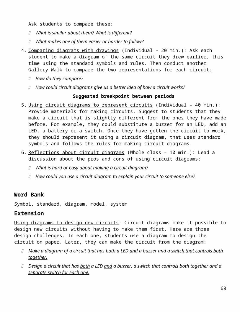
is aimed directly at the receiver. There will be more time later in the lesson to mount these circuits and add switches.
Suggested breakpoint between periods
4. Create a communication system that uses an IR remote (Individual – 50 min.) Based on what they have done so far, suggest that each student create his or her own system. Remind them that the transmitter circuit should have a switch, so that it is not ON all the time. If students ask about putting a switch in the receiver circuit, point out that the receiver circuit already includes a hidden switch, the phototransistor, which is triggered by infrared light. Encourage students to be creative: they could use another color LED, a buzzer instead of a light, create a mystery box controlled by a remote, etc. For further ideas, see Extensions, below.
Science Notebook
How does an IR transmitter/ receiver pair work? What can you use it to do?
What did you learn about infrared light using the transmitter/receiver pair?
Word BankCommunication, transmitter, receiver, phototransistor, signal, remote, infrared, incandescent, fluorescent
ExtensionExperiments with Infrared Remotes
1. Seeing the IR transmitter
Turn on the transmitter, and look at it in a dark area, such as under a table or desk or inside a closet. What can you see? Is any of its output visible, and if so, what color?
Another way to see the IR LED is to turn it ON in front of a cheap camera, such as a cell phone camera. You should see a bright white glow! Why can the camera see it so well?
2. Other sources of IR light
Because IR light is invisible, we are not aware of the many other sources of IR in our environment. Ask students to investigate other possible sources of IR light:
Which of these light sources will turn on the IR receiver:
a) sunlight, b) light from an incandescent bulb, c) light from a fluorescent bulb, d) light from an LED, e) the signal from A TV or DVD remote controller?
3. Turning on a buzzer
Replace the LED with a buzzer. Turn the buzzer on from a distance.
68

4. Obstacles
What happens if things get in the way between the transmitter and receiver? What kinds of things will let the IR light through and what materials will block the light? Try cellophane, transparency film, piece of paper, your hand, etc.
receivertransmitter
?
What kinds of obstacles block visible light?
How are they similar to or different from the obstacles that block IR light?
5. Mirrors
Set up a receiver and transmitter so the light from the transmitter has to bounce off a surface to get to the transmitter. What kinds of surface will reflect IR light? Try a piece of aluminum foil (both sides), a piece of shiny plastic of any color, dull plastic, paper, transparency film, etc.
receivertransmitter
mirror
What kinds of surfaces reflect visible light?
How are they similar to or different from the surfaces that reflect IR light?
6. The range of the transmitter
Move the transmitter gradually further and further from the receiver, as shown below. How close does the transmitter need to be to the receiver to turn it on?
receivertransmitter
69

To test the sensitivity of the receiver, it is important to align the transmitter so it is in a straight line with the receiver. An easy way to do this is to put them at either ends of an ordinary drinking straw.
receivertransmitter
drinking straw
If you would like to place them further apart than one straw-length, you make a chain of straws, but cutting slits at the end of every other straw, and slipping the slit straws over the other straws. The diagram below shows how to connect two straws:
c) push the slit end over the end of the other
b) cut a short slit lengthwise in one
a) showing the ends of two straws
d) use tape to secure both straws
7. Using a spherical mirror:
Another way to overcome the alignment problem is to use a spherical mirror. You can make a spherical mirror by cutting a tennis ball in half and coating the inside surface with aluminum foil. The light can come from along any of the dotted lines, and the mirror will reflect it to the receiver.
70

Name: _____________________ Date:_______________Lesson 9: Infrared Remotes
How I made an Infrared remote controller (draw & write):_______________________________
_______________________________
_______________________________
_______________________________
_______________________________
_______________________________
_______________________________
_______________________________
_______________________________
_______________________________
What makes the red LED come on? _______________________________________________________________________________________________________________________Where is the hidden switch? _____________________________________________________________________________________________________________________________What activates the hidden switch? _______________________________________________________________________________________________________________________How does a TV remote work? ____________________________________________________________________________________________________________________________How is infrared light similar to visible light? ______________________________________________________________________________________________________________How is infrared light different from visible light? _____________________________
71

____________________________________________________________________________
72

Lesson 10: Design an ElectroFying ElectroCityEssential QuestionWhat can you create using batteries, LEDs, buzzers, motors, hidden switches and IR remotes?
Task Design a mystery box, construction or card that surprises you with sound, light and/or motion when you trip a hidden switch.
Standards CCLS -- ELA
Speaking & Listening: Presentation of knowledge and ideasLanguage: Vocabulary acquisition and use
NGSS
Scientific & Engineering Practices: 1. Asking questions and defining problems; 3. Planning and carrying out investigations
Crosscutting Concepts: 2. Cause and effect: mechanism and prediction 6. Structure and function
Disciplinary Core Ideas: ETS1: Engineering Design
OutcomeA complex design needs to be planned from beginning to end. For an electrical device with a hidden switch, the plan should include a description of the project, a drawing of the hidden switch and discussion of how it will be activated, an overall drawing showing all the components, and an electrical diagram using standard symbols.
Assessment
Objective: Below (1) Approaching (2) Proficient (3) Advanced (4)
Draw and describe the ElectroFying ElectroCity
No drawing or description
Some drawing or writing; but idea is vague or too simple and/or does not use hidden switches
Well-thought-out concept involving a variety of circuits, at least some controlled by hidden switches
Complex, innovative design, presented clearly
Advance Preparation Label a sheet of chart paper Ideas for ElectroFying ElectroCities
Photocopy worksheet and Assessment
Materials Same materials as for Lessons 6-9 : Motors, AA batteries, bushings and wheels, LEDs, coin batteries,
buzzers, paper fasteners, paper clips, aluminum foil, wire, rubber bands, cardstock, scissors, tape, small cardboard boxes, clothespins, IR and UV devices.
Craft materials
Storage bags to hold work-in-progress.
73

Procedure1. Brainstorming ideas for ElectroFying ElectroCities (Whole class – 20 min.) Review all the devices
available for making ElectroCities: batteries, LEDs, buzzers, motors, wheels, switches, hidden switches, magnets, magnetic switches, vibrators, noisemakers, infrared remotes, things that glow in the dark. Students may have already come up with ideas for their own ElectroCities. If not, conduct a brainstorming session in which students present their initial ideas for things they would like to make.
2. Planning an ElectroFying ElectroCity (Small groups – 30 min.) Students should work on their projects in small groups or pairs. Ask students to draw and describe their ideas.
Science Notebook
Describe what you plan to make.
Make a drawing showing how the hidden switch will work. Explain what action will be needed to make the switch open and close.
Make a drawing showing where all the parts will be.
Use standard circuit symbols to make a diagram of the circuit you will use.
ExtensionSeries and Parallel Circuits: Here are two circuits. Each one includes Ask students to predict what each one will do, then build each one and try them to find out:
The next pair of experiments requires two coin batteries per circuit, and two LEDs: one green or blue, and the other red or yellow. These are most easily arranged in a stack, so the (+) side of the top battery is pressing against the (—) side of the bottom one, as in the UV LED circuit in Lesson 8, and the IR Receiver circuit in Lesson 9. The parallel connection in c) is easy to make by pressing the wires from the two LEDs against the battery stack. The series connection in d) can be made by taping the long wire from the blue LED to the (+) side of the battery stack, and the short wire from the red LED to the (—) side of the battery stack, and then completing the circuit by touching the two loose wires together.
74

Name: _____________________ Date:_______________Lesson 10: Design an ElectroFying ElectroCity
What would you like to make?____________________________________________________________________________________________________________________________________What parts will you need?____________________________________________________________________________________________________________________________________Where will the hidden switch be? ___________________________________What will someone have to do to operate it?___________________________________________________________________________________________
Make a drawing of your ElectroFying ElectroCity:
Use standard symbols to make a diagram of the circuit:
75

Lesson 11: Make an ElectroFying ElectroCity Essential QuestionWhat issues arise as you create you ElectroCity and how can you address them?
Task Complete the mystery box, construction or card that you designed in Lesson 10.
Standards CCLS -- ELA
Speaking & Listening: Presentation of knowledge and ideasLanguage: Vocabulary acquisition and use
NGSS
Scientific & Engineering Practices: 3. Planning and carrying out investigations
Crosscutting Concepts: 2. Cause and effect: mechanism and prediction; 4. Systems and system models; 6. Structure and function
Disciplinary Core Ideas: ETS1: Engineering Design
OutcomesStudents develop troubleshooting techniques to address the challenges in creating a complex system, including esthetics structures, mechanisms and circuits as subsystems.
AssessmentObjective: Below (1) Approaching (2) Proficient (3) Advanced (4)
A. Build, test and troubleshoot an ElectroFying ElectroCity
Nothing built
Parts are not working; difficulty in troubleshooting
ElectroCity works as planned; evidence of troubleshooting to make it work
Elaborate and/or multiple ElectroCities and/or assistance to other students in troubleshooting
Advance Preparation Photocopy Assessment
Materials Partially completed ElectroCities from Lesson 10
Same materials as for Lesson 10
Procedure1. Review of troubleshooting and systems (Whole class – 20 min.) Students should have begun working on
their ElectroCity projects, before you conduct this discussion. Ask:
What are some things that didn’t work the way you wanted them to?
Who had a similar problem? What did you do about it?
76
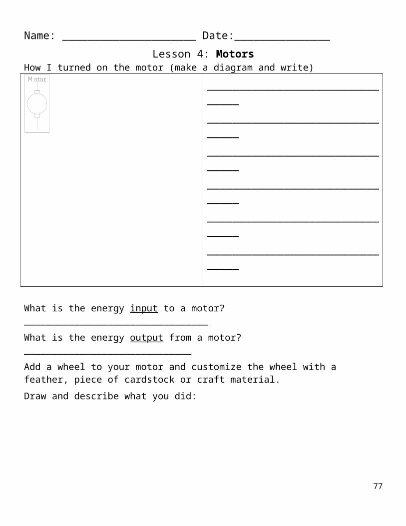
Review basic troubleshooting strategies from Lesson 2. Also, develop the idea that the projects they are making are complex systems. They are composed of subsystems include the esthetic design, structures, circuits and probably mechanisms. These all have to work together. Ask:
In your design, what’s an example of a structures problem? An esthetic design problem? A mechanism problem? A circuit problem?
What issues came up in getting all the subsystems to work together?
2. Ongoing work on the ElectroCities (Small groups – 130 min.) Students continue working on their group projects. Convene the whole class when appropriate for discussion like the one above.
Science Notebook
Write and draw what you made.
List the problems that came up, and what you did to troubleshoot each one.
What did you learn from doing this project?
3. Instructions for using your ElectroCity : Someone might not know what they would have to do to activate the device. Ask each student to attach a short instruction guide, such as “Close the Box and look through the hole,” which will tell the user what to do.
Word Bank Esthetic design, complex system, subsystem, structure
ExtensionThe Digital Multimeter is a very useful tool for troubleshooting circuits. Learn the functions of the digital multimeter, and use it answer questions like:
How are different kinds of batteries different?
How can you tell if wires or connectors are making contact?
Why does the red or yellow LED turn the blue or green one off?
What happens to the battery as you add more weight to a motor shaft?
77

Lesson 12: Present your ElectroCityEssential QuestionHow can others find out about what you did and what you learned from making an ElectroCity
Task Present your group’s ElectroCity to an audience
Standards CCLS -- ELA
Speaking & Listening: Presentation of knowledge and ideasLanguage: Vocabulary acquisition and use
NGSS
Scientific & Engineering Practices: 3. Planning and carrying out investigations
Crosscutting Concepts: 2. Cause and effect: mechanism and prediction; 4. Systems and system models; 6. Structure and function
Disciplinary Core Ideas: ETS1: Engineering Design
Advance Preparation Prepare space and invite audience for presentations
Materials ElectroCities completed in Lesson 11
OutcomeCommunicating information and ideas is a major part of developing new knowledge
AssessmentObjective: Below (1) Approaching (2) Proficient (3) Advanced (4)
A. Present an ElectroCity to an audience
No presentation Presentation is unclear or incomplete; can’t articulating how it works or what troubleshooting was done
Demonstration of ElectroCity including description of how it works and/or troubleshooting that was done
Presentation of all aspects of design, including why it was selected, how it works, troubleshooting and how it could be improved
Procedure1. Presenting ElectroCities (Whole class – 50 min.) This is the culminating lesson, where students will
present their final products to an audience. The display could take one or more of several forms:
Formal presentation: Each group shows their ElectroCity to an audience and explains what he or she did to make it.
Museum: Students create a display on tables, where visitors can view the ElectroCities and try them out for themselves
78

Invention Convention: Like a Science Fair, visitors come to view the ElectroCities, test them out and talk with the students who made them.
79

GlossaryAutomatic: describes something that happens without deliberate action by the user
Balanced: describes weights that offset one another, so that no one side is heavier than any other
Battery: a source of electricity, which operates by converting chemical to electrical energy
Battery holder: a fixture that holds a battery in place and provides connectors for attaching wires conveniently
Buzzer: a device that converts electrical energy to sound energy
Charge: a basic unit of electricity, provided by a battery or another source
Circuit: a system that guides the flow of electricity, and converts electrical energy into some other form
Clockwise: the direction of motion of a standard clock: left to right on top; right to left on the bottom
Communication: the process fof moving information from one place to another
Complex system: a system that has at least two subsystems, each of which could be a system in itself
Conductor: a material that supports the flow of electricity; nearly all common conductors are metals
Connector: a part that provides an electrical connection from a component such as a battery to wires leading to other parts of a circuit
Contact: one of the connectors of a switch
Control: a device that regulates the flow of energy; examples are faucets, valves, circuit breakers and switches
Counterclockwise: the opposite direction from clockwise
Current: the flow of electrical charges, which carry electrical energy
Design: the process or activity of planning something new
Diagram: a 2D graphic model showing the essential components and structure of a system
Direction: the path of motion of a moving object
Electricity: a form of energy carried by moving electrical charges
Energy: a quantity that can take many different forms, but that can neither be created nor destroyed
Energy transformation: a change in the form of energy, such as electrical to light, kinetic to heat, etc.
Esthetic design: design elements that are intended to convey an idea, theme, story or mood
Exposed: open to view
Fluorescent light: a device that converts electrical energy almost entirely into white light
Hidden: not open to view
Higher pitch: sound of higher frequency, such as a whistle or a shriek
Incandescent light: a device that converts electrical energy into both light and heat
Infrared: a type of light energy that is below red in the spectrum, and therefore not visible, but that we feel as heat
Input: energy or information that has to be supplied to a system
Insulator: a material that blocks the flow of electricity; the opposite of a conductor; examples are wood, plastic, paper and air
Kinetic energy: the energy carried by a moving object 80

Light: a form of energy that is visible
Light-emitting diode (LED): a device that converts electrical energy into red, yellow, green or blue light load
Louder: describes sound that can be heard more distinctly, or further away from the source
Lower pitch: sound of lower frequency, such as a drum or a rumble
Manual: describes an action that has to be done deliberately by the user; the opposite of automatic
Model: a simplified description of a complex system, showing only the essential elements
Motor: a device that converts electrical energy into kinetic energy of a rotating shaft
Noise: the way sound is experienced by a person
Output: the result of providing an input to a system
Phototransistor: an automatic switch that is turned on by light, allowing electrical energy to pass through
Pitch: the rate at which sound waves vibrate; see also higher pitch and lower pitch
Plan: a method for expressing a future action
Polar: describes an electrical device for which it matters which way the wires are connected
Pull-chain switch: a type of switch that is operated by pulling a chain, for example on a ceiling fan
Push-button switch: a type of switch that is turned on when a button is held down, for example on a keyboard
Receiver: the part of a communication system that converts information from the signal sent by the transmitter into an output the user can understand
Remote control: a switch that can be operated from a distance
Rotary switch: a switch that is operated by turning a component, for example on a table fan or dimmer
Rotation: motion along a circular path
Shaft: the part of a motor that rotates
Shake: move rapidly back and forth
Signal: the aspect of a communication system that carries information from one place to another, such as sound waves in conversation, or radio waves in radio and TV
Slide switch: a switch that is operated by pushing a movable component back and forth
Softer: describes sound that is less distinct or harder to hear
Sound: a form of energy that is carried by rapid vibrations in air or other media
Spectrum: the range of forms of light, including all the colors of visible light, plus other forms, such as ultraviolet and infrared
Standard symbol: a widely accepted means of representing some type of information
Structure: a system whose purpose is support weight or other forces
Subsystem: a part of a system that could itself be a system
Switch: a device that controls the flow of electricity
System: a set of interconnected parts that performs a function, converting inputs into outputs
Toggle switch: a type of switch that can be flipped from one position to another, and locks in either position, such as a standard light switch
81

Transmitter: the part of a communication system that accepts input information from the user and converts it into a signal, to be sent to the receiver
Troubleshooting: a process of addressing a fault or failure in a system by identifying and fixing the cause
Ultraviolet: a type of light that is above violet in the spectrum, and therefore not visible, but has effects we can detect, such as sunburn and fluorescence
Unbalanced: describes weights that are not distributed equally; the opposite of balanced
Vibrate: move rapidly back and forth; another word for shake
Visible: describes anything we can see
Voltage: a measure of electricity that describes the energy carried by moving charges
Volume: the amount of sound energy; see also louder and softer
82