Embed Size (px)
Citation preview

|| Volume 6 || Issue 4 || April 2021 || ISSN (Online) 2456-0774
INTERNATIONAL JOURNAL OF ADVANCE SCIENTIFIC RESEARCH
AND ENGINEERING TRENDS
IMPACT FACTOR 6.228 WWW.IJASRET.COM DOI : 10.51319/2456-0774.2021.4.0004 22
DESIGN AND STATIC DYNAMIC ANALYSIS OF
CENTRIFUGAL IMPELLER WITH CONVENTIONAL AND
COMPOSITE MATERIAL USING VARIOUS MATERIALS
SHAIK BASHA1, Mr. J. NAGARAJU M.Tech.2
M.Tech., Machine Design, Department of Mechanical Engineering Nova College of Engineering &Technology
Jangareddygudem-534447, West Godavari District1
Associate Professor, Department of Mechanical Engineering Nova College of Engineering &Technology Jangareddygudem-
534447, West Godavari District2
--------------------------------------------------------- ***------------------------------------------------------------ Abstract: - Centrifugal pumps are used to transport liquids/fluids by the conversion of the rotational kinetic energy to the
hydro dynamics energy of the liquid flow. The rotational energy typically comes from an engine or electric motor or turbine.
In the typical simple case, the fluid enters the pump impeller along or near to the rotating axis and is accelerated by the
impeller, flowing radially outward into a diffuser or volute chamber (casing), from where it exits. Pumps are widely used for
water supply plants, steam power plants, sewage, oil refineries, chemical plants, hydraulic power service, food processing
factories and mines, because of their suitability in practically any service. Therefore it is necessary to find out the design
parameter, working conditions and maximum efficiency with lowest power consumption, The aim of the project is Design
modification and static dynamic analysis of centrifugal impeller using various materials generally using materials are
conventional material .In this project taken composite materials because of composite materials have high strength and non
corrosion material. non metallic component so, the chattering noise will be low compared to other materials during the
functioning process. Find out the best material on these materials(CFRP ,GFRP, Al 1060,Inconel 625,Inconel 740) to
decrease the weight and increase the efficiency by using the design software is catia and analysis using the Ansys software.
finally find out the stresses, strains, deformations in static analysis and Deformations are find out at different frequencies in
modal analysis .
----------------------------------------------------------------------------***-------------------------------------------------------------------------
I INTRODUCTION
PUMP
A pump is a machine used to move liquid through a piping
system and to raise the pressure of the liquid. A pump can be
further defined as a machine that uses several energy
transformations to increase the pressure of a liquid.
Figure 1 Working principle of Pump
TYPES OF PUMP1.2.1 RECIPROCATING PUMP
In reciprocating pumps the mechanical energy is converted into
hydraulic energy by sucking the liquid into a cylinder in which
a piston is reciprocating(moving backwards and
forwards)which exerts the thrust on the liquid and increases its
hydraulic energy(pressure energy),the pump is known as
reciprocating pump. Reciprocating pumps are used where a
precise amount of liquid is required to be delivered, also where
the delivery pressure required is higher than that can be
achieved with other types. Figure 1.2 shows line diagram of
reciprocating pump.
ROTARY PUMP
Rotary pump is used to move heavy or very viscous fluids.
These employ mechanical means such as gear, cam and screw
to move the liquid.
CENTRIFUGAL PUMPS
It is the rotodynamic machine. By rotating action develop the
pressure able to lifting of liquid lower level to higher level.
Centrifugal pump is explained with the following headings:
W ORKING PRINCIPLE OF CENTRIFUGAL PUMP
Centrifugal pumps works on the basis of second law of
Newton. Due to the rotation of the runner, called impeller the
fluid at the inner radius moves to the outer radius & gain the
Centrifugal head. Suction is created at the inlet to the pump
which is called the eye. Continuous lifting of fluid thus takes
place from sump to the pump while passing through the
impeller the fluid take the energy from vane sin pressure &

|| Volume 6 || Issue 4 || April 2021 || ISSN (Online) 2456-0774
INTERNATIONAL JOURNAL OF ADVANCE SCIENTIFIC RESEARCH
AND ENGINEERING TRENDS
IMPACT FACTOR 6.228 WWW.IJASRET.COM DOI : 10.51319/2456-0774.2021.4.0004 23
kinetic energy. A large amount of impeller outlet therefore
made to convert the kinetic energy of fluid into pressure energy
before the fluid enters the developing pipe.
CENTRIFUGAL PUMP APPLICATIONS
Pumps are used wherever any quantity of liquid must be moved
from one place to another. Pumps are found in such services as
steam power plants; water supply plants; sewage; drainage or
irrigation; oil refineries, chemical plants and steel mills; food
processing factories and mines; dredging or jetting operations;
hydraulic power services and almost every ship whether driven
by diesel or steam engine. While these pumps have much in
common, they are varied to meet special requirements and
particular needs of each service.
¬ Petroleum Industry
¬ Chemical Industry
¬ Textile Industries
¬ Paper Industry
II LITERATURE SURVEY
[1]. A Syam Prasad, BVVV Lakshmipathi Rao, A Babji, Dr P
Kumar Babu , “Static and Dynamic Analysis of a Centrifugal
Pump Impeller” Alloys are playing major role in many
engineering applications. They offer outstanding mechanical
properties, flexibility in design capabilities, and ease of
fabrication. Additional advantages include light weight and
corrosion resistance, impact resistance, and excellent fatigue
strength. In this paper study of static and modal analysis of a
centrifugal pump impeller which is made of three different
alloy materials. (viz., Inconel alloy 740, Incoloy alloy 803,
Warpaloy) The best material for design of impeller is Inconel
740. Specific modulus of Inconel 740 obtained in static analysis
is 10 % higher than other material. The natural frequency in
modal analysis is 6% higher than other material. The
deformation of Inconel 740 in static analysis is reduce by 12%.
[2] Karthik Matta, Kode Srividya, Inturi Prakash , “Static and
Dynamic Response of an Impeller at Varying Effects” An
impeller is a rotating component of a centrifugal pump, usually
made of iron, steel, bronze, brass, aluminum or plastic. The
modeling of the impeller was done by using solid modeling
software, CATIA V5 R18. It is proposed to design a blower
with composite material, analyze its strength and deformation
using FEM software. In order to evaluate the effectiveness of
composites and metal blower and impeller using FEA packaged
(ANSYS). Modal analysis is performed on both Aluminum and
composite centrifugal blower impeller to find out first 5 natural
frequencies. If number of blade and outer diameter increases
stresses and deformation also increases all are allowable limit.
Total analysis result compares and found that composite
materials are having less deformation and stresses.
[3]. G. Kalyan, K.L.N. Murty. “Design and Optimization of
Centrifugal Pump Guide Vanes” In this paper an impeller of a
centrifugal pump is designed and modeled in 3D modeling
software Pro/Engineer.. Materials used are steel and aluminum.
The optimization of the impeller design is done by observing
the results obtained from the analysis performed. The results
considered are stress frequency velocity pressure flow rates.
Analysis is done in ANSYS.
By observing the structural analysis result the stresses by
increasing number of blades andincreasing the angle of blade.
When Aluminum material is used the stresses are less than that
of steel. By observing modal analysis results the frequencies are
reducing by increasing the number of blade .
[4]. Pramod J. Bachche1, R.M.Tayade “Finite Element
Analysis of Shaft of Centrifugal Pump” Centrifugal pump is
world one of the oldest water pumping devises. In this paper
study Shaft of centrifugal pump for static and dynamic analysis.
The shaft is analyzed by using finite element analysis technique
for stresses and deflections. The total work is carried out in two
stages first stage is static analysis. In this stage pump shaft is
analyzed for stresses and deflection and same results are
verified using graphical integration method. And second for
dynamic analysis, in this stage result obtained by static analysis
are used to calculate dynamic forces coming in pump shaft.
Again shaft is analyzed in dynamic input condition and results
are verified by using graphical integration method. Maximum
deflection and stress are generated to minimum flow condition.
Maximum dynamic deflection is obtained 11% less than
allowable deflection and Maximum stresses for dynamic is
obtained 18% less than allowable tensile strength.
[5] S.Rajendran and Dr. K Purushothaman “Analysis of
centrifugal pump impeller using ANSYS-CFX” In this paper
analysis of centrifugal pump impeller design is carried out
using ANSYS-CFX. It is most common pump used in
industries and domestic application. The complex internal flow
in centrifugal pump impeller can predicted by ANSYS-CFX. A
centrifugal pump is kinetic device. Liquid entering the pump
receives kinetic energy from the rotating impeller. The
centrifugal action of impeller accelerates the liquid to high
velocity, transferring mechanical (rotational) energy to the
liquid. The flow pattern, pressure distribution in blade passage
and blade loading of centrifugal pump impeller are discussed in
this paper. Centrifugal pump impeller without volute casing is
solved at designed mass flow rate is high. Total efficiency of
pump is 30% increases.
III MATERIAL DESCRIPTION
CFPR MATERIAL
CFRPs can be expensive to produce but are commonly used
wherever high strength-to-weight ratio and rigidity are required,

|| Volume 6 || Issue 4 || April 2021 || ISSN (Online) 2456-0774
INTERNATIONAL JOURNAL OF ADVANCE SCIENTIFIC RESEARCH
AND ENGINEERING TRENDS
IMPACT FACTOR 6.228 WWW.IJASRET.COM DOI : 10.51319/2456-0774.2021.4.0004 24
such as aerospace, automotive, civil engineering, sports goods
and an increasing number of other consumer and technical
applications.
Gfrp material composition
Glass fiber concretes are mainly used in exterior building
façade panels and as architectural precast concrete. Somewhat
similar materials are fiber cement siding and cement boards.
Table 1 CFRP AND GFRP MATERIAL PROPERTIES
STAINLESS STEEL
Stainless steel is notable for its corrosion resistance, and it is
widely used for food handling and cutlery among many other
applications.
Stainless steel does not readily corrode, rust or stain with water
as ordinary steel does. However, it is not fully stain-proof in
low-oxygen, high-salinity, or poor air-circulation
environments.[2] There are various grades and surface finishes
of stainless steel to suit the environment the alloy must endure.
Stainless steel is used where both the properties of steel
and corrosion resistance are required.
Table 2 Material properties of STAINLESS STEEL
MATERIAL PROPERTIES OF INCONEL :
Table 3 INCONEL MATERIAL PROPERTIES
Inconel is a family of austenitic nickel-chromium-based
superalloys. Inconel alloys are oxidation- and corrosion-
resistant materials well suited for service in extreme
environments subjected to pressure and heat. When heated,
Inconel forms a thick, stable, passivating oxide layer protecting
the surface from further attack.
AL 6061 MARTERIAL
6061 is a precipitation-hardened aluminium alloy,
containing magnesium and silicon as its major alloying
elements. Originally called "Alloy 61S", it was developed in
1935. It has good mechanical properties, exhibits
good weldability, and is very commonly extruded (second in
popularity only to 6063). It is one of the most common alloys
of aluminium for general-purpose use.
Table 4 AL 6061 MATERIAL PROPERTES
OBJECTIVES OF STUDY:
[1] To check strength of pump by static analysis using various
material like CFRP,GFRP ,INCONEL ,STAINLESS
STEEL,AL-6061
[2] To reduce weight of pump by using different material.
[3] To determine static analysis of CFRP , ,GFRP INCONEL,
STAINLESS STEEL,AL-6061
[4] Observe the stresses ,strains, deformations.
[5] Finally conclude the suitable material for impeller.
Methodology
Step 1: Collecting information and data related to
CENTRIFUGAL IMPELLER PUMP
Step 2: A fully parametric model of the CENTRIFUGAL
IMPELLER PUMP is created in catia software.
Step 3: Model obtained in igs. analyzed using ANSYS
14.(workbench), to obtain stresses , deformation, strain etc.
Step 4:Taking boundary conditons.
Step 5: Finally, we compare the results obtained from ANSYS
and compared geometry with different materials.

|| Volume 6 || Issue 4 || April 2021 || ISSN (Online) 2456-0774
INTERNATIONAL JOURNAL OF ADVANCE SCIENTIFIC RESEARCH
AND ENGINEERING TRENDS
IMPACT FACTOR 6.228 WWW.IJASRET.COM DOI : 10.51319/2456-0774.2021.4.0004 25
Table 5 Design parameters of impeller
DESIGNING OF THE MODEL: DESIGN PROCEDURE
IN CATIA WORK BENCH:
DESIGN PROCEDURE IN CATIA : Create the circle as per
dimensions in sketcher workbench after go to part design
apply pad again go to sketcher workbench and create the vanes
go to partdesign apply padding as per dimensions after go to
sketcher create the small circle and apply pocket in part design
workbench.
Figure 2 Centrifugal impeller in catia software
IV INTRODUCTION TO ANSYS
ANSYS is a large-scale multipurpose finite element program
developed and maintained by ANSYS Inc. to analyze a wide
spectrum of problems encountered in engineering mechanics.
PROGRAM ORGANIZATION:
The ANSYS program is organized into two basic levels:
Begin level
Processor (or Routine) level
The Begin level acts as a gateway into and out of the ANSYS
program. It is also used for certain global program controls
such as changing the job name, clearing (zeroing out) the
database, and copying binary files. When you first enter the
program, you are at the Begin level.
At the Processor level, several processors are available. Each
processor is a set of functions that perform a specific analysis
task. For example, the general pre-processor (PREP7) is where
you build the model, the solution processor (SOLUTION) is
where you apply loads and obtain the solution, and the general
postprocessor (POST1) is where you evaluate the results of a
solution. An additional postprocessor, POST26, enables you to
evaluate solution results at specific points in the model as a
function of time.
V FINITE ELEMENT METHOD
INTRODUCTION
The Basic concept in FEA is that the body or structure
may be divided into smaller elements of finite dimensions
called “Finite Elements”. The original body or the structure is
then considered as an assemblage of these elements connected
at a finite number of joints called “Nodes” or “Nodal Points”.
Simple functions are chosen to approximate the displacements
over each finite element. Such assumed functions are called
“shape functions”. This will represent the displacement with in
the element in terms of the displacement at the nodes of the
element.
The Finite Element Method is a mathematical tool for
solving ordinary and partial differential equations. Because it is
a numerical tool, it has the ability to solve the complex
problems that can be represented in differential equations form.
The applications of FEM are limitless as regards the solution of
practical design problems.
Due to high cost of computing power of years gone
by, FEA has a history of being used to solve complex and cost
critical problems. Classical methods alone usually cannot
provide adequate information to determine the safe working
limits of a major civil engineering construction or an
automobile or an aircraft. In the recent years, FEA has been
universally used to solve structural engineering problems. The
departments, which are heavily relied on this technology, are
the automotive and aerospace industry. Due to the need to meet
|| Volume 6 || Issue 4 || April 2021 || ISSN (Online) 2456-0774
INTERNATIONAL JOURNAL OF ADVANCE SCIENTIFIC RESEARCH
AND ENGINEERING TRENDS
IMPACT FACTOR 6.228 WWW.IJASRET.COM DOI : 10.51319/2456-0774.2021.4.0004 26
the extreme demands for faster, stronger, efficient and
lightweight automobiles and aircraft, manufacturers have to
rely on this technique to stay competitive.
FEA has been used routinely in high volume
production and manufacturing industries for many years, as to
get a product design wrong would be detrimental. For example,
if a large manufacturer had to recall one model alone due to a
hand brake design fault, they would end up having to replace up
to few millions of hand brakes. This will cause a heavier loss to
the company.
The finite element method is a very important tool for
those involved in engineering design; it is now used routinely to
solve problems in the following areas.
Structural analysis
Thermal analysis
Vibrations and Dynamics
Buckling analysis
Acoustics
Fluid flow simulations
Crash simulations
Mold flow simulations
Nowadays, even the most simple of products rely on the finite
element method for design evaluation. This is because
contemporary design problems usually can not be solved as
accurately & cheaply using any other method that is currently
available. Physical testing was the norm in the years gone by,
but now it is simply too expensive and time consuming also.
STRUCTURAL STATIC ANALYSIS:
A static analysis calculates the effects of study loading
conditions on a structure, while ignoring inertia and damping
effects, such as those caused by time varying loads. A static
analysis can however include steady inertia loads and time
varying loads that can be approximated as static equivalent
loads. Static analysis is used to determine the displacements,
stresses, strains and forces in structures or components caused
by loads that do not induce significant inertia and damping
effects. Steady loading and response conditions are assumed,
i.e. the loads and the structure’s responses are assumed to vary
slowly with respect to time. The kinds of loading that can be
applied in static analysis include:
Externally applied forces and pressures.
Steady state inertial forces
Imposed displacement
Temperatures
Fluences (for nuclear swelling)
Imposed displacement
PROCEDURE OF STATIC ANALYSIS ANALYSIS:
Create the geomentry in catia workbench and save the file in
igs format and open ansys workbench apply engineering
data(material properties), create or import the geomentry, apply
model(meshing),applyboundaryconditions(setup)shown the
results(stress,deformation,strain).
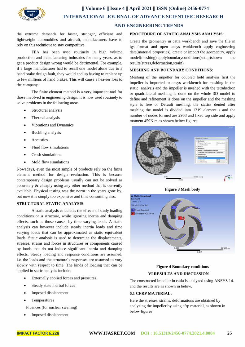
MESHING AND BOUNDARY CONDITIONS:
Meshing of the impeller for coupled field analysis first the
impeller is imported to ansys workbench for meshing in the
static analysis and the impeller is meshed with the tetrahedron
or quadrilateral meshing is done on the whole 3D model to
define and refinement is done on the impeller and the meshing
style is free or Default meshing. the statics denied after
meshing the model is divided into 1319 element s and the
number of nodes formed are 2968 and fixed top side and apply
moment 459N.m as shown below figures.
Figure 3 Mesh body
Figure 4 Boundary conditions
VI RESULTS AND DISCUSSION
The constructed impeller in catia is analyzed using ANSYS 14.
and the results are as shown in below.
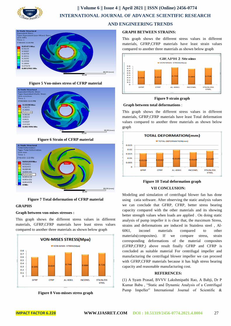
6.1 CFRP MATERIAL:
Here the stresses, strains, deformations are obtained by
analyzing the impeller by using cfrp material, as shown in
below figures
|| Volume 6 || Issue 4 || April 2021 || ISSN (Online) 2456-0774
INTERNATIONAL JOURNAL OF ADVANCE SCIENTIFIC RESEARCH
AND ENGINEERING TRENDS
IMPACT FACTOR 6.228 WWW.IJASRET.COM DOI : 10.51319/2456-0774.2021.4.0004 27
Figure 5 Von-mises stress of CFRP material
Figure 6 Strain of CFRP material
Figure 7 Total deformation of CFRP material
GRAPHS
Graph between von-mises stresses :
This graph shows the different stress values in different
materials, GFRP,CFRP materials have least stress values
compared to another three materials as shown below graph
Figure 8 Von-misses stress graph
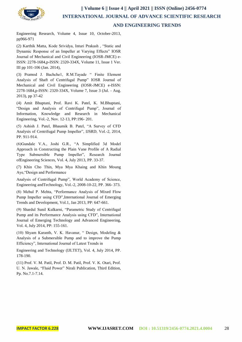
GRAPH BETWEEN STRAINS:
This graph shows the different stress values in different
materials, GFRP,CFRP materials have least strain values
compared to another three materials as shown below graph
Figure 9 strain graph
Graph between total deformations :
This graph shows the different stress values in different
materials, GFRP,CFRP materials have least Total deformation
values compared to another three materials as shown below
graph
Figure 10 Total deformation graph
VII CONCLUSION:
Modeling and simulation of centrifugal blower fan has done
using catia software. After observing the static analysis values
we can conclude that GFRP, CFRP, better stress bearing
capacity compared with the other materials and its showing
better strength values when loads are applied . On doing static
analysis of pump impeller it is clear that, the maximum Stress,
strains and deformations are induced in Stainless steel , Al-
6061, inconel materials compared to other
materials(composites). If we compare stress, strain
corresponding deformations of the material composites
(GFRP,CFRP,) above result finally GFRP and CFRP is
concluded as suitable material For centrifugal impeller and
manufacturing the centrifugal blower impeller we can proceed
with GFRP,CFRP materials because it has high stress bearing
capacity and reasonable manufacturing cost.
REFERENCES:
(1) A Syam Prasad, BVVV Lakshmipathi Rao, A Babji, Dr P
Kumar Babu , “Static and Dynamic Analysis of a Centrifugal
Pump Impeller” International Journal of Scientific &
|| Volume 6 || Issue 4 || April 2021 || ISSN (Online) 2456-0774
INTERNATIONAL JOURNAL OF ADVANCE SCIENTIFIC RESEARCH
AND ENGINEERING TRENDS
IMPACT FACTOR 6.228 WWW.IJASRET.COM DOI : 10.51319/2456-0774.2021.4.0004 28
Engineering Research, Volume 4, Issue 10, October-2013,
pp966-971
(2) Karthik Matta, Kode Srividya, Inturi Prakash , “Static and
Dynamic Response of an Impeller at Varying Effects” IOSR
Journal of Mechanical and Civil Engineering (IOSR-JMCE) e-
ISSN: 2278-1684,p-ISSN: 2320-334X, Volume 11, Issue 1 Ver.
III pp 101-106 (Jan. 2014),
(3) Pramod J. Bachche1, R.M.Tayade “ Finite Element
Analysis of Shaft of Centrifugal Pump” IOSR Journal of
Mechanical and Civil Engineering (IOSR-JMCE) e-ISSN:
2278-1684,p-ISSN: 2320-334X, Volume 7, Issue 3 (Jul. - Aug.
2013), pp 37-42
(4) Amit Bhuptani, Prof. Ravi K. Patel, K. M.Bhuptani,
“Design and Analysis of Centrifugal Pump”, Journal of
Information, Knowledge and Research in Mechanical
Engineering, Vol.-2, Nov. 12-13, PP:196- 201.
(5) Ashish J. Patel, Bhaumik B. Patel, “A Survey of CFD
Analysis of Centrifugal Pump Impeller”, IJSRD, Vol.-2, 2014,
PP. 911-914.
(6)Gundale V.A., Joshi G.R., “A Simplified 3d Model
Approach in Constructing the Plain Vane Profile of A Radial
Type Submersible Pump Impeller”, Research Journal
ofEngineering Sciences, Vol. 4, July 2013, PP. 33-37.
(7) Khin Cho Thin, Mya Mya Khaing and Khin Moung
Aye,“Design and Performance
Analysis of Centrifugal Pump”, World Academy of Science,
Engineering andTechnology, Vol.-2, 2008-10-22, PP. 366- 373.
(8) Mehul P. Mehta, “Performance Analysis of Mixed Flow
Pump Impeller using CFD”,International Journal of Emerging
Trends and Development, Vol.1, Jan 2013, PP: 647-661.
(9) Shardul Sunil Kulkarni, “Parametric Study of Centrifugal
Pump and its Performance Analysis using CFD”, International
Journal of Emerging Technology and Advanced Engineering,
Vol. 4, July 2014, PP: 155-161.
(10) Shyam Karanth, V. K. Havanur, “ Design, Modeling &
Analysis of a Submersible Pump and to improve the Pump
Efficiency”, International Journal of Latest Trends in
Engineering and Technology (IJLTET), Vol. 4, July 2014, PP.
178-190.
(11) Prof. V. M. Patil, Prof. D. M. Patil, Prof. V. K. Otari, Prof.
U. N. Jawale, “Fluid Power” Nirali Publication, Third Edition,
Pp. No.7.1-7.14.


![Indian Constitutional Law Review [ISSN: 2456-8325] Edition V …iclrq.in/editions/jul18/Art6.pdf · Indian Constitutional Law Review [ISSN: 2456-8325] Edition V [July 2018] Published](https://img.pdfslide.us/doc/110x75/5f81a2116ed8d010624d4b00/indian-constitutional-law-review-issn-2456-8325-edition-v-iclrqineditionsjul18art6pdf.jpg)


![Indian Constitutional Law Review [ISSN: 2456-8325] …iclrq.in/editions/jul18/Art3.pdfIndian Constitutional Law Review [ISSN: 2456-8325] Edition V [July 2018] Published by Agradoot](https://img.pdfslide.us/doc/110x75/5e757292f8b9e5405c52d8c6/indian-constitutional-law-review-issn-2456-8325-iclrqineditionsjul18art3pdf.jpg)