Embed Size (px)
Citation preview

www.upsd
irect.
com

INTRODUCTION Thank you for choosing our product. Our company is highly specialised in the development and production of uninterruptible power supplies (UPS). The UPS device described in this manual is a high quality product that has been carefully designed and manufactured to guarantee optimal performance. This manual contains detailed instructions for product use and installation. This manual must be stored in a safe place and CONSULTED BEFORE DEVICE USE for proper usage instructions as well as maximum performance from the device itself.
NOTE: Some images contained in this document are for information purposes only and may not faithfully demonstrate the parts of the product they represent
ENVIRONMENTAL PROTECTION Our company devotes abundant resources to analysing environmental aspects in the development of its products. All our products pursue the objectives defined in the environmental management system developed by the company in compliance with applicable standards. Hazardous materials such as CFCs, HCFCs or asbestos have not been used in this product. Packaging is composed of RECYCLABLE MATERIALS. Dispose of all material in compliance with applicable standards in the country in which the product is used. Refer to the following table to identify materials:
DESCRIPTION MATERIAL Pallet Wood
(FOR)
Package box Corrugated cardboard (PAP)
Protective bag High density polyethylene (PE-HD)
Adhesive buffers Low density polyethylene
(PE-HD) Bubble wrap
DISPOSING OF THE PRODUCT The UPS contains internal material which (in case of dismantling/disposal) are considered TOXIC AND HAZARDOUS WASTE, such as electronic circuit boards and batteries. Treat these materials according to the laws in force, contacting qualified centres. Proper disposal contributes to respect for the environment and human health.
© The reproduction of any part of this manual, even in part, is prohibited unless authorised by the Manufacturer.
The manufacturer reserves the right to change the product described at any time without prior notice for improvement purposes.
www.upsd
irect.
com

CONTENTS
PRESENTATION 6
MULTI SENTRY 60 – 80KVA 6
FRONT UPS VIEWS 7
UPS CONNECTIONS VIEW 9
UPS REAR VIEW 10
CONTROL PANEL VIEW 11
SEPARATE BYPASS INPUT (OPTIONAL) 12
INSTALLATION 13
INSTALLATION SET-UP 13
UPS STORAGE 13
PRELIMINARY INFORMATION 13
ELECTROMAGNETIC COMPATIBILITY 14
INSTALLATION ENVIRONMENT 14
REMOVING THE UPS FROM THE PALLET 15
CONTENT CHECK 16
UPS POSITIONING 16
ELECTRICAL CONNECTIONS 17
CONNECTION CABLES SECTION 17
ARRANGING CONNECTION CABLES 17
PRELIMINARY OPERATIONS FOR CONNECTION 18
CONNECTIONS TO MODELS WITH STANDARD BYPASS 19
CONNECTIONS TO MODELS WITH SEPARATE BYPASS 19
ELECTRICAL SYSTEM CONNECTION DIAGRAMS 20
PROTECTION DEVICES 23
SHORT-CIRCUIT PROTECTION 23
PROTECTION AGAINST BACK-FEED 23
INPUT LINE THERMAL MAGNETIC SWITCHES 23
BATTERY LINE 23
OUTPUT LINE FUSES/THERMAL MAGNETIC SWITCHES 24
DIFFERENTIAL 24
R.E.P.O. 25
EXTERNAL SYNC 25
AUXILIARY CONTACTS 26
EXTERNAL TEMPERATURE SENSOR 26
REMOTE PANEL 26
www.upsd
irect.
com
POWER SHARE AUXILIARY SOCKET 26
REMOTE MAINTENANCE BYPASS 27
USE 28
DESCRIPTION 28
FIRST START-UP AND ADDITIONAL SETTINGS 29
SWITCHING ON FROM THE MAINS 31
SWITCHING ON FROM THE BATTERY 31
SHUTDOWN 31
GRAPHIC DISPLAY 32
DISPLAY MENU 34
OPERATING MODE 35
MANUAL BYPASS (SWMB) 35
REDUNDANT AUXILIARY POWER ADAPTER FOR AUTOMATIC BYPASS 36
POWER WALK-IN 36
DERATING OF POWER FOR 200/208V NEUTRAL-PHASE LOADS 36
UPS CONFIGURATION 37
COMMUNICATION PORTS 39
RS232 AND USB CONNECTORS 39
COMMUNICATION SLOT 39
AS400 PORT 40
ACOUSTIC SIGNAL (BUZZER) 41
SOFTWARE 42
MONITORING AND CONTROL SOFTWARE 42
CONFIGURATION SOFTWARE 42
TROUBLESHOOTING 43
STATUS / ALARM CODES 47
TECHNICAL DATA 51
www.upsd
irect.
com

www.upsd
irect.
com

PRESENTATION
MULTI SENTRY 60 – 80KVA
MST 60 – 80 series UPS have been designed using currently available state of the art technology to ensure maximum performance. The use of new control boards based on multiprocessor architecture (DSP + P) and of special circuit solutions employing the latest generation of components has enabled us to achieve high performance such as:
ZERO IMPACT SOURCE: ensures low input distortion, power factor close to one and maximum compatibility with the generator
BATTERY CARE SYSTEM: allows custom handling of batteries for different topologies and continuous monitoring of the same, thus increasing efficiency and duration
SMART INVERTER: provides extraordinary efficiency even at low load rates and a stable output voltage and low distortion even in the most extreme operating conditions
www.upsd
irect.
com

FRONT UPS VIEWS
Control panel with graphic display
Wheels for UPS handling
Front door with lock Parking brakes
Ventilation grille
5
4
3
2
1
www.upsd
irect.
com

From left to right:
“COLD START” battery start-up button “R.E.P.O.” Remote Emergency Power Off “AS400” Contacts port “USB” communication port “RS232” communication port “UPS Parallel Board” housing (optional)
From left to right: “SWIN” Input switch “SWBYP” Separate bypass switch (optional) “QN” Switch for service personnel use only “SWMB” Manual bypass switch “SWOUT” Output switch
Slot for communication accessory boards Terminal cover panel
4
3
1 2
www.upsd
irect.
com

UPS CONNECTIONS VIEW
Removing the terminal cover panel to access the UPS terminal board:
BATT (+ N -) Power connections: External BATTERY BOX
INPUT (L1 L2 L3 N) Power connections: INPUT
BYPASS (L1 L2 L3 N) Power connections: SEPARATE BYPASS (optional)
OUTPUT (L1 L2 L3 N) Power connections: OUTPUT
PE Power connections: GROUND
A1 - A2 Connection for external synchronization signal
A3 - A4 Connection for remote auxiliary maintenance bypass
A5 - A6 Connection for remote auxiliary output switch
EXT BATT TEMP Connection for external battery temperature probe
www.upsd
irect.
com

UPS REAR VIEW
“Powershare Socket” housing (optional)
Power board fans
“MultiCOM 382 contacts board” accessory housing
Battery charger fan
4
1
3
2
www.upsd
irect.
com

CONTROL PANEL VIEW
Network operation LED Replace batteries LED
Battery operation LED ECO mode LED
Load on bypass LED Graphic display
Stand-by / alarm LED
F1, F2, F3, F4 = FUNCTION KEYS. Each key's task can be found on the lower part of the display and varies
according to menu.
www.upsd
irect.
com

SEPARATE BYPASS INPUT (OPTIONAL)
THE "DUALINPUT" UPS SERIES VERSION PRESENTS THE BYPASS LINE SEPARATE FROM THE INPUT LINE.
The UPS series with Separate Bypass allows a separate connection between the input line and the bypass line. The UPS output will be synchronized to the bypass line in such a way that there will not be any incorrect switching between push-pull voltages in the event of automatic bypass intervention or manual bypass (SWMB) closing.
www.upsd
irect.
com

INSTALLATION
INSTALLATION SET-UP
ALL OPERATIONS DESCRIBED IN THIS SECTION MUST BE PERFORMED BY QUALIFIED PERSONNEL ONLY.
Our Company assumes no liability for damages caused by incorrect connections or operations not contained in this manual.
UPS STORAGE
The storage site must meet the following requirements: Temperature: -15°-40°C (5°-104°F)
Degree of relative humidity: 95% max PRELIMINARY INFORMATION
UPS Models MST 60 MST 80
Nominal power 60kVA 80kVA
Operating temperature 0 - 40 °C
Max relative humidity in operation 90 % (without condensation)
Max installation height 1000 m at nominal power
(-1% power for every 100 m above 1000 m) max 4000 m
Dimensions L x P x A 500 x 850 X 1600 mm
Weight 190kg 200kg
Power loss at nominal resistive load (pf=0.9) and with charged batteries
(1)
2.61 kW 2245 kcal/h
8910 B.T.U./h
3.65 kW 3140 kcal/h
12460 B.T.U./h
Power loss at nominal distorting load (pf=0.7) and with charged batteries
(1)
2.41 kW 2070 kcal/h
8220 B.T.U./h
3.12 kW 2680 kcal/h
10640 B.T.U./h
Installation site fan flow rate for heat removal (2)
1400mc/h 2000 mc/h
Current dispersed to ground (3)
< 100 mA
Degree of protection IP20
Cable input at bottom rear
(1) 3.97 B.T.U./h = 1 kcal/h
(2) Use the following formula to calculate air flow: Q [mc/h] = 3.1 x Pdiss [kcal/h] / (ta - te) [°C]
Pdiss is power dissipation expressed in kcal/h in the installation site for all installed equipment.
ta= room temperature, te=external temperature. Increase the value derived by 10% to account for losses. An example of flow is shown in the table, with (ta - te)=5°C and with nominal resistive load (pf=0.9).
(Note: This formula is applicable if ta>te; otherwise, installation requires an air conditioner).
(3) The load dispersion current is added to that of the UPS on the ground protection conductor.
www.upsd
irect.
com

ELECTROMAGNETIC COMPATIBILITY
This UPS complies with applicable EMC (Category C3). ATTENTION: This product is designed for second environment* commercial and industrial applications - it may be necessary during installation to introduce certain restrictions and take additional measures to prevent disturbances. Connection to USB and RS232 connectors must be made with the supplied cables or, however, with shielded cables that are no longer than 3 metres. (*) Type of environment defined in EMC regulations
INSTALLATION ENVIRONMENT
When selecting the installation site of the UPS and any Battery Boxes, observe the following notes:
avoid dusty environments
ensure that flooring is flat and able to sustain the weight of the UPS (and Battery Boxes)
avoid environments that are too narrow which might prevent normal maintenance operations
relative humidity must not exceed 90%, without condensation
verify that the room temperature, with the UPS in operation, is maintained between 0 and 40°C
The UPS is able to operate at a temperature between 0 and 40°C. The recommended operating temperature for the UPS and the batteries is between 20 and 25°C. The actual operating life of the batteries is 5 years on average at an operating temperature of 20°C. If the operating temperature reaches 30°C, the operating life is halved.
avoid positioning the UPS in places which are exposed to direct sunlight or to hot air To maintain installation room temperature in the above indicated range, waste heat disposal should be provided for (the value of kW/kcal/h/ B.T.U /h dissipated by the UPS is shown in the table on the previous page). Methods which can be used include:
natural ventilation
forced ventilation, recommended if the external temperature is lower (e.g. 20°C) than the temperature at which you want to operate the UPS and/or the Battery Box (e.g. 25°C)
air conditioning system, recommended if the external temperature is higher (e.g. 30°C) than the temperature at which you want to operate the UPS and/or the Battery Box (e.g. 25°C)
www.upsd
irect.
com

REMOVING THE UPS FROM THE PALLET
ATTENTION: FOLLOW THE INSTRUCTIONS BELOW TO AVOID PERSONAL INJURY AND/OR EQUIPMENT DAMAGE.
SOME OF THE FOLLOWING OPERATIONS REQUIRE THE INTERVENTION OF TWO PEOPLE
A
AA
A
B
B
Cut straps and remove from the cardboard box. Remove the packaging material.
Remove the accessories container. NOTE: the accessories box may be located inside the packaging or behind the UPS door.
Remove the 2 brackets fastening the UPS to the pallet, unscrewing the type A and B screws.
A A
AA
The previously removed brackets can also to be used as slides. Fasten the slides to the pallet with the use of type A screws, taking care to align the two wheels.
If necessary, unblock the front wheel brakes Ensure that the door is fully closed. ATTENTION: it is advisable to bring the UPS down by pushing from the rear, using great care and accompanying it
as it moves down. Given the weight of the equipment, this requires the work of two people. NOTE: retain all packaging materials for future use
www.upsd
irect.
com

CONTENT CHECK
It is first necessary to check the contents after the packaging has been opened: steel slide, warranty card, instructions manuals, safety manual, inspection certificate, serial connection cable, keys for door lock.
UPS POSITIONING
When positioning, take into account that:
the wheels are only to be used for accurate positioning, so for short trips
plastic parts and the door are not able to act as pushing points or handles
you will need to ensure at least enough free space in front of the equipment to allow for start/stop operations and maintenance ( 1.5 m )
the upper part should be at least 50cm from the ceiling to allow for maintenance operations
the rear of the UPS must be placed at least 30 cm from the wall for proper air flow blown from air vents
no objects should rest on the upper part of the UPS After positioning, block the device by means of the front wheel brakes (see “Removing the pallet").
In earthquake zones or on mobile systems, it is possible to reuse the brackets for pallet fastening (slides) to anchor the UPS to the floor (see figure below). These brackets are not necessary in normal conditions.
www.upsd
irect.
com

ELECTRICAL CONNECTIONS
CONNECTION CABLES SECTION
Refer to the following table for the sizing of input, output and battery cables:
Cables section (mm2) (1)
INPUT network / separate bypass (optional) OUTPUT EXTERNAL BATTERY (2)
kVA PE L1/L2/L3 N (3) PE L1/L2/L3 N (3) PE +/- N
60 16 35 35 16 35 35 16 50 50
80 25 50 50 25 50 50 25 70 70 (1) The sections contained in the table refer to a maximum length of 10 m (cable type N07V-K in clear air) (2) The maximum length of the connection cables to the Battery Box is 10 metres (3) In the case of non-linear loads, oversize neutral line N by 1.7 times the phase line
Note: the maximum section of the cables that can be inserted in the terminal board is equal to 95 mm2 (flexible and rigid cables)
ARRANGING CONNECTION CABLES
It is advisable to wire the power cables routing them from the rear, under the UPS to the front of the machine, bringing them back in the terminal area as follows:
At the bottom of the units is a holed bar that can be used for a steady anchor for the cables by means of appropriately sized clamps. Notes:
- Clasp the clamps only after having tightened the cables in their relative power terminals. - Preform the cables so that they are not forced into the power terminals when the clamp is tightened.
www.upsd
irect.
com

PRELIMINARY OPERATIONS FOR CONNECTION
The following operations are to be performed with the UPS disconnected from the power mains, off and with all equipment switches open. Before making the connection, open all machine switches and verify that the UPS is completely isolated from power sources: battery and AC power line. In particular, check that:
- the UPS input line is completely disconnected
- the external UPS battery line switch/fuses are open
- all UPS switches: SWIN, SWBYP, SWOUT and SWMB in the open position
- check with a millimetre that there are no dangerous voltages
The first connection should be that of the protective conductor (ground cable) to be connected to the PE marked screw. The UPS should work with ground system connection.
The input Neutral must always be connected.
Do not connect the output neutral with the input neutral.
ATTENTION: a three-phase four-wire distribution system is required. The standard UPS version must be connected to a 3 Phase + Neutral + PE (ground protection) TT, TN or IT type power line. Comply with phase rotation TRANSFORMER BOXES (optional) are available to convert distribution systems from 3-wire to 4-wire.
ATTENTION: in the event of non-linear three-phase loads, the Neutral conductor (N) current can reach a value up to 1.7 times that of the phase current. Properly size the Input/output Neutral line keeping this fact in mind.
Carefully read instructions contained in the Battery Box manual before connecting batteries.
Check that battery voltage is the same as allowed by the UPS (consult the Battery Box data plate and the UPS manual)
ATTENTION: the maximum length of the connection cables to the Battery Box is 10 metres
www.upsd
irect.
com

CONNECTIONS TO MODELS WITH STANDARD BYPASS
Follow the instructions below in order: open the door remove the terminal cover panel positioned under the switches (see "Front UPS views" ) connect the protective conductor (ground cable) to the PE marked screw. connect the input, output and battery cables to the terminal board, observing the positions and polarities indicated in
the figure below
Note: connection of the protective conductor (ground cable ) must be made through an eyelet terminal with an M6 screw Once installation operations have been completed and connections verified (see paragraph "First start-up and initial settings"), restore the terminal cover panel and close the door. CONNECTIONS TO MODELS WITH SEPARATE BYPASS
Follow the instructions below in order: open the door remove the terminal cover panel positioned under the switches (see "Front UPS views" ) connect the protective conductor (ground cable) to the PE marked screw. connect the input, bypass, output and battery cables to the terminal board, observing the positions and polarities
indicated in the figure below
Note: connection of the protective conductor (ground cable ) must be made through an eyelet terminal with an M6 screw
The input and bypass Neutral must always be connected.
The input and bypass lines must be connected to the same potential as of the Neutral.
Do not connect the output neutral with the input or bypass neutral.
Once installation operations have been completed and connections verified (see paragraph "First start-up and initial settings"), restore the terminal cover panel and close the door.
www.upsd
irect.
com

ELECTRICAL SYSTEM CONNECTION DIAGRAMS
UPS without neutral connectivity variation
UPS with galvanic input insulation
UPS with galvanic output insulation
www.upsd
irect.
com

UPS without neutral connectivity variation and with separate bypass input
UPS with galvanic input insulation and with separate bypass input
UPS with galvanic output insulation and with separate bypass input
www.upsd
irect.
com

Separate bypass on separate lines: if the separate bypass option is present, all protective devices will have to be placed both on the main supply line and on the line dedicated to the bypass. Note: the input line and bypass line neutral are shared inside the device; therefore, they will have to be connected to the same potential. If the two power supplies are different, you must use an isolation transformer on one of the inputs.
UPS without neutral connectivity variation and with separate bypass input connected on an independent power line
UPS with separate bypass input connected on an independent power line and with galvanic input insulation
UPS with separate bypass input connected on an independent power line and with galvanic output insulation
www.upsd
irect.
com

PROTECTION DEVICES
SHORT-CIRCUIT PROTECTION
In the presence of a fault on the load, the UPS limits the value and duration of the output current (short circuit current) for protection. These values are also functions of unit status at the time of the fault. Two different cases can be distinguished:
UPS in NORMAL OPERATION: load is switched instantly on the bypass line (UPS 60kVA I2t=110000A2s; UPS 80kVA I2t=110000A2s): the input line is connected to the output without any internal protection (blocked after t>0.5s)
UPS in BATTERY-LED OPERATION: The UPS protects itself by supplying a current of about 1.5 times the nominal current in output for 0.5s, switching itself off after this amount of time
PROTECTION AGAINST BACK-FEED
The UPS is equipped with internal protection against backfeed via internal metal separation devices (Inverter contactor, see “UPS block diagram"). INPUT LINE THERMAL MAGNETIC SWITCHES
When setting the power supply line upstream of the UPS, install a thermal magnetic switch with trip curve C (or D depending on the type of load) as indicated in the following table:
Automatic external AC protections *
Mod. UPS Network input Separate bypass input (optional)
60kVA 100A 100A
80kVA 125A 125A
* In the case of non-linear loads, properly oversize neutral line N after on-site assessment
If the protection device upstream to the UPS interrupts the neutral conductor, all phase conductors must also be interrupted at the same time (4-pole switch).
BATTERY LINE
Surge protector and a cut-off device must be provided on the UPS external battery line.
The size and type of fuses must be selected on the basis of the capacity of the installed battery box, referring to the table below.
External DC protections
Mod. UPS Fuse type Fuse size [ A ]
60kVA gl / gG 2 x capacity in Ah of the battery up to max 150A
aR 2.5 x capacity in Ah of the battery up to max 150A
80kVA gl / gG 2 x capacity in Ah of the battery up to max 200A
aR 2.5 x capacity in Ah of the battery up to max 200A
Example: the following fuses can be used with UPS 60kVA and 65Ah batteries: 125A (130A) gl/gG or 150A type aR
Ensure that the UPS has been fully switched off before handling the external UPS battery line switch/fuses
www.upsd
irect.
com
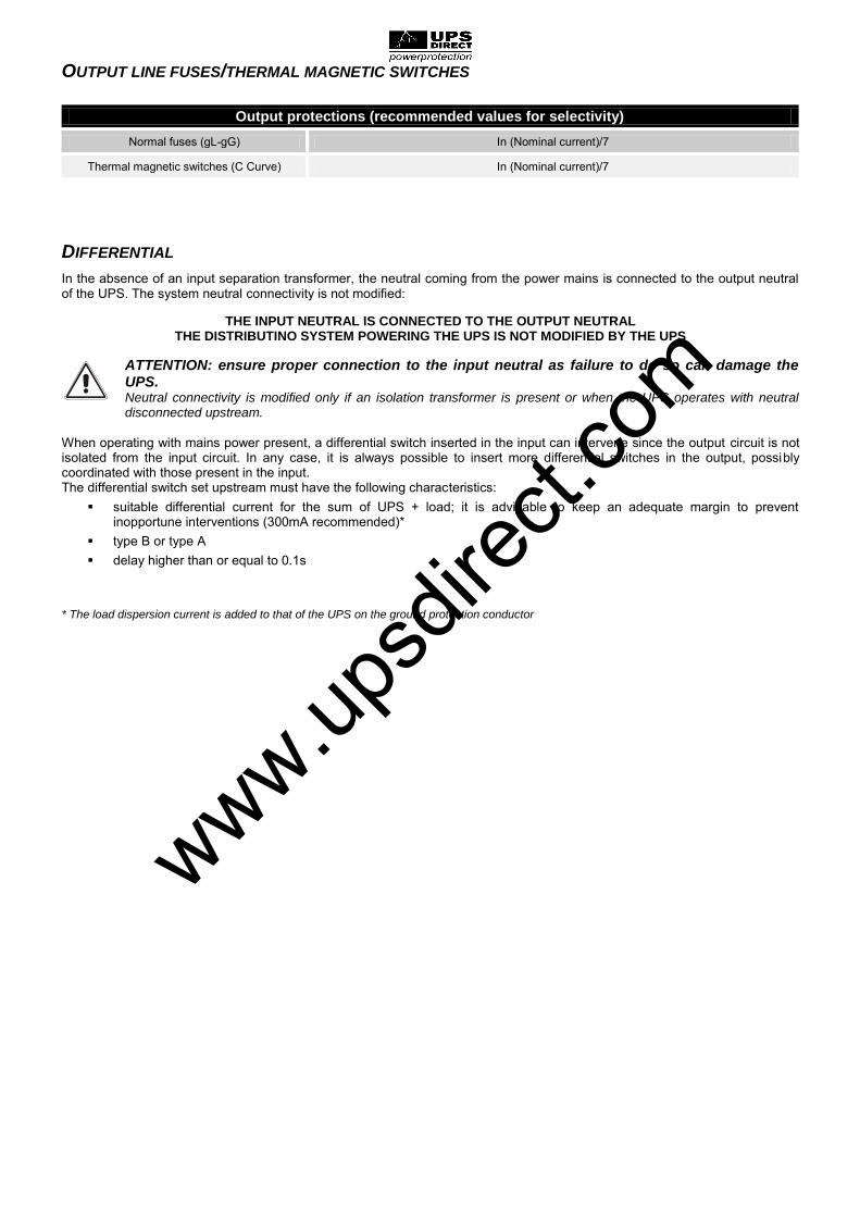
OUTPUT LINE FUSES/THERMAL MAGNETIC SWITCHES
Output protections (recommended values for selectivity)
Normal fuses (gL-gG) In (Nominal current)/7
Thermal magnetic switches (C Curve) In (Nominal current)/7
DIFFERENTIAL
In the absence of an input separation transformer, the neutral coming from the power mains is connected to the output neutral of the UPS. The system neutral connectivity is not modified:
THE INPUT NEUTRAL IS CONNECTED TO THE OUTPUT NEUTRAL THE DISTRIBUTINO SYSTEM POWERING THE UPS IS NOT MODIFIED BY THE UPS
ATTENTION: ensure proper connection to the input neutral as failure to do so can damage the UPS. Neutral connectivity is modified only if an isolation transformer is present or when the UPS operates with neutral disconnected upstream.
When operating with mains power present, a differential switch inserted in the input can intervene since the output circuit is not isolated from the input circuit. In any case, it is always possible to insert more differential switches in the output, possibly coordinated with those present in the input. The differential switch set upstream must have the following characteristics:
suitable differential current for the sum of UPS + load; it is advisable to keep an adequate margin to prevent inopportune interventions (300mA recommended)*
type B or type A delay higher than or equal to 0.1s
* The load dispersion current is added to that of the UPS on the ground protection conductor
www.upsd
irect.
com

R.E.P.O.
This isolated input can be used to remotely switch off the UPS in case of emergency. The UPS is supplied with "Remote Emergency Power Off" (R.E.P.O.) terminals short-circuited by a jumper (see "Front UPS Views"). To manage emergency shutdown, replace the jumper with the selected normally closed stop device contact. Connect using double insulation wiring. In case of an emergency, the stop device opens the R.E.P.O. control and the UPS goes into stand-by mode (all power stages off) and the load is completely disconnected. The R.E.P.O. circuit is self-powered with SELV circuits. Therefore, an external voltage supply is not required. When closed (normal condition), a current of 15mA max circulates.
EXTERNAL SYNC
This non-isolated input is used to synchronize the inverter output with a suitable signal coming from an external source. To install:
use an isolation transformer with isolated single-phase output (SELV) within range 12-24V AC with 0.5VA power connect the transformer primary to the external synchronization source, respecting the polarity indicated in the
following image connect the transformer secondary to terminals A1-A2 “EXTERNAL SYNC" (see "UPS connections view" ) by means
of a double insulation cable with 1 mm2 section. Attention: respect polarisation as indicated in the following image:
A special optional kit is available for external synchronization connection.
After installation, enable this option by means of the configuration software. www.upsd
irect.
com

AUXILIARY CONTACTS
Terminals for connecting auxiliary contacts of the remote maintenance and remote output bypass switches are available in the UPS connection zone. These are identified, respectively, by the words “SERVICE BYPASS” and “AUX SWOUT”. For installation, refer to paragraphs “UPS connections view” and “Remote maintenance bypass” A3-A4 SERVICE BYPASS
Before connecting, remove the pre-assembled jumper When the remote maintenance bypass switch is closed, the relative auxiliary contact should open
A5-A6 AUX SWOUT
When the remote output switch is closed, the relative auxiliary contact should open Use a double insulation cable with 1 mm2 section for terminal connection ATTENTION: in the case of parallel systems, each single UPS must have its own independent external auxiliary contact
EXTERNAL TEMPERATURE SENSOR
This NON-ISOLATED input is used to detect temperature inside a remote Battery Box.
Only use the special kit (optional) supplied by the manufacturer: any uses which do not conform to specifications may cause malfunction or equipment breakage.
For installation, connect the cable contained in the special kit (optional) to the "EXT BATT TEMP" connector (see "UPS connections view") following instructions contained in the relative manual. After installation, enable this external temperature measuring function by means of the configuration software.
REMOTE PANEL
The remote panel (optional) allows you to monitor the UPS from a distance and thus have a detailed, real-time overview of machine status. Using this type of device, network, output, battery measurements etc. can be viewed and any alarms detected. For details related to use and connections, refer to the appropriate manual.
POWER SHARE AUXILIARY SOCKET
Programmable output socket (optional) which allows automatic disconnection of the load applied to it under certain operating conditions. Events that determine automatic disconnection of the Powershare socket can be selected by the user through the configuration software. It is possible, for example, to select detachment after a certain period of battery operation, or when the pre-alarm threshold for battery discharge has been reached, or when an overload occurs.
Notes regarding safety: if the output switch (SWOUT) is opened while the UPS is on, the sockets remain powered.
If a manual bypass switch (SWMB) is inserted, the output switch (SWOUT) is opened and the UPS switches off and the sockets will no longer be powered.
www.upsd
irect.
com

REMOTE MAINTENANCE BYPASS
Attention: carefully read the “Manual bypass (SWMB)” paragraph A maintenance bypass (manual bypass) can be installed additionally on a peripheral electrical board (see following diagram). This allows, for example, UPS replacement without interrupting power to the load.
The "SERVICE BYPASS" (see "UPS connections view") terminal absolutely must be connected to the auxiliary contact of the REMOTE MAINTENANCE BYPASS SWITCH (3). When this switch closes, an auxiliary contact signalling insertion of the remote bypass to the UPS must open. Failure to perform this connection can cause power cut-off to the load and UPS damage.
Use switches and power cables suitable for UPS currents. Use a double insulation cable with a 1mm2 section for connecting "SERVICE BYPASS" and "AUX SWOUT"
terminals to relative REMOTE MAINTENANCE BYPASS (3) and OUTPUT (2) switch auxiliary contacts. Verify compatibility between the "Remote maintenance bypass" and neutral connectivity of the system.
REMOTE MAINTENANCE BYPASS INSTALLATION DIAGRAM
Peripheral electrical board
Internal UPS connections
Electrical board INPUT SWITCH
Electrical board OUTPUT SWITCH: equipped with normally closed auxiliary contact (advanced)
Electrical board REMOTE MAINTENANCE BYPASS SWITCH: equipped with normally closed auxiliary contact (advanced)
www.upsd
irect.
com

USE
DESCRIPTION
The purpose of the UPS is to ensure perfect supply voltage to the equipment connected to it, both in the presence and absence of mains power. Once connected and powered, the UPS generates alternating sinusoidal voltage with stable range and frequency, regardless of sudden changes and/or variations on the mains power. As long as the UPS draws power from the mains, the batteries are kept charged under the control of a multiprocessor board. This board constantly monitors mains voltage range and frequency and the range and frequency of voltage generated by the inverter, applied load, internal temperature and battery efficiency conditions. The following is a block diagram of the UPS which describes the individual components that it is composed of.
UPS block diagram IMPORTANT: Our UPS have been designed and built for long-term duration even in the most demanding operating conditions. Please remember however that these are electrical power devices and, as such, they require periodic inspections. In addition, some components inevitably have their own life cycles and, therefore, they must be checked periodically and replaced if necessary: in particular, the batteries, fans and, in some cases, the electrolytic capacitors. It is therefore recommended to implement a preventive maintenance programme, to be entrusted to manufacturer authorised, qualified personnel. Our Technical Assistance is at your service to propose different preventive maintenance options tailored to your specific needs.
Inverter contactor
Input contactor
www.upsd
irect.
com

FIRST START-UP AND ADDITIONAL SETTINGS
ATTENTION: the QN switch is for Service personnel use only and must remain closed with its safety lock.
Only the following switches can be handled: SWIN, SWBYP (if present), SWOUT, external UPS battery line switch and, necessary, SWMB (see paragraph “Manual bypass (SWMB)”)
Visual connection inspection
Check that all connections have carefully been made according to the paragraph "Electrical connections." Check that all switches are open (except for the QN switch, locked in the closed position).
Closing the external UPS battery line switch/fuses After having checked proper connection polarity, close the external UPS battery line switch/fuses
Attention: any connection made not in compliance with instructions stated in paragraph "Electrical connections" may have damaged the battery fuses and other protections; in this case, call for assistance to avoid further damage to the UPS.
UPS Power Close protections upstream to the UPS.
Closing the SWMB Manual bypass switch
Close the SWMB manual bypass switch and check that output voltage is present. Re-open the SWMB switch.
Closing input switches
Close the SWIN and SWBYP input switches (if present).
SERVICE PERSONNEL
ONLY
www.upsd
irect.
com

Wait a few seconds after SWIN closing. Check that the display switches on and that the UPS is set to "STAND-BY" mode.
Follow the instructions below if a message indicating an erred phase cycle direction appears on the display:
check if the error code corresponds to the input or the bypass (only for separate bypass models)
open all switches and input and output
wait for the display to switch off
open the external UPS battery line switches/fuses
open all protections upstream to the UPS
remove the terminal cover protective panel
correct the position of cables relative to the signalled terminal board so that they follow phase cycle direction
re-close the terminal cover protective panel
repeat the preliminary operations contained on the previous page
Refer to “Graphic display” and “Display menu” paragraphs for control panel management
Setting the nominal battery capacity
ATTENTION: you must configure the UPS to set the correct values of total nominal capacity of the battery. This operation must be performed by means of the configuration software reserved for Service personnel only.
From the main menu, press to enter into the start menu. When asked to confirm, select “YES”, press to confirm and wait a few seconds. Verify that the UPS is set to status with the inverter-powered load.
Closing the output switch SWOUT
Open the input switch (SWIN) and wait a few seconds. Verify that the UPS is set to battery operation and that the load is still being properly powered. You should hear a beep every 7 sec.
Close the input switch (SWIN) and wait a few seconds. Verify that the UPS is no longer in battery operation and that the load is being properly powered from the inverter.
To set the Date and Hour, access menu 8.6.7 (see "Display menu") from the main menu. Use the arrow keys (↑↓) to set the desired value and, finally, press the confirm key ( ) to move to the next field. To save the new settings, return to the previous menu by pressing the key.
www.upsd
irect.
com

SWITCHING ON FROM THE MAINS
Close the SWIN and SWBYP input switches (if present) and leave the SWMB manual bypass switch open. After a few seconds, the UPS will switch on and the "Stand-by / alarm" LED will flash: the UPS is now in stand-by status.
Press to access the start menu. When asked to confirm, select “YES” and press again to confirm. All the LEDs around the display will light up for about 1 sec. and a beep will be emitted. The start sequence is completed when the UPS is set to status with the inverter-powered load.
SWITCHING ON FROM THE BATTERY
Ensure that the external UPS battery line switch/fuses are closed
Keep the "Cold Start" (located behind the door) key pressed for about 5 sec. The UPS will switch on and the display will turn on.
Press to access the start menu. When asked to confirm, select “YES” and press again to confirm. All the LEDs around the display will light up for about 1 sec. and the buzzer will begin to emit a beep every 7 sec. The start sequence is completed when the UPS is set to battery operation status.
Note: if the sequence described above is not performed within 1 min., the UPS will shut itself off to avoid unnecessary running down the battery
SHUTDOWN
From the main menu, select the item “SHUTDOWN” and press to access the sub-menu. Then select the “YES - CONFIRM” option and press . The UPS will be set to stand-by status and the load will no longer be powered. To completely switch off the UPS, open the SWIN and SWBYP input switches (if present), wait a few seconds while the display turns off and, finally, open the external UPS battery line switch/fuses.
www.upsd
irect.
com

GRAPHIC DISPLAY
At the centre of the control panel is a wide graphic display for a constant detailed, real-time overview of UPS status. The first page is a schematic view of UPS operating status:
Input Line Battery Charger Line
PFC Converter Battery Line
Inverter % Load
Inverter Output Line % Battery Charge
Automatic Static Bypass
The diagram shows the status of the three power logical modules (PFC Converter, Inverter, Automatic Static Bypass). Each module can take on one of the following status types:
Module Off
Module on in normal operating mode
Module alarm or block
The following symbols show the power flow to and from the batteries (uncharged/charged) and the status of input and inverter contacts:
Module Off
Module on in normal operating mode
www.upsd
irect.
com

In addition, the user can switch the UPS on/Off directly from the control panel, consult network, output, battery measurements, etc.(1) and make the main machine settings. The display is sub-divided into four main zones, each with its own specific role.
Graphic display sample screens (screens for demonstration purposes; situations depicted may differ from reality)
GENERAL INFORMATION
Part of the display where the set date and hour are permanently shown and, depending on the screen, the page number or title of the menu that is active in that moment.
DATA VIEWING / MENU NAVIGATION
Main part of the display reserved for viewing of UPS measurements (constantly updated in real time) as well as to the consultation of various menus that can be selected by the user by means of the related function keys. Once the desired menu has been selected, this part of the display will show one or more pages containing all data relative to the selected menu.
UPS STATUS / ERRORS - FAULTS
UPS operation status display area. The first row is always active and constantly displays UPS status in real time. The second is activated only in the presence of a UPS error and/or fault and shows the type of detected error/fault. A code corresponding to the event in progress is shown to the right of each row.
KEYS FUNCTION
Area divided into four boxes, each relative to the underlying function key. Depending on the menu that is active in that moment, the display shows the function of the corresponding key in the related box.
Key symbols
To enter into the main menu
To return to the previous menu or display
To scroll the various selectable items inside a menu or to pass from one page to another during data display
To confirm selection
To temporarily silence the buzzer (keep press for at least 0.5 sec.). To cancel a programmed start-up/shutdown(keep press for at least 2 sec.).
(1) The accuracy of the measurements is: 1% for voltage measurements, 3% for current measurements,0.1% for frequency measurements.
The indication of remaining battery time is an ESTIMATE, and is not to be considered an instrument of absolute measurement.
www.upsd
irect.
com

DISPLAY MENU
www.upsd
irect.
com

OPERATING MODE
The mode that ensures the most load protection is the ON LINE mode, where power for the load undergoes a couple conversion and is reconstructed at output in a perfectly sinusoidal way, with frequency and voltage fixed by the precise digital control of the DSP independently from the input (V.F.I.). * It is possible to select the following modes next to the traditional double conversion ON LINE operating mode:
ECO (LINE INTERACTIVE)
SMART (SMART ACTIVE)
STBYOFF (STAND-BY OFF) In order to optimise performance, the load is normally powered by the bypass in ECO mode (any disturbances presented on the mains can have repercussions on the load). In the case of no mains or simply output from expected tolerances, the UPS will transfer to normal double conversation ON LINE operation. Approximately 5 minutes after the mains tolerances are restored, the load is automatically switched over to bypass.
In the event that the user is not able to decide which operating mode is best for use (between ON LINE and ECO), he can entrust the choice to SMART ACTIVE mode. Based on statistics detected regarding power mains quality, the UPS decides on its own which mode to configure.
Finally, in STAND-BY OFF mode, operation is configured as back-up: in the presence of mains, the load is not powered, during a black-out, the load is powered by an inverter by means of batteries, to then be switched off again upon mains return. Intervention time is less than 0.5 sec. * Value rms of output voltage is fixed by the precise control of the DSP independently from input voltage, while the frequency of output
voltage is synchronized (within a tolerance to be set by the user) with that of the input for bypass use. Outside of this tolerance, the UPS desynchronizes, bringing itself to the nominal frequency and bypass can no longer be used (free running mode).
MANUAL BYPASS (SWMB)
ATTENTION: Contact a service centre should any malfunctions be detected. UPS maintenance can only be performed by skilled personnel who have been trained by the manufacturer. ATTENTION: dangerous voltages even with the input, bypass, output and battery open switches can be present inside equipment. Removal of UPS closing panels by unqualified personnel is dangerous and can cause harm to the operator, equipment and utilities connected to it.
Operations to be performed in order for setting the UPS in "Manual bypass" status without interrupting power to the load:
Attention: if the UPS is in battery operation, manual bypass insertion may cut off power to the load.
Close the SWMB manual bypass switch located behind the door: in this way, the input is short-circuited with the output.
Open the SWIN input, SWBYP bypass (if present) and SWOUT output switches. Open the external UPS battery line switch/fuses. The control panel will switch off after a few seconds. In this operating mode, any disturbance or blackouts on the UPS power line will have repercussions on the powered equipment (the UPS is no longer active and the load is connected directly to the mains). In addition, the auxiliary "Power share" (if present) socket will no longer be powered (see paragraph "Auxiliary socket (power share)").
Operations to be performed to start up the UPS in "Manual bypass" status without cutting off power to the load: (to be performed only when no faults or malfunctions have been detected):
Close the SWIN input, SWBYP bypass (if present) and SWOUT output and the external UPS battery line switches. The control panel will reactivate. Restart the UPS from the "SYSTEM ON" menu. Wait for the sequence to be completed.
Open the SWMB manual bypass switch: the UPS will restart normal operation.
www.upsd
irect.
com

REDUNDANT AUXILIARY POWER ADAPTER FOR AUTOMATIC BYPASS
The UPS is equipped with a redundant auxiliary power adapter which permits operation on the automatic bypass even in the event of main auxiliary power faults. In the event of a UPS fault, which also can cause breakage of the main auxiliary power, the load remains powered by means of the automatic bypass. ATTENTION: the multiprocessor board and control panel are not powered in this mode; therefore, the LEDs and displays are off.
In this emergency condition, any disturbances present on the input line have repercussions on the load.
POWER WALK-IN
The UPS is equipped with a Power Walk-In mode which can be activated and configured via configuration software. When this mode is enabled, once the mains power is restored (after a period of autonomy), the UPS begins absorbing from it again progressively so as not to threaten (due to the peak) for any generator group that may be installed upstream. The duration of the transition can be set from 0 to 125 seconds. The default value is 10 seconds (when this function is active). During the transition, the power required is drawn partly from the batteries and partly from the mains while maintaining sinusoidal absorption. The battery charger is switched back on only after the transition is complete
DERATING OF POWER FOR 200/208V NEUTRAL-PHASE LOADS
In the event in which output voltage is set at 200V or 208V NEUTRAL-PHASE, the maximum power that can be supplied by the UPS undergoes derating with respect to the nominal power, as demonstrated in the following graph:
www.upsd
irect.
com
UPS CONFIGURATION
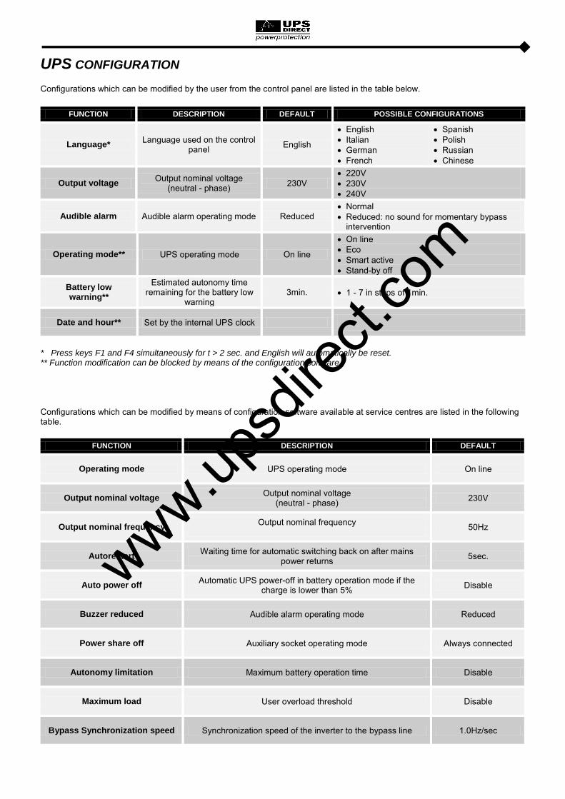
Configurations which can be modified by the user from the control panel are listed in the table below.
FUNCTION DESCRIPTION DEFAULT POSSIBLE CONFIGURATIONS
Language* Language used on the control
panel English
English Italian German French
Spanish Polish Russian Chinese
Output voltage Output nominal voltage
(neutral - phase) 230V 220V 230V 240V
Audible alarm Audible alarm operating mode Reduced Normal Reduced: no sound for momentary bypass
intervention
Operating mode** UPS operating mode On line
On line Eco Smart active Stand-by off
Battery low warning**
Estimated autonomy time remaining for the battery low
warning 3min. 1 - 7 in steps of 1min.
Date and hour** Set by the internal UPS clock
* Press keys F1 and F4 simultaneously for t > 2 sec. and English will automatically be reset. ** Function modification can be blocked by means of the configuration software. Configurations which can be modified by means of configuration software available at service centres are listed in the following table.
FUNCTION DESCRIPTION DEFAULT
Operating mode UPS operating mode On line
Output nominal voltage Output nominal voltage
(neutral - phase) 230V
Output nominal frequency Output nominal frequency
50Hz
Autorestart Waiting time for automatic switching back on after mains
power returns 5sec.
Auto power off Automatic UPS power-off in battery operation mode if the
charge is lower than 5% Disable
Buzzer reduced Audible alarm operating mode Reduced
Power share off Auxiliary socket operating mode Always connected
Autonomy limitation Maximum battery operation time Disable
Maximum load User overload threshold Disable
Bypass Synchronization speed Synchronization speed of the inverter to the bypass line 1.0Hz/sec
www.upsd
irect.
com

FUNCTION DESCRIPTION DEFAULT
External synchronization Synchronization source of inverter output From bypass line
External temperature Activation of the external temperature probe Disable
Bypass mode Mode of use of the bypass line Enabled / High sensibility
Bypass active in stand-by Load powering from bypass with UPS in stand-by Disabled (load NOT powered)
Bypass frequency tolerance Range permitted for the input frequency for switching to the
bypass and for output synchronization ±5%
Bypass min.-max. threshold Permitted voltage range for switching to the bypass Low: 180V
High: 264V
Eco mode sensibility Intervention sensitivity during ECO mode operation Normal
Eco mode min.-max. threshold
Permitted voltage range for ECO mode operation Low: 200V
High: 253V
UPS without battery Operating mode without batteries (for frequency
converters/stabilisers) Operation with
batteries
Battery low time Estimated autonomy time remaining for the battery low
warning 3min.
Automatic battery test Interval of time for the automatic battery test 40 hours
Parallel common battery Parallel system with single battery (common between all
system UPS) Disable
Internal battery capacity Nominal internal battery capacity Variable depending on UPS model and
size
External battery capacity Nominal external battery capacity 7Ah for UPS without
internal batteries, 0Ah in all other cases
Battery charging algorithm Battery algorithm and charging threshold Two levels
Battery recharging current Percentage of charging current compared to nominal battery
capacity 12%
www.up
sdire
ct.co
m

COMMUNICATION PORTS
The following communication ports are present on the upper part of the UPS behind the door (see UPS Views):
Serial port, available with RS232 and USB connectors. NOTE: use of one connector automatically excludes the other
Expansion slot for additional COMMUNICATION SLOT communication boards
AS400 port
It is also possible to install an optional MultiCOM 382 contact board (4 programmable contacts, 250V AC, 3A) on the rear of the UPS RS232 AND USB CONNECTORS
RS232 CONNECTOR USB CONNECTOR
PIN # NAME TYPE SIGNALS PIN # SIGNALS
1 IN 1 VBUS
2 TX OUT TX serial line 2 D-
3 RX IN RX serial line 3 D+
4 4 GND
5 GND POWER
6 OUT
7
8 +15V POWER Isolated power 15V±5% 80mA max
9 WKATX OUT ATX power adapter activator COMMUNICATION SLOT
The UPS is supplied with two expansion slots for optional communication cards that allow device dialogue using the main communication standards (see "Front UPS views"). Some examples:
Second RS232 port
Serial duplicator
Ethernet network card with TCP/IP, HTTP and SNMP protocols
RS232 + RS485 ports with JBUS / MODBUS protocol
Refer to the website for further information regarding available accessories
1 2
34
www.upsd
irect.
com

AS400 PORT
AS400 PORT
PIN # NAME TYPE FUNCTION
1 15V POWER Isolated auxiliary power +15V±5% 80mA max
15 GND POWER Mass to which isolated power supplies (15V) and remote
controls (Remote ON, Remote BYPASS, Remote OFF) are referred
2 REMOTE ON INPUT #1 Connect pin 2 with pin 15 for at least 3 seconds to switch on the UPS
8 REMOTE OFF INPUT #2 Connect pin 8 to pin 15 and the UPS will immediately switch off
7 REMOTE BYPASS INPUT #3
Connect pin 7 to pin 15 and power will transfer from the inverter to the bypass. As long as the UPS is connected,
bypass operation will remain, even if the input mains cut off. If the jumper is removed in the presence of power, the UPS will begin operation via the inverter. If the jumper is removed
without power, the UPS will begin operation via batteries
4,5,12 BATTERY LOW OUTPUT #1 Signals that batteries are low when contact 5/12 is closed (1)
6,13,14 BATTERY WORKING OUTPUT #2 Signals that the UPS is operating via batteries when contact
6/14 is closed (1)
9,10 LOCK OUTPUT #3 Signals that the UPS is locked when the contact is closed (1)
3,11 BYPASS OUTPUT #4 Signals that load power is passed through the bypass when the contact is closed (1)
NOTE: The figure shows contacts present inside the UPS, able to carry a max current of 0.5A at 42Vdc.
The position of the contacts indicated in the figure is without an alarm or signal present.
(1) Output can be programmed by means of special configuration software.
The function shown is the default (factory setting).
www.upsd
irect.
com

ACOUSTIC SIGNAL (BUZZER)
UPS status and faults are signalled via a buzzer which emits a modulated sound depending on different UPS operating conditions. The different types of sounds are described below:
Sound A: This signal is emitted when the UPS is switched on or off using the appropriate buttons. A single beep confirms ON,
battery test activation, the cancellation of programmed shutdown. Sound B: This signal is emitted when the UPS switches to bypass to compensate for current surges due to the insertion of a
distorted current. Sound C: This signal is emitted when the UPS switches to battery operation before No Battery is signalled (sound D). It is
possible to silence signals (see "Graphic display" paragraph). Sound D: This signal is emitted when battery operation reaches No Battery alarm threshold. It is possible to silence signals
(see "Graphic display" paragraph). Sound E: This signal is emitted when an alarm or lock is detected. Sound F: This signal is emitted when a fault is detected: battery overvoltage. Sound G: This type of signal is emitted when the battery test fails. The buzzer beeps ten times. This alarm signal is emitted
while the "replace batteries" LED is on.
www.upsd
irect.
com

SOFTWARE
MONITORING AND CONTROL SOFTWARE
PowerShield3 software guarantees effective, intuitive UPS management, displaying all the most essential information such as input voltage, applied load and battery capacity. It is also able to perform shutdown operations and send e-mails, text messages and network messages automatically when certain events, selected by the user, occur. Notes for installation:
Download PowerShield3 software fromwww.riello-ups.com, selecting the desired operating system.
Connect the UPS RS232 communication port to a PC COM communication port by means of the supplied serial cable* or connect the UPS USB port to a PC USB port via a standard USB cable*.
Follow the installation program instructions.
For further information regarding installation and user, consult the software manual which can be downloaded at www.riello-ups.com. CONFIGURATION SOFTWARE
It is possible to access the most important UPS parameter configuration by means of special software. For a list of possible configurations, refer to paragraph UPS configuration. * It is advisable to use a cable with length max. 3 metres
www.upsd
irect.
com

TROUBLESHOOTING
Irregular UPS operation is most likely not an indication of a fault but due to simple problems or distraction. It is therefore advisable to consult the table below carefully as it summarises information which is useful for solving the most common problems.
ATTENTION: the table below often cites use of MANUAL BYPASS. Please remember that, before resetting proper UPS operation, it is necessary to verify that the UPS is not in STAND-BY. If it is, switch on the UPS by accessing the "SYSTEM ON" menu and wait for the start-up sequence to be completed before removing manual bypass. For further information, carefully read the sequence described in paragraph “Manual bypass (SWMB)”.
NOTE: For the exact meaning of the codes mentioned in the table, refer to paragraph "ALARM CODES"
PROBLEM POSSIBLE CAUSE SOLUTION
IN THE PRESENCE OF MAINS POWER, THE UPS
DOES NOT GO INTO STAND-BY
(THE RED LOCK/STAND-BY LED DOES NOT FLASH, NO BEEP IS EMITTED AND THE
DISPLAY DOES NOT SWITCH ON)
NO CONNECTION TO INPUT TERMINALS
Connect the mains to the terminals as indicated in the Installation paragraph
NO CONNECTION TO THE NEUTRAL
The UPS cannot operate without neutral connection. ATTENTION: Failure to make this connection can damage the UPS and/or the load. Connect the mains to the terminals as indicated in the Installation paragraph.
THE SWITCH BEHIND THE DOOR (SWIN) IS OPEN Close the switch.
NO MAINS VOLTAGE (BLACKOUT)
Verify electrical main voltage presence. If necessary, switch on via batteries to power the load.
UPSTREAM PROTECTION INTERVENTION
Reset protection. Attention: check that there is no output overload or short to the UPS.
NO LOAD VOLTAGE ARRIVING
NO CONNECTION TO OUTPUT TERMINALS Connect load to terminals
THE SWITCH BEHIND THE DOOR (SWOUT) IS OPEN Close the switch.
THE UPS IS IN STAND-BY MODE Perform start-up sequence
STAND-BY OFF MODE IS SELECTED
It is necessary to change mode. In reality, the STAND-BY OFF (emergency power supply) mode only powers loads in the event of a blackout.
UPS MALFUNCTION AND AUTOMATIC BYPASS NOT
WORKING
Insert manual bypass (SWMB) and contact the nearest service centre
THE UPS IS OPERATING FROM THE BATTERY
DESPITE THE PRESENCE OF MAINS
VOLTAGE
UPSTREAM PROTECTION INTERVENTION
Reset protection. ATTENTION: Check that there is no output overload or short to the UPS.
THE INPUT VOLTAGE IS OUTSIDE THE PERMITTED TOLERANCE RANGE FOR
MAINS OPERATION
Problem with the mains. Wait until the input mains voltage returns within the tolerance range. The UPS will automatically return to mains operation.
www.upsd
irect.
com

PROBLEM POSSIBLE CAUSE SOLUTION
THE DISPLAY SHOWS C01
NO JUMPER ON R.E.P.O. CONNECTOR (SEE "FRONT UPS VIEWS") OR JUMPER
NOT INSERTED PROPERLY
Connect or properly insert jumper. If present, verify that the optional emergency contact complies with information detailed in the R.E.P.O. paragraph
THE DISPLAY SHOWS C02
MANUAL BYPASS SWITCH (SWMB) CLOSED
If the switch (SWMB) located behind the door was not closed intentionally, open it
NO JUMPER ON TERMINALS FOR REMOTE MAINTENANCE
BYPASS (A3-A4, "UPS CONNECTIONS VIEW")
Insert the jumper or, if an additional auxiliary contact is present, follow directions described in paragraph "Remote Maintenance Bypass"
THE DISPLAY SHOWS ONE OR MORE OF THE FOLLOWING CODES:
A30, A32, A33, A34 THE UPS WILL NOT
START UP
AMBIENT TEMPERATURE < 0°C
Heat up the room, wait for dissipater temperature to exceed 0°C and start up the UPS
TEMPERATURE SENSOR MALFUNCTION ON
DISSIPATOR
Activate manual bypass (SWMB), switch off the UPS, re-start the UPS and exclude manual bypass. Call the nearest service centre if this problem persists.
THE DISPLAY SHOWS ONE OR MORE OF THE FOLLOWING CODES:
F09, F10
UPS INPUT STAGE MALFUNCTION
Activate manual bypass (SWMB), switch off and re-start the UPS. Exclude manual bypass Contact the nearest service centre if this problem persists
PHASE 1 PRESENTS VOLTAGE MUCH LOWER THAN THE OTHER TWO
PHASES.
Open the SWIN, switch on batteries, wait for sequence completion and close the SWIN
THE DISPLAY SHOWS ONE OR MORE OF THE FOLLOWING CODES:
F11, F14, F15, F16, F17, L06, L07, L08, L09, L14, L15, L16, L17, L18, L19,
L20, L21, L22
INSERTION OF ABNORMAL LOADS
Remove load. Insert manual bypass (SWMB), switch off and re-start the UPS. Exclude manual bypass Call the nearest service centre if this problem persists.
UPS INPUT OR OUTPUT STAGE MALFUNCTION
Activate manual bypass (SWMB), switch off and re-start the UPS. Exclude manual bypass Contact the nearest service centre if this problem persists
THE DISPLAY SHOWS ONE OR MORE OF THE FOLLOWING CODES:
F03, F04, F05, A08, A09, A10
NO CONNECTION ON ONE OR MORE PHASES Verify terminal connections
FUSES BROKEN INSIDE PROTECTIONS ON PHASES
OR INPUT CONTACTOR Call the nearest service centre
THE DISPLAY SHOWS ONE OR MORE OF THE FOLLOWING CODES:
F42, F43, F44, L42, L43, L44
FUSES BROKEN INSIDE PROTECTIONS ON
BATTERIES Call the nearest service centre
www.upsd
irect.
com

PROBLEM POSSIBLE CAUSE SOLUTION
THE DISPLAY SHOWS ONE OR MORE OF THE FOLLOWING CODES:
A13, A14, A15
BYPASS LINE UPSTREAM PROTECTION OPEN (WITH SEPARATE BYPASS ONLY)
Reset upstream protection. ATTENTION: check that there is no output overload or short circuit to the UPS.
BYPASS SWITCH OPEN (SWBYP WITH SEPARATE
BYPASS ONLY) Close switch located behind the door.
THE DISPLAY SHOWS ONE OR MORE OF THE FOLLOWING CODES:
F19, F20
BATTERY CHARGER MALFUNCTION
Insert manual bypass (SWMB), completely switch off the UPS, open the switch/fuses on the external UPS battery line. Restart the UPS and contact the nearest service centre if this problem persists.
THE DISPLAY SHOWS ONE OR MORE OF THE FOLLOWING CODES:
A26, A27
BATTERY FUSES INTERRUPTED OR
SWITCHES/FUSES OPEN
Replace fuses or close the external UPS battery line switch/fuses. ATTENTION: if necessary, replace fuses with other of the same type (see "Battery line")
THE DISPLAY SHOWS CODE S06
THE BATTERIES ARE FLAT; THE UPS IS WAITING FOR
THE BATTERY VOLTAGE TO EXCEED THE SET
THRESHOLD
Wait until the batteries have recharged or force power-on manually via the “ON” menu.
THE DISPLAY SHOWS ONE OR MORE OF THE FOLLOWING CODES:
F06, F07, F08
INPUT CONTACTOR BLOCKED
Activate manual bypass (SWMB), switch off the UPS, open the SWIN and contact the nearest service centre (Attention: once the SWIN is open, it will no longer be possible to close it again before Service intervenes).
THE DISPLAY SHOWS ONE OR MORE OF THE FOLLOWING CODES:
L01, L10, L38, L39, L40, L41
MALFUNCTION: OF THE
TEMPERATURE SENSOR OR UPS COOLING SYSTEM
MAIN AUXILIARY POWER
STATIC BYPASS SWITCH
Activate manual bypass (SWMB), switch off and re-start the UPS. Exclude manual bypass Contact the nearest service centre if this problem persists
THE DISPLAY SHOWS ONE OR MORE OF THE FOLLOWING CODES:
A22, A23, A24, F23, L23, L24, L25
THE LOAD APPLIED TO THE UPS IS TOO HIGH
Reduce the load to within the threshold of 100% (or user threshold in the case of code A22,A23,A24).
THE DISPLAY SHOWS ONE OR MORE OF THE FOLLOWING CODES:
L26, L27, L28
SHORT-CIRCUIT IN OUTPUT
Switch off the UPS. Disconnect all utilities related to the short-circuited phase. Switch the UPS back on. Reconnect utilities once the fault has been identified.
www.upsd
irect.
com

PROBLEM POSSIBLE CAUSE SOLUTION
THE DISPLAY SHOWS ONE OR MORE OF THE FOLLOWING CODES:
A39, A40 AND THE RED
"REPLACE BATTERIES" LED IS ON
BATTERIES HAVE NOT PASSED THEIR PERIODIC
EFFICIENCY TEST
It is advisable to replace UPS batteries since they are no longer able to maintain load for a sufficient autonomy. Attention: Battery replacement must be performed by qualified personnel
THE DISPLAY SHOWS ONE OR MORE OF THE FOLLOWING CODES:
F34, F35, F36, L34, L35, L36
AMBIENT TEMPERATURE EXCEEDING 40°C
SOURCES OF HEAT NEAR THE UPS
VENTILATION SLITS OBSTRUCTED OR TOO CLOSE TO WALLS
Activate manual bypass (SWMB) without switching off the UPS. In this way, the fans can cool the dissipator more quickly. Remove the cause of over-temperature and wait for dissipator temperature to lower. Exclude manual bypass.
TEMPERATURE SENSOR OR UPS COOLING SYSTEM
MALFUNCTION
Insert manual bypass (SWMB) without switching off the UPS so that fans can cool the dissipator more quickly. Wait for dissipator temperature to lower. Switch off and then re-start the UPS. Exclude manual bypass. Contact the nearest service centre if this problem persists
THE DISPLAY SHOWS ONE OR MORE OF THE FOLLOWING CODES:
F37, L37
AMBIENT TEMPERATURE EXCEEDING 40°C
SOURCES OF HEAT NEAR THE UPS
VENTILATION SLITS OBSTRUCTED OR TOO CLOSE TO WALLS
TEMPERATURE SENSOR OR BATTERY CHARGER COOLING SYSTEM MALFUNCTION
Remove the cause of over-temperature. Insert manual bypass (SWMB) without switching off the UPS and wait for battery charger temperature to lower. Exclude manual bypass. Contact the nearest service centre if this problem persists
THE DISPLAY SHOWS ONE OR MORE OF THE FOLLOWING CODES:
L11, L12, L13
STATIC BYPASS BREAKAGE OR MALFUNCTION
Activate manual bypass (SWMB). Switch off the UPS, wait one minute and then re-start the UPS. Exclude manual bypass. Contact the nearest service centre if this problem persists
THE DISPLAY IS BLANK OR GIVES INCORRECT
INFORMATION
THE DISPLAY IS HAVING POWER PROBLEMS
Activate manual bypass (SWMB) without opening INPUT/OUTPUT switches. Switch off the UPS, wait one minute and then re-start the UPS. Exclude manual bypass. Contact the nearest service centre if this problem persists
THE DISPLAY IS OFF, FANS ARE OFF BUT THE
LOAD IS POWERED
AUXILIARY POWER MALFUNCTION.
THE UPS IS IN BYPASS SUPPORTED BY A
REDUNDANT POWER ADAPTER.
Activate manual bypass (SWMB). Switch off the UPS, wait one minute and then re-start the UPS. If the display does not switch back on or the sequence fails, contact the nearest service centre leaving the UPS in manual bypass.
www.upsd
irect.
com

STATUS / ALARM CODES
Using a sophisticated self-diagnosis system, the UPS is able to check and signal its own status and any anomalies or faults which may occur during normal operation. If there is a problem, the UPS signals the event by showing the code and the type of active alarm on the display.
STATUS: indicates current UPS status.
CODE DESCRIPTION
S01 Pre-loading in progress
S02 Load not powered (stand-by status)
S03 Start-up phase
S04 Load powered by bypass line
S05 Load powered by inverter
S06 Battery operating mode
S07 Waiting for battery charging
S08 Economy mode on
S09 Ready for start-up
S10 UPS locked – load not powered
S11 UPS locked – load on bypass
S12 BOOST stage or battery charger locked – load not powered
S13 Frequency converter - load powered by inverter
COMMAND: indicates presence of an active command.
CODE DESCRIPTION
C01 Remote power-off command
C02 Remote load command on bypass
C03 Remote power-on command
C04 Battery test in progress
C05 Manual bypass command
C06 Emergency power-off command
C07 Remote battery charger power-off command
C08 Load command on bypass
WARNING: these messages relate to a special UPS configuration or operation.
CODE DESCRIPTION
W01 Low battery warning
W02 Programmed shutdown on
W03 Programmed shutdown imminent
W04 Bypass disabled
W05 Synchronization disabled (UPS in Free running)
www.upsd
irect.
com

ANOMALY: these are “minor” problems which reduce UPS performance or prevent certain functions from being used.
CODE DESCRIPTION
A03 Inverter not synchronized
A04 External synchronization failed
A05 Overvoltage on Phase1 input line
A06 Overvoltage on Phase2 input line
A07 Overvoltage on Phase3 input line
A08 Undervoltage on Phase1 input line
A09 Undervoltage on Phase2 input line
A10 Undervoltage on Phase3 input line
A11 Input frequency out of tolerance range
A13 Voltage on Phase1 bypass line out of tolerance range
A14 Voltage on Phase2 bypass line out of tolerance range
A15 Voltage on Phase3 bypass line out of tolerance range
A16 Bypass frequency out of tolerance range
A18 Voltage on bypass line out of tolerance range
A19 Elevated current peak on Phase1 output
A20 Elevated current peak on Phase2 output
A21 Elevated current peak on Phase3 output
A22 Load on Phase1 > set user threshold
A23 Load on Phase2 > set user threshold
A24 Load on Phase3 > set user threshold
A25 Output switch open
A26 Positive battery branch absent or battery fuses open
A27 Negative battery branch absent or battery fuses open
A29 System temperature sensor fault
A30 System temperature < 0°C
A31 System overtemperature
A32 Phase1 dissipator temperature < 0°C
A33 Phase2 dissipator temperature < 0°C
A34 Phase3 dissipator temperature < 0°C
A35 Internal batteries temperature sensor fault
A36 Internal batteries overtemperature
A37 External batteries temperature sensor fault
A38 External batteries overtemperature
A39 Positive batteries branch to be replaced
A40 Negative batteries branch to be replaced
A41 QN switch open
// A47 Different firmware version
// = Parallel Anomaly
www.upsd
irect.
com
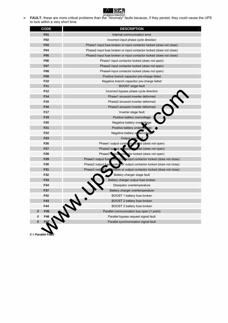
FAULT: these are more critical problems than the "Anomaly" faults because, if they persist, they could cause the UPS to lock within a very short time.
CODE DESCRIPTION
F01 Internal communication error
F02 Incorrect input phase cycle direction
F03 Phase1 input fuse broken or input contactor locked (does not close)
F04 Phase2 input fuse broken or input contactor locked (does not close)
F05 Phase3 input fuse broken or input contactor locked (does not close)
F06 Phase1 input contactor locked (does not open)
F07 Phase2 input contactor locked (does not open)
F08 Phase4 input contactor locked (does not open)
F09 Positive branch capacitor pre-charge failed F10 Negative branch capacitor pre-charge failed F11 BOOST stage fault
F12 Incorrect bypass phase cycle direction
F14 Phase1 sinusoid inverter deformed
F15 Phase2 sinusoid inverter deformed
F16 Phase3 sinusoid inverter deformed
F17 Inverter stage fault
F19 Positive battery overvoltage
F20 Negative battery overvoltage
F21 Positive battery undervoltage
F22 Negative battery undervoltage
F23 Output overload
F26 Phase1 output contactor locked (does not open)
F27 Phase2 output contactor locked (does not open)
F28 Phase3 output contactor locked (does not open)
F29 Phase1 output fuse broken or output contactor locked (does not close)
F30 Phase2 output fuse broken or output contactor locked (does not close)
F31 Phase3 output fuse broken or output contactor locked (does not close)
F32 Battery charger stage fault
F33 Battery charger output fuse broken
F34 Dissipator overtemperature
F37 Battery charger overtemperature
F42 BOOST 1 battery fuse broken
F43 BOOST 2 battery fuse broken
F44 BOOST 3 battery fuse broken
// F45 Parallel communication bus open (1 point)
// F46 Parallel bypass request signal fault
// F47 Parallel synchronization signal fault
// = Parallel Fault www.upsd
irect.
com

LOCK: indicate UPS or a UPS component lock and usually is preceded by an alarm signal. In the event of a fault and consequential inverter lock, the inverter and power to the load via the bypass line will switch off (this procedure is excluded for locks due to serious, persistent overloads and short circuits).
CODE DESCRIPTION
L01 Incorrect auxiliary power supply
L02 Disconnection of one or more internal cables
L03 Phase1 input fuse broken or input contactor locked (does not close)
L04 Phase2 input fuse broken or input contactor locked (does not close)
L05 Phase3 input fuse broken or input contactor locked (does not close)
L06 Positive BOOST stage overvoltage
L07 Negative BOOST stage overvoltage
L08 Positive BOOST stage undervoltage
L09 Negative BOOST stage undervoltage
L10 Static bypass switch fault
L11 L1 bypass output locked
L12 L2 bypass output locked
L13 L3 bypass output locked
L14 Phase1 inverter overvoltage
L15 Phase2 inverter overvoltage
L16 Phase3 inverter overvoltage
L17 Phase1 inverter undervoltage
L18 Phase2 inverter undervoltage
L19 Phase3 inverter undervoltage
L20 Continuous voltage on inverter output or Phase1 sinusoid inverter deformed
L21 Continuous voltage on inverter output or Phase2 sinusoid inverter deformed
L22 Continuous voltage on inverter output or Phase3 sinusoid inverter deformed
L23 Phase1 output overload
L24 Phase2 output overload
L25 Phase3 output overload
L26 Phase1 output short-circuit
L27 Phase2 output short-circuit
L28 Phase3 output short-circuit
L29 Phase1 output fuse broken or output contactor locked (does not close)
// L32 Parallel synchronization error
// L33 Parallel synchronization signal fault
L30 Phase2 output fuse broken or output contactor locked (does not close)
L31 Phase3 output fuse broken or output contactor locked (does not close)
L34 Phase1 dissipator overtemperature
L35 Phase2 dissipator overtemperature
L36 Phase3 dissipator overtemperature
L37 Battery charger overtemperature
L38 Phase1 dissipator temperature sensor fault L39 Phase2 dissipator temperature sensor fault
L40 Phase3 dissipator temperature sensor fault
L41 Battery charger temperature sensor fault
L42 BOOST 1 battery fuse broken
L43 BOOST 2 battery fuse broken
L44 BOOST 3 battery fuse broken
// L45 Parallel bus separation // L46 Parallel communication fault // L47 Parallel board fault // L48 Remote unit lock
// = Parallel Lock
www.upsd
irect.
com

TECHNICAL DATA
UPS Models MST 60 MST 80
INPUT STAGE
Nominal Voltage 380-400-415 V AC Three-phase with neutral (4 wire)
Nominal Frequency 50-60Hz
Maximum input current (1) 96A 125A
Maximum battery current 150A 200A
Input voltage tolerance accepted for no battery intervention (referred to 400V AC)
20% @ 100% load -40% +20% @50% load
Input frequency tolerance accepted for no battery intervention (referred to 50/60Hz)
20% 40-72Hz
Input current Harmonic Distortion THDi 3 % (2)
Input power factor 0.99
Power Walk In mode Programmable from 5 to 125 sec. at steps of 1 sec
OUTPUT STAGE
Nominal Voltage (3) 380/400/415 V AC three-phase with neutral (4 wire)
Nominal Frequency (4) 50/60Hz
Output nominal current 87A 116A
Nominal apparent power in output 60kVA 80kVA
Nominal active power in output 54kW 72kW
Output power factor 0.9
Short-circuit current 1.5 x In for t 500ms
Output voltage precision (referred to output voltage 400V AC) 1%
Static stability (5) 0.5%
Dynamic stability 3% resistive load (6)
Output voltage harmonic distortion with linear load and normalized distortion
1% with linear load 3% with distorted load
Crest factor accepted at nominal load 3:1
Frequency accuracy in free running mode 0.01%
Inverter overload (Vin>345V AC )
Load ≤ 103% → Infinite Load = 110% → 10 min Load = 125% → 1 min Load = 150% → 5 sec
Bypass Overload
Load ≤ 110% → Infinite Load = 125% → 60 minutes Load = 150% → 10 minutes
Load >150% → 2 sec
BATTERY CHARGE STAGE
Nominal voltage 240Vdc
Maximum recharging current (7) 10A (20A optional)
www.upsd
irect.
com

UPS Models MST 60 MST 80
MODE AND EFFICIENCY
Operating mode
True on line double conversion Eco mode
Smart Active mode Stand By Off (Emergency power supply)
Frequency Converter
AC/DC yield in on line mode Up to 99%
OTHER
Noise level ≤ 56dB(A)
Casing degree of protection IP20
Ambient temperature (8) 0 - 40 °C
Colour RAL 7016
(1) Maximum input current in conditions: nominal load (PF=0,9), 380V input voltage and batteries charging with 10A
(2) @ 100% load & THDv ≤ 1%
(3) To maintain output voltage within the specified accuracy range, recalibration may be necessary after a long period of operation
(4) If network frequency is within ± 5% of the selected value, the UPS is synchronized with the network. If frequency is out of the range of
tolerance or in battery operation, the frequency is the one selected +0.01% (5)
Mains/Battery @ load 0% -100% (6)
@ Mains / battery / network @ resistive load 0% / 100% / 0%
(7) Recharging current is automatically regulated on the basis of installed battery capacity
(8) 20 – 25 °C for longer battery life
www.upsd
irect.
com
[email protected] +44 (0)8456 445 002 www.upsdirect.com
UPS Direct Ltd Column House, London Road
Shrewsbury SY2 6NN England