Embed Size (px)
Citation preview
ETSI ES 203 156 V1.1.1 (2013-09)
Environmental Engineering (EE); Thermal Management requirements for outdoor enclosures
ETSI Standard
ETSI
ETSI ES 203 156 V1.1.1 (2013-09) 2
Reference DES/EE-01027
Keywords air flow, cooling capacity, environment,
management, outdoor enclosure, thermal
ETSI
650 Route des Lucioles F-06921 Sophia Antipolis Cedex - FRANCE
Tel.: +33 4 92 94 42 00 Fax: +33 4 93 65 47 16
Siret N° 348 623 562 00017 - NAF 742 C
Association à but non lucratif enregistrée à la Sous-Préfecture de Grasse (06) N° 7803/88
Important notice
Individual copies of the present document can be downloaded from: http://www.etsi.org
The present document may be made available in more than one electronic version or in print. In any case of existing or perceived difference in contents between such versions, the reference version is the Portable Document Format (PDF).
In case of dispute, the reference shall be the printing on ETSI printers of the PDF version kept on a specific network drive within ETSI Secretariat.
Users of the present document should be aware that the document may be subject to revision or change of status. Information on the current status of this and other ETSI documents is available at
http://portal.etsi.org/tb/status/status.asp
If you find errors in the present document, please send your comment to one of the following services: http://portal.etsi.org/chaircor/ETSI_support.asp
Copyright Notification
No part may be reproduced except as authorized by written permission. The copyright and the foregoing restriction extend to reproduction in all media.
© European Telecommunications Standards Institute 2013.
All rights reserved.
DECTTM, PLUGTESTSTM, UMTSTM and the ETSI logo are Trade Marks of ETSI registered for the benefit of its Members. 3GPPTM and LTE™ are Trade Marks of ETSI registered for the benefit of its Members and
of the 3GPP Organizational Partners. GSM® and the GSM logo are Trade Marks registered and owned by the GSM Association.
ETSI
ETSI ES 203 156 V1.1.1 (2013-09) 3
Contents
Intellectual Property Rights ................................................................................................................................ 5
Foreword ............................................................................................................................................................. 5
Introduction ........................................................................................................................................................ 5
1 Scope ........................................................................................................................................................ 6
2 References ................................................................................................................................................ 6
2.1 Normative references ......................................................................................................................................... 6
2.2 Informative references ........................................................................................................................................ 6
3 Definitions, symbols and abbreviations ................................................................................................... 7
3.1 Definitions .......................................................................................................................................................... 7
3.2 Symbols .............................................................................................................................................................. 8
3.3 Abbreviations ..................................................................................................................................................... 8
4 General requirements ............................................................................................................................... 8
4.1 Thermal performance of outdoor enclosures ...................................................................................................... 8
4.2 Environmental class requirements for equipment installed in outdoor enclosures ............................................. 8
4.2.1 Free cooling cabinet ...................................................................................................................................... 8
4.2.2 Heat exchanger cabinet ................................................................................................................................. 8
4.2.3 Air conditioning cabinet ............................................................................................................................... 9
5 Thermal management ............................................................................................................................... 9
5.1 Standardized definition of cooling capacity ....................................................................................................... 9
5.2 Maximum acceptable delta T ........................................................................................................................... 10
5.3 The preferable rule for air flow ........................................................................................................................ 10
5.3.1 Air flow paths of outdoor enclosures .......................................................................................................... 10
5.3.2 Preferable rule for air flow path match ....................................................................................................... 11
5.3.2.1 Door-mounted TCU .............................................................................................................................. 11
5.3.2.2 Roof -mounted TCU ............................................................................................................................. 12
5.3.2.3 Side-mounted TCU ............................................................................................................................... 13
Annex A (normative): Thermal characterization data of outdoor enclosures to be provided by the manufacturer ...................................................................................... 14
A.1 General identification ............................................................................................................................. 14
A.1.1 Identification .................................................................................................................................................... 14
A.1.2 Physical geometry ............................................................................................................................................ 14
A.2 Additional data for outdoor enclosures .................................................................................................. 14
A.2.1 Mechanical characteristics of outdoor enclosures ............................................................................................ 15
A.2.2 Fan/Fan tray...................................................................................................................................................... 15
A.2.3 Air filter of outdoor enclosures ........................................................................................................................ 15
A.2.4 Airflow paths .................................................................................................................................................... 16
A.2.5 Cooling capacity ............................................................................................................................................... 16
Annex B (informative): Ambient temperature measurement point .................................................. 17
B.1 measurement point requirement ............................................................................................................. 17
Annex C (informative): Solar radiation................................................................................................ 18
Annex D (informative): Requirements for safety and EMC ............................................................... 19
D.1 Requirements for safety.......................................................................................................................... 19
D.2 Requirements for EMC .......................................................................................................................... 19
D.3 Acoustic Noise Level requirement ......................................................................................................... 19
ETSI
ETSI ES 203 156 V1.1.1 (2013-09) 4
Annex E (informative): Cabinet performance parameters ................................................................ 20
Annex F (informative): Bibliography ................................................................................................... 21
History .............................................................................................................................................................. 22
ETSI
ETSI ES 203 156 V1.1.1 (2013-09) 5
Intellectual Property Rights IPRs essential or potentially essential to the present document may have been declared to ETSI. The information pertaining to these essential IPRs, if any, is publicly available for ETSI members and non-members, and can be found in ETSI SR 000 314: "Intellectual Property Rights (IPRs); Essential, or potentially Essential, IPRs notified to ETSI in respect of ETSI standards", which is available from the ETSI Secretariat. Latest updates are available on the ETSI Web server (http://ipr.etsi.org).
Pursuant to the ETSI IPR Policy, no investigation, including IPR searches, has been carried out by ETSI. No guarantee can be given as to the existence of other IPRs not referenced in ETSI SR 000 314 (or the updates on the ETSI Web server) which are, or may be, or may become, essential to the present document.
Foreword This ETSI Standard (ES) has been produced by ETSI Technical Committee Environmental Engineering (EE).
Introduction Outdoor enclosure suppliers are trying to overcome their thermal issues in different solutions being developed. When different equipments and outdoor enclosures from various suppliers are integrated, they can have a detrimental effect on each other. The present document specifies the thermal management requirements for outdoor enclosures (defined in EN 301 169-1 [i.4] and EN 301 169-2 [i.5]) to prevent outdoor enclosures having a detrimental thermal influence on equipments inside.
ETSI
ETSI ES 203 156 V1.1.1 (2013-09) 6
1 Scope The present document describes the thermal management requirements for outdoor enclosures defined in EN 301 169-1 [i.4] and EN 301 169-2 [i.5]. These thermal management requirements to be defined include:
• a standardized definition of cooling capacity for outdoor enclosures;
• a maximum acceptable delta T between ambient temperature and inside temperature;
• the preferable rule for air flow inside outdoor enclosures;
• the environment class for equipment to be installed in outdoor enclosures.
Not all these requirement are applicable to outdoor enclosures defined in EN 301 169-1 [i.4] and EN 301 169-2 [i.5]; maximum acceptable delta T for equipment in line with EN 301 169-1 [i.4] should be considered as a guide to developer.
The purpose of the present document is to make it more easy to define the responsibility of equipment manufacturers, cabinet manufacturers and integrators.
The present document applies for those empty outdoor enclosures supplied for housing telecommunication equipment of wireline and wireless access network and other information technology equipment.
EMC, safety and acoustic noise requirements are not parts of the present document. Guidance on these aspects are contained in annex D.
2 References References are either specific (identified by date of publication and/or edition number or version number) or non-specific. For specific references, only the cited version applies. For non-specific references, the latest version of the reference document (including any amendments) applies.
Referenced documents which are not found to be publicly available in the expected location might be found at http://docbox.etsi.org/Reference.
NOTE: While any hyperlinks included in this clause were valid at the time of publication, ETSI cannot guarantee their long term validity.
2.1 Normative references The following referenced documents are necessary for the application of the present document.
[1] ETSI EN 300 019-1-4: "Environmental Engineering (EE); Environmental conditions and environmental tests for telecommunications equipment; Part 1-4: Classification of environmental conditions; Stationary use at non-weatherprotected locations".
[2] ETSI EN 300 019-1-3: "Environmental Engineering (EE); Environmental conditions and environmental tests for telecommunications equipment; Part 1-3: Classification of environmental conditions; Stationary use at weatherprotected locations".
2.2 Informative references The following referenced documents are not necessary for the application of the present document but they assist the user with regard to a particular subject area.
[i.1] ETSI EN 300 386: "Electromagnetic compatibility and Radio spectrum Matters (ERM);Telecommunication network equipment; ElectroMagnetic Compatibility (EMC) requirements".
ETSI
ETSI ES 203 156 V1.1.1 (2013-09) 7
[i.2] ETSI EN 301 489-1: "Electromagnetic compatibility and Radio spectrum Matters (ERM); ElectroMagnetic Compatibility (EMC) standard for radio equipment and services; Part 1: Common technical requirements".
[i.3] IEC 61969-3: "Mechanical structures for electronic equipment - Outdoor enclosures - Part 3: Sectional specification - Climatic, mechanical tests and safety aspects for cabinets and cases".
[i.4] ETSI EN 301 169-1: "Equipment practice; Engineering requirements for outdoor enclosures; Part 1: Equipped enclosures".
[i.5] ETSI EN 301 169-2: "Equipment practice; Engineering requirements for outdoor enclosures; Part 2: Unequipped enclosures".
[i.6] ETSI EN 300 119-5: "Environmental Engineering (EE); European telecommunication standard for equipment practice; Part 5: Thermal management".
[i.7] CENELEC EN 60950-1: "Information technology equipment - Safety - Part 1: General requirements".
[i.8] CENELEC EN 60950-22: "Information technology equipment - Safety - Part 22: Equipment installed outdoors".
[i.9] ETSI EN 300 753: "Environmental Engineering (EE); Acoustic noise emitted by telecommunications equipment".
[i.10] ETSI EN 300 019-2-4: "Environmental Engineering (EE); Environmental conditions and environmental tests for telecommunications equipment; Part 2-4: Specification of environmental tests; Stationary use at non-weatherprotected locations".
[i.11] ETSI TR 101 576: "Environmental Engineering (EE); Recommendation for the applicability of environmental classes in outdoor cabinet environment".
3 Definitions, symbols and abbreviations
3.1 Definitions For the purposes of the present document, the following terms and definitions apply:
air conditioning: cooling technology where an operating refrigerator system is used for cooling the internal air of the enclosure
ambient: spatial maximal temperature of the air entering the rack/cabinet
cabinet: free-standing and self-supporting enclosure for housing electrical and/or electronics equipment, usually fitted with doors and/or side panels which may or may not be removable
free cooling: cooling technology in which the external air is directly used for the inside heat removal; also called direct free cooling
heat exchanger: cooling technology in which the inside heat removal is provided (actively with fans or passively without fans) without directly use of outside air but using an exchange between two fluids (e.g. air to air or water to air)
integrator: end user/operator of telecommunication or IT equipment or their agent
NOTE: For example an equipment manufacturer could be an operator's agent.
micro-climate: conditions found within the rack/cabinet creating a local ambient for the subrack
outdoor enclosures: enclosure exposed for the outdoor environment, for stationary use at non-weatherprotected locations, for the protection of electronic equipment installed inside against outdoor environmental conditions (IEC 61969-3 [i.3])
ETSI
ETSI ES 203 156 V1.1.1 (2013-09) 8
outdoor location: location for equipment where protection from the weather and other outdoor influences provided by a building or other structure is limited or non-existent
3.2 Symbols For the purposes of the present document, the following symbols apply:
K cooling capacity of outdoor enclosure [W/°C] Q heat dissipation from equipment inside cabinet [W] Tambient surrounding ambient temperature [°C] in which the outdoor enclosure is positioned Tinlet temperature of air at the equipment inlet inside the cabinet [°C] △T temperature difference between Tinlet and Tambient [°C]
3.3 Abbreviations For the purposes of the present document, the following abbreviations apply:
COP Coefficient Of Performance ICT Information and Communication Technology TCU Temperature Control Unit (for example, fresh air cooling , heat- exchanger, air-conditioner)
4 General requirements
4.1 Thermal performance of outdoor enclosures The supplier of outdoor enclosures shall design the cabinet so that the product fulfils the outdoor environment as detailed in EN 300 019-1-4 [1], class 4.1. And under this environment class, the cabinet can ensure the equipments whose environment class is defined in clause 4.2 of the present document to work in appropriate micro-climate.
To enable the operators/integrators to predict the thermal performance of outdoor enclosures and to decide the equipment configuration inside, The supplier of outdoor enclosures should provide the relevant thermal characteristics detailed in annex A of the present document.
4.2 Environmental class requirements for equipment installed in outdoor enclosures
Possible use of environmental class for equipment installed in outdoor enclosures is discussed in TR 101 576 [i.11].
The outdoor enclosure provides a weather protected environment for the inside equipment. For effective cooling, the equipment inlet air temperature, using some cooling technologies, is higher than the outdoor air temperature.
In the following is considered that the outdoor enclosure is required to meet EN 300 019-1-4 [1], class 4.1 with temperature range from -33 °C to +40 °C; in this case the climatic conditions for the equipment inside the outdoor cabinet shall be those defined in the following clauses.
4.2.1 Free cooling cabinet
• Climatic conditions in line with Class 3.3 (see EN 300 019-1-3 [2]).
4.2.2 Heat exchanger cabinet
• Climatic conditions in line with Class 3.3 (see EN 300 019-1-3 [2]).
ETSI
ETSI ES 203 156 V1.1.1 (2013-09) 9
4.2.3 Air conditioning cabinet
• Climatic conditions in line with Class 3.2 (see EN 300 019-1-3 [2]).
On request, the supplier of the equipment shall be able to provide relevant information about the equipment. This information should be described in a way that is specified in EN 300 119-5 [i.6], annex A.
The outdoor enclosure may need to provide an additional heating solution if the inside equipment cannot start up from cold in a low ambient temperature.
Air conditioning requires the use of refrigerants; caution when selecting a refrigerant that it shall not be harmful to the environment.
Air conditioning should be limited to critical case e.g. high power (heat) dissipation in related not big volume cabinet.
5 Thermal management
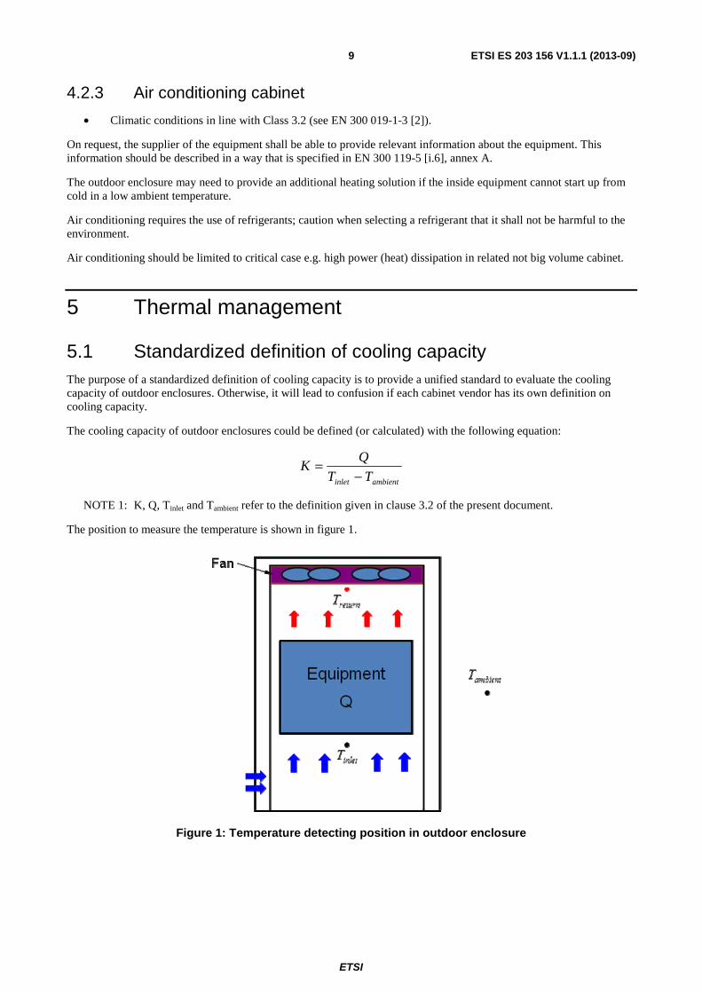
5.1 Standardized definition of cooling capacity The purpose of a standardized definition of cooling capacity is to provide a unified standard to evaluate the cooling capacity of outdoor enclosures. Otherwise, it will lead to confusion if each cabinet vendor has its own definition on cooling capacity.
The cooling capacity of outdoor enclosures could be defined (or calculated) with the following equation:
ambientinlet TT
QK
−=
NOTE 1: K, Q, Tinlet and Tambient refer to the definition given in clause 3.2 of the present document.
The position to measure the temperature is shown in figure 1.
Figure 1: Temperature detecting position in outdoor enclosure
ETSI
ETSI ES 203 156 V1.1.1 (2013-09) 10
NOTE 2: Example of calculation using formula is reported here for clarification.
The cooling capacity of outdoor enclosure K may vary with the ambient temperature Tambient because of the auto-adjusted speed of fans. For example, one outdoor enclosure housing a 1 000 W heat load equipment, when the Tambient is 45 °C, the fans will work under 100 % speed to keep the △T in 10 °C, the K of this outdoor enclosure will be 100 W/ °C, however when the Tambient is 25 °C, the fans may work under 50 % speed to keep the △T in 15 °C, the K of this outdoor enclosure will be 66,7 W/ °C.
5.2 Maximum acceptable delta T To create an appropriate micro-climate for equipment installed in outdoor cabinets, the cabinet should be designed to ensure the equipment installed in cabinet can work at its temperature limit. Moreover, the cabinet should be designed in a way to make the △T (the delta T between Tinlet and Tambient inside of the equipment, see figure 1) as small as possible (below +10 °C is recommended), while the equipment is operating at maximum temperature according to the environment class for equipment installed in outdoor cabinet.
NOTE 1: The integrators should be responsible for a good match between the air flow path of outdoor cabinet and the air flow path of equipment installed in the outdoor cabinet.
NOTE 2: The △T value depends on type of cooling mode applied (in air conditioning cabinet this value could be negative).
5.3 The preferable rule for air flow The air flow path of equipment (or subrack) has been defined in EN 300 119-5 [i.6], clause 5.1: The preferred air flow route into a subrack is in at the left, front or bottom and out at the right, back or top.
It is also important to define a preferable air flow rule for outdoor enclosures, thus helping operators (or integrators) to match the equipment's (or subrack's) air flow path well with the outdoor enclosure's cooling system.
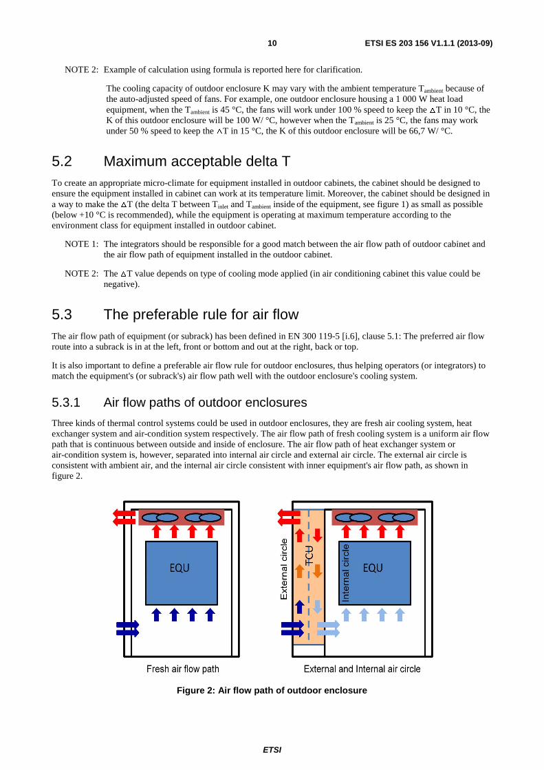
5.3.1 Air flow paths of outdoor enclosures
Three kinds of thermal control systems could be used in outdoor enclosures, they are fresh air cooling system, heat exchanger system and air-condition system respectively. The air flow path of fresh cooling system is a uniform air flow path that is continuous between outside and inside of enclosure. The air flow path of heat exchanger system or air-condition system is, however, separated into internal air circle and external air circle. The external air circle is consistent with ambient air, and the internal air circle consistent with inner equipment's air flow path, as shown in figure 2.
Figure 2: Air flow path of outdoor enclosure
ETSI
ETSI ES 203 156 V1.1.1 (2013-09) 11
5.3.2 Preferable rule for air flow path match
The design of the internal air flow path of the outdoor enclosure is related to the type and location of the Temperature Control Unit (TCU), and there shall be a good match between the air flow TCU and the inner equipment. The air flow path of the inner equipment shall comply to EN 300 119-5 [i.6], clause 5.1: The preferred air flow route into a subrack is in at the left, front or bottom and out at the right, back or top.
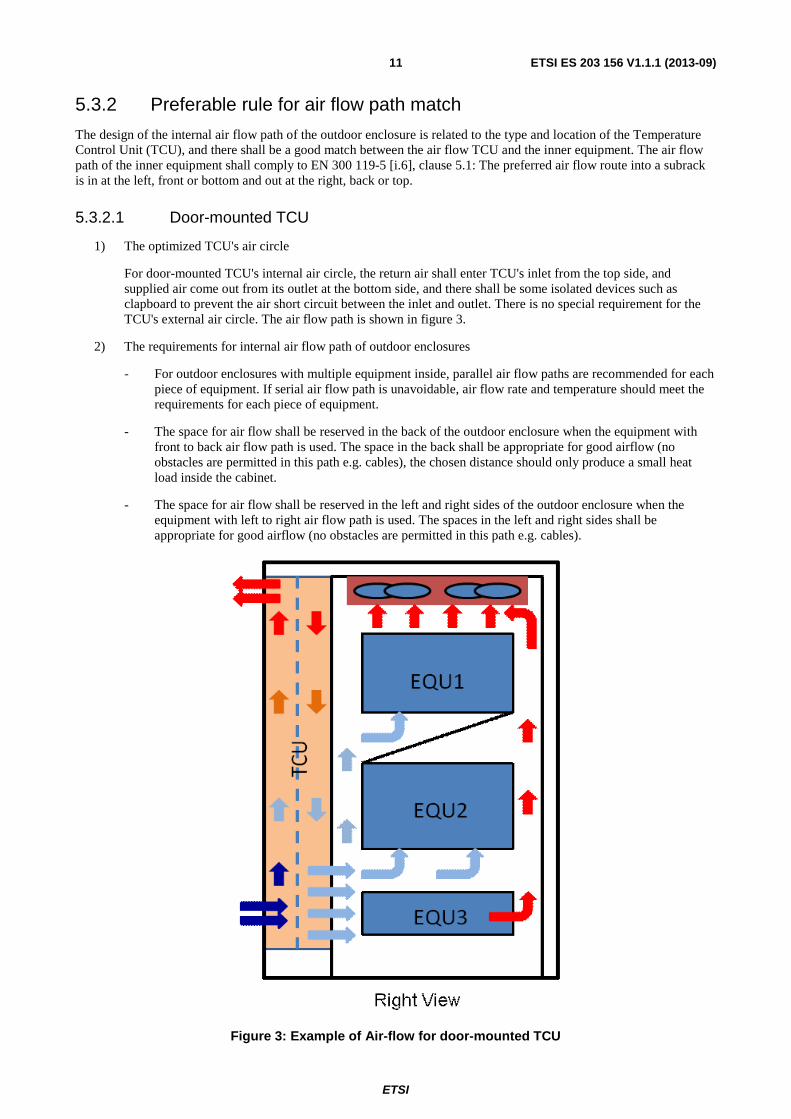
5.3.2.1 Door-mounted TCU
1) The optimized TCU's air circle
For door-mounted TCU's internal air circle, the return air shall enter TCU's inlet from the top side, and supplied air come out from its outlet at the bottom side, and there shall be some isolated devices such as clapboard to prevent the air short circuit between the inlet and outlet. There is no special requirement for the TCU's external air circle. The air flow path is shown in figure 3.
2) The requirements for internal air flow path of outdoor enclosures
- For outdoor enclosures with multiple equipment inside, parallel air flow paths are recommended for each piece of equipment. If serial air flow path is unavoidable, air flow rate and temperature should meet the requirements for each piece of equipment.
- The space for air flow shall be reserved in the back of the outdoor enclosure when the equipment with front to back air flow path is used. The space in the back shall be appropriate for good airflow (no obstacles are permitted in this path e.g. cables), the chosen distance should only produce a small heat load inside the cabinet.
- The space for air flow shall be reserved in the left and right sides of the outdoor enclosure when the equipment with left to right air flow path is used. The spaces in the left and right sides shall be appropriate for good airflow (no obstacles are permitted in this path e.g. cables).
Figure 3: Example of Air-flow for door-mounted TCU
ETSI
ETSI ES 203 156 V1.1.1 (2013-09) 12
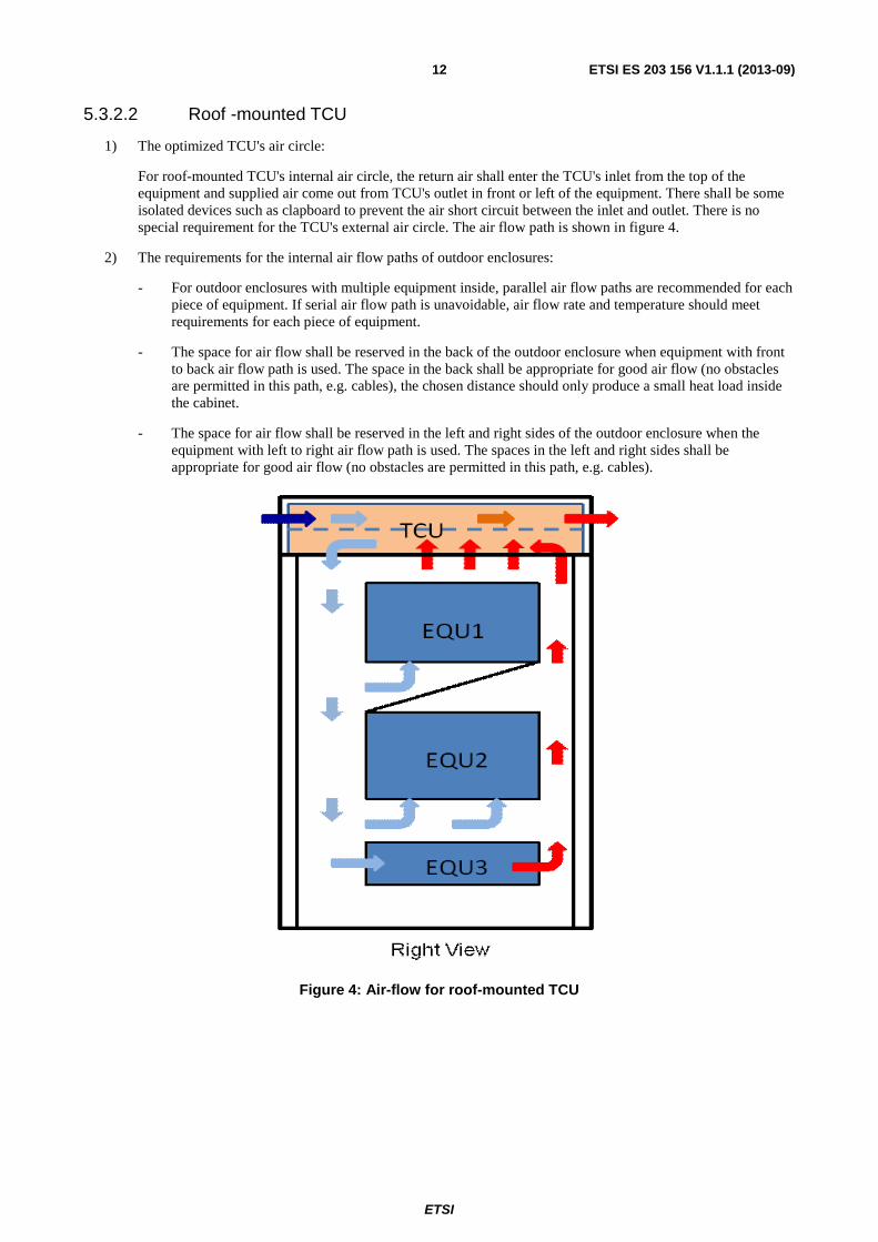
5.3.2.2 Roof -mounted TCU
1) The optimized TCU's air circle:
For roof-mounted TCU's internal air circle, the return air shall enter the TCU's inlet from the top of the equipment and supplied air come out from TCU's outlet in front or left of the equipment. There shall be some isolated devices such as clapboard to prevent the air short circuit between the inlet and outlet. There is no special requirement for the TCU's external air circle. The air flow path is shown in figure 4.
2) The requirements for the internal air flow paths of outdoor enclosures:
- For outdoor enclosures with multiple equipment inside, parallel air flow paths are recommended for each piece of equipment. If serial air flow path is unavoidable, air flow rate and temperature should meet requirements for each piece of equipment.
- The space for air flow shall be reserved in the back of the outdoor enclosure when equipment with front to back air flow path is used. The space in the back shall be appropriate for good air flow (no obstacles are permitted in this path, e.g. cables), the chosen distance should only produce a small heat load inside the cabinet.
- The space for air flow shall be reserved in the left and right sides of the outdoor enclosure when the equipment with left to right air flow path is used. The spaces in the left and right sides shall be appropriate for good air flow (no obstacles are permitted in this path, e.g. cables).
Figure 4: Air-flow for roof-mounted TCU
ETSI
ETSI ES 203 156 V1.1.1 (2013-09) 13
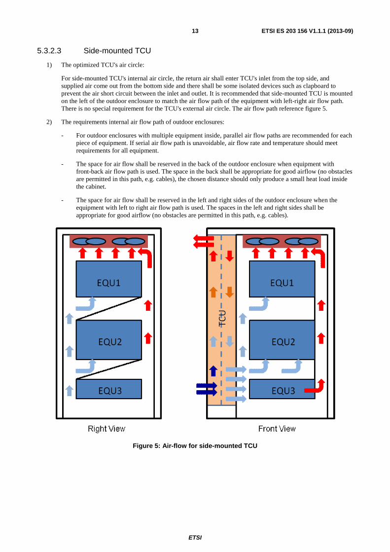
5.3.2.3 Side-mounted TCU
1) The optimized TCU's air circle:
For side-mounted TCU's internal air circle, the return air shall enter TCU's inlet from the top side, and supplied air come out from the bottom side and there shall be some isolated devices such as clapboard to prevent the air short circuit between the inlet and outlet. It is recommended that side-mounted TCU is mounted on the left of the outdoor enclosure to match the air flow path of the equipment with left-right air flow path. There is no special requirement for the TCU's external air circle. The air flow path reference figure 5.
2) The requirements internal air flow path of outdoor enclosures:
- For outdoor enclosures with multiple equipment inside, parallel air flow paths are recommended for each piece of equipment. If serial air flow path is unavoidable, air flow rate and temperature should meet requirements for all equipment.
- The space for air flow shall be reserved in the back of the outdoor enclosure when equipment with front-back air flow path is used. The space in the back shall be appropriate for good airflow (no obstacles are permitted in this path, e.g. cables), the chosen distance should only produce a small heat load inside the cabinet.
- The space for air flow shall be reserved in the left and right sides of the outdoor enclosure when the equipment with left to right air flow path is used. The spaces in the left and right sides shall be appropriate for good airflow (no obstacles are permitted in this path, e.g. cables).
Figure 5: Air-flow for side-mounted TCU
ETSI
ETSI ES 203 156 V1.1.1 (2013-09) 14
Annex A (normative): Thermal characterization data of outdoor enclosures to be provided by the manufacturer In many applications operators (or integrators) purchase equipment and outdoor cabinets from different suppliers, and it has become increasingly important that operators/integrators have information available that enables them to predict the performance of the integrated products. In fact, the thermal performance of an outdoor cabinet is now becoming as critical as the thermal performance of the equipment. The data required by annex A should enable the operators or integrator to review and revise the equipment configuration inside outdoor cabinets.
Any thermal modelling to be undertaken using this data will require geometric information as well as airflow and thermal data. Therefore the data should include geometric information of outdoor enclosures so that this represents a complete list.
The recommended environmental test conditions should be within the range as specified in EN 300 019-1-4 [1].
The actual environmental test conditions used for collection of data shall be provided with the characterization data.
A.1 General identification All outdoor enclosures characterized for thermal management purposes shall have the following identification and physical geometry characteristics specified.
A.1.1 Identification • Manufacturer.
• Model.
A.1.2 Physical geometry The size and geometry of the outdoor enclosure.
• Size.
- Height;
- Width;
- Depth.
In addition to the general identification and physical size, described in this clause, the outdoor enclosures should have the following information defined such that its effect on airflow and heat transfer can be determined.
A.2 Additional data for outdoor enclosures This clause gives the additional data that the supplier shall also provide for outdoor enclosures.
ETSI
ETSI ES 203 156 V1.1.1 (2013-09) 15
A.2.1 Mechanical characteristics of outdoor enclosures To be able to understand the thermal performance of integrated products (for example an empty outdoor cabinet integrated with different pieces of equipment), it is important to know the configuration of the empty cabinet. In addition to the information required in clause A.1 the supplier shall also define:
• which faces have openings and for each opening:
- the size, position and porosity of the inlet and exhaust grids/vents;
- a description of the grid/vent type shall also be given from the following list:
� open;
� perforated;
� slotted;
� grille;
� mesh.
• the shape and size of the mounting flanges for equipment that may obstruct the airflow;
• the location and size of solid parts of the frame that may obstruct the airflow (for example, shelves, baffles, etc.);
• where the outdoor enclosure is supplied with fans/fan trays then the supplier shall also provide details as specified in clause A.2.2;
• where the outdoor enclosure is supplied with air filters then the supplier shall also provide details as specified in clause A.2.3.
A.2.2 Fan/Fan tray Fans or Fan trays often make an important contribution to air movement in an outdoor enclosure. These are separate items of equipment not the fans that are an integral part of other equipment, that are added to enhance airflow. They can be located at various positions in the outdoor enclosure. The following data shall be supplied (normally by a specialist fan manufacturer):
• flow direction;
• number of fans and their arrangement - e.g. 3 wide by 2 deep;
• for each fan (or group of fans operating as one):
- the fan characteristic (airflow rate, ……) with temperature dependence;
- power dissipation.
A.2.3 Air filter of outdoor enclosures Air filters can restrict the airflow and hence reduce the cooling. Filters of outdoor enclosures are separate from those of the equipment (filters that are an integral part of other equipment) and can be located at various positions in the outdoor enclosure. The following data shall be supplied (normally by a specialist filter manufacturer):
• pressure drop;
• reference velocity for which pressure drop is quoted.
The values shall be repeated as point pairs for several reference velocities for a complete representation throughout the normal range of application.
ETSI
ETSI ES 203 156 V1.1.1 (2013-09) 16
A.2.4 Airflow paths To achieve a good thermal performance, the equipment's airflow paths should be a good match with the cabinet's airflow paths. So it is important for operators/integrators to know the airflow paths of outdoor enclosures. The supplier should provide the airflow path information of outdoor enclosures that they manufacture. The following information shall be supplied:
• airflow information.
A.2.5 Cooling capacity To enable the operators/integrators to predict if the cooling system will meet with the heat dissipation requirement of equipment that will be installed in the outdoor enclosure, it is important for operators/integrators to know the cooling capacity of the outdoor enclosure. The supplier should provide the outdoor enclosure's cooling capacity K defined in clause 5.1 of the present document.
NOTE: The outdoor enclosure's cooling capacity K may depend on the ambient air temperature (Tambient). So a series of K at different Tambient may be provided.
ETSI
ETSI ES 203 156 V1.1.1 (2013-09) 17
Annex B (informative): Ambient temperature measurement point
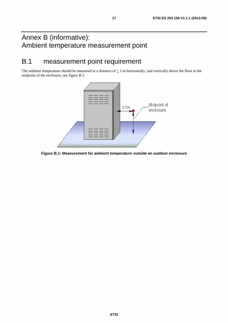
B.1 measurement point requirement The ambient temperature should be measured at a distance of ≥ 1 m horizontally, and vertically above the floor at the midpoint of the enclosure, see figure B.1.
Figure B.1: Measurement for ambient temperature outside an outdoor enclosure
ETSI
ETSI ES 203 156 V1.1.1 (2013-09) 18
Annex C (informative): Solar radiation Solar radiation should be considered during the development of the cabinet. A solution such as a solar shield is an available solution. EN 300 019-2-4 [i.10] simulates the effect of solar radiation increasing the high temperature of testing of 15 °C.
ETSI
ETSI ES 203 156 V1.1.1 (2013-09) 19
Annex D (informative): Requirements for safety and EMC
D.1 Requirements for safety Requirements for safety are defined in specified safety standards. Applicable safety standards for information and communication technology equipment (ICT) are EN 60950-1 [i.7] and EN 60950-22 [i.8].
The maximum temperature of exhaust air from cabinet or cooling system should be lower than 75 ℃.
Maximum temperature of touchable parts (e.g. the external wall) should be in line with table 4c IEC 60950-1.
D.2 Requirements for EMC Requirements for EMC are outside the scope of the present document.
Examples of applicable EMC standards are EN 300 386 [i.1] for not radio equipment and EN 301 489-1 [i.2] for radio equipment.
D.3 Acoustic Noise Level requirement Noise level generated by outdoor enclosures is strictly related to the cooling solution adopted.
For the declared A-weighted sound power level of outdoor enclosure, the local legislation applies. In case of no local legislation, the limits recommended in EN 300 753 [i.9], referring to annex B (informative) may apply (see table B.2: Recommended limits for stationary equipment used in non-weather protected locations).
NOTE: Acoustic noise emission from outdoor enclosures should be measured under the heat load declared by suppliers.
ETSI
ETSI ES 203 156 V1.1.1 (2013-09) 20
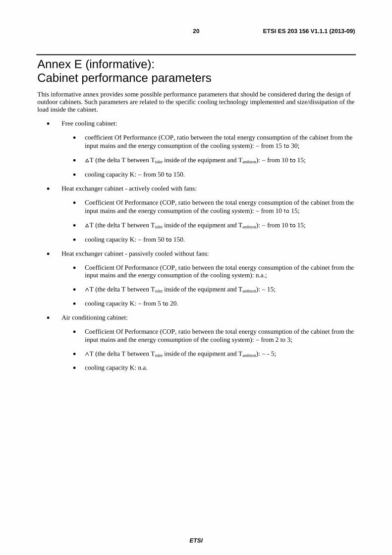
Annex E (informative): Cabinet performance parameters This informative annex provides some possible performance parameters that should be considered during the design of outdoor cabinets. Such parameters are related to the specific cooling technology implemented and size/dissipation of the load inside the cabinet.
• Free cooling cabinet:
• coefficient Of Performance (COP, ratio between the total energy consumption of the cabinet from the input mains and the energy consumption of the cooling system): ∼ from 15 to 30;
• △T (the delta T between Tinlet inside of the equipment and Tambient): ∼ from 10 to 15;
• cooling capacity K: ∼ from 50 to 150.
• Heat exchanger cabinet - actively cooled with fans:
• Coefficient Of Performance (COP, ratio between the total energy consumption of the cabinet from the input mains and the energy consumption of the cooling system): ∼ from 10 to 15;
• △T (the delta T between Tinlet inside of the equipment and Tambient): ∼ from 10 to 15;
• cooling capacity K: ∼ from 50 to 150.
• Heat exchanger cabinet - passively cooled without fans:
• Coefficient Of Performance (COP, ratio between the total energy consumption of the cabinet from the input mains and the energy consumption of the cooling system): n.a.;
• △T (the delta T between Tinlet inside of the equipment and Tambient): ∼ 15;
• cooling capacity K: ∼ from 5 to 20.
• Air conditioning cabinet:
• Coefficient Of Performance (COP, ratio between the total energy consumption of the cabinet from the input mains and the energy consumption of the cooling system): ∼ from 2 to 3;
• △T (the delta T between Tinlet inside of the equipment and Tambient): ∼ - 5;
• cooling capacity K: n.a.
ETSI
ETSI ES 203 156 V1.1.1 (2013-09) 21
Annex F (informative): Bibliography
• ATIS-0600010.01.2008 [pre-pub]: "Temperature, Humidity, And Altitude Requirements For Network Telecommunications Equipment Utilized In Outside Plant Environments".
• IEC 61587 series: "Mechanical structures for electronic equipment".
• IEC 60721: "Classification of environment conditions".
ETSI
ETSI ES 203 156 V1.1.1 (2013-09) 22
History
Document history
V1.0.0 July 2013 Membership Approval Procedure MV 20130831: 2013-07-02 to 2013-09-02
V1.1.1 September 2013 Publication