Embed Size (px)
Citation preview
Brajesh Choudhary, Fermilab For LCWS 2006, IISc, Bangalore, India, 9th–13th March
FERMILAB TEST BEAM & THE INTERNATIONAL & THE INTERNATIONAL
LINEAR COLLIDERLINEAR COLLIDER
ILC R&D Meeting, Fermilab, 3 March 2006 Brajesh Choudhary, FNAL 2
ACKNOWLEDGEMENTS
Charles N. Brown
Richard N. Coleman
Carol J. Johnstone
Craig D. Moore
Erik Ramberg
THANKS!
ILC R&D Meeting, Fermilab, 3 March 2006 Brajesh Choudhary, FNAL 3
PLAN OF THE TALK
1. Introduction to Fermilab Accelerator Complex
2. Introduction to Fermilab Fixed Target Beamlines
3. Fermilab Test Beam Facility
4. Present Test Beam Capabilities
5. Approved and Planned Experiments – A Brief Overview
6. What We Intend to do for “YOU” – YES “You the Users”
Gain from Reducing Material in the MTest Beamline
Further Gain from Reduced Length of the MTest Beamline
Meson Center as a possible Test Beam Option
7. Test beams for LHC, NOνA, MINERνA & the ILC
8. Summary & Conclusion
ILC R&D Meeting, Fermilab, 3 March 2006 Brajesh Choudhary, FNAL 4
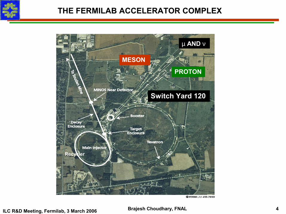
THE FERMILAB ACCELERATOR COMPLEX
Switch Yard 120
MESON
µ AND ν
PROTON
Recycler
ILC R&D Meeting, Fermilab, 3 March 2006 Brajesh Choudhary, FNAL 5
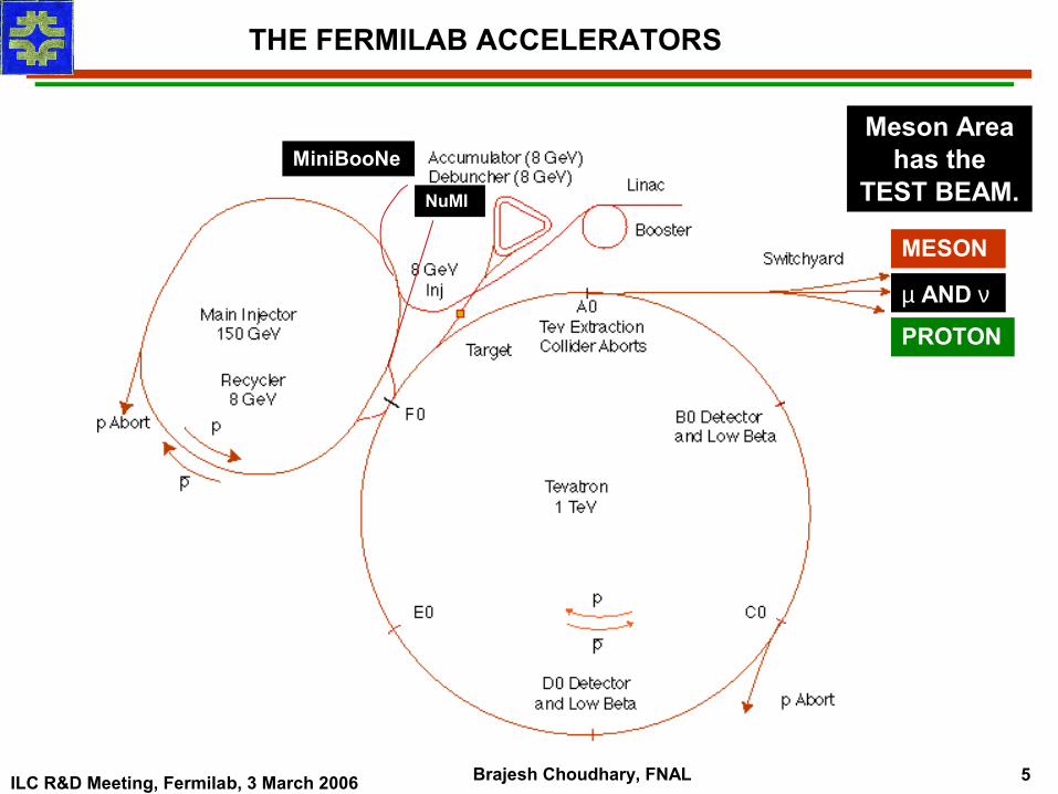
THE FERMILAB ACCELERATORS
MiniBooNe
NuMI
MESON
µ AND ν
PROTON
Meson Area has the
TEST BEAM.
ILC R&D Meeting, Fermilab, 3 March 2006 Brajesh Choudhary, FNAL 6
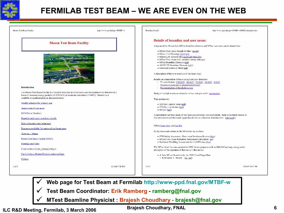
FERMILAB TEST BEAM – WE ARE EVEN ON THE WEB
Web page for Test Beam at Fermilab http://www-ppd.fnal.gov/MTBF-w
Test Beam Coordinator: Erik Ramberg - [email protected]
MTest Beamline Physicist : Brajesh Choudhary - [email protected]
ILC R&D Meeting, Fermilab, 3 March 2006 Brajesh Choudhary, FNAL 7
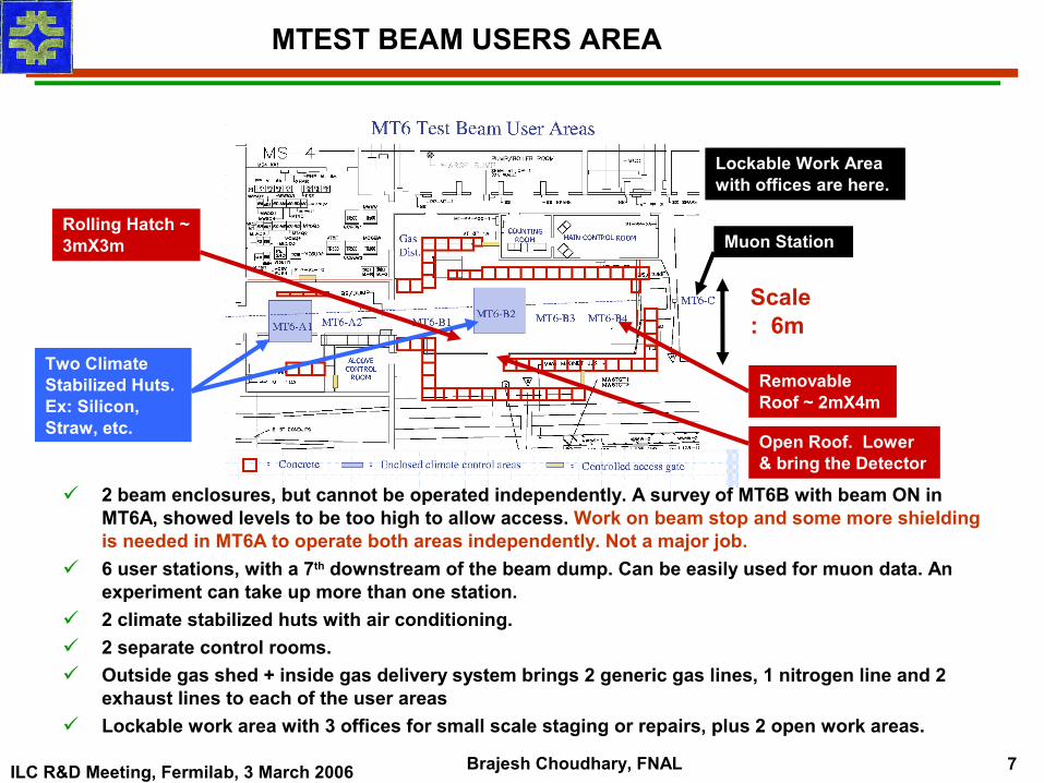
2 beam enclosures, but cannot be operated independently. A survey of MT6B with beam ON in MT6A, showed levels to be too high to allow access. Work on beam stop and some more shielding is needed in MT6A to operate both areas independently. Not a major job.
6 user stations, with a 7th downstream of the beam dump. Can be easily used for muon data. An experiment can take up more than one station.
2 climate stabilized huts with air conditioning. 2 separate control rooms. Outside gas shed + inside gas delivery system brings 2 generic gas lines, 1 nitrogen line and 2
exhaust lines to each of the user areas Lockable work area with 3 offices for small scale staging or repairs, plus 2 open work areas.
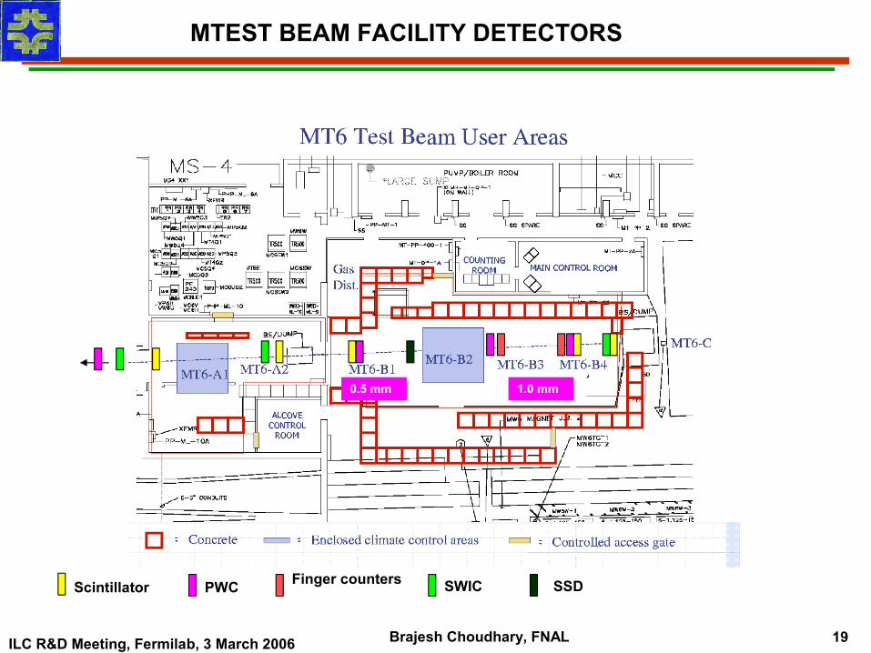
Scale: 6m
MTEST BEAM USERS AREA
Two Climate Stabilized Huts. Ex: Silicon, Straw, etc.
Muon Station
Lockable Work Area with offices are here.
Removable Roof ~ 2mX4m
Rolling Hatch ~ 3mX3m
Open Roof. Lower & bring the Detector
ILC R&D Meeting, Fermilab, 3 March 2006 Brajesh Choudhary, FNAL 8
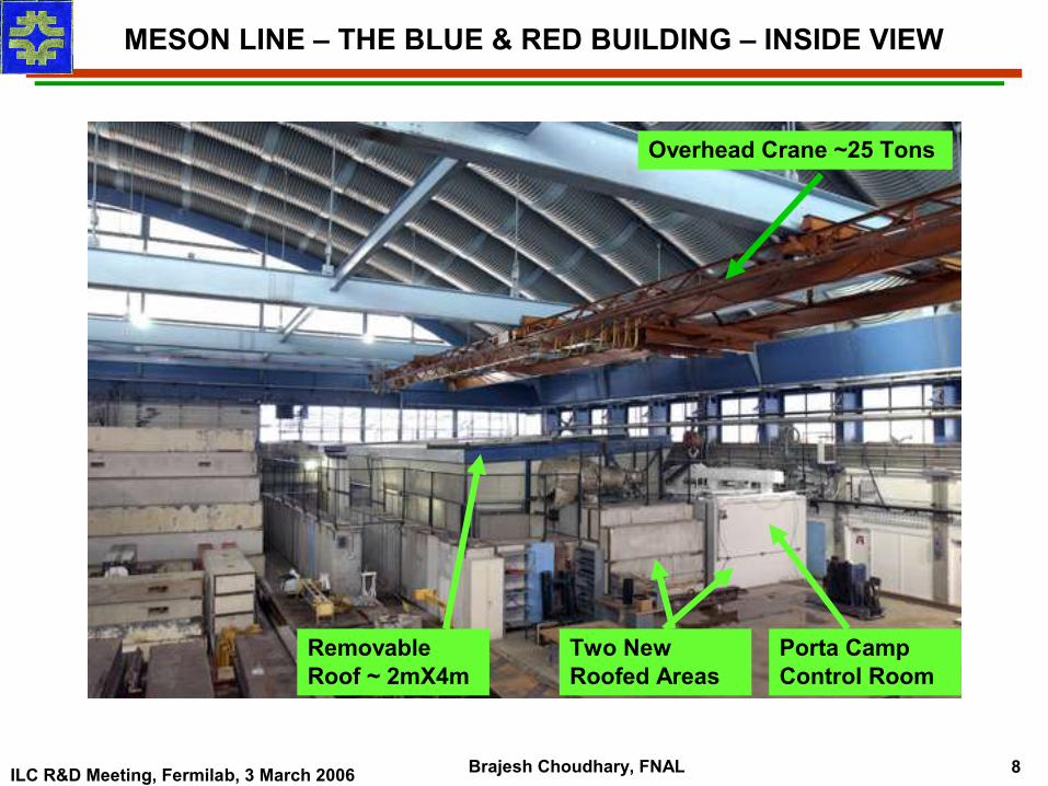
MESON LINE – THE BLUE & RED BUILDING – INSIDE VIEW
Removable Roof ~ 2mX4m
Porta Camp Control Room
Two New Roofed Areas
Overhead Crane ~25 Tons
ILC R&D Meeting, Fermilab, 3 March 2006 Brajesh Choudhary, FNAL 9
TIME STRUCTURE OF THE TEST BEAM
1. The test beam originates from varying number of Booster batches (from 1 to 6, but usually 1 or 2 batches) injected in Main Injector (MI) at 8 GeV and accelerated to 120 GeV in the MI and resonantly extracted.
2. Each batch can consist upto 84 RF “buckets” (usually we run with 30 to 60 buckets) with each RF bucket 18.8ns (53103202 Hz) long. Thus the beam train is usually ~0.6µs to 1.2 µs long.
3. The full circumference of the MI is ~11µs. 4. The length and duty cycle of the spill is determined by the Accelerator Division
(AD), with guidance from Program Planning. 5. For most of 2004 SY ran with single ~3 sec cycle, 0.6 second flat top per minute.
In late 2004, early 2005 we did run with 5-6 cycles/minute (0.6 sec flat top each) when pbar stack was getting larger and the cycle time for pbar was increasing.
6. A test was done to see how many 3sec cycle (0.6 sec flat top) one can run. If MI is completely dedicated for SY one can run upto 20, 3sec cycles/minute.
7. With NuMI and MIPP in operation, since April 2005 we operate with a single slow spill of 6 sec with a 4 sec flat top duration every one or two minutes as decided by the Program Planning and the Run Coordinator.
ILC R&D Meeting, Fermilab, 3 March 2006 Brajesh Choudhary, FNAL 10
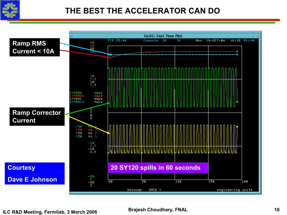
THE BEST THE ACCELERATOR CAN DO
Ramp Corrector Current
Ramp RMS Current < 10A
20 SY120 spills in 60 secondsCourtesy
Dave E Johnson
ILC R&D Meeting, Fermilab, 3 March 2006 Brajesh Choudhary, FNAL 11
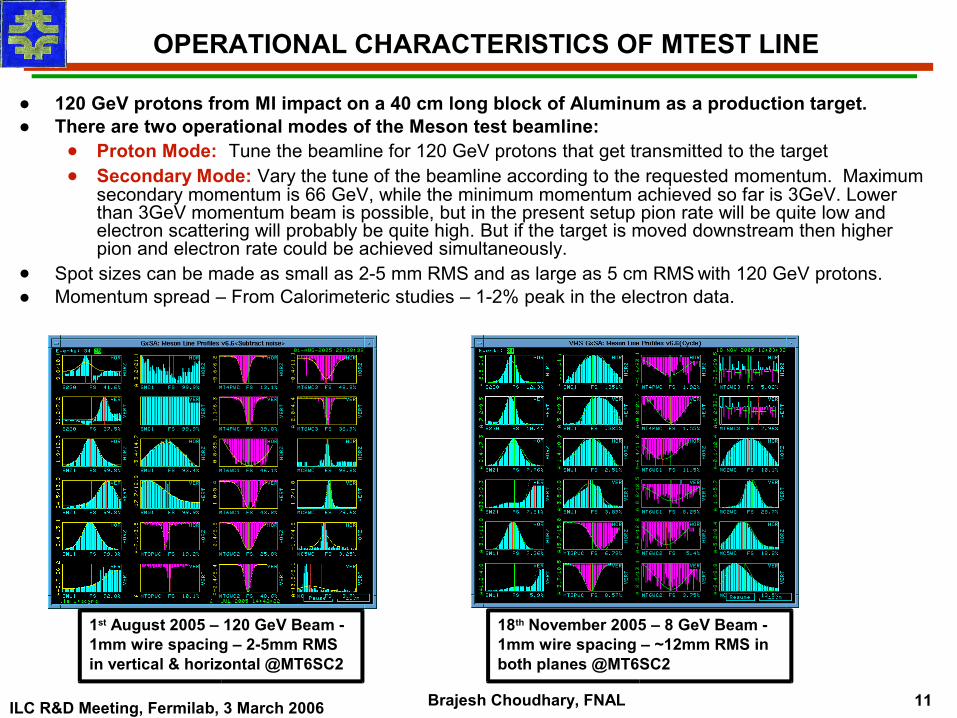
● 120 GeV protons from MI impact on a 40 cm long block of Aluminum as a production target.● There are two operational modes of the Meson test beamline:
● Proton Mode: Tune the beamline for 120 GeV protons that get transmitted to the target● Secondary Mode: Vary the tune of the beamline according to the requested momentum. Maximum
secondary momentum is 66 GeV, while the minimum momentum achieved so far is 3GeV. Lower than 3GeV momentum beam is possible, but in the present setup pion rate will be quite low and electron scattering will probably be quite high. But if the target is moved downstream then higher pion and electron rate could be achieved simultaneously.
● Spot sizes can be made as small as 2-5 mm RMS and as large as 5 cm RMS with 120 GeV protons.● Momentum spread – From Calorimeteric studies – 1-2% peak in the electron data.
OPERATIONAL CHARACTERISTICS OF MTEST LINE
1st August 2005 – 120 GeV Beam - 1mm wire spacing – 2-5mm RMS in vertical & horizontal @MT6SC2
18th November 2005 – 8 GeV Beam - 1mm wire spacing – ~12mm RMS in both planes @MT6SC2
ILC R&D Meeting, Fermilab, 3 March 2006 Brajesh Choudhary, FNAL 12
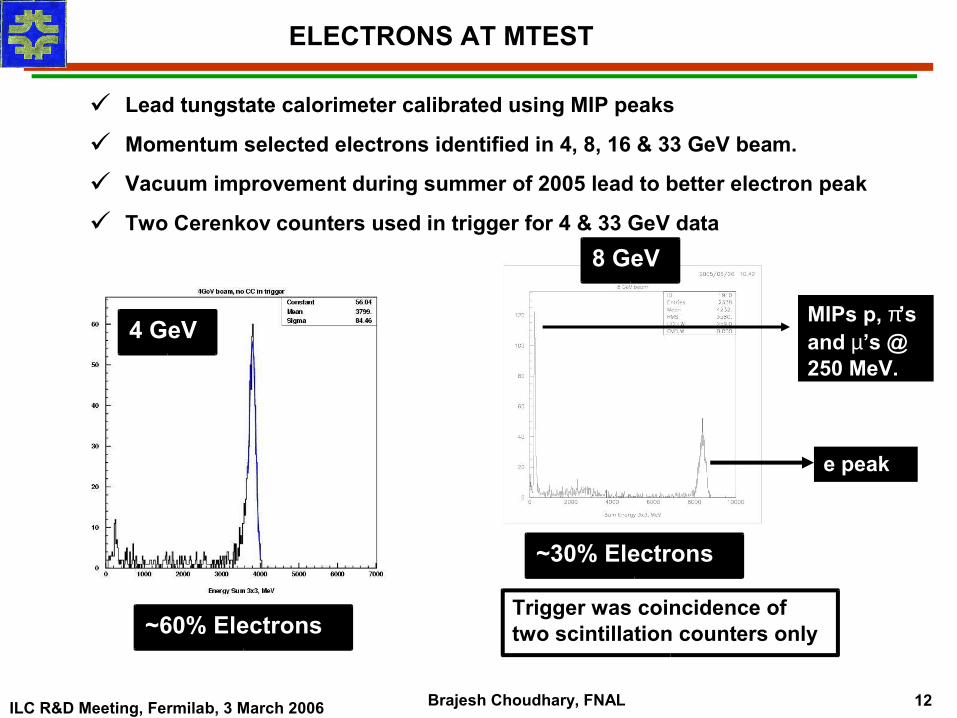
ELECTRONS AT MTEST
Lead tungstate calorimeter calibrated using MIP peaks
Momentum selected electrons identified in 4, 8, 16 & 33 GeV beam.
Vacuum improvement during summer of 2005 lead to better electron peak
Two Cerenkov counters used in trigger for 4 & 33 GeV data
~60% Electrons
~30% Electrons
Trigger was coincidence of two scintillation counters only
4 GeV
8 GeV
MIPs p, π’s and µ’s @ 250 MeV.
e peak
ILC R&D Meeting, Fermilab, 3 March 2006 Brajesh Choudhary, FNAL 13
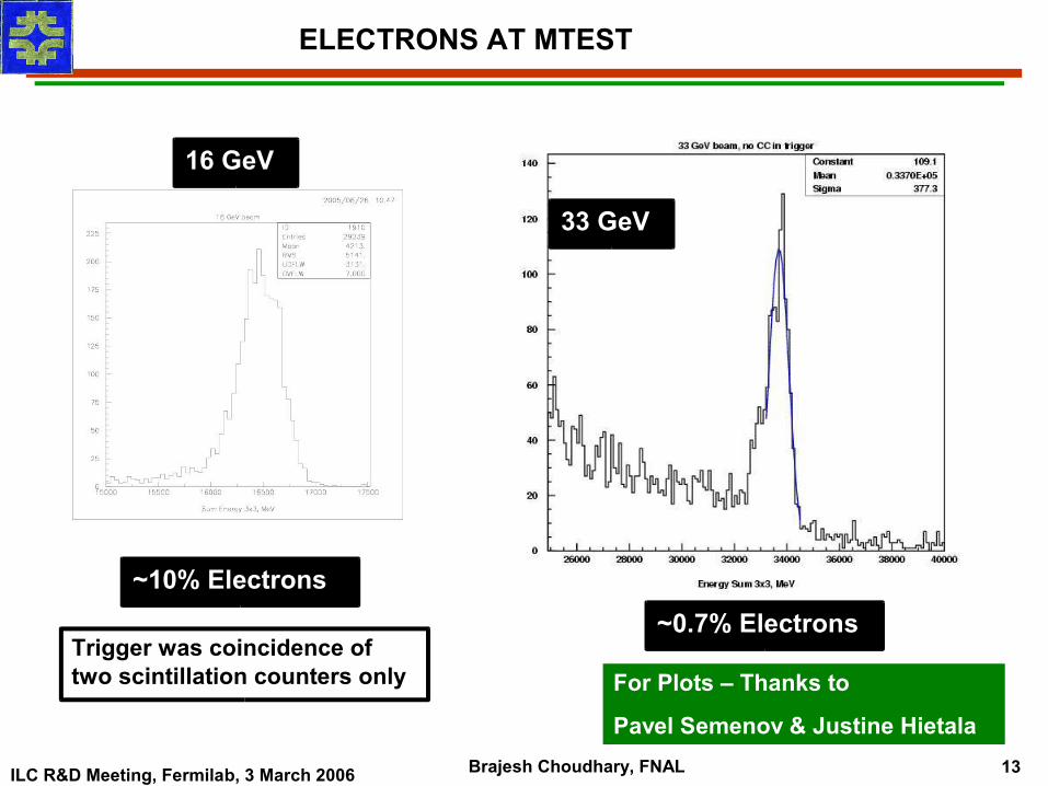
ELECTRONS AT MTEST
~10% Electrons~0.7% Electrons
16 GeV
Trigger was coincidence of two scintillation counters only
33 GeV
For Plots – Thanks to
Pavel Semenov & Justine Hietala
ILC R&D Meeting, Fermilab, 3 March 2006 Brajesh Choudhary, FNAL 14
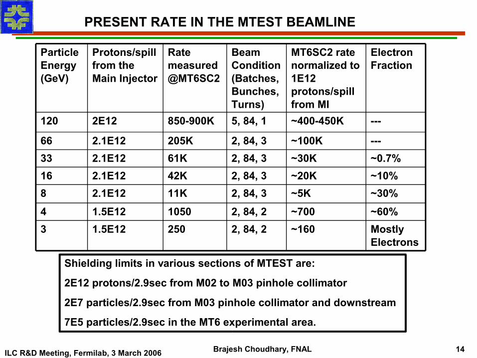
PRESENT RATE IN THE MTEST BEAMLINE
Mostly Electrons
~1602, 84, 22501.5E123~60%~7002, 84, 210501.5E124~30%~5K2, 84, 311K2.1E128~10%~20K2, 84, 342K2.1E1216~0.7%~30K2, 84, 361K2.1E1233---~100K2, 84, 3205K2.1E1266
---~400-450K5, 84, 1850-900K2E12120
Electron Fraction
MT6SC2 rate normalized to 1E12 protons/spill from MI
Beam Condition (Batches, Bunches, Turns)
Rate measured @MT6SC2
Protons/spill from the Main Injector
Particle Energy (GeV)
Shielding limits in various sections of MTEST are:
2E12 protons/2.9sec from M02 to M03 pinhole collimator
2E7 particles/2.9sec from M03 pinhole collimator and downstream
7E5 particles/2.9sec in the MT6 experimental area.
ILC R&D Meeting, Fermilab, 3 March 2006 Brajesh Choudhary, FNAL 15
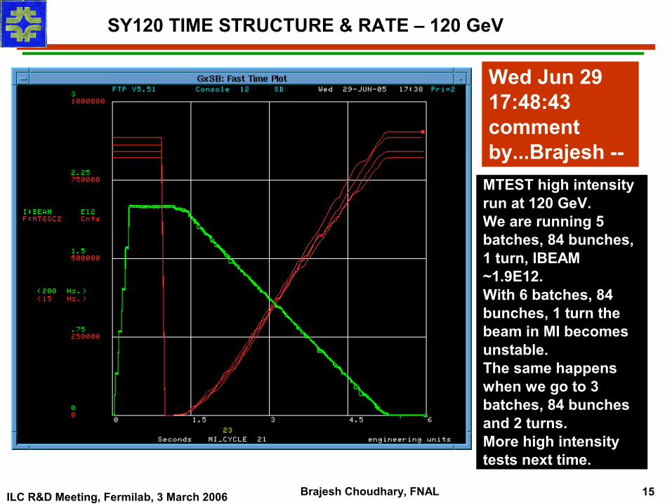
SY120 TIME STRUCTURE & RATE – 120 GeV
MTEST high intensity run at 120 GeV.We are running 5 batches, 84 bunches, 1 turn, IBEAM ~1.9E12.With 6 batches, 84 bunches, 1 turn the beam in MI becomes unstable. The same happens when we go to 3 batches, 84 bunches and 2 turns. More high intensity tests next time.
Wed Jun 29 17:48:43 comment by...Brajesh --
ILC R&D Meeting, Fermilab, 3 March 2006 Brajesh Choudhary, FNAL 16
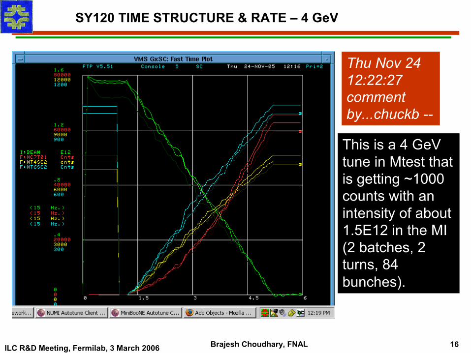
SY120 TIME STRUCTURE & RATE – 4 GeV
Thu Nov 24 12:22:27 comment by...chuckb --
This is a 4 GeV tune in Mtest that is getting ~1000 counts with an intensity of about 1.5E12 in the MI (2 batches, 2 turns, 84 bunches).
ILC R&D Meeting, Fermilab, 3 March 2006 Brajesh Choudhary, FNAL 17
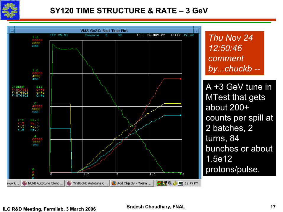
Thu Nov 24 12:50:46 comment by...chuckb --
A +3 GeV tune in MTest that gets about 200+ counts per spill at 2 batches, 2 turns, 84 bunches or about 1.5e12 protons/pulse.
SY120 TIME STRUCTURE & RATE – 3 GeV
ILC R&D Meeting, Fermilab, 3 March 2006 Brajesh Choudhary, FNAL 18
WHAT DETECTORS DO WE HAVE ?
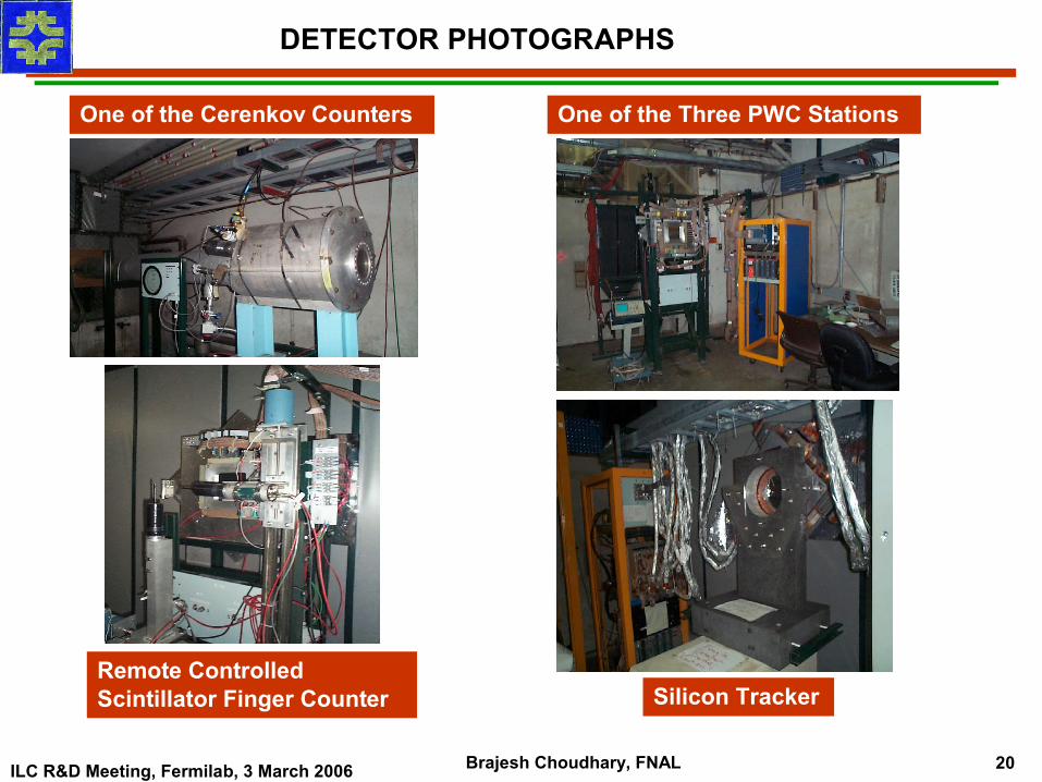
Two beamline threshold Cerenkov counters 50’ and 80’ long can be operated independently for good particle identification
One stations of X, Y silicon strip detectors are installed
One 0.5mm pitch and two 1.0mm pitch MWPC in the DAQ system
Three 1.0mm pitch MWPC into the accelerator ACNET control system
DAQ accepts custom triggers and dead time veto. The data from scintillators, Cerenkov counters, silicon and MWPC goes into an event buffers.
Buffers are readout during and after the spill and this data is accessible to experimenters. A three bit event identification is included in each event
Experimenters can add their own trigger and dead time signals.
ILC R&D Meeting, Fermilab, 3 March 2006 Brajesh Choudhary, FNAL 19
Finger countersPWCScintillator SSDSWIC
MTEST BEAM FACILITY DETECTORS
1.0 mm0.5 mm
ILC R&D Meeting, Fermilab, 3 March 2006 Brajesh Choudhary, FNAL 20
One of the Cerenkov Counters One of the Three PWC Stations
Remote Controlled Scintillator Finger Counter Silicon Tracker
DETECTOR PHOTOGRAPHS
ILC R&D Meeting, Fermilab, 3 March 2006 Brajesh Choudhary, FNAL 21
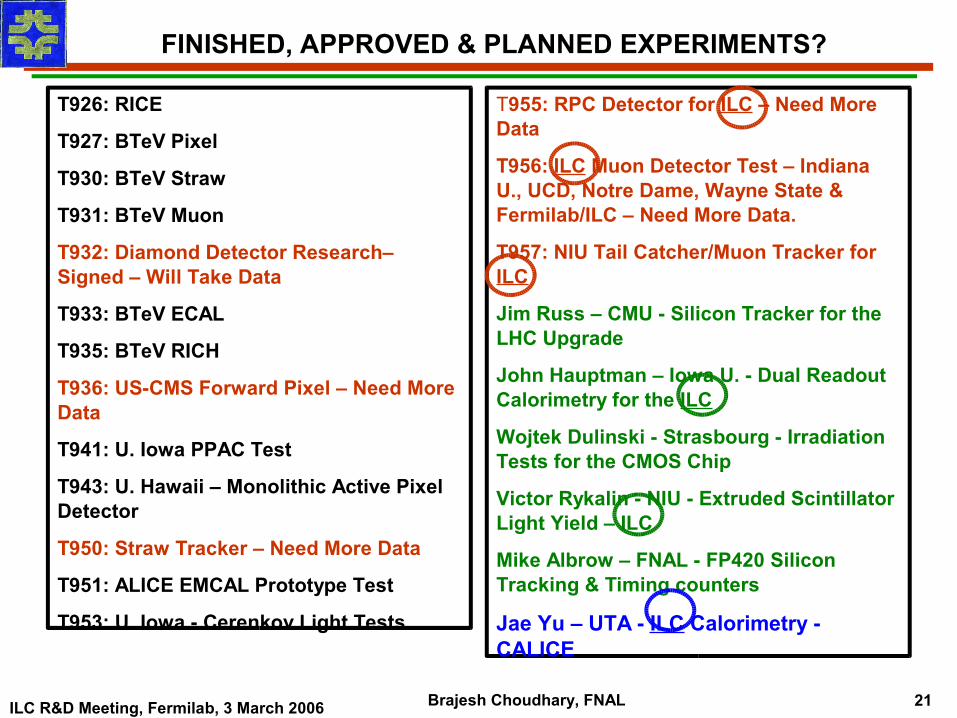
T955: RPC Detector for ILC – Need More Data
T956: ILC Muon Detector Test – Indiana U., UCD, Notre Dame, Wayne State & Fermilab/ILC – Need More Data.
T957: NIU Tail Catcher/Muon Tracker for ILC
Jim Russ – CMU - Silicon Tracker for the LHC Upgrade
John Hauptman – Iowa U. - Dual Readout Calorimetry for the ILC
Wojtek Dulinski - Strasbourg - Irradiation Tests for the CMOS Chip
Victor Rykalin - NIU - Extruded Scintillator Light Yield – ILC
Mike Albrow – FNAL - FP420 Silicon Tracking & Timing counters
Jae Yu – UTA - ILC Calorimetry - CALICE
FINISHED, APPROVED & PLANNED EXPERIMENTS?
T926: RICE
T927: BTeV Pixel
T930: BTeV Straw
T931: BTeV Muon
T932: Diamond Detector Research– Signed – Will Take Data
T933: BTeV ECAL
T935: BTeV RICH
T936: US-CMS Forward Pixel – Need More Data
T941: U. Iowa PPAC Test
T943: U. Hawaii – Monolithic Active Pixel Detector
T950: Straw Tracker – Need More Data
T951: ALICE EMCAL Prototype Test
T953: U. Iowa - Cerenkov Light Tests
ILC R&D Meeting, Fermilab, 3 March 2006 Brajesh Choudhary, FNAL 22
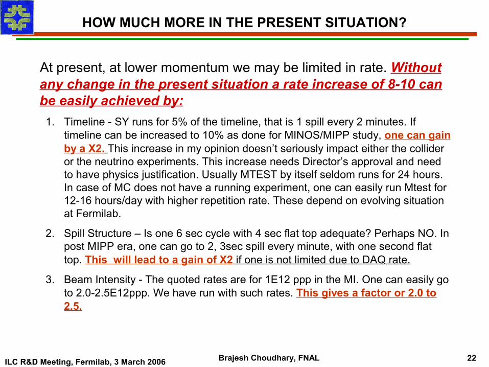
HOW MUCH MORE IN THE PRESENT SITUATION?
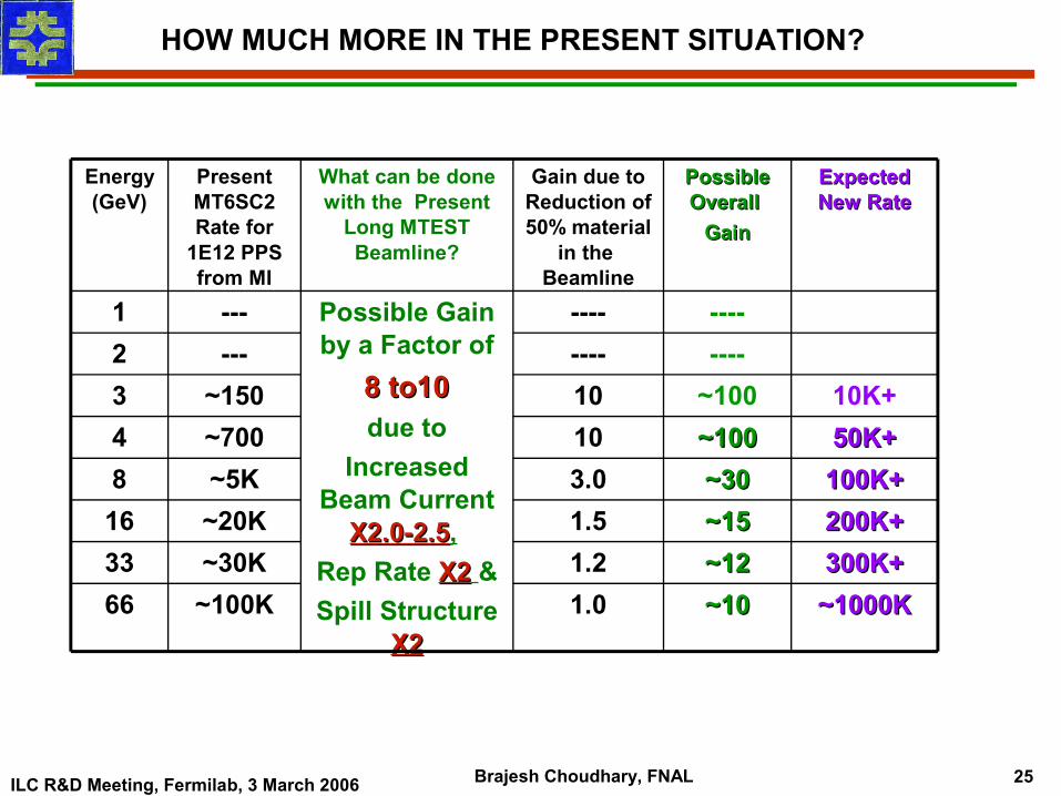
At present, at lower momentum we may be limited in rate. Without any change in the present situation a rate increase of 8-10 can be easily achieved by:
1. Timeline - SY runs for 5% of the timeline, that is 1 spill every 2 minutes. If timeline can be increased to 10% as done for MINOS/MIPP study, one can gain by a X2. This increase in my opinion doesn’t seriously impact either the collider or the neutrino experiments. This increase needs Director’s approval and need to have physics justification. Usually MTEST by itself seldom runs for 24 hours. In case of MC does not have a running experiment, one can easily run Mtest for 12-16 hours/day with higher repetition rate. These depend on evolving situation at Fermilab.
2. Spill Structure – Is one 6 sec cycle with 4 sec flat top adequate? Perhaps NO. In post MIPP era, one can go to 2, 3sec spill every minute, with one second flat top. This will lead to a gain of X2 if one is not limited due to DAQ rate.
3. Beam Intensity - The quoted rates are for 1E12 ppp in the MI. One can easily go to 2.0-2.5E12ppp. We have run with such rates. This gives a factor or 2.0 to 2.5.
ILC R&D Meeting, Fermilab, 3 March 2006 Brajesh Choudhary, FNAL 23
ISSUES WITH THE PRESENT SITUATION
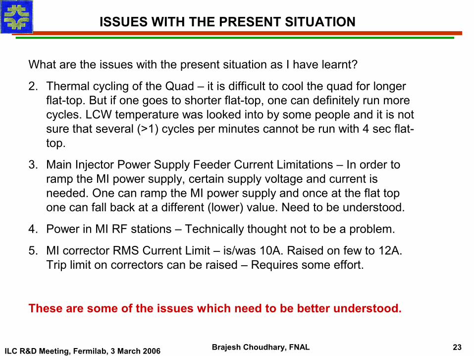
What are the issues with the present situation as I have learnt?
2. Thermal cycling of the Quad – it is difficult to cool the quad for longer flat-top. But if one goes to shorter flat-top, one can definitely run more cycles. LCW temperature was looked into by some people and it is not sure that several (>1) cycles per minutes cannot be run with 4 sec flat-top.
3. Main Injector Power Supply Feeder Current Limitations – In order to ramp the MI power supply, certain supply voltage and current is needed. One can ramp the MI power supply and once at the flat top one can fall back at a different (lower) value. Need to be understood.
4. Power in MI RF stations – Technically thought not to be a problem.
5. MI corrector RMS Current Limit – is/was 10A. Raised on few to 12A. Trip limit on correctors can be raised – Requires some effort.
These are some of the issues which need to be better understood.
ILC R&D Meeting, Fermilab, 3 March 2006 Brajesh Choudhary, FNAL 24
GAIN FROM REDUCING MATERIAL IN THE PRESENT MTEST BEAMLINE
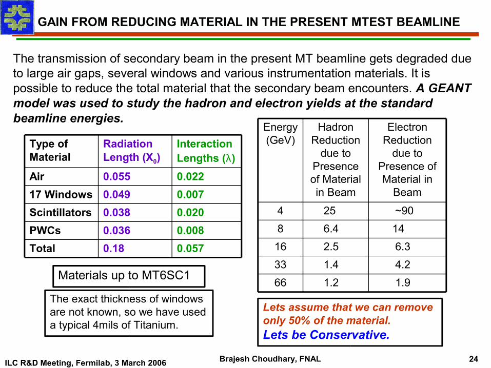
The transmission of secondary beam in the present MT beamline gets degraded due to large air gaps, several windows and various instrumentation materials. It is possible to reduce the total material that the secondary beam encounters. A GEANT model was used to study the hadron and electron yields at the standard beamline energies.
0.0570.18Total0.0080.036PWCs0.0200.038Scintillators0.0070.04917 Windows0.0220.055Air
Interaction Lengths (λ)
Radiation Length (X0)
Type of Material
The exact thickness of windows are not known, so we have used a typical 4mils of Titanium.
Materials up to MT6SC1 1.9 1.2 664.2 1.4 336.3 2.5 1614 6.4 8~90 25 4
Electron Reduction
due to Presence of Material in
Beam
Hadron Reduction
due to Presence of Material in Beam
Energy (GeV)
Lets assume that we can remove only 50% of the material. Lets be Conservative.
ILC R&D Meeting, Fermilab, 3 March 2006 Brajesh Choudhary, FNAL 25
HOW MUCH MORE IN THE PRESENT SITUATION?
~10~10~12~12~15~15~30~30~100~100~100--------
Possible Possible Overall Overall
GainGain
Possible Gain by a Factor of
8 to108 to10 due to
Increased Beam Current
X2.0-2.5X2.0-2.5, Rep Rate X2X2 &Spill Structure
X2X2
What can be done with the Present
Long MTEST Beamline?
-------1
~100K~30K~20K~5K~700~150
---
Present MT6SC2 Rate for
1E12 PPS from MI
1.01.21.53.01010----
Gain due to Reduction of 50% material
in the Beamline
~1000K~1000K66300K+300K+33200K+200K+16100K+100K+850K+50K+410K+3
2
Expected Expected New RateNew Rate
Energy (GeV)
ILC R&D Meeting, Fermilab, 3 March 2006 Brajesh Choudhary, FNAL 26
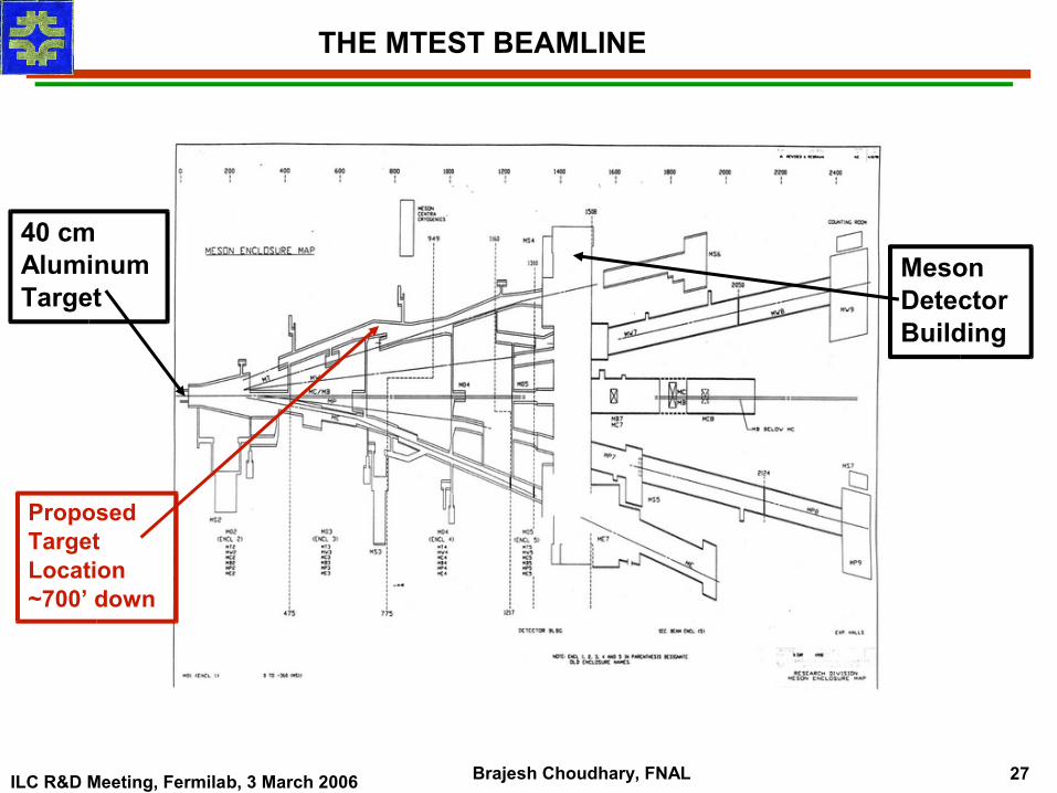
SCHEMATIC DIAGRAM OF THE MTEST BEAMLINE
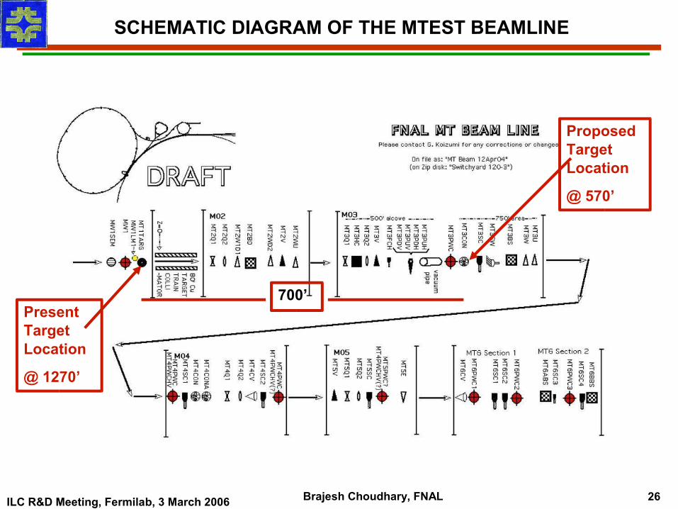
Present Target Location
@ 1270’
Proposed Target Location
@ 570’
700’
ILC R&D Meeting, Fermilab, 3 March 2006 Brajesh Choudhary, FNAL 27
40 cm Aluminum Target
Meson Detector Building
Proposed Target Location ~700’ down
THE MTEST BEAMLINE
ILC R&D Meeting, Fermilab, 3 March 2006 Brajesh Choudhary, FNAL 28
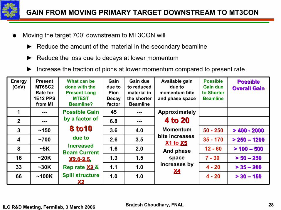
GAIN FROM MOVING PRIMARY TARGET DOWNSTREAM TO MT3CON
● Moving the target 700’ downstream to MT3CON will
► Reduce the amount of the material in the secondary beamline
► Reduce the loss due to decays at lower momentum
► Increase the fraction of pions at lower momentum compared to present rate
4 - 204 - 207 - 30 12 - 60
35 - 17050 - 250
Possible Gain due to Shorter Beamline
Possible Gain by a factor of
8 to108 to10 due to
Increased Beam Current
X2.0-2.5X2.0-2.5, Rep rate X2X2 &Spill structure
X2X2
What can be done with the Present Long
MTEST Beamline?
---45---1
~100K~30K~20K~5K~700~150
---
Present MT6SC2 Rate for
1E12 PPS from MI
Approximately 4 to 204 to 20
Momentum bite increases
X1 to X5X5 And phase
space increases by
X4X4
Available gain due to
momentum bite and phase space
1.01.01.52.03.54.0---
Gain due to reduced material in the shorter Beamline
> 30 – 150> 30 – 1501.066> 35 – 200> 35 – 2001.133> 50 – 250> 50 – 2501.316
> 100 – 500> 100 – 5001.68> 250 – 1200> 250 – 12002.64> 400 - 2000> 400 - 20003.63
6.82
Possible Possible Overall GainOverall Gain
Gain due to Pion
Decay factor
Energy (GeV)
ILC R&D Meeting, Fermilab, 3 March 2006 Brajesh Choudhary, FNAL 29
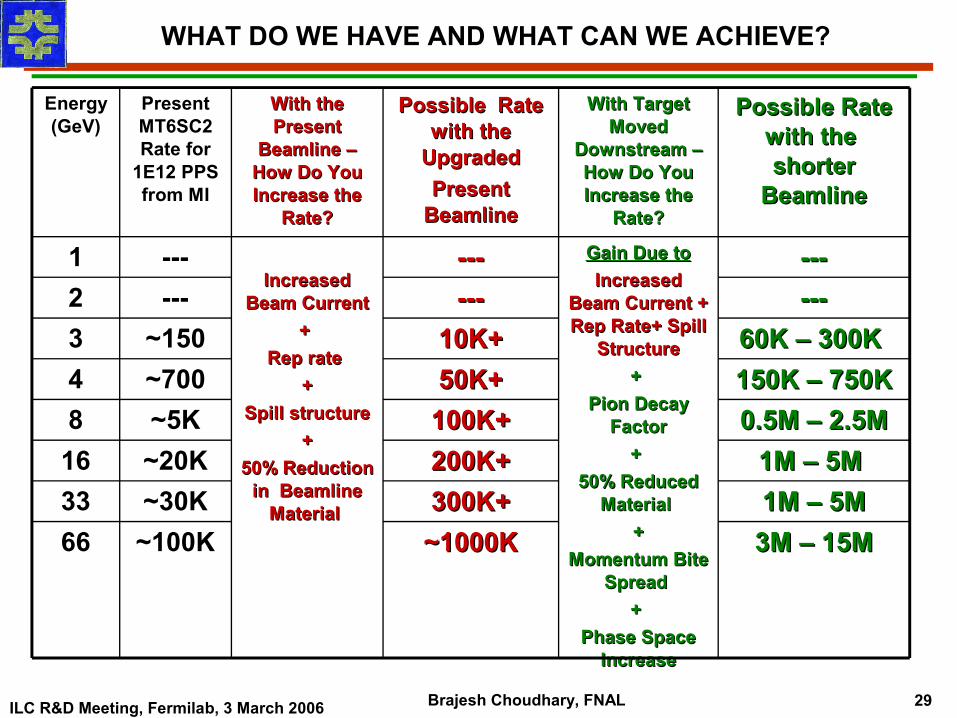
WHAT DO WE HAVE AND WHAT CAN WE ACHIEVE?
3M – 15M3M – 15M1M – 5M1M – 5M1M – 5M 1M – 5M
0.5M – 2.5M0.5M – 2.5M150K – 750K150K – 750K60K – 300K 60K – 300K
------------
Possible Rate Possible Rate with the with the shorter shorter
BeamlineBeamline
Increased Increased Beam CurrentBeam Current
+ + Rep rate Rep rate
++Spill structureSpill structure
++50% Reduction 50% Reduction
in Beamline in Beamline Material Material
With the With the Present Present
Beamline – Beamline – How Do You How Do You Increase the Increase the
Rate?Rate?
Gain Due toGain Due toIncreased Increased
Beam Current + Beam Current + Rep Rate+ Spill Rep Rate+ Spill
StructureStructure+ +
Pion Decay Pion Decay FactorFactor
+ + 50% Reduced 50% Reduced
Material Material ++
Momentum Bite Momentum Bite Spread Spread
+ + Phase Space Phase Space
IncreaseIncrease
---------1
~100K~30K~20K~5K~700~150
---
Present MT6SC2 Rate for
1E12 PPS from MI
With Target With Target Moved Moved
Downstream – Downstream – How Do You How Do You Increase the Increase the
Rate?Rate?
~1000K~1000K66300K+300K+33200K+200K+16100K+100K+850K+50K+410K+10K+3
------2
Possible Rate Possible Rate with the with the
UpgradedUpgradedPresent Present
BeamlineBeamline
Energy (GeV)
ILC R&D Meeting, Fermilab, 3 March 2006 Brajesh Choudhary, FNAL 30
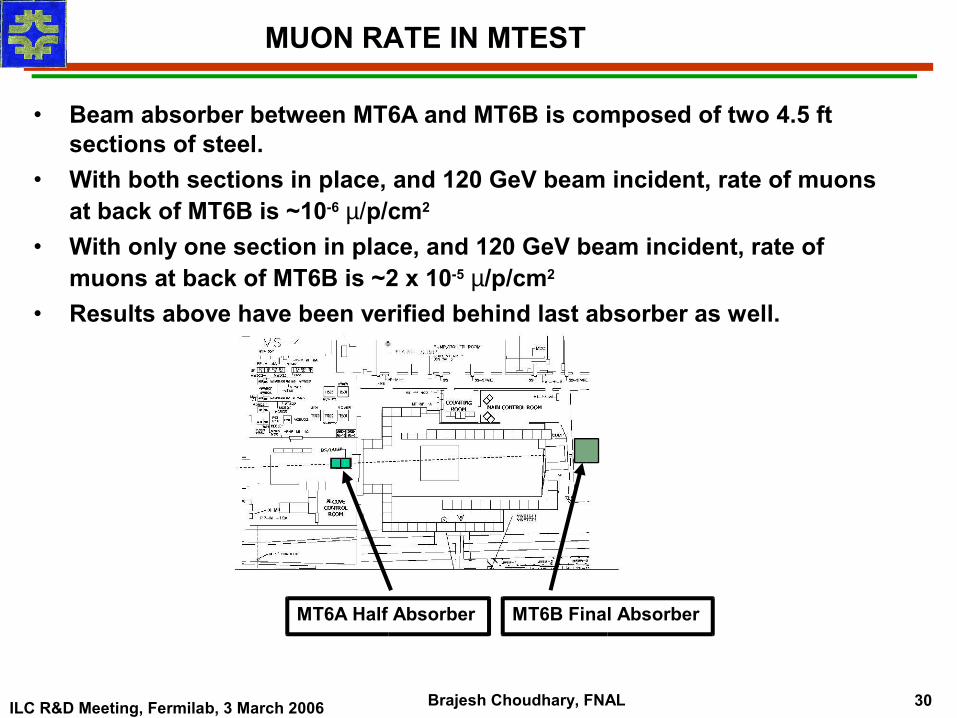
MT6A Half Absorber MT6B Final Absorber
MUON RATE IN MTEST
• Beam absorber between MT6A and MT6B is composed of two 4.5 ft sections of steel.
• With both sections in place, and 120 GeV beam incident, rate of muons at back of MT6B is ~10-6 µ/p/cm2
• With only one section in place, and 120 GeV beam incident, rate of muons at back of MT6B is ~2 x 10⁻⁵ µ/p/cm2
• Results above have been verified behind last absorber as well.
ILC R&D Meeting, Fermilab, 3 March 2006 Brajesh Choudhary, FNAL 31
MESON CENTER AS THE TEST BEAM OPTION
MCenter is currentlyunscheduled. A number of
possible uses, including test beam use, have
been suggested. Decisions will depend on proposals,
scheduling, funding,and priorities at the time
that decisions will need to be made.
MCENTER is a relatively smaller beam line and hence the rates are higher compared to MTEST. Particles up to
momentum of 1 GeV has been measured.
ILC R&D Meeting, Fermilab, 3 March 2006 Brajesh Choudhary, FNAL 32
TEST BEAM FOR LHC, NOυA, MINERυA & THE ILC
LHC – The Last Hadron Collider? You don’t need me to tell you about the LHC but they do use Fermilab’s test beam facility.
NOυA is a Fermilab experiment to measure sub-dominant νµ→νe
oscillation and thus θ13, matter effect or hierarchy, and the CP violating phase δ in the lepton sector in a staged manner using a 30 KTon totally active liquid scintillator detector situated ~810 Km from Fermilab and ~12-15 Kms Off-Axis of the NuMI ν (and anti-ν) beam. NOυA will have a 212 Tons fully active movable near detector to measure νe content of the beam, characterize detector response to neutrino events & perform crucial background studies.
MINERυA is a high statistics, high-resolution ν and anti-ν nucleon/nucleus scattering experiment to measure neutrino cross-section and probe nuclear effects essential to present and future neutrino-oscillation experiments. It will use ν and anti-ν beam from NuMI and a fully active 8.3 Tons target scintillator detector surrounded by sampling EMCAL, HCAL, and a muon system, located 1.5m upstream of the MINOS Near Detector in the MINOS hall.
ILC – International Linear Collider.
ILC R&D Meeting, Fermilab, 3 March 2006 Brajesh Choudhary, FNAL 33
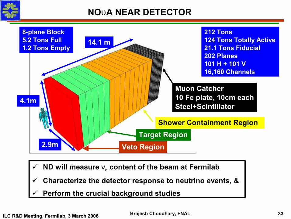
NOυA NEAR DETECTOR
8-plane Block5.2 Tons Full1.2 Tons Empty
14.1 m
4.1m
2.9m
212 Tons124 Tons Totally Active21.1 Tons Fiducial202 Planes101 H + 101 V16,160 Channels
Muon Catcher10 Fe plate, 10cm eachSteel+Scintillator
Shower Containment RegionTarget Region
Veto Region
ND will measure νe content of the beam at Fermilab
Characterize the detector response to neutrino events, & Perform the crucial background studies
ILC R&D Meeting, Fermilab, 3 March 2006 Brajesh Choudhary, FNAL 34
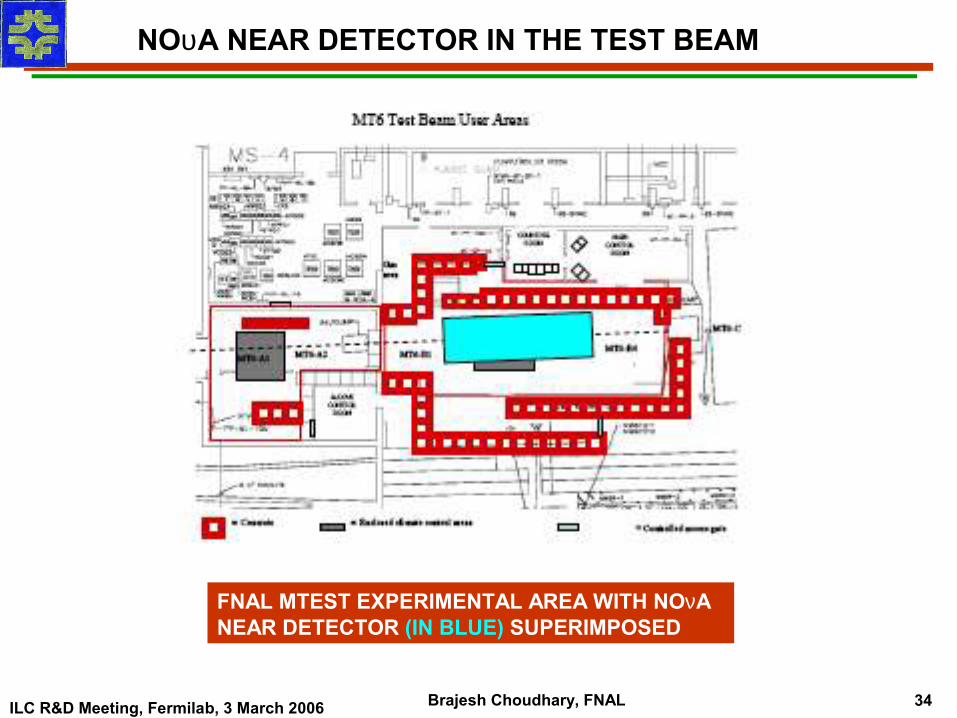
NOυA NEAR DETECTOR IN THE TEST BEAM
FNAL MTEST EXPERIMENTAL AREA WITH NOνA NEAR DETECTOR (IN BLUE) SUPERIMPOSED
ILC R&D Meeting, Fermilab, 3 March 2006 Brajesh Choudhary, FNAL 35
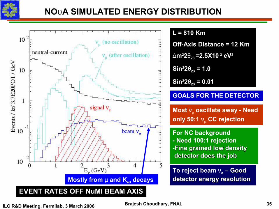
NOυA SIMULATED ENERGY DISTRIBUTION
Mostly from µ and Ke3 decays
L = 810 Km
Off-Axis Distance = 12 Km
∆m22θ23 =2.5X10⁻³ eV2
Sin22θ23 = 1.0
Sin22θ23 = 0.01
GOALS FOR THE DETECTOR
Most νµ oscillate away - Need only 50:1 νµ CC rejection
For NC background - Need 100:1 rejection -Fine grained low density Fine grained low density detector does the jobdetector does the job
To reject beam νe – Good Good detector energy resolutiondetector energy resolution
EVENT RATES OFF NuMI BEAM AXIS
ILC R&D Meeting, Fermilab, 3 March 2006 Brajesh Choudhary, FNAL 36
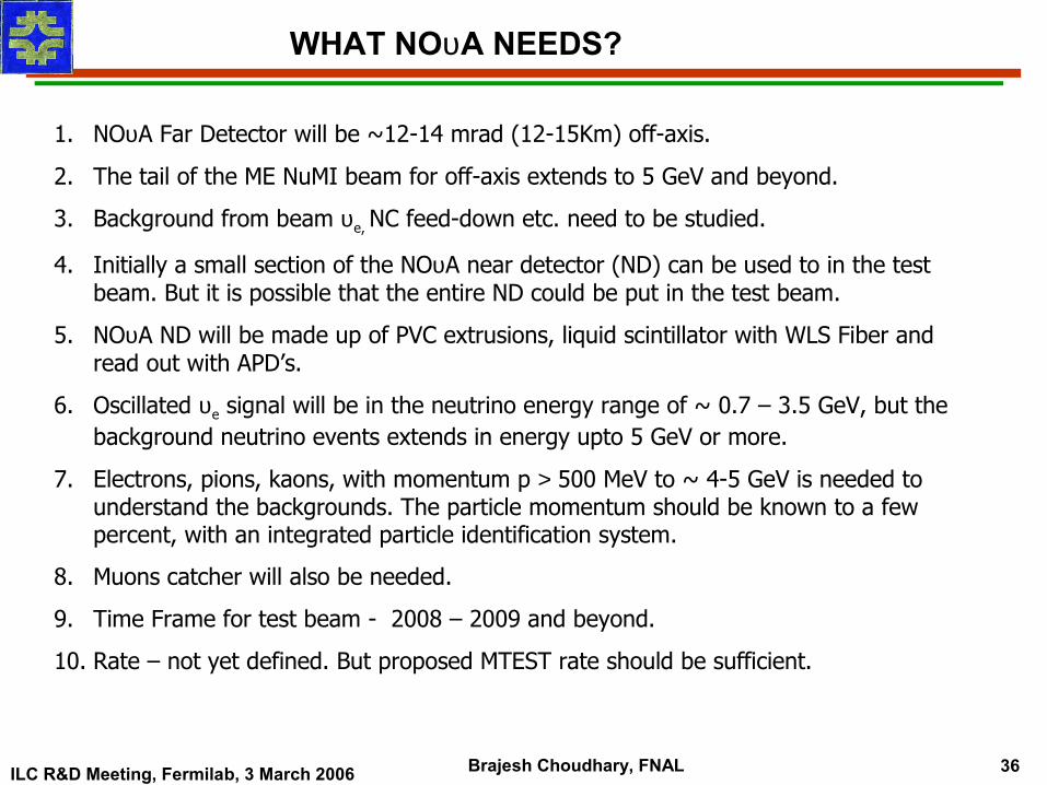
WHAT NOυA NEEDS?
1. NOυA Far Detector will be ~12-14 mrad (12-15Km) off-axis.
2. The tail of the ME NuMI beam for off-axis extends to 5 GeV and beyond.
3. Background from beam υe, NC feed-down etc. need to be studied.
4. Initially a small section of the NOυA near detector (ND) can be used to in the test beam. But it is possible that the entire ND could be put in the test beam.
5. NOυA ND will be made up of PVC extrusions, liquid scintillator with WLS Fiber and read out with APD’s.
6. Oscillated υe signal will be in the neutrino energy range of ~ 0.7 – 3.5 GeV, but the background neutrino events extends in energy upto 5 GeV or more.
7. Electrons, pions, kaons, with momentum p > 500 MeV to ~ 4-5 GeV is needed to understand the backgrounds. The particle momentum should be known to a few percent, with an integrated particle identification system.
8. Muons catcher will also be needed.
9. Time Frame for test beam - 2008 – 2009 and beyond.
10. Rate – not yet defined. But proposed MTEST rate should be sufficient.
ILC R&D Meeting, Fermilab, 3 March 2006 Brajesh Choudhary, FNAL 37
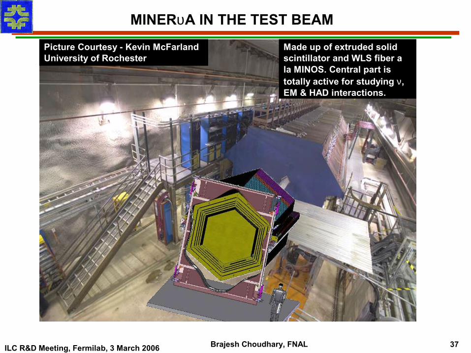
MINERυA IN THE TEST BEAM
Picture Courtesy - Kevin McFarland University of Rochester
Made up of extruded solid scintillator and WLS fiber a la MINOS. Central part is totally active for studying ν, EM & HAD interactions.
ILC R&D Meeting, Fermilab, 3 March 2006 Brajesh Choudhary, FNAL 38
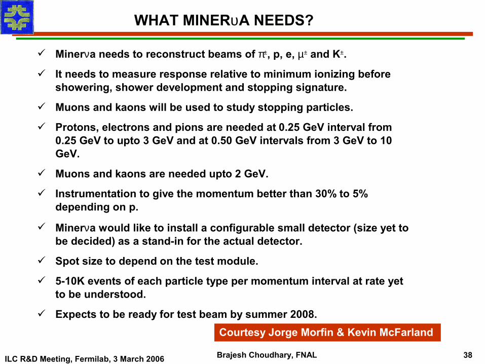
WHAT MINERυA NEEDS?
Minerνa needs to reconstruct beams of π±, p, e, µ± and K±.
It needs to measure response relative to minimum ionizing before showering, shower development and stopping signature.
Muons and kaons will be used to study stopping particles.
Protons, electrons and pions are needed at 0.25 GeV interval from 0.25 GeV to upto 3 GeV and at 0.50 GeV intervals from 3 GeV to 10 GeV.
Muons and kaons are needed upto 2 GeV.
Instrumentation to give the momentum better than 30% to 5% depending on p.
Minerνa would like to install a configurable small detector (size yet to be decided) as a stand-in for the actual detector.
Spot size to depend on the test module.
5-10K events of each particle type per momentum interval at rate yet to be understood.
Expects to be ready for test beam by summer 2008. Courtesy Jorge Morfin & Kevin McFarland
ILC R&D Meeting, Fermilab, 3 March 2006 Brajesh Choudhary, FNAL 39
WHAT ILC WILL NEED?
ILC will need electrons, pions, hadrons and muons at various momenta.
Pions, hadrons and electrons of momenta 1 GeV and above will be needed.
Test with high energy electrons can be done at DESY, SLAC or CERN as CALICE has done.
We already provide electrons, pions, protons at a reasonable rate upto momenta of 3 GeV and above.
We are hopeful that we can go to a momenta of 2 GeV and below.
It is our understanding that good rate for electrons, pions, and hadrons from very low momenta (~1 GeV) to high momenta should be available after the Mtest beamline upgrade.
ILC R&D Meeting, Fermilab, 3 March 2006 Brajesh Choudhary, FNAL 40
SUMMARY & CONCLUSIONS
1. MTest has successfully delivered and continues to deliver beam of various momentum to CMS pixel, ALICE, and PHENIX EMCAL, other test detector groups, including ILC RPC, muon tracker etc.
2. NOυA will need low energy electrons, pions, and hadrons.
3. MINERυA will like to reconstruct 0.3 - 5GeV energy pions and electrons, 1-5 GeV protons, and kaons/muons to study stopping particles.
4. In future we expect the ILC to be the major test beam user. ILC will need low energy pions, hadrons, electrons/positrons, and muons.
5. Studies are ongoing to upgrade the MTest beam line with the possibility of going down to lower momentum (~1GeV and below) and to have a reasonably good rate for electrons, pions and hadrons at all energies.
6. It is definitely possible to increase the particle yield at very low momenta by a factor of ~1000 or more.
7. We welcome the larger international community, especially the ILC world. COME TO FERMILAB.