Embed Size (px)
Citation preview
C-,
C- R 5
Technical Report ii!!ii-ii::ii!..::.-.*..i..*.*....:: HEAT-TRANSFER STUDIES OF DROPWISE......... .. ... .....--
... iC.O.N.D.E N S ATION AND THIN-FILM
...........EVAPORATION
30 June 1963
.... JUL~
LL.
U. S. NAVAL CIVIL ENGINEERING LABORATORY
Port Hueneme, California
410566
looooiii~iiiiiiiiiiiiiiiN am:'':,..:::'..,..,

HEAT-TRANSFER STUDIES OF DROPWISE CONDENSATION AND THIN-FILM
EVA PORAT ION
Y-RO11-01-009
Type C Final Report
by
C. Saturnino
ABSTRACT
Experiments were conducted to investigate heat-transfer rates from water-filmevaporation and dropwise condensation. Dropwise condensation was induced bycoating the external surface of the heat-exchanger tubes with a polytetrafluoro-ethylene polymer, and film evaporation was obtained by allowing water to fall ina thin film around the surface of the tube. The effect of tube length and feed flowon the overall heat-transfer coefficient was also investigated. The overall heat-transfer coefficients obtained from the dropwise condensation experiments wereconsiderably greater than those obtained from the film-type condensation experimentsconducted to obtain comparison data. Overall heat-transfer coefficients as high as4000 Btu/sq ft/F/hr were obtained from the dropwise condensation experiments ascompared to values of about 700 Btu/sq ft/F/hr that were obtained from the film-typecondensation. The results of thin-film evaporation on the internal surface of the tubewere inconclusive.
Qualified requesters may obtain copies of this report from ASTIA.The Laboratoiy invites comment on this report, particularly on the
results obtained by those who have applied the information.

INTRODUCTION
The total quantity of heat transferred in evaporators may be affected bychanges in temperature drop or by changes in the overall coefficient. The overallcoefficient is affected by changes in the steam-film coefficient and the liquid-filmcoefficient. Although the mechanism of heat transfer in the liquid film is verycomplex and very little data is available, three principal factors that affect it areknown:l1 (1) the velocity of the liquid past the heating surface, (2) the viscosity ofthe liquid, and (3) the geometrical arrangement and condition of the heating surface.
The mechanism of heat transfer in the steam film is better known than thatfor the liquid film. When the steam condenses on a metal surface, the condensationmay take place in either of two forms. One of the forms is known as film-typecondensation, which occurs when the steam wets the surface on which it is condensing.The other is known as dropwise condensation, which occurs when the steam does notwet the surface on which it is condensing but collects in the form of drops that falloff the surface, leaving an apparently unwetted surface where new drops can form.The steam-film coefficients obtained from dropwise condensation are larger thanthose obtained from film-type condensation.
Both forms of condensation may take place at the same time, but, in general,smooth clean surfaces tend to induce film-type condensation, and oily or greasysurfaces tend to induce dropwise condensation. The use of oily or greasy materialsis not very practical because they are washed away and have to be replaced con-tinuously, and, in most cases, they impart undesirable odor and taste to the distilledwater. 2
Since the overall heat-transfer coefficient is affected by changes in thesteam- and water-film coefficients, the experimental work was directed towardthe investigation of overall heat coefficients, combining the effects of dropwisecondensation and water-film evaporation.
For this task, a polytetrafluoroethylene polymer 2 was selected to inducedropwise condensation because it does not wet nor wash away. Water-filmevaporation was obtained from a thin film of water falling on the surface of avertical tube.

DESCRIPTION OF EQUIPMENT
The experimental work was made in two vertical evaporators: a single-tubeunit and a multiple-tube unit. Two test series were made on single-tube units andone series on the multiple-tube unit.
The single-tube evaporator had a 1-inch-OD, 16-BWG, cupro-nickel tubemounted inside a shell of 3-inch glass pipe sections. The length of the tube wasmade a variable parameter for these runs. Figures 1 and 2 show the single-tubeevaporator at its maximum length. For one series of runs, the top section of theevaporator was adapted with an orifice plate to produce a thin film of water fall-ing on the external surface of the tube (Figure 3 is the flow diagram). For the otherseries of runs, the top section of the evaporator was adapted with an orifice providedwith a plug that projected into the tube, leaving an annular space from which waterran down on the internal surface of the tube in the form of a thin film (Figure 4 isthe flow diagram). There were no means to ascertain that the water inside the tubewas actually flowing in the form of a thin film, but, for practical purposes, it wasassumed.
The steam for this single-tube apparatus was supplied by an oil-fired steamgenerator. The pressure of the steam from the generator was reduced to about3.0 psig by a pressure-reducing valve in the inlet side of tha evaporator. The feed-water was preheated with steam in a shell-and-tube heat exchanger. The feed flowwas controlled by a float-valve in a variable-hydraulic-head storage tank.
In setting up the single-tube apparatus, some difficulty was encountered incontrolling the thickness of the film falling on the external surface of the tube.The apparatus used for this is shown in Figure 5. An orifice was used at the top ofthe tube, and the hydraulic head on the orifice was varied to change the thicknessof the water film. A 1-1/16-inch orifice plate produced the most uniform coverageand film thickness for the purpose of the investigation. For the falling film on theinternal surface of the tube, an orifice plate was adapted, with a plug that projectedabout 0.75 inch down the opening of the tube to form an annular space about1/16 inch wide within the tube.
The multiple-tube evaporator, a shell-and-tube unit, consisted of thirty-seven1-inch-OD, 10-foot-long, 16-BWG, cupro-nickel tubes and a steel shell. Theexteriors of the tubes were coated thinly with a polytetrafluoroethylene polymer;the thickness of the coat averaged about 0.001 inch. The evaporator was operatedas a thermocompression unit by using the components (except for the evaporator body)of an 85-gph distillation unit. Figure 6 shows the 37-tube evaporator, the dieselengine, and: the compressor.
2

EXPERIMENTAL RUNS WITH THE SINGLE-TUBE EVAPORATOR
The first series of runs was maide on a single, bare tube. The falling film wason the external surface of the tube, and the heating steam was inside the tube.
The second series of runs was made on a single, coated-exterior tube. Thefalling film was on the internal surface of the tube and the heating steam condensedon the external, coated surface of the tube. A run was also made on this evaporatorwith the tube stripped of the coating.
During these two series, the length of the tube was varied, by cutting sectionsof different lengths, to determine the effect of tube length on the overall heat-transfercoefficient.
Distilled water was used for all tests. The temperature of the water flows wereread from thermometers inserted in the flow lines entering and leaving the evaporator.The temperatures of the steam and evaporating water were obtained from steam tables3
by using the pressure readings in the steam side and in the evaporating water side ofthe evaporator.
Constant operating conditions were maintained for the duration of each run,except that during the first series of runs, the temperature of the feed could not bekept constant. The variation in temperature was due to fluctuations in the steamflow entering the feed heater. In the subsequent series of runs no attempt was madeto obtain a definite feed temperature below 212 F. Figure 7 shows the results of thefirst series with the bare tube and a falling film on the outside of the tube. Theoverall heat-transfer coefficient is plotted against the feed flow rates and tubelengths.
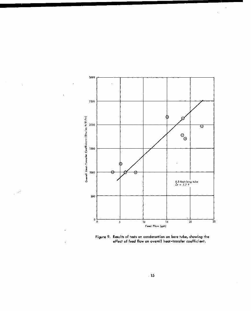
The second series of runs was conducted under similar operating conditionsbut with the film evaporation on the internal surface of the tube and steam conden-sation on the external surface of the tube. Figure 8 shows the overall heat-transfercoefficient plotted against the feed flow rates and tube lengths for dropwisecondensation on the coated surface, and Figure 9 shows the coefficients for filmcondensation on the uncoated surface of the tube.
EXPERIMENTAL RUNS WITH THE 37-TUBE EVAPORATOR
A series of runs was made in the 37-tube evaporator, with all the tubes coatedexternally with the polytetrafluoroethylene polymer. For these experiments, thelength of the tubes was constant, the falling film was on the internal surface of thetube, and the heating steam was on the external surface of the tube.
3

For these runs, the tubes were partially filled with water, and attempts weremade to run the tests with falling film alone, but feedwater could not be distributeduniformly to all the tubes. Figure 10 shows the overall heat-transfer coefficientplotted against water level and compressor speed.
RESULTS
The overall heat coefficients obtained from the 37-tube-unit runs were in thesame order of magnitude as those obtained from the single bare-tube unit. However,it was apparent that in the 37-tube unit, only a fraction of the heat transfer wastaking place from the condensing steam to the falling film since not all the tubeswere wetted by the falling water. The overall heat-transfer coefficients obtainedfrom the single, coated tube with dropwise condensation were considerably greaterthan those obtained from the other runs.
The overall heat-transfer coefficients for the single, bare tube ranged from450 to 700 Btu/sq ft/F/hr, with feed flows of 5 to 30 gph and tube lengths from4.5 to 8.0 feet. For the single, coated tube, the coefficients ranged from 1000 to4000 Btu/sq ft/F/hr with feed flows of 8.0 to 26.0 gph and tube lengths from 2.5 to8.5 feet. The highest coefficient was obtained from the shortest tube length andthe highest feed flow rate.
The overall heat coefficient for the 37-tube unit ranged from 400 to650 Btu/sq ft/F/hr. The length of the tube was 10 feet. The level of the waterin the tubes varied from 0.3 to 7.0 feet. Three runs were made with three compressorspeeds: 925, 800, and 700 rpm. Although the level of the water affected the over-all coefficient, the effect did not seem to be very significant.
The summarized data of the heat-transfer coefficients from the three series ofruns is presented in Table I.
COMPARISON DATA
The typical range of data on heat-transfer coefficients for a short-tube,calandria-type evaporator operating at about atmospheric pressure and overalltemperature difference of about 10 F is shown in Table II.
4
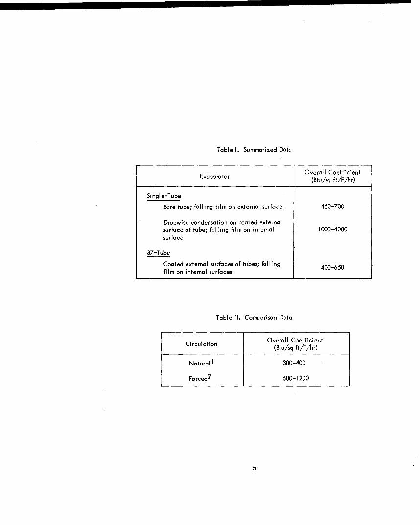
Table I. Summarized Data
Overall CoefficientEvaporator (Btu/sq ft/F/hr)
Single-Tube
Bare tube; falling film on external surface 450-700
Dropwise condensation on coated externalsurface of tube; falling film on internal 1000-4000surface
37-Tube
Coated external surfaces of tubes; falling 400-650film on internal surfaces
Table II. Comparison Data
Overall CoefficientCi rculation (Btu/sq ft/F/hr)
Natural 1 300-400
Forced2 600-1200
5

DISCUSSION
The values for the coefficients for falling films on the internal surface anddropwise condensation on the coated external surface were 2.5 to 5.7 times theoverall coefficients obtained from the runs when the falling film was on the externalsurface of the tube.
Dropwise condensation was observed over the entire surface coated with thepolytetrafluoroethylene polymer when the heating steam was condensing on it. Theaction of condensation did not wash away the coating.
The data in Figure 10 shows a drop in heat-transfer coefficient with increasinglevels of flooding in the 37-tube evaporator. This reflects the loss of surface areaavailable for a thin film. The difference is not great and indicates that littleadvantage was being gained because of the apparent difficulty of maintaining afalling film on longer tube surfaces. It is suggested that very thin, wiped films aremore advantageous and result in greater overall heat-transfer coefficients.
CONCLUSIONS
Dropwise condensation on a surface coated with a polytetrafluoroethylenepolymer improves heat-transfer coefficients sufficiently to make this method apossibility for future design criteria. The coating was very effective in inducingdropwise condensation.
There is an advantage in water-film evaporation, but the difficulty ofmaintaining a falling film on long, vertical tubes suggests that some other methodof obtaining thin films should be investigated.
REFERENCES
1. Badger, W. L., and W. L. McCabe. Elements of Chemical Engineering.McGraw-Hill, New York and London, 1956.
2. Hyatt, D. L., and J. A. Eibling. Methods of Improving Heat Transfer inEvaporators of Small Thermocompression Sea-Water Stills. Paper presented at theASME-AICHE Heat-Transfer Symposium at Northwestern University,18-21 August 1958.
3. Keenan, J. H., and F. G. Keyes. Thermodynamic Properties of Steam. JohnWiley and Sons, New York, 1936.
6

Figure 1. The single-tube evaporator, at its maximum length, with film fallingon external surface.
7

Figure 2. The single-tube evaporator, at its maximum length, with film falling
on internal surface.
8

platelat
conden sate
interna surface
9

~~~~~~~condensatino exenlsrae.
dit0lt

Figure 5. Apparatus for controlling thickness of film falling on externalsurface of tube.
11

Figure 6. The 37-tube evaporator, diesel engine, and compressor.
12

B0o
70D0
4.5 feetLL
7.3 feet
600J!
0
500 V
680 feet
4000 10 20
Feed Flow (gph)
Figure 7. Results of first test series with bare tube and falling film on externalsurface of tube, showing effect of feed flow and tube length onoverall heat-transfer coefficient.
13

4000
4:2. fe
6t .5
G)
1 000
00 23
Fccd Flow (gph)
Figure 8. Results of tests on dropwise condensation on polytetrafluoroethylene-polymer-coated external surface, showing the effect of feed flow andtube length on the overall heat-transfer coefficient.
14
2500
'. 2000
r 0
15000
So
0
10 5 01 02
Fiur 6.5-utfooesso cnenaio n ae tbeo in tuhe
5005

650
600Drp
'
C,
'~500
400
Water Level (feet)
Figure 10. Results of dropwise condensation on 37-tube evaporator,showing effect of partially filled tubes and three differentcompressor speeds on the overall heat-transfer coefficient.
16

DISTRIBUTION LIST
SNDLCode
Chief, Bureau of Yards and Docks (Code 70)
23A Naval Forces Commanders (Taiwan Only)
39B Construction Battalions
39D Mobile Construction Battalions
39E Amphibious Construction Battalions
39F Construction Battal'ion Base Units
A2A Chief of Naval Research - Only
A3 Chief of Naval Operation (OP-07, OP-04)
A5 Bureaus
B3 Colleges
E4 Laboratory ONR (Washington, D. C. only)
E5 Research Office ONR (Pasadena only)
E16 Training Device Center
F9 Station - CNO (Boston; Key West; San Juan; Long Beach; Son Diego; Treasure Island; andRodman, C. Z. only)
F17 Communication Station (San Juan; San Francisco; Pearl Harbor; Adak, Alaska; and Guam only)
F41 Security Station
F42 Radio Station (Oso and Cheltanham only)
F48 Security Group Activities (Winter Harbor only)
H3 Hospital (Chelsea; St. Albans, Portsmouth, Va; Beaufort; Great Lakes; San Diego; Oakland;and Camp Pendleton only)
H6 Medical Center
JI Administration Command and Unit - BuPers (Great Lakes and San Diego only)
J3 U. S. Fleet Anti-Air Warfare Training Center (Virginia Beach only)
J4 Amphibious Bases
J19 Receiving Station (Brooklyn only)
J34 Station - BuPers (Washington, D. C. only)
J37 Training Center (Bainbridge only)
J46 Personnel Center
J48 Construction Training Unit
J60 School Academy
J65 School CEC Officers
J84 School Postgraduate
J90 School Supply Corps
J95 School War College
J99 Communication Training Center
LI Shipyards
17

Distribution List (Cont'd)
SNDLCode
L7 Laboratory - BuShips (New London; Panama City; Carderock; and Annapolis only)
L26 Naval Facilities - BuShips (Antigua; Turks Island; Barbados; San Salvador; and Eleuthera only)
L30 Submarine Base (Groton, Conn. only)
L32 Naval Support Activities (London & Naples only)
L42 Fleet Activities - BuShips
M27 Supply Center
M28 Supply Depot (Except Guantanamo Bay; Subic Bay; and Yokosuka)
M61 Aviation Supply Office
Ni BuDocks Director, Overseas Division
N2 Public Works Offices
N5 Construction Battalion Center
N6 Construction Officer-in-Charge
N7 Construction Resident-Officer-in-Charge
N9 Public Works Center
N14 Housing Activity
R9 Recruit Depots
RIO Supply Installations (Albany and Barstow only)
R20 Marine Corps Schools, Quantico
R64 Marine Corps Base
R66 Marine Corps Comp Detachment (Tengan only)
W1AI Air Station
W1A2 Air Station
WIB Air Station Auxiliary
WIC Air Facility (Phoenix; Monterey; Oppoma; Naha; and Naples only)
WiE Marine Corps Air Station (Except Quantico)
W1H Station - BuWeps (Except Rota)
Deputy Chief of Staff, Research and Development, Headquarters, U. S. Marine Corps, Washington, D. C.
President, Marine Corps Equipment Board, Marine Corps School, Quantico, Va.
Chief of Staff, U. S. Army, Chief of Research and Development, Department of the Army,Washington, D. C.
Office of the Chief of Engineers, Assistant Chief of Engineering for Civil Works, Department ofthe Army, Washington, D. C.
Chief of Engineers, Deportment of the Army, Attn: Engineering R & D Division, Washington, D. C.
Chief of Engineers, Department of the Army, Attn: ENGCW-OE, Washington, D. C.
Library of Congress, Washington, D. C.
18

Distribution List (Cont'd)
Director, U. S. Army Engineer Research and Development Laboratories, Attn: Information Resources Branch,Fort Belvoir, Va.
Headquarters, Wright Air Development Division, (WWAD-Library), Wright-Patterson Air Force Base, Ohio
Headquarters, U. S. Air Force, Directorate of Civil Engineering, Attn: AFOCE-ES, Washington, D. C.
Commanding Officer, U. S. Naval Construction Battalion Center, Port Hueneme, Calif., Attn: MaterielDept., Code 140
Deputy Chief of Staff, Development, Director of Research and Development, Department of the Air Force,Washington, D. C.
Director, National Bureau of Standards, Department of Commerce, Connecticut Avenue, Washington, D. C.
Office of the Director, U S. Coast and Geodetic Survey, Washington, D. C.
Armed Services Technical Information Agency, Arlington Hall Station, Arlington, Va.
Director of Defense Research and Engineering, Department of Defense, Washington, D. C.
Director, Division of Plans and Policies, Headquarters, U. S. Marine Corps, Washington, D. C.
Director, Bureau of Reclamation, Washington, D. C.
Commanding Officer, U. S. Navy Yards and Docks Supply Office, U. S. Naval Construction Battalion Center,Port Hueneme, Calif.
Facilities Officer (Code 108), Office of Naval Research, Washington, D. C.
Federal Aviation Agency, Office of Management Services, Administrative Services Division, Washington, D. C.,Attn: Library Branch
Commandant Industrial College of the Armed Forces, Washington, D. C.
Commandant, U. S. Armed Forces Staff College, U. S. Naval Base, Norfolk, Va.
Chief, Bureau of Ships, Attn: Chief of Research and Development Division, Navy Department, Washington, D. C.
Officer in Charge, U. S. Navy Unit, Rensselaer Polytechnic Institute, Troy, N. Y.
Officer in Charge, U. S. Naval Supply Research and Development Facility, Naval Supply Center, Attn: Library,Bayonne, N. J.
Chief, Bureau of Naval Weapons, Attn: Research Division, Navy Department, Washington, D. C.
Commander, Pacific Missile Range, Attn: Technical Director, Point, Mugu, Calif.
Officer in Charge, U. S. Naval Supply Research and Development Facility, Naval Supply Center, Bayonne, N.J.
Commander, Norfolk Naval Shipyard, Attn: Metallurgical Laboratory, Portsmouth, Va.
Commander, Norfolk Naval Shipyard, Attn: Chemical Laboratory, Portsmouth, Va.
Commander, U. S. Naval Shipyard, Attn: Rubber Laboratory, Mare Island, Vallejo, Calif.
Commander, U. S. I-aval Shipyard, Attn: Materials and Chemical Laboratory, Boston
Commander, U. S. Naval Shipyard, Attn: Material Laboratory, Brooklyn, N. Y.
Office of Naval Research, Branch Office, Navy No. 100, Box 39, FPO, New York
Commandinn Officer, U. S. Naval Unit, U. S. Army Chemical Corps School, Fort McClellan, Ala.
U.S. Naval Research Laboratory, Chemistry Division, Washington, D. C.-
Deputy Chief of Staff, Research & Development Headquarters, U. S. Marine Corps, Washington, D.C.
Paint Laboratory, U. S. Engineers Office, Clock Tower Building, Rock Island, Ill.
U. S. Army Material Command, Washington, D. C.
19

0
A 0 .8 Distribution List (Cont'd)r L)B.0-u
U.S. Army Corps of Engineers, Office of the District Engineer, St. Paul District, 1217 U.S.P.O. and CustomsE_ House, St. Paul, Minn.
-o aAir Force Cambridge Research Center, Hanscom Field, Bedford, Mass.
Directorate of Research, Air Force Special Weapons Center, Kirtland Air Force Base, N.M.
Sandia Corporation, Attn: Classified Document Division, Box 5800, Albuquerque, N. M.
0 0 Chief, Physical Research Branch, Research Division, U. S. Department of Commerce, Bureau of Public Roads,- .? -Z:t Washington, D. C.
7, .20- 0 a0'0 Director, Engineering Research Institute, University of Michigan, Ann Arbor, Mich.
o W U u Library, Engineering Department, University of California, 40 5 Hilgard Avenue, Los Angeles0~ zR o Z o
0 '- Library, Battelle Institute, Columbus, Ohioa Library, University of Southern California, University Park, Los Angeles
u c Ia - Director, The Technological Institution, Northwestern University, Eanston, Ill."6 o - o 2o c Library, Institute of Technology, University of Minnesota, Minneapolis, Minn.
-- u o Library, California Institute of Technology, Pasadena, Calif.
a o c.. c a Wv -z d)
a--
z 3 'a
0 , -
- -- , ' - '----- a ----
.2 -S c -
u u or' Z
o
-o 0><
o
22O
u 4

00 000
-0 0
L E -j 0- ">'0 O In w
-- P -_ _
• '.- o- 8 .o o I .-
4) 0c-q .-
w z 0 r ,
00 r E t I zz
vo z a-o o 00
2 1'-
FT X, : 0 - .. w= - 0
'.'~2 -0-"' a. x -
- - - L -' - -- - - - - -. -- -.__ - - --
8 o
' 8. '68
,-.-r-T:-
, . =_ ==.o.
0BCZE U= -~Z~0~
-aC C
.z _00u - L0
zo W
00 Z . 2 ZZ LL
2 L 0 Z~U
00
0C E. 0,2
S0•C 0I X -
Mt 0 'a2 .r '0±
Ugu - W<O
UU 0100
U~.' - .,,., .'- 6 ,
- "-
.~wu> 0 Iu -Zo x~