Embed Size (px)
Citation preview

- T qL5 i
., pr i i i
",• /t
,///
MATERIALS - 4340 /TEEL - STRESS CORROSION AND
EFFECTS OF BANDING - LITERATURE
SURVEY
ART II EFFECTS OF BANDING
DDC4
Published and distributed under Contra No.AF33(657)-11214, Air Force Materials La rato.y,Aeronautical Systems Division, Air Force ystemsCommand, Wright-Patterson Air Force Base, hio.
GENERAL OYNAMICE I FORT WORTH

QEINERAL DYNAMICS FORT WORTH
TE.3T NO. 30-2007 REPORT FGT 29,7 Pt.Il
MODEL B-58 DATE 23 March 19624
TITLE
MATERIALS - 4340 STEEL - STRESS CORROSION AND EFFECT.- OF BANDING -
LITERATURE •URVEY
PART II EFFECTS OF BANDING
SUBMITTED UNDER
Contract Number - JAF33(6OO)-41891 -_ .
PREPARED BY: - GROUP: MetallurgicalP.I. •ena S Engineering Test Laboratories
REFERENCE: _ _ _ _ _
CHECKED BY*jL6 J' - APPROVED BY: ___ __R. L. 7ones F. C. NordAcist
NO. OF PAGES 44
NO. OF DIAGRAMS___
REVISIONS
NO. DATE my CHANGE PAGES AFFECTED-m• -
___ _ _ _ _ _ _ I _ _ _ _ _ _ _ __,_ _ _ _ _ _ __,

,PAGE I
REPORT NO_ ______ ___
lNIERAL DYNAMICS i PORT WORTH MODELT----7-"DATE •- •3-64
ACKNOWLEDGMENTS
The author would like to express his appreciation to
the employees of the Division Research Library who were so
helpful in obtaining literature which was not available in
the library. Many of the articles were in obscure Journals
and in periodicals which were published befcre our library
came into existence which made the 'ob difficult.
Thanks are also due to Messrs. R. .. Jones, j. F.
Hildebrand, and F. C. Nordquist for their aid in proofreading
and helping to arrange the information. In reviewing
voluminous amounts of information, it is quite easy to begin
to assume that principles reviewed many times are well known.
Their pointing out areas that required clarification was
very helpful In assuring the readability of this report to
the average metallurgist.
I
4
UTiLItY lllOOTSH$FV OIMPAUIhdg--I •
PAG 1i 1
111111111)POT NOGENERAL ovNAMiCU I Porr wopir'H MO:E
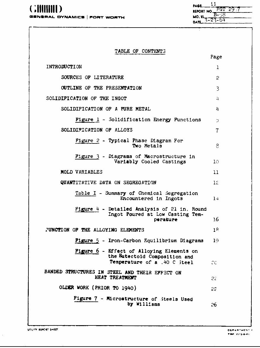
TABLE OF CONTENTS
Page
INTRODJCTI ON 1
SOURCES OF LITERATURE 2
COTLINE OF THE PRESENTATION 3
SOLIDIFICATION OF THE INGOT
SOLIDIFICATION OF A PURE METAL
Figure 1 - Solidification Energy Functions
SOLIDIFICATION OF ALLOYS 7
Figure 2 - Typical Phase Diagram ForTwo Metals
Figure 3 - Diagrams of Macrostructure inVariably Cooled Castings 10
MOLD VARIABLES 11
QUANTITATIVE DATA ON SEGREGATION 12
Table I - Summary of Chemical SegregationEncountered in Ingots 14
Figure 4 - Detailed Analysis of 21 in. RoundIngot Poured at Low Casting Tem-
perature 16
"2UNCTION OF THE ALLOYING ELEMENTS
Figure 5 - Iron-Carbon Equilibrium Diagrams 19
Figure 6 - Effect of Alloying Elements onthe Eutectoid Composition andTemperature of a .40 C 3reel
BANDED STRUCTURES IN STEEL AND THEIR EFFECT ON
HEAT TREATMENT 2
OLtU WORK (PRIOR TO 1940) 2
Figure 7 - Microstructure of •teels Usedby Williams 26
UTILITY 11" $041A.M( T w .... 1, ,9,0,
PAGN i(,111111111) REO" POT 2REPORT' No, FGT 2957MUNURAL DYNAMICS I ORT WosWr B z
DA1 3-23
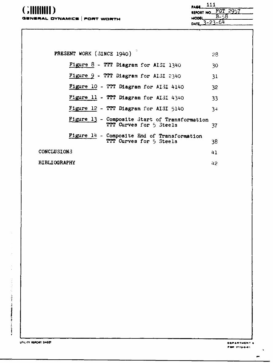
PRESENT WORK (SINCE 1940) 28
Figure 8 - TTT Diagram for AISI 1340 30
Figure 9 - TTT Diagram for AISI 2340 31
Figure 10 - TTT Diagram for AISI 4140 32
Figure 11 - TTT Diagram for AISI 4340 33
Figure 12 - TTT Diagram for AISI 5140 34
Figure 13 - Composite Start of TransformationTTT Curves for 5 Steels 37
Figure 14 - Composite End of TransformationTTT Curves for 5 Steels 38
CONCLUSIONS 41
BIBLIOGRAPHY 42
I
UTILITY l1o1 SHUTo
pop
PAGE If)ROT HO FGT 2957
MNNERAL AIYII P T WC2Mrr M00e B-N 8DATJ 3-23-64
LITERATURE SURVEY ON BANDING IN STEEL
INTRODUCT ION
During the course of investigations of several tests and
sprvice failures in components of the B-58 landing gear, It
was noted that the structure of the steel was banded. Banding
manifests itself as groups of light and dark etching grains
adjacent to each other and strung out In the direction of
rolling or forging flow, in a polished and etched metallo-
graphic specimen. These groups or rows of similar grain have
the appearance of bands; hence the name banding. The presence
of oandlng in a failed part was Investigated as a cause of
falur*e, but usually it was not severe, and, In most cases, the
dire•tlon of loading was parallel to the direction of banding.
Limited literature searches, made at these times, produced very
few papers on the subject. In the only paper that contained
strength data, the only effect of banding was a reduction of
elongation properties of normalized SAE 4340 steel in the
transverse dire *•, •-* , (IT) The yield and ultimate strengths
were oopaqrable. Mtcrohlrdness traverses made across the
VILF?' iotln S(m if (Otpoapm9'.
-,1 11111)"1mI REPORT N FGT 29,7
GENEPRAL IOVNAMICs I onoRT wORTmD 3-23-64
banded area of failed materials showed Insignificant differences
in hardness and strengths where tensile tests were conductei.
In all cases it was impossible to attribute any portion of the
cause of failure to banding. Some element of doubt did exist,
however, and the need for knowledge of the effect of banding
in steel became apparent.
In discussions with vendors and other agencies, it
appeared that banding was much like the weather. Everyone
knew it existed, but no one did anything about it. When *,he
landing gear materials evaluation testing was undertaken, It
was decided to conduct a comprehensive literature survey on
banding, concurrent with the one on stress corrosion.
Sources of Literature
The ASM Rev~ew of Metal Literature was the most lucrative
source of information on banding. Bibliographies from initially
reviewed articles provided additional references. The Ohemical
Abstracts. Physical Abstracts and Industrial Arts Index also
provided many references. All were reviewed for the past f!ve
years under each litting that could be remotely connected with
the subject. The bibliographies of these articles indicated
that this provided a good cross section of the literature tack
to 1940. In addition to work done in this country, it was
-iw" •,t , i. I., $, • O&l Iqlr e

- (,I I I III ) ,,POT O.l- GENERAL OVNAMICI POWrT vWo"rOB
-OATh 3.-23-6:.
also found that work had been done -An England, France, Switzer-
land, and Fassla.
Outline of the Presentation
It is generally agreed that banding Is the result of
heterogeneities that occurred durin3 solidification in casting
the original Ingot of steel. The Ingot is stripped from the
mold, then transferred to "soaking pits" where It Is held for
a period of time at 2000 - 2300 F to permit diffusion of the
alloying elements to lean areas, or homogeniz&tion to occur.
The Ingot Is then cropped (cut off) to remove areas where
shrinkage has produced voids and the Ingot Is hot; bloored Into
a forging or rolling slab. In the subsequent for-ing or rolling
operation any remining heterogeneity is elongated In the
direction of working and results In banding. During heat treat-
ment, any difference in alloy content causes a difference In
response and a resulting difference in structure. This lcotcally
arranges the discussion of banding into: (1) Solidification of
the ingot, (2) Nnction of the alloying elements, and (3) Banded
structures and their effect on heat treatment.
F Siee
CKENSUAL DVYNARACS PROOT WORP"h
SOLIDIFICATION OF THE INGOT
(1)Form anJ mallace discussed the solidtifcation of metals
starting with the freezing of a pur-e metal.
A superleated pure metal allowed to cool slowly "n the
container In which it was melted will gradually and evenly
lose temperature until the freezing (solitlltcation) point is
reached. At this point, Ideally, the latent neat of fasion
will hold the temperature constant as freezing takes plaze.
The temperature will irop after freezing with the slope of
the time-temperature curve remaining Censtant If no phase
change Is encountered. The process of freezing Is one of
nucieation and growth. The atoms within a liquid near tne
freezing point tend tc cluster together or form nuclei. The
change In free energy A P is represented ty:
AF = a 3 - Apv + 6&2 • AF31
where a Is the edge length of the cubical e-bryo,&Pv is the
free energy change evolved from passing from a liquid to sol'.
volume, an~sl Is the Interfacial free energy between the
two phlses. As shown by upper diagrar. In Pigure 1, these
opposing runctions result In an Increaso o!' free energy to a
certain level beyond which It decreoses. The decreaw' In free
erlg beyond this point causes the reaction to occur and growth

J" REPORT NOFjGT 291)1C3ENERAkL DYNAFM4ICU POORTr wO:RT-rH DAE -58-4_
7'4A
'46
Lra
7-m >7,-> 7- r
/, 1,I4 'e FAfV ( I'e
UTIOTYREPORT SHEOf1. - N
******** ~PAGE-.. 6IREPORT No FGT 2927
cUENERAL DYNAMICS , PO0T WORPTH MOD L._ Bi--i IDA1_ 3-23-64
of the grain results. This actually causes supercoolinv of
the liquid to a temperature below that at which it melted.
As shown in the lower diagram o2 Figure 1, Lhe amount of super-
cooling makes it possIble for smaller stable nuclei to exist.
This would result in a finer grain size.
The conditions of homogeneous nucleation of a pure metal
ar'e expanded to conditions of heterogenous nucleation of a pure
metal as occurs in casting. When the superheated metal is poured
into a cool mold, the temperature of the liquid adjacent to the
wail reaches that of nucleation quickly and the fine grained
chill layer forms quickly. The grains gradually become larger
as the walls of the mold are heated to equilibrium with the
melt and tne solid-liquid interface approaches the melting
point. The heat being removed from the ingot, through the mold
walls and the solid layerdoesnot produce sufficient supercooling
to permit further nucleation at this point so the already
solidified grains grow inward. This results in a columnar
zone in the ingot. Depending on mold configuration and tem-
perature gradient, the temperature of the liquid will again be
supercooled to a point where nucleation can occur and the re-
maining liquid will again nucleate and grow equiaxed grains.
The proportions of chilled, columnar, and equiaxed zones will
vary from metal to metal.
UTIt ITY WPOIT SHEES O&PARTMCNIT
FWIP 1072-t-0 I
PAGE.
(IIIREPORT NO FGT257CUUNNRAL OV.6JAM4UCS PEORI VCPR WORTH_ý
I,
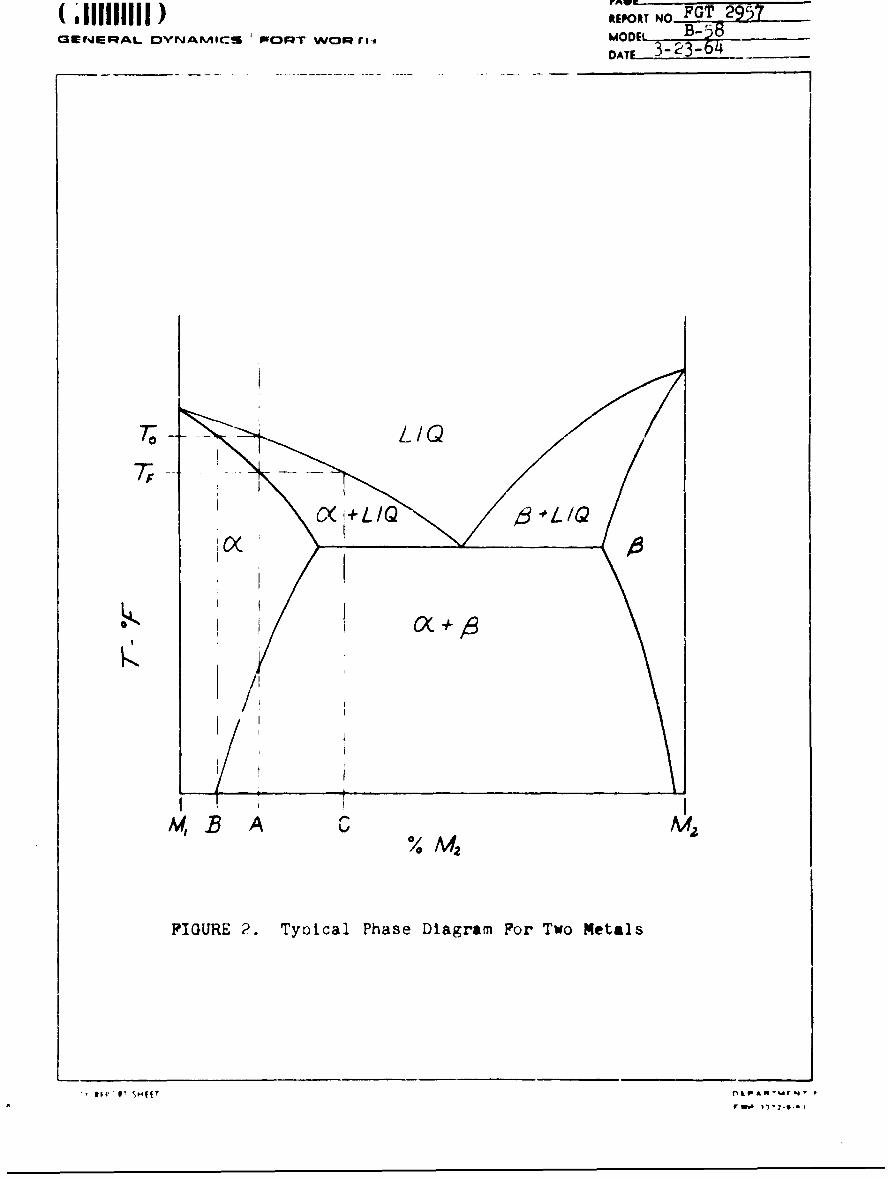
The solidification of alloys cauises the situation to
become complicated because the melting point does not remain
constant. In the case of a solid solution freezing from a
homogeneous melt of composition A, the freezing temperature(3)
of the initial nuclei would be "To" as shown in Figure 2.
The composition of the nuclei is B. As the nuclei grows and
the temperature is lowered the composition of the melt becomes
enriched and the composition at the solid-liquid interface
becomes enriched. The last of the melt solidifies at tempera-
ture Tf and the composition of this portion is C. If the melt
solidified evenly in a single crystal, the composition at the
center would be B and that of the outer surface would be C.
This Is known as coring. In casting this alloy in a mold, the
chill layer would freeze too rapidly to show any of this effect.
As the solidification rate decreased, there would be sufficient
time for this coring to occur.
The structure of the columnar zone of an alloy is not
perfectly columnar. The grains usually develop as dendrites
whioh can be described as crystals having tree-like patterns
composed of many branches projecting in all directions. These
dendrites are lean in alloy content and the areas between
them are rich. In addition, the concentration in the center
UTILITY REPORT SHEET l pIPAWT, JINT A
( ;111 ] ) ;=';or A o Td 2957.. .GENERAL DYNAMICS ! FWORT WOdntiv MODEL B--58
DATE T-23-64_
TF-,
TO( LIQ
/ '/10
M, B A C A4
FIGURE 2. Tyolcal Phase Diagram For Two Metals
- A ' "f'i r• 4'-- 0

PA09 9q .IPOST No. 10T 2957
GENERAL OYNAMICSI momrr Womr-m MODEL- 3-3-
DMý - 3-23-64
of the ingot is richer than the surfaces. The enrichment of
the interdendritic areas is the result of coring during growth
of the dendrites and entrapment of the liquid that becomes
enriched as the coring develops. The natural solute enrichment
of remaining liquid causes the last area to freeze to be more
concentrated in that element. The interdendritic segregation
is termed microsegregation while the surface to center segrega-
tion is macrosegregation.
Another cause of macrosegregation is gravity or the "falling
crystallite" (2, 4) theory. The change in volum, on freezing
is a contraction for most metals. This increases the density
of the solidified nuclear crystals and they tend to sink to
the bottom of the mold. The natural rise of heat and heat loss
through the bottom of the mold add to this effect producing a
top to bottom segregation in addition to the surface to center.
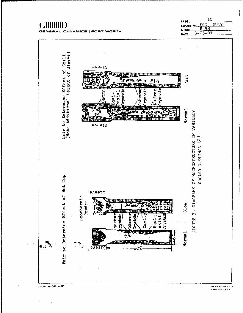
One paper(2) dealt with cooling rate and Its effect on
the resulting structure of a .35 carbon steel. The cooling
rate of six Inch diameter-30 inch long ingots was varied using
exothermic powder and chills in the sleeve or riser a* the top
of the ingot to decrease and increase cooling rate. As snown
in Figure 3, columnar zones of the slabbed ingots were increased
by slower cooling in each pair of ingots poured from a common
Ult,!Y IPWT SHIP OlPAYWMCm•, 0
VWO 1$0V•I-9-4 i
PAGE 10
J 11111111) REPORT NO FGT 2)csmrjoRA- oya~keas am-rwc~prrmMODEL B.-5
'->
..- ID
V~)
0-
04 c
~~14
00-
000 Z0
0 4 Z
iDAaaTS l
C)>0)
O~OZ
4E,E-0 0
4.()
C-q
o4.3
0 -4 .......-

PAO 1
(;iOIII NP o FrT 2957MUNUIRAL OVNAMIC3 I IROMI WORTH ,NDK_ • B-5
DATI_. 3-23-64
header. The equiaxed zone, or -one of larger equtaxed crystals,
was found at the bottom of the mold and increased in size with
slower cooling. The columnar zone of the slowest cooled ingot
was also thinner at the expense of equiaxed crystals indicating
fallen crystallites fornmed this region while the columnar
growth was taking place in the upper portion of the ingot. The
remaining portions, nuclear crystals, were equiaxed, but not
large grained, indicating that they all grew and solidified
under similar conditions, probably at the same time. The degree
and area of segregation were unmistakable.
Although porosity a+nd cavities do not directly affect
banding, they are a very real and closely related problem.
Note that the casting in Figure 3 that had the most homogeneous
structure also had the least porosity. This ingot could be
cropped at the sleeve and the remainder would be a porosity free
ingot ready for further processing. In this case the mold
design and pouring conditions produced a sound Ingot which had
minimum segregation. There are many variables that enter into
the design of an ingot mold; some help to minimize segregation
while others promote it. Ia order to produce a porosity free
casting, also free of a nloe or shrinkage cavity downward from
the top of the ingot, hot tops are used similar to the sleeve
UO LI' 2102r,,•u P - ot-mA"miit w. .
01Wy .la-e-.•
(11111111PA) 12
-IZoaT FGT 2957AkM B-5dM-NURAL DYNAMICS I POlV" Vwow, AO 33-
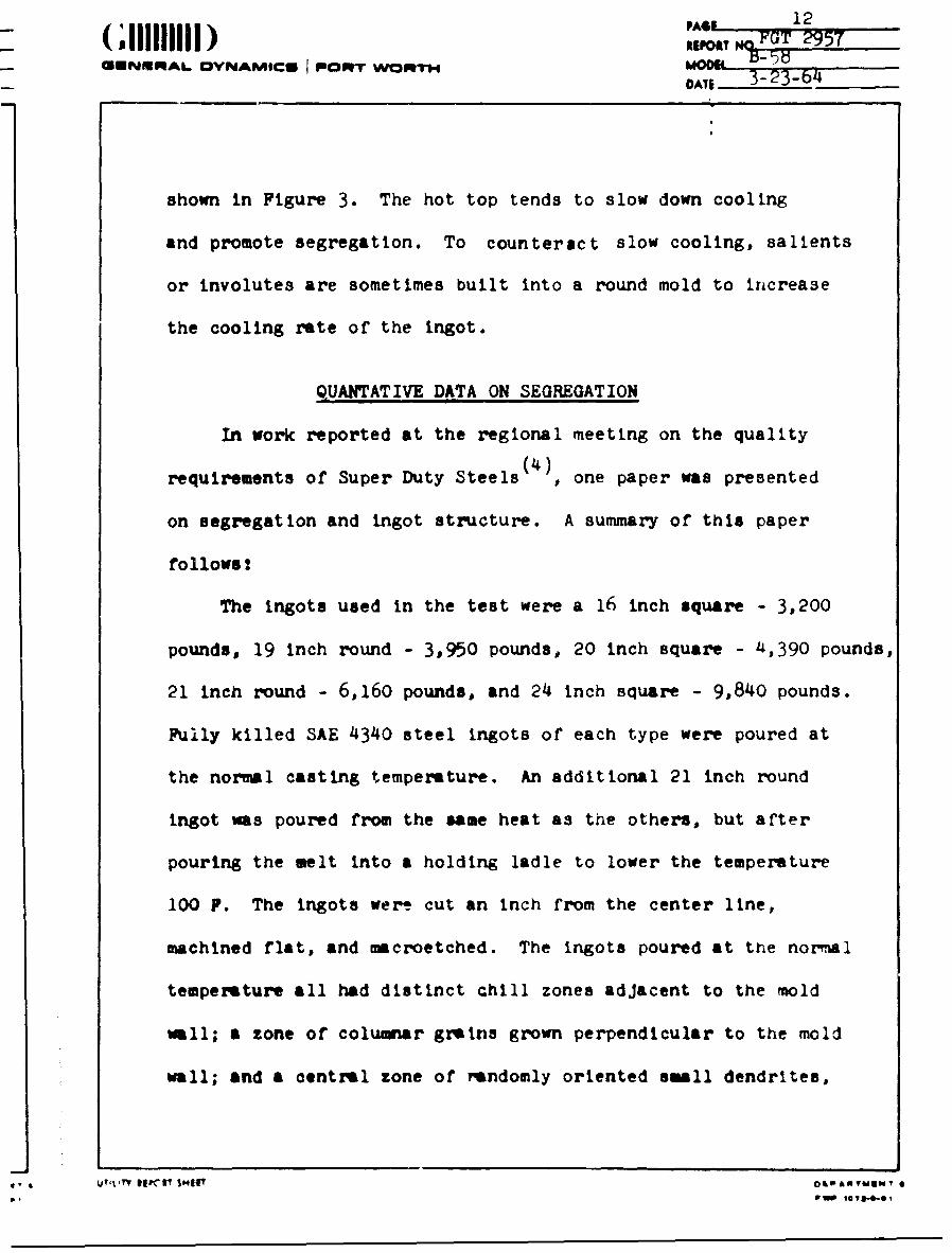
shown in Figure 3. The hot top tends to slow down cooling
and promote segregation. To counteract slow cooling, salients
or involutes are sometimes built into a round mold to increase
the cooling rate of the ingot.
QUANTATIVE DATA ON SEGREGATION
In work reported at the regional meeting on the quality(4)
requirements of Super Duty Steels , one paper was presented
on segregation and ingot structure. A summary of this paper
follows:
The ingots used in the test were a 16 inch square - 3,200
pounds, 19 inch round - 3,950 pounds, 20 inch square - 4,390 pounds,
21 Inch round - 6,160 pounds, and 24 inch square - 9,840 pounds.
Fully killed SAE 4340 steel ingots of each type were poured at
the normal casting temperature. An additional 21 inch round
ingot was poured from the same heat as the others, but after
pouring the melt into a holding ladle to lower the temperature
100 P. The ingots were cut an inch from the center line,
machined flat, and macroetched. The ingots poured at the normal
temperature all had distinct chill zones adjacent to the mold
wall; a zone of columnar grains grown perpendicular to the mold
wall; and a central zone of randomly oriented small dendrites,
.' . U 1 TL *Il'IT $1t4r o&-amvlba vw *
(,1111111 ,AC 13.R;OAT NO PTUUNURAL DYNAMICE I POMQT WORTH MOoE, B- 8
DATE 3-23-64
which were finer towards the center and bottom of the ingot.
There was some "herring bone structure" toward the top center
portion of the ingot. These are hot tears that occur in the
last portion to freeze and their length was related to the ingot
length-diameter ratio. These are of little consequence wnen
sufficient hot work was done on the Ingot to weld them, or
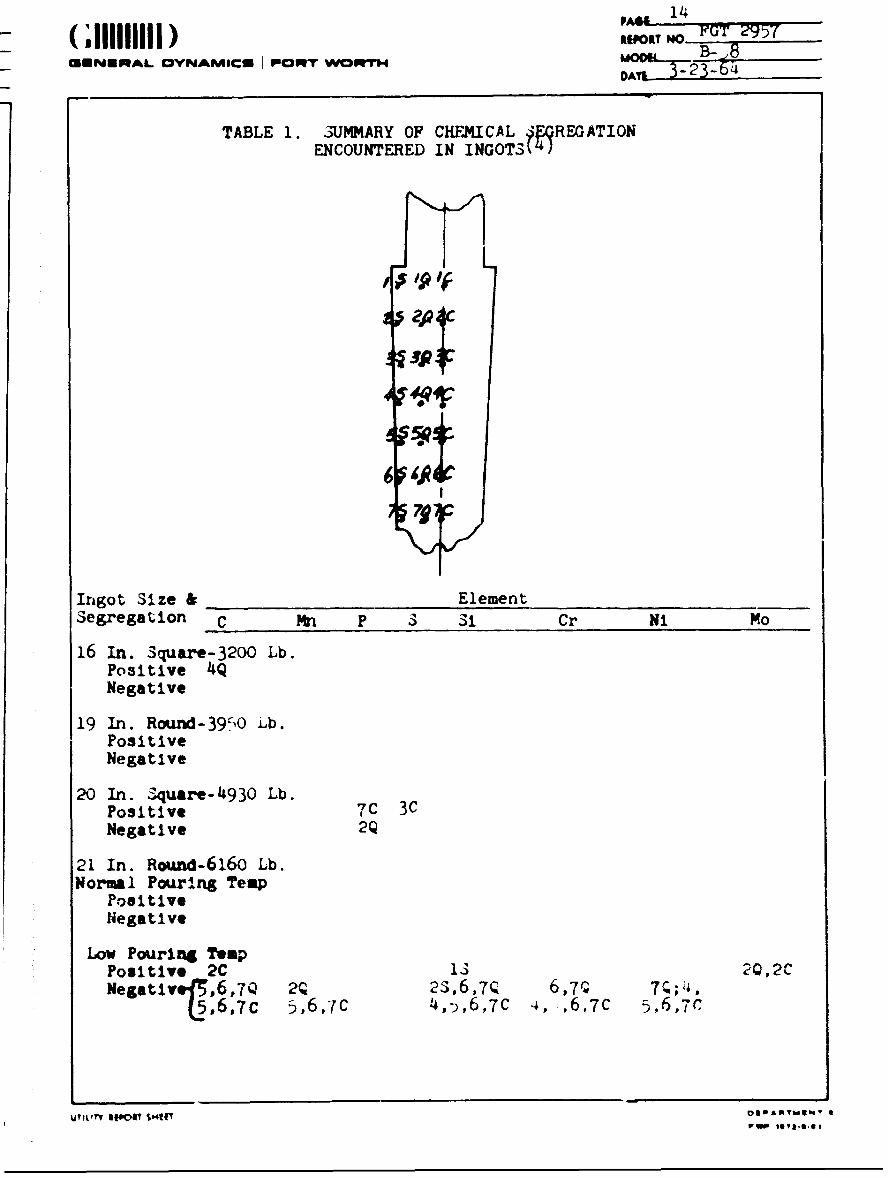
"heal" the porosity. Drillings were taken for chemical analyses
of the alloy and "tramp" elements at seven equal heights at the
surface, center, and quarter thickness of the ingot. A summary
of the results is shown In Table I. The presence of segregation
was determined by calculating an allowable error according to
ASTM standards. The minimum and maximum allowables were
determined by adding and subtracting the error from the average
of all tests made on each ingot. Contents greater than the
maximum were considered a positive segregation of the element
and les than the minimum, negative. There was some positive
carbon segregation indicated on the lb inch square ingot, but
this was barely above the maximum (.430>.429) and adjacent
analyses did not appear to indicate any trend. The evidence of
phosphorous and sulfur segregation in the 20 inch square Infot
was also very small and can be considered academic since the
contents were small (in the renge of .020% compared to .040%
maximum for aircraft quality SAE 43"0). The most significant
OjYIL"T " SIP r $&1L' oeaT.;iv. 0
Pa. 1372-0-01
A"14 M(,111111REPORT No r 29 57MmNEIRAL OYNAMICS I PIOlt WOWTH MOM B- 8
DAL 323t
TABLE 1. 3UMMARY OF CHFMICAL fflREGATIONENCOUNTERED IN INGOTSt)
ZIP
Ingot Size & ElementSegregation C Mn P 3 S1 Cr Ni Mo
16 In. Square-3200 Lb.Positive 4QNegative
19 In. Rourd-390 Lb.PositiveNegative
20 In. Square-4930 Lb.Positive 7C 3CNegative 2Q
21 In. Round-6160 Lb.Normal Pouring Temp
PositiveNegative
Low Pouring TmpPositive 2C 1S 2Q,2CNegatlve{ 6,7Q 2Q 23,6,7Q 6,7, Tr;!
"L6D, ,7C 5 ,6,7C 4,,,6,7C 4, ,6,7C 5,6,7C
UTILIrI *fqlT $14"O# OAUYm3hV *
PAGE 1
1,11 )REPORT N FGT 97GUNEIUAL. OCVNAMICU I upiwr #dVrT m B-i.8OT 3- 23-64
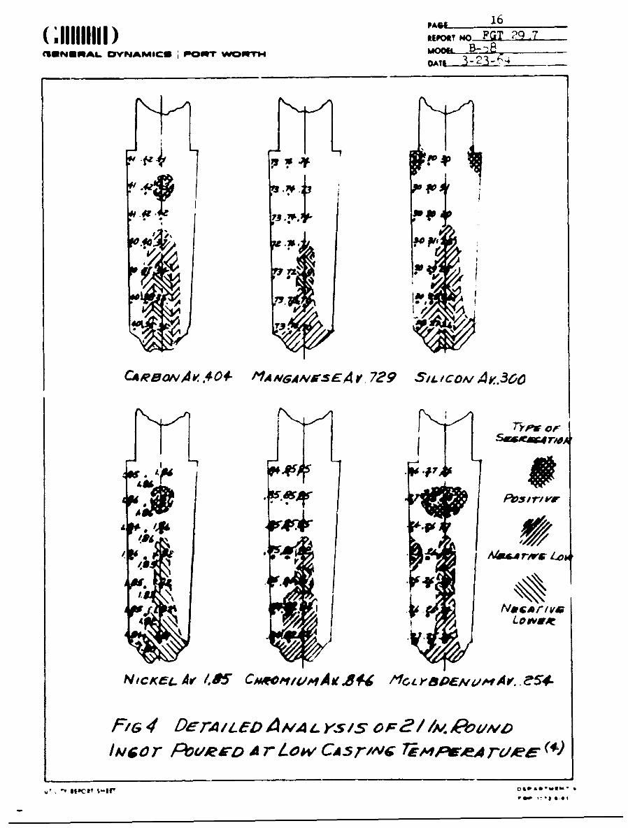
segl egation occurred in the 21 Inch round ingot which was cast
cold. A detailed analysis of this Ingot 13 shown in Figure 4.
Note that there is negative segregation in the middle bottom
for each element. Tnis was probably due to "falling crystallite"
phenomenon caused by the colder liquid tending to form both
more and larger stable nuclei as explained previously. Thi.
enriched the remaining liquid, and the carbon, nickel, and
molybdenum segregated positively In the last area of the ingot
to freeze. This area had a herring bone appearance in the
macrostructure. Hot tearing relieved the shrinkage stress
formed during solidification, and directional thermal con.raction
caused the herring bone pattern.
A further Investigation was made to determine the effect
of pouring temperature on carbon segregation in medium carbon,
low alloy, open hearth steels. These were 21 Inch round - 6,160
p•und ingots which were cropped, top and bottom, and then hot
sheared into forging blooms. The top and bottom blooms were
sampled and checked for carton content in the first -nd last
Ingot from each heat. ieventeen heats were poured cold, ten
heats poured at normal temperature, and seven heat3 poured
hotter than normal. The carbon contents varied from -7,) tc
.63% and alloys were of the lXI, l3XX, 3iXX, 4DXX, 4lXX, -,1XY,
46xx, '0UXX, 511X and 86XX families. The heats poured hot and
normal exhi.aited a .015 to .021% difference In carbon content
from top to bottom in both the first and last Ingots, while
writI
PAC&- 16
CIUNURAL OVNAMICU PNQMI WORTHmo p-p8
P
7P3
C,4Re aAA .4 04- 11AvA ,I rsEA V 729 SaaIoM AK..360
~ *47
44~
FIG 4 DeTA Ii-eO AMzALys Is oF 2//Mop& ovmo
IAl~ co POU1RED A r I- vw CA -5rNv 7,E"'~wA ru~e-V
IV **ot. &-IC
- 7
aE&NMElAL OYNAMICU PROFIT WORTH MODEL.-
the neats poured cold showed a .0 "C to .050% difference, This
was the only trend noted. -ýInce drillings were analyzed to
determine the composition, t-Ne carbon co;'tert variation mu.;t
bc considered a measure of tnc macroseg-regat 'on.
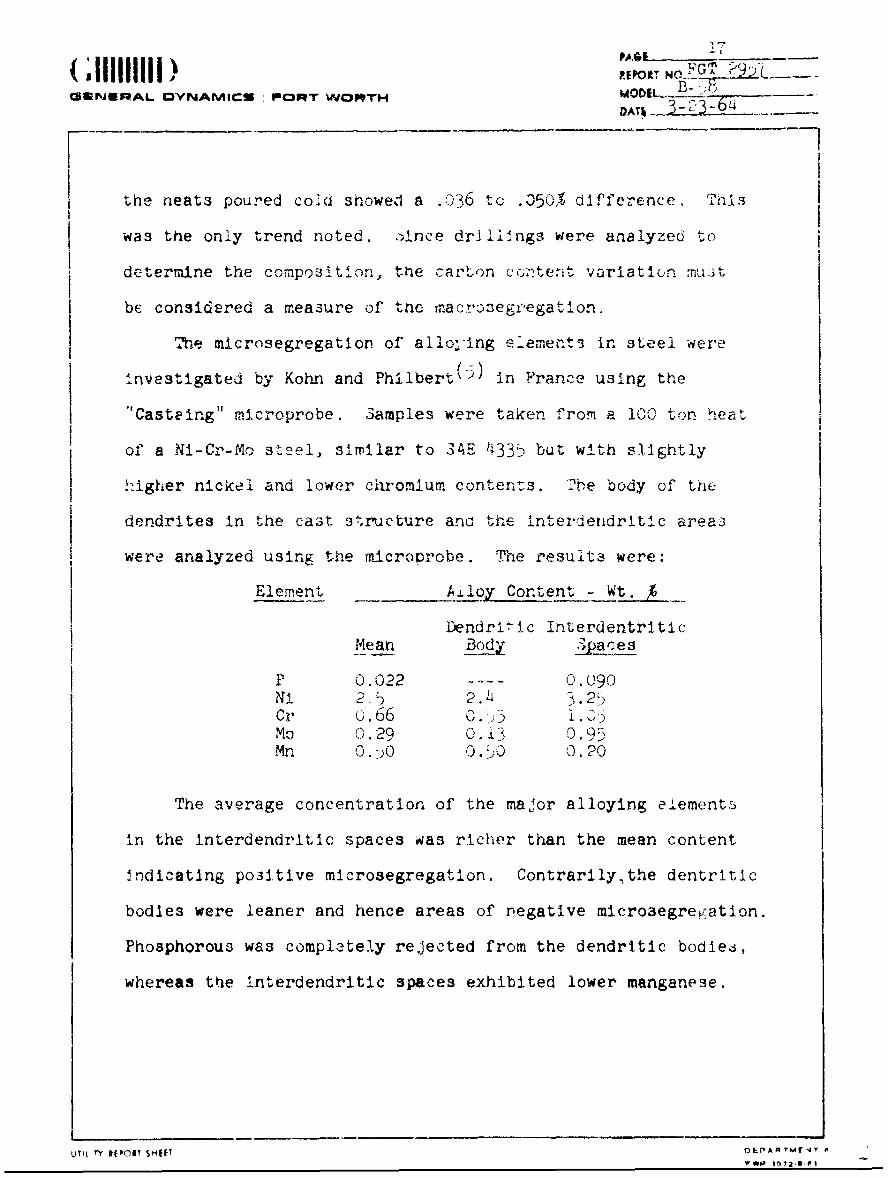
The microsegregation of alloIng ements in steel were
investigated by Kohn and Philbert(5) in France using the
"Casteing" microprobe. 3amples were taken from a 100' ton heat
of a Ni-Cr-Mo steel, similar to SAE 4335 but with slightly
higher nickel and lower chromium contents. rbe body of the
dendrites in the cast structure and the interdendritlc areas
were analyzed using the microrobe. The fesults were:
Element Ailoy Content- W.
Dendrl•ic InterdentriticMean Body STýa e s
P 0. 022 .O090Ni 25 2.41 3.2,Cr .660.Mo 0. 29 0. 13 O, 95M 0. 50 0.50 0.20
The average concentration of the major alloying elements
in the Interdendritic spaces was richer than the mean content
Indicating po3Itive microsegregation. Contrarily.the dentritic
bodies were leaner and hence areas of negative microsegregation.
Phosphorous was completely rejected from the dendritic bodie6,
whereas the interdendritic spaces exhibited lower manganese.
uTq rYI REV(INT SHEET O&.PARTkt4'T A
; iPA0 18;i11111111 No ,,>, 295zGUNSGRAL OAM,3CS i P.OtT WORTH M0D. 1 .
FUNCTION OF THE ALLOYING ELEMENTS
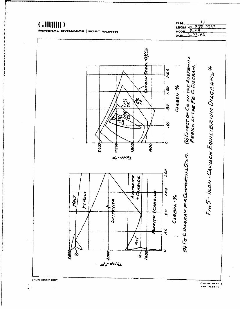
Carbon is the major alloying element In steel. ThŽ heat
treatment of steel is based on the greater solubility of carbon
in face-centered cubic austenite or gamma iron, ond the decreased
solubility in the body centered cubic ferrite or alpha iron.(6)
As shown in Figure 5a , the temperature at which tnis occurs
varies with carbon content.
Change3 in the shape of the Iron-caroon diagram affect,.
by the addition of elements are used to explain the characteristics
of various steels. For example, chromium shrinks the austenite
loop, and shifts the temperature and composition of the eutectoid
as shown by Figure 5b.
The effect of various elements on a .40% carbon steel
have been determined and are shown by Figure 6. Manganese and
nickel depress the transition temperature, A3, at which the trans-
formation from ferrite to austenite is complete, while the other
elements raise it.
Phosphorous and sulfur, considered tramp elements in most
ca3es, are present in the ores. During .he refining processes,
they are minimized, but what does remain has a profound effect
on steel. Usually controlled to .05% maximum, ,hosphorous(8)
has a low solubility in both alpha and gamma iron and tends to
segregate. While it does not form carbides, it has a great
effect on the hardenability of the steel. Sulfur, -enerally
UTILI i REPORT SHIET O&PD ,TMIENT 010W I'a-9l-6
REPORT No- FGT 29'57CUN&RAkL OYNAkmico pmDI - WFOMT .W0Th
'k4'
~~14
kr
UTLT IMTSHEOLPR EN
.3w

( ;~iiii )PAGE 20REPORT NO ?U' 2 ..'
CWENERAL OVNAMICUo I POpqT WORTH. B-58iDAYL. 3-23-64
0400 ~
/600
aZ
01 7)
Ow A I0 C 5rO/7)
UTILIrY ESPOT SHIP IV~uw
PAGE 21(ll I) REPORT No FGGENERAL. OY!JA4I,41E~q•l POilllrY W(•?Y ,Mpl- iODl•]-5
DATE 3-23-64
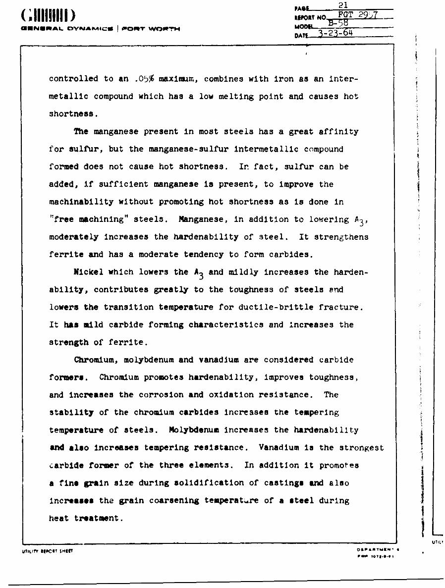
controlled to an .05% maximum, combines with iron as an inter-
metallic compound which has a low melting point and causes hot
shortness.
The manganese present in most steels has a great affinity
for sulfur, but the manganese-sulfur intermetallic compound
formed does not cause hot shortness. In fact, sulfur can be
added, if sufficient manganese is present, to improve the
machinability without promoting hot shortness as is done in
"free machining" steels. Manganese, in addition to lowering A3 ,
moderately increases the hardenability of steel. It strengthens
ferrite and has a moderate tendency to form carbides.
Nickel which lowers the A3 and mildly increases the harden-
ability, contributes greatly to the toughness of steels and
lowers the transition temperature for ductile-brittle fracture.
It has mild carbide forming characteristics and increases the
strength of ferrite.
Chromium, molybdenum and vanadium are considered carbide
formers. Chromium promotes hardenability, improves toughness,
and increases the corrosion and oxidation resistance. The
stability of the chromium carbides increases the tempering
temperature of steels. Molybdenum increases the hardenability
and also increases tempering resistance. Vanadium is the strongest
carbide former of the three elements. In addition it promotes
a fine grain size during solidification of castings and also
increases the grain coarsening temperatare of a steel during
heat treatment. i- UTILI
UTILIty ry I ' $OIP&MTMN' SPrP I07l.-e-9I
(;111111111)"oRr" ):,)T 7
astUNEtAi. IDvYNAMICs I POwT WORT"4
CAm- 3 -23-
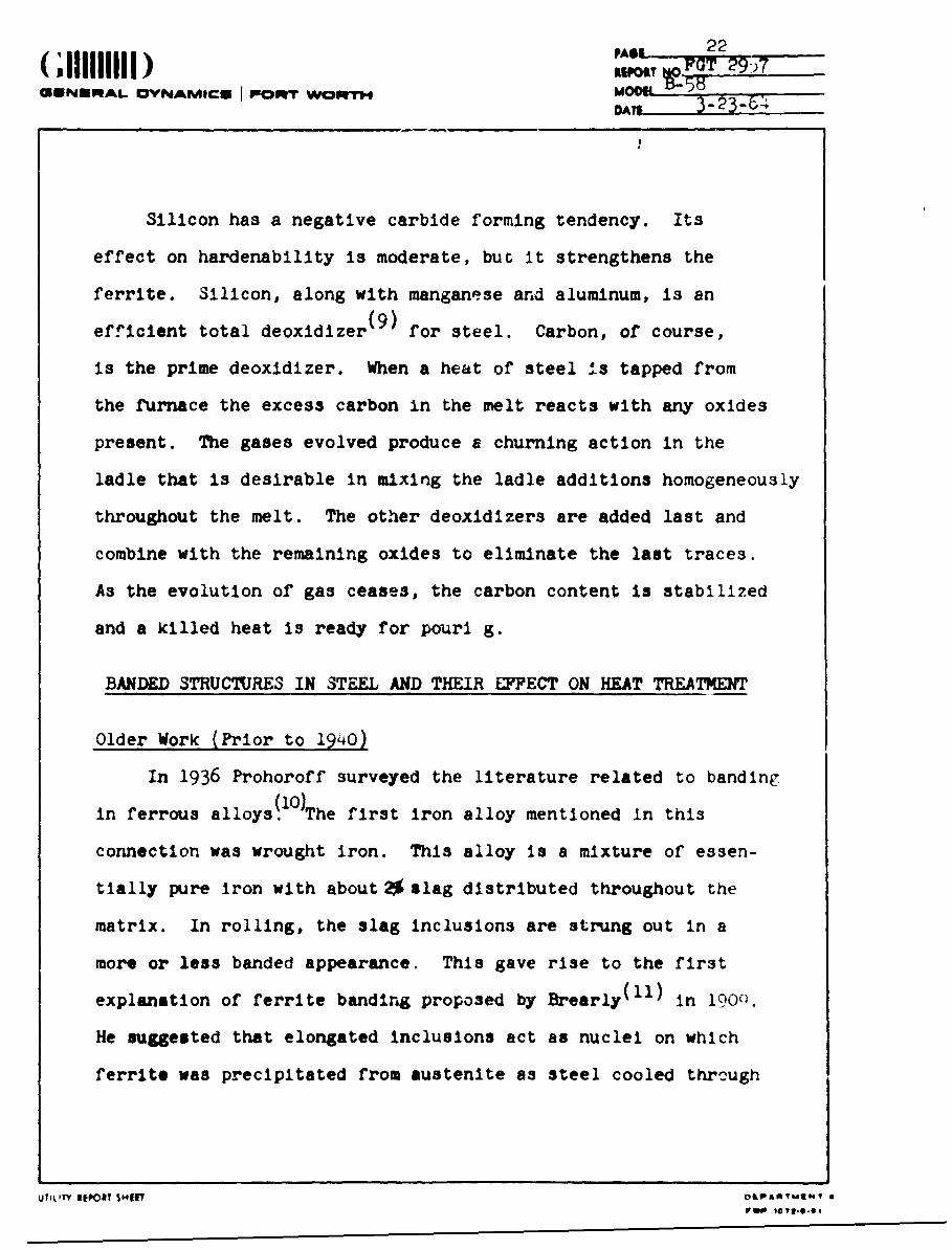
Silicon has a negative carbide forming tendency. Its
effect on hardenability is moderate, but It strengthens the
ferrite. Silicon, along with manganese and aluminum, is an(9)
efficient total deoxidizer for steel. Carbon, of course,
is the prime deoxidizer. When a heat of steel Jis tapped from
the furnace the excess carbon in the melt reacts with any oxides
present. The gases evolved produce a churning action in the
ladle that is desirable in mixing the ladle additions homogeneously
throughout the melt. The other deoxidizers are added last and
combine with the remaining oxides to eliminate the last traces.
As the evolution of gas ceases, the carbon content is stabilized
and a killed heat is ready for pourl g.
BANDED STRUCTURES IN STEEL AND THEIR EFFECT ON HEAT TREATMENT
Older Work (Prior to 1940)
In 1936 Prohoroff surveyed the literature related to banding
in ferrous alloys. O)The first iron alloy mentioned in this
connection was wrought iron. This alloy is a mixture of essen-
tially pure iron with about 2 slag distributed throughout the
matrix. In rolling, the slag inclusions are strung out in a
more or less banded appearance. This gave rise to the first
explanation of ferrite banding proposed by Brearly("l) in 19000.
He suggested that elongated inclusions act as nuclei on which
ferrite was precipitated from austenite as steel cooled thruough
UTILITY IITPOY SNT O&PAYM ft04T 6PWOe t0 &YE-6-e
(,111111) ,PAO 23UN ApoL A No FGT 29P7
GN A y _I .' B-58DAIj 3-23-64
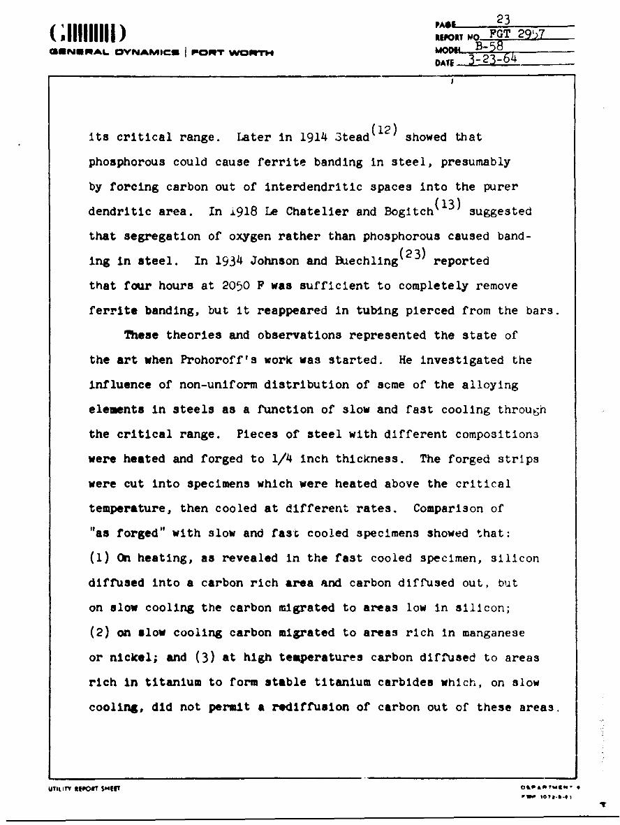
its critical range. Later in 1914 3tead(12) showed that
phosphorous could cause ferrite banding in steel, presumably
by forcing carbon out of interdendritic spaces into the purer
dendritic area. In J918 Le Chatelier and Bogitch(13) suggested
that segregation of oxygen rather than phosphorous caused band-
ing in steel. In 1934 Johnson and Buechling(23) reported
that four hours at 2050 F was sufficient to completely remove
ferrite banding, but it reappeared in tubing pierced from the bars.
These theories and observations represented the state of
the art when Prohoroff's work was started. He investigated the
influence of non-uniform distribution of some of the alloying
elements in steels as a function of slow and fast cooling through
the critical range. Pieces of steel with different compositions
were heated and forged to 1/4 inch thickness. The forged strips
were cut into specimens which were heated above the critical
temperature, then cooled at different rates. Comparison of
"as forged" with slow and fast cooled specimens showed that:
(1) On heating, as revealed in the fast cooled specimen, silicon
diffused into a carbon rich area and carbon diffused out, but
on slow cooling the carbon migrated to areas low in silicon;
(2) on slow cooling carbon migrated to areas rich in manganese
or nickel; and (3) at high temperatures carbon diffused to areas
rich in titanium to form stable titanium carbides which, on slow
cooling, did not permit a rediffusion of carbon out of these areas.
UTILITY RIPW SMu4T O&P'wgk- .
24RPOR N FUT 2557
UINYiPIAL OYNVAMICU I pHOpT WO iAf moosDATl_ 3-23-6
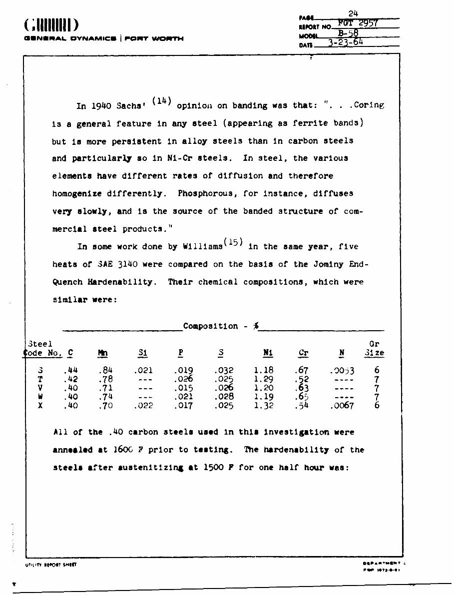
In 1940 Sachs' (14) opinion on banding was that: "...Corlng
is a general feature in any steel (appearing as ferrite bands)
but is more persistent in alloy steels than in carbon steels
and particularly so in Ni-Cr steels. In steel, the various
elements have different rates of diffusion and therefore
homogenize differently. Phosphorous, for instance, diffuses
very slowly, and is the source of the banded structure of com-
mercial steel products."
In some work done by Williams(15) in the same year, five
heats of SAE 3140 were compared on the basis of the Jominy End-
Quench Hardenability. Their chemical compositions, which were
similar were:
Composition -
Steel OrCode No. C M_ SI P S Ni Cr N 3ilze
3 .44 .84 .021 .019 .032 1.18 .67 .00o33 6T .42 .78 --- .026 .025 1.29 .52 ---- 7V .4o .71 --- .015 .026 1.20 .63 ---- 7W .4o .74 --- .021 .028 1.19 .65 ---- 7X .40 .70 .022 .017 .025 1.32 .54 .0067 6
All of the .40 carbon steels used in this Investigation were
annealed at 160& ? prior to testing. The hardenability of the
steels after austenitizing at 1500 P for one half hour was:
uTitt, floAT SOItoPomy .Pao *•-41"-
PA*E 25(;lii1i D, REPORT NO FGT 29,7
GENERA,.L OVNAMICM poop" V.,ol-I MOOM B-58S3-23-64
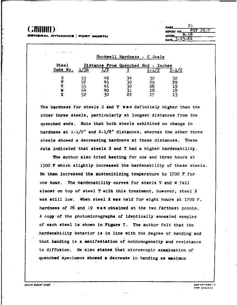
Rockwell Hardness - C Scale
Steel Distance From Quenched End - InchesCode No. 1/lb 1/2 _ I-1/2 2-1/2
S 55 49 34 32 32T 57 45 32 29 29V 55 41 30 26 19W 54 40 31 28 19X 52 30 22 17 13
The hardness for steels S and T was definitely higher than the
other three steels, particularly at longest distances from the
quenched ends. Note that both steels exhibited no change in
hardness at 1-1/2" and 2-1/2" distances, whereas the other three
steels showed a decreasing hardness at these distances. These
data indicated that steels S and T had a higher hardenability.
The author also tried heating for one and three hours at
1500 F which slightly increased the hardenability of these steels.
He then increased the austenitizing temperature to 1700 F for
one hour. The hardenability curves for steels V and W fell
almost on top of steel T with this treatment, however, steel X
was still low. When steel X was held for eight hours at 1700 F,
hardness of 26 and 19 was obtained at the two farthest points.
A copy of the photomicrographs of identically annealed samples
of each steel is shown in Figure 7. The author felt that the
hardenability behavior is in line with the degree of banding and
that banding is a manifestation of nonhomogeneity and resistance
to diffusion. He also states that microscopic examination of
quenched specimens showed a decrease in banding as maximum
UTILITY IEPONY SEIT r OPARTURNT 8

PAGL 26
UN ALOVNYAMICU PEONT warn-rm MOD,, B- 58OAI 3-23-64
172 Ik lVvI( II'\ (1 11i i .1 N 11 March
N IJ- S A 1 3140 %#.1.I A....I ! H-- 16- i~ v,- Z)U..1-# NýWw
%otx W~
FIGURE 7. Microstnjc~ture of .;teels Usedby Williams (15ý) Reduced Approx~mately 1/?
in Reprodu-t-lort.
UIt~~r S gI $4f¶ IARflow
PAGE 27(;111111111) "EOTN GItpolT No FGT 2957
INRAL MANAMICI I POI" WI Mr B-0 8DAY1 3-23-64
hardenability was approached.
In discussing the effects of temperature, the author
pointed out that in one steel which showed very slow attainment
of maximum hardness, 10 hours at 1500 F, 2.5 hours at i>.O F
and 1/2 hour at 1600 F gave identical results. The effect of
1/4 hour at 1650 F was greater than one hour at luC9 F. This
points out that 8 hours at 1700 F should be many times more
effective than 1/2 hour at 1500 F, yet steel X, after this treat-
ment, didn't attain the same hardness as steels S and T.
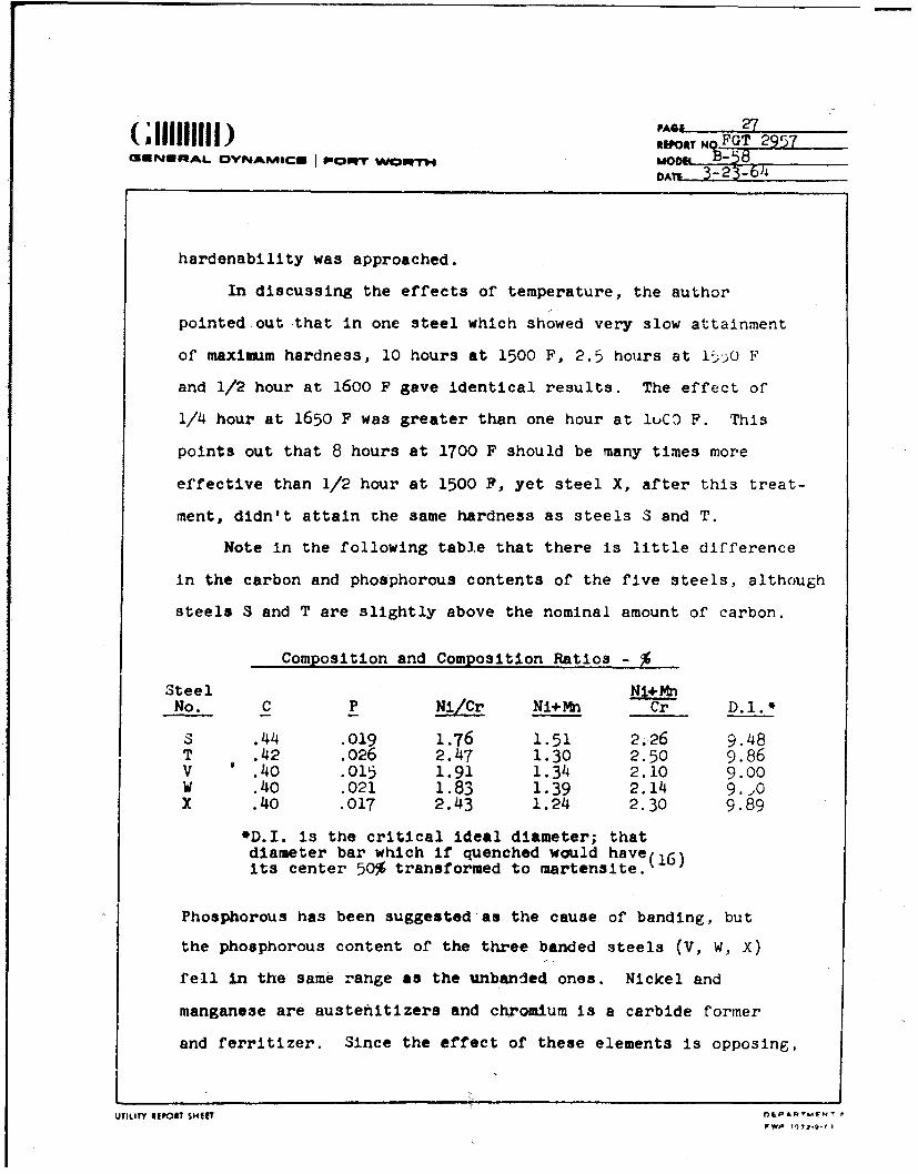
Note in the following table that there is little difference
in the carbon and phosphorous contents of the five steels, although
steels S and T are slightly above the nominal amount of carbon.
Composition and Composition Ratios -
Steel Ni+MnNo. C P Ni/Cr Ni+Mn Cr D._.*
3 .44 .019 1.76 1.51 2.26 9.48T .42 .026 2.47 1.30 2.50 9.86V .40 .015 1.91 1.34 2.10 9.00W .40 .021 1.83 1.39 2.14 9.20X .40 .017 2.43 1.24 2.30 9.89
*D.I. is the critical ideal diameter; thatdiameter bar which if quenched would have(16 )its center 50% transformed to martensite.
Phosphorous has been suggested as the cause of banding, but
the phosphorous content of the three banded steels (V, W, X)
fell in the same range as the unbanded ones. Nickel and
manganese are austehitizers and chromium is a carbide former
and ferritizer. Since the effect of these elements is opposing,
UTILITY REPOI T SHIlF nLPART.NT
VW#P 1172.9-1

PAGE____( ; IIIIIIIII ) ....... OREPORT K% FGT 29ý,7
1ERNWAL OYNA*ICS P0PorT WowTM DOOE- B-'
the ratio of the two is often used to indicate a steel's
"reacticri to heat treatment. As can be seen from the Ni/Cr and
(Ni+Mn)/Cr values, the X steel ratios were not significantly
different from those of the other steels. in fact, thrc ratio
for steel X fell between the ratios for steels S and T a3 did
the critical ideal diameter (D.I.) index of hardenability.
Comparison of the microstructures in Figure 7 show the
only significant differences in the steels that might account
for their reactions to the heat treatments. 3teel S, which
had good hardenability, exhibited ferrite thinly Pnd evenly
dispursed around the grains. Steels W and V had large areas *.
ferrite which would require more time at temperature, or higher
temperature, to diffuse the alloying elements within the dark
grains throughout the ferritic areas. The structure of steel
X, however, is more or less a mixture of the two types. The
ferrite is thinner and more well dispursed than W and V, with
some evidence of banding. This suggests that something was
impairing the dlffusion of the alloying elementz. This oource
of impairment was on a microsegregation basis.
Present Work (Since 1940)
The most extensive work done on banding was reported
in 1956.(17) Five .40 carbon steels were used In the Investiga-
tion:
IILIY REPORT SHUPAT'F
J h I REPORT NO,
GENERAL OYNAMICU I o'r" wOm,-r, MODEl
DATE
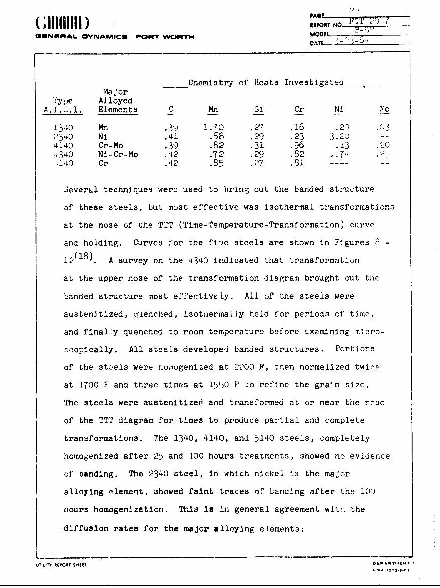
Chemistry of Heats InvestigatedMajor
Ty;)e AlloyedA. l. J. I. Elements C Mn Si Cr Ni Mo
1340 Mn .39 1.70 .27 .16 .2'1 .032340 Ni .41 .68 .29 .23 3.20 --
4140 Cr-Mo .39 .82 .31 .96 .i3 .204340 Ni-Cr-Mo .42 .72 .29 .82 1.74 .2-).140 Cr .42 .85 .27 .81 ------
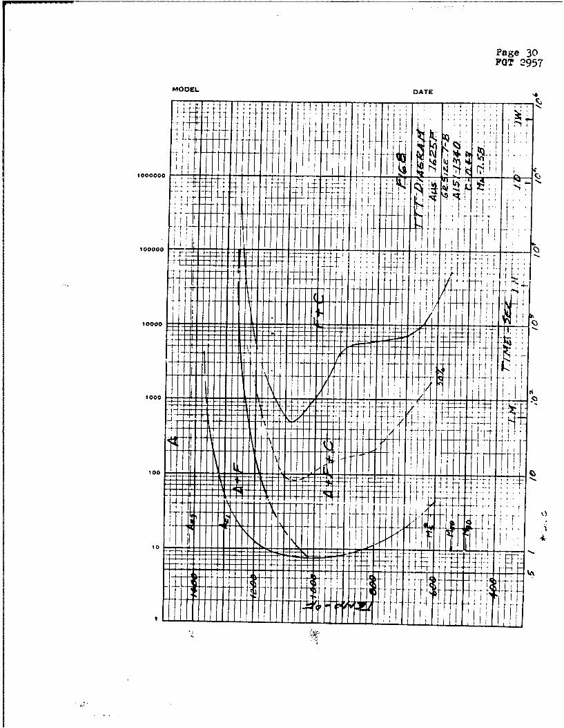
3everal techniques were used to bring out the banded structure
of these steels, but most effective was isothermal transformations
at the nose of the TTT (Time-Temperature-Transformation) curve
and holding. Curves for the five steels are shown in Figures 8 -
1_18). A survey on the 4340 indicated that transformation
at the upper nose of the transformation diagram brought out the
banded structure most effecýtivcly. All of the steels were
austenJtized, quenched, isothiermally held for periods of time,
and finally quenched to room temperature before £xamining micro-
scopically. All steels developed banded structures. Portions
of the ste.els were homogenized at 22?00 F, then normalized twice
at 1700 F and three times at 1550 F co refine the grain size.
The steels were austenitized and transformed at or near the no3eof the TTT diagram for times to produce partial and complete
transformations. The 1340, 4140, and 5140 steels, completely
homogenized after 2) and 100 hours treatments, showed no evidence
of banding. The 2340 steel, in which nickel is the major
alloying element, showed faint traces of banding after the 10(
hours homogenization. This is in general agreement wltft the
diffusion rates for the major alloying elements:
UTILITY REPORT SHEET DIEPARTIP4ENT A,
FWP' 1072-0-0 1
Page 30POT 2957
MODEL DATE '4
10000 [+ 1t I t
10000
t O O 4 -
100 fLL~~L~ '+to+1

,~. Pas* 31POT~ 2957
IOS DATUKIf
1000000
10 004~-tI
-T = 3L
100SJ
_1 1 1 I I
t I
YI
10b

Page 32POT 2957
MODEL DATE 1
1000000
j :: :~1~ ~ tj
10000V4 A + z§ 1
1000++z)
4- t <~ r
tH
+

Page 33FGT 2957
MODEL DATE
+ 4:
1 0 0 0 0 ..j .
100000 t-- t f-....4*, +-- --t4
J -4,
+I 4
444
100
~~I T
44~~ ~ +I 4~p,

Page Y4~FGT 295Y
MOCEL DATE
4, 4
.~-146* ii.**I* I~tI~Qr¾ -. oo tr .okk V)
101010000 -j - -
II
tio
so1 I I
tot
~77
~,* <*6

mUNUmAL @YNAMic I viopwr w MODS 3o64
RATES OF DIFFUSION FOR ALLOYING ELEMENTS AT 2200 F
Element D- Cm2 /SEC
Silicon (2370 F) 1.5 x 10⁻⁹Chromium 1.4 x I0- 9
Molybdenum 9.0 x 10⁻¹⁰Manganese 1.36 x 10⁻¹⁰Nickel 3.75 x 10⁻¹¹
Iron (Self Diffusion) 3.)6 x i0-I1
When found, the banding in the 1340, 4140 and 5140 was
more marked, while the ferrite and pearlite bands in 2340
appeared more diffuse. It must be remembered that the heat
treatment used in these tests was intended to produce the maximum
variation in structure. Had a simple austenitize quench and
temper heat treatment been used, the banding would have appeared
as a less marked difference in the microstructure of the tempered
martensite.
The 4340 steel was homogenized for 5, 16, 25, 50, 75, 100
and 200 hours, then normalized to refine the grain size in the
same manner as the other steels. The degree of homogenization,
as evaluated by the martensite or direct quench technique and
ferrite transformation technique, was judged to be complete between
i and 16 hours at 2200 F. However, using the pearlite trans-
formation there was some banding after 200 hours of homogenization.
Referring to Figure 11, note that transforming at 1200 F
the first field encountered Is ANF. In this field ferrite is
being rejected from the austenite. On quenching from this region
the remainder of the untransformed austenite transforms to
UTIULTV Rpm SHI O&Prl"Vh SfWlJ O l--

PA*' 36Itrip No- FGT 29 7
GENERAL O•NAMIC I FORT Wr TH MoATL ,B-DATL• 3-23-64
martensite. Continuing transformation at 1200 F, the next
field to be encountered is A+F*C. In this field the austenIte
is transformed to ferrite plus cementite (iron carbide)as plateietj
within the grains called pearlite.
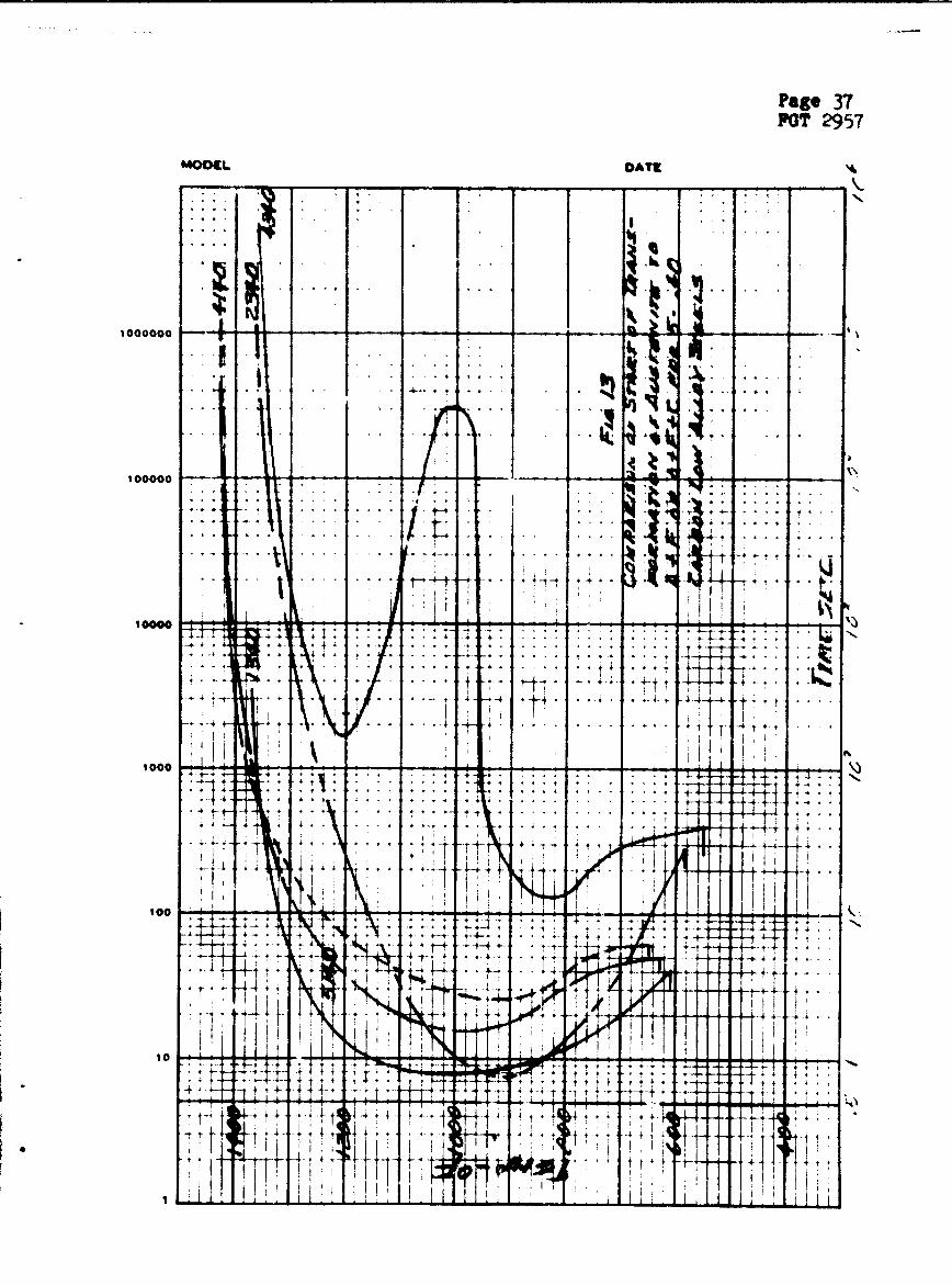
The start of transformation and end of transformation for
the five steels are shown by Figures 13 and 14. Note the effect
of the alloying elements on the shape of the TTT curves of the
five steels. Consider the other steels in relation to the 1•,•,
steel. Chromium and molybdenum in )140 and 4140 cause the curves
to be shifted to the right requiring longer times to start
the transformation of austenite at 1200 F. Above the nose oi
the curve the temperature of complete transformation from austenltL
is very close for 4140, 5140 and 1340, Figure 14. Nickel, as in
P?340, has little effect on the time, but the temperature is
lowered considerably. The combined effect of the nickel, chron'um.
and moiybdenum is to lower temperature and increase time as snown
by 4340. They produce the "bay" between 800 and 1000 F in wr~ih
4austenite will remain stable for 3 x 10 seconds or 8 hours.
At 1200 F an area of the microstructure, lean In any or, all
of the alloying elements of a 4340 steel, woulo start to t-'an:3-
form faster than a richer area. In addition, the transformation
would be completed sooner. The only steel for which transfor-
mation at 1200 F would not be complete in the range of the
diagrams is 2340. Referring to Figure 9, this transformation
remains In the AeF region for the entire time range of the diagram.
. U UTILItY SHI P ou0i uw ' epop ts?'044
Page 37M0 2957
MODEL DATZ
-4 - - +
1 4
- -4 -4 4
.. *-4--* ~4-
too. :~
+ 44
4 .. v 4.
*~~ ~ 4 . .-

ftge 38M0 2957
DATE
4,
- . . . .
S4 +
- - - -
It'
-- 4~~. 4.+4 .
t I'
_ H i I triP I I II

PAO, n 39(I11111111) U,.O.
*nNISAL OVh~IA S I POlnrr W TMOM_- -3-
That the transformation is never complete indicates that the
transformation is very sluggish. It also indicates that nickel I
is the cause of the banding as revealed by the pearlite technique
even though pearlite is not f'ormed by a 2340 steel at 1200 F.
While there is not complete segregation of the alloying elements,
the effect of nickel enrichment can only be described as a
tendency to shift the TTT diagram toward the characteristic of
the steel using that element alone. This shift and the slow
diffusion rate o,' nickel as shown by the non-homogeneity of
2340 steel, and the complete homogeneity of 1340, 4140, 4340 and
5140 steels, all point toward nickel as the cause of banding.
Tensile tests were done on "as received" and homogenized
4340 In the normalized condition. The strengths did not vary
significantly, but the elongation was increased from 18.6 to
20.6% in the longitudinai direction and from 12.8 to 15.39 in
the transverse direction. The charpy impact strength was increased
from 82 to 86 ft. - lbs. In the longitudinal direction and from
31.4 to 39 ft. - lbs. In the transverse direction. The authors
concluded that homogenization produced an Improvement In transverse
dutility, but that the degree of Improvement was not commercially
significant.
A considerable aswmnt of work was done by Wysas(9) in
3witterland on low alloy steels. Castings were hot worked by
three amounts, 15:1, 100:1 and 650:1. The samples were austeni-
tized and isothermally transformed at 1270 F. The primary band
m m n i

40
('011111111) TWO FGT 29LSUINISAL CVNAM$C* PORT WOWYS4
spacing was inversely proportional to the square root of the
degree of deformation. The banding was found to disappear as
the band spacing approached the grain size of the steel. Further(20)
work reported lbter indicated that for unalloyed steeW
phosphorous segregated areas favored ferrite formation. In
alloyed steels, he reported that ferrite formeJ in al.lo.-r ,or
dendrite areas from the original casting. He reported that flne
grain size, greater amounts of workir4z and low segregation In
the original casting favored unbanded steel, while the opposite
favored banding.
In work done in Germany dbout the same time, Plocklnger(211
worked with plain carbon and Cr-Mo steels. By diffusion
annealing (temperature not reported in abstract, but presumably
in 2000 P range) (p-: 3U hours the plain carbon and alloyed steel
were homogenired. He reported that chromium and kolybdenum.
had a strong Influr-'e on banding.
Yn the latest work found(22), three steels werC cast under
conditions to give fully columnar, partially columnar and eqila.:eAd.
and fully equiax-d structures. The steel used was a
Ni-Cr-oO, .30-.35 carbon steel which is sledlar to 433• or .v
under AISI designation. The Ingots wer' rorged asd saapleb were
examined as cast, as forged, and as heat treated by austenlt.i"'n?
quenching. Electron microprob* analyses were made of the structures.
an , stemlytasomiga 10Pfr1 mluts the

41PAGL_.
CNIENINPAL 0YNAMIC:IS 1 rmopwr wCoprrT- OAT P m-53-8
It was found that nickel and chromium segregated much more in
the equlaxed areas of the three castingsthan in the columnar
&reas. Banding developed more severely in equiaxed zones of
the castings. Forging which reduced segregation was more effective
in reducing the chromium segregation than the nickel.
CONCLUSIONS
1. Banding is caused by segregation of the alloying elements
4n ingots during solidification.
2. During 3ubsequent hot working operations the segregation
is aligned in the direction of working and results in a banded
appearance of the microstructure.
3. The diffusion rates of the alloying elements in steel
control the homL.1nization of the ingot, chromium and molybdenum
homogenizing readily and zx:.'fr',l very slowly.
4. The increase In properties by homogenizing does not
warrant the involved process of homogenizing,then reflrning the
resulting large grain size.
5. The fact that design can orient the plane of maximun, stress
in a direction parallel to the working direction of the stock
or forging, it is felt, has lead to the economic Infeasibility
of performing the very involved and costly task of homogenization.
This beboves tne designer to take as much advantage of controlling
grain flow as possible. ( / - -/ v
UTILITY I IPO IT SHIET OLPARTMKNT T
I 107'-S-f
PA&i- 42(111111111 D.U, OT,95,,NYPAL .YNAMIC0 I PaCPaWTR"H mair, _ __-58D0n- 3- 23- 64
BIBLIOGRAPHY
1. G. W. Form and J. F. Wallace, "Solidification of Mctals,"
Modern Castings, Vol. 37)No. 4, April 1960, p 145.
2. C. W. Briggs, "Solidification of Steel Castings," bid.p.157.
3. B. Chambers, "Melting and Freezing," J. met., Vol. 6 No. 5,
May 1954, p 519.
4. J. G. Mravec, "Control of Segregation and Ingot Structures
in Low Alloy Steels," •ality Reguirement of Super Duty
Stels, AIME Conference at Pittsburg 1950, Interscience
Publishers, New York, 1959, p 183.
5. A. Kohn and J. Philbert, "The Solidification of Alloys,"
Metal Treatment and Drop Forging (English), Vol. 27, Au6-Sept
1960, pp 327-334, 351-355.
6. E. C. Bain and H. W. Paxton, .Aloying Elements in Steel,
ASM, Cleveland, Ohio, 1961, p 18 & 105.
7. ibid~p 112
8. ibid pp 243-7
9. C. H. Samans, "Enineering-Metals and Their Alloys,"
Macmillan Co., New York, 1949, p 213.
10. A. V. Prohoroff, "Ferrite Banding in Forged and Rolled Steel,"
Netallurgia, Vol. 13, April 1936, pp 179-181.
UTILITy RIPORIT SHIFT V&PANRLARNT 6IrwP O7-O
PA"I 43 25RPORT UT N5
MUNIPAL OVFJAMIC= I I4*nT wnrm M} .Y5.OATE 3-23_64
BibliograPhy Cont 'd.
11. Brearly, Proceedinas of the Sheffield Soc. of Eng. and
Met., Vol. 2, 1909, p 56.
12. Stead, Journ. of the Iron and Steel Inst., Vol I, 1918,
p 287.
13. Le Chatelier and Bogitch, Comptes Rendus, Vol. 167, 1918
p 472.
14. G. Sachs and K. R. Van Horn, Practical Metallurzy,
ASM, Cleveland, Ohio, 1940, p 44 & 49.
15. G. T. Williams, "Hardenability Variation in Alloy Steels -
Some Investigations with the End Quench rest," Trans ASM,
Vol. 28, 1940, p 170.
16. 'Republic Alloy Steels Cleveland, Ohio, 1961, p 78.
17. C. F. Jatczak, D. J. Girardi, and E. S. Rowland, "On Banding
in Steel," Trans. ASM, Vol. 48, 1956, p 279.
18. Supplement to the Atlas of Isothermal Transformation
Diagrams, US Steel, Pittsburg, Pa., 1953.
19. Urs Wyss, "The Effect of the Primary Band Spacings and of
the Austenitic Grain Size on the Formation of the Ferrite -
Pearlite Band Structure," Schweizer Archiv for Angewandte
Wissenshaft und Technik, Vol. 22, p 258-60, 1956.
20. Urs Wyss, "Cause and Effect of Secondary Band Structure in
Steel," Harterei Tchnische Mitteilungen, Vol. 15 No. 1,
(1960), p 14-19.
UTILITY REPOI1T$E DO'ARTMjNT S
A PAA 44S(;IIIIIIIII) ,,, PO... ...uoXM, HID F_0T 29ýjTCEP40MAL OYNAMICS I PIOWV WOWfl4
Bibliography Cont'd.
21. E. Plockinger and A. Randak, "Banded Structure in Plain
Carbon and Alloy Structural Steels," Stahl und Eigen,
Vol. 78, (1958), p 1141-54.
22. F. A. Malagari, "Banding in Steel" (A Digest of "Banding
in a 1-1/2% Ni-Cr-Mo Steel" by T. B. Smith,et al, J_ n
Iron and Steel Inst., Vol. 1963, p 602), Metals Progress,
Vol. 58 No. 3, March 1963.
23. Johnson and Buechling, Trans. ASM, Vol. XXII, No. 3 (1934)
p 249.
c
UTILITY .POIT SM§Il OILDPARTRNT