Embed Size (px)
Citation preview

LM3519-+ Cin
4.7 PF
L2.2 PH D
Cout
1 PF
Gnd LED_rtn
Vout
Vin Sw
En
Vin
Vout
Vx
LogicVoltageSignalInput
LM3519
www.ti.com SNVS394B –AUGUST 2005–REVISED MAY 2013
LM3519 High Frequency Boost White LED Driver with High-Speed PWM BrightnessControl
Check for Samples: LM3519
1FEATURES DESCRIPTIONThe LM3519 drives up to 4 white LEDs with constant
2• Drives 2 to 4 LEDs at 20mAcurrent to provide LCD backlighting in handheld
• Up to 30kHz PWM Dimming Control Capability devices. The LED current is internally set to 20mA.• >80% Peak Efficiency The series connection allows the LED current to be
identical for uniform brightness and minimizes the• Up to 8MHz Switching Frequencynumber of traces to the LEDs. Brightness control is• Small External Components: 1µH - achieved by applying a PWM signal on enable with
3.3µH(typ.2.2μH) Inductor and 1µF Output frequencies up to 30kHz.Capacitor
The LM3519 features a proprietary PFM regulation• True Shutdown Isolationarchitecture with switching frequencies between
• Over-Voltage Protection 2MHz to 8MHz, minimizing inductor size.• Wide Input Voltage Range: 2.7V to 5.5V Over-voltage protection circuitry and high frequency• Small Footprint SOT-23 Package operation permit the use of low-cost small output
capacitors. During shutdown, the output isAPPLICATIONS disconnected from the input in order to avoid leakage
current path through the LEDs to ground.• LCD, White LED Backlighting on MobileThe LM3519 is available in a tiny 6-pin SOT-23Phonespackage.• Digital Still Cameras and PDAs
• General Purpose LED Lighting in HandheldDevices
Typical Application
Figure 1. Typical Application Circuit
1
Please be aware that an important notice concerning availability, standard warranty, and use in critical applications ofTexas Instruments semiconductor products and disclaimers thereto appears at the end of this data sheet.
2All trademarks are the property of their respective owners.
PRODUCTION DATA information is current as of publication date. Copyright © 2005–2013, Texas Instruments IncorporatedProducts conform to specifications per the terms of the TexasInstruments standard warranty. Production processing does notnecessarily include testing of all parameters.

2
61
5
3 4
LM3519
SNVS394B –AUGUST 2005–REVISED MAY 2013 www.ti.com
Connection Diagram
6-Lead SOT-23 Package
Top View
PIN DESCRIPTIONSPin # Name Description
1 En Device Enable Connection
2 Gnd Ground Connection
3 VOUT Output Voltage Connection
4 LED_rtn White LED Current Sensing Input Connection
5 SW Drain Connection of the Internal Power Field Effect Transistor (FET) Switch
6 VIN Input or Supply Voltage Connection
These devices have limited built-in ESD protection. The leads should be shorted together or the device placed in conductive foamduring storage or handling to prevent electrostatic damage to the MOS gates.
Absolute Maximum Ratings (1)
VIN , En, & LED_rtn Pin −0.3V to +6.5V
VOUT , Sw Pin −0.3V to +21V
Maximum Junction Temperature, (TJ-MAX) +150°C
Storage Temperature Range −65°C to +150°C
ESD Rating (2)
Human Body Model: 2kVMachine Model: 200V
(1) Absolute maximum ratings indicate limits beyond which damage to the device may occur. Operating Ratings are conditions under whichoperation of the device is ensured. Operating Ratings do not imply ensured limits. For ensured performance limits and associated testconditions, see the Electrical Characteristics table.
(2) The human body model is a 100pF capacitor discharged through a 1.5kΩ resistor into each pin. The machine model is a 200pFcapacitor discharged directly into each pin.
Operating Ratings (1)
Junction Temperature (TJ) Range −40°C to +125°C
Ambient Temperature (TA) Range −40°C to +85°C
Input Voltage Range 2.7V to 5.5V
(1) Absolute maximum ratings indicate limits beyond which damage to the device may occur. Operating Ratings are conditions under whichoperation of the device is ensured. Operating Ratings do not imply ensured limits. For ensured performance limits and associated testconditions, see the Electrical Characteristics table.
Thermal Properties (1)
Junction-to-Ambient Thermal Resistance (θJA) 220°C/W
(1) The maximum allowable power dissipation is a function of the maximum junction temperature, TJ(MAX), the junction-to-ambient thermalresistance, θJA, and the ambient temperature, TA. See Thermal Properties for the thermal resistance. The maximum allowable powerdissipation at any ambient temperature is calculated using: PD(MAX) = (TJ(MAX) – TA)/θJA. Exceeding the maximum allowable powerdissipation will cause excessive die temperature.
2 Submit Documentation Feedback Copyright © 2005–2013, Texas Instruments Incorporated
Product Folder Links: LM3519

LM3519
www.ti.com SNVS394B –AUGUST 2005–REVISED MAY 2013
Electrical Characteristics (1) (2)
Limits in standard typeface are for TJ = +25°C. Limits in bold typeface apply over the full operating junction temperaturerange (−40°C ≤ TJ ≤ +125°C). VIN = 3.6V, unless otherwise stated.
UniSymbol Parameter Conditions Min Typ Max ts
IQ Supply Current Shutdown: VEN = 0V 0.1
Not Switching: VEN = 1.8V 360 500 µASwitching: VEN = 1.8V, LED_rtn current = 550 90030mA
ILED(TOL) LED Current Tolerance/Variation VIN = 3.6V, 2.2μH, –10 5.5 10 %4LEDs
OVP Over-Voltage Protection Threshold OVP ON 18 18.9 20 VOVP OFF 17.8 18.6 19.8
ILIM Switch Current Limit L = 2.2µH 750 mA
RDS(ON) Power NMOS Switch ON Resistance 455 mΩILEAKAGE Switch Leakage VSW = 3.6V, VEN = 0V 0.1 2 µA
RLED_rtn(ON) LED_rtn NMOS Switch ON Resistance 8.0 ΩFS Switching Frequency ILED = 20 mA , L = 1μH MH5.44LEDs z
IEN Enable Pin Bias Current (3) VEN = 0V 0.1 µAVEN = 1.8V 1.1 2
En Enable Threshold Device On 0.9 VDevice Off 0.3
(1) Absolute maximum ratings indicate limits beyond which damage to the device may occur. Operating Ratings are conditions under whichoperation of the device is ensured. Operating Ratings do not imply ensured limits. For ensured performance limits and associated testconditions, see the Electrical Characteristics table.
(2) Min and max limits are ensured by design, test, or statistical analysis. Typical numbers are not ensured, but do represent the most likelynorm.
(3) Current flows into the pin.
Copyright © 2005–2013, Texas Instruments Incorporated Submit Documentation Feedback 3
Product Folder Links: LM3519

+
-
ERRORAMPLIFIER
ON-TIMEGENERATOR
OVERVOLTAGE
PROTECTION
DRIVERLOGIC
CURRENTLIMIT
R
S
R
Q
En
LED_rtn
Vout
Gnd
Vin
Sw
N2Vin
N1N3Vin
IREF
VREF1
2
3
4
5
6
LM3519
SNVS394B –AUGUST 2005–REVISED MAY 2013 www.ti.com
BLOCK DIAGRAM
Figure 2. Block Diagram
Circuit Description
The LM3519 is a step-up converter for white LED applications that uses a unique and proprietary pulsefrequency modulation (PFM) architecture to optimize high efficiency at high frequency operation. Unlike mostPFM architecture implementations, the LM3519’s unique architectural implementation results in non-pulseskipping variable frequency operation. The regulator is forced to operate at the edge of Continous ConductionMode (CCM). The error amplifier will set the end of the on-time (IPEAK of inductor) based on the load (LEDs)current. During this operation, the inductor current ramps up and reaches a peak current at end of the on-time. Atthis point, the internal power switch is turned off until the inductor current reaches zero, and the cycle repeatsagain. The switching frequency is set based on the charge (on-time) and discharge(off-time) of the inductorcurrent. The frequency can range between 2MHz to 8MHz over the operating input range.
The LM3519 operation can be best understood through an examination of the block diagram in Figure 2. WhenLED current is out of regulation, the LED_rtn voltage falls below or rises above the internal reference voltage(VREF). The error amplifier will output a signal to increase or decrease the proper on-time duration of N1 powerFET. This correction allows the inductor's stored energy to increase or decrease to a sufficient level that whentransferred to the load will bring the LED_rtn current back into regulation.
During steady-state operation for a typical switching cycle, the oscillator sets the driver logic and turns on N1power device. N1 conducts current through the inductor and reverse biases the external diode. The LED currentis supplied by the output capacitor when N1 is conducting. Once N1 on-time period is concluded, the internalpower device is turned off and the external diode is forward baised. The inductor current then flows through thediode to the LED load to replenish the output capacitor and keep the LED current regulated at the trimmedtarget.
4 Submit Documentation Feedback Copyright © 2005–2013, Texas Instruments Incorporated
Product Folder Links: LM3519

-4
-2
0
2
4
10
2.7 3.0 3.3 3.6 3.9 4.2 4.5
VIN (V)
AC
CU
RA
CY
(%
) 6
8
25°C
85°C
-40°C
0
2
4
6
8
16
2.7 3.0 3.3 3.6 3.9 4.2 4.5
VIN (V)
AC
CU
RA
CY
(%
)
1 PH10
12
14
3.3 PH
2.2 PH
50
60
70
80
90
2.5 3.0 3.5 4.0 4.5 5.0 5.5
VIN (V)
EF
FIC
IEN
CY
(%
)
1 PH
2.2 PH3.3PH
1.5 PH
100
3 LEDs
50
60
70
80
90
2.5 3.0 3.5 4.0 4.5 5.0 5.5
VIN (V)
EF
FIC
IEN
CY
(%
) 3.3PH
1.5 PH
100
1 PH
2 LEDs
50
60
70
80
90
2.5 3.0 3.5 4.0 4.5 5.0 5.5
VIN (V)
EF
FIC
IEN
CY
(%
)
1 PH
2.2 PH3.3PH
1.5 PH
4 LEDs
75
77
79
81
83
85
2.7 3.1 3.5 3.9 4.3 4.7 5.1 5.5
VIN (V)
EF
FIC
IEN
CY
(%
)
-40°C
85°C
4 LEDs
25°C
LM3519
www.ti.com SNVS394B –AUGUST 2005–REVISED MAY 2013
Typical Performance Characteristics(See Figure 1: VIN = 3.6V, CIN = 4.7µF and COUT = 1µF, L = 2.2µH and 4 LEDs. TA = +25°C, unless otherwise stated.)
Efficiency Efficiencyvs vsVIN VIN
Efficiency Efficiencyvs vsVIN VIN
IOUT_ACCURACY IOUT_ACCURACYvs vsVIN VIN
Copyright © 2005–2013, Texas Instruments Incorporated Submit Documentation Feedback 5
Product Folder Links: LM3519

5 15 25 35 45 55 65 75 85 95
DUTY CYCLE (%)
2
5
8
11
14
17
20
23
I OU
T (
mA
)
20 kHz
50 kHz
30 kHz
EN = 20 kHz, 30 kHz, and 50 kHz
5 15 25 35 45 55 65 75 85 95
DUTY CYCLE (%)
1
4
7
10
13
16
19
22
I OU
T (
mA
)
EN = 100 Hz and 500 Hz
19.5
20.0
20.5
21.0
21.5
22.0
2.7 3.0 3.3 3.6 3.9 4.2 4.5
VIN (V)
I OU
T (
mA
)
25°C
85°C
-40°C
5 15 25 35 45 55 65 75 85 95
DUTY CYCLE (%)
1
4
7
10
13
16
19
22
I OU
T (
mA
) EN =100 Hz and 500 Hz
2.5 3.0 3.5 4.0 4.5 5.0 5.5
VIN (V)
I OU
T (m
A)
1 PH
3.3 PH
1.5 PH
2.2 PH
16.0
18.0
20.0
22.0
24.0
26.0
28.0
30.0
4 LEDs
1.5 PH
2.5 3.0 3.5 4.0 4.5 5.0 5.5
VIN (V)
I OU
T (m
A)
3.3 PH
16.0
18.0
20.0
22.0
24.0
26.0
28.0
32.0
2.2 PH
1 PH
30.0
3 LEDs
LM3519
SNVS394B –AUGUST 2005–REVISED MAY 2013 www.ti.com
Typical Performance Characteristics (continued)(See Figure 1: VIN = 3.6V, CIN = 4.7µF and COUT = 1µF, L = 2.2µH and 4 LEDs. TA = +25°C, unless otherwise stated.)
IOUT IOUTvs vsVIN VIN
IOUTIOUT vsvs PWM Duty CycleVIN (VIN = 3.6V, L = 2.2µH)
IOUT IOUTvs vs
PWM Duty Cycle PWM Duty Cycle(VIN= 3.6V, L = 2.2µH) (VIN = 3.6V, L = 1µH)
6 Submit Documentation Feedback Copyright © 2005–2013, Texas Instruments Incorporated
Product Folder Links: LM3519

2.7 3.0 3.3 3.6 3.9 4.2 4.5
VIN (V)
I PE
AK
(m
A)
1 PH
3.3 PH
2.2 PH
4 LEDS
100
150
200
250
300
350
400
2.7 3.1 3.5 3.9 4.3 4.7 5.1 5.5
VIN (V)
FR
EQ
UE
NC
Y (
MH
z)
3.3 PH
2.2 PH
1 PH
1.5
4.5
6.0
7.5
9.0
10.5
3.0
4 LEDs
2.7 3.0 3.3 3.6 3.9 4.2 4.5
VIN (V)
FR
EQ
UE
NC
Y (
MH
z)
2 LEDS
0.0
1.0
2.0
3.0
4.0
5.0
6.0
7.0
8.0
9.0
3.3 PH
2.2 PH
1 PH
4.0
5.0
6.0
7.0
8.0
9.0
2.7 3.1 3.5 3.9 4.3 4.7 5.1 5.5
VIN (V)
FR
EQ
UE
NC
Y (
MH
z) -40°C and 85°C
4 LEDs1 PH,
25°C
2.7 3.0 3.3 3.6 3.9 4.2 4.5
VIN (V)
FR
EQ
UE
NC
Y (
MH
z)
3.3 PH
3 LEDS
2.2 PH
1 PH
0.0
1.0
2.0
3.0
4.0
5.0
6.0
7.0
8.0
9.0
10 20 30 40 50 60 70 80 90 100
DUTY CYCLE (%)
1
4
7
10
13
16
19
22
25
I OU
T (
mA
)
50 kHz
20 kHz
30 kHz
EN = 20 kHz, 30 kHz, and 50 kHz
LM3519
www.ti.com SNVS394B –AUGUST 2005–REVISED MAY 2013
Typical Performance Characteristics (continued)(See Figure 1: VIN = 3.6V, CIN = 4.7µF and COUT = 1µF, L = 2.2µH and 4 LEDs. TA = +25°C, unless otherwise stated.)
IOUTvs Switching Frequency
PWM Duty Cycle vs(VIN = 3.6V, L = 1µH) VIN
Switching Frequency Switching Frequencyvs vsVIN VIN
Switching Frequency Peak Inductor Currentvs vsVIN VIN
Copyright © 2005–2013, Texas Instruments Incorporated Submit Documentation Feedback 7
Product Folder Links: LM3519

-40 -20 0 20 40 60 80 100
TEMPERATURE (°C)
I Q N
ON
SW
ITC
HIN
G (P
A)
320
360
370
380
390
400
350
340
330
-40 -20 0 20 40 60 80 100
TEMPERATURE (°C)
I Q S
WIT
CH
ING
(P
A)
500
520
540
560
580
600
510
530
550
570
590
2.7 3.1 3.5 3.9 4.3 4.7 5.1 5.5
VIN (V)
CU
RR
EN
T L
IMIT
(m
A)
25°C and -40°C
85°C
700
800
900
1000
1100
1200
2.7 3.1 3.5 3.9 4.3 4.7 5.1 5.5
VIN (V)
CU
RR
EN
T L
IMIT
(m
A)
3.3 PH
2.2 PH
1 PH
600
800
900
1000
1100
1200
700
2.7 3.0 3.3 3.6 3.9 4.2 4.5
VIN (V)
I PE
AK
(m
A)
1 PH
3.3 PH
2.2 PH
3 LEDS
100
150
200
250
300
350
400
2.7 3.0 3.3 3.6 3.9 4.2 4.5
VIN (V)
I PE
AK
(m
A)
1 PH
3.3 PH
2.2 PH
2 LEDS
100
150
200
250
300
350
400
LM3519
SNVS394B –AUGUST 2005–REVISED MAY 2013 www.ti.com
Typical Performance Characteristics (continued)(See Figure 1: VIN = 3.6V, CIN = 4.7µF and COUT = 1µF, L = 2.2µH and 4 LEDs. TA = +25°C, unless otherwise stated.)
Peak Inductor Current Peak Inductor Currentvs vsVIN VIN
Current Limit Current Limitvs vs
VIN (4LEDs, 1µH) VIN
Iq (non switching) Iq (switching)vs vs
Temperature Temperature
8 Submit Documentation Feedback Copyright © 2005–2013, Texas Instruments Incorporated
Product Folder Links: LM3519

-40 -20 0 20 40 60 80 100
TEMPERATURE (°C)
LED
SW
ITC
H R
DS
ON
(:
)
6
7
8
9
10
11
-40 -20 0 20 40 60 80 100
TEMPERATURE (°C)
PO
WE
R S
WIT
CH
RD
SO
N (
m:
)
320
420
470
520
570
620
370
LM3519
www.ti.com SNVS394B –AUGUST 2005–REVISED MAY 2013
Typical Performance Characteristics (continued)(See Figure 1: VIN = 3.6V, CIN = 4.7µF and COUT = 1µF, L = 2.2µH and 4 LEDs. TA = +25°C, unless otherwise stated.)
LED Switch RDS_ON Power Switch RDS_ONvs vs
Temperature Temperature
Start-up, (VIN = 3.6V, 4LEDs, 2.2µH) Start-up (VIN = 3.6V, 4LEDs, 3.3µH)
Start-up (VIN = 3.6V, 2LEDs, 3.3µH) Start-up, (VIN = 3.6V, 2LEDs, 2.2µH)
Copyright © 2005–2013, Texas Instruments Incorporated Submit Documentation Feedback 9
Product Folder Links: LM3519

LM3519
SNVS394B –AUGUST 2005–REVISED MAY 2013 www.ti.com
Typical Performance Characteristics (continued)(See Figure 1: VIN = 3.6V, CIN = 4.7µF and COUT = 1µF, L = 2.2µH and 4 LEDs. TA = +25°C, unless otherwise stated.)
Typical Switching Waveform Typical Switching Waveform(VIN = 3.6V, 4LEDs, 3.3µH) (VIN = 3.6V, 4LEDs, 2.2µH)
Typical Switching Waveform Typical Switching Waveform(VIN = 3.6V, 3LEDs, 2.2µH) (VIN = 3.6V, 2LEDs, 2.2µH)
Typical Switching Waveform Typical Switching Waveform(VIN = 3.6V, 3LEDs, 1µH) (VIN = 3.6V, 4LEDs, 1µH)
10 Submit Documentation Feedback Copyright © 2005–2013, Texas Instruments Incorporated
Product Folder Links: LM3519

LM3519
www.ti.com SNVS394B –AUGUST 2005–REVISED MAY 2013
APPLICATION INFORMATION
Capacitor Selection
To minimize output and input voltage ripple, low equivalent series resistance (ESR) ceramic capacitors are thebest choice to use for the input and output filters. For most display applications, a 4.7µF capacitor isrecommended for CIN and 1µF for COUT .
Larger output capacitors can be used to reduce ripple voltage. To ensure good performance, a minimum of0.47µF COUT is required to trade off for large ripple voltage. Care must be taken to account for the truecapacitance of a multilayer ceramic capacitor. Smaller case size capacitors typically have less capacitance for agiven bias voltage as compared to a larger case size capacitor with the same bias voltage. Please confirm withcapacitor manufacturer data before selecting the capacitor.
Recommended capacitor manufacturers include but are not limited to:
Table 1.
Manufacturer Description Case Size
AVX 06033D105MAT-25V 0603
06036D475MAT-6.3V 0603
TDK C2012X5R1A475M-10V 0805
Taiyo Yuden TMK212BJ105KG-J 0805
EM212BJ475MG-16V 0805
muRata GRM40-034B105K25 0805
GRM39X5R475K6.3 0603
Inductor Selection
In order to maintain sufficient inductance, the saturation current rating of the inductor used with the LM3519should be higher than the peak inductor current in the target application. Inductors with low DCR values haveless power loss and higher efficiency. Larger inductor values such as 2.2µH and 3.3µH can be used to optimizeefficiency, frequency and peak current. If 1µH is used, the peak inductor current, frequency will be higher and theefficiency will be lower. Note that the switching frequency ranges will be higher at lower inductance. Typicalfrequency range is between 4 to 8MHz for 1µH, 2 to 5MHz for 2.2µH and 2 to 4MHz for 3.3µH over the inputrange. Below is a sample list of low profile inductors.
Some recommended inductor manufacturers include but are not limited to:
Manufacturer L Case Size ISAT
CoilCraft: 2.1A1µHDO3314-1023.3x3.3x1.4mmDO3314-222 2.2µH 1.6A
DO3314-332 3.3µH 1.4A
Coilcraft: 1.6A1µHLPO3310-102ML3.3x3.3x1.0 mmLPO3310-222ML 2.2µH 1.1A
LPO3310-332ML 3.3µH 0.95A
Cooper: 2.07A1µHSD31121R03.1x3.1x1.4 mmSD3114-2R2 2.2µH 1.48A
SD3114-3R3 3.3uH 1.15A
Taiyo Yuden: 2.1A1µHNR3015T1R0N3.0x3.0x1.5 mmNR3015T2R2M 2.2µH 1.48A
NR3015T3R3M 3.3µH 1.21A
Copyright © 2005–2013, Texas Instruments Incorporated Submit Documentation Feedback 11
Product Folder Links: LM3519

LM3519
SNVS394B –AUGUST 2005–REVISED MAY 2013 www.ti.com
Diode Selection
Diodes with low forward voltage ratings (VF) and low junction capacitance magnitudes (CJ or CT or CD) areconducive to high efficiency. The chosen diode must have a reverse breakdown voltage rating (VR and/or VRRM)that is larger than the output voltage. The following criteria should be followed when choosing a diode:1. VR (Diode Blocking Voltage Range) and VRRM (Diode Peak Repetitive Reverse Voltage Rating) > VOUT
(Output Voltage)2. IF or IO (Diode Average Forward Current Rating) ≥ ILOAD (Load Current)3. IFRM (Diode Peak Repetitive Forward Current Rating) ≥ ILpeak (Peak Inductor Current)
Some recommended diode manufacturers include but are not limited to:
Manufacturer Description
Vishay SS12(1A/20V)
SS14(1A/40V)
SS16(1A/60V)
Central Semiconductor CMSH1- 40M(1A/40V)
ONSemi MBRS1540T3(1.5A/40V)
PWM DIMMING
The LED current is set internally by the LM3519 to 20mA (typical); dimming control may be realized by applyinga pulse width modulated(PWM) signal to the En pin. For example, a 50% duty cycle waveform will produce anaverage current of 10mA. A control signal frequency between 17kHz and 30kHz is suitable for dimming.
Although the LM3519 is capable of operation outside this frequency range, it is not recommended to operatebelow 17kHz for the following reasons: 1) frequency below 100Hz is likely to cause visible flicker in the lightemitted by the LED string. 2) frequency below 17kHz may induce audible noise due to combinations of somecapacitance/PCB. A PWM frequency above 30kHz is possible but the current linearity vs duty cycle will beaffected.
If it is not possible to operate the dimming control above 17kHz, audible noise emission may be minimized byusing capacitors with low susceptibility to piezoelectric induced stresses, such as poly film designs. Minimumaudible noise is most likely to occur when the PWM frequency is less than 2kHz. It is recommended that anyapplication using a PWM control signal below 17kHz be thoroughly evaluated for undesirable audible or visiblenoise.
DRIVING 2 LEDs
The LM3519 is optimized to drive up to 4LEDs. When driving 2LEDs, a minimum inductance of 2.2µH is requiredto maintain good loop regulation and current accuracy. If a smaller inductor is used, the LED current will havemore variation with input voltage than a typical application. The following curve illustrates the behavior.
12 Submit Documentation Feedback Copyright © 2005–2013, Texas Instruments Incorporated
Product Folder Links: LM3519

2.5 3.0 3.5 4.0 4.5 5.0 5.5
VIN (V)
I OU
T (m
A)
1 PH
3.3 PH
1.5 PH
15.0
20.0
25.0
30.0
35.0
40.0
45.0
50.0
2 LEDs
LM3519
www.ti.com SNVS394B –AUGUST 2005–REVISED MAY 2013
Figure 3. IOUT vs VIN
LAYOUT GUIDELINES
The input capacitor, CIN, must be placed close to the LM3519. Placing CIN close to the device will reduce themetal trace resistance effect on input voltage ripple. Metal trace connections for the COUT capacitor can increasethe effective series resistance, which affects output voltage ripple and efficiency. Trace connections to theinductor should be short and wide to reduce power dissipation, increase overall efficiency and reduce EMIradiation. The diode, like the inductor, should have trace connections that are short and wide to reduce powerdissipation and increase overall efficiency. For more details regarding layout guidelines for switching regulators,refer to Application Note AN1149 SNVA021.
Copyright © 2005–2013, Texas Instruments Incorporated Submit Documentation Feedback 13
Product Folder Links: LM3519

LM3519
SNVS394B –AUGUST 2005–REVISED MAY 2013 www.ti.com
REVISION HISTORY
Changes from Revision A (May 2013) to Revision B Page
• Changed layout of National Data Sheet to TI format .......................................................................................................... 13
14 Submit Documentation Feedback Copyright © 2005–2013, Texas Instruments Incorporated
Product Folder Links: LM3519

PACKAGE OPTION ADDENDUM
www.ti.com 28-Feb-2017
Addendum-Page 1
PACKAGING INFORMATION
Orderable Device Status(1)
Package Type PackageDrawing
Pins PackageQty
Eco Plan(2)
Lead/Ball Finish(6)
MSL Peak Temp(3)
Op Temp (°C) Device Marking(4/5)
Samples
LM3519MK-20/NOPB ACTIVE SOT-23-THIN DDC 6 1000 Green (RoHS& no Sb/Br)
CU SN Level-1-260C-UNLIM -40 to 85 D52B
(1) The marketing status values are defined as follows:ACTIVE: Product device recommended for new designs.LIFEBUY: TI has announced that the device will be discontinued, and a lifetime-buy period is in effect.NRND: Not recommended for new designs. Device is in production to support existing customers, but TI does not recommend using this part in a new design.PREVIEW: Device has been announced but is not in production. Samples may or may not be available.OBSOLETE: TI has discontinued the production of the device.
(2) Eco Plan - The planned eco-friendly classification: Pb-Free (RoHS), Pb-Free (RoHS Exempt), or Green (RoHS & no Sb/Br) - please check http://www.ti.com/productcontent for the latest availabilityinformation and additional product content details.TBD: The Pb-Free/Green conversion plan has not been defined.Pb-Free (RoHS): TI's terms "Lead-Free" or "Pb-Free" mean semiconductor products that are compatible with the current RoHS requirements for all 6 substances, including the requirement thatlead not exceed 0.1% by weight in homogeneous materials. Where designed to be soldered at high temperatures, TI Pb-Free products are suitable for use in specified lead-free processes.Pb-Free (RoHS Exempt): This component has a RoHS exemption for either 1) lead-based flip-chip solder bumps used between the die and package, or 2) lead-based die adhesive used betweenthe die and leadframe. The component is otherwise considered Pb-Free (RoHS compatible) as defined above.Green (RoHS & no Sb/Br): TI defines "Green" to mean Pb-Free (RoHS compatible), and free of Bromine (Br) and Antimony (Sb) based flame retardants (Br or Sb do not exceed 0.1% by weightin homogeneous material)
(3) MSL, Peak Temp. - The Moisture Sensitivity Level rating according to the JEDEC industry standard classifications, and peak solder temperature.
(4) There may be additional marking, which relates to the logo, the lot trace code information, or the environmental category on the device.
(5) Multiple Device Markings will be inside parentheses. Only one Device Marking contained in parentheses and separated by a "~" will appear on a device. If a line is indented then it is a continuationof the previous line and the two combined represent the entire Device Marking for that device.
(6) Lead/Ball Finish - Orderable Devices may have multiple material finish options. Finish options are separated by a vertical ruled line. Lead/Ball Finish values may wrap to two lines if the finishvalue exceeds the maximum column width.
Important Information and Disclaimer:The information provided on this page represents TI's knowledge and belief as of the date that it is provided. TI bases its knowledge and belief on informationprovided by third parties, and makes no representation or warranty as to the accuracy of such information. Efforts are underway to better integrate information from third parties. TI has taken andcontinues to take reasonable steps to provide representative and accurate information but may not have conducted destructive testing or chemical analysis on incoming materials and chemicals.TI and TI suppliers consider certain information to be proprietary, and thus CAS numbers and other limited information may not be available for release.
In no event shall TI's liability arising out of such information exceed the total purchase price of the TI part(s) at issue in this document sold by TI to Customer on an annual basis.
PACKAGE OPTION ADDENDUM
www.ti.com 28-Feb-2017
Addendum-Page 2
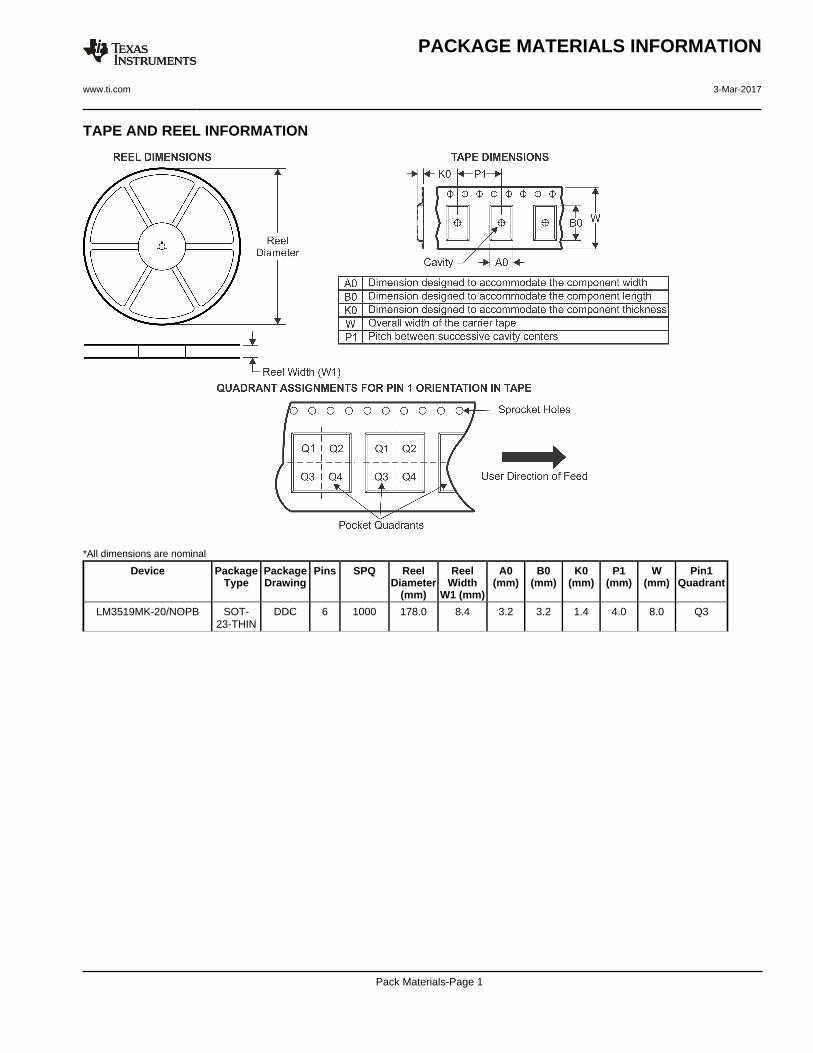
TAPE AND REEL INFORMATION
*All dimensions are nominal
Device PackageType
PackageDrawing
Pins SPQ ReelDiameter
(mm)
ReelWidth
W1 (mm)
A0(mm)
B0(mm)
K0(mm)
P1(mm)
W(mm)
Pin1Quadrant
LM3519MK-20/NOPB SOT-23-THIN
DDC 6 1000 178.0 8.4 3.2 3.2 1.4 4.0 8.0 Q3
PACKAGE MATERIALS INFORMATION
www.ti.com 3-Mar-2017
Pack Materials-Page 1

*All dimensions are nominal
Device Package Type Package Drawing Pins SPQ Length (mm) Width (mm) Height (mm)
LM3519MK-20/NOPB SOT-23-THIN DDC 6 1000 210.0 185.0 35.0
PACKAGE MATERIALS INFORMATION
www.ti.com 3-Mar-2017
Pack Materials-Page 2


IMPORTANT NOTICE
Texas Instruments Incorporated (TI) reserves the right to make corrections, enhancements, improvements and other changes to itssemiconductor products and services per JESD46, latest issue, and to discontinue any product or service per JESD48, latest issue. Buyersshould obtain the latest relevant information before placing orders and should verify that such information is current and complete.TI’s published terms of sale for semiconductor products (http://www.ti.com/sc/docs/stdterms.htm) apply to the sale of packaged integratedcircuit products that TI has qualified and released to market. Additional terms may apply to the use or sale of other types of TI products andservices.Reproduction of significant portions of TI information in TI data sheets is permissible only if reproduction is without alteration and isaccompanied by all associated warranties, conditions, limitations, and notices. TI is not responsible or liable for such reproduceddocumentation. Information of third parties may be subject to additional restrictions. Resale of TI products or services with statementsdifferent from or beyond the parameters stated by TI for that product or service voids all express and any implied warranties for theassociated TI product or service and is an unfair and deceptive business practice. TI is not responsible or liable for any such statements.Buyers and others who are developing systems that incorporate TI products (collectively, “Designers”) understand and agree that Designersremain responsible for using their independent analysis, evaluation and judgment in designing their applications and that Designers havefull and exclusive responsibility to assure the safety of Designers' applications and compliance of their applications (and of all TI productsused in or for Designers’ applications) with all applicable regulations, laws and other applicable requirements. Designer represents that, withrespect to their applications, Designer has all the necessary expertise to create and implement safeguards that (1) anticipate dangerousconsequences of failures, (2) monitor failures and their consequences, and (3) lessen the likelihood of failures that might cause harm andtake appropriate actions. Designer agrees that prior to using or distributing any applications that include TI products, Designer willthoroughly test such applications and the functionality of such TI products as used in such applications.TI’s provision of technical, application or other design advice, quality characterization, reliability data or other services or information,including, but not limited to, reference designs and materials relating to evaluation modules, (collectively, “TI Resources”) are intended toassist designers who are developing applications that incorporate TI products; by downloading, accessing or using TI Resources in anyway, Designer (individually or, if Designer is acting on behalf of a company, Designer’s company) agrees to use any particular TI Resourcesolely for this purpose and subject to the terms of this Notice.TI’s provision of TI Resources does not expand or otherwise alter TI’s applicable published warranties or warranty disclaimers for TIproducts, and no additional obligations or liabilities arise from TI providing such TI Resources. TI reserves the right to make corrections,enhancements, improvements and other changes to its TI Resources. TI has not conducted any testing other than that specificallydescribed in the published documentation for a particular TI Resource.Designer is authorized to use, copy and modify any individual TI Resource only in connection with the development of applications thatinclude the TI product(s) identified in such TI Resource. NO OTHER LICENSE, EXPRESS OR IMPLIED, BY ESTOPPEL OR OTHERWISETO ANY OTHER TI INTELLECTUAL PROPERTY RIGHT, AND NO LICENSE TO ANY TECHNOLOGY OR INTELLECTUAL PROPERTYRIGHT OF TI OR ANY THIRD PARTY IS GRANTED HEREIN, including but not limited to any patent right, copyright, mask work right, orother intellectual property right relating to any combination, machine, or process in which TI products or services are used. Informationregarding or referencing third-party products or services does not constitute a license to use such products or services, or a warranty orendorsement thereof. Use of TI Resources may require a license from a third party under the patents or other intellectual property of thethird party, or a license from TI under the patents or other intellectual property of TI.TI RESOURCES ARE PROVIDED “AS IS” AND WITH ALL FAULTS. TI DISCLAIMS ALL OTHER WARRANTIES ORREPRESENTATIONS, EXPRESS OR IMPLIED, REGARDING RESOURCES OR USE THEREOF, INCLUDING BUT NOT LIMITED TOACCURACY OR COMPLETENESS, TITLE, ANY EPIDEMIC FAILURE WARRANTY AND ANY IMPLIED WARRANTIES OFMERCHANTABILITY, FITNESS FOR A PARTICULAR PURPOSE, AND NON-INFRINGEMENT OF ANY THIRD PARTY INTELLECTUALPROPERTY RIGHTS. TI SHALL NOT BE LIABLE FOR AND SHALL NOT DEFEND OR INDEMNIFY DESIGNER AGAINST ANY CLAIM,INCLUDING BUT NOT LIMITED TO ANY INFRINGEMENT CLAIM THAT RELATES TO OR IS BASED ON ANY COMBINATION OFPRODUCTS EVEN IF DESCRIBED IN TI RESOURCES OR OTHERWISE. IN NO EVENT SHALL TI BE LIABLE FOR ANY ACTUAL,DIRECT, SPECIAL, COLLATERAL, INDIRECT, PUNITIVE, INCIDENTAL, CONSEQUENTIAL OR EXEMPLARY DAMAGES INCONNECTION WITH OR ARISING OUT OF TI RESOURCES OR USE THEREOF, AND REGARDLESS OF WHETHER TI HAS BEENADVISED OF THE POSSIBILITY OF SUCH DAMAGES.Unless TI has explicitly designated an individual product as meeting the requirements of a particular industry standard (e.g., ISO/TS 16949and ISO 26262), TI is not responsible for any failure to meet such industry standard requirements.Where TI specifically promotes products as facilitating functional safety or as compliant with industry functional safety standards, suchproducts are intended to help enable customers to design and create their own applications that meet applicable functional safety standardsand requirements. Using products in an application does not by itself establish any safety features in the application. Designers mustensure compliance with safety-related requirements and standards applicable to their applications. Designer may not use any TI products inlife-critical medical equipment unless authorized officers of the parties have executed a special contract specifically governing such use.Life-critical medical equipment is medical equipment where failure of such equipment would cause serious bodily injury or death (e.g., lifesupport, pacemakers, defibrillators, heart pumps, neurostimulators, and implantables). Such equipment includes, without limitation, allmedical devices identified by the U.S. Food and Drug Administration as Class III devices and equivalent classifications outside the U.S.TI may expressly designate certain products as completing a particular qualification (e.g., Q100, Military Grade, or Enhanced Product).Designers agree that it has the necessary expertise to select the product with the appropriate qualification designation for their applicationsand that proper product selection is at Designers’ own risk. Designers are solely responsible for compliance with all legal and regulatoryrequirements in connection with such selection.Designer will fully indemnify TI and its representatives against any damages, costs, losses, and/or liabilities arising out of Designer’s non-compliance with the terms and provisions of this Notice.
Mailing Address: Texas Instruments, Post Office Box 655303, Dallas, Texas 75265Copyright © 2017, Texas Instruments Incorporated