Embed Size (px)
Citation preview
Level measurementPoint level measurement — Vibrating switches
SITRANS LVL200
4/90 Siemens FI 01 · 2014
■ Overview
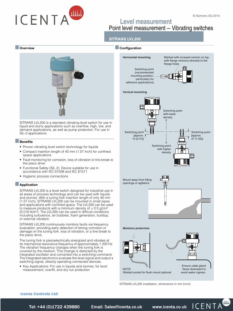
SITRANS LVL200 is a standard vibrating level switch for use in liquid and slurry applications such as overflow, high, low, and demand applications, as well as pump protection. For use in SIL-2 applications.
■ Benefits• Proven vibrating level switch technology for liquids• Compact insertion length of 40 mm (1.57 inch) for confined
space applications• Fault monitoring for corrosion, loss of vibration or line break to
the piezo drive• Functional Safety (SIL 2). Device suitable for use in
accordance with IEC 61508 and IEC 61511• Hygienic process connections
■ Application
SITRANS LVL200 is a level switch designed for industrial use inall areas of process technology and can be used with liquidsand slurries. With a tuning fork insertion length of only 40 mm(1.57 inch), SITRANS LVL200 can be mounted in small pipesand applications with confined space. The LVL200 can be usedto measure products with a minimum density of > 0.5 g/cm³(0.018 lb/in³). The LVL200 can be used in difficult conditionsincluding turbulence, air bubbles, foam generation, buildup,or external vibration.
SITRANS LVL200 continuously monitors faults via frequencyevaluation, providing early detection of strong corrosion ordamage on the tuning fork, loss of vibration, or a line break tothe piezo drive.
The tuning fork is piezoelectrically energized and vibrates atits mechanical resonance frequency of approximately 1 200 Hz. The vibration frequency changes when the tuning fork iscovered by the medium. This change is detected by theintegrated oscillator and converted into a switching command.The integrated electronics evaluate the level signal and output a switching signal, directly operating connected devices.• Key Applications: For use in liquids and slurries, for level
measurement, overfill, and dry run protection
■ Configuration
SITRANS LVL200 installation, dimensions in mm (inch)
NOTE:Welded socket for flush mount optional
Marked with screwed version on top,with flange versions directed to the flange holes
Switching point[approx. 27 (1.06)]
Mount away from fillingopenings or agitators.
Switching pointwith higher
density
Switching pointwith lower density
Switching point[approx.
13 (0.51)]
Switching point(recommended
mounting position,particularly for
adhesive applications)
Ensure cable gland faces downward to
avoid water ingress.
Moisture protection
Vertical mounting
Horizontal mounting
LVL200.fm Page 90 Friday, April 4, 2014 10:13 AM
© Siemens AG 2014
icenta Controls Ltd
Tel: +44 (0)1722 410777 Fax: +44 (0)1722 326818 e: [email protected] www.icenta.co.uk
Level measurementPoint level measurement — Vibrating switches
SITRANS LVL200
4/91Siemens FI 01 · 2014
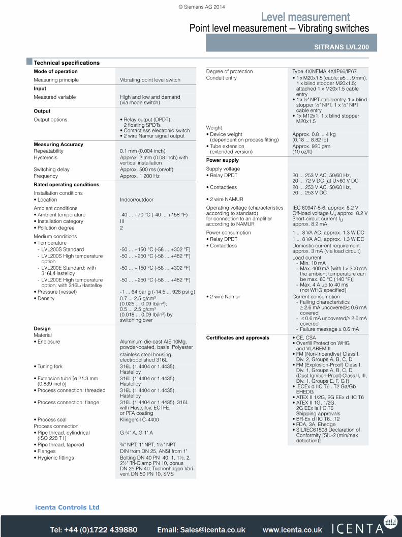
■ Technical specificationsMode of operationMeasuring principle Vibrating point level switch
Input Measured variable High and low and demand
(via mode switch)
Output Output options • Relay output (DPDT),
2 floating SPDTs• Contactless electronic switch• 2 wire Namur signal output
Measuring AccuracyRepeatability 0.1 mm (0.004 inch)Hysteresis Approx. 2 mm (0.08 inch) with
vertical installationSwitching delay Approx. 500 ms (on/off)Frequency Approx. 1 200 Hz
Rated operating conditionsInstallation conditions• Location Indoor/outdoor
Ambient conditions• Ambient temperature -40 ... +70 °C (-40 ... +158 °F)• Installation category III• Pollution degree 2
Medium conditions• Temperature
- LVL200S Standard -50 ... +150 °C (-58 ... +302 °F)- LVL200S High temperature
option -50 ... +250 °C (-58 ... +482 °F)
- LVL200E Standard: with316L/Hastelloy
-50 ... +150 °C (-58 ... +302 °F)
- LVL200E High temperatureoption: with 316L/Hastelloy
-50 ... +250 °C (-58 ... +482 °F)
• Pressure (vessel) -1 ... 64 bar g (-14.5 ... 928 psi g)• Density 0.7 ... 2.5 g/cm³
(0.025 ... 0.09 lb/in³); 0.5 ... 2.5 g/cm³ (0.018 ... 0.09 lb/in³) by switching over
DesignMaterial • Enclosure Aluminum die-cast AISi10Mg,
powder-coated, basis: Polyesterstainless steel housing, electropolished 316L
• Tuning fork 316L (1.4404 or 1.4435), Hastelloy
• Extension tube [ø 21.3 mm(0.839 inch)]
316L (1.4404 or 1.4435), Hastelloy
• Process connection: threaded 316L (1.4404 or 1.4435), Hastelloy
• Process connection: flange 316L (1.4404 or 1.4435), 316L with Hastelloy, ECTFE, or PFA coating
• Process seal Klingersil C-4400Process connection• Pipe thread, cylindrical
(ISO 228 T1)G ¾" A, G 1" A
• Pipe thread, tapered ¾" NPT, 1" NPT, 1½" NPT• Flanges DIN from DN 25, ANSI from 1"• Hygienic fittings Bolting DN 40 PN 40, 1, 1½, 2,
2½" Tri-Clamp PN 10, conus DN 25 PN 40, Tuchenhagen Vari-vent DN 50 PN 10, SMS
Degree of protection Type 4X/NEMA 4X/IP66/IP67Conduit entry • 1 x M20x1.5 (cable: ø5 ... 9 mm),
1 x blind stopper M20x1.5;attached 1 x M20x1.5 cableentry
• 1 x ½" NPT cable entry, 1 x blind stopper ½" NPT, 1 x ½" NPTcable entry
• 1x M12x1; 1 x blind stopperM20x1.5
Weight • Device weight
(dependent on process fitting) Approx. 0.8 ... 4 kg (0.18 ... 8.82 lb)
• Tube extension (extended version)
Approx. 920 g/m (10 oz/ft)
Power supplySupply voltage• Relay DPDT 20 ... 253 V AC, 50/60 Hz,
20 ... 72 V DC [at U>60 V DC• Contactless 20 ... 253 V AC, 50/60 Hz,
20 ... 253 V DC• 2 wire NAMUR
Operating voltage (characteristics according to standard) for connection to an amplifier according to NAMUR
IEC 60947-5-6, approx. 8.2 VOff-load voltage Uo approx. 8.2 VShort-circuit current IU approx. 8.2 mA
Power consumption 1 ... 8 VA AC, approx. 1.3 W DC• Relay DPDT 1 ... 8 VA AC, approx. 1.3 W DC• Contactless Domestic current requirement
approx. 3 mA (via load circuit)Load current
- Min. 10 mA- Max. 400 mA [with I > 300 mA
the ambient temperature canbe max. 60 °C (140 °F)]
- Max. 4 A up to 40 ms(not WHG specified)
• 2 wire Namur Current consumption- Falling characteristics≥ 2.6 mA uncovered/≤ 0.6 mA covered
- ≤ 0.6 mA uncovered/≥ 2.6 mA covered
- Failure message ≤ 0.6 mA
Certificates and approvals • CE, CSA• Overfill Protection WHG
and VLAREM II• FM (Non-Incendive) Class I,
Div. 2, Groups A, B, C, D• FM (Explosion-Proof) Class I,
Div. 1, Groups A, B, C, D;(Dust Ignition-Proof) Class II, III, Div. 1, Groups E, F, G1)
• IECEx d IIC T6...T2 Ga/GbEHEDG
• ATEX II 1/2G, 2G EEx d IIC T6• ATEX II 1G, 1/2G,
2G EEx ia IIC T6Shipping approvals
• BR-Ex d IIC T6...T2• FDA, 3A, Ehedge• SIL/IEC61508 Declaration of
Conformity [SIL-2 (min/maxdetection)]
LVL200.fm Page 91 Friday, April 4, 2014 10:13 AM
© Siemens AG 2014
icenta Controls Ltd
Tel: +44 (0)1722 410777 Fax: +44 (0)1722 326818 e: [email protected] www.icenta.co.uk
Level measurementPoint level measurement — Vibrating switches
SITRANS LVL200
4/92 Siemens FI 01 · 2014
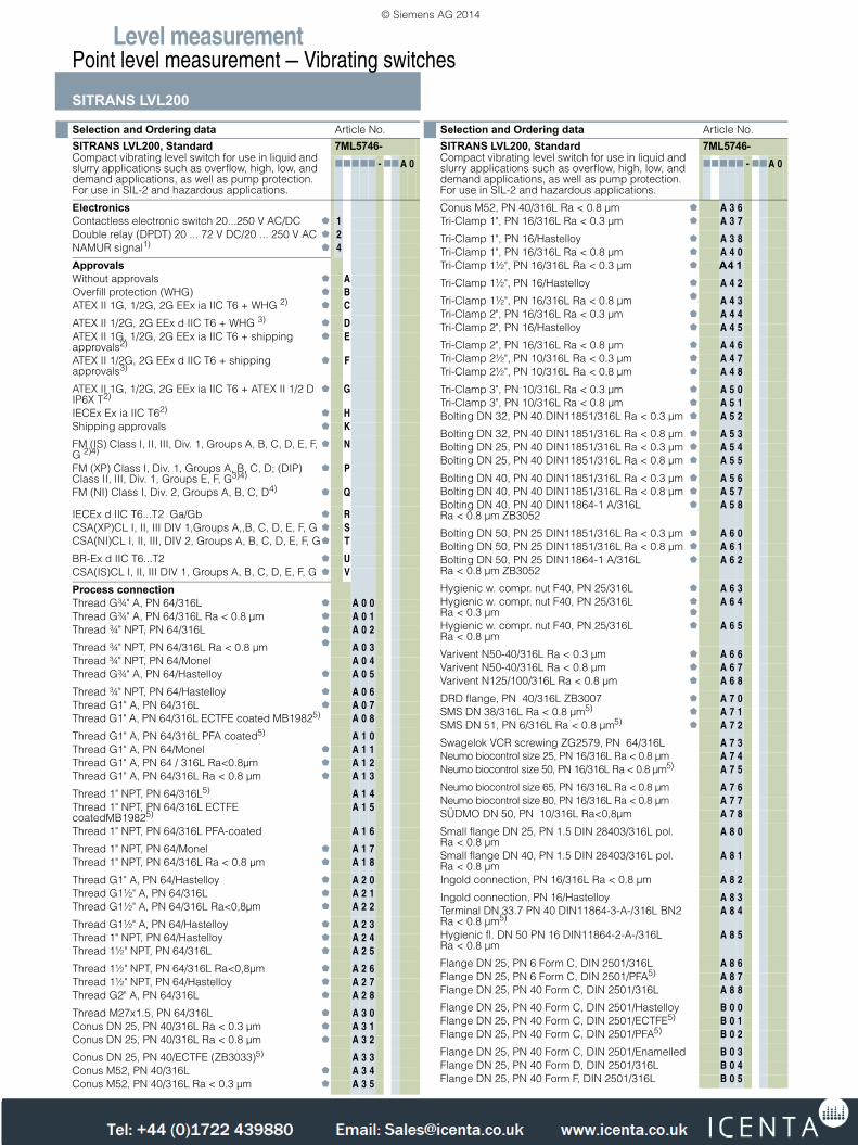
Selection and Ordering data Article No.
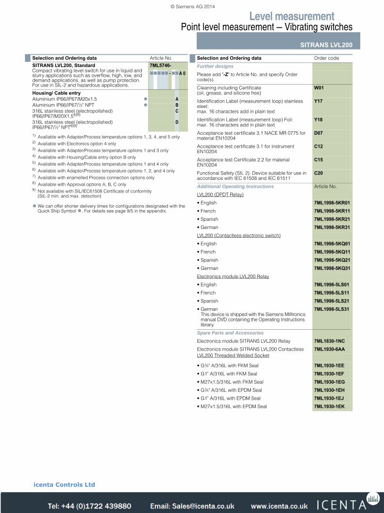
SITRANS LVL200, StandardCompact vibrating level switch for use in liquid and slurry applications such as overflow, high, low, and demand applications, as well as pump protection. For use in SIL-2 and hazardous applications.
7ML5746-77777 - 77A 0
ElectronicsContactless electronic switch 20...250 V AC/DC 1Double relay (DPDT) 20 ... 72 V DC/20 ... 250 V AC 2NAMUR signal1) 4
ApprovalsWithout approvals AOverfill protection (WHG) BATEX II 1G, 1/2G, 2G EEx ia IIC T6 + WHG 2) C
ATEX II 1/2G, 2G EEx d IIC T6 + WHG 3) DATEX II 1G, 1/2G, 2G EEx ia IIC T6 + shipping approvals2)
E
ATEX II 1/2G, 2G EEx d IIC T6 + shipping approvals3)
F
ATEX II 1G, 1/2G, 2G EEx ia IIC T6 + ATEX II 1/2 D IP6X T2)
G
IECEx Ex ia IIC T62) HShipping approvals K
FM (IS) Class I, II, III, Div. 1, Groups A, B, C, D, E, F, G 2)4)
N
FM (XP) Class I, Div. 1, Groups A, B, C, D; (DIP) Class II, III, Div. 1, Groups E, F, G3)4)
P
FM (NI) Class I, Div. 2, Groups A, B, C, D4) Q
IECEx d IIC T6...T2 Ga/Gb RCSA(XP)CL I, II, III DIV 1,Groups A,,B, C, D, E, F, G SCSA(NI)CL I, II, III, DIV 2, Groups A, B, C, D, E, F, G T
BR-Ex d IIC T6...T2 UCSA(IS)CL I, II, III DIV 1, Groups A, B, C, D, E, F, G V
Process connectionThread G¾" A, PN 64/316L A 0 0Thread G¾" A, PN 64/316L Ra < 0.8 µm A 0 1Thread ¾" NPT, PN 64/316L A 0 2
Thread ¾" NPT, PN 64/316L Ra < 0.8 µm A 0 3Thread ¾" NPT, PN 64/Monel A 0 4Thread G¾" A, PN 64/Hastelloy A 0 5
Thread ¾" NPT, PN 64/Hastelloy A 0 6Thread G1" A, PN 64/316L A 0 7Thread G1" A, PN 64/316L ECTFE coated MB19825) A 0 8
Thread G1" A, PN 64/316L PFA coated5) A 1 0Thread G1" A, PN 64/Monel A 1 1Thread G1" A, PN 64 / 316L Ra<0.8µm A 1 2Thread G1" A, PN 64/316L Ra < 0.8 µm A 1 3
Thread 1" NPT, PN 64/316L5) A 1 4Thread 1" NPT, PN 64/316L ECTFE coatedMB19825)
A 1 5
Thread 1" NPT, PN 64/316L PFA-coated A 1 6
Thread 1" NPT, PN 64/Monel A 1 7Thread 1" NPT, PN 64/316L Ra < 0.8 µm A 1 8
Thread G1" A, PN 64/Hastelloy A 2 0Thread G1½" A, PN 64/316L A 2 1Thread G1½" A, PN 64/316L Ra<0,8µm A 2 2
Thread G1½" A, PN 64/Hastelloy A 2 3Thread 1" NPT, PN 64/Hastelloy A 2 4Thread 1½" NPT, PN 64/316L A 2 5
Thread 1½" NPT, PN 64/316L Ra<0,8µm A 2 6Thread 1½" NPT, PN 64/Hastelloy A 2 7Thread G2" A, PN 64/316L A 2 8
Thread M27x1.5, PN 64/316L A 3 0Conus DN 25, PN 40/316L Ra < 0.3 µm A 3 1Conus DN 25, PN 40/316L Ra < 0.8 µm A 3 2
Conus DN 25, PN 40/ECTFE (ZB3033)5) A 3 3Conus M52, PN 40/316L A 3 4Conus M52, PN 40/316L Ra < 0.3 µm A 3 5
Conus M52, PN 40/316L Ra < 0.8 µm A 3 6Tri-Clamp 1", PN 16/316L Ra < 0.3 µm A 3 7
Tri-Clamp 1", PN 16/Hastelloy A 3 8Tri-Clamp 1", PN 16/316L Ra < 0.8 µm A 4 0Tri-Clamp 1½", PN 16/316L Ra < 0.3 µm A4 1Tri-Clamp 1½", PN 16/Hastelloy A 4 2
Tri-Clamp 1½", PN 16/316L Ra < 0.8 µm A 4 3Tri-Clamp 2", PN 16/316L Ra < 0.3 µm A 4 4Tri-Clamp 2", PN 16/Hastelloy A 4 5
Tri-Clamp 2", PN 16/316L Ra < 0.8 µm A 4 6Tri-Clamp 2½", PN 10/316L Ra < 0.3 µm A 4 7Tri-Clamp 2½", PN 10/316L Ra < 0.8 µm A 4 8
Tri-Clamp 3", PN 10/316L Ra < 0.3 µm A 5 0Tri-Clamp 3", PN 10/316L Ra < 0.8 µm A 5 1Bolting DN 32, PN 40 DIN11851/316L Ra < 0.3 µm A 5 2
Bolting DN 32, PN 40 DIN11851/316L Ra < 0.8 µm A 5 3Bolting DN 25, PN 40 DIN11851/316L Ra < 0.3 µm A 5 4Bolting DN 25, PN 40 DIN11851/316L Ra < 0.8 µm A 5 5
Bolting DN 40, PN 40 DIN11851/316L Ra < 0.3 µm A 5 6Bolting DN 40, PN 40 DIN11851/316L Ra < 0.8 µm A 5 7Bolting DN 40, PN 40 DIN11864-1 A/316L Ra < 0.8 µm ZB3052
A 5 8
Bolting DN 50, PN 25 DIN11851/316L Ra < 0.3 µm A 6 0Bolting DN 50, PN 25 DIN11851/316L Ra < 0.8 µm A 6 1Bolting DN 50, PN 25 DIN11864-1 A/316L Ra < 0.8 µm ZB3052
A 6 2
Hygienic w. compr. nut F40, PN 25/316L A 6 3Hygienic w. compr. nut F40, PN 25/316L Ra < 0.3 µm
A 6 4
Hygienic w. compr. nut F40, PN 25/316L Ra < 0.8 µm
A 6 5
Varivent N50-40/316L Ra < 0.3 µm A 6 6Varivent N50-40/316L Ra < 0.8 µm A 6 7Varivent N125/100/316L Ra < 0.8 µm A 6 8
DRD flange, PN 40/316L ZB3007 A 7 0SMS DN 38/316L Ra < 0.8 µm5) A 7 1SMS DN 51, PN 6/316L Ra < 0.8 µm5) A 7 2
Swagelok VCR screwing ZG2579, PN 64/316L A 7 3Neumo biocontrol size 25, PN 16/316L Ra < 0.8 µm A 7 4Neumo biocontrol size 50, PN 16/316L Ra < 0.8 µm5) A 7 5
Neumo biocontrol size 65, PN 16/316L Ra < 0.8 µm A 7 6Neumo biocontrol size 80, PN 16/316L Ra < 0.8 µm A 7 7SÜDMO DN 50, PN 10/316L Ra<0,8µm A 7 8
Small flange DN 25, PN 1.5 DIN 28403/316L pol.Ra < 0.8 µm
A 8 0
Small flange DN 40, PN 1.5 DIN 28403/316L pol.Ra < 0.8 µm
A 8 1
Ingold connection, PN 16/316L Ra < 0.8 µm A 8 2
Ingold connection, PN 16/Hastelloy A 8 3Terminal DN 33.7 PN 40 DIN11864-3-A-/316L BN2 Ra < 0.8 µm5)
A 8 4
Hygienic fl. DN 50 PN 16 DIN11864-2-A-/316L Ra < 0.8 µm
A 8 5
Flange DN 25, PN 6 Form C, DIN 2501/316L A 8 6Flange DN 25, PN 6 Form C, DIN 2501/PFA5) A 8 7Flange DN 25, PN 40 Form C, DIN 2501/316L A 8 8
Flange DN 25, PN 40 Form C, DIN 2501/Hastelloy B 0 0Flange DN 25, PN 40 Form C, DIN 2501/ECTFE5) B 0 1Flange DN 25, PN 40 Form C, DIN 2501/PFA5) B 0 2
Flange DN 25, PN 40 Form C, DIN 2501/Enamelled B 0 3Flange DN 25, PN 40 Form D, DIN 2501/316L B 0 4Flange DN 25, PN 40 Form F, DIN 2501/316L B 0 5
Selection and Ordering data Article No.
SITRANS LVL200, StandardCompact vibrating level switch for use in liquid and slurry applications such as overflow, high, low, and demand applications, as well as pump protection. For use in SIL-2 and hazardous applications.
7ML5746-77777 - 77A 0
LVL200.fm Page 92 Friday, April 4, 2014 10:13 AM
© Siemens AG 2014
Tel: +44 (0)1722 410777 Fax: +44 (0)1722 326818 e: [email protected] www.icenta.co.uk
Level measurementPoint level measurement — Vibrating switches
SITRANS LVL200
4/93Siemens FI 01 · 2014
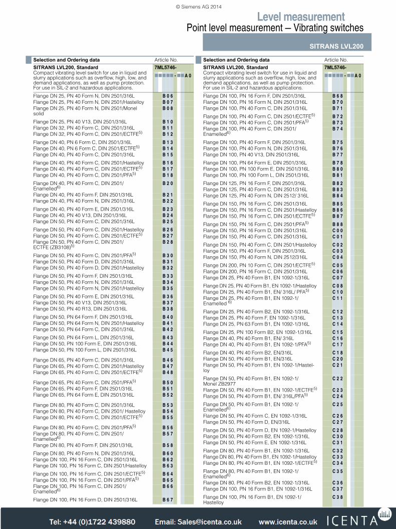
Flange DN 25, PN 40 Form N, DIN 2501/316L B 0 6Flange DN 25, PN 40 Form N, DIN 2501/Hastelloy B 0 7Flange DN 25, PN 40 Form N, DIN 2501/Monel solid
B 0 8
Flange DN 25, PN 40 V13, DIN 2501/316L B 1 0Flange DN 32, PN 40 Form C, DIN 2501/316L B 1 1Flange DN 32, PN 40 Form C, DIN 2501/ECTFE5) B 1 2
Flange DN 40, PN 6 Form C, DIN 2501/316L B 1 3Flange DN 40, PN 6 Form C, DIN 2501/ECTFE5) B 1 4Flange DN 40, PN 40 Form C, DIN 2501/316L B 1 5
Flange DN 40, PN 40 Form C, DIN 2501/Hastelloy B 1 6Flange DN 40, PN 40 Form C, DIN 2501/ECTFE5) B 1 7Flange DN 40, PN 40 Form C, DIN 2501/PFA5) B 1 8
Flange DN 40, PN 40 Form C, DIN 2501/Enamelled6)
B 2 0
Flange DN 40, PN 40 Form F, DIN 2501/316L B 2 1Flange DN 40, PN 40 Form N, DIN 2501/316L B 2 2
Flange DN 40, PN 40 Form E, DIN 2501/316L B 2 3Flange DN 40, PN 40 V13, DIN 2501/316L B 2 4Flange DN 50, PN 40 Form C, DIN 2501/316L B 2 5
Flange DN 50, PN 40 Form C, DIN 2501/Hastelloy B 2 6Flange DN 50, PN 40 Form C, DIN 2501/ECTFE5) B 2 7Flange DN 50, PN 40 Form C, DIN 2501/ECTFE (ZB3108)5)
B 2 8
Flange DN 50, PN 40 Form C, DIN 2501/PFA5) B 3 0Flange DN 50, PN 40 Form D, DIN 2501/316L B 3 1Flange DN 50, PN 40 Form D, DIN 2501/Hastelloy B 3 2
Flange DN 50, PN 40 Form F, DIN 2501/316L B 3 3Flange DN 50, PN 40 Form N, DIN 2501/316L B 3 4Flange DN 50, PN 40 Form N, DIN 2501/Hastelloy B 3 5
Flange DN 50, PN 40 Form E, DIN 2501/316L B 3 6Flange DN 50, PN 40 V13, DIN 2501/316L B 3 7Flange DN 50, PN 40 R13, DIN 2501/316L B 3 8
Flange DN 50, PN 64 Form F, DIN 2501/316L B 4 0Flange DN 50, PN 64 Form N, DIN 2501/Hastelloy B 4 1Flange DN 50, PN 64 Form C, DIN 2501/316L B 4 2
Flange DN 50, PN 64 Form L, DIN 2501/316L B 4 3Flange DN 50, PN 100 Form E, DIN 2501/316L B 4 4Flange DN 50, PN 100 Form L, DIN 2501/316L B 4 5
Flange DN 65, PN 40 Form C, DIN 2501/316L B 4 6Flange DN 65, PN 40 Form C, DIN 2501/Hastelloy B 4 7Flange DN 65, PN 40 Form C, DIN 2501/ECTFE5) B 4 8
Flange DN 65, PN 40 Form C, DIN 2501/PFA5) B 5 0Flange DN 65, PN 40 Form F, DIN 2501/316L B 5 1Flange DN 65, PN 64 Form E, DIN 2501/316L B 5 2
Flange DN 80, PN 40 Form C, DIN 2501/316L B 5 3Flange DN 80, PN 40 Form C, DIN 2501/ Hastelloy B 5 4Flange DN 80, PN 40 Form C, DIN 2501/ECTFE5) B 5 5
Flange DN 80, PN 40 Form C, DIN 2501/PFA5) B 5 6Flange DN 80, PN 40 Form C, DIN 2501/Enamelled6)
B 5 7
Flange DN 80, PN 40 Form F, DIN 2501/316L B 5 8
Flange DN 80, PN 40 Form N, DIN 2501/316L B 6 0Flange DN 100, PN 16 Form C, DIN 2501/316L B 6 2Flange DN 100, PN 16 Form C, DIN 2501/Hastelloy B 6 3
Flange DN 100, PN 16 Form C, DIN 2501/ECTFE5) B 6 4Flange DN 100, PN 16 Form C, DIN 2501/PFA5) B 6 5Flange DN 100, PN 16 Form C, DIN 2501/Enamelled6)
B 6 6
Flange DN 100, PN 16 Form D, DIN 2501/316L B 6 7
Selection and Ordering data Article No.
SITRANS LVL200, StandardCompact vibrating level switch for use in liquid and slurry applications such as overflow, high, low, and demand applications, as well as pump protection. For use in SIL-2 and hazardous applications.
7ML5746-77777 - 77A 0
Flange DN 100, PN 16 Form F, DIN 2501/316L B 6 8Flange DN 100, PN 16 Form N, DIN 2501/316L B 7 0Flange DN 100, PN 40 Form C, DIN 2501/316L B 7 1
Flange DN 100, PN 40 Form C, DIN 2501/ECTFE5) B 7 2Flange DN 100, PN 40 Form C, DIN 2501/PFA5) B 7 3Flange DN 100, PN 40 Form C, DIN 2501/Enamelled6)
B 7 4
Flange DN 100, PN 40 Form F, DIN 2501/316L B 7 5Flange DN 100, PN 40 Form N, DIN 2501/316L B 7 6Flange DN 100, PN 40 V13, DIN 2501/316L B 7 7
Flange DN 100, PN 64 Form E, DIN 2501/316L B 7 8Flange DN 100, PN 100 Form E, DIN 2501/316L B 8 0Flange DN 100, PN 100 Form L, DIN 2501/316L B 8 1
Flange DN 125, PN 16 Form F, DIN 2501/316L B 8 2Flange DN 125, PN 40 Form C, DIN 2501/316L B 8 3Flange DN 125, PN 40 Form N, DIN 2512/ 316L B 8 4
Flange DN 150, PN 16 Form C, DIN 2501/316L B 8 5Flange DN 150, PN 16 Form C, DIN 2501/Hastelloy B 8 6Flange DN 150, PN 16 Form C, DIN 2501/ECTFE5) B 8 7
Flange DN 150, PN 16 Form C, DIN 2501/PFA5) B 8 8Flange DN 150, PN 16 Form D, DIN 2501/316L C 0 0Flange DN 150, PN 40 Form C, DIN 2501/316L C 0 1
Flange DN 150, PN 40 Form C, DIN 2501/Hastelloy C 0 2Flange DN 150, PN 40 Form F, DIN 2501/316L C 0 3Flange DN 150, PN 40 Form N, DIN 2512/316L C 0 4
Flange DN 200, PN 10 Form C, DIN 2501/ECTFE5) C 0 5Flange DN 200, PN 16 Form C, DIN 2501/316L C 0 6Flange DN 25, PN 40 Form B1, EN 1092-1/316L C 0 7
Flange DN 25, PN 40 Form B1, EN 1092-1/Hastelloy C 0 8Flange DN 25, PN 40 Form B1, EN/ 316L/ PFA5) C 1 0Flange DN 25, PN 40 Form B1, EN 1092-1/Enamelled 6)
C 1 1
Flange DN 25, PN 40 Form B2, EN 1092-1/316L C 1 2Flange DN 25, PN 40 Form F, EN 1092-1/316L C 1 3Flange DN 25, PN 63 Form B1, EN 1092-1/316L C 1 4
Flange DN 25, PN 100 Form B2, EN 1092-1/316L C 1 5Flange DN 40, PN 40 Form B1, EN/ 316L C 1 6Flange DN 40, PN 40 Form B1, EN 1092-1/PFA5) C 1 7
Flange DN 40, PN 40 Form B2, EN/316L C 1 8Flange DN 50, PN 40 Form B1, EN/316L C 2 0Flange DN 50, PN 40 Form B1, EN 1092-1/Hastel-loy
C 2 1
Flange DN 50, PN 40 Form B1, EN 1092-1/Monel ZB2977
C 2 2
Flange DN 50, PN 40 Form B1, EN 1092-1/ECTFE5) C 2 3Flange DN 50, PN 40 Form B1, EN/ 316L/PFA5) C 2 4
Flange DN 50, PN 40 Form B1, EN 1092-1/Enamelled6)
C 2 5
Flange DN 50, PN 40 Form C, EN 1092-1/316L C 2 6Flange DN 50, PN 40 Form D, EN/316L C 2 7
Flange DN 50, PN 40 Form D, EN 1092-1/Hastelloy C 2 8Flange DN 50, PN 40 Form B2, EN 1092-1/316L C 3 0Flange DN 50, PN 40 Form E, EN 1092-1/316L C 3 1
Flange DN 80, PN 40 Form B1, EN 1092-1/316L C 3 2Flange DN 80, PN 40 Form B1, EN 1092-1/Hastelloy C 3 3Flange DN 80, PN 40 Form B1, EN 1092-1/ECTFE5) C 3 4
Flange DN 80, PN 40 Form B1, EN 1092-1/Enamelled6)
C 3 5
Flange DN 80, PN 40 Form B2, EN 1092-1/316L C 3 6Flange DN 100, PN 16 Form B1, EN 1092-1/316L C 3 7
Flange DN 100, PN 16 Form B1, EN 1092-1/Hastelloy
C 3 8
Selection and Ordering data Article No.
SITRANS LVL200, StandardCompact vibrating level switch for use in liquid and slurry applications such as overflow, high, low, and demand applications, as well as pump protection. For use in SIL-2 and hazardous applications.
7ML5746-77777 - 77A 0
LVL200.fm Page 93 Friday, April 4, 2014 10:13 AM
© Siemens AG 2014
Tel: +44 (0)1722 410777 Fax: +44 (0)1722 326818 e: [email protected] www.icenta.co.uk
Level measurementPoint level measurement — Vibrating switches
SITRANS LVL200
4/94 Siemens FI 01 · 2014
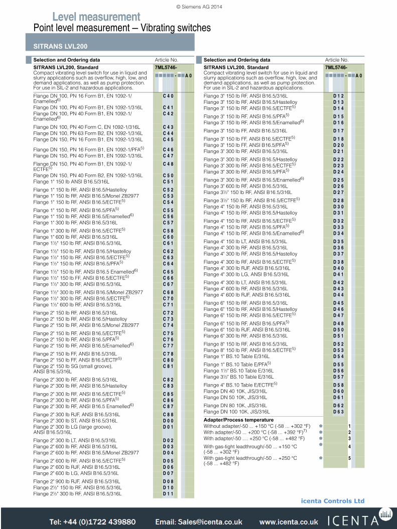
Flange DN 100, PN 16 Form B1, EN 1092-1/Enamelled6)
C 4 0
Flange DN 100, PN 40 Form B1, EN 1092-1/316L C 4 1Flange DN 100, PN 40 Form B1, EN 1092-1/Enamelled6)
C 4 2
Flange DN 100, PN 40 Form C, EN 1092-1/316L C 4 3Flange DN 100, PN 63 Form B2, EN 1092-1/316L C 4 4Flange DN 150, PN 16 Form B1, EN 1092-1/316L C 4 5
Flange DN 150, PN 16 Form B1, EN 1092-1/PFA5) C 4 6Flange DN 150, PN 40 Form B1, EN 1092-1/316L C 4 7
Flange DN 150, PN 40 Form B1, EN 1092-1/ECTFE5)
C 4 8
Flange DN 150, PN 40 Form B2, EN 1092-1/316L C 5 0Flange 1" 150 lb ANSI B16.5/316L C 5 1
Flange 1" 150 lb RF, ANSI B16.5/Hastelloy C 5 2Flange 1" 150 lb RF, ANSI B16.5/Monel ZB2977 C 5 3Flange 1" 150 lb RF, ANSI B16.5/ECTFE5) C 5 4
Flange 1" 150 lb RF, ANSI B16.5/PFA5) C 5 5Flange 1" 150 lb RF, ANSI B16.5/Enamelled6) C 5 6Flange 1" 300 lb RF, ANSI B16.5/316L C 5 7
Flange 1" 300 lb RF, ANSI B16.5/ECTFE5) C 5 8Flange 1" 600 lb RF, ANSI B16.5/316L C 6 0Flange 1½" 150 lb RF, ANSI B16.5/316L C 6 1
Flange 1½" 150 lb RF, ANSI B16.5/Hastelloy C 6 2Flange 1½" 150 lb RF, ANSI B16.5/ECTFE5) C 6 3Flange 1½" 150 lb RF, ANSI B16.5/PFA5) C 6 4
Flange 1½" 150 lb RF, ANSI B16.5 Enamelled6) C 6 5Flange 1½" 150 lb FF, ANSI B16.5/ECTFE5) C 6 6Flange 1½" 300 lb RF, ANSI B16.5/316L C 6 7
Flange 1½" 300 lb RF, ANSI B16.5/Monel ZB2977 C 6 8Flange 1½" 300 lb RF, ANSI B16.5/ECTFE6) C 7 0Flange 1½" 600 lb RF, ANSI B16.5/316L C 7 1
Flange 2" 150 lb RF, ANSI B16.5/316L C 7 2Flange 2" 150 lb RF, ANSI B16.5/Hastelloy C 7 3Flange 2" 150 lb RF, ANSI B16.5/Monel ZB2977 C 7 4
Flange 2" 150 lb RF, ANSI B16.5/ECTFE5) C 7 5Flange 2" 150 lb RF, ANSI B16.5/PFA5) C 7 6Flange 2" 150 lb RF, ANSI B16.5/Enamelled6) C 7 7
Flange 2" 150 lb FF, ANSI B16.5/316L C 7 8Flange 2" 150 lb FF, ANSI B16.5/ECTF5) C 8 0Flange 2" 150 lb SG (small groove), ANSI B16.5/316L
C 8 1
Flange 2" 300 lb RF, ANSI B16.5/316L C 8 2Flange 2" 300 lb RF, ANSI B16.5/Hastelloy C 8 3
Flange 2" 300 lb RF, ANSI B16.5/ECTFE5) C 8 5Flange 2" 300 lb RF, ANSI B16.5/PFA5) C 8 6Flange 2" 300 lb RF, ANSI B16.5 Enamelled6) C 8 7
Flange 2" 300 lb RJF, ANSI B16.5/316L C 8 8Flange 2" 300 lb ST, ANSI B16.5/316L D 0 0Flange 2" 300 lb LG (large groove), ANSI B16.5/316L
D 0 1
Flange 2" 300 lb LT, ANSI B16.5/316L D 0 2Flange 2" 600 lb RF, ANSI B16.5/316L D 0 3Flange 2" 600 lb RF, ANSI B16.5/Monel ZB2977 D 0 4
Flange 2" 600 lb RF, ANSI B16.5/ECTFE5) D 0 5Flange 2" 600 lb RJF, ANSI B16.5/316L D 0 6Flange 2" 600 lb LG, ANSI B16.5/316L D 0 7
Flange 2" 900 lb RJF, ANSI B16.5/316L D 0 8Flange 2½" 150 lb RF, ANSI B16.5/316L D 1 0Flange 2½" 300 lb RF, ANSI B16.5/316L D 1 1
Selection and Ordering data Article No.
SITRANS LVL200, StandardCompact vibrating level switch for use in liquid and slurry applications such as overflow, high, low, and demand applications, as well as pump protection. For use in SIL-2 and hazardous applications.
7ML5746-77777 - 77A 0
Flange 3" 150 lb RF, ANSI B16.5/316L D 1 2Flange 3" 150 lb RF, ANSI B16.5/Hastelloy D 1 3Flange 3" 150 lb RF, ANSI B16.5/ECTFE5) D 1 4
Flange 3" 150 lb RF, ANSI B16.5/PFA5) D 1 5Flange 3" 150 lb RF, ANSI B16.5/Enamelled6) D 1 6
Flange 3" 150 lb FF, ANSI B16.5/316L D 1 7
Flange 3" 150 lb FF, ANSI B16.5/ECTFE5) D 1 8Flange 3" 150 lb FF, ANSI B16.5/PFA5) D 2 0Flange 3" 300 lb RF, ANSI B16.5/316L D 2 1
Flange 3" 300 lb RF, ANSI B16.5/Hastelloy D 2 2Flange 3" 300 lb RF, ANSI B16.5/ECTFE5) D 2 3Flange 3" 300 lb RF, ANSI B16.5/PFA5) D 2 4
Flange 3" 300 lb RF, ANSI B16.5/Enamelled6) D 2 5Flange 3" 600 lb RF, ANSI B16.5/316L D 2 6Flange 3½" 150 lb RF, ANSI B16.5/316L D 2 7
Flange 3½" 150 lb RF, ANSI B16.5/ECTFE5) D 2 8Flange 4" 150 lb RF, ANSI B16.5/316L D 3 0Flange 4" 150 lb RF, ANSI B16.5/Hastelloy D 3 1
Flange 4" 150 lb RF, ANSI B16.5/ECTFE5) D 3 2Flange 4" 150 lb RF, ANSI B16.5/PFA5) D 3 3Flange 4" 150 lb RF, ANSI B16.5/Enamelled6) D 3 4
Flange 4" 150 lb LT, ANSI B16.5/316L D 3 5Flange 4" 300 lb RF, ANSI B16.5/316L D 3 6Flange 4" 300 lb RF, ANSI B16.5/Hastelloy D 3 7
Flange 4" 300 lb RF, ANSI B16.5/ECTFE5) D 3 8Flange 4" 300 lb RJF, ANSI B16.5/316L D 4 0Flange 4" 300 lb LG, ANSI B16.5/316L D 4 1
Flange 4" 300 lb LT, ANSI B16.5/316L D 4 2Flange 4" 600 lb RF, ANSI B16.5/316L D 4 3Flange 4" 600 lb RJF, ANSI B16.5/316L D 4 4
Flange 6" 150 lb RF, ANSI B16.5/316L D 4 5Flange 6" 150 lb RF, ANSI B16.5/Hastelloy D 4 6Flange 6" 150 lb RF, ANSI B16.5/ECTFE5) D 4 7
Flange 6" 150 lb RF, ANSI B16.5/PFA5) D 4 8Flange 6" 150 lb RJF, ANSI B16.5/316L D 5 0Flange 6" 300 lb RF, ANSI B16.5/316L D 5 1
Flange 8" 150 lb RF, ANSI B16.5/316L D 5 2Flange 8" 150 lb RF, ANSI B16.5/ECTFE5) D 5 3Flange 1" BS.10 Table E/316L D 5 4
Flange 1" BS.10 Table E/PFA5) D 5 5Flange 1½" BS.10 Table E/316L D 5 6Flange 3½" BS.10 Table E/316L D 5 7
Flange 4" BS.10 Table E/ECTFE5) D 5 8Flange DN 40 10K, JIS/316L D 6 0Flange DN 50 10K, JIS/316L D 6 1
Flange DN 80 10K, JIS/316L D 6 2Flange DN 100 10K, JIS/316L D 6 3
Adapter/Process temperatureWithout adapter/-50 ... +150 °C (-58 ... +302 °F) 1With adapter/-50 ... +200 °C (-58 ... +392 °F)7) 2With adapter/-50 .... +250 °C (-58 ... +482 °F) 3
With gas-tight leadthrough/-50 ... +150 °C (-58 ... +302 °F)
4
With gas-tight leadthrough/-50 ... +250 °C (-58 ... +482 °F)
5
Selection and Ordering data Article No.
SITRANS LVL200, StandardCompact vibrating level switch for use in liquid and slurry applications such as overflow, high, low, and demand applications, as well as pump protection. For use in SIL-2 and hazardous applications.
7ML5746-77777 - 77A 0
LVL200.fm Page 94 Friday, April 4, 2014 10:13 AM
© Siemens AG 2014
icenta Controls Ltd
Tel: +44 (0)1722 410777 Fax: +44 (0)1722 326818 e: [email protected] www.icenta.co.uk
Level measurementPoint level measurement — Vibrating switches
SITRANS LVL200
4/95Siemens FI 01 · 2014
We can offer shorter delivery times for configurations designated with theQuick Ship Symbol . For details see page 9/5 in the appendix.
Housing/ Cable entryAluminium IP66/IP67/M20x1.5 AAluminium IP66/IP67/½" NPT B316L stainless steel (electropolished) IP66/IP67/M20X1.58)9)
C
316L stainless steel (electropolished) IP66/IP67/½" NPT8)9)
D
1) Available with Adapter/Process temperature options 1, 3, 4, and 5 only2) Available with Electronics option 4 only3) Available with Adapter/Process temperature options 1 and 3 only4) Available with Housing/Cable entry option B only5) Available with Adapter/Process temperature options 1 and 4 only6) Available with Adapter/Process temperature options 1, 2, and 4 only7) Available with enamelled Process connection options only8) Available with Approval options A, B, C only9) Not available with SIL/IEC61508 Certificate of conformity
(SIL-2 min. and max. detection)
Selection and Ordering data Article No.
SITRANS LVL200, StandardCompact vibrating level switch for use in liquid and slurry applications such as overflow, high, low, and demand applications, as well as pump protection. For use in SIL-2 and hazardous applications.
7ML5746-77777 - 77A 0
Selection and Ordering data Order code
Further designsPlease add "-Z" to Article No. and specify Order code(s).
Cleaning including Certificate (oil, grease, and silicone free)
W01
Identification Label (measurement loop) stainless steel:max. 16 characters add in plain text
Y17
Identification Label (measurement loop) Foil: max. 16 characters add in plain text
Y18
Acceptance test certificate 3.1 NACE MR 0775 for material EN10204
D07
Acceptance test certificate 3.1 for instrument EN10204
C12
Acceptance test Certificate 2.2 for material EN10204
C15
Functional Safety (SIL 2). Device suitable for use in accordance with IEC 61508 and IEC 61511
C20
Additional Operating Instructions Article No.
LVL200 (DPDT Relay)
• English 7ML1998-5KR01• French 7ML1998-5KR11• Spanish 7ML1998-5KR21• German 7ML1998-5KR31LVL200 (Contactless electronic switch)
• English 7ML1998-5KQ01• French 7ML1998-5KQ11• Spanish 7ML1998-5KQ21• German 7ML1998-5KQ31Electronics module LVL200 Relay
• English 7ML1998-5LS01• French 7ML1998-5LS11• Spanish 7ML1998-5LS21• German
This device is shipped with the Siemens Milltronics manual DVD containing the Operating Instructions library.
7ML1998-5LS31
Spare Parts and AccessoriesElectronics module SITRANS LVL200 Relay 7ML1830-1NCElectronics module SITRANS LVL200 Contactless 7ML1930-6AALVL200 Threaded Welded Socket
• G¾" A/316L with FKM Seal 7ML1930-1EE• G1" A/316L with FKM Seal 7ML1930-1EF• M27x1.5/316L with FKM Seal 7ML1930-1EG• G¾" A/316L with EPDM Seal 7ML1930-1EH• G1" A/316L with EPDM Seal 7ML1930-1EJ• M27x1.5/316L with EPDM Seal 7ML1930-1EK
LVL200.fm Page 95 Friday, April 4, 2014 10:13 AM
© Siemens AG 2014
icenta Controls Ltd
Tel: +44 (0)1722 410777 Fax: +44 (0)1722 326818 e: [email protected] www.icenta.co.uk

Level measurementPoint level measurement — Vibrating switches
SITRANS LVL200
4/96 Siemens FI 01 · 2014
Selection and Ordering data Article No.
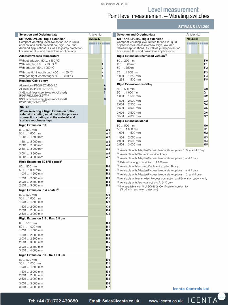
SITRANS LVL200, Rigid extensionCompact vibrating level switch for use in liquid applications such as overflow, high, low, and demand applications, as well as pump protection. For use in SIL-2 and hazardous applications.
7ML5747-77777 - 7777
ElectronicsContactless electronic switch 20...250 V AC/DC 1Double relay (DPDT) 20 ... 72 V DC/20 ... 250 V AC 2NAMUR signal1) 4
ApprovalsWithout approvals AOverfill protection (WHG) BATEX II 1G, 1/2G, 2G EEx ia IIC T6 + WHG2) C
ATEX II 1/2G, 2G EEx d IIC T6 + WHG3)4) DATEX II 1G, 1/2G, 2G EEx ia IIC T6 + shipping approvals2)
E
ATEX II 1/2G, 2G EEx d IIC T6 + shipping approvals3)4)
F
ATEX II 1G, 1/2G, 2G EEx ia IIC T6 + ATEX II 1/2D IP6X T2)
G
IECEx Ex ia IIC T62) HShipping approvals K
FM (IS) Class I, II, III, Div. 1, Groups A, B, C, D, E, F, G 2)5) NFM (XP) Class I, Div. 1, Groups A, B, C, D; (DIP) Class II, III, Div. 1, Groups E, F, G3)4)5)
P
FM (NI) Class I, Div. 2, Groups A, B, C, D5) QIECEx d IIC T6...T2 Ga/Gb4) RCSA(XP)CL I,II,III Div. 1,Groups A, B, C, D, E, F, G...T2 4)
Ga/Gb
S
CSA(NI)CL I,II,III, Div. 2,Groups A, B, C, D, E, F, G TBR-Ex d IIC T6...T2 UCSA(IS)CL I, II, III Div. 1, Groups A, B, C, D, E, F, G V
Process connectionThread G¾" A, PN 64/316L A 0 0Thread G¾" A, PN 64/316L Ra < 0.8 µm A 0 1Thread ¾" NPT, PN 64/316L A 0 2
Thread ¾" NPT, PN 64/316L Ra < 0.8 µm A 0 3Thread ¾" NPT, PN 64/Monel A 0 4Thread G¾" A, PN 64/Hastelloy A 0 5
Thread ¾" NPT, PN 64/Hastelloy A 0 6Thread G1" A, PN 64/316L A 0 7Thread G1" A, PN 64/316L ECTFE coated MB19826)
A 0 8
Thread G1" A, PN 64/316L PFA coated6) A 1 0Thread G1" A, PN 64/Monel A 1 1Thread G1" A, PN 64/316L Ra < 0.8 µm A 1 3
Thread 1" NPT, PN 64/316L A 1 4Thread 1" NPT, PN 64/316L ECTFE coated MB19826) A 1 5Thread 1" NPT, PN 64/316L PFA coated6) A 1 6
Thread 1" NPT, PN 64/Monel A 1 7Thread 1" NPT, PN 64/316L Ra < 0.8 µm A 1 8Thread G1" A, PN 64/Hastelloy A 2 0
Thread G1½" A, PN 64/316L A 2 1Thread G1½" A, PN 64/316L Ra <0.8 µm A 2 2Thread G1½" A, PN 64/Hastelloy A 2 3
Thread 1" NPT, PN 64/Hastelloy A 2 4Thread 1½" NPT, PN 64/316L A 2 5Thread 1½" NPT, PN 64/316L Ra< 0.8 µm A 2 6
Thread 1½" NPT, PN 64/Hastelloy A 2 7Thread G2" A, PN 64/316L A 2 8Thread M27x1.5 PN 64/316L A 3 0
Cyl. socket/316Ti/1.4581 ECTFE coated ZB29846) A 3 1Conus DN 25 PN 40/316L Ra < 0.3 µm A 3 2Conus DN 25 PN 40/316L Ra < 0.8 µm. A 3 3
Conus DN 25 PN 40/ECTFE (ZB3033)6) A 3 4Conus M52 PN 40/316L A 3 5Conus M52 PN 40/316L Ra < 0.3 µm A 3 6
Conus M52 PN 40/316L Ra < 0.8 µm A 3 7Tri-Clamp 1" PN 16/316L Ra < 0.3 µm A 3 8Tri-Clamp 1" PN 16/Hastelloy A 4 0
Tri-Clamp 1" PN 16/316L Ra < 0.8 µm A 4 1Tri-Clamp 1½" PN 16/316L Ra < 0.3 µm A 4 2Tri-Clamp 1½" PN 16/Hastelloy A 4 3
Tri-Clamp 1½" PN 16/316L Ra < 0.8 µm A 4 4Tri-Clamp 2" PN 16/316L Ra < 0.3 µm A 4 5Tri-Clamp 2" PN 16/Hastelloy A 4 6
Tri-Clamp 2" PN 16/316L Ra < 0.8 µm A 4 7Tri-Clamp 2½" PN 10/316L Ra < 0.3 µm A 4 8Tri-Clamp 2½" PN 10/316L Ra < 0.8 µm A 5 0
Tri-Clamp 3" PN 10/316L Ra < 0.3 µm A 5 1Tri-Clamp 3" PN 10/316L Ra < 0.8 µm A 5 2Bolting DN 32 PN 40 DIN11851/316L Ra < 0.3 µm A 5 3
Bolting DN 32 PN 40 DIN11851/316L Ra < 0.8 µm A 5 4Bolting DN 25 PN 40 DIN11851/316L Ra < 0.3 µm A 5 5Bolting DN 25 PN 40 DIN11851/316L Ra < 0.8 µm A 5 6
Bolting DN 40 PN 40 DIN11851/316L Ra < 0.3 µm A 5 7Bolting DN 40 PN 40 DIN11851/316L Ra < 0.8 µm A 5 8Bolting DN 40 PN 40 DIN11864-1 A/316L Ra < 0.8 µm ZB3052
A 6 0
Bolting DN 50 PN 25 DIN11851/316L Ra < 0.3 µm A 6 1Bolting DN 50 PN 25 DIN11851/316L Ra < 0.8 µm A 6 2Bolting DN 50 PN 25 DIN11864-1 A/316L Ra < 0.8 µm ZB3052
A 6 3
Hygienic w.compr.nut F40 PN 25/316L A 6 4Hygienic w.compr.nut F40 PN 25/316L Ra < 0.3 µm A 6 5Hygienic w.compr.nut F40 PN 25/316L Ra < 0.8 µm A 6 6
Varivent N50-40/316L Ra < 0.3 µm A 6 7Varivent N50-40/316L Ra < 0.8 µm A 6 8Varivent N125/100/316L Ra < 0.8 µm A 7 0
DRD flange PN 40/316L ZB3007 A 7 1SMS DN 38/316L Ra < 0.8 µm6) A 7 2SMS DN 51 PN 6/316L Ra < 0.8 µm6) A 7 3
Swagelok VCR screwing ZG2579 PN 64/316L A 7 4Neumo biocontrol size 25 PN 16/316L Ra < 0.8 µm A 7 5Neumo biocontrol size 50 PN 16/316L Ra < 0.8 µm A 7 6
Neumo biocontrol size 65 PN 16/316L Ra < 0.8 µm A 7 7Neumo biocontrol size 80 PN 16/316L Ra < 0.8 µm A 7 8SÜDMO DN 50 PN 10/316L Ra < 0.8 µm A 8 0
Small flange DN 25 PN 1.5 DIN 28403/316L pol. Ra < 0.8 µm
A 8 1
Small flange DN 40 PN 1.5 DIN 28403/316L pol. Ra < 0.8 µm
A 8 2
Ingold connection PN 16/316L Ra < 0.8 µm A 8 3
Terminal DN 33.7 PN 40 DIN 11864-3-A-/316L BN2 Ra < 0.8 µm
A 8 4
Hygienic fl. DN 50 PN 16 DIN 11864-2-A-/316L Ra < 0.8 µm
A 8 5
Flange DN 25 PN 6 Form C, DIN 2501/316L A 8 6
Flange DN 25 PN 6 Form C, DIN 2501/PFA6) A 8 7Flange DN 25 PN 40 Form C, DIN 2501/316L A 8 8Flange DN 25 PN 40 Form C, DIN 2501/Hastelloy B 0 0
Flange DN 25 PN 40 Form C, DIN 2501/ECTFE6) B 0 1Flange DN 25 PN 40 Form C, DIN 2501/PFA6) B 0 2Flange DN 25 PN 40 Form D, DIN 2501/316L B 0 3
Selection and Ordering data Article No.
SITRANS LVL200, Rigid extensionCompact vibrating level switch for use in liquid applications such as overflow, high, low, and demand applications, as well as pump protection. For use in SIL-2 and hazardous applications.
7ML5747-77777 - 7777
LVL200.fm Page 96 Friday, April 4, 2014 10:13 AM
© Siemens AG 2014
icenta Controls Ltd
Tel: +44 (0)1722 410777 Fax: +44 (0)1722 326818 e: [email protected] www.icenta.co.uk

Level measurementPoint level measurement — Vibrating switches
SITRANS LVL200
4/97Siemens FI 01 · 2014
Flange DN 25 PN 40 Form F, DIN 2501/316L B 0 4Flange DN 25 PN 40 Form N, DIN 2501/316L B 0 5Flange DN 25 PN 40 Form N, DIN 2501/Hastelloy B 0 6
Flange DN 25 PN 40 Form N, DIN 2501/Monel solid B 0 7Flange DN 25 PN 40 V13, DIN 2501/316L B 0 8
Flange DN 32 PN 40 Form C, DIN 2501/316L B 1 0
Flange DN 32 PN 40 Form C, DIN 2501/ECTFE6) B 1 1Flange DN 40 PN 6 Form C, DIN 2501/316L B 1 2Flange DN 40 PN 6 Form C, DIN 2501/ECTFE6) B 1 3
Flange DN 40 PN 40 Form C, DIN 2501/316L B 1 4Flange DN 40 PN 40 Form C, DIN 2501/Hastelloy B 1 5Flange DN 40 PN 40 Form C, DIN 2501/ECTFE6) B 1 6
Flange DN 40 PN 40 Form C, DIN 2501/PFA6) B 1 7Flange DN 40 PN 40 Form C, DIN 2501/Ena-melled7)
B 1 8
Flange DN 40 PN 40 Form F, DIN 2501/316L B 2 0
Flange DN 40 PN 40 Form N, DIN 2501/316L B 2 1Flange DN 40 PN 40 Form E, DIN 2501/316L B 2 2Flange DN 40 PN 40 V13, DIN 2501/316L B 2 3
Flange DN 50 PN 40 Form C, DIN 2501/316L B 2 4Flange DN 50 PN 40 Form C, DIN 2501/Hastelloy B 2 5Flange DN 50 PN 40 Form C, DIN 2501/ECTFE6) B 2 6
Flange DN 50 PN 40 Form C, DIN 2501/ECTFE (ZB3108)6)
B 2 7
Flange DN 50 PN 40 Form C, DIN 2501/PFA6) B 2 8Flange DN 50 PN 40 Form D, DIN 2501/316L B 3 0
Flange DN 50 PN 40 Form D, DIN 2501/Hastelloy B 3 1Flange DN 50 PN 40 Form F, DIN 2501/316L B 3 2Flange DN 50 PN 40 Form N, DIN 2501/316L B 3 3
Flange DN 50 PN 40 Form N, DIN 2501/Hastelloy B 3 4Flange DN 50 PN 40 Form E, DIN 2501/316L B 3 5Flange DN 50 PN 40 V13, DIN 2501/316L B 3 6
Flange DN 50 PN 40 R13, DIN 2501/316L B 3 7Flange DN 50 PN 64 Form F, DIN 2501/316L B 3 8Flange DN 50 PN 64 Form N, DIN 2501/Hastelloy B 4 0
Flange DN 50 PN 64 Form C, DIN 2501/316L B 4 1Flange DN 50 PN 64 Form L, DIN 2501/316L B 4 2Flange DN 50 PN 100 Form E, DIN 2501/316L B 4 3
Flange DN 50 PN 100 Form L, DIN 2501/316L B 4 4Flange DN 65 PN 40 Form C, DIN 2501/316L B 4 5Flange DN 65 PN 40 Form C, DIN 2501/Hastelloy B 4 6
Flange DN 65 PN 40 Form C, DIN 2501/ECTFE6) B 4 7Flange DN 65 PN 40 Form C, DIN 2501/PFA6) B 4 8Flange DN 65 PN 40 Form F, DIN 2501/316L B 5 0
Flange DN 65 PN 64 Form E, DIN 2501/316L B 5 1Flange DN 80 PN 40 Form C, DIN 2501/316L B 5 2Flange DN 80 PN 40 Form C, DIN 2501/Hastelloy B 5 3
Flange DN 80 PN 40 Form C, DIN 2501/ECTFE6) B 5 4Flange DN 80 PN 40 Form C, DIN 2501/PFA6) B 5 5Flange DN 80 PN 40 Form F, DIN 2501/316L B 5 6
Flange DN 80 PN 40 Form N, DIN 2501/316L B 5 7Flange DN 80 PN 40 Form N, DIN 2501/Hastelloy B 5 8Flange DN 100 PN 16 Form C, DIN 2501/316L B 6 0
Flange DN 100 PN 16 Form C, DIN 2501/Hastelloy B 6 1Flange DN 100 PN 16 Form C, DIN 2501/ECTFE6) B 6 2Flange DN 100 PN 16 Form C, DIN 2501/PFA6) B 6 3
Flange DN 100 PN 16 Form D, DIN 2501/316L B 6 4Flange DN 100 PN 16 Form F, DIN 2501/316L B 6 5Flange DN 100 PN 16 Form N, DIN 2501/316L B 6 6
Selection and Ordering data Article No.
SITRANS LVL200, Rigid extensionCompact vibrating level switch for use in liquid applications such as overflow, high, low, and demand applications, as well as pump protection. For use in SIL-2 and hazardous applications.
7ML5747-77777 - 7777
Flange DN 100 PN 40 Form C, DIN 2501/316L B 6 7Flange DN 100 PN 40 Form C, DIN 2501/ECTFE6) B 6 8Flange DN 100 PN 40 Form C, DIN 2501/PFA6) B 7 0
Flange DN 100 PN 40 Form C, DIN 2501/Enamelled7)
B 7 1
Flange DN 100 PN 40 Form F, DIN 2501/316L B 7 2Flange DN 100 PN 40 Form N, DIN 2501/316L B 7 3
Flange DN 100 PN 40 V13, DIN 2501/316L B 7 4Flange DN 100 PN 64 Form E, DIN 2501/316L B 7 5Flange DN 100 PN 100 Form E, DIN 2501/316L B 7 6
Flange DN 100 PN 100 Form L, DIN 2501/316L B 7 7Flange DN 125 PN 16 Form F, DIN 2501/316L B 7 8Flange DN 125 PN 40 Form C, DIN 2501/316L B 8 0
Flange DN 125 PN 40 Form N, DIN 2512/316L B 8 1Flange DN 150 PN 16 Form C, DIN 2501/316L B 8 2Flange DN 150 PN 16 Form C, DIN 2501/Hastelloy B 8 3
Flange DN 150 PN 16 Form C, DIN 2501/ECTFE6) B 8 4Flange DN 150 PN 16 Form C, DIN 2501/PFA6) B 8 5Flange DN 150 PN 16 Form D, DIN 2501/316L B 8 6
Flange DN 150 PN 40 Form C, DIN 2501/316L B 8 7Flange DN 150 PN 40 Form C, DIN 2501/Hastelloy B 8 8Flange DN 150 PN 40 Form F, DIN 2501/316L C 0 0
Flange DN 150 PN 40 Form N, DIN 2512/316L C 0 1Flange DN 200 PN 10 Form C, DIN 2501/ECTFE6) C 0 2Flange DN 200 PN 16 Form C, DIN 2501/316L C 0 3
Flange DN 25 PN 40 Form B1, EN 1092-1/316L C 0 4Flange DN 25 PN 40 Form B1, EN 1092-1/Hastelloy C 0 5Flange DN 25 PN 40 Form B1, EN/316L/PFA6) C 0 6
Flange DN 25 PN 40 Form B1, EN 1092-1/Enamelled7)
C 0 7
Flange DN 25 PN 40 Form B2, EN 1092-1/316L C 0 8Flange DN 25 PN 40 Form F, EN 1092-1/316L C 1 0
Flange DN 25 PN 63 Form B1, EN 1092-1/316L C 1 1Flange DN 25 PN 100 Form B2, EN 1092-1/316L C 1 2Flange DN 40 PN 40 Form B1, EN/316L C 1 3
Flange DN 40 PN 40 Form B1, EN 1092-1/PFA6) C 1 4Flange DN 40 PN 40 Form B2, EN/316L C 1 5Flange DN 50 PN 40 Form B1, EN/316L C 1 6
Flange DN 50 PN 40 Form B1, EN 1092-1/Hastelloy C 1 7Flange DN 50 PN 40 Form B1,EN 1092-1/Monel ZB2977
C 1 8
Flange DN 50 PN 40 Form B1, EN 1092-1/ECTFE6) C 2 0
Flange DN 50 PN 40 Form B1, EN/316L/PFA6) C 2 1Flange DN 50 PN 40 Form B1, EN 1092-1/Enamelled7)
C 2 2
Flange DN 50 PN 40 Form C, EN 1092-1/316L C 2 3
Flange DN 50 PN 40 Form D, EN/316L C 2 4Flange DN 50 PN 40 Form D, EN 1092-1/Hastelloy
C 2 5
Flange DN 50 PN 40 Form B2, EN 1092-1/316L C 2 6
Flange DN 50 PN 40 Form E, EN 1092-1/316L C 2 7Flange DN 80 PN 40 Form B1, EN 1092-1/316L C 2 8Flange DN 80 PN 40 Form B1, EN 1092-1/Hastelloy C 3 0
Flange DN 80 PN 40 Form B1, EN 1092-1/ECTFE6) C 3 1Flange DN 80 PN 40 Form B1, EN 1092-1/Enamelled7)
C 3 2
Flange DN 80 PN 40 Form B2, EN 1092-1/316L C 3 3
Flange DN 100 PN 16 Form B1, EN 1092-1/316L C 3 4Flange DN 100 PN 16 Form B1, EN 1092-1/Hastelloy
C 3 5
Flange DN 100 PN 16 Form B1, EN 1092-1/Enamelled7)
C 3 6
Selection and Ordering data Article No.
SITRANS LVL200, Rigid extensionCompact vibrating level switch for use in liquid applications such as overflow, high, low, and demand applications, as well as pump protection. For use in SIL-2 and hazardous applications.
7ML5747-77777 - 7777
LVL200.fm Page 97 Friday, April 4, 2014 10:13 AM
© Siemens AG 2014
icenta Controls Ltd
Tel: +44 (0)1722 410777 Fax: +44 (0)1722 326818 e: [email protected] www.icenta.co.uk

Level measurementPoint level measurement — Vibrating switches
SITRANS LVL200
4/98 Siemens FI 01 · 2014
Flange DN 100 PN 40 Form B1, EN 1092-1/316L C 3 7Flange DN 100 PN 40 Form B1, EN 1092-1/Enamelled7)
C 3 8
Flange DN 100 PN 40 Form C, EN 1092-1/316L C 4 0
Flange DN 100 PN 63 Form B2, EN 1092-1/316L C 4 1Flange DN 150 PN 16 Form B1, EN 1092-1/316L C 4 2Flange DN 150 PN 16 Form B1, EN 1092-1/PFA6) C 4 3
Flange DN 150 PN 40 Form B1, EN 1092-1/316L C 4 4Flange DN 150 PN 40 Form B1, EN 1092-1/ECTFE6)
C 4 5
Flange DN 150 PN 40 Form B2, EN 1092-1/316L C 4 6
Flange 1" 150 lb ANSI B16.5/316L C 4 7Flange 1"150 lb RF, ANSI B16.5/Hastelloy C 4 8Flange 1"150 lb RF, ANSI B16.5//Monel ZB2977 C 5 0
Flange 1" 150 lb RF, ANSI B16.5/ECTFE6) C 5 1Flange 1"150 lb RF, ANSI B16.5/PFA6) C 5 2Flange 1" 150 lb RF, ANSI B16.5/Enamelled7) C 5 3
Flange 1" 300 lb RF, ANSI B16.5/316L C 5 4Flange 1" 300 lb RF, ANSI B16.5/ECTFE6) C 5 5
Flange 1" 600 lb RF, ANSI B16.5/316L C 5 6
Flange 1½" 150 lb RF, ANSI B16.5/316L C 5 7Flange 1½" 150 lb RF, ANSI B16.5/Hastelloy C 5 8Flange 1½" 150 lb RF, ANSI B16.5/ECTFE6) C 6 0
Flange 1½" 150 lb RF, ANSI B16.5/PFA6) C 6 1Flange 1½" 150 lb RF, ANSI B16.5 Enamelled7) C 6 2Flange 1½" 150 lb FF, ANSI B16.5/ECTFE6) C 6 3
Flange 1½" 300 lb RF, ANSI B16.5/316L C 6 4Flange 1½" 300 lb RF, ANSI B16.5//Monel ZB2977 C 6 5Flange 1½" 300 lb RF, ANSI B16.5/ECTFE6) C 6 6
Flange 1½" 600 lb RF, ANSI B16.5/316L C 6 7Flange 2" 150 lb RF, ANSI B16.5/316L C 6 8Flange 2" 150 lb RF, ANSI B16.5/Hastelloy C 7 0
Flange 2" 150 lb RF, ANSI B16.5//Monel ZB2977 C 7 1Flange 2" 150 lb RF, ANSI B16.5/ECTFE6) C 7 2Flange 2" 150 lb RF, ANSI B16.5/PFA6) C 7 3
Flange 2" 150 lb RF, ANSI B16.5/Enamelled7) C 7 4Flange 2" 150 lb FF, ANSI B16.5/316L C 7 5Flange 2" 150 lb FF, ANSI B16.5/ECTFE6) C 7 6
Flange 2" 150 lb SG (small groove), ANSI B16.5/316L
C 7 7
Flange 2" 300 lb RF, ANSI B16.5/316L C 7 8Flange 2" 300 lb RF, ANSI B16.5/Hastelloy C 8 0
Flange 2" 300 lb RF, ANSI B16.5/ECTFE6) C 8 2Flange 2" 300 lb RF, ANSI B16.5/PFA6) C 8 3
Flange 2" 300 lb RF, ANSI B16.5 Enamelled7) C 8 4Flange 2" 300 lb RJF, ANSI B16.5/316L C 8 5Flange 2" 300 lb ST, ANSI B16.5/316L C 8 6
Flange 2" 300 lb LG (large groove),ANSI B16.5/316L
C 8 7
Flange 2" 300 lb LT, ANSI B16.5/316L C 8 8Flange 2" 600 lb RF, ANSI B16.5/316L D 0 0
Flange 2" 600 lb RF, ANSI B16.5/Monel ZB2977 D 0 1Flange 2" 600 lb RF, ANSI B16.5/ECTFE6) D 0 2Flange 2" 600 lb RJF, ANSI B16.5/316L D 0 3
Flange 2" 600 lb LG, ANSI B16.5/316L D 0 4Flange 2" 900 lb RJF, ANSI B16.5/316L D 0 5Flange 2½" 150 lb RF, ANSI B16.5/316L D 0 6
Flange 2½" 300 lb RF, ANSI B16.5/316L D 0 7Flange 3" 150 lb RF, ANSI B16.5/316L D 0 8
Selection and Ordering data Article No.
SITRANS LVL200, Rigid extensionCompact vibrating level switch for use in liquid applications such as overflow, high, low, and demand applications, as well as pump protection. For use in SIL-2 and hazardous applications.
7ML5747-77777 - 7777
Flange 3" 150 lb RF, ANSI B16.5/Hastelloy D 1 0
Flange 3" 150 lb RF, ANSI B16.5//Monel ZB2977 D 1 1Flange 3" 150 lb RF, ANSI B16.5/ECTFE6) D 1 2Flange 3" 150 lb RF, ANSI B16.5/PFA6) D 1 3
Flange 3" 150 lb RF, ANSI B16.5/Enamelled7) D 1 4Flange 3" 150 lb FF, ANSI B16.5/316L D 1 5Flange 3" 150 lb FF, ANSI B16.5/ECTFE6) D 1 6
Flange 3" 150 lb FF, ANSI B16.5/PFA6) D 1 7Flange 3" 300 lb RF, ANSI B16.5/316L D 1 8Flange 3" 300 lb RF, ANSI B16.5/Hastelloy D 2 0
Flange 3" 300 lb RF, ANSI B16.5/ECTFE6) D 2 1Flange 3" 300 lb RF, ANSI B16.5/PFA6) D 2 2Flange 3" 300 lb RF, ANSI B16.5/Enamelled7) D 2 3
Flange 3" 600 lb RF, ANSI B16.5/316L D 2 4Flange 3½" 150 lb RF, ANSI B16.5/316L D 2 5Flange 3½" 150 lb RF, ANSI B16.5/ECTFE6) D 2 6
Flange 4" 150 lb RF, ANSI B16.5/316L D 2 7Flange 4" 150 lb RF, ANSI B16.5/Hastelloy D 2 8Flange 4" 150 lb RF, ANSI B16.5/ECTFE6) D 3 0
Flange 4" 150 lb RF, ANSI B16.5/PFA6) D 3 1Flange 4" 150 lb RF, ANSI B16.5/Enamelled7) D 3 2Flange 4" 150 lb LT, ANSI B16.5/316L D 3 3
Flange 4" 300 lb RF, ANSI B16.5/316L D 3 4Flange 4" 300 lb RF, ANSI B16.5/Hastelloy D 3 5Flange 4" 300 lb RF, ANSI B16.5/ECTFE6) D 3 6
Flange 4" 300 lb RJF, ANSI B16.5/316L D 3 7Flange 4" 300 lb LG, ANSI B16.5/316L D 3 8Flange 4" 300 lb LT, ANSI B16.5/316L D 4 0
Flange 4" 600 lb RF, ANSI B16.5/316L D 4 1Flange 4" 600 lb RJF, ANSI B16.5/316L D 4 2Flange 5" 150 lb RF, ANSI B16.5/316L D 4 3
Flange 6" 150 lb RF, ANSI B16.5/316L D 4 4Flange 6" 150 lb RF, ANSI B16.5/Hastelloy D 4 5Flange 6" 150 lb RF, ANSI B16.5/ECTFE6) D 4 6
Flange 6" 150 lb RF, ANSI B16.5/PFA6) D 4 7Flange 6" 150 lb RJF, ANSI B16.5/316L D 4 8Flange 6" 300 lb RF, ANSI B16.5/316L D 5 0
Flange 8" 150 lb RF, ANSI B16.5/316L D 5 1Flange 8" 150 lb RF, ANSI B16.5/ECTFE6) D 5 2Flange 1" BS.10 Table E/316L D 5 3
Flange 1" BS.10 Table E/PFA6) D 5 4Flange 1½" BS.10 Table E/316L D 5 5Flange 3½" BS.10 Table E/316L D 5 6
Flange 4" BS.10 Table E/ECTFE6) D 5 7Flange DN 40 10K, JIS/316L D 5 8Flange DN 50 10K, JIS/316L D 6 0
Flange DN 80 10K, JIS/316L D 6 1Flange DN 100 10K, JIS/316L D 6 2
Selection and Ordering data Article No.
SITRANS LVL200, Rigid extensionCompact vibrating level switch for use in liquid applications such as overflow, high, low, and demand applications, as well as pump protection. For use in SIL-2 and hazardous applications.
7ML5747-77777 - 7777
LVL200.fm Page 98 Friday, April 4, 2014 10:13 AM
© Siemens AG 2014
icenta Controls Ltd
Tel: +44 (0)1722 410777 Fax: +44 (0)1722 326818 e: [email protected] www.icenta.co.uk
Level measurementPoint level measurement — Vibrating switches
SITRANS LVL200
4/99Siemens FI 01 · 2014
Adapter/Process temperatureWithout adapter/-50 ... +150 °C 1With adapter/-50 ... +200 °C8) 2With adapter/-50... +250 °C 3
With gas-tight leadthrough/-50 ... +150 °C 4With gas-tight leadthrough/-50 ... +250 °C 5
Housing/ Cable entryAluminium IP66/IP67/M20x1.5 AAluminium IP66/IP67/½" NPT B316L stainless steel (electropolished) IP66/IP67/M20X1.59)10)
C
316L stainless steel (electropolished) IP66/IP67/½" NPT9)10)
D
NOTE: When selecting a Rigid Extension option, extension coating must match the process connection coating and the material and surface roughness type.Rigid Extension 316L80 ... 500 mm A 0501 ... 1 000 mm A 11 001 ... 1 500 mm A 2
1 501 ... 2 000 mm A 32 001 ... 2 500 mm A 42 501 ... 3 000 mm A 5
3 001 ... 3 500 mm A 63 501 ... 4 000 mm A 7
Rigid Extension ECTFE coated6)
80 ... 500 mm B 0501 ... 1 000 mm B 11 001 ... 1 500 mm B 2
1 501 ... 2 000 mm B 32 001 ... 2 500 mm B 42 501 ... 3 000 mm B 5
Rigid Extension PFA coated6)
80 ... 500 mm C 0501 ... 1 000 mm C 11 001 ... 1 500 mm C 2
1 501 ... 2 000 mm C 32 001 ... 2 500 mm C 42 501 ... 3 000 mm C 5
Rigid Extension 316L Ra ≤ 0.8 μm80 ... 500 mm D 0501 ... 1 000 mm D 11 001 ... 1 500 mm D 2
1 501 ... 2 000 mm D 32 001 ... 2 500 mm D 42 501 ... 3 000 mm D 5
3 001 ... 3 500 mm D 63 501 ... 4 000 mm D 7
Rigid Extension 316L Ra ≤ 0.3 μm80 ... 500 mm E 0501 ... 1 000 mm E 11 001 ... 1 500 mm E 2
1 501 ... 2 000 mm E 32 001 ... 2 500 mm E 42 501 ... 3 000 mm E 5
3 001 ... 3 500 mm E 63 501 ... 4 000 mm E 7
Selection and Ordering data Article No.
SITRANS LVL200, Rigid extensionCompact vibrating level switch for use in liquid applications such as overflow, high, low, and demand applications, as well as pump protection. For use in SIL-2 and hazardous applications.
7ML5747-77777 - 7777
Rigid Extension Enamelled version7)
80 ... 250 mm F 0251 ... 500 mm F 1501 ... 750 mm F 2
751 ... 1 000 mm F 31 001 ... 1 250 mm F 41 251 ... 1 500 mm F 5
Rigid Extension Hastelloy 80 ... 500 mm G 0501 ... 1 000 mm G 11 001 ... 1 500 mm G 2
1 501 ... 2 000 mm G 32 001 ... 2 500 mm G 42 501 ... 3 000 mm G 5
3 001 ... 3 500 mm G 63 501 ... 4 000 mm G 7
Rigid Extension Monel80 ... 500 mm H 0501 ... 1 000 mm H 11 001 ... 1 500 mm H 2
1 501 ... 2 000 mm H 32 001 ... 2 500 mm H 42 501 ... 3 000 mm H 5
1) Available with Adapter/Process temperature options 1, 3, 4, and 5 only2) Available with Electronics option 4 only3) Available with Adapter/Process temperature options 1 and 3 only4) Extension length restricted to 2 956 mm5) Available with Housing/Cable entry option B only6) Available with Adapter/Process temperature options 1 and 4 only7) Available with Adapter/Process temperature options 1, 2, and 4 only8) Available with enamelled Process connection and Extension options only9) Available with Approval options A, B, C only10)Not available with SIL/IEC61508 Certificate of conformity
(SIL-2 min. and max. detection)
Selection and Ordering data Article No.
SITRANS LVL200, Rigid extensionCompact vibrating level switch for use in liquid applications such as overflow, high, low, and demand applications, as well as pump protection. For use in SIL-2 and hazardous applications.
7ML5747-77777 - 7777
LVL200.fm Page 99 Friday, April 4, 2014 10:13 AM
© Siemens AG 2014
icenta Controls Ltd
Tel: +44 (0)1722 410777 Fax: +44 (0)1722 326818 e: [email protected] www.icenta.co.uk

Level measurementPoint level measurement — Vibrating switches
SITRANS LVL200
4/100 Siemens FI 01 · 2014
Selection and Ordering data Order code
Further designsPlease add "-Z" to Article No. and specify Order code(s).
Cleaning including Certificate(oil, grease and silicone free)
W01
Enter the total insertion length in plain text description, max. 4 000 mm (157.48 inch)
Y01
Identification Label (measurement loop) stainless steel: max. 16 characters add in plain text
Y17
Identification Label (measurement loop) Foil: max. 16 characters add in plain text
Y18
Acceptance test certificate 3.1 NACE MR 0775 for material EN10204
D07
Acceptance test certificate 3.1 for instrument EN10204
C12
Acceptance test Certificate 2.2 for material EN10204
C15
Functional Safety (SIL 2). Device suitable for use in accordance with IEC 61508 and IEC 61511
C20
Additional Operating Instructions Article No.
LVL200 Extended (DPDT Relay)
• English 7ML1998-5KW01• French 7ML1998-5KW11• Spanish 7ML1998-5KW21• German 7ML1998-5KW31LVL200 (Contactless electronic switch)
• English 7ML1998-5KV01• French 7ML1998-5KV11• Spanish 7ML1998-5KV21• German 7ML1998-5KV31Electronics module LVL200 Relay
• English 7ML1998-5LS01• French 7ML1998-5LS11• Spanish 7ML1998-5LS21• German
This device is shipped with the Siemens Milltronics manual DVD containing the Operating Instructions library.
7ML1998-5LS31
Spare Parts and AccessoriesElectronics module SITRANS LVL200 Relay 7ML1830-1NCElectronics module SITRANS LVL200 Contactless 7ML1930-6AALock fitting, unpressurized, G1" A/316L 7ML1930-1DQLock fitting, unpressurized, 1" NPT/316L 7ML1930-1DRLock fitting, unpressurized, G1 ...1/2" A/316L 7ML1930-1DSLock fitting, unpressurized, 1 ... 1/2" NPT/316L 7ML1930-1DTLock fitting, -1… 16 bar, G1" A/316L 7ML1930-1DULock fitting, -1… 16 bar, 1" NPT/316L 7ML1930-1DVLock fitting, -1… 16 bar, G1 ... 1/2" A/316L 7ML1930-1DWLock fitting, -1… 16 bar, 1 ... 1/2" NPT/316L 7ML1930-1DXLock fitting, -1… 64 bar, G1" A/316L 7ML1930-1EALock fitting, -1… 64 bar, 1" NPT/316L 7ML1930-1EBLock fitting, -1… 64 bar, G1 ... 1/2" A/316L 7ML1930-1ECLock fitting, -1… 64 bar, 1 ... 1/2" NPT/316L 7ML1930-1ED
LVL200.fm Page 100 Friday, April 4, 2014 10:13 AM
© Siemens AG 2014
icenta Controls Ltd
Tel: +44 (0)1722 410777 Fax: +44 (0)1722 326818 e: [email protected] www.icenta.co.uk
Level measurementPoint level measurement — Vibrating switches
SITRANS LVL200
4/101Siemens FI 01 · 2014
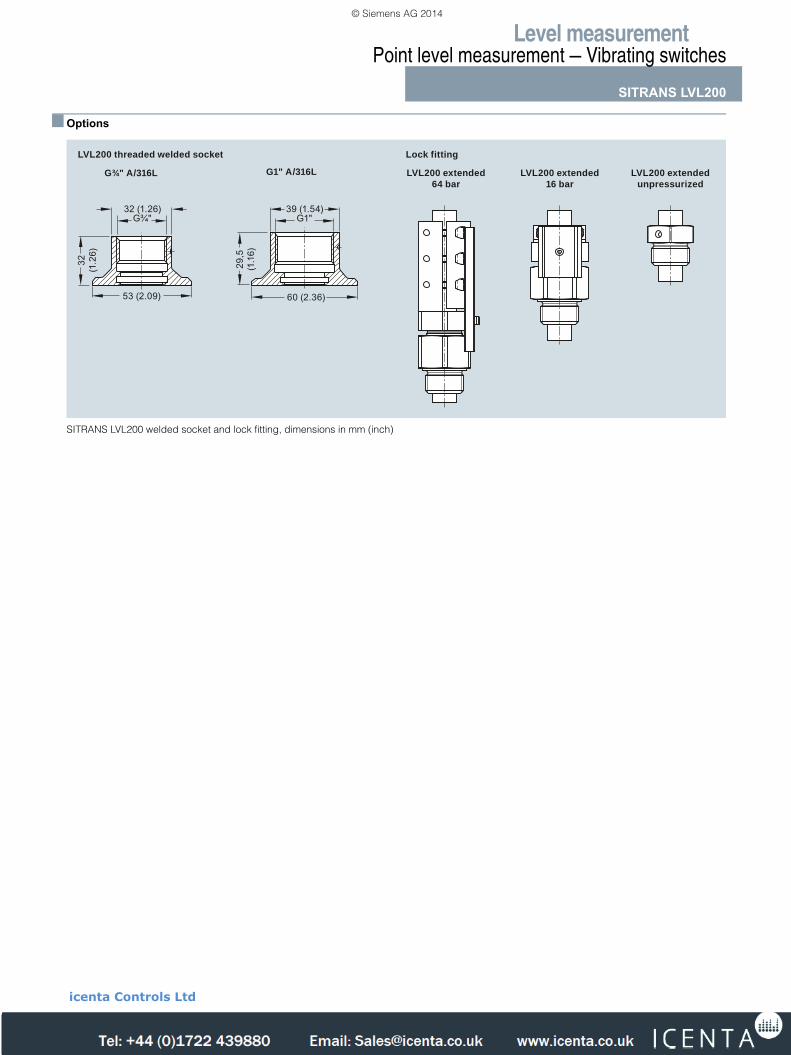
■ Options
SITRANS LVL200 welded socket and lock fitting, dimensions in mm (inch)
LVL200 extended64 bar
LVL200 threaded welded socket
LVL200 extended16 bar
LVL200 extendedunpressurized
Lock fitting
53 (2.09)
32
(1.2
6)
32 (1.26)
60 (2.36)
29,5
(1
.16)
G1"G¾"39 (1.54)
G¾" A/316L G1" A/316L
LVL200.fm Page 101 Friday, April 4, 2014 10:13 AM
© Siemens AG 2014
icenta Controls Ltd
Tel: +44 (0)1722 410777 Fax: +44 (0)1722 326818 e: [email protected] www.icenta.co.uk
Level measurementPoint level measurement — Vibrating switches
SITRANS LVL200
4/102 Siemens FI 01 · 2014
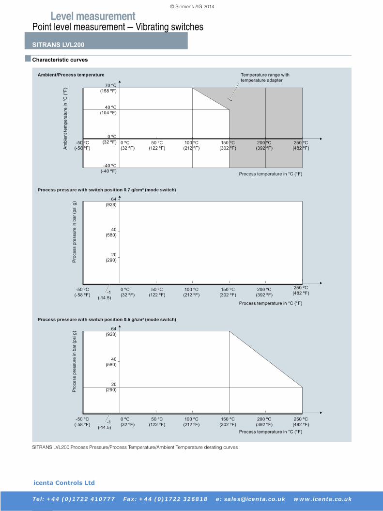
■ Characteristic curves
SITRANS LVL200 Process Pressure/Process Temperature/Ambient Temperature derating curves
Process pressure with switch position 0.7 g/cm³ (mode switch)
Process pressure with switch position 0.5 g/cm³ (mode switch)
Process temperature in °C (°F)
Process temperature in °C (°F)
Process temperature in °C (°F)
Am
bien
t tem
pera
ture
in °
C (°
F)
Temperature range with temperature adapter
Pro
cess
pre
ssur
e in
bar
(psi
g)
Pro
cess
pre
ssur
e in
bar
(psi
g)
Ambient/Process temperature
100 ºC (212 ºF)
150 ºC (302 ºF)
200 ºC (392 ºF)
250 ºC (482 ºF)
50 ºC (122 ºF)
-50 ºC (-58 ºF)
0 ºC(32 ºF) 0 ºC
(32 ºF)
0 ºC(32 ºF)
-40 ºC(-40 ºF)
40 ºC(104 ºF)
70 ºC(158 ºF)
100 ºC (212 ºF)
150 ºC (302 ºF)
200 ºC (392 ºF)
250 ºC (482 ºF)
50 ºC (122 ºF)
-50 ºC (-58 ºF)
20(290)
40(580)
64(928)
-1(-14.5)
0 ºC(32 ºF)
100 ºC (212 ºF)
150 ºC (302 ºF)
200 ºC (392 ºF)
250 ºC (482 ºF)
50 ºC (122 ºF)
-50 ºC (-58 ºF)
20(290)
40(580)
64(928)
-1(-14.5)
LVL200.fm Page 102 Friday, April 4, 2014 10:13 AM
© Siemens AG 2014
icenta Controls Ltd
Tel: +44 (0)1722 410777 Fax: +44 (0)1722 326818 e: [email protected] www.icenta.co.uk
Level measurementPoint level measurement — Vibrating switches
SITRANS LVL200
4/103Siemens FI 01 · 2014
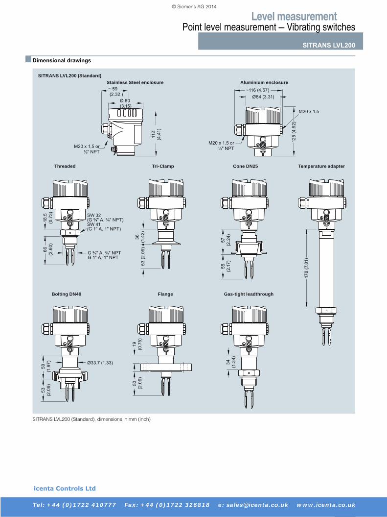
■ Dimensional drawings
SITRANS LVL200 (Standard), dimensions in mm (inch)
Temperature adapter
Bolting DN40 Flange Gas-tight leadthrough
Cone DN25Tri-ClampThreaded
SITRANS LVL200 (Standard)
M20 x 1.5 or ½" NPT
SW 32 (G ¾" A, ¾" NPT)SW 41 (G 1" A, 1" NPT)
G ¾" A, ¾" NPTG 1" A, 1" NPT
18.5
(0
.73)
M20 x 1.5
Ø33.7 (1.33)
Stainless Steel enclosure Aluminium enclosure
178
(7.0
1)
53
(2.0
9)
55
(2.1
7)53 (2
.09)
34
(1.3
4)
19
(0.7
5)
50
(1.9
7)
57
(2.2
4)36
(1.4
2)
66
(2.6
0)
125
(4.9
2)
Ø84 (3.31)~116 (4.57)
53
(2.0
9)
M20 x 1,5 or ½" NPT
~ 59 (2.32 )
Ø 80 (3.15)
112
(4.4
1)
LVL200.fm Page 103 Friday, April 4, 2014 10:13 AM
© Siemens AG 2014
icenta Controls Ltd
Tel: +44 (0)1722 410777 Fax: +44 (0)1722 326818 e: [email protected] www.icenta.co.uk
Level measurementPoint level measurement — Vibrating switches
SITRANS LVL200
4/104 Siemens FI 01 · 2014
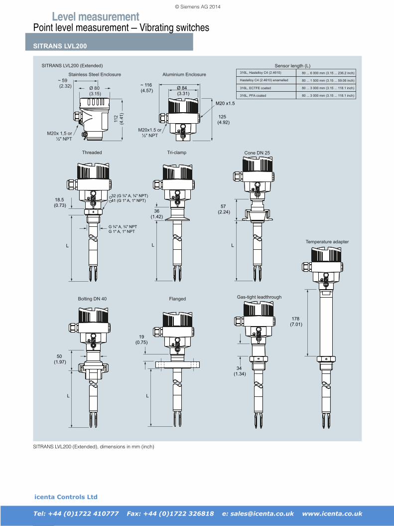
SITRANS LVL200 (Extended), dimensions in mm (inch)
SITRANS LVL200 (Extended)
Threaded Cone DN 25Tri-clamp
Bolting DN 40 Gas-tight leadthroughFlanged
Temperature adapter
Sensor length (L)316L, Hastelloy C4 (2.4610) 80 ... 6 000 mm (3.15 ... 236.2 inch)
80 ... 1 500 mm (3.15 ... 59.06 inch)
80 ... 3 000 mm (3.15 ... 118.1 inch)
80 ... 3 000 mm (3.15 ... 118.1 inch)
Hastelloy C4 (2.4610) enamelled
316L, ECTFE coated
316L, PFA coated
M20x1.5 or½" NPT
Stainless Steel Enclosure Aluminium Enclosure
Ø 84 (3.31)
125 (4.92)
M20 x1.5
G ¾" A, ¾" NPTG 1" A, 1" NPT
18.5 (0.73)
32 (G ¾" A, ¾" NPT)41 (G 1" A, 1" NPT)
36(1.42)
57 (2.24)
50 (1.97)
19(0.75)
34 (1.34)
178 (7.01)
~ 116 (4.57)
L L L
L L
M20x 1,5 or ½" NPT
~ 59 (2.32) Ø 80
(3.15)
112
(4.4
1)
LVL200.fm Page 104 Friday, April 4, 2014 10:13 AM
© Siemens AG 2014
icenta Controls Ltd
Tel: +44 (0)1722 410777 Fax: +44 (0)1722 326818 e: [email protected] www.icenta.co.uk
Level measurementPoint level measurement — Vibrating switches
SITRANS LVL200
4/105Siemens FI 01 · 2014
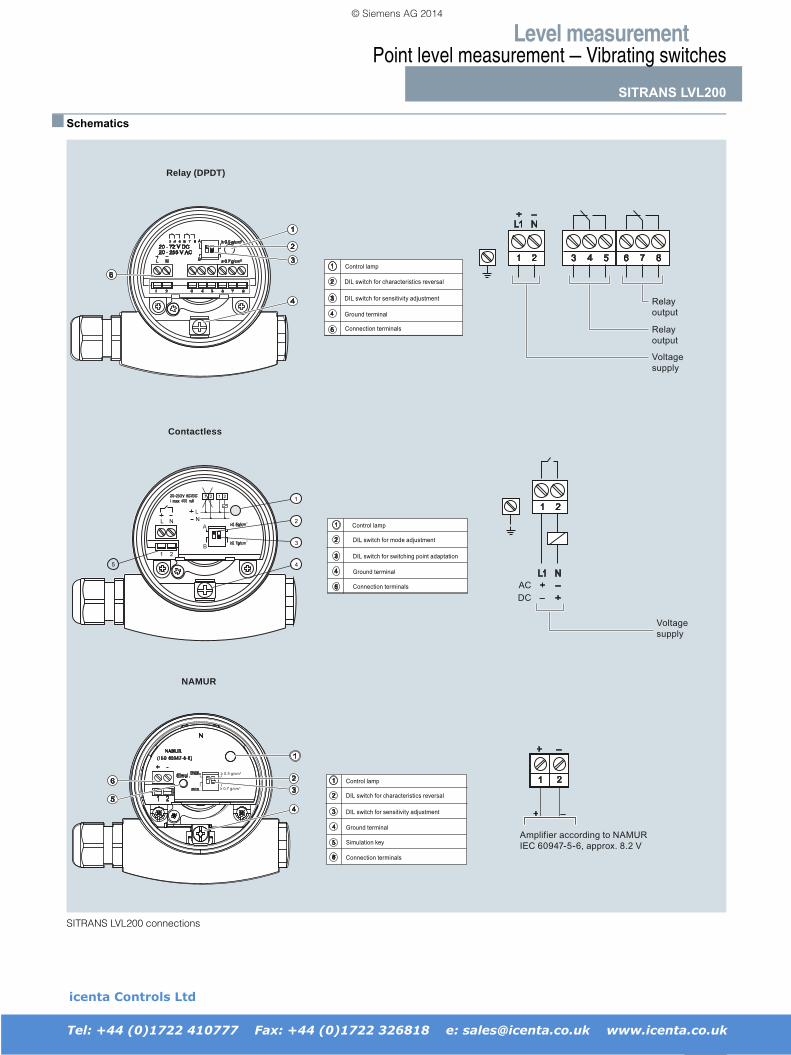
■ Schematics
SITRANS LVL200 connections
1
11 1
2
LL NN
22
2
3
45
A
B
1
23
45
6
1
2
3
4
6
Relay output
Relay output
Voltage supply
Contactless
Relay (DPDT)
DCAC
Voltage supply
Amplifier according to NAMUR IEC 60947-5-6, approx. 8.2 V
Control lamp
DIL switch for characteristics reversal
DIL switch for sensitivity adjustment
Ground terminal
Simulation key
Connection terminals
20 - 253 V AC20 - 72 V DC
Control lamp
DIL switch for mode adjustment
DIL switch for switching point adaptation
Ground terminal
Connection terminals
DIL switch for characteristics reversal
DIL switch for sensitivity adjustment
Ground terminal
Connection terminals
Control lamp
2 0 - 2 5 3 V A C / D CI m a x 4 0 0 m A
NL1–+
–+– +
21 4 53 7 86
21
NL1
21
–+
–+
N
N A M U R( I E C 6 0 9 4 7 - 5 - 6 )
m a x .
m i n .
S i m u l .+ -
1 2
NAMUR
1
2
3
4
5
1
2
3
4
5
1
2
3
4
5
6
≥ 0 . 5 g / c m
≥ 0 . 7 g / c m
LVL200.fm Page 105 Friday, April 4, 2014 10:13 AM
© Siemens AG 2014
icenta Controls Ltd
Tel: +44 (0)1722 410777 Fax: +44 (0)1722 326818 e: [email protected] www.icenta.co.uk