Embed Size (px)
Citation preview

PB SERIESBALL VALVES •CHECK VALVES
& MANIFOLD COMPONENTS
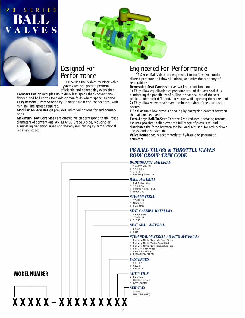
Engineered For PerformancePB Series Ball Valves are engineered to perform well under
diverse pressure and flow situations, and offer the economy ofrepairability.Removable Seat Carriers serve two important functions:1) They allow equalization of pressure around the seat seal thuseliminating the possibility of pulling a seat seal out of the seatpocket under high differential pressure while opening the valve; and2) They allow valve repair even if minor erosion of the seat pocketoccurs.L-Seal assures low pressure sealing by energizing contact betweenthe ball and seat seal.Extra-Large Ball-To-Seat Contact Area reduces operating torque,assures positive sealing over the full range of pressures, anddistributes the force between the ball and seat seal for reduced wearand extended service life.Valve Bonnet easily accommodates hydraulic or pneumaticactuators.
Designed ForPerformance
PB Series Ball Valves by Piper ValveSystems are designed to performefficiently and dependably every time.
Compact Design occupies up to 40% less space than conventionalflanged-end ball valves for skids or manifolds where space is critical.Easy Removal From Service by unbolting from end connections, withminimal line spread required.Modular 3-Piece Design provides unlimited options for end connec-tions.Maximum Flow Bore Sizes are offered which correspond to the insidediameters of conventional ASTM A106 Grade B pipe, reducing oreliminating transition areas and thereby minimizing system frictionalpressure losses.
2
P B S E R I E S
BALLV A L V E S
PB BALL VALVES & THROTTLE VALVESBODY GROUP TRIM CODEBODY/BONNET MATERIAL:1 Standard Material2 17-4PH SS3 316 SS4 Low Temp Alloy Steel
BALL MATERIAL1 ENP Carbon Steel2 17-4PH SS3 Chrome Plated 316 SS4 Nitronic 60
STEM MATERIAL1 17-4PH SS2 Nitronic 603 K500 Monel
SEAT CARRIER MATERIAL:1 Carbon Steel2 17-4PH SS3 316 SS
SEAT SEAL MATERIAL:1 Celcon2 PEEK
STEM SEAL MATERIAL / O-RING MATERIAL:1 PolyMyte-Nitrile / Peroxide-Cured Nitrile2 PolyMyte-Nitrile / Sulfur-Cured Nitrile3 PolyMyte-Nitrile / Low Temperature Nitrile4 PolyMyte-Viton / Viton5 Viton-Viton / Viton6 EPDM-EPDM / EPDM
FASTENERS:1 A193-B72 A320-L73 A320-L7M
ACTUATION:0 Bare Stem1 Handle-Operated2 Gear Operator
SERVICE:1 Standard2 NACE (MR01-75)
X X X X X – X X X X X X X X X
MODEL NUMBER
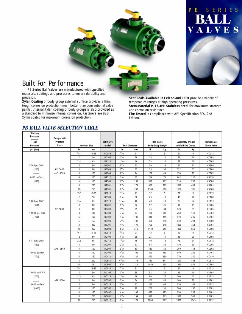
Built For PerformancePB Series Ball Valves are manufactured with specified
materials, coatings and processes to ensure durability andprecision.Xylan Coating of body group external surface provides a thin,tough corrosion protection much better than conventional valvepaints. Internal Xylan coating of body groups is also provided asa standard to minimize internal corrosion. Fasteners are alsoXylan coated for maximum corrosion protection.
Seat Seals Available In Celcon and PEEK provide a variety oftemperature ranges at high operating pressures.Stem Material Is 17-4PH Stainless Steel for maximum strengthand corrosion resistance.Fire Tested in compliance with API Specification 6FA, 2ndEdition.
3
P B S E R I E S
BALLV A L V E S
PB BALL VALVE SELECTION TABLEWorkingPressure–––––– Comparable
Test Pressure Ball Valve Ball Valve Assembly Weight CompanionPressure Class Nominal Size Model Port Diameter Body Group Weight w/Weld End Conns. Check Valve
psi (bar) in mm in mm lb kg lb kg1/2-1 12-25 BCO13 13/16 21 12 5 20 9 CC013
2 50 BC108 11/2 38 25 11 43 20 CC108
21/2 65 BA113 113/16 46 23 10 36 16 CC108
3,705 psi CWP 3 80 BA201 21/16 52 30 14 50 23 CA200
(250) API 3000 3 80 BB209 29/16 65 75 34 122 55 CC206
––––– ANSI 1500 4 100 BA305 35/16 84 108 49 170 77 CC302
6,000 psi Test 4 100 BA312 33/4 95 164 75 242 110 CA310
(420) 6 150 BA503 53/16 132 390 177 510 232 CA500
8 200 BA701 71/16 179 680 309 1010 459 CA701
10 250 BA901 91/16 230 1100 500 1550 705 CA8081/2-1 12-25 BC013 13/16 21 12 5 20 9 CC013
2 50 BC108 11/2 38 25 11 43 20 CC108
5,000 psi CWP 21/2 65 BC113 113/16 46 40 18 75 34 CC113
(350) 3 80 BB201 21/16 52 57 26 90 41 CC206
––––– API 5000 3 80 BB209 29/16 65 75 34 120 55 CC206
10,000 psi Test 4 100 BC304 31/4 83 180 82 260 118 CC302
(700) 6 150 BC402 41/8 105 340 155 540 245 CC401
6 150 BB503 53/16 132 480 218 640 291 CB500
8 200 BB701 71/16 179 700 318 1020 464 CB701
10 250 BC808 81/2 216 1440 655 1890 859 CC8081/2-1 12-25 BC013 13/16 21 12 5 20 9 CC013
2 50 BC108 11/2 38 25 11 43 20 CC108
6,170 psi CWP 21/2 65 BC113 113/16 46 40 18 75 34 CC113
(420) 3 80 BC204 21/4 57 84 38 130 59 CC206
––––– ANSI 2500 4 100 BC304 31/4 83 180 82 260 118 CC302
10,000 psi Test 6 150 BC402 41/8 105 340 155 540 245 CC401
(700) 6 150 BC412 43/4 121 550 250 770 350 CC410
8 200 BC613 613/16 173 750 341 1070 486 CC613
10 250 BC808 81/2 216 1440 655 1890 859 CC8081/2-1 12-25 BD013 13/16 21 12 5 20 9 CD013
10,000 psi CWP 2 50 BD108 11/2 38 52 24 89 40 CD108
(700) 21/2 65 BD113 113/16 46 60 27 100 45 CD113
_____ API 10000 3 80 BD202 21/8 54 100 45 160 73 CD201
15,000 psi Test 3 80 BD210 25/8 67 150 68 230 105 CD212
(1,050) 4 100 BD302 31/8 79 200 91 300 136 CD301
6 150 BD402 41/8 105 430 195 650 295 CD401
8 200 BD601 61/16 154 820 373 1120 509 CD601
10 250 BD712 73/4 174 1600 727 2300 1045 CD712
ComparablePressure
Class
4
P B S E R I E S
BALLV A L V E S
12
3
5
6
7
8
9
10
11
12
13
14
15
16
17
1819
20
1213
14
17 21
22
23
24
25
2627
2324
25
4
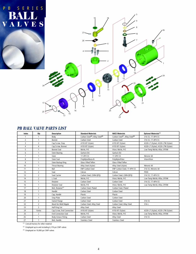
PB BALL VALVE PARTS LISTIndex Qty Description Standard Materials NACE Materials Optional Materials(1)
1 1 Body Carbon Steel(2); Alloy Steel(3) Carbon Steel(2 ; Alloy Steel(3) 316 SS; 17-4PH SS
2 1 Bonnet Carbon Steel Carbon Steel 316 SS; 17-4PH SS
3 2 Cap Screw, Stop A193-B7 (Xylan) A193-B7 (Xylan) A320-L7 (Xylan); A320-L7M (Xylan)
4 4 Cap Screw, Bonnet A193-B7 (Xylan) A193-B7 (Xylan) A320-L7 (Xylan); A320-L7M (Xylan)
5 1 Bonnet Seal Nitrile, P/C Viton; Nitrile, P/C Low Temp Nitrile; Aflas; EPDM
6 1 Stem Bearing Garlock DU Garlock DU
7 1 Stem 17-4PH SS 17-4PH SS Nitronic 60
8 1 Stem Seal PolyMyte/Buna-N PolyMyte/Viton Viton/Viton
9 1 Stem Backup Ring Glass-Filled Teflon Glass-Filled Teflon
10 1 Thrust Bearing Alloy Steel (Xylan) Alloy Steel (Xylan) Nitronic 60
11 1 Ball ENP Carbon Steel ENP Carbon Steel; 17-4PH SS 316 SS; Nitronic 60
12 2 Seat Celcon Celcon PEEK
13 2 Seat Carrier Carbon Steel; (SBN-QPQ) Carbon Steel; (SBN-QPQ) 316 SS; 17-4PH SS
14 2 L-Seal Nitrile, P/C Viton; Nitrile, P/C Low Temp Nitrile; Aflas; EPDM
15 1 Retainer Carbon Steel Carbon Steel 316 SS; 17-4PH-SS
16 1 Retainer Seal Nitrile, P/C Viton; Nitrile, P/C Low Temp Nitrile; Aflas; EPDM
17 2 Bolt, Retainer(5) Carbon Steel, Plated Carbon Steel, Plated
18 1 Handle Carbon Steel Carbon Steel
19 1 Cap, Handle Plastic Plastic
20 1 Stop Plate Carbon Steel Carbon Steel
21 2 Swivel Flange Carbon Steel Carbon Steel 316 SS
22 2 Bevel-for-Weld Nipple Carbon Steel; Alloy Steel Carbon Steel; Alloy Steel 316-L
23 2 Half Ring Set Alloy Steel Alloy Steel
24 Varies Cap Screw, End Connection A193-B7 (Xylan) A193-B7 (Xylan) A320-L7 (Xylan); A320-L7M (Xylan)
25 2 End Connection Seal Nitrile, P/C Viton; Nitrile, P/C Low Temp Nitrile; Aflas; EPDM
26 1 Body Grease Fitting Carbon Steel Alloy Steel 316 SS
27 1 Bolt, Handle Stainless Steel Stainless Steel(1) Consult factory for other material(2) Employed up to and including 6,170 psi CWP valves(3) Employed on 10,000 psi CWP valves
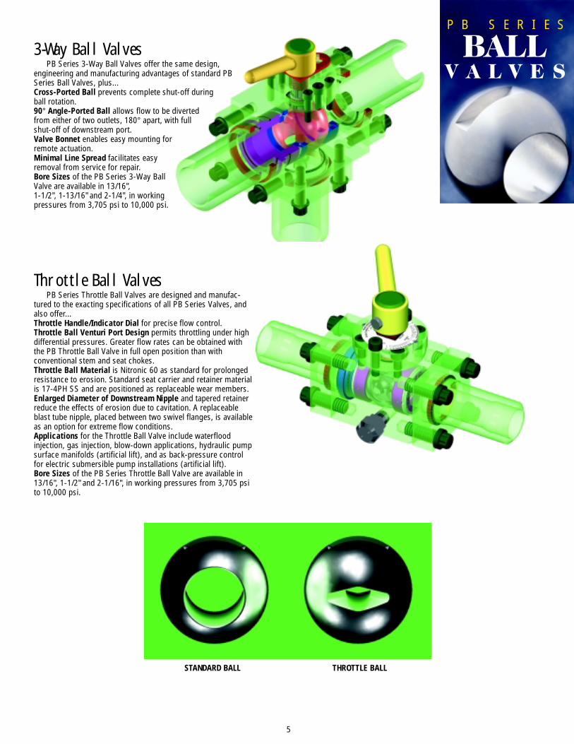
Throttle Ball ValvesPB Series Throttle Ball Valves are designed and manufac-
tured to the exacting specifications of all PB Series Valves, andalso offer...Throttle Handle/Indicator Dial for precise flow control.Throttle Ball Venturi Port Design permits throttling under highdifferential pressures. Greater flow rates can be obtained withthe PB Throttle Ball Valve in full open position than withconventional stem and seat chokes.Throttle Ball Material is Nitronic 60 as standard for prolongedresistance to erosion. Standard seat carrier and retainer materialis 17-4PH SS and are positioned as replaceable wear members.Enlarged Diameter of Downstream Nipple and tapered retainerreduce the effects of erosion due to cavitation. A replaceableblast tube nipple, placed between two swivel flanges, is availableas an option for extreme flow conditions.Applications for the Throttle Ball Valve include waterfloodinjection, gas injection, blow-down applications, hydraulic pumpsurface manifolds (artificial lift), and as back-pressure controlfor electric submersible pump installations (artificial lift).Bore Sizes of the PB Series Throttle Ball Valve are available in13/16", 1-1/2" and 2-1/16", in working pressures from 3,705 psito 10,000 psi.
3-Way Ball ValvesPB Series 3-Way Ball Valves offer the same design,
engineering and manufacturing advantages of standard PBSeries Ball Valves, plus...Cross-Ported Ball prevents complete shut-off duringball rotation.90° Angle-Ported Ball allows flow to be divertedfrom either of two outlets, 180° apart, with fullshut-off of downstream port.Valve Bonnet enables easy mounting forremote actuation.Minimal Line Spread facilitates easyremoval from service for repair.Bore Sizes of the PB Series 3-Way BallValve are available in 13/16",1-1/2", 1-13/16" and 2-1/4", in workingpressures from 3,705 psi to 10,000 psi.
5
P B S E R I E S
BALLV A L V E S
STANDARD BALL THROTTLE BALL

Engineered For PerformancePB Series Check Valves are engineered to perform well under
diverse pressure and flow situations, and offer the economy ofrepairability.Wafer Body Style provides short end-to-end dimension and iseasily removed from service for repair.Fire-Safe Design is the result of metal-to-metal secondarysealing in critical areas.Ball Valve/Check Valve Combination Assemblies offer theshortest overall length available. For even greater space savings,smaller size check valves can be direct-bolted to the ball valve.
Designed For PerformancePB Series Check Valves by Piper Valve Systems are designed
under the same stringent specifications as PB Series Ball Valves.Compact Design occupies up to 40% less space than conven-tional flanged-end check valves for skids or manifolds wherespace is critical.Easy Removal From Service by unbolting from end connections,with minimal line spread required.Modular 3-Piece Design provides unlimited options for endconnections.Maximum Flow Bore Sizes are offered which correspond to theinside diameters of conventional ASTM A106 Grade B pipe,reducing or eliminating transition areas and thereby minimizingsystem frictional pressure losses.
6
PB CHECK VALVE BODY GROUP TRIM CODEBODY MATERIAL:1 Standard Material2 17-4PH SS3 316 SS4 Low Temp. Alloy Steel
FLAPPER MATERIAL:1 17-4PH SS2 Nitronic 603 316 SS
RETAINER - SEAT CARRIER MATERIAL:1 17-4PH SS2 316 SS3 Carbon Steel4 Alloy Steel
O-RING SEALS:1 Peroxide-Cured Nitrile2 Sulphur-Cured Nitrile3 Low Temperature Nitrile4 Viton5 EPDM6 Aflas
CHECK VALVE ORIENTATION:1 Other Than Vertical Downflow2 Vertical Downflow
X X X X X – X X X X X
MODEL NUMBER
P B S E R I E S
CHECKV A L V E S
P B S E R I E S
CHECKV A L V E S
7
PB CHECK VALVE SELECTION TABLEWorkingPressure–––––– Comparable
Test Pressure Check Valve Check Valve Assembly Weight CompanionPressure Class Nominal Size Model Port Diameter Body Group Weight w/Weld End Conns Ball Valve
psi (bar) in mm in mm lb kg lb kg1/2-1 12-25 CCO13 13/16 21 8 4 16 7 BC013
2 50 CC108 11/2 38 15 7 29 13 BC108
21/2 65 CC113 113/16 46 35 16 69 31 BC113
3,705 psi CWP 3 80 CA200 2 51 17 8 38 17 BA201
(250) API 3000 3 80 CC206 23/8 60 29 13 65 30 BB209
––––– ANSI 1500 4 100 CC302 31/8 79 66 30 126 57 BA305
6,000 psi Test 4 100 CA310 35/8 92 62 28 123 56 BA312
(420) 6 150 CA500 5 127 120 55 220 100 BA503
8 200 CA701 71/16 179 330 150 610 277 BA701
10 250 CA808 81/2 216 440 200 840 382 BA9011/2-1 12-25 CC013 13/16 21 8 4 16 7 BC013
2 50 CC108 11/2 38 15 7 29 13 BC108
5,000 psi CWP 21/2 65 CC113 113/16 46 35 16 69 31 BC113
(350) 3 80 CC206 23/8 60 29 13 65 30 BC204
––––– API 5000 4 100 CC302 31/8 79 65 30 126 57 BC302
10,000 psi Test 6 150 CC401 41/16 103 200 91 400 182 BC401
(700) 6 150 CB500 5 127 200 91 400 182 BB503
8 200 CB701 71/16 179 330 150 610 277 BB701
10 250 CC808 81/2 216 440 200 840 382 BC8081/2-1 12-25 CC013 13/16 21 8 4 16 7 BC013
2 50 CC108 11/2 38 15 7 29 13 BC108
6,170 psi CWP 21/2 65 CC113 113/16 46 35 16 69 31 BC113
(420) 3 80 CC206 23/8 60 29 13 65 30 BC204
––––– ANSI 2500 4 100 CC302 31/8 79 65 30 126 57 BC302
10,000 psi Test 6 150 CC401 41/16 103 200 91 400 182 BC401
(700) 6 150 CC410 45/8 117 200 91 400 182 BC412
8 200 CC613 613/16 173 330 150 610 277 BC613
10 250 CC808 81/2 216 440 200 840 382 BC8081/2-1 12-25 CD013 13/16 21 8 4 16 7 BD013
10,000 psi CWP 2 50 CD108 11/2 38 40 18 72 33 BD108
(700) 21/2 65 CD113 113/16 46 40 18 72 33 BD113
_____ API 10000 3 80 CD201 21/16 52 46 21 88 40 BD202
15,000 psi Test 3 80 CD212 23/4 70 110 50 190 86 BD210
(1,050) 4 100 CD301 31/16 78 110 50 190 86 BD302
6 150 CD401 41/16 103 200 91 400 182 BD402
8 200 CD601 61/16 154 340 155 660 300 BD601
10 250 CD712 73/4 174 580 264 1050 477 BD712
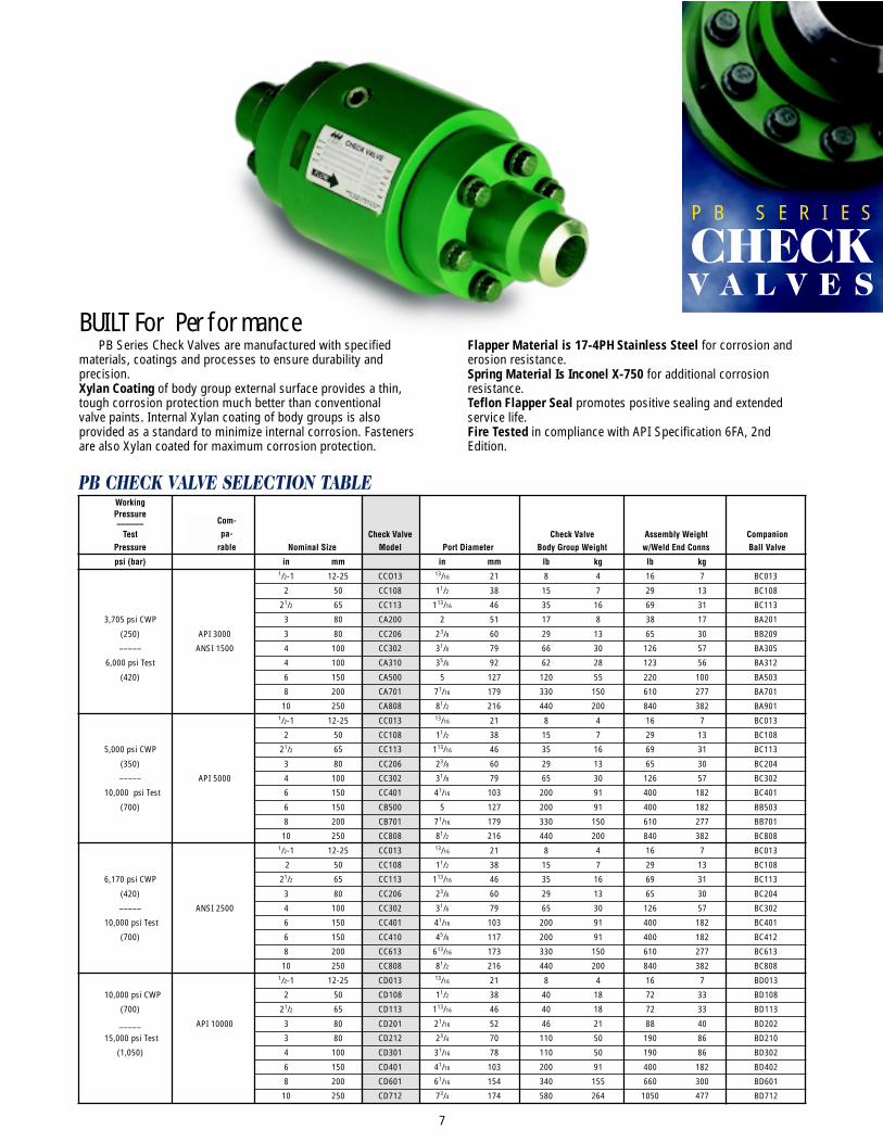
BUILT For PerformancePB Series Check Valves are manufactured with specified
materials, coatings and processes to ensure durability andprecision.Xylan Coating of body group external surface provides a thin,tough corrosion protection much better than conventionalvalve paints. Internal Xylan coating of body groups is alsoprovided as a standard to minimize internal corrosion. Fastenersare also Xylan coated for maximum corrosion protection.
Flapper Material is 17-4PH Stainless Steel for corrosion anderosion resistance.Spring Material Is Inconel X-750 for additional corrosionresistance.Teflon Flapper Seal promotes positive sealing and extendedservice life.Fire Tested in compliance with API Specification 6FA, 2ndEdition.
Com-pa-
rable
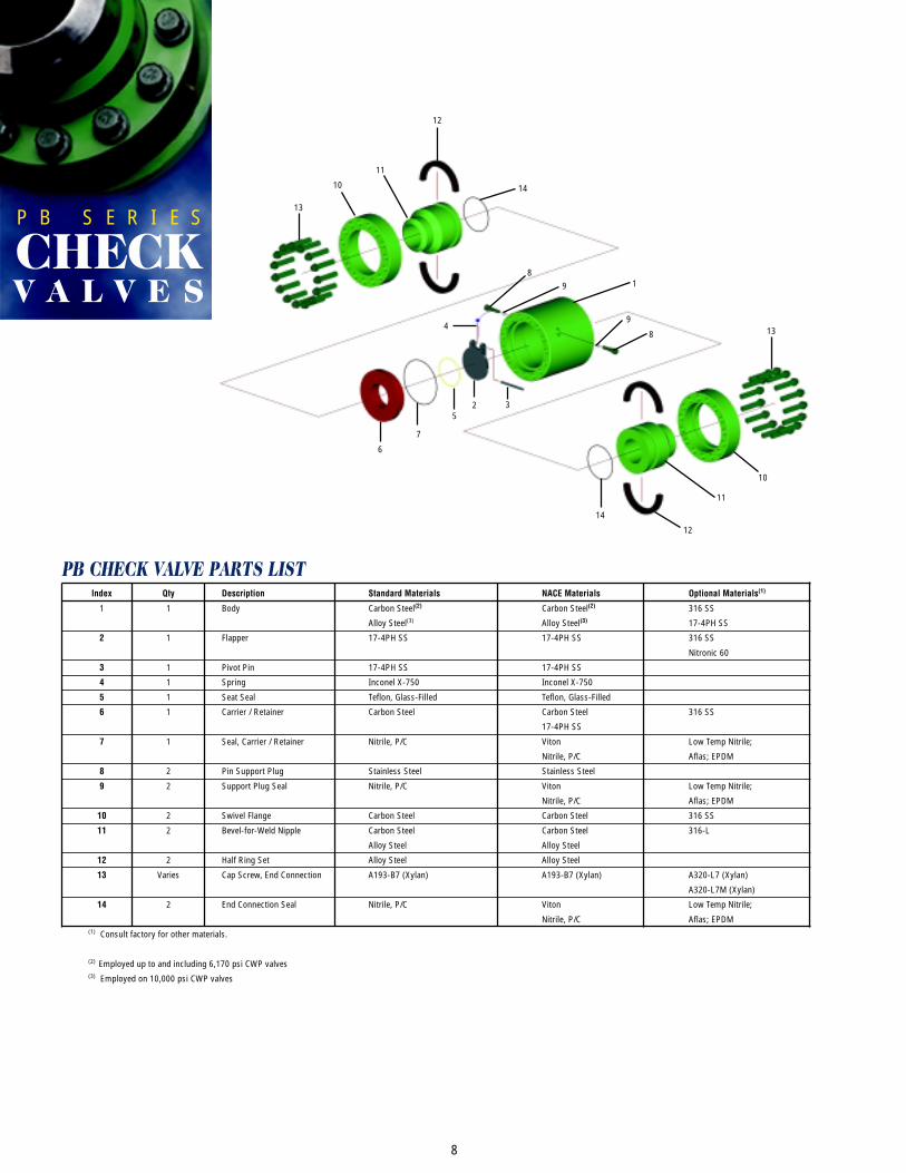
PB CHECK VALVE PARTS LISTIndex Qty Description Standard Materials NACE Materials Optional Materials(1)
1 1 Body Carbon Steel(2) Carbon Steel(2) 316 SS
Alloy Steel(3) Alloy Steel(3) 17-4PH SS
2 1 Flapper 17-4PH SS 17-4PH SS 316 SS
Nitronic 60
3 1 Pivot Pin 17-4PH SS 17-4PH SS
4 1 Spring Inconel X-750 Inconel X-750
5 1 Seat Seal Teflon, Glass-Filled Teflon, Glass-Filled
6 1 Carrier / Retainer Carbon Steel Carbon Steel 316 SS
17-4PH SS
7 1 Seal, Carrier / Retainer Nitrile, P/C Viton Low Temp Nitrile;
Nitrile, P/C Aflas; EPDM
8 2 Pin Support Plug Stainless Steel Stainless Steel
9 2 Support Plug Seal Nitrile, P/C Viton Low Temp Nitrile;
Nitrile, P/C Aflas; EPDM
10 2 Swivel Flange Carbon Steel Carbon Steel 316 SS
11 2 Bevel-for-Weld Nipple Carbon Steel Carbon Steel 316-L
Alloy Steel Alloy Steel
12 2 Half Ring Set Alloy Steel Alloy Steel
13 Varies Cap Screw, End Connection A193-B7 (Xylan) A193-B7 (Xylan) A320-L7 (Xylan)
A320-L7M (Xylan)
14 2 End Connection Seal Nitrile, P/C Viton Low Temp Nitrile;
Nitrile, P/C Aflas; EPDM(1) Consult factory for other materials.
(2) Employed up to and including 6,170 psi CWP valves(3) Employed on 10,000 psi CWP valves
8
11
12
13
14
1
2 3
4
5
6
7
89
10
8
9
11
12
13
14
10
P B S E R I E S
CHECKV A L V E S
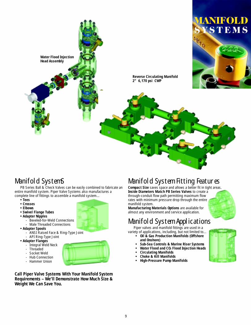
Manifold System Fitting FeaturesCompact Size saves space and allows a better fit in tight areas.Inside Diameters Match PB Series Valves to create athrough-conduit flow path permitting maximum flowrates with minimum pressure drop through the entiremanifold system.Manufacturing Materials Options are available foralmost any environment and service application.
Manifold System ApplicationsPiper valves and manifold fittings are used in a
variety of applications, including, but not limited to...• Oil & Gas Production Manifolds (Offshore
and Onshore)• Sub-Sea Controls & Marine Riser Systems• Water Flood and CO2 Flood Injection Heads• Circulating Manifolds• Choke & Kill Manifolds• High-Pressure Pump Manifolds
Manifold SystemSPB Series Ball & Check Valves can be easily combined to fabricate an
entire manifold system. Piper Valve Systems also manufactures acomplete line of fittings to assemble a manifold system...
• Tees• Crosses• Elbows• Swivel Flange Tubes• Adapter Nipples
- Beveled-for-Weld Connections- Male Threaded Connections
• Adapter Spools- ANSI Raised Face & Ring-Type Joint- API Ring-Type Joint
• Adapter Flanges- Integral Weld Neck- Threaded- Socket Weld- Hub Connection- Hammer Union
Call Piper Valve Systems With Your Manifold SystemRequirements – We’ll Demonstrate How Much Size &Weight We Can Save You.
9
Water Flood InjectionHead Assembly
Reverse Circulating Manifold2” 6,170 psi CWP
MANIFOLDS Y S T E M S
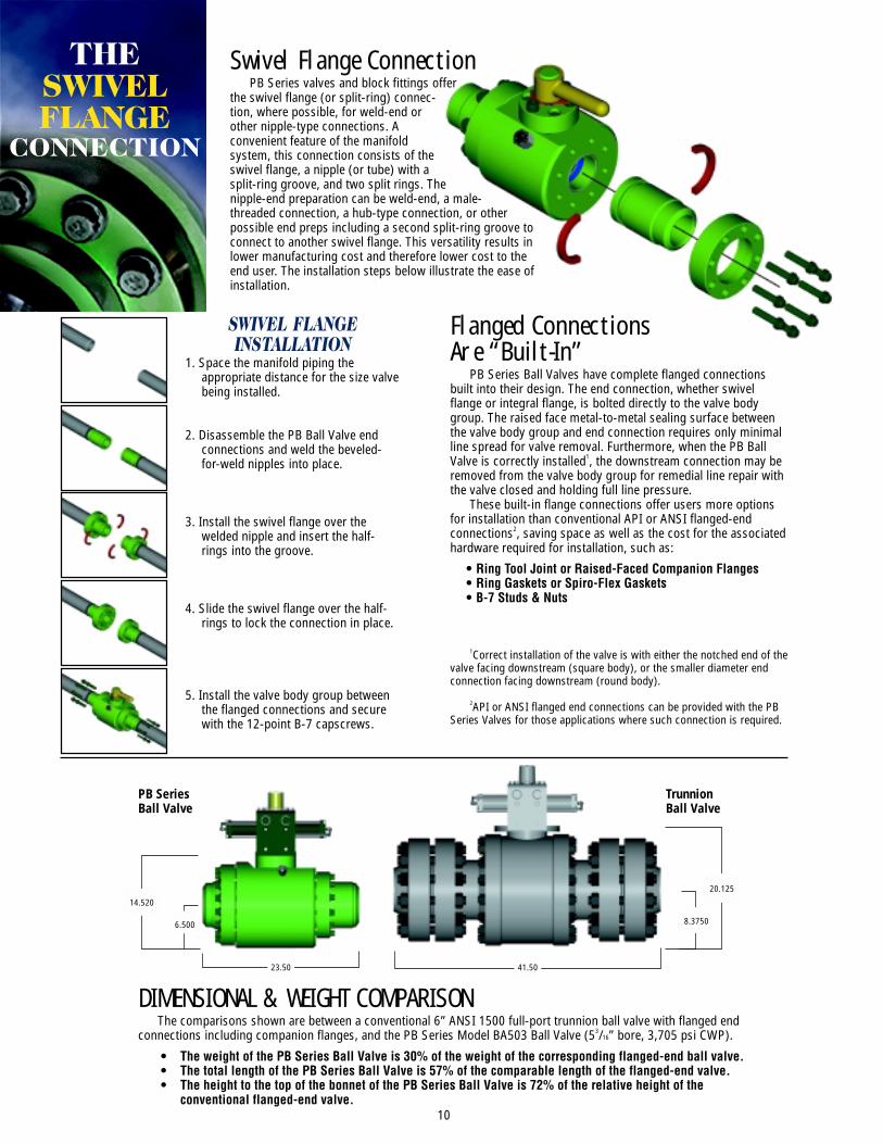
DIMENSIONAL & WEIGHT COMPARISONThe comparisons shown are between a conventional 6” ANSI 1500 full-port trunnion ball valve with flanged end
connections including companion flanges, and the PB Series Model BA503 Ball Valve (53/16” bore, 3,705 psi CWP).
• The weight of the PB Series Ball Valve is 30% of the weight of the corresponding flanged-end ball valve.• The total length of the PB Series Ball Valve is 57% of the comparable length of the flanged-end valve.• The height to the top of the bonnet of the PB Series Ball Valve is 72% of the relative height of the
conventional flanged-end valve.
Flanged ConnectionsAre “Built-In”
PB Series Ball Valves have complete flanged connectionsbuilt into their design. The end connection, whether swivelflange or integral flange, is bolted directly to the valve bodygroup. The raised face metal-to-metal sealing surface betweenthe valve body group and end connection requires only minimalline spread for valve removal. Furthermore, when the PB BallValve is correctly installed1, the downstream connection may beremoved from the valve body group for remedial line repair withthe valve closed and holding full line pressure.
These built-in flange connections offer users more optionsfor installation than conventional API or ANSI flanged-endconnections2, saving space as well as the cost for the associatedhardware required for installation, such as:
• Ring Tool Joint or Raised-Faced Companion Flanges• Ring Gaskets or Spiro-Flex Gaskets• B-7 Studs & Nuts
1Correct installation of the valve is with either the notched end of thevalve facing downstream (square body), or the smaller diameter endconnection facing downstream (round body).
2API or ANSI flanged end connections can be provided with the PBSeries Valves for those applications where such connection is required.
SWIVEL FLANGEINSTALLATION
1. Space the manifold piping theappropriate distance for the size valvebeing installed.
2. Disassemble the PB Ball Valve endconnections and weld the beveled-for-weld nipples into place.
3. Install the swivel flange over thewelded nipple and insert the half-rings into the groove.
4. Slide the swivel flange over the half-rings to lock the connection in place.
5. Install the valve body group betweenthe flanged connections and securewith the 12-point B-7 capscrews.
Swivel Flange ConnectionPB Series valves and block fittings offer
the swivel flange (or split-ring) connec-tion, where possible, for weld-end orother nipple-type connections. Aconvenient feature of the manifoldsystem, this connection consists of theswivel flange, a nipple (or tube) with asplit-ring groove, and two split rings. Thenipple-end preparation can be weld-end, a male-threaded connection, a hub-type connection, or otherpossible end preps including a second split-ring groove toconnect to another swivel flange. This versatility results inlower manufacturing cost and therefore lower cost to theend user. The installation steps below illustrate the ease ofinstallation.
23.50
6.500
14.520
41.50
20.125
8.3750
10
PB SeriesBall Valve
TrunnionBall Valve
THESWIVELFLANGE
CONNECTION
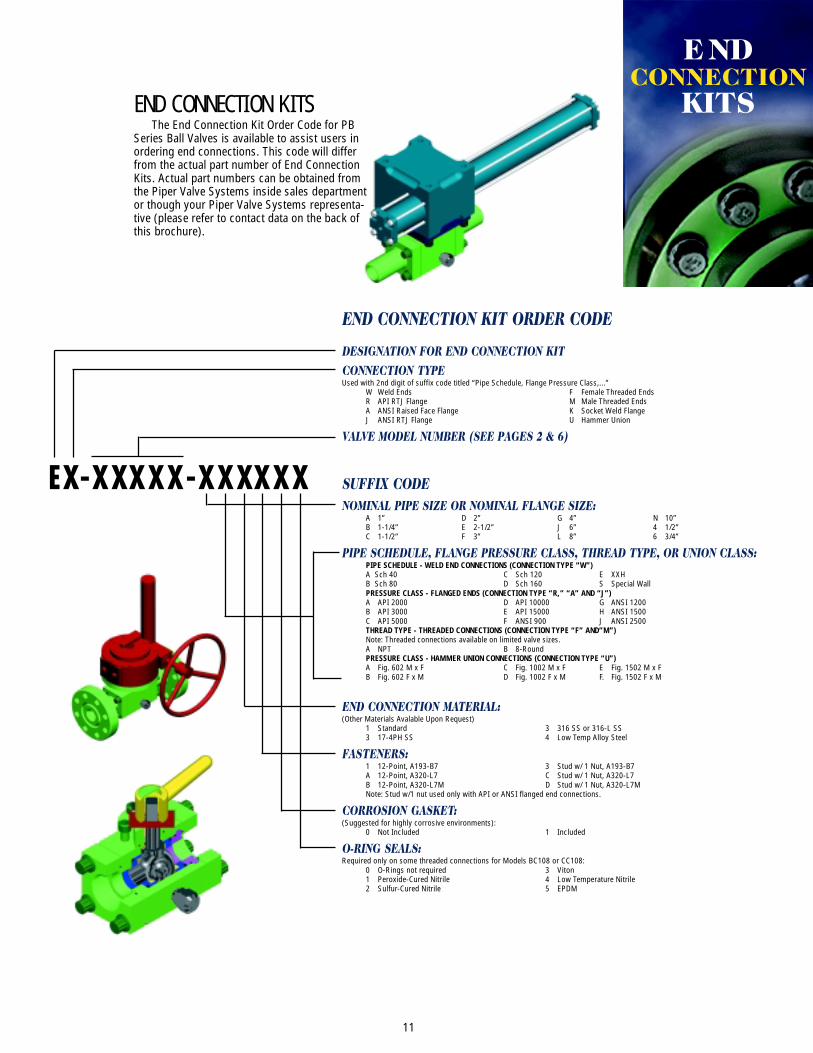
END CONNECTION KITSThe End Connection Kit Order Code for PB
Series Ball Valves is available to assist users inordering end connections. This code will differfrom the actual part number of End ConnectionKits. Actual part numbers can be obtained fromthe Piper Valve Systems inside sales departmentor though your Piper Valve Systems representa-tive (please refer to contact data on the back ofthis brochure).
11
DESIGNATION FOR END CONNECTION KITCONNECTION TYPEUsed with 2nd digit of suffix code titled “Pipe Schedule, Flange Pressure Class,...”
W Weld Ends F Female Threaded EndsR API RTJ Flange M Male Threaded EndsA ANSI Raised Face Flange K Socket Weld FlangeJ ANSI RTJ Flange U Hammer Union
VALVE MODEL NUMBER (SEE PAGES 2 & 6)
SUFFIX CODENOMINAL PIPE SIZE OR NOMINAL FLANGE SIZE:
A 1” D 2” G 4” N 10”B 1-1/4” E 2-1/2” J 6” 4 1/2”C 1-1/2” F 3” L 8” 6 3/4”
PIPE SCHEDULE, FLANGE PRESSURE CLASS, THREAD TYPE, OR UNION CLASS:PIPE SCHEDULE - WELD END CONNECTIONS (CONNECTION TYPE “W”)A Sch 40 C Sch 120 E XXHB Sch 80 D Sch 160 S Special WallPRESSURE CLASS - FLANGED ENDS (CONNECTION TYPE “R,” “A” AND “J”)A API 2000 D API 10000 G ANSI 1200B API 3000 E API 15000 H ANSI 1500C API 5000 F ANSI 900 J ANSI 2500THREAD TYPE - THREADED CONNECTIONS (CONNECTION TYPE “F” AND”M”)Note: Threaded connections available on limited valve sizes.A NPT B 8-RoundPRESSURE CLASS - HAMMER UNION CONNECTIONS (CONNECTION TYPE “U”)A Fig. 602 M x F C Fig. 1002 M x F E Fig. 1502 M x FB Fig. 602 F x M D Fig. 1002 F x M F. Fig. 1502 F x M
END CONNECTION MATERIAL:(Other Materials Avalable Upon Request)
1 Standard 3 316 SS or 316-L SS3 17-4PH SS 4 Low Temp Alloy Steel
FASTENERS:1 12-Point, A193-B7 3 Stud w/ 1 Nut, A193-B7A 12-Point, A320-L7 C Stud w/ 1 Nut, A320-L7B 12-Point, A320-L7M D Stud w/ 1 Nut, A320-L7MNote: Stud w/1 nut used only with API or ANSI flanged end connections.
CORROSION GASKET:(Suggested for highly corrosive environments):
0 Not Included 1 Included
O-RING SEALS:Required only on some threaded connections for Models BC108 or CC108:
0 O-Rings not required 3 Viton1 Peroxide-Cured Nitrile 4 Low Temperature Nitrile2 Sulfur-Cured Nitrile 5 EPDM
EX-XXXXX-XXXXXX
END CONNECTION KIT ORDER CODE
E NDCONNECTION
KITS
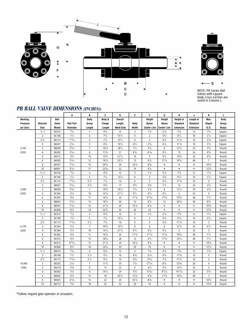
PB BALL VALVE DIMENSIONS (INCHES):A B C D E F G H J K L
Working Ball Body Body & Overall Height Height Height of Length of Max. Body
Pressure Nominal Valve Ball Port Group Flange Length, Body Below Above Standard Standard Nipple Group
psi (bar) Size Model Diameter Length Length Weld Ends Width Center Line Center Line Extension Extension O.D. Shape1/2 -1 BC013 13/16 4 65/8 12 3 11/2 51/4 77/8 12 13/4 Square
2 BC108 11/2 5 71/2 151/2 4 2 53/4 91/2 16 21/2 Square
21/2 BA113 113/16 5 71/4 151/2 4 2 61/2 111/4 16 27/8 Square
3 BA201 21/16 5 81/8 161/2 41/2 21/4 61/2 111/4 16 31/2 Square
3,705 3 BB209 29/16 7 105/8 181/2 71/2 31/2 8 121/2 24 33/4 Round
(250) 4 BA305 35/16 8 113/4 21 87/8 47/16 81/2 13 24 65/8 Round
4 BA312 33/4 10 133/4 211/2 10 5 91/2 145/8 32 65/8 Round
6 BA503 53/16 12 163/8 231/2 13 61/2 113/4 191/2 48 7 Round
8 BA701 71/16 15 207/8 29 161/4 81/8 * * * 103/4 Round
10 BA901 91/16 17 233/8 32 19 91/2 * * * 123/4 Round1/2 -1 BC018 13/16 4 65/8 12 3 11/2 51/4 77/8 12 13/4 Square
2 BC108 11/2 5 71/2 151/2 4 2 53/4 91/2 16 21/2 Square
21/2 BC113 113/16 51/2 71/4 16 6 3 61/2 111/4 16 3 Round
3 BB201 21/16 51/2 83/4 17 63/4 31/8 71/2 12 24 33/4 Round
5,000 3 BB209 29/16 7 105/8 181/2 71/2 31/2 8 121/2 24 33/4 Round
(350) 4 BC304 31/4 10 141/8 211/2 91/2 41/2 91/2 5 32 5 Round
6 BC402 41/8 11 163/4 24 117/8 515/16 115/8 193/4 48 71/2 Round
6 BB503 53/16 13 187/8 26 13 61/2 12 201/8 48 85/8 Round
8 BB701 71/16 15 211/8 29 161/4 81/8 * * * 103/4 Round
10 BC808 81/2 18 243/8 33 20 10 * * * 123/4 Round1/2 -1 BC013 13/16 4 65/8 12 3 11/2 51/4 77/8 12 13/4 Square
2 BC108 11/2 5 71/2 151/2 4 2 53/4 91/2 16 21/2 Square
21/2 BC113 113/16 51/2 71/4 16 6 3 61/2 111/4 16 3 Round
6,170 3 BC204 21/4 7 105/8 181/2 8 4 8 121/2 24 41/2 Round
(420) 4 BC304 31/4 10 141/8 211/2 91/2 41/2 91/2 5 32 5 Round
6 BC402 41/8 11 163/4 24 117/8 515/16 115/8 193/4 48 71/2 Round
6 BC412 43/4 13 187/8 28 13 61/2 113/4 191/2 48 71/2 Round
8 BC613 613/16 15 211/8 29 161/4 81/8 * * * 103/4 Round
10 BC808 81/2 18 247/8 33 20 10 * * * 123/4 Round1/2 -1 BD013 13/16 4 65/8 12 3 11/2 51/4 77/8 12 13/4 Square
2 BD108 11/2 51/2 91/4 16 61/8 31/16 67/8 115/8 16 3 Round
21/2 BD113 113/16 51/2 91/4 16 65/8 35/16 71/8 117/8 16 3 Round
10,000 3 BD202 21/8 7 111/2 20 77/8 315/16 81/8 125/8 24 4 Round
(700) 3 BD210 25/8 8 13 22 9 41/2 91/4 141/4 32 5 Round
4 BD302 31/8 9 141/2 24 97/8 415/16 911/16 1411/16 32 53/4 Round
6 BD402 41/8 12 18 261/4 123/4 63/8 115/8 193/8 48 7 Round
8 BD601 61/16 15 22 29 161/4 81/8 * * * 103/4 Round
10 BD712 73/4 18 25 33 20 10 * * * 123/4 Round
*Valves require gear operator or actuators.
NOTE: PB Series BallValves with square-body cross-section arenoted in Column L.
12
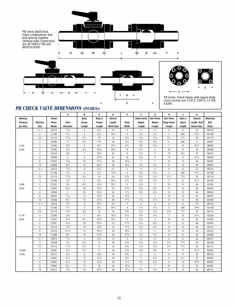
PB CHECK VALVE DIMENSIONS (INCHES):A B C D E F G H J K
Working Check Body Body & Overall Check Valve Ball Valve Ball Valve Tube or Overall Matching
Pressure Nominal Valve Seat Group Flange Length, Body Nipple Nipple Body Group Spool Length, Ball/ Ball
psi (bar) Size Model Diameter Length Length Weld Ends Width Length Length Length Length Check Assy. Valve1/2 -1 CC013 13/16 4 61/2 12 3 4 4 4 6 22 BC013
2 CC108 11/2 4 61/2 141/2 4 51/4 51/4 5 N/A 191/2 BC108
21/2 CC113 113/16 51/2 10 16 53/4 51/4 51/4 51/2 71/2 29 BC113
3 CA200 2 41/2 75/8 16 41/2 53/4 53/4 5 N/A 21 BA201
3,705 3 CC206 23/8 5 81/2 161/2 61/4 53/4 53/4 7 8 311/2 BB209
(250) 4 CC302 31/8 61/2 101/4 191/2 8 61/2 5 10 8 36 BA305
4 CA310 35/8 7 103/4 20 8 61/2 5 10 81/2 37 BA312
6 CA500 5 9 131/4 22 10 61/2 5 12 9 411/2 BA503
8 CA701 71/16 12 177/8 26 141/4 7 7 15 12 53 BA701
10 CA808 81/2 15 201/2 30 163/4 71/2 71/2 17 12 59 BA9011/2 -1 CC013 13/16 4 61/2 12 3 4 4 4 6 22 BC013
2 CC108 11/2 4 61/2 141/2 4 51/4 51/4 5 N/A 191/2 BC108
21/2 CC113 113/16 51/2 10 16 53/4 51/4 51/4 51/2 71/2 29 BC113
3 CC206 23/8 5 81/2 161/2 61/4 53/4 53/4 7 8 311/2 BC204
5,000 4 CC302 31/8 61/2 101/4 191/2 8 61/2 5 10 8 36 BC302
(350) 6 CC401 41/16 10 153/4 23 111/2 61/2 61/2 11 12 46 BC401
6 CB500 5 10 153/4 23 111/2 61/2 61/2 13 12 48 BB503
8 CB701 71/16 12 181/8 26 141/4 7 7 15 12 53 BB701
10 CC808 81/2 15 213/8 30 171/4 71/2 71/2 17 12 59 BC8081/2 -1 CC013 13/16 4 61/2 12 3 4 4 4 6 22 BC013
2 CC108 11/2 4 61/2 141/2 4 51/4 51/4 5 N/A 191/2 BC108
21/2 CC113 113/16 51/2 10 16 53/4 51/4 51/4 51/2 71/2 29 BC113
6,170 3 CC206 23/8 5 81/2 161/2 61/4 53/4 53/4 7 8 311/2 BC204
(420) 4 CC302 31/8 61/2 101/4 191/2 8 61/2 5 10 8 36 BC302
6 CC401 41/16 10 153/4 23 111/2 61/2 61/2 11 12 46 BC401
6 CC410 45/8 10 153/4 23 111/2 61/2 61/2 13 12 48 BC412
8 CC613 613/16 12 181/8 26 141/4 7 7 15 12 53 BC613
10 CC808 81/2 15 213/8 30 171/4 71/2 71/2 17 12 59 BC8081/2 -1 CD013 13/16 4 61/2 12 3 4 4 4 6 22 BD013
2 CD108 11/2 51/2 11 16 67/8 51/4 51/4 51/2 71/2 29 BD108
21/2 CD113 113/16 51/2 11 16 67/8 51/4 51/4 51/2 71/2 29 BD113
10,000 3 CD201 21/16 51/2 11 16 67/8 51/4 43/4 7 9 311/2 BD202
(700) 3 CD212 23/4 8 133/4 18 83/4 5 5 8 9 35 BD210
4 CD301 31/16 8 133/4 18 83/4 5 51/2 9 91/2 37 BD302
6 CD401 41/16 10 153/4 23 111/2 61/2 61/4 12 13 473/4 BD402
8 CD601 61/16 13 20 26 141/4 7 7 15 12 53 BD601
10 CD712 73/4 15 213/8 30 171/4 71/2 71/2 17 12 59 BD712
PB Series Ball/CheckValve combinations thatbolt directly together(without tube connection)are: BC108/CC108 andBA201/CA200.
PB Series Check Valves with square bodycross-section are: CC013, CD013, CC108,CA200.
13

PIPER VALVE SYSTEMS Distributed By Rotating Right Inc.
8309 Wagner Road Edmonton, AB T6E 5A7
Phone: 1-780-485-2010 Fax: 1-780-485-1938
e-mail: [email protected]
Litho in U.S.A. 2/99
Reverse Circulating Manifold3” 5,000 psi CWP
Production Station Manifold
14