Embed Size (px)
Citation preview
� ला� ़मा अनुसंधान सं� थानINSTITUTE FOR PLASMA RESEARCH
परमाणु ऊजा� �वभाग, भारत सरकार का एक सहायता �ा� तसं�थान
An Aided Institute of Department of Atomic Energy,
Government of India
इ��दरा पुल के पास, भाट, गांधीनगर – 382 428 भारतदरूभाष: (079) 2396 2020/2021/2028
फै�स: 91-079-23962277
वेब: www.ipr.res.in
NEAR INDIRA BRIDGE, BHATDIST. GANDHINAGAR - 382 428 (INDIA)
Phone: (079) 2396 2020/2021/2028 Fax : 91-079-23962277
Web : www.ipr.res.in
ENQUIRY
ENQUIRY NO : IPR/EQL/17-18/568
Date : 28-02-2018
Due on : 05-04-2018 by 1:00 PM IST
Please send your offer in sealed envelope specifying Enquiry No, Date & Due Date, ALONG
WITH your credentials for the following items:
Important Note:
Please note that e-mail quotations are not acceptable however you may send your queries (if
any) to [email protected]
Please ensure your sealed quotation reaches this office not later than above mentioned due
date and time.
Kindly go through the following documents properly before quoting which are available on the
IPR web portal i.e., http://www.ipr.res.in/documents/tender_terms.html / attached herewith.
1) Instructions to the bidders & Terms and conditions (refer Form No: IPR-LP-01.V3)
2) Bidding format
GST for Goods and Services (IGST/CGST/SGST TAX BENEFITS): Please refer clause no: 8
of Form No: IPR-LP-01.V3
QUOTATION SHOULD BE ADDRESSED TO PURCHASE OFFICER ONLY
Sr No
Description Quantity
1 Mechanical design, fabrication, testing and supply of 2-stream (helium/2-
phase N2) vacuum-brazed Al-plate-fin heat exchanger (HE2)
1.0 Nos.
Note: 80% of order value will be made against delivery of material
at IPR site and its verification by IPR representative. Balance
20% will be made within 30 days from the date of acceptance
and on receipt of Performance Bank Guarantee for 10% of
the order value from SBI/nationalized/scheduled bank
(Scheduled banks acceptable to IPR are Axis Bank, HDFC
Bank, ICICI Bank and IDBI Bank) valid throughout the
warranty period.
Please quote with complete technical details (Technical
compliance sheet and product data sheet).
Encl: As per attachment. Sd/-
Mr. D. Ramesh
PDF processed with CutePDF evaluation edition www.CutePDF.com

Purchase Officer-II
Information to Vendors: We are working towards a single platform for our future
requirement. Hence, please refer IPR website i.e,
http://www.ipr.res.in/documents/tendersenq.html for our future requirement.
TECHNICAL SPECIFICATION
Mechanical design, fabrication, testing and supply of
2-stream (helium/2-phase N2) vacuum-brazed Al-
plate-fin heat exchanger (HE2)
2
Contents Page Number
Introduction ........................................................................................................................................... 3 1.
Eligibility criteria for vendor to submit the Quotation ........................ Error! Bookmark not defined. 2.
Scope ..................................................................................................................................................... 3 3.
3.1 Design ........................................................................................................................................... 3
3.2 Documents for design approval .................................................................................................... 3
3.3 Manufacturing ............................................................................................................................... 4
3.4 Tests, inspection and acceptance criteria ...................................................................................... 4
Shop test and acceptance criteria .......................................................................................... 4 3.4.1
Site test and acceptance criteria ............................................................................................ 4 3.4.2
Inspection by IPR .................................................................................................................. 5 3.4.3
3.5 Documentations to supply ............................................................................................................. 5
3.6 Packing and Forwarding ............................................................................................................... 5
Specification of material of different parts ........................................................................................... 5 4.
Heat exchanger dimensions, drawings and configuration details ......................................................... 6 5.
5.1 Dimensions and configuration ...................................................................................................... 6
5.2 Drawings: ...................................................................................................................................... 9
3
Introduction 1.Thermo-hydraulic design of liquid nitrogen-cooled compact plate-fin heat exchanger, to be used
in the helium refrigerator/liquefier (HRL) plant, has been done. This, initially will also be used in
the turbine test facility to cool helium gas from about 80 to about 30 K. This will be, later, after
turbine tests, used in the helium plant for cooling of helium gas from ~100 K to ~80 K using LN2.
Heat exchanger is named as HE2. This will be installed vertically, so that, Liquid N2 (LN2) will
enter from bottom of it and vapor N2 (VN2) will come out at top of it. This will be tested at low
temperature at IPR. Relevant design information, drawing and dimensions have been included in
this document. Based on these information, supplier shall do mechanical design and supplier may
change overall dimensions of the heat exchanger except the fin parameters, layer arrangement,
width and length of thermal zone. The changes, due to mechanical design, are unlikely to change
the thermo-hydraulic performance of the heat exchanger. Before going for manufacturing,
supplier must get the design and drawings approved from IPR. The details of the scope and
technical specifications with drawings are given in this document.
Scope 2.
This purchase order covers mechanical design, documentation, manufacturing, testing,
inspection, packing, forwarding, supply and guarantee/warrantee of one 2-stream (2-phase
N2/helium) vacuum brazed aluminum plate fin compact heat exchanger. More details are given
as follows.
2.1 Design
The supplier shall carry out the entire mechanical design of this heat exchanger and the supplier
shall be responsible for the mechanical performance as well as mechanical stability of this whole
unit. The design shall be carried out for the design data given in Table-1.The mechanical design
of heat exchanger shall be done as per code of ASME section VIII Div-I and ALPEMA. As an
additional requirement in the view of cryogenic service, the supplier may include any other
relevant code that will be used in designing. This exchanger shall be provided with suitable
support structure handling, assembly and installation inside the vacuum chamber and it shall be
approved from IPR before manufacturing. Drawings are attached with part numbering and
names.
2.2 Documents for design approval
Following documents shall be submitted for the approval of the purchaser prior to the fabrication:
1. Material test report: Mill test certificate or random sampling and testing at NABL certified Labs. 2. Brazing and welding procedure and qualification certificate along with the brazing operator and
welder qualification certificate as per ASME section-IX. 3. Pneumatic and helium leak test procedure. 4. Mechanical design and fabrication drawings with stacking arrangement. 5. Quality assurance plan clearly indicating material procurement, manufacturing/fabrication stages,
inspection and testing along with different hold points and witness points.
4
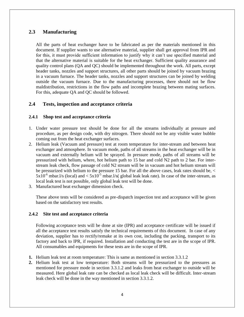
2.3 Manufacturing
All the parts of heat exchanger have to be fabricated as per the materials mentioned in this
document. If supplier wants to use alternative material, supplier shall get approval from IPR and
for this, it must provide sufficient information to justify why it can’t use specified material and
that the alternative material is suitable for the heat exchanger. Sufficient quality assurance and
quality control plans (QA and QC) should be implemented throughout the work. All parts, except
header tanks, nozzles and support structures, all other parts should be joined by vacuum brazing
in a vacuum furnace. The header tanks, nozzles and support structures can be joined by welding
outside the vacuum furnace. Due to the manufacturing processes, there should not be flow
maldistribution, restrictions in the flow paths and incomplete brazing between mating surfaces.
For this, adequate QA and QC should be followed.
2.4 Tests, inspection and acceptance criteria
Shop test and acceptance criteria 2.4.1
1. Under water pressure test should be done for all the streams individually at pressure and
procedure, as per design code, with dry nitrogen. There should not be any visible water bubble
coming out from the heat exchanger surfaces.
2. Helium leak (Vacuum and pressure) test at room temperature for inter-stream and between heat
exchanger and atmosphere. In vacuum mode, paths of all streams in the heat exchanger will be in
vacuum and externally helium will be sprayed. In pressure mode, paths of all streams will be
pressurized with helium, where, hot helium path to 15 bar and cold N2 path to 2 bar. For inter-
stream leak check, flow passage of cold N2 stream will be in vacuum and hot helium stream will
be pressurized with helium to the pressure 15 bar. For all the above cases, leak rates should be, <
5x10⁻⁶ mbar.l/s (local) and < 5x10⁻⁵ mbar.l/s( global leak leak rate). In case of the inter-stream, as
local leak test is not possible, only global leak test will be done.
3. Manufactured heat exchanger dimension check.
These above tests will be considered as pre-dispatch inspection test and acceptance will be given
based on the satisfactory test results.
Site test and acceptance criteria 2.4.2
Following acceptance tests will be done at site (IPR) and acceptance certificate will be issued if
all the acceptance test results satisfy the technical requirements of this document. In case of any
deviation, supplier has to rectify/remake at its own cost, including the packing, transport to its
factory and back to IPR, if required. Installation and conducting the test are in the scope of IPR.
All consumables and equipments for these tests are in the scope of IPR.
1. Helium leak test at room temperature: This is same as mentioned in section 3.3.1.2
2. Helium leak test at low temperature: Both streams will be pressurized to the pressures as
mentioned for pressure mode in section 3.3.1.2 and leaks from heat exchanger to outside will be
measured. Here global leak rate can be checked as local leak check will be difficult. Inter-stream
leak check will be done in the way mentioned in section 3.3.1.2.
5
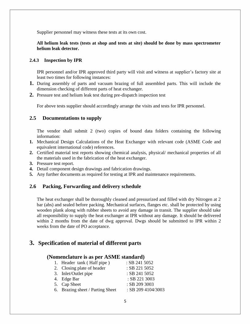
Supplier personnel may witness these tests at its own cost.
All helium leak tests (tests at shop and tests at site) should be done by mass spectrometer
helium leak detector.
Inspection by IPR 2.4.3
IPR personnel and/or IPR approved third party will visit and witness at supplier’s factory site at
least two times for following instances:
1. During assembly of parts and vacuum brazing of full assembled parts. This will include the
dimension checking of different parts of heat exchanger.
2. Pressure test and helium leak test during pre-dispatch inspection test
For above tests supplier should accordingly arrange the visits and tests for IPR personnel.
2.5 Documentations to supply
The vendor shall submit 2 (two) copies of bound data folders containing the following
information: 1. Mechanical Design Calculations of the Heat Exchanger with relevant code (ASME Code and
equivalent international code) references.
2. Certified material test reports showing chemical analysis, physical/ mechanical properties of all
the materials used in the fabrication of the heat exchanger.
3. Pressure test report.
4. Detail component design drawings and fabrication drawings.
5. Any further documents as required for testing at IPR and maintenance requirements.
2.6 Packing, Forwarding and delivery schedule
The heat exchanger shall be thoroughly cleaned and pressurized and filled with dry Nitrogen at 2
bar (abs) and sealed before packing. Mechanical surfaces, flanges etc. shall be protected by using
wooden plank along with rubber sheets to avoid any damage in transit. The supplier should take
all responsibility to supply the heat exchanger at IPR without any damage. It should be delivered
within 2 months from the date of dwg approval. Dwgs should be submitted to IPR within 2
weeks from the date of PO acceptance.
Specification of material of different parts 3.
(Nomenclature is as per ASME standard) 1. Header tank ( Half pipe ) : SB 241 5052
2. Closing plate of header : SB 221 5052
3. Inlet/Outlet pipe : SB 241 5052
4. Edge Bar : SB 221 3003
5. Cap Sheet : SB 209 3003
6. Brazing sheet / Parting Sheet : SB 209 4104/3003
6
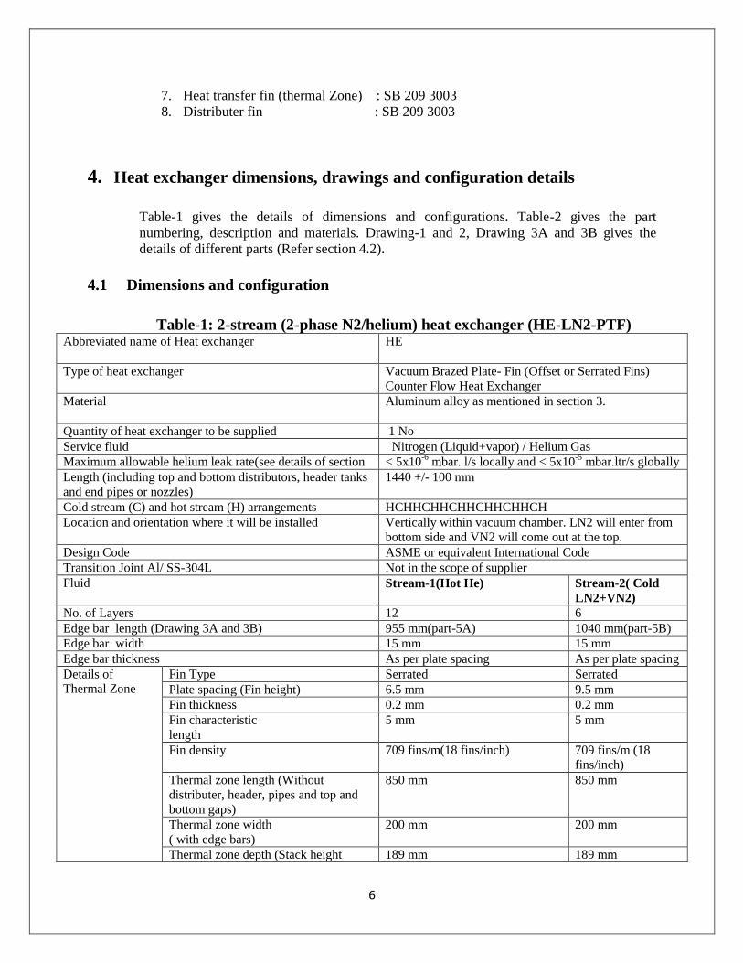
7. Heat transfer fin (thermal Zone) : SB 209 3003
8. Distributer fin : SB 209 3003
Heat exchanger dimensions, drawings and configuration details 4.
Table-1 gives the details of dimensions and configurations. Table-2 gives the part
numbering, description and materials. Drawing-1 and 2, Drawing 3A and 3B gives the
details of different parts (Refer section 4.2).
4.1 Dimensions and configuration
Table-1: 2-stream (2-phase N2/helium) heat exchanger (HE-LN2-PTF)
Abbreviated name of Heat exchanger
HE
Type of heat exchanger
Vacuum Brazed Plate- Fin (Offset or Serrated Fins)
Counter Flow Heat Exchanger
Material Aluminum alloy as mentioned in section 3.
Quantity of heat exchanger to be supplied 1 No
Service fluid Nitrogen (Liquid+vapor) / Helium Gas
Maximum allowable helium leak rate(see details of section < 5x10⁻⁶
mbar. l/s locally and < 5x10⁻⁵
mbar.ltr/s globally
Length (including top and bottom distributors, header tanks
and end pipes or nozzles)
1440 +/- 100 mm
Cold stream (C) and hot stream (H) arrangements HCHHCHHCHHCHHCHHCH
Location and orientation where it will be installed Vertically within vacuum chamber. LN2 will enter from
bottom side and VN2 will come out at the top.
Design Code ASME or equivalent International Code
Transition Joint Al/ SS-304L Not in the scope of supplier
Fluid Stream-1(Hot He) Stream-2( Cold
LN2+VN2)
No. of Layers 12 6
Edge bar length (Drawing 3A and 3B) 955 mm(part-5A) 1040 mm(part-5B)
Edge bar width 15 mm 15 mm
Edge bar thickness As per plate spacing As per plate spacing
Details of
Thermal Zone
Fin Type Serrated Serrated
Plate spacing (Fin height) 6.5 mm 9.5 mm
Fin thickness 0.2 mm 0.2 mm
Fin characteristic
length
5 mm 5 mm
Fin density 709 fins/m(18 fins/inch) 709 fins/m (18
fins/inch)
Thermal zone length (Without
distributer, header, pipes and top and
bottom gaps)
850 mm 850 mm
Thermal zone width
( with edge bars)
200 mm 200 mm
Thermal zone depth (Stack height 189 mm 189 mm
7
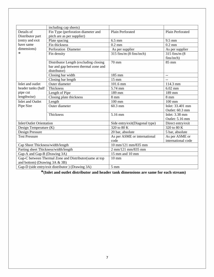
including cap sheets)
Details of
Distributor part
(entry and exit
have same
dimensions)
*
Fin Type (perforation diameter and
pitch are as per supplier)
Plain Perforated Plain Perforated
Plate spacing 6.5 mm 9.5 mm
Fin thickness 0.2 mm 0.2 mm
Perforation Diameter As per supplier As per supplier
Fin density 315 fins/m (8 fins/inch) 315 fins/m (8
fins/inch)
Distributor Length (excluding closing
bar and gap between thermal zone and
distributor)
70 mm 85 mm
Closing bar width 185 mm --
Closing bar length 15 mm --
Inlet and outlet
header tanks (half
pipe cut
lengthwise)
Outer diameter 101.6 mm 114.3 mm
Thickness 5.74 mm 6.02 mm
Length of Pipe 189 mm 189 mm
Closing plate thickness 8 mm 8 mm
Inlet and Outlet
Pipe Size
Length 100 mm 100 mm
Outer diameter 60.3 mm Inlet: 33.401 mm
Outlet: 60.3 mm
Thickness 5.16 mm Inlet: 3.38 mm
Outlet: 5.16 mm
Inlet/Outlet Orientation Side entry/exit(Diagonal type) Direct entry/exit
Design Temperature (K) 320 to 80 K 320 to 80 K
Design Pressure 20 bar, absolute 5 bar, absolute
Test Pressure As per ASME or international
code
As per ASME or
international code
Cap Sheet Thickness/width/length 10 mm/121 mm/835 mm
Parting sheet Thickness/width/length 2 mm/121 mm/835 mm
Gap-A and Gap-B (Drawing 3A) 15 mm and 10 mm
Gap-C between Thermal Zone and Distributor(same at top
and bottom) (Drawing 3A & 3B)
10 mm
Gap-D (side entry/exit distributor ) (Drawing 3A) 5 mm
*(Inlet and outlet distributor and header tank dimensions are same for each stream)

8
Table-2: Part No. (See drawing-1 to 3) with names and materials
CONFIDENTIALITY AND NONDISCLOSURE AGREEMENT
IPR’s this heat exchanger design information should not be used for any other purpose than what
is mentioned in this technical specification without consent of IPR.
No. of
different
Parts.
Names of different Part Material
1 Cap Sheet SB 209 3003
2 Thermal Zone fins (Heat transfer fins) SB 209 3003
3 Top distributor (fins) SB 209 3003
4 Bottom distributor (fins) SB 209 3003
5 Edge bar SB 221 3003
5A Edge bar (Hot layer) SB 221 3003
5B Edge bar (Cold layer) SB 221 3003
6 Brazing sheet/Parting Sheet/Brazing Sheet SB 209 4104/3003/4104
7,8,9,10 Header Tank SB 241 5052
11 Inlet and Outlet Pipes SB 241 5052
12 End Edge bar SB 221 3003
13 Closing plate of header tank SB 221 5052
9
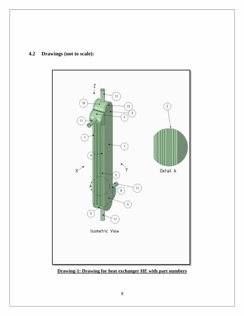
4.2 Drawings (not to scale):
Drawing-1: Drawing for heat exchanger HE with part numbers
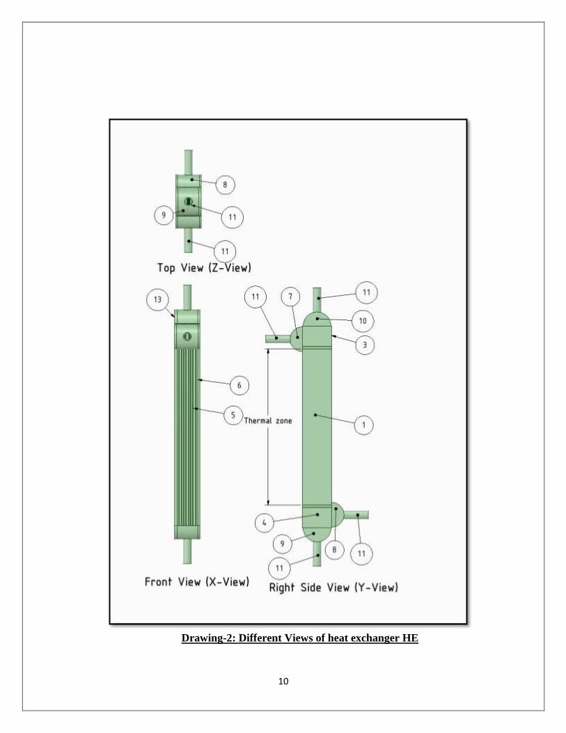
10
Drawing-2: Different Views of heat exchanger HE
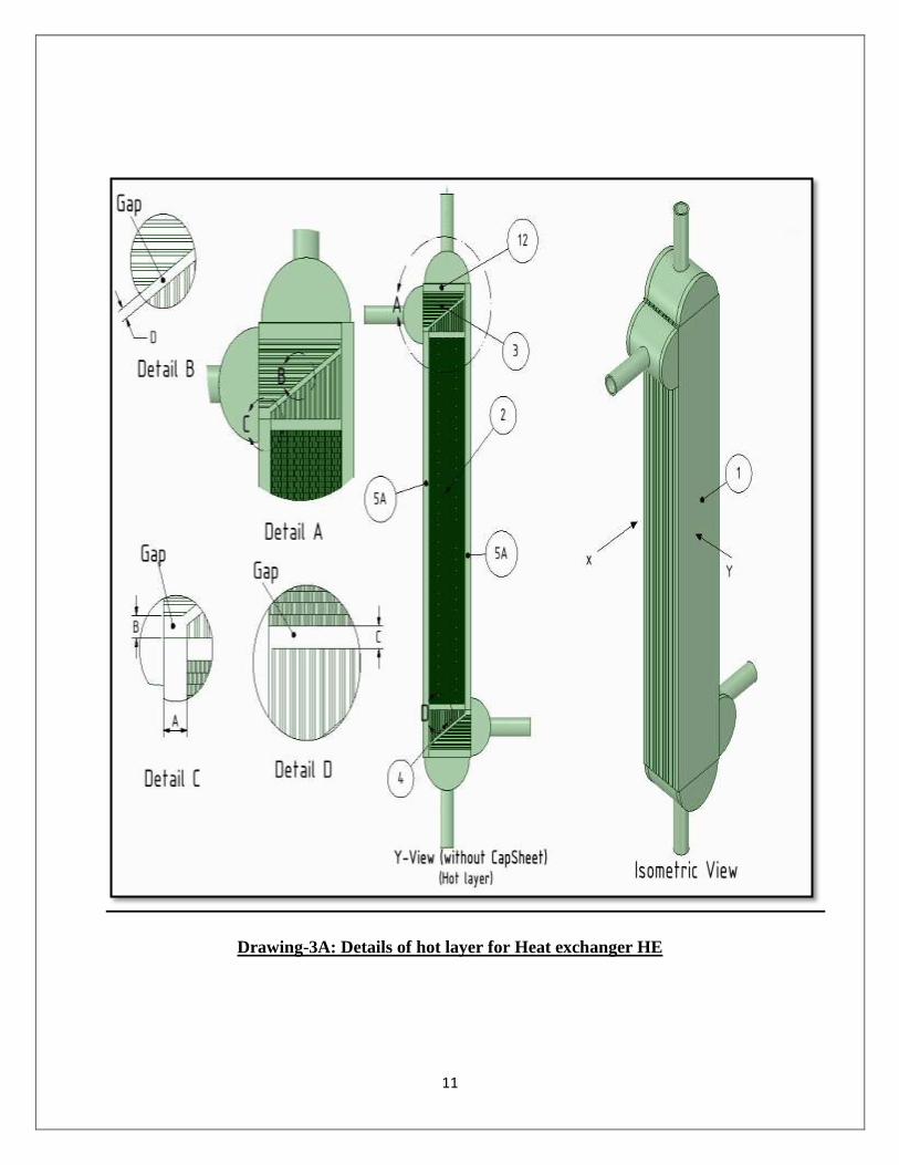
11
Drawing-3A: Details of hot layer for Heat exchanger HE
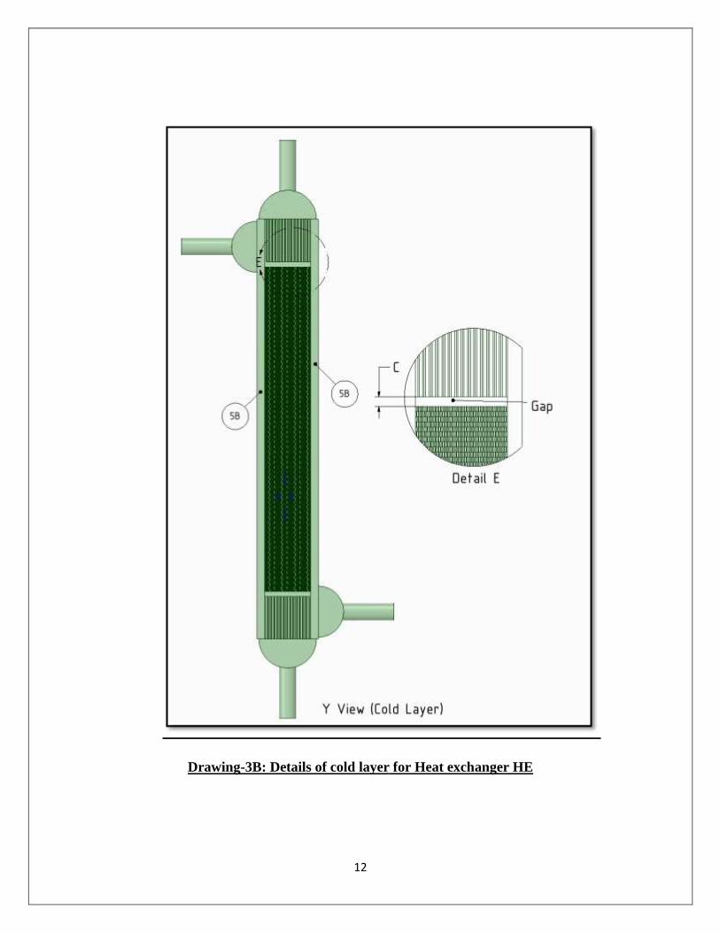
12
Drawing-3B: Details of cold layer for Heat exchanger HE


![IIM Bill 2015mhrd.gov.in/sites/upload_files/mhrd/files/upload... · अनुवाद] भारतीय प्रबंध संथान िवधेयक, 2015 कितपय](https://img.pdfslide.us/doc/110x75/5f0a897c7e708231d42c1ed6/iim-bill-aaaaaa-aaaaaa-aaaaaa-aaaaa.jpg)