Embed Size (px)
Citation preview
1
DEVELOPMENT OF A DEDICATED SOFTWARE TOOL FOR THE GLOBAL THERMOMECHANICAL ANALYSIS OF PLATE-FIN HEAT
EXCHANGERS
*Johan Dib¹, François Bilteryst², Jean-Louis Batoz³ and Ivan Lewon¹ ¹ Fives Cryo,
R&D department 25 bis rue du fort
F-88194 Golbey Cedex [email protected] http://www.fivesgroup.com
² GIP-InSIC, Laboratoire LEMTA 27, rue d’Hellieule
F-88100 St-Dié-des-Vosges [email protected]
www.insic.fr
³ UTC, Départt. GSU, Centre P. Guillaumat
Rue du Docteur Schweitzer F-60200 Compiègne
[email protected] www.utc.fr
Key words: Plate-fin heat exchanger, homogenization, finite element, dedicated software tool
Abstract. In this paper we describe the work [2] of developing a software tool based on the linear thermo-mechanical FE modeling of the heat exchanger using homogenization techniques. 1 INTRODUCTION
Fives Cryo, implanted in Golbey (Vosges, France), is one of the major manufacturers of heat exchangers for gas processing industries. The company is continuously developing its know-how in design, manufacture, insulation, installation and maintenance of brazed aluminium plate fin heat exchangers (figure 1). In the last 40 years, a large variety of cryogenic processes have used this type of heat exchangers which provides excellent heat exchanges and mechanical characteristics at low temperatures. Brazed aluminium plate-fin heat exchangers are used in : process plants to separate feed gas into its constituents like applications in cryogenic separation and air liquefaction, natural gas processing and liquefaction, petrochemicals production and gas treatment, and large refrigeration systems…
Different types of corrugated fins
Figure 1: A typical multi-stream brazed aluminum plate-fin heat exchanger and its general description A general description of a multi-stream brazed aluminum plate-fin heat exchanger is
presented in reference [1] and figure 1. This type of heat-exchangers is mainly based on the stacking of different layers. Each layer is made by corrugated fins (corrugated aluminum sheets) disposed between two parting sheets (flat plates) and closed by side bars. Openings in side bars assure fluid inlets and outlets. Layers are designed according to specific conditions of operating pressures, temperatures and fluids characteristics, that can be different from one layer to another.
2
2 GLOBAL MODELING OF THE HEAT EXCHANGER
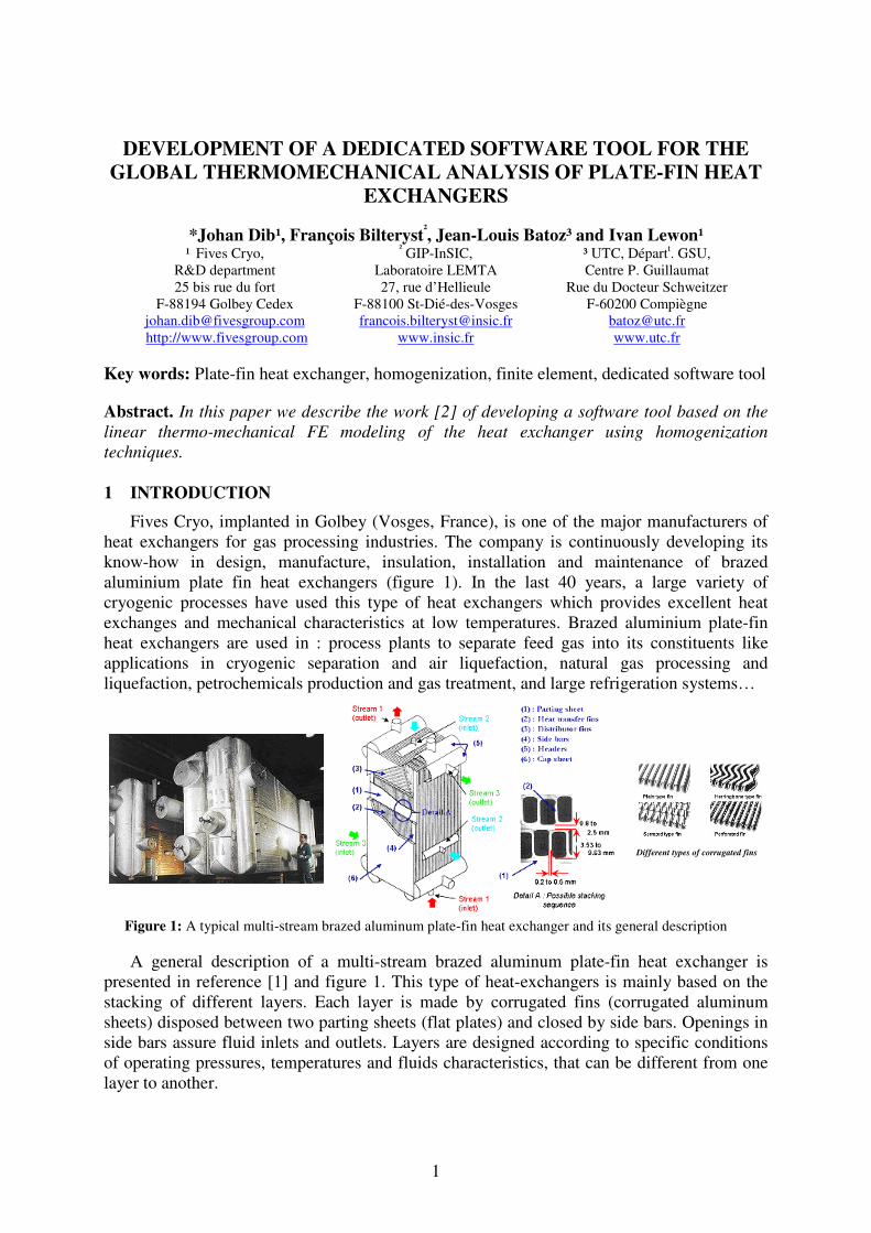
Since a complete FEM model would lead to several billions of structural elements (solid), we propose a 3D FEM model based on layer by layer homogenization techniques to obtain the equivalent (effective) stress-strain relations and thermal load vectors of the corrugated fins brazed with the parting sheets [2]. So a methodology for modeling the heat exchanger constituted by stacking of sheets and different brazed fins with different orientations, pressure and temperature loading is adopted (figure 2). Since the stacking sequence is considered as aleatory, we seek to determine a characteristic range of the effective behavior limited by a “rigid” and a “soft” medium behavior which are respectively determined by a partially periodic mechanical approach (PPMH) and a partially periodic kinematical approach (PPKH). These techniques are based on classical Hill-Mandel [3] methods where periodicity and fins orientation in each layer are taken into consideration. Other classical techniques can be applied to the identical layer stacking (e.g. asymptotic method [4]) where periodicity is considered in all directions.
Figure 2: General homogenization approach for individual layer.
So in order to facilitate the layer-by-layer homogenization of the heat exchanger, a
homogenization tool (HomPass) is then developed. That enables us to establish a library of elements having equivalent behaviors to each layer of brazed fins and sheets. This library can also include the elementary equivalent loadings in pressure and temperature. That contributes also to the development of the final software tool (SiTEME) dedicated to the global thermo-mechanical study of the heat exchanger.
3 DEDICATED SOFTWARE TOOLS
The main structure of HomPass and SiTEME (figure 3) is based on the interfacing between external modules through batch files : we use GiD® [5] as pre-post processor, and Code_Aster® [6] for FEM calculations. Therefore, these software tools manage automatically industrial applications and ensure the connections with the specialized FEM modules. This gives also the advantage of updating continually external modules in order to optimize modeling performance. Beside, precise methods related to the global modeling and design are programmed inside these codes so that user can easily use them with other dedicated tools (e.g. thermal design software that generates 3D temperature pattern of the heat exchanger).
3
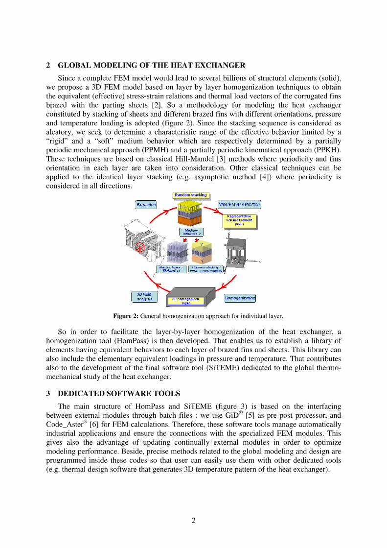
�Figure 3: Architecture of SiTEME software tool
�
�
�
�
�
�
�
�
�
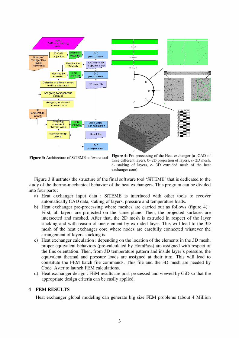
Figure 4: Pre-processing of the Heat exchanger (a- CAD of three different layers, b- 2D projection of layers, c- 2D mesh, d- staking of layers, e- 3D extruded mesh of the heat exchanger core)
Figure 3 illustrates the structure of the final software tool ‘SiTEME’ that is dedicated to the study of the thermo-mechanical behavior of the heat exchangers. This program can be divided into four parts :
a) Heat exchanger input data : SiTEME is interfaced with other tools to recover automatically CAD data, staking of layers, pressure and temperature loads.
b) Heat exchanger pre-processing where meshes are carried out as follows (figure 4) : First, all layers are projected on the same plane. Then, the projected surfaces are intersected and meshed. After that, the 2D mesh is extruded in respect of the layer stacking and with reason of one element by extruded layer. This will lead to the 3D mesh of the heat exchanger core where nodes are carefully connected whatever the arrangement of layers stacking is.
c) Heat exchanger calculation : depending on the location of the elements in the 3D mesh, proper equivalent behaviors (pre-calculated by HomPass) are assigned with respect of the fins orientation. Then, from 3D temperature pattern and inside layer’s pressure, the equivalent thermal and pressure loads are assigned at their turn. This will lead to constitute the FEM batch file commands. This file and the 3D mesh are needed by Code_Aster to launch FEM calculations.
d) Heat exchanger design : FEM results are post-processed and viewed by GiD so that the appropriate design criteria can be easily applied.
4 FEM RESULTS
Heat exchanger global modeling can generate big size FEM problems (about 4 Million
II – Passage P2
III – Passage P3
I – Passage P1
N° P1 P2 P3 17 16 15 14 13 12 11 10 9 8 7 6 5 4 3 2 1
a b
c
d e
4
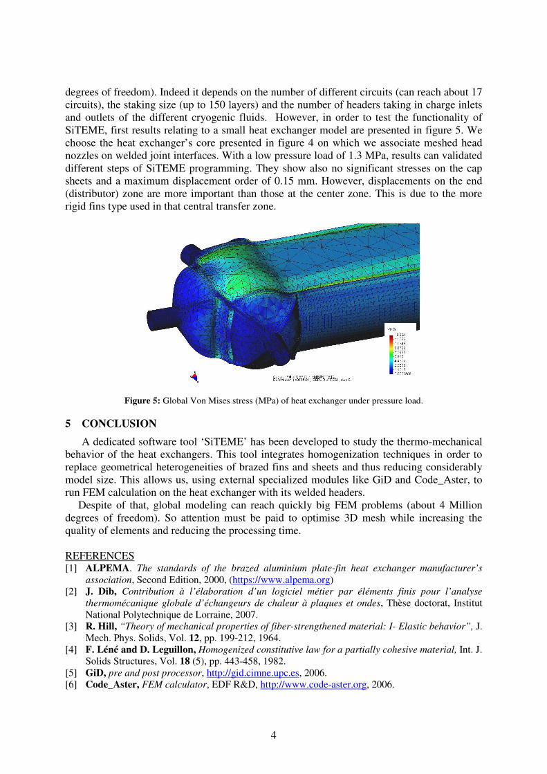
degrees of freedom). Indeed it depends on the number of different circuits (can reach about 17 circuits), the staking size (up to 150 layers) and the number of headers taking in charge inlets and outlets of the different cryogenic fluids. However, in order to test the functionality of SiTEME, first results relating to a small heat exchanger model are presented in figure 5. We choose the heat exchanger’s core presented in figure 4 on which we associate meshed head nozzles on welded joint interfaces. With a low pressure load of 1.3 MPa, results can validated different steps of SiTEME programming. They show also no significant stresses on the cap sheets and a maximum displacement order of 0.15 mm. However, displacements on the end (distributor) zone are more important than those at the center zone. This is due to the more rigid fins type used in that central transfer zone.
Figure 5: Global Von Mises stress (MPa) of heat exchanger under pressure load.
5 CONCLUSION
A dedicated software tool ‘SiTEME’ has been developed to study the thermo-mechanical behavior of the heat exchangers. This tool integrates homogenization techniques in order to replace geometrical heterogeneities of brazed fins and sheets and thus reducing considerably model size. This allows us, using external specialized modules like GiD and Code_Aster, to run FEM calculation on the heat exchanger with its welded headers.
Despite of that, global modeling can reach quickly big FEM problems (about 4 Million degrees of freedom). So attention must be paid to optimise 3D mesh while increasing the quality of elements and reducing the processing time.
REFERENCES [1] ALPEMA. The standards of the brazed aluminium plate-fin heat exchanger manufacturer’s
association, Second Edition, 2000, (https://www.alpema.org) [2] J. Dib, Contribution à l’élaboration d’un logiciel métier par éléments finis pour l’analyse
thermomécanique globale d’échangeurs de chaleur à plaques et ondes, Thèse doctorat, Institut National Polytechnique de Lorraine, 2007.
[3] R. Hill, “Theory of mechanical properties of fiber-strengthened material: I- Elastic behavior”, J. Mech. Phys. Solids, Vol. 12, pp. 199-212, 1964.
[4] F. Léné and D. Leguillon, Homogenized constitutive law for a partially cohesive material, Int. J. Solids Structures, Vol. 18 (5), pp. 443-458, 1982.
[5] GiD, pre and post processor, http://gid.cimne.upc.es, 2006. [6] Code_Aster, FEM calculator, EDF R&D, http://www.code-aster.org, 2006.