Embed Size (px)
Citation preview

- Element Quality
Element QualityElement QualityElement Quality
This chapter includes material from the book “Practical Finite This chapter includes material from the book “Practical Finite additional material added by Gareth Lee.additional material added by Gareth Lee.
Compatibility And MechanismsCompatibility And Mechanisms
odeling with a variety of element types provides many odeling with a variety of element types provides many mechanisms in your structural model. Incompatibilities arisemechanisms in your structural model. Incompatibilities arisecommon node, or element faces of solids are mismatched.common node, or element faces of solids are mismatched.
incomplete connectivity. Rigid elements which can model and/orincomplete connectivity. Rigid elements which can model and/oranother section.another section.
Spring ElementsSpring Elements
Spring elements are not really elements. The spring is a method ofSpring elements are not really elements. The spring is a method ofor to connect a single DOF to ground through a stiffness. If the DOFsor to connect a single DOF to ground through a stiffness. If the DOFsmechanism will occur. This mechanism will not cause a singularitymechanism will occur. This mechanism will not cause a singularitynowhere”. The following figure depicts aligned and misaligned springsnowhere”. The following figure depicts aligned and misaligned springs
Spring “Element” Spring “Element”
Shells To SolidsShells To Solids
The connection of shells to solids is useful in the transitionThe connection of shells to solids is useful in the transitionUnfortunately, solids do not support moments applied to nodes andUnfortunately, solids do not support moments applied to nodes andto solids. Running the model with irregular geometry will causeto solids. Running the model with irregular geometry will causeanswers which appear to be reasonable.answers which appear to be reasonable.
11
Element Quality And Checks -
Quality And ChecksQuality And ChecksQuality And Checks
Practical Finite Element Analysis”. It also has been reviewed and has Practical Finite Element Analysis”. It also has been reviewed and has
y opportunities to introduce numerical incompatibilities andy opportunities to introduce numerical incompatibilities andarise when the element degrees of freedom do not match at aarise when the element degrees of freedom do not match at a
mismatched. Mechanisms occur due to some forms of incompatibility ormismatched. Mechanisms occur due to some forms of incompatibility orand/or cause a number of interesting problems will be discussed in and/or cause a number of interesting problems will be discussed in
of directly coupling two degrees of freedom with a stiffness valueof directly coupling two degrees of freedom with a stiffness valueDOFs connected are not aligned in the global coordinate system, aDOFs connected are not aligned in the global coordinate system, a
ularity but will cause the introduction of a mysterious “torque fromularity but will cause the introduction of a mysterious “torque fromsprings.springs.
“Element” Alignment“Element” Alignment
from a compact solid structure to a more shell-like structure.from a compact solid structure to a more shell-like structure.and thus more innovative methods are required to connect shellsand thus more innovative methods are required to connect shells
cause the mesh to lock up and the hinges to be hidden, resulting incause the mesh to lock up and the hinges to be hidden, resulting in

- Element Quality
One accurate method of connecting shells to solids is depicted belOne accurate method of connecting shells to solids is depicted belconnection to the shell. Also note that local coordinate frames wouldconnection to the shell. Also note that local coordinate frames wouldbasic coordinate frame.basic coordinate frame.
Shells to SolidsShells to Solids
Beams To SolidsBeams To Solids
Beam to solid connections can be handled in a similar manner asBeam to solid connections can be handled in a similar manner asin at least two directions rather than in only the out-of-plane bending in at least two directions rather than in only the out-of-plane bending
22
Element Quality And Checks -
below. This method requires refinement in the solid mesh near thebelow. This method requires refinement in the solid mesh near theould be required if the normal direction does not line up with theould be required if the normal direction does not line up with the
o Solidso Solids
shell-to-solid connections. The moments will need to be coupled shell-to-solid connections. The moments will need to be coupled plane bending as in the shell-to-solid case.plane bending as in the shell-to-solid case.

- Element Quality
Beams Normal To ShellsBeams Normal To Shells
Beams connect well to shells except in the drilling direction. ThisBeams connect well to shells except in the drilling direction. Thisend of the beam as show below.end of the beam as show below.
Beam to ShellsBeam to Shells
Beam To Shell EdgeBeam To Shell Edge
An incompatibility exists when connecting beams to shells in the plane An incompatibility exists when connecting beams to shells in the plane
Beam to Shell
33
Element Quality And Checks -
This connection can be made by the addition of crank arms to theThis connection can be made by the addition of crank arms to the
o Shellso Shells
the plane of the shell as shown below.the plane of the shell as shown below.
o Shell Edge

- Element Quality
Beams Normal To ShellsBeams Normal To Shells
Beams connect well to shells except in the drilling direction. ThisBeams connect well to shells except in the drilling direction. Thisend of the beam as show below.end of the beam as show below.
Beam to ShellsBeam to Shells
Beam To Shell EdgeBeam To Shell Edge
An incompatibility exists when connecting beams to shells in the plane An incompatibility exists when connecting beams to shells in the plane
Beam to Shell Beam to Shell
230230
Element Quality And Checks -
This connection can be made by the addition of crank arms to theThis connection can be made by the addition of crank arms to the
o Shellso Shells
the plane of the shell as shown below.the plane of the shell as shown below.
o Shell Edgeo Shell Edge
230230
- Element Quality
General Element Quality ChecksGeneral Element Quality ChecksGeneral Element Quality Checks
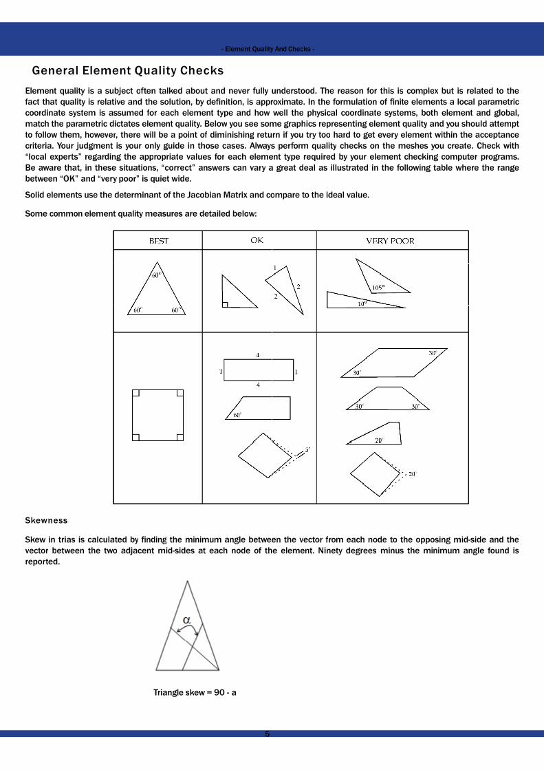
Element quality is a subject often talked about and never fully undeElement quality is a subject often talked about and never fully undefact that quality is relative and the solution, by definition, is approximafact that quality is relative and the solution, by definition, is approximacoordinate system is assumed for each element type and howcoordinate system is assumed for each element type and howmatch the parametric dictates element quality. Below you see somematch the parametric dictates element quality. Below you see someto follow them, however, there will be a point of diminishing returnto follow them, however, there will be a point of diminishing returncriteria. Your judgment is your only guide in those cases. Alwayscriteria. Your judgment is your only guide in those cases. Always“local experts” regarding the appropriate values for each element“local experts” regarding the appropriate values for each elementBe aware that, in these situations, “correct” answers can vary aBe aware that, in these situations, “correct” answers can vary abetween “OK” and “very poor” is quiet wide.between “OK” and “very poor” is quiet wide.
Solid elements use the determinant of the Jacobian Matrix and coSolid elements use the determinant of the Jacobian Matrix and co
Some common element quality measures are detailed below:Some common element quality measures are detailed below:
SkewnessSkewness
Skew in trias is calculated by finding the minimum angle betweenSkew in trias is calculated by finding the minimum angle betweenvector between the two adjacent mid-sides at each node of thevector between the two adjacent mid-sides at each node of thereported.reported.
Triangle skew = 90 - aTriangle skew = 90 - a
55
Element Quality And Checks -
understood. The reason for this is complex but is related to theunderstood. The reason for this is complex but is related to theroximate. In the formulation of finite elements a local parametricroximate. In the formulation of finite elements a local parametricwell the physical coordinate systems, both element and global,well the physical coordinate systems, both element and global,
some graphics representing element quality and you should attemptsome graphics representing element quality and you should attemptturn if you try too hard to get every element within the acceptanceturn if you try too hard to get every element within the acceptanceys perform quality checks on the meshes you create. Check withys perform quality checks on the meshes you create. Check with
element type required by your element checking computer programs.element type required by your element checking computer programs.a great deal as illustrated in the following table where the rangea great deal as illustrated in the following table where the range
compare to the ideal value. compare to the ideal value.
een the vector from each node to the opposing mid-side and theeen the vector from each node to the opposing mid-side and thethe element. Ninety degrees minus the minimum angle found isthe element. Ninety degrees minus the minimum angle found is

- Element Quality
Skew in quads is calculated by finding the minimum angle betwSkew in quads is calculated by finding the minimum angle betwdegrees minus the minimum angle found is reported.degrees minus the minimum angle found is reported.
Square skew = 90 - aSquare skew = 90 - a
The skew check is performed in the same fashion on all faces of threeThe skew check is performed in the same fashion on all faces of three
Aspect RatioAspect Ratio
Aspect ratio in two-dimensional elements is calculated by dividingAspect ratio in two-dimensional elements is calculated by dividingside of the element. The aspect ratio check is performed in the sameside of the element. The aspect ratio check is performed in the same
WarpageWarpage
Warpage in two-dimensional elements is calculated by splitting aWarpage in two-dimensional elements is calculated by splitting awhich the trias form. The quad is then split again, this time usingwhich the trias form. The quad is then split again, this time usingangle between the two planes which the trias form is then found.angle between the two planes which the trias form is then found.the element. Warpage in three-dimensional elements is performedthe element. Warpage in three-dimensional elements is performed
JacobianJacobian
The Jacobian ratio is a measure of the deviation of a given elementThe Jacobian ratio is a measure of the deviation of a given elementfrom -1.0 to 1.0, where 1.0 represents a perfectly shaped elementfrom -1.0 to 1.0, where 1.0 represents a perfectly shaped elementtype. The check is performed by mapping an ideal element in paramtype. The check is performed by mapping an ideal element in paramcoordinates. For example, the coordinates of the corners of ancoordinates. For example, the coordinates of the corners of an(1,1), and (-1,1).(1,1), and (-1,1).
The determinant of the Jacobian relates the local stretching of theThe determinant of the Jacobian relates the local stretching of theHyperMesh evaluates the determinant of the Jacobian matrix atHyperMesh evaluates the determinant of the Jacobian matrix atpoints), and reports the ratio between the smallest and the largestpoints), and reports the ratio between the smallest and the largest
Different solver codes use different patterns of integration points,Different solver codes use different patterns of integration points,formulations of the same element configuration. One method is asformulations of the same element configuration. One method is as
quad4 (2x2 points)quad4
tria3
(2x2 points)
(1 point)tria3
tetra4
(1 point)
(1 point)tetra4 (1 point)
quad8 (2x2 points)quad8
tria6
(2x2 points)
(4 point)tria6
tetra10
(4 point)
(4 point)tetra10
penta6
(4 point)
(3x2 points)penta6
hexa8
(3x2 points)
(2x2x2 points)hexa8 (2x2x2 points)
penta15 (3x2 points) penta15
hexa20
(3x2 points)
(2x2x2 points)hexa20 (2x2x2 points)
If the local stretching is the same at all of its Gauss points, thenIf the local stretching is the same at all of its Gauss points, thendistorted, the Jacobian value approaches zero. A Jacobian valuedistorted, the Jacobian value approaches zero. A Jacobian valueanalysis codes do not allow.analysis codes do not allow.
Both first and second order solid and plate elements are includedBoth first and second order solid and plate elements are includedhave a Jacobian value of 1.0.have a Jacobian value of 1.0.
66
Element Quality And Checks -
ween two lines joining opposite mid-sides of the element. Ninetyween two lines joining opposite mid-sides of the element. Ninety
three-dimensional elements.three-dimensional elements.
dividing the maximum length side of an element by the minimum lengthdividing the maximum length side of an element by the minimum lengthsame fashion on all faces of three-dimensional elements.same fashion on all faces of three-dimensional elements.
quad into two trias and finding the angle between the two planesquad into two trias and finding the angle between the two planessing the opposite corners and forming the second set of trias. Thesing the opposite corners and forming the second set of trias. The
The maximum angle found between the planes is the warpage ofThe maximum angle found between the planes is the warpage oformed in the same fashion on all faces of the element.ormed in the same fashion on all faces of the element.
element from an ideally shaped element. The Jacobian value rangeselement from an ideally shaped element. The Jacobian value rangeselement. The ideal shape for an element depends on the elementelement. The ideal shape for an element depends on the element
parametric coordinates onto the actual element defined in globalparametric coordinates onto the actual element defined in globalideal quad element in parametric coordinates are (-1,-1), (1,-1),ideal quad element in parametric coordinates are (-1,-1), (1,-1),
the parametric space required to fit it onto global coordinate space.the parametric space required to fit it onto global coordinate space.at each of the element’s integration points (also called Gaussat each of the element’s integration points (also called Gauss
largest.largest.
points, and the same solver may use different patterns for differentpoints, and the same solver may use different patterns for differentas follows:as follows:
then the Jacobian value equals 1.0. As the element becomes morethen the Jacobian value equals 1.0. As the element becomes morevalue of less than zero represents a concave element, which mostvalue of less than zero represents a concave element, which most
in this check; however, first order tria and tetra elements alwaysin this check; however, first order tria and tetra elements always

- Element Quality
2D Quality Checks2D Quality Checks2D Quality Checks
Ideal shape for quad elements – SquareIdeal shape for quad elements – Square
Ideal shape for triangular elements – Equilateral triangleIdeal shape for triangular elements – Equilateral triangle
Different quality parameters like skew, aspect ratio, included angles,Different quality parameters like skew, aspect ratio, included angles,element deviates from the ideal shape. A square means that all ofelement deviates from the ideal shape. A square means that all ofhas all angles at 60 with equal sides. Some of the quality checkshas all angles at 600 with equal sides. Some of the quality checksothers on side ratios and area (like aspect and stretch).others on side ratios and area (like aspect and stretch).
To reduce the solution time, elements are mapped to a local cooTo reduce the solution time, elements are mapped to a local cooinstead of using a single coordinate system (global). The effectiinstead of using a single coordinate system (global). The effectidistortion. Ideally all the nodes of a quad element should lie indistortion. Ideally all the nodes of a quad element should lie ingeometry profiles, that is not possible. The measure of the out of planegeometry profiles, that is not possible. The measure of the out of plane
The following are the general definitions of various quality checksThe following are the general definitions of various quality checksdiffer from software to software.differ from software to software.
Warp Angle: warp angle is the out of plane angle Warp Angle: warp angle is the out of plane angle
Ideal value = 00 (Acceptable < 100).Ideal value = 00 (Acceptable < 100).
Warp angle is not applicable for triangular elements.Warp angle is not applicable for triangular elements.
It is defined as the angle between the normals to two planesIt is defined as the angle between the normals to two planesThe maximum angle of the two possible angles is reported The maximum angle of the two possible angles is reported
Aspect: maximum element edge length / minimum element edge length Aspect: maximum element edge length / minimum element edge length
Ideal value = 1 (Acceptable < 5).Ideal value = 1 (Acceptable < 5).
SkewSkew
Ideal value = 0 (Acceptable < 450)Ideal value = 0 (Acceptable < 45 )
Skew for quadrilateral element = 900 minus the minimumSkew for quadrilateral element = 90 minus the minimumthe element (α).the element (α).
77
Element Quality And Checks -
angles, jacobian, stretch, etc. are the measures of how far a givenangles, jacobian, stretch, etc. are the measures of how far a givenof the angles are 90 with equal sides, while an equilateral triangleof the angles are 900 with equal sides, while an equilateral triangle
checks are based on angles (like skew and included angles), whilechecks are based on angles (like skew and included angles), while
coordinate system (individual for every element at the centroid),coordinate system (individual for every element at the centroid),ectiveness of this transformation is checked by the jacobian andectiveness of this transformation is checked by the jacobian and
in the same plane, but because of curvatures and complicatedin the same plane, but because of curvatures and complicatedplane angle is the warp angle.plane angle is the warp angle.
cks. Though the names sound the same, the exact definitions maycks. Though the names sound the same, the exact definitions may
planes formed by splitting the quad element along the diagonals.planes formed by splitting the quad element along the diagonals.ed as the warp angle.ed as the warp angle.
edge length edge length
minimum angle between the two lines joining the opposite mid-sides ofminimum angle between the two lines joining the opposite mid-sides of

- Element Quality
αα
Skew for triangular element = 900 minus the minimum angle beSkew for triangular element = 90 minus the minimum angle bebetween the two adjacent mid-sides at each node of the elementbetween the two adjacent mid-sides at each node of the element
JacobianJacobianIdeal value = 1.0 (Acceptable > 0.6 )Ideal value = 1.0 (Acceptable > 0.6 )
In simple terms, the jacobian is a scale factor arising becauseIn simple terms, the jacobian is a scale factor arising becauseare transformed from the global coordinates to local cooare transformed from the global coordinates to local cooanalysis times.analysis times.
DistortionDistortionIdeal value = 1.0 (Acceptable > 0.6)Distortion is defined as - | jacobian | * Area / AreaIdeal value = 1.0 (Acceptable > 0.6)Distortion is defined as - | jacobian | * Area / Area
LCS GCSLCS GCS
LCS – Local Coordinate systemLCS – Local Coordinate systemGCS – Global Coordinate systemGCS – Global Coordinate system
StretchStretchIdeal value: 1.0 (Acceptable > 0.2)Ideal value: 1.0 (Acceptable > 0.2)For quadrilateral elements stretch = L * √ 2 / dFor quadrilateral elements stretch = L * √ 2 / d
min maxmin max
LLmax L
RL
min
R
Stretch for triangular element = R * √ 12 / Lmax
Stretch for triangular element = R * √ 12 / Lmax
Included AnglesIncluded Angles
Skew is based on the overall shape of the element and it doesSkew is based on the overall shape of the element and it doesor triangular element. Included or interior angle check is or triangular element. Included or interior angle check is
Quad Ideal value = 900. (acceptable = 450 < θ <1350) Quad Ideal value = 90 . (acceptable = 45 < θ <135 )
Tria: Ideal value = 600 (acceptable = 200 < θ < 1200)Tria: Ideal value = 600 (acceptable = 200 < θ < 1200)
TaperTaper
Ideal value = 0 (acceptable < 0.5)Ideal value = 0 (acceptable < 0.5)
Taper = ∑ | (A – A ) / A |i avg avg
Taper = ∑ | (A – A ) / A |i avg avg
A =(A + A + A + A ) / 4avg 1 2 3 4
A =(A + A + A + A ) / 4avg 1 2 3 4
A3A3
Minimum Element LengthMinimum Element Length
This is a very important check for crash analysis (time step calculations).This is a very important check for crash analysis (time step calculations).feature length captured and the presence of any zero length element.feature length captured and the presence of any zero length element.
88
Element Quality And Checks -
αα
etween the lines from each node to the opposing mid-side andetween the lines from each node to the opposing mid-side and
because of the transformation of the coordinate system. Elementsbecause of the transformation of the coordinate system. Elementscoordinates (defined at the centroid of every element), for fastercoordinates (defined at the centroid of every element), for faster
GCSGCS
min
ddmax
does not take into account the individual angles of a quadrilateraldoes not take into account the individual angles of a quadrilateralis applied for individual angles.is applied for individual angles.
A4A4 A1A2A3
A1A2A3
calculations). It is also applied in general to check for the minimumcalculations). It is also applied in general to check for the minimumo length element.o length element.

- Element Quality
Chord DeviationChord Deviation
This helps in determining how well curvatures have been modeledThis helps in determining how well curvatures have been modeledelement edge to the curved surface. It is only applicable for linearelement edge to the curved surface. It is only applicable for linear
How To Improve The Quality Of Poor Elements?How To Improve The Quality Of Poor Elements?
1)Manual adjustment: This is done by translating the nodes manually 1)Manual adjustment: This is done by translating the nodes manually consumes lot of time and was the only technique available for yeaconsumes lot of time and was the only technique available for yea
2)Drag node: The user has to drag the nodes of the failing elements. 2)Drag node: The user has to drag the nodes of the failing elements. shows the effect of dragging the node on all the attached elements.shows the effect of dragging the node on all the attached elements.
3)Auto quality improvement programs: This is the latest option for3)Auto quality improvement programs: This is the latest option forquality improvement and a software program runs in the background quality improvement and a software program runs in the background
There is a word of caution for the use of auto mesh improvementThere is a word of caution for the use of auto mesh improvementJacobian/distortion improvement of 10 noded tetra meshes, somJacobian/distortion improvement of 10 noded tetra meshes, somconsiderable amount. This could cause visible kinks and distortionconsiderable amount. This could cause visible kinks and distortion
Apart from the above standard checks, the mesh model should alsoApart from the above standard checks, the mesh model should also
Other Checks For 2D MeshingOther Checks For 2D MeshingOther Checks For 2D Meshing
1) Element Free Edges - What is a free edge ?1) Element Free Edges - What is a free edge ?
Any single quad element has 4 free edges.Any single quad element has 4 free edges.
Two elementsTwo elements
In the case above, the middle edge is shared and is no longer a free edge. In the case above, the middle edge is shared and is no longer a free edge. the geometry outer edges / free edges. Any additional free edges the geometry outer edges / free edges. Any additional free edges
White line indicates freeWhite line indicates freeedge and unconnectednodes.nodes.
99
Element Quality And Checks -
modeled. It is defined as the distance between the mid node of anmodeled. It is defined as the distance between the mid node of anlinear elements.linear elements.
manually or remeshing in the poor mesh region. This methodmanually or remeshing in the poor mesh region. This methodears.ears.
elements. It works faster and the advantage is that it instantaneouslyelements. It works faster and the advantage is that it instantaneouslythe attached elements.the attached elements.
or quality improvement. The user has to submit the mesh foror quality improvement. The user has to submit the mesh foround to improve the elements quality automatically.ound to improve the elements quality automatically.
ement programs. For warpage improvement of 2D meshing andement programs. For warpage improvement of 2D meshing andsometimes the software moves the nodes off of the geometry by asometimes the software moves the nodes off of the geometry by ation of the geometry.tion of the geometry.
also be subjected to following the additional checks.also be subjected to following the additional checks.
free edge. For a real life FE model, free edges should match withfree edge. For a real life FE model, free edges should match withedges are an indication of unconnected nodes.edges are an indication of unconnected nodes.

- Element Quality
2) Duplicate Element2) Duplicate Element
Mistakes during operations like reflect or translate can result inMistakes during operations like reflect or translate can result inerror during the analysis but increase the stiffness of the model anderror during the analysis but increase the stiffness of the model andconsider a simple plate (thickness = 2 mm) subjected to a tensileconsider a simple plate (thickness = 2 mm) subjected to a tensileelements are duplicated. If the analysis is carried out then it will shelements are duplicated. If the analysis is carried out then it will sh
3) Duplicate Node3) Duplicate Node
Operations like copy, translate, orient, or reflect can result in duplicaOperations like copy, translate, orient, or reflect can result in duplica
In the above image there are duplicate nodes at the interface where In the above image there are duplicate nodes at the interface where highlighted in yellow.highlighted in yellow.
4) Shell Normal4) Shell Normal
Consider the following example.Consider the following example.
After deformation, the top surface of the cantilever beam is under After deformation, the top surface of the cantilever beam is under
For 2D meshing, a mid surface is extracted and an analysis is carried out on the For 2D meshing, a mid surface is extracted and an analysis is carried out on the the result plot (as shown below) corresponds to the mid surface, the the result plot (as shown below) corresponds to the mid surface, the
1010
Element Quality And Checks -
duplicate elements. These duplicate elements do not cause anyduplicate elements. These duplicate elements do not cause anyand results in smaller displacements and stresses. For example,and results in smaller displacements and stresses. For example,
ensile load. Assume that due to some meshing operation all theensile load. Assume that due to some meshing operation all theshow half the stress and displacement.show half the stress and displacement.
duplicate nodes at a common edge.duplicate nodes at a common edge.
where the mesh was reflected. The duplicate nodes arewhere the mesh was reflected. The duplicate nodes are
is under tension and the bottom is under compression.is under tension and the bottom is under compression.
carried out on the mid surface mesh. Now the question is, whether carried out on the mid surface mesh. Now the question is, whether the top surface, or the bottom surface?the top surface, or the bottom surface?
1010

- Element Quality
The shell element normal helps us in viewing the top or bottom sideThe shell element normal helps us in viewing the top or bottom sidesystem. The shell normal is the direction of the element normalsystem. The shell normal is the direction of the element normalassuming the element is oriented in the xy plane). For viewing stress,assuming the element is oriented in the xy plane). For viewing stress,bottom or Z1/Z2 indicating the positive and negative direction ofbottom or Z1/Z2 indicating the positive and negative direction ofmodel is oriented on the screen but as per the + Z axis orientationmodel is oriented on the screen but as per the + Z axis orientationby turning the element triad switch or shell normal vector display optionby turning the element triad switch or shell normal vector display option
Top side (or Z1) = + Z axis (along the direction of arrow as shown inTop side (or Z1) = + Z axis (along the direction of arrow as shown inBottom side (or Z2) = - Z axisBottom side (or Z2) = - Z axis
What Would Happen If The Shell Normals Are Not Aligned Properly?What Would Happen If The Shell Normals Are Not Aligned Properly?
From an analysis process point of view, there is no error. All ofFrom an analysis process point of view, there is no error. All ofpost processing when viewing the results for 2D elements, thepost processing when viewing the results for 2D elements, therecognizes is the shell normal orientation. It can show either therecognizes is the shell normal orientation. It can show either thefigure, one of the element’s shell normal is in the opposite directionfigure, one of the element’s shell normal is in the opposite directionelements (except the reverse shell normal orientation) show tensileelements (except the reverse shell normal orientation) show tensilestresses, as shown in the following figure. The beginner would intstresses, as shown in the following figure. The beginner would intboundary conditions, but an experienced engineer knows that thisboundary conditions, but an experienced engineer knows that this
How do you correct the shell normal’s alignment? The FEA softwHow do you correct the shell normal’s alignment? The FEA softwshell normals aligned in one direction).shell normals aligned in one direction).
5) Geometry Deviation5) Geometry Deviation
After the completion of meshing the geometry, the mesh and theAfter the completion of meshing the geometry, the mesh and themesh should not deviate from the geometry.mesh should not deviate from the geometry.
6) Delete Free / Temporary Nodes6) Delete Free / Temporary Nodes
Free nodes, if not deleted, result in rigid body motion. When theFree nodes, if not deleted, result in rigid body motion. When theelement with a very small stiffness to connect the free nodes withelement with a very small stiffness to connect the free nodes withthe analysis.
1111
Element Quality And Checks -
side stresses. Every element has an elemental (or local) coordinateside stresses. Every element has an elemental (or local) coordinatenormal (common practice is to represent the normal using the Z axis,normal (common practice is to represent the normal using the Z axis,
stress, commercial post processors provide options known as top /stress, commercial post processors provide options known as top /the shell normal. The top or bottom is not decided by how the FEthe shell normal. The top or bottom is not decided by how the FE
orientation of the elements. The Z axis could be displayed on the screenorientation of the elements. The Z axis could be displayed on the screenoption on.option on.
in figure below)in figure below)
Properly?Properly?
the calculations will be carried out properly. But at the time ofthe calculations will be carried out properly. But at the time ofsoftware does not understand tension or compression. What itsoftware does not understand tension or compression. What it
the stresses along the + Z axis or –Z axis. Suppose in the abovethe stresses along the + Z axis or –Z axis. Suppose in the abovedirection. While viewing the results on the bottom side (Z2) all thedirection. While viewing the results on the bottom side (Z2) all the
ensile (+) stresses and the odd element shows compressive (–)ensile (+) stresses and the odd element shows compressive (–)terpret from the following result that something is wrong with theterpret from the following result that something is wrong with the
this is due to an inconsistent shell normal.this is due to an inconsistent shell normal.
ware provides special commands for consistent shell normals (allware provides special commands for consistent shell normals (all
the geometry should be viewed together (mesh line option off). Thethe geometry should be viewed together (mesh line option off). The
the auto singularity option is turned on, the software uses a springthe auto singularity option is turned on, the software uses a springwith the parent structure. This results in a warning message duringwith the parent structure. This results in a warning message during
1111
- Element Quality
7) Renumber Nodes, Elements, Properties Etc. Before Expo7) Renumber Nodes, Elements, Properties Etc. Before Expo
Frequent import /export operations could lead to a very large numberFrequent import /export operations could lead to a very large numberread the file if the node/element IDs are greater than a specific limitread the file if the node/element IDs are greater than a specific limitetc.etc.
8) Observe Type, Family And Number Of Elements (Element8) Observe Type, Family And Number Of Elements (Element
The mesh should be checked carefully prior to the export operation,The mesh should be checked carefully prior to the export operation,type, family, numbers, etc. Sometimes due to a translator problem,type, family, numbers, etc. Sometimes due to a translator problem,elements, either the elements are not exported at all or the familyelements, either the elements are not exported at all or the familyetc.). Plot, trace lines, element free edges, and free faces, if any, shouldetc.). Plot, trace lines, element free edges, and free faces, if any, should
9) Check Mass ( actual mass vs. FE model mass9) Check Mass ( actual mass vs. FE model mass))
When a prototype or physical model of the component is available,When a prototype or physical model of the component is available,Adifference means that there are missing or additional components,Adifference means that there are missing or additional components,
10) Free-Free Run Or Dummy Linear Static Analysis10) Free-Free Run Or Dummy Linear Static Analysis
Before delivering the final mesh to the client, a free–free run shouldBefore delivering the final mesh to the client, a free–free run shouldassembly are properly connected to each other. In the case of a singleassembly are properly connected to each other. In the case of a singleboundary conditions should be carried out.boundary conditions should be carried out.
11) Request Your Colleague To Check The Model11) Request Your Colleague To Check The Model
Due to continually working on the same project, our mind tends toDue to continually working on the same project, our mind tends tomissing some of the points. It is a good practice to get it cross checmissing some of the points. It is a good practice to get it cross chec
Quality Checks For Tetra MeshesQuality Checks For Tetra Meshes
The ideal shape for a tetrahedron element is an equilateral tetrahedThe ideal shape for a tetrahedron element is an equilateral tetrahedcheck how far a given element deviates from the ideal shape.check how far a given element deviates from the ideal shape.
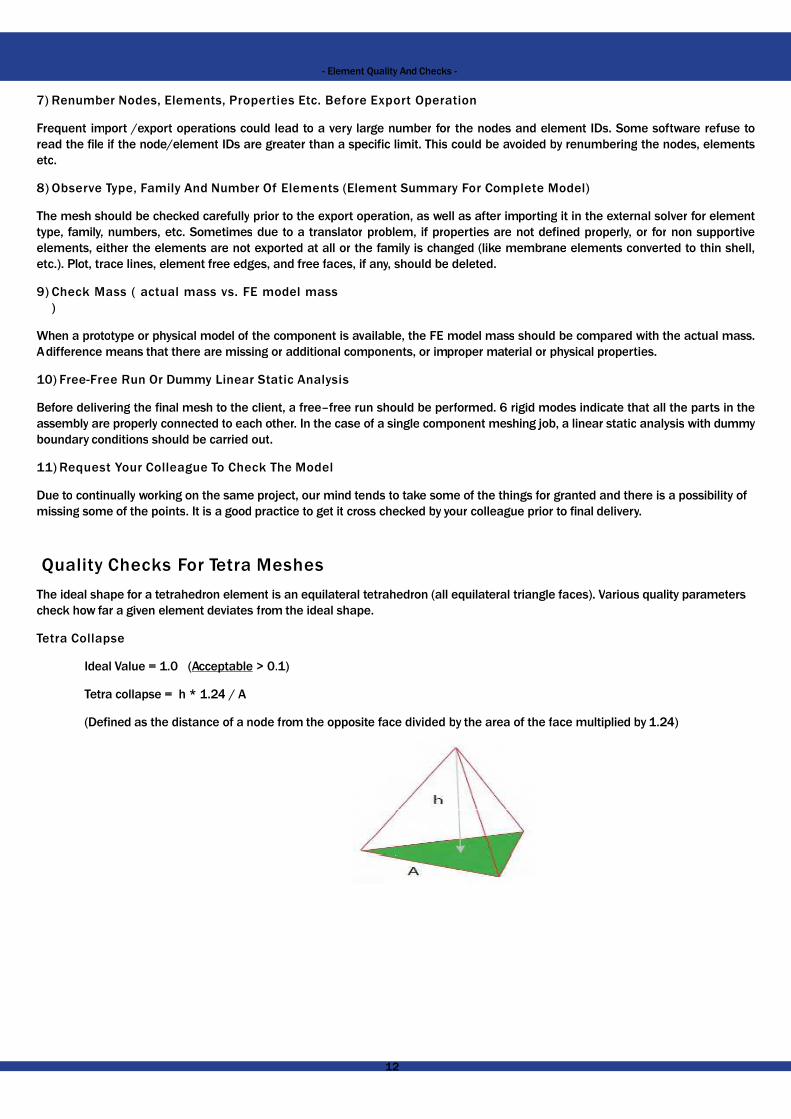
Tetra CollapseTetra Collapse
Ideal Value = 1.0 (Acceptable > 0.1)Ideal Value = 1.0 (Acceptable > 0.1)
Tetra collapse = h * 1.24 / ATetra collapse = h * 1.24 / A
(Defined as the distance of a node from the opposite face divided (Defined as the distance of a node from the opposite face divided
1212
Element Quality And Checks -
Export OperationExport Operation
number for the nodes and element IDs. Some software refuse tonumber for the nodes and element IDs. Some software refuse tolimit. This could be avoided by renumbering the nodes, elementslimit. This could be avoided by renumbering the nodes, elements
(Element Summary For Complete Model)(Element Summary For Complete Model)
operation, as well as after importing it in the external solver for elementoperation, as well as after importing it in the external solver for elementoblem, if properties are not defined properly, or for non supportiveoblem, if properties are not defined properly, or for non supportivefamily is changed (like membrane elements converted to thin shell,family is changed (like membrane elements converted to thin shell,
should be deleted.should be deleted.
ailable, the FE model mass should be compared with the actual mass.ailable, the FE model mass should be compared with the actual mass.ponents, or improper material or physical properties.ponents, or improper material or physical properties.
should be performed. 6 rigid modes indicate that all the parts in theshould be performed. 6 rigid modes indicate that all the parts in thesingle component meshing job, a linear static analysis with dummysingle component meshing job, a linear static analysis with dummy
o take some of the things for granted and there is a possibility ofo take some of the things for granted and there is a possibility ofchecked by your colleague prior to final delivery.checked by your colleague prior to final delivery.
trahedron (all equilateral triangle faces). Various quality parameters trahedron (all equilateral triangle faces). Various quality parameters
ace divided by the area of the face multiplied by 1.24)ace divided by the area of the face multiplied by 1.24)
1212

- Element Quality
Volumetric SkewVolumetric Skew
Create a sphere passing through the corner nodes of theCreate a sphere passing through the corner nodes of theideal and actual tetra elements.ideal and actual tetra elements.
Ideal value = 0 (Acceptable < 0.7)Ideal value = 0 (Acceptable < 0.7)
Volumetric Skew = (V - V ) / VVolumetric Skew = (Videal actual ideal
- V ) / V
StretchStretch
Ideal value = 1.0 (Acceptable > 0.2)Ideal value = 1.0 (Acceptable > 0.2)
Stretch = R * √24 / Lmax
Stretch = R * √24 / Lmax
R = Radius of largest possible sphere inside given tetra element.R = Radius of largest possible sphere inside given tetra element.
DistortionDistortion
Ideal value = 1.0 (Acceptable > 0.5)Ideal value = 1.0 (Acceptable > 0.5)
Distortion = | J | * Volm / VolmLCS GCSLCS GCS
LCS – Local Coordinate SystemLCS – Local Coordinate System
GCS – Global Coordinate SystemGCS – Global Coordinate System
JacobianJacobianIdeal value = 1.0 (Acceptable > 0.5)Ideal value = 1.0 (Acceptable > 0.5)
In simple terms, the Jacobian is a scale factor arising becauseIn simple terms, the Jacobian is a scale factor arising becausetransformed from global coordinates to local coordinates transformed from global coordinates to local coordinates
Other Checks For Tetra MeshesOther Checks For Tetra Meshes
1) Quality checks for 2D tria elements: Before converting trias to1) Quality checks for 2D tria elements: Before converting trias toshould be applied.should be applied.
2) Free edges: Conversion from tria to tetra is possible only when2) Free edges: Conversion from tria to tetra is possible only whenenclosing a volume.enclosing a volume.
3) T-connections: The mesh model should not contain any T-connection.3) T-connections: The mesh model should not contain any T-connection.
1313
Element Quality And Checks -
the tetra, fit an ideal (equilateral) tetra in it. Find the volume of thethe tetra, fit an ideal (equilateral) tetra in it. Find the volume of the
etra element.etra element.
because of the transformation of the coordinate system. Elements are because of the transformation of the coordinate system. Elements are es to reduce the solution time.es to reduce the solution time.
to tetras, all the quality checks as discussed for shell elementsto tetras, all the quality checks as discussed for shell elements
when there are no free edges. No free edges indicate the mesh is when there are no free edges. No free edges indicate the mesh is
connection.connection.
1313

- Element Quality
GeometryGeometry
No T-connection (correct
4)Consistent Shell normals: Before converting trias to tetras, the4)Consistent Shell normals: Before converting trias to tetras, theshell to solid conversion unless the normals of all the elementsshell to solid conversion unless the normals of all the elements
5) Geometry deviation: After the completion of meshing, the geom5) Geometry deviation: After the completion of meshing, the geomoption off). The mesh should not deviate from the geometry. Inoption off). The mesh should not deviate from the geometry. InJacobian on curved surfaces or fillets), sometimes nodes get translaJacobian on curved surfaces or fillets), sometimes nodes get transla
6) 2Dtriaelementsshouldbedeletedbeforethefinalsubmission: It’s 6) 2Dtriaelementsshouldbedeletedbeforethefinalsubmission: It’s tetra mesh in the final delivery.tetra mesh in the final delivery.
How To Improve Quality Of Tetra MeshHow To Improve Quality Of Tetra Mesh
Software provides auto algorithms/localized remeshing optionsSoftware provides auto algorithms/localized remeshing optionsof the elements but some might stay the same. For such elements,of the elements but some might stay the same. For such elements,translation of nodes. Unlike 2D shell elements, ‘dragging the nodestranslation of nodes. Unlike 2D shell elements, ‘dragging the nodes
Linear vs. Parabolic Tetra ElementsLinear vs. Parabolic Tetra Elements
Linear tetra elements are not recommended for structural analysisLinear tetra elements are not recommended for structural analysiselements.elements.
1414
Element Quality And Checks -
T-connection, not acceptableT-connection, not acceptable
Green elements should not be there in model
connection (correct mesh)
the shell normals should be corrected. Some software do not allowthe shell normals should be corrected. Some software do not allowelements are properly aligned.elements are properly aligned.
geometry as well as the mesh should be viewed together (mesh linegeometry as well as the mesh should be viewed together (mesh lineIn the process of quality improvement (in particular for distortion/In the process of quality improvement (in particular for distortion/
translated too far away from the geometry and is not acceptable.translated too far away from the geometry and is not acceptable.
It’s a common mistake to export 2D shell elements along withIt’s a common mistake to export 2D shell elements along with
for improving the mesh quality. These programs improve mostfor improving the mesh quality. These programs improve mostelements, the quality improvement is carried out using the manualelements, the quality improvement is carried out using the manualnodes is not an available option for 3-D elements.nodes is not an available option for 3-D elements.
analysis. They are very stiff and inaccurate compared to parabolicanalysis. They are very stiff and inaccurate compared to parabolic
1414

- Element Quality
If Linear Tetra Elements Are Not Recommended For StructuralIf Linear Tetra Elements Are Not Recommended For StructuralCommercial Fea Software?Commercial Fea Software?
1) For the structural analysis of very big assemblies, to reduce 1) For the structural analysis of very big assemblies, to reduce meshed with linear tetras.meshed with linear tetras.
2) For thermal analysis, a linear tetra is convenient as temperature 2) For thermal analysis, a linear tetra is convenient as temperature use of tetra 10 elements would unnecessarily increase dofs.use of tetra 10 elements would unnecessarily increase dofs.
CFD calculations are mostly based on linear elements.3) CFD calculations are mostly based on linear elements.Mold flow analysis
3)4) Mold flow analysis4)
Brick Mesh Quality ChecksBrick Mesh Quality ChecksBrick Mesh Quality Checks
The ideal shape for a brick element is a cube. Various quality criteriaThe ideal shape for a brick element is a cube. Various quality criteria
Warp AngleWarp Angle
Ideal value = 0 (Acceptable <300)Ideal value = 0 (Acceptable <300)
Warp angle is calculated on faces (quadrilateral) of a hexWarp angle is calculated on faces (quadrilateral) of a hexthe quad element.the quad element.
JacobianJacobian
Ideal value = 1.0 (Acceptable > 0.5)Ideal value = 1.0 (Acceptable > 0.5)
In simple language, the Jacobian is a scale factor arising In simple language, the Jacobian is a scale factor arising Elements are transformed from global to local coordinates Elements are transformed from global to local coordinates
DistortionDistortion
Ideal value = 1.0 (Acceptable > 0.5)Ideal value = 1.0 (Acceptable > 0.5)
Distortion = |J | * Volm / VolmLCS GCS
Distortion = |J | * Vol / VolLCS GCS
LCS – Local Coordinate SystemLCS – Local Coordinate System
GCS – Global Coordinate SystemGCS – Global Coordinate System
StretchStretch
Ideal value = 1.0 (Acceptable > 0.20); Stretch = min. edge length * √ 3 Ideal value = 1.0 (Acceptable > 0.20); Stretch = min. edge length * √ 3
Aspect RatioAspect Ratio
Ideal value =1.0 (Acceptable < 5); Aspect ratio = max. edge length Ideal value =1.0 (Acceptable < 5); Aspect ratio = max. edge length
SkewSkew
Ideal value = 0 (Acceptable < 45 )Ideal value = 00 (Acceptable < 450)
Skew is checked on all the faces of a hex element (quadrilaSkew is checked on all the faces of a hex element (quadrilachecks.checks.
Quad face included angles: 450 < θ < 1350Quad face included angles: 450 < θ < 1350
Tria face (wedge / penta elements) included angles: 200 Tria face (wedge / penta elements) included angles: 200
% of Pentas : Acceptable < 5 %% of Pentas : Acceptable < 5 %
1515
Element Quality And Checks -
Structural Analysis, Then Why Is This An Option Provided WithinStructural Analysis, Then Why Is This An Option Provided Within
reduce the overall dofs, components away from critical areas arereduce the overall dofs, components away from critical areas are
perature only has 1 variable (1 dof unlike 3 for structural). The perature only has 1 variable (1 dof unlike 3 for structural). The unnecessarily increase dofs.unnecessarily increase dofs.
eria check how far a given element deviates from the ideal shape.eria check how far a given element deviates from the ideal shape.
element. It is the angle between the planes that form by splittingelement. It is the angle between the planes that form by splitting
arising because of the transformation of the coordinate system.arising because of the transformation of the coordinate system.es to reduce the solution time.es to reduce the solution time.
edge length * √ 3 / max. diagonal lengthedge length * √ 3 / max. diagonal length
edge length / minimum edge length.edge length / minimum edge length.
uadrilateral). For the skew definition, please refer to the shell elementuadrilateral). For the skew definition, please refer to the shell element
0 < θ < 12000 < θ < 1200
1515

- Element Quality
Other Checks For Brick MeshesOther Checks For Brick MeshesOther Checks For Brick Meshes
Free FacesFree Faces
A free face check is the most important check for brick meshing.A free face check is the most important check for brick meshing.should match with the outer surfaces (skin) of the solid part. Anyshould match with the outer surfaces (skin) of the solid part. Anyproperly or there are mismatching elements.properly or there are mismatching elements.
Brick meshBrick mesh
Outer layer elements Outer layer elements
mode to check in
Converting Free Faces To TetrasConverting Free Faces To Tetras
For complicated geometries, checking the internal free faces couldFor complicated geometries, checking the internal free faces couldfaces to a tetra mesh. Successful conversion indicates that the brick faces to a tetra mesh. Successful conversion indicates that the brick
1616
Element Quality And Checks -
. A single brick element has 6 free faces. Free faces of the mesh. A single brick element has 6 free faces. Free faces of the meshy extra (inside) faces indicate that either nodes are not connectedy extra (inside) faces indicate that either nodes are not connected
Free facesFree faces
elements displayed in lineelements displayed in line
o check internal faces
could consume lot of time. A quick shortcut is to convert the freecould consume lot of time. A quick shortcut is to convert the freebrick mesh is OK and there are no internal faces.brick mesh is OK and there are no internal faces.
1616

- Element Quality
Hidden Line Or Dynamic Viewing OptionHidden Line Or Dynamic Viewing Option
Line mode
By displaying the brick mesh model in the hidden line or fast dynamicBy displaying the brick mesh model in the hidden line or fast dynamicelement connectivity problems if there are any.element connectivity problems if there are any.
Apart from the above listed checks, other checks (like duplicate elements,Apart from the above listed checks, other checks (like duplicate elements,discussed earlier, should also be applied.discussed earlier, should also be applied.
Mesh Check Tools In HyperMeshMesh Check Tools In HyperMeshMesh Check Tools In HyperMesh
HyperMesh supplies many tools for checking the quality of your elements.HyperMesh supplies many tools for checking the quality of your elements.two dimensional elements), Tool page, and in the Utility Menu on the two dimensional elements), Tool page, and in the Utility Menu on the
Quality Index PanelQuality Index Panel
The quality index panel is located on the 2D page and can be accessedThe quality index panel is located on the 2D page and can be accessedThis panel is used to calculate a single value to represent the qThis panel is used to calculate a single value to represent the qcriteria for the element quality is stored and retrieved using a cricriteria for the element quality is stored and retrieved using a crisaved to a summary file.saved to a summary file.
To calculate the quality index, twelve different criteria are used, eachTo calculate the quality index, twelve different criteria are used, eachare listed below with their corresponding ideal and worst values.are listed below with their corresponding ideal and worst values.
Feature IdealFeature Ideal
min. size Average element sizemin. size Average element size
max. length Average element sizemax. length Average element size
aspect ratio 1.0aspect ratio 1.0
warpage 0.0warpage 0.0
skew 0skew 0
Jacobian 1Jacobian 1
max. angle quad 90max. angle quad 90
min. angle quad 90min. angle quad 90
max. angle tria 60max. angle tria 60
min. angle tria 60min. angle tria 60
chordal deviation 0chordal deviation 0
% of trias user-defined% of trias user-defined
Each criterion has five rating levels. Each element is assigned a penaltyEach criterion has five rating levels. Each element is assigned a penaltyfailing a criterion are assigned a penalty of 1.0 to 10.0 as a linearfailing a criterion are assigned a penalty of 1.0 to 10.0 as a linear
1717
Element Quality And Checks -
Hidden line mode
dynamic viewing mode, one can immediately recognize node /dynamic viewing mode, one can immediately recognize node /
elements, duplicate nodes, deleting temporary or free nodes) as elements, duplicate nodes, deleting temporary or free nodes) as
elements. These tools are located on the 2D page (for checkingelements. These tools are located on the 2D page (for checkingon the QA/Model page.on the QA/Model page.
accessed by selecting Mesh > Check > Elements > Quality Index.accessed by selecting Mesh > Check > Elements > Quality Index.quality of the displayed two-dimensional (shell) elements. Thequality of the displayed two-dimensional (shell) elements. The
criteria file. The results from the quality index panel can also becriteria file. The results from the quality index panel can also be
each with a user-defined weight factor. The twelve different criteriaeach with a user-defined weight factor. The twelve different criteria
WorstWorst
erage element size 0.0erage element size 0.0
erage element size infinityerage element size infinity
infinityinfinity
9090
9090
-1-1
180180
00
180180
00
infinityinfinity
defined user-defineddefined user-defined
penalty value according to its rating for individual criteria. Elementspenalty value according to its rating for individual criteria. Elementslinear function of how far the element is from satisfying the criterion.linear function of how far the element is from satisfying the criterion.
1717

- Element Quality
Elements passing a criterion have a penalty value of 0.0 to 1.0 forElements passing a criterion have a penalty value of 0.0 to 1.0 forcriteria penalty values. Below is a list of the five levels with a shocriteria penalty values. Below is a list of the five levels with a shodescription.description.
Ideal: This is the absolute best/ideal value that an element canIdeal: This is the absolute best/ideal value that an element candefault (not highlighted). Ideal elements have no penalty assigned default (not highlighted). Ideal elements have no penalty assigned
Good: This level is slightly worse than ideal, but is still consideredGood: This level is slightly worse than ideal, but is still considered(between good and warn) are drawn in black by default (not highligh(between good and warn) are drawn in black by default (not highligh
Warn: This is an intermediate level between good and fail. ThisWarn: This is an intermediate level between good and fail. Thiscriteria, but are close to it. The elements that are in this level (thatcriteria, but are close to it. The elements that are in this level (that
Fail: This level determines the elements that are considered to beFail: This level determines the elements that are considered to beyou fix these elements before performing the analysis. Theyou fix these elements before performing the analysis. Theyellow by default.yellow by default.
Worst: This level allows you to highlight elements that failed the criWorst: This level allows you to highlight elements that failed the criThe elements that fall in and beyond this worst level are drawn The elements that fall in and beyond this worst level are drawn
Main Panel ControlsMain Panel Controls
Below is a listing of the controls that are available on the qualityBelow is a listing of the controls that are available on the qualitythe panel and include a set of buttons used to optimize the elementsthe panel and include a set of buttons used to optimize the elements
display thresholds: This combination of a slider and buttons (onedisplay thresholds: This combination of a slider and buttons (oneof the elements at or below a certain quality level. For example,of the elements at or below a certain quality level. For example,elements in the model whose assessed quality level is “warn” or welements in the model whose assessed quality level is “warn” or wquality levels.quality levels.
place node: While this button is highlighted, click-and-drag a nodeplace node: While this button is highlighted, click-and-drag a nodeelements. The nodes only move on the inferred surface and cannelements. The nodes only move on the inferred surface and cann
swap edge: Change the element connectivity between adjoiningswap edge: Change the element connectivity between adjoiningedge, the connectivity of the two elements that share this edge isedge, the connectivity of the two elements that share this edge is
node optimize: Click node optimize and select a node on the screennode optimize: Click node optimize and select a node on the screenobtain the best possible quality for all elements attached to that nodeobtain the best possible quality for all elements attached to that node
element optimize: Click element optimize and select an element onelement optimize: Click element optimize and select an element onsurface to obtain the best possible quality for that element and itssurface to obtain the best possible quality for that element and its
Element Cleanup PanelElement Cleanup Panel
The “elem cleanup” panel is also on the 2D page and can be accessedThe “elem cleanup” panel is also on the 2D page and can be accessedfrom the menu bar. It is used to perform automatic cleanup of twofrom the menu bar. It is used to perform automatic cleanup of twois set in the quality index panel. You can also specify the elementis set in the quality index panel. You can also specify the elementbeen selected there is an option to use surrounding elements. Thisbeen selected there is an option to use surrounding elements. This
1818
Element Quality And Checks -
or that criterion. The quality index (Q.I.) is a function of individualor that criterion. The quality index (Q.I.) is a function of individualshort description. Please refer to the online help for a completeshort description. Please refer to the online help for a complete
can achieve. Elements that fall in this level are drawn in black bycan achieve. Elements that fall in this level are drawn in black byassigned to them.assigned to them.
considered good for the required analysis. Elements that fall in this levelconsidered good for the required analysis. Elements that fall in this levelot highlighted).ot highlighted).
This level is used to highlight the elements that have not failed theThis level is used to highlight the elements that have not failed the(that is, falling between warn and fail) are drawn in cyan by default.(that is, falling between warn and fail) are drawn in cyan by default.
be unacceptable for analysis, thus failed. It is recommended thatbe unacceptable for analysis, thus failed. It is recommended thatelements that have failed (between fail and worst) are drawn inelements that have failed (between fail and worst) are drawn in
criteria by a large margin, and which require immediate attention.criteria by a large margin, and which require immediate attention.wn in redwn in red
index panel. These controls are located on the right-hand side ofindex panel. These controls are located on the right-hand side ofelements for quality check purposes.elements for quality check purposes.
(one button for each quality level) allows you to visually identify all(one button for each quality level) allows you to visually identify allple, setting the slider to “warn” causes HyperMesh to highlight allple, setting the slider to “warn” causes HyperMesh to highlight all
worse—in other words, elements at the “warn”, “fail”, and “worse”worse—in other words, elements at the “warn”, “fail”, and “worse”
node to interactively reposition it to improve the quality of its attachednode to interactively reposition it to improve the quality of its attachedcannot be moved beyond its edges.cannot be moved beyond its edges.
elements to improve their quality. When you pick on an elementelements to improve their quality. When you pick on an elementis altered (see image below).is altered (see image below).
screen. HyperMesh repositions the node on the inferred surface toscreen. HyperMesh repositions the node on the inferred surface tonode.node.
on the screen. The locations of all its nodes move on the inferredon the screen. The locations of all its nodes move on the inferredits neighbors.its neighbors.
accessed by selecting Mesh > Cleanup Elements > Element Cleanupaccessed by selecting Mesh > Cleanup Elements > Element Cleanupo-dimensional elements based on the element quality criteria thato-dimensional elements based on the element quality criteria thatquality criteria by selecting a criteria file. Once the elements havequality criteria by selecting a criteria file. Once the elements have
This option allows HyperMesh to expand your selection to includeThis option allows HyperMesh to expand your selection to include
1818

- Element Quality
additional elements, which provides HyperMesh more freedomadditional elements, which provides HyperMesh more freedomoptions in this panel for cleaning up the elements. The various optionsoptions in this panel for cleaning up the elements. The various options
fix folded elements, angle >: Sometimes mesh can get “folded”fix folded elements, angle >: Sometimes mesh can get “folded”space. Use this option to combine such elements and simplify thespace. Use this option to combine such elements and simplify thethat an angle be entered. 180 degrees indicates that two elementsthat an angle be entered. 180 degrees indicates that two elementsless than 180. By default this value is set to 150.less than 180. By default this value is set to 150.
reduce tria elements: This option attempts to combine tria elementsreduce tria elements: This option attempts to combine tria elements
keep surf edges: This is an selection under the reduce tria elemskeep surf edges: This is an selection under the reduce tria elemslines which were defined from model geometry.lines which were defined from model geometry.
QI smooth elems with target =: When this option is active, HyperMeshQI smooth elems with target =: When this option is active, HyperMeshthe composite Quality Index value that you specify in this text box.the composite Quality Index value that you specify in this text box.
fix elems failing QI check: This option limits other options by examiningfix elems failing QI check: This option limits other options by examiningcriteria. For example, using tria reduction with this option activacriteria. For example, using tria reduction with this option activamesh quality.mesh quality.
feature angle <: On feature lines with greater angles than this, elementfeature angle <: On feature lines with greater angles than this, elementthe lines. Nodes on feature lines below this angle threshold can bethe lines. Nodes on feature lines below this angle threshold can be
Check Elements PanelCheck Elements Panel
The “check elems” panel is located on the Tool page or by selectingThe “check elems” panel is located on the Tool page or by selectingbar. This panel is used to verify the basic quality of your elementsbar. This panel is used to verify the basic quality of your elementselement checks with the appropriate element quality checks on eachelement checks with the appropriate element quality checks on eachto be performed individually.to be performed individually.
For example, on the 2D subpanel, the check for the Jacobian canFor example, on the 2D subpanel, the check for the Jacobian canvalue to be checked and then clicking on the green Jacobian butvalue to be checked and then clicking on the green Jacobian butwhich have a Jacobian value of less than the value specified.which have a Jacobian value of less than the value specified.
In addition to the element checks on the 1D, 2D, and 3D subpanels, In addition to the element checks on the 1D, 2D, and 3D subpanels,
connectivity: This option tests the connectivity of a group of elementsconnectivity: This option tests the connectivity of a group of elements
duplicates: This function checks for duplicate elementsduplicates: This function checks for duplicate elements
1919
Element Quality And Checks -
to reduce localized distortions. There are also many additionalto reduce localized distortions. There are also many additionaloptions as well as a short description are listed below:options as well as a short description are listed below:
olded” in such a way that multiple elements occupy nearly the sameolded” in such a way that multiple elements occupy nearly the samethe mesh, based on the angle between them. This option requiresthe mesh, based on the angle between them. This option requires
elements occupy the same space, so the angle should be close to butelements occupy the same space, so the angle should be close to but
elements into quad elements wherever possible.elements into quad elements wherever possible.
elems option. This setting is used to preserve clean, straight featureelems option. This setting is used to preserve clean, straight feature
HyperMesh attempts to smooth the selected elements until they reachHyperMesh attempts to smooth the selected elements until they reach..
xamining whether or not the resulting elements would fail your QIxamining whether or not the resulting elements would fail your QIated might result in fewer trias being removed, but better overallated might result in fewer trias being removed, but better overall
element cleanup of nodes on the feature lines will only move longelement cleanup of nodes on the feature lines will only move longbe moved in any direction, which may cause jagged features.be moved in any direction, which may cause jagged features.
selecting Mesh > Check > Elements > Check Elements from the menuselecting Mesh > Check > Elements > Check Elements from the menuelements. There are subpanels for 1D element, 2D element and 3Delements. There are subpanels for 1D element, 2D element and 3D
each subpanel. This panel allows for each element quality checkeach subpanel. This panel allows for each element quality check
can be performed. This is done by entering the desired Jacobiancan be performed. This is done by entering the desired Jacobianbutton. This then highlights all the elements displayed in the modelbutton. This then highlights all the elements displayed in the model
subpanels, there are also the following functions: subpanels, there are also the following functions:
elementselements
1919

- Element Quality
settings: This opens the Check Element Settings window. This windsettings: This opens the Check Element Settings window. This windcheck to use. Each check can be set to use a different solver’s checkcheck to use. Each check can be set to use a different solver’s check
save failed: This saves the elements which fail the element checksave failed: This saves the elements which fail the element checkbe retrieved in a different panel.be retrieved in a different panel.
standard, assign plot, histogram: This switch is used to determine standard, assign plot, histogram: This switch is used to determine
standard assignstandard assign
In addition to the 1D, 2D, and 3D subpanels, there are three additional In addition to the 1D, 2D, and 3D subpanels, there are three additional
time: The time subpanel calculates element time steps and checkstime: The time subpanel calculates element time steps and checksyou much have the template function, HM_CALC_TIMESTEP defined in you much have the template function, HM_CALC_TIMESTEP defined in
user: This subpanel allows you to specify a template file that checksuser: This subpanel allows you to specify a template file that checks
group: Using this subpanel you can delete interface elements thatgroup: Using this subpanel you can delete interface elements that
Utility Menu - QA/Model PageUtility Menu - QA/Model Page
The QA Utility Menu contains many tools to help you quickly reviThe QA Utility Menu contains many tools to help you quickly reviTools, there are multiple macros to check the element quality of theTools, there are multiple macros to check the element quality of thedirectly from the values entered on the check elements panel. Theredirectly from the values entered on the check elements panel. Therecheck criteria: Length, Jacob, Warp, Aspect, Max ang: Q, Min ang:check criteria: Length, Jacob, Warp, Aspect, Max ang: Q, Min ang:displayed elements for the selected criteria and highlights those elementsdisplayed elements for the selected criteria and highlights those elements
Another tool available is the Quality Report macro. This macro launchesAnother tool available is the Quality Report macro. This macro launchesquality values and check the quality of all the 2D elements in thequality values and check the quality of all the 2D elements in the
2020
Element Quality And Checks -
window allows the user to determine which version of the elementwindow allows the user to determine which version of the elementcheck method, or the user can set everything to the same method.check method, or the user can set everything to the same method.
check and places them on the user mark. These elements can thencheck and places them on the user mark. These elements can then
ermine which view mode should be used.ermine which view mode should be used.
assign histogramassign histogram
additional subpanels available:additional subpanels available:
checks for steps that fall below a specified value. To use this function,checks for steps that fall below a specified value. To use this function,TEP defined in the current template.TEP defined in the current template.
checks for any type of user-defined qualifychecks for any type of user-defined qualify
that are not attached to a normal elementthat are not attached to a normal element
view and clean up the quality of a pre-existing mesh. Under QAview and clean up the quality of a pre-existing mesh. Under QAthe mode. The element quality criteria used by these tools comesthe mode. The element quality criteria used by these tools comes
There are eight tools to isolate elements that fail certain elementThere are eight tools to isolate elements that fail certain element: Q, Max ang: T, and Min ang: T. Each of these tools checks all the: Q, Max ang: T, and Min ang: T. Each of these tools checks all theelements which fail.elements which fail.
launches a user interface that allows the user to set the variouslaunches a user interface that allows the user to set the variousmodel.model.
2020

- Element Quality
The results are shown as the number of elements and percentage The results are shown as the number of elements and percentage
Mesh Check Tools Tutorials AndMesh Check Tools Tutorials And
Recommended TutorialsRecommended Tutorials
The following tutorials are part of the HyperWorks installation:The following tutorials are part of the HyperWorks installation:
• HM-3300: Checking and Editing Mesh• HM-3300: Checking and Editing Mesh
• HM-3320: Penetration• HM-3320: Penetration
Recommended VideosRecommended Videos
You need to be online to view the following videosYou need to be online to view the following videos
Mesh quality (http://altair-2.wistia.com/Mesh quality (http://altair-2.wistia.com/medias/dog2q02070)medias/dog2q02070)
2121
Element Quality And Checks -
centage of elements failing each criterion.centage of elements failing each criterion.
And VideosAnd Videos
2121

- Element Quality
Free element edges (http://altair-2.wistia.com/medias/4im0absvzu)Free element edges (http://altair-2.wistia.com/medias/4im0absvzu)
Check element normals (http://altair-2.wistia.com/medias/dkCheck element normals (http://altair-2.wistia.com/medias/dk
2222
Element Quality And Checks -
2.wistia.com/medias/4im0absvzu)2.wistia.com/medias/4im0absvzu)
2.wistia.com/medias/dk91yzip0z)2.wistia.com/medias/dk91yzip0z)
2222

- Element Quality
Mesh checking editing (http://altair-2.wistia.com/medias/ftu42udfMesh checking editing (http://altair-2.wistia.com/medias/ftu42udf
Editing mesh (http://altair-2.wistia.com/medias/1otl1kftp7)Editing mesh (http://altair-2.wistia.com/medias/1otl1kftp7)
2323
Element Quality And Checks -
tu42udf77)tu42udf77)
2323

- Element Quality
Refining topology (http://altair-2.wistia.com/medias/2p48j67uRefining topology (http://altair-2.wistia.com/medias/2p48j67u
Student Racing Car Project - Mesh QualityStudent Racing Car Project - Mesh QualityStudent Racing Car Project - Mesh Quality
What is the minimum element size? Open the Check Elements panel What is the minimum element size? Open the Check Elements panel
As a “critical” minimum element size (no special reason for this figure)As a “critical” minimum element size (no special reason for this figure)The minimum length is 2.72.”The minimum length is 2.72.”
What is causing these small elements? To extract the failed elements,What is causing these small elements? To extract the failed elements,which places the failed elements in a dedicated user mark. This resultswhich places the failed elements in a dedicated user mark. This resultsbeen placed in the user mark.”been placed in the user mark.”
Then turn off all elements and geometry within the Model BrowserThen turn off all elements and geometry within the Model Browser
from the user mark activate the Find option and then click onfrom the user mark activate the Find option and then click on
2424
Element Quality And Checks -
2.wistia.com/medias/2p48j67uav)2.wistia.com/medias/2p48j67uav)
Mesh QualityMesh QualityMesh Quality
Elements panel by clicking on the symbol .Elements panel by clicking on the symbol .
figure) 20 mm is chosen. The check reveals “4 of 372 (1%) failed.figure) 20 mm is chosen. The check reveals “4 of 372 (1%) failed.
ements, click on “save failed” (right after the check was carried out)ements, click on “save failed” (right after the check was carried out)results in the following message, “The highlighted elements haveresults in the following message, “The highlighted elements have
wser (leaving a blank screen). In order to retrieve the failed elementswser (leaving a blank screen). In order to retrieve the failed elements
on elems:on elems:
2424

- Element Quality
In the extended selection window select retrieve.In the extended selection window select retrieve.
This will upload the failed elements into the screen (you may have This will upload the failed elements into the screen (you may have
Adding line information to the display indicates that something withAdding line information to the display indicates that something with
As shown in the image above the CAD lines and hence the CBAR elementsAs shown in the image above the CAD lines and hence the CBAR elementsarea is a design flaw and needs to be removed. Depending on thearea is a design flaw and needs to be removed. Depending on thesizes), you may decide to fix (repair) the problem by rebuilding thesizes), you may decide to fix (repair) the problem by rebuilding thewill fix the elements directly:will fix the elements directly:
First step: deleting the small elements (length < 2.7 mm) (use theFirst step: deleting the small elements (length < 2.7 mm) (use the
2525
Element Quality And Checks -
e to hit to resize the elements)e to hit to resize the elements)
with the underlying lines are wrong!with the underlying lines are wrong!
elements are not properly connected. In other words, the squaredelements are not properly connected. In other words, the squaredthe project requirement (for example, meshing with different meshthe project requirement (for example, meshing with different meshthe lines or by editing the elements directly. For this example, wethe lines or by editing the elements directly. For this example, we
the Delete panel ).the Delete panel ).
2525

- Element Quality
As a result, the 1D elements are not coupled anymore (i.e. thereAs a result, the 1D elements are not coupled anymore (i.e. therefunctionality “replace” is employed (Page 1D > replace):functionality “replace” is employed (Page 1D > replace):
The “replace” functionality allows to merge (equivalence) nodes inThe “replace” functionality allows to merge (equivalence) nodes inmeet at their midpoint (half the gap distance). Of course in doing meet at their midpoint (half the gap distance). Of course in doing
2626
Element Quality And Checks -
there is a physical gap). In order to merge both nodes together, thethere is a physical gap). In order to merge both nodes together, the
in such a way, that selected nodes move towards each other andin such a way, that selected nodes move towards each other anddoing this, we are introducing another inaccuracy into the model.doing this, we are introducing another inaccuracy into the model.
2626