Embed Size (px)
Citation preview
- Data BrochureMixing Control 360
D 36003/09
1 of 20 © 2009 D 360 - 03/09
The Mixing Control 360 is designed to control the supply water temperature to a hydronic system in order to provide outdoor reset or setpoint operation. The control uses a floating action mixing valve to regulate the supply water temperature, while protecting the boiler against flue gas condensation. The control has a Liquid Crystal Display (LCD) to view system status and operating information.
Additional Functions Include:• Quick Setup for easy installation and programming of control
• User comfort adjustment to increase or decrease building space temperature
• Advanced settings to fine-tune building requirements
• Boiler Control for improved energy savings
• Powered mixing system pump output
• Optional indoor sensor for room air temperature control
• Test sequence to ensure proper component operation
• Setback input for energy savings
• 120 V (ac) power supply
• CSA C US certified (approved to applicable UL standards)
OutputMixing Valve &Actuating Motor
InputUniversal Sensor
Included
InputUniversal Sensor
Included
Inputtekmar Timer
Optional
InputOutdoor SensorIncluded
InputIndoor SensorOptional
OutputBoiler
OutputMixing System
Pump
Input120 V (ac) Power
Supply
InputMixing Demand
Signal
L N N Opn Cls SwSysPmp
R R C UnO Com Boil Mix Com Out Indr
1 2 3 5 9 10 114 6 7 8 12 13 14 15 16 17 18
Mixing Control 360Floating Action
Do not apply power
Signal wiring must be rated at least 300 V.Mixing Power Boiler
Demand
Test
TerminalUnit
MotorSpeed
Open Close MixingDemand
Made in Canada bytekmar Control Systems Ltd.tektra 912-02
Power: 120 V 50/60 Hz 1300 VAFloating Output: 24 V (ac) 0.34 A 8 VARelays: 240 V (ac) 10 A 1/3 hpDemand: 20 to 260 V (ac) 2 VA
H117
0E
Item
Powered Output
ROOM - Set to desired room temp.OUTDR DSGN - Set to coldest (design)outdoor temp.Terminal Unit Set toHigh Mass Radiant ------- 1Low Mass Radiant ------- 2Fan Coil ------------------ 3Convector ---------------- 4Radiator ------------------ 5Baseboard --------------- 6
Refer to brochure for more information
Installer Instructions
To increase or decrease thebuilding temperature:
• Press the Item, , buttonssimultaneously for 1 sec. toenter the ADJUST menu• Use the, , buttons to adjust the ROOM setting
Display defaults back to VIEWmenu after 20 sec.
Meets Class B:Canadian ICESFCC Part 15
Date
Cod
e
Note: Mixing demand must be powered with 20 to 260 V (ac) before the boiler is able to fire.
© 2009 D 360 - 03/09 2 of 20
How To Use The Data Brochure
Table Of Contents
User Interface
This brochure is organized into four main sections. They are: 1) Sequence of Operation, 2) Installation, 3) Control Settings, and 4) Troubleshooting. The Sequence of Operation section has three sub-sections. We recommend reading Section A: General Opera-tion of the Sequence of Operation, as this contains important information on the overall operation of the control. Then read the sub-sections that apply to your installation. For quick installation and setup of the control, refer to the Installation section, DIP Switch Settings section, followed by the Quick Setup section.
The Control Settings section (starting at DIP Switch Settings) of this brochure describes the various items that are adjusted and displayed by the control. The control functions of each adjustable item are described in the Sequence of Operation.
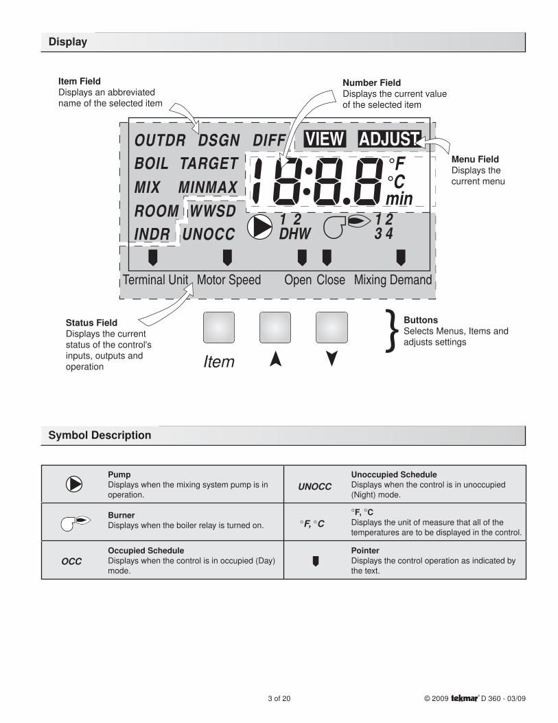
User Interface pg. 2
Description of Display Elements pg. 3
Sequence of Operation pg. 4
Section A: General Operation pg. 4
Section B: Mixing pg. 5
Section C: Boiler Operation pg. 8
Installation pg. 10
DIP Switch Settings pg. 14
The 360 uses a Liquid Crystal Display (LCD) as the method of supplying information. You use the LCD in order to set up and moni-tor the operation of your system. The 360 has three push buttons (Item, , ) for selecting, viewing, and adjusting settings. As you program your control, record your settings in the ADJUST menu table which is found in the second half of this brochure.
ItemThe abbreviated name of the selected item will be displayed in the item field of the dis-play. To view the next available item, press and release the Item button. Once you have reached the last available item, pressing and releasing the Item button will return the display to the first item.
AdjustTo make an adjustment to a setting in the control, press and hold simultaneously for 1 second all 3 buttons. The display will then show the word ADJUST in the top right corner. Then select the desired item using the Item button. Finally use the and/or button to make the adjustment.
To exit the ADJUST menu, either select the ESC item and press the or button, or leave the adjustment buttons alone for 20 sec-onds.
When the Item button is pressed and held in the VIEW menu, the display scrolls through all the adjust items in both access levels.
Additional information can be gained by observing the status field and pointers of the LCD. The status field will indicate which of the control’s outputs are currently active. Most symbols in the status field are only visible when the VIEW menu is selected.
Quick Setup pg. 14
Control Settings pg. 15
View Menu pg. 15
Adjust Menu pg. 16
Testing and Troubleshooting pg. 17
Error Messages pg. 19
Technical Data pg. 20
Limited Warranty pg. 20
Reference Material: Essay E 003 “Characterized Heating Curve and Reset Ratio” Essay E 021 “Mixing Methods and Sizing of Variable Speed Injection Pumps”
Item
Item
3 of 20 © 2009 D 360 - 03/09
Symbol Description
Display
© 2009 D 360 - 03/09 4 of 20
Sequence of Operation
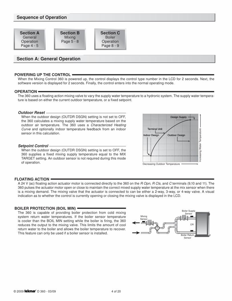
POWERING UP THE CONTROLWhen the Mixing Control 360 is powered up, the control displays the control type number in the LCD for 2 seconds. Next, the software version is displayed for 2 seconds. Finally, the control enters into the normal operating mode.
OPERATIONThe 360 uses a floating action mixing valve to vary the supply water temperature to a hydronic system. The supply water tempera-ture is based on either the current outdoor temperature, or a fixed setpoint.
Outdoor ResetWhen the outdoor design (OUTDR DSGN) setting is not set to OFF, the 360 calculates a mixing supply water temperature based on the outdoor air temperature. The 360 uses a Characterized Heating Curve and optionally indoor temperature feedback from an indoor sensor in this calculation.
Setpoint ControlWhen the outdoor design (OUTDR DSGN) setting is set to OFF, the 360 supplies a fixed mixing supply temperature equal to the MIX TARGET setting. An outdoor sensor is not required during this mode of operation.
FLOATING ACTIONA 24 V (ac) floating action actuator motor is connected directly to the 360 on the R Opn, R Cls, and C terminals (9,10 and 11). The 360 pulses the actuator motor open or close to maintain the correct mixed supply water temperature at the mix sensor when there is a mixing demand. The mixing valve that the actuator is connected to can be either a 2-way, 3-way, or 4-way valve. A visual indication as to whether the control is currently opening or closing the mixing valve is displayed in the LCD.
BOILER PROTECTION (BOIL MIN)The 360 is capable of providing boiler protection from cold mixing system return water temperatures. If the boiler sensor temperature is cooler than the BOIL MIN setting while the boiler is firing, the 360 reduces the output to the mixing valve. This limits the amount of cool return water to the boiler and allows the boiler temperature to recover. This feature can only be used if a boiler sensor is installed.
Section A: General Operation
MixingSensor
Boiler SupplySensor
OR
Boiler ReturnSensor
Decreasing Outdoor Temperature
Incr
easi
ng W
ater
Tem
pera
tureTerminal UnitTerminal Unit
Indoor DesignIndoor Design Outdoor DesignOutdoor Design
Design SupplyDesign Supply
Section AGeneral
OperationPage 4 - 5
Section BMixing
Page 5 - 8
Section CBoiler
OperationPage 8 - 9
5 of 20 © 2009 D 360 - 03/09
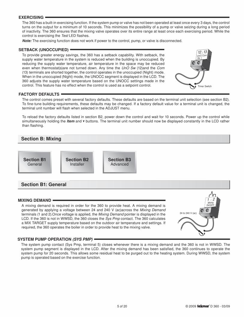
EXERCISINGThe 360 has a built-in exercising function. If the system pump or valve has not been operated at least once every 3 days, the control turns on the output for a minimum of 10 seconds. This minimizes the possibility of a pump or valve seizing during a long period of inactivity. The 360 ensures that the mixing valve operates over its entire range at least once each exercising period. While the control is exercising the Test LED flashes.Note: The exercising function does not work if power to the control, pump, or valve is disconnected.
SETBACK (UNOCCUPIED)To provide greater energy savings, the 360 has a setback capability. With setback, the supply water temperature in the system is reduced when the building is unoccupied. By reducing the supply water temperature, air temperature in the space may be reduced even when thermostat(s)are not turned down. Any time the UnO Sw (12)and the Com (13) terminals are shorted together, the control operates in the unoccupied (Night) mode. When in the unoccupied (Night) mode, the UNOCC segment is displayed in the LCD. The 360 adjusts the supply water temperature based on the UNOCC settings made in the control. This feature has no effect when the control is used as a setpoint control.
FACTORY DEFAULTSThe control comes preset with several factory defaults. These defaults are based on the terminal unit selection (see section B2). To fine-tune building requirements, these defaults may be changed. If a factory default value for a terminal unit is changed, the terminal unit number will flash when selected in the ADJUST menu.
To reload the factory defaults listed in section B2, power down the control and wait for 10 seconds. Power up the control while simultaneously holding the Item and buttons. The terminal unit number should now be displayed constantly in the LCD rather than flashing.
MIXING DEMANDA mixing demand is required in order for the 360 to provide heat. A mixing demand is generated by applying a voltage between 24 and 240 V (ac)across the Mixing Demand terminals (1 and 2).Once voltage is applied, the Mixing Demand pointer is displayed in the LCD. If the 360 is not in WWSD, the 360 closes the Sys Pmp contact. The 360 calculates a MIX TARGET supply temperature based on the outdoor air temperature and settings. If required, the 360 operates the boiler in order to provide heat to the mixing valve.
SYSTEM PUMP OPERATION (SYS PMP)The system pump contact (Sys Pmp, terminal 5) closes whenever there is a mixing demand and the 360 is not in WWSD. The system pump segment is displayed in the LCD. After the mixing demand has been satisfied, the 360 continues to operate the system pump for 20 seconds. This allows some residual heat to be purged out to the heating system. During WWSD, the system pump is operated based on the exercise function.
Section B: Mixing
Section B1: General
12UnOSw
13Com
Timer Switch
1 2Mixing
Demand
24 to 240 V (ac)
Section B1General
Section B2Installer
Section B3Advanced
© 2009 D 360 - 03/09 6 of 20
INDOOR SENSORAn indoor sensor may be used in order to provide indoor temperature feedback. The indoor sensor is connected to the Com and Indr terminals (16 and 18). In addition, power must be applied to the Mixing Demand terminals (1 and 2) as described in the MIXING DEMAND section. With the indoor sensor connected, the 360 is able to sense the actual room temperature. Indoor temperature feedback fine-tunes the supply water temperature in the mixing system to maintain room temperature. To adjust the room tempera-ture, use the ROOM OCC or ROOM UNOCC setting in the ADJUST menu at the control.
If a multiple zone system is used with an indoor sensor, proper placement of the indoor sensor is essential. The indoor sensor should be located in an area which best represents the average air temperature of the zones.
CHARACTERIZED HEATING CURVEWhen used as a mixing reset control, the 360 varies the supply water temperature based on the outdoor air temperature. The control takes into account the type of terminal unit that the system is using. Since different types of terminal units transfer heat to a space using different proportions of radiation, convection and conduction, the supply water temperature must be controlled differ-ently. Once the control is told what type of terminal unit is used, the control varies the supply water temperature according to the type of terminal unit. This improves the control of the air temperature in the building.
MIXING TARGET TEMPERATURE (MIX TARGET)When used as a mixing reset control, the MIX TARGET temperature is calculated from the Characterized Heating Curve settings, outdoor air temperature and optionally, indoor air temperature. When used as a setpoint control, the installer sets the MIX TARGET temperature. The control displays the temperature that it is currently trying to maintain as the mixing supply temperature. If the control does not have a mixing demand,”- - -” is displayed as the MIX TARGET.
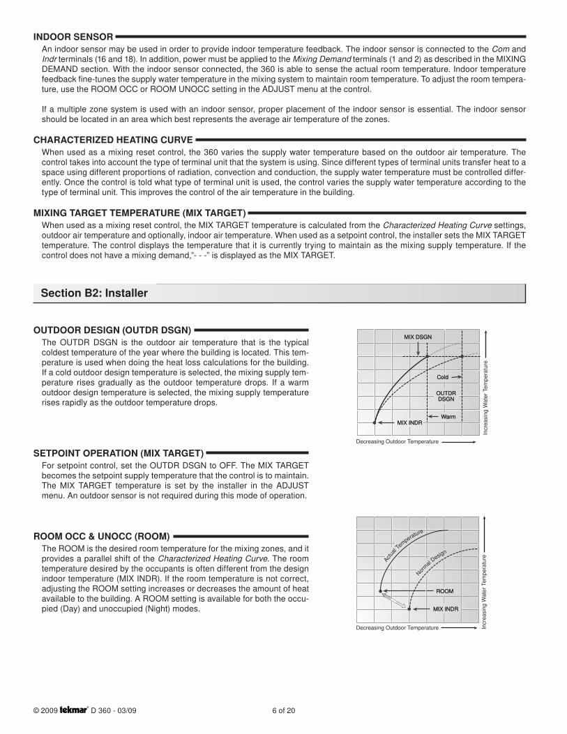
OUTDOOR DESIGN (OUTDR DSGN)The OUTDR DSGN is the outdoor air temperature that is the typical coldest temperature of the year where the building is located. This tem-perature is used when doing the heat loss calculations for the building. If a cold outdoor design temperature is selected, the mixing supply tem-perature rises gradually as the outdoor temperature drops. If a warm outdoor design temperature is selected, the mixing supply temperature rises rapidly as the outdoor temperature drops.
SETPOINT OPERATION (MIX TARGET)For setpoint control, set the OUTDR DSGN to OFF. The MIX TARGET becomes the setpoint supply temperature that the control is to maintain. The MIX TARGET temperature is set by the installer in the ADJUST menu. An outdoor sensor is not required during this mode of operation.
ROOM OCC & UNOCC (ROOM)The ROOM is the desired room temperature for the mixing zones, and it provides a parallel shift of the Characterized Heating Curve. The room temperature desired by the occupants is often different from the design indoor temperature (MIX INDR). If the room temperature is not correct, adjusting the ROOM setting increases or decreases the amount of heat available to the building. A ROOM setting is available for both the occu-pied (Day) and unoccupied (Night) modes.
Decreasing Outdoor Temperature
Incr
easi
ng W
ater
Tem
pera
ture
MIX DSGNMIX DSGN
MIX INDRMIX INDR
OUTDRDSGN
OUTDRDSGN
ColdCold
WarmWarm
Decreasing Outdoor Temperature Incr
easi
ng W
ater
Tem
pera
ture
ROOMROOM
MIX INDRMIX INDR
Actu
al Te
mperature
Nor
mal Design
Section B2: Installer
7 of 20 © 2009 D 360 - 03/09
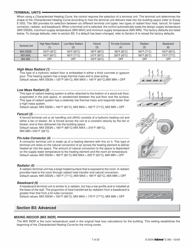
TERMINAL UNITSWhen using a Characterized Heating Curve, the control requires the selection of a terminal unit. The terminal unit determines the shape of the Characterized Heating Curve according to how the terminal unit delivers heat into the building space (refer to Essay E 003). The 360 provides for selection between six different terminal unit types: two types of radiant floor heat, fancoil, fin-tuben convector, radiator, and baseboard. When a terminal unit is selected, the control automatically loads the design supply temperature (MIX DSGN), maximum supply temperature (MIX MAX) and minimum supply temperature (MIX MIN). The factory defaults are listed below. To change defaults, refer to section B3. If a default has been changed, refer to Section A to reload the factory defaults.
High Mass Radiant (1)This type of a hydronic radiant floor is embedded in either a thick concrete or gypsum pour. This heating system has a large thermal mass and is slow acting.Default values: MIX DSGN = 120°F (49°C), MIX MAX = 140°F (60°C),MIX MIN = OFF
Low Mass Radiant (2)This type of radiant heating system is either attached to the bottom of a wood sub-floor, suspended in the joist space, or sandwiched between the sub-floor and the surface. This type of radiant system has a relatively low thermal mass and responds faster than a high mass system.Default values: MIX DSGN = 140°F (60°C), MIX MAX = 160°F (71°C), MIX MIN = OFF
Fancoil (3)A fancoil terminal unit or air handling unit (AHU) consists of a hydronic heating coil and either a fan or blower. Air is forced across the coil at a constant velocity by the fan or blower, and is then delivered into the building space.Default values: MIX DSGN = 190°F (88°C) MIX MAX = 210°F (99°C), MIX MIN =100°F (38°C)
Fin-tube Convector (4)A convector terminal unit is made up of a heating element with fins on it. This type of terminal unit relies on the natural convection of air across the heating element to deliver heated air into the space. The amount of natural convection to the space is dependant on the supply water temperature to the heating element and the room air temperature.Default values: MIX DSGN = 180°F (82°C) MIX MAX = 200°F (93°C), MIX MIN = OFF
Radiator (5)A radiator terminal unit has a large heated surface that is exposed to the room. A radiator provides heat to the room through radiant heat transfer and natural convection.Default values: MIX DSGN = 160°F (71°C), MIX MAX = 180°F (82°C), MIX MIN = OFF
Baseboard (6)A baseboard terminal unit is similar to a radiator, but has a low profile and is installed at the base of the wall. The proportion of heat transferred by radiation from a baseboard is greater than that from a fin-tube convector.Default values: MIX DSGN = 150°F (66°C), MIX MAX = 170°F (77°C), MIX MIN = OFF
MIXING INDOOR (MIX INDR)The MIX INDR is the room temperature used in the original heat loss calculations for the building. This setting establishes the beginning of the Characterized Heating Curve for the mixing zones.
Section B3: Advanced
Terminal UnitHigh Mass Radiant
(1)
MIX DSGNMIX MAXMIX MIN
120°F (49°C)140°F (60°C)
OFF
140°F (60°C)160°F (71°C)
OFF
190°F (88°C)210°F (99°C)100°F (38°C)
180°F (82°C)200°F (93°C)
OFF
160°F (71°C)180°F (82°C)
OFF
150°F (66°C)170°F (77°C)
OFF
Low Mass Radiant(2)
Fancoil(3)
Fin-tube Convector(4)
Radiator(5)
Baseboard(6)
© 2009 D 360 - 03/09 8 of 20
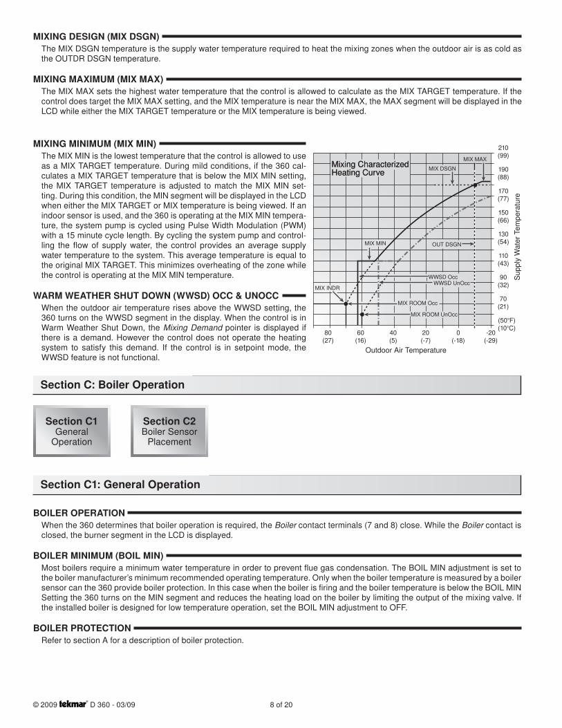
MIXING DESIGN (MIX DSGN)The MIX DSGN temperature is the supply water temperature required to heat the mixing zones when the outdoor air is as cold as the OUTDR DSGN temperature.
MIXING MAXIMUM (MIX MAX)The MIX MAX sets the highest water temperature that the control is allowed to calculate as the MIX TARGET temperature. If the control does target the MIX MAX setting, and the MIX temperature is near the MIX MAX, the MAX segment will be displayed in the LCD while either the MIX TARGET temperature or the MIX temperature is being viewed.
MIXING MINIMUM (MIX MIN)The MIX MIN is the lowest temperature that the control is allowed to use as a MIX TARGET temperature. During mild conditions, if the 360 cal-culates a MIX TARGET temperature that is below the MIX MIN setting, the MIX TARGET temperature is adjusted to match the MIX MIN set-ting. During this condition, the MIN segment will be displayed in the LCD when either the MIX TARGET or MIX temperature is being viewed. If an indoor sensor is used, and the 360 is operating at the MIX MIN tempera-ture, the system pump is cycled using Pulse Width Modulation (PWM) with a 15 minute cycle length. By cycling the system pump and control-ling the flow of supply water, the control provides an average supply water temperature to the system. This average temperature is equal to the original MIX TARGET. This minimizes overheating of the zone while the control is operating at the MIX MIN temperature.
WARM WEATHER SHUT DOWN (WWSD) OCC & UNOCCWhen the outdoor air temperature rises above the WWSD setting, the 360 turns on the WWSD segment in the display. When the control is in Warm Weather Shut Down, the Mixing Demand pointer is displayed if there is a demand. However the control does not operate the heating system to satisfy this demand. If the control is in setpoint mode, the WWSD feature is not functional.
BOILER OPERATIONWhen the 360 determines that boiler operation is required, the Boiler contact terminals (7 and 8) close. While the Boiler contact is closed, the burner segment in the LCD is displayed.
BOILER MINIMUM (BOIL MIN)Most boilers require a minimum water temperature in order to prevent flue gas condensation. The BOIL MIN adjustment is set to the boiler manufacturer’s minimum recommended operating temperature. Only when the boiler temperature is measured by a boiler sensor can the 360 provide boiler protection. In this case when the boiler is firing and the boiler temperature is below the BOIL MIN Setting the 360 turns on the MIN segment and reduces the heating load on the boiler by limiting the output of the mixing valve. If the installed boiler is designed for low temperature operation, set the BOIL MIN adjustment to OFF.
BOILER PROTECTIONRefer to section A for a description of boiler protection.
Section C: Boiler Operation
MIX MAX
MIX DSGN
OUT DSGN
WWSD Occ
MIX ROOM Occ
MIX ROOM UnOcc
WWSD UnOcc
210(99)
190(88)
170(77)
150(66)
130(54)
110(43)
90(32)
70(21)
(50°F)(10°C)
-20(-29)
0(-18)
20(-7)
40(5)
60(16)
80(27)
Outdoor Air Temperature
Sup
ply
Wat
er T
empe
ratu
re
Mixing CharacterizedHeating CurveMixing CharacterizedHeating Curve
MIX MIN
MIX INDR
Section C1: General Operation
Section C1General
Operation
Section C2Boiler Sensor
Placement
9 of 20 © 2009 D 360 - 03/09
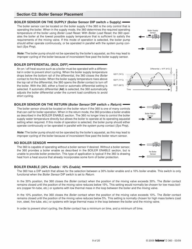
BOILER SENSOR ON THE SUPPLY (Boiler Sensor DIP switch = Supply)The boiler sensor can be located on the boiler supply if the 360 is the only control that is operating the boiler. When in the supply mode, the 360 determines the required operating temperature of the boiler using Boiler Load Reset. With Boiler Load Reset, the 360 oper-ates the boiler at the lowest possible supply temperature that is sufficient to satisfy the requirements of the mixing valve. If this mode of operation is selected, the boiler pump should either operate continuously, or be operated in parallel with the system pump con-tact (Sys Pmp).
Note: The boiler pump should not be operated by the boiler’s aquastat, as this may lead to improper cycling of the boiler because of inconsistent flow past the boiler supply sensor.
BOILER DIFFERENTIAL (BOIL DIFF)An on / off heat source such as a boiler must be operated with a differen-tial in order to prevent short cycling. When the boiler supply temperature drops below the bottom rail of the differential, the 360 closes the Boiler contact to fire the boiler. When the boiler supply temperature rises above the top rail of the differential, the 360 opens the Boiler contact to turn off the boiler. With the 360, either a fixed or automatic differential setting is selected. If automatic differential (Ad) is selected, the 360 automatically adjusts the boiler differential under the current load conditions to avoid short cycling.
BOILER SENSOR ON THE RETURN (Boiler Sensor DIP switch = Return)The boiler sensor should be located on the boiler return if the 360 is one of many controls that can call for boiler operation. When in the return mode, the 360 provides a boiler enable as described in the BOILER ENABLE section. The 360 no longer tries to control the boiler supply water temperature directly but allows the boiler to operate at its operating aquastat setting when required. If this mode of operation is selected, the boiler pump should either operate continuously or be operated in parallel with the system pump contact (Sys Pmp).
Note: The boiler pump should not be operated by the boiler’s aquastat, as this may lead to improper cycling of the boiler because of inconsistent flow past the boiler return sensor.
NO BOILER SENSORThe 360 is capable of operating without a boiler sensor if desired. Without a boiler sensor, the 360 provides a boiler enable as described in the BOILER ENABLE section, but is unable to provide boiler protection. This type of application is typical if the 360 is drawing heat from a heat source that already incorporates some form of boiler protection.
BOILER ENABLE (30% Enable / 10% Enable)The 360 has a DIP switch that allows for the selection between a 30% boiler enable and a 10% boiler enable. This switch is only functional when the Boiler Sensor DIP switch is set to Return.
In the 30% position, the 360 closes the Boiler contact when the position of the mixing valve exceeds 30%. The Boiler contact remains closed until the position of the mixing valve reduces below 15%. This setting would normally be chosen for low mass boil-ers (copper fin-tube, etc.) or systems with low thermal mass in the loop between the boiler and the mixing valve.
In the 10% position, the 360 closes the Boiler contact when the position of the mixing valve exceeds 10%. The Boiler contact remains closed until the position of the mixing valve reduces below 5%. This setting is normally chosen for high mass boilers (cast iron, steel, fire-tube, etc.) or systems with large thermal mass in the loop between the boiler and the mixing valve.
In order to prevent short cycling, the Boiler contact has a minimum on time, and a minimum off time.
Boiler SupplySensor
Boiler ReturnSensor
No Boiler Sensor
Boile
r On
Boile
r On
Time
Sup
ply
Wat
er T
empe
ratu
re
Differential = 10°F (6°C)
165°F (74°C)
160°F (71°C)
155°F (68°C)
Section C2: Boiler Sensor Placement
© 2009 D 360 - 03/09 10 of 20
CAUTION
Improper installation and operation of this control could result in damage to the equipment and possibly even personal injury. It is your responsibility to ensure that this control is safely installed according to all applicable codes and standards. This electronic control is not intended for use as a primary limit control. Other controls that are intended and certified as safety limits must be placed into the control circuit.
STEP ONE — GETTING READYCheck the contents of this package. If any of the contents listed are missing or damaged, please contact your wholesaler or tekmar sales representative for assistance.
Type 360 includes: One Mixing Control 360, One Outdoor Sensor 070, Two Universal Sensors 082, Data Brochures D 360, D 070, D 001,Application Brochure A 360, Essay E 021.
Note: Carefully read the details of the Sequence of Operation to ensure that you have chosen the proper control for your application.
STEP TWO — MOUNTING THE BASERemove the control from its base by pressing down on the release clip in the wiring chamber and sliding the control away from it. The base is then mounted in accordance with the instructions in the Data Brochure D 001.
STEP THREE — ROUGH-IN WIRINGAll electrical wiring terminates in the control base wiring chamber. The base has standard 7/8” (22 mm) knockouts which accept common wiring hardware and conduit fittings. Before removing the knockouts, check the wiring diagram and select those sections of the chamber with common voltages. Do not allow the wiring to cross between sections, as the wires will interfere with safety dividers which should be installed at a later time.
Power must not be applied to any of the wires during the rough-in wiring stage.
• Install the Outdoor Sensor 070, Boiler Sensor 082, and Mixing Sensor 082 according to the instructions in the Data Brochure D 070, and run the wiring back to the control.
• If an Indoor Sensor 076 or 077 is used, install the indoor sensor according to the instructions in the Data Brochure D 074,and run the wiring back to the control.
• Run wire from other system components (pump, boiler, actuating motor, etc.) to the control.
• Run wires from the 120 V (ac) power to the control. Use a clean power source to ensure proper operation. Multi-strand 16 AWG wire is recommended for all 120 V (ac) wiring due to its superior flexibility and ease of installation into the terminals.
STEP FOUR — ELECTRICAL CONNECTIONS TO THE CONTROLThe installer should test to confirm that no voltage is present at any of the wires. Push the control into the base and slide it down until it snaps firmly into place.
Powered Input Connections
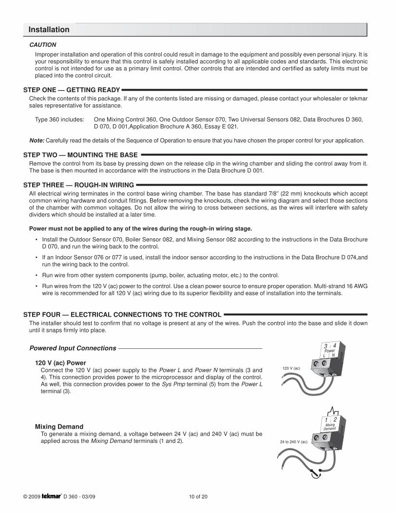
120 V (ac) PowerConnect the 120 V (ac) power supply to the Power L and Power N terminals (3 and 4). This connection provides power to the microprocessor and display of the control. As well, this connection provides power to the Sys Pmp terminal (5) from the Power L terminal (3).
Mixing DemandTo generate a mixing demand, a voltage between 24 V (ac) and 240 V (ac) must be applied across the Mixing Demand terminals (1 and 2).
Installation
3Power
4
120 V (ac)
L N
1 2Mixing
Demand
24 to 240 V (ac)
11 of 20 © 2009 D 360 - 03/09
Output Connections
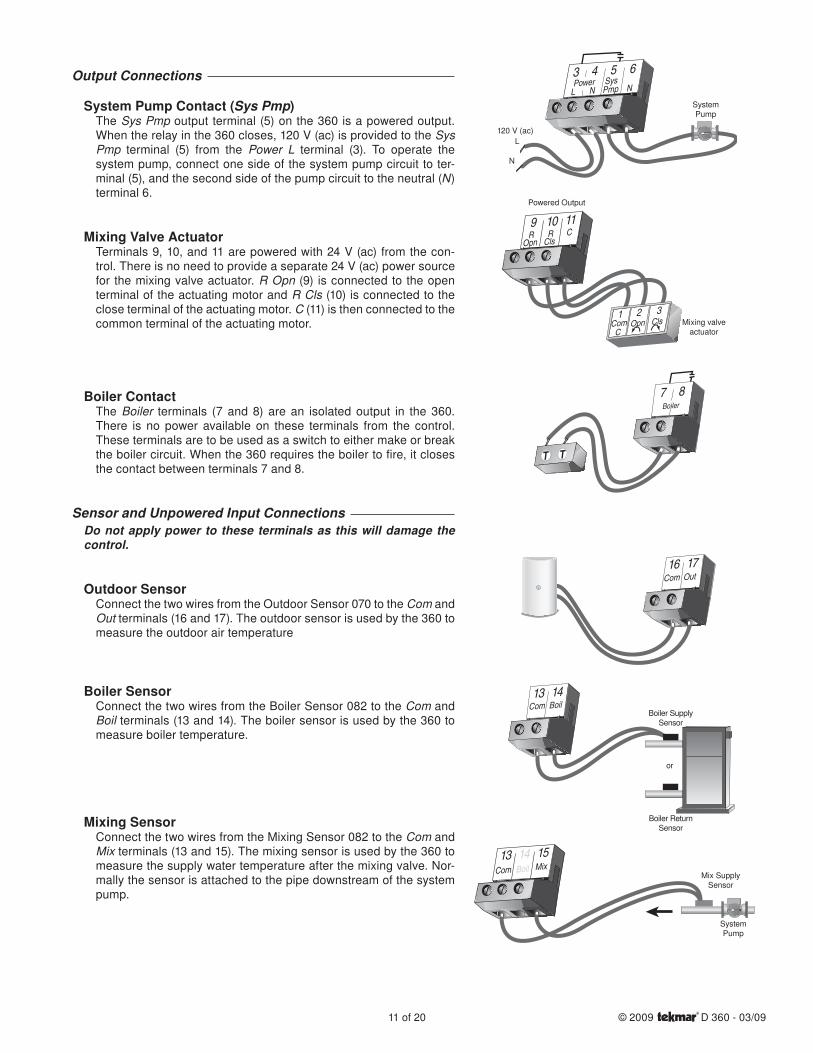
System Pump Contact (Sys Pmp)The Sys Pmp output terminal (5) on the 360 is a powered output. When the relay in the 360 closes, 120 V (ac) is provided to the Sys Pmp terminal (5) from the Power L terminal (3). To operate the system pump, connect one side of the system pump circuit to ter-minal (5), and the second side of the pump circuit to the neutral (N) terminal 6.
Mixing Valve ActuatorTerminals 9, 10, and 11 are powered with 24 V (ac) from the con-trol. There is no need to provide a separate 24 V (ac) power source for the mixing valve actuator. R Opn (9) is connected to the open terminal of the actuating motor and R Cls (10) is connected to the close terminal of the actuating motor. C (11) is then connected to the common terminal of the actuating motor.
Boiler ContactThe Boiler terminals (7 and 8) are an isolated output in the 360. There is no power available on these terminals from the control. These terminals are to be used as a switch to either make or break the boiler circuit. When the 360 requires the boiler to fire, it closes the contact between terminals 7 and 8.
Sensor and Unpowered Input ConnectionsDo not apply power to these terminals as this will damage the control.
Outdoor SensorConnect the two wires from the Outdoor Sensor 070 to the Com and Out terminals (16 and 17). The outdoor sensor is used by the 360 to measure the outdoor air temperature
Boiler SensorConnect the two wires from the Boiler Sensor 082 to the Com and Boil terminals (13 and 14). The boiler sensor is used by the 360 to measure boiler temperature.
Mixing SensorConnect the two wires from the Mixing Sensor 082 to the Com and Mix terminals (13 and 15). The mixing sensor is used by the 360 to measure the supply water temperature after the mixing valve. Nor-mally the sensor is attached to the pipe downstream of the system pump.
43 5 6Power Sys
NL Pmp N
120 V (ac)
SystemPump
N
L
9R
Opn
10R
Cls
11C
Powered Output
Mixing valveactuator
1ComC
Opn Cls2 3
Boiler87
Boiler SupplySensor
or
Boiler ReturnSensor
13 14Com Boil
13Com
14Boil
15Mix
Mix Supply Sensor
SystemPump
16 17Com Out
© 2009 D 360 - 03/09 12 of 20
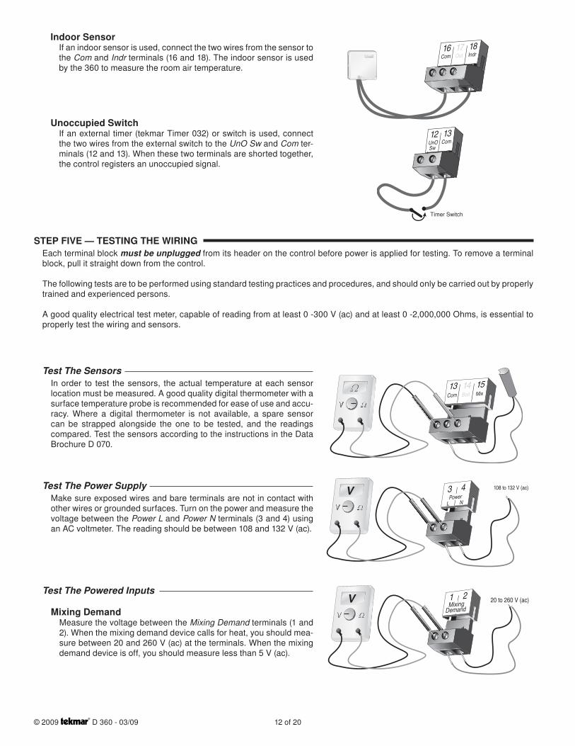
Indoor SensorIf an indoor sensor is used, connect the two wires from the sensor to the Com and Indr terminals (16 and 18). The indoor sensor is used by the 360 to measure the room air temperature.
Unoccupied SwitchIf an external timer (tekmar Timer 032) or switch is used, connect the two wires from the external switch to the UnO Sw and Com ter-minals (12 and 13). When these two terminals are shorted together, the control registers an unoccupied signal.
STEP FIVE — TESTING THE WIRINGEach terminal block must be unplugged from its header on the control before power is applied for testing. To remove a terminal block, pull it straight down from the control.
The following tests are to be performed using standard testing practices and procedures, and should only be carried out by properly trained and experienced persons.
A good quality electrical test meter, capable of reading from at least 0 -300 V (ac) and at least 0 -2,000,000 Ohms, is essential to properly test the wiring and sensors.
Test The SensorsIn order to test the sensors, the actual temperature at each sensor location must be measured. A good quality digital thermometer with a surface temperature probe is recommended for ease of use and accu-racy. Where a digital thermometer is not available, a spare sensor can be strapped alongside the one to be tested, and the readings compared. Test the sensors according to the instructions in the Data Brochure D 070.
Test The Power SupplyMake sure exposed wires and bare terminals are not in contact with other wires or grounded surfaces. Turn on the power and measure the voltage between the Power L and Power N terminals (3 and 4) using an AC voltmeter. The reading should be between 108 and 132 V (ac).
Test The Powered Inputs
Mixing DemandMeasure the voltage between the Mixing Demand terminals (1 and 2). When the mixing demand device calls for heat, you should mea-sure between 20 and 260 V (ac) at the terminals. When the mixing demand device is off, you should measure less than 5 V (ac).
16Com
17Out
18Indr
12UnOSw
13Com
Timer Switch
13Com
14Boil
15Mix
L N
43Power
V 108 to 132 V (ac)
1 2Mixing
DemandV 20 to 260 V (ac)
13 of 20 © 2009 D 360 - 03/09
Test The Outputs
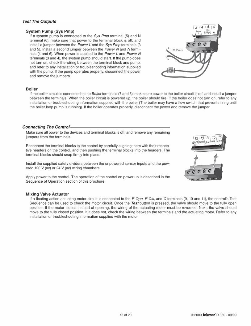
System Pump (Sys Pmp)If a system pump is connected to the Sys Pmp terminal (5) and N terminal (6), make sure that power to the terminal block is off, and install a jumper between the Power L and the Sys Pmp terminals (3 and 5). Install a second jumper between the Power N and N termi-nals (4 and 6). When power is applied to the Power L and Power N terminals (3 and 4), the system pump should start. If the pump does not turn on, check the wiring between the terminal block and pump, and refer to any installation or troubleshooting information supplied with the pump. If the pump operates properly, disconnect the power and remove the jumpers.
BoilerIf the boiler circuit is connected to the Boiler terminals (7 and 8), make sure power to the boiler circuit is off, and install a jumper between the terminals. When the boiler circuit is powered up, the boiler should fire. If the boiler does not turn on, refer to any installation or troubleshooting information supplied with the boiler (The boiler may have a flow switch that prevents firing until the boiler loop pump is running). If the boiler operates properly, disconnect the power and remove the jumper.
Connecting The ControlMake sure all power to the devices and terminal blocks is off, and remove any remaining jumpers from the terminals.
Reconnect the terminal blocks to the control by carefully aligning them with their respec-tive headers on the control, and then pushing the terminal blocks into the headers. The terminal blocks should snap firmly into place.
Install the supplied safety dividers between the unpowered sensor inputs and the pow-ered 120 V (ac) or 24 V (ac) wiring chambers.
Apply power to the control. The operation of the control on power up is described in the Sequence of Operation section of this brochure.
Mixing Valve ActuatorIf a floating action actuating motor circuit is connected to the R Opn, R Cls, and C terminals (9, 10 and 11), the control’s Test Sequence can be used to check the motor circuit. Once the Test button is pressed, the valve should move to the fully open position. If the motor closes instead of opening, the wiring of the actuating motor must be reversed. Next, the valve should move to the fully closed position. If it does not, check the wiring between the terminals and the actuating motor. Refer to any installation or troubleshooting information supplied with the motor.
12BoilUnO
SwCom
Mix
Com
13 14 15 16
3LPower
4N
5Sys
Pmp
6 N
N
L120 V (ac)
© 2009 D 360 - 03/09 14 of 20
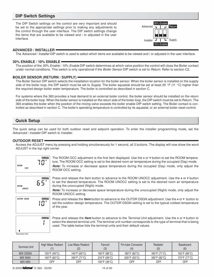
The DIP Switch settings on the control are very important and should be set to the appropriate settings prior to making any adjustments to the control through the user interface. The DIP switch settings change the items that are available to be viewed and / or adjusted in the user interface.
ADVANCED / INSTALLERThe Advanced / Installer DIP switch is used to select which items are available to be viewed and / or adjusted in the user interface.
30% ENABLE / 10% ENABLEThe position of the 30% Enable / 10% Enable DIP switch determines at which valve position the control will close the Boiler contact under normal conditions. This switch is only operational if the Boiler Sensor DIP switch is set to Return. Refer to section C2.
BOILER SENSOR (RETURN / SUPPLY)The Boiler Sensor DIP switch selects the installation location for the boiler sensor. When the boiler sensor is installed on the supply side of the boiler loop, the DIP switch must be set to Supply. The boiler aquastat should be set at least 20 °F (11 °C) higher than the required design boiler water temperature. The boiler is controlled as described in section C.
For systems where the 360 provides a heat demand to an external boiler control, the boiler sensor should be installed on the return side of the boiler loop. When the boiler sensor is installed on the return side of the boiler loop, the DIP switch must be set to Return. The 360 enables the boiler when the position of the mixing valve exceeds the boiler enable DIP switch setting. The Boiler contact is con-trolled as described in section C. The boiler’s operating temperature is controlled by its aquastat, or an external boiler reset control.
The quick setup can be used for both outdoor reset and setpoint operation. To enter the installer programming mode, set the Advanced / Installer DIP switch to Installer.
OUTDOOR RESETAccess the ADJUST menu by pressing and holding simultaneously for 1 second, all 3 buttons. The display will now show the word ADJUST in the top right corner.
The ROOM OCC adjustment is the first item displayed. Use the or button to set the ROOM tempera-ture. The ROOM OCC setting is set to the desired room air temperature during the occupied (Day) mode.Note: To increase or decrease space temperature during the occupied (Day) mode, only adjust the ROOM OCC setting.
Press and release the Item button to advance to the ROOM UNOCC adjustment. Use the or button to set the desired temperature. The ROOM UNOCC setting is set to the desired room air temperature during the unoccupied (Night) mode.Note: To increase or decrease space temperature during the unoccupied (Night) mode, only adjust the ROOM UNOCC setting.
Press and release the Item button to advance to the OUTDR DSGN adjustment. Use the or button to set the outdoor design temperature. The OUTDR DSGN setting is set to the typical coldest temperature of the year.
Press and release the Item button to advance to the Terminal Unit adjustment. Use the or button to select the desired terminal unit. The terminal unit number corresponds to the type of terminal that is being used. The table below lists the terminal units and their default values.
30% EnableAdvanced
Installer
Return
Supply10% Enable
DIP Switch Settings
Quick Setup
Terminal UnitHigh Mass Radiant
(1)
MIX DSGNMIX MAXMIX MIN
120°F (49°C)140°F (60°C)
OFF
140°F (60°C)160°F (71°C)
OFF
190°F (88°C)210°F (99°C)100°F (38°C)
180°F (82°C)200°F (93°C)
OFF
160°F (71°C)180°F (82°C)
OFF
150°F (66°C)170°F (77°C)
OFF
Low Mass Radiant(2)
Fancoil(3)
Fin-tube Convector(4)
Radiator(5)
Baseboard(6)
Terminal Unit
15 of 20 © 2009 D 360 - 03/09
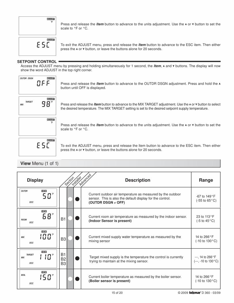
Press and release the Item button to advance to the units adjustment. Use the or button to set the scale to °F or °C.
To exit the ADJUST menu, press and release the Item button to advance to the ESC item. Then either press the or button, or leave the buttons alone for 20 seconds.
SETPOINT CONTROLAccess the ADJUST menu by pressing and holding simultaneously for 1 second, the Item, and buttons. The display will now show the word ADJUST in the top right corner.
Press and release the Item button to advance to the OUTDR DSGN adjustment. Press and hold the button until OFF is displayed.
Press and release the Item button to advance to the MIX TARGET adjustment. Use the or button to select the desired temperature. The MIX TARGET setting is set to the desired setpoint supply temperature.
Press and release the Item button to advance to the units adjustment. Use the or button to set the scale to °F or °C.
To exit the ADJUST menu, press and release the Item button to advance to the ESC item. Then either press the or button, or leave the buttons alone for 20 seconds.
View Menu (1 of 1)
Sectio
n
Instal
ler
Advan
ced
RangeDescriptionDisplay
Current outdoor air temperature as measured by the outdoor sensor. This is also the default display for the control.(OUTDR DSGN ≠ OFF)
Current room air temperature as measured by the indoor sensor.(Indoor Sensor is present)
Current mixed supply water temperature as measured by themixing sensor
Target mixed supply is the temperature the control is currentlytrying to maintain at the mixing sensor.
Current boiler temperature as measured by the boiler sensor.(Boiler sensor is present)
-67 to 149°F(-55 to 65°C)
23 to 113°F(-5 to 45°C)
---, 14 to 266°F(---, -10 to 130°C)
14 to 266°F(-10 to 130°C)
14 to 266°F(-10 to 130°C)
B1
B3
B2B1
B3
© 2009 D 360 - 03/09 16 of 20
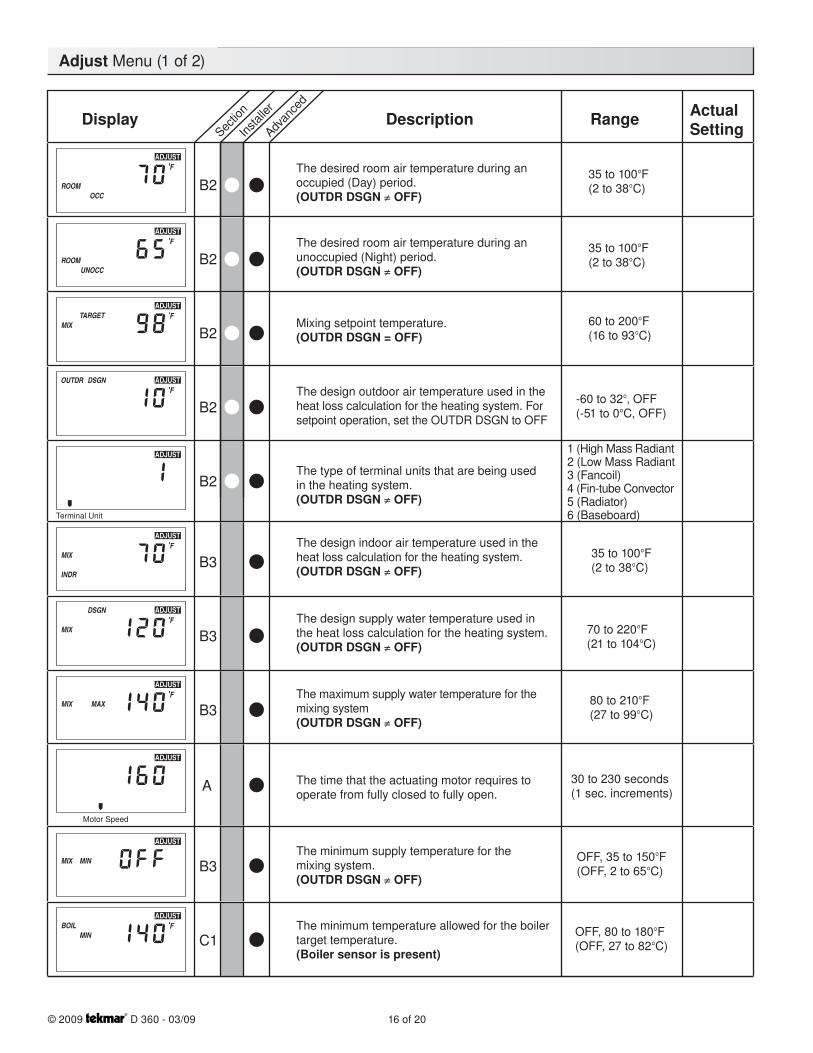
Adjust Menu (1 of 2)
Sectio
n
Instal
ler
Advan
ced
Range ActualSettingDescriptionDisplay
B2The desired room air temperature during anoccupied (Day) period.(OUTDR DSGN ≠ OFF)
35 to 100°F(2 to 38°C)
The desired room air temperature during anunoccupied (Night) period.(OUTDR DSGN ≠ OFF)
35 to 100°F(2 to 38°C)B2
Mixing setpoint temperature.(OUTDR DSGN = OFF)
60 to 200°F(16 to 93°C)B2
The design outdoor air temperature used in theheat loss calculation for the heating system. Forsetpoint operation, set the OUTDR DSGN to OFF
-60 to 32°, OFF(-51 to 0°C, OFF)B2
The design indoor air temperature used in theheat loss calculation for the heating system. (OUTDR DSGN ≠ OFF)
35 to 100°F(2 to 38°C)B3
The design supply water temperature used inthe heat loss calculation for the heating system.(OUTDR DSGN ≠ OFF)
70 to 220°F(21 to 104°C)B3
The maximum supply water temperature for themixing system(OUTDR DSGN ≠ OFF)
80 to 210°F(27 to 99°C)B3
The minimum supply temperature for themixing system.(OUTDR DSGN ≠ OFF)
OFF, 35 to 150°F(OFF, 2 to 65°C)B3
The minimum temperature allowed for the boilertarget temperature.(Boiler sensor is present)
OFF, 80 to 180°F(OFF, 27 to 82°C)C1
The type of terminal units that are being usedin the heating system.(OUTDR DSGN ≠ OFF)
1 (High Mass Radiant2 (Low Mass Radiant3 (Fancoil)4 (Fin-tube Convector5 (Radiator)6 (Baseboard)
B2
Terminal Unit
The time that the actuating motor requires to operate from fully closed to fully open.
30 to 230 seconds(1 sec. increments)A
Motor Speed
17 of 20 © 2009 D 360 - 03/09
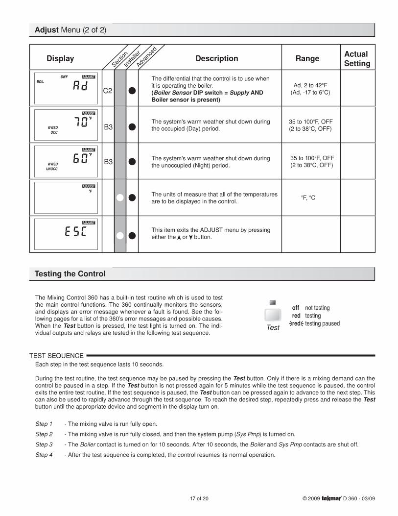
The Mixing Control 360 has a built-in test routine which is used to test the main control functions. The 360 continually monitors the sensors, and displays an error message whenever a fault is found. See the fol-lowing pages for a list of the 360’s error messages and possible causes. When the Test button is pressed, the test light is turned on. The indi-vidual outputs and relays are tested in the following test sequence.
TEST SEQUENCEEach step in the test sequence lasts 10 seconds.
During the test routine, the test sequence may be paused by pressing the Test button. Only if there is a mixing demand can the control be paused in a step. If the Test button is not pressed again for 5 minutes while the test sequence is paused, the control exits the entire test routine. If the test sequence is paused, the Test button can be pressed again to advance to the next step. This can also be used to rapidly advance through the test sequence. To reach the desired step, repeatedly press and release the Test button until the appropriate device and segment in the display turn on.
Step 1 - The mixing valve is run fully open.
Step 2 - The mixing valve is run fully closed, and then the system pump (Sys Pmp) is turned on.
Step 3 - The Boiler contact is turned on for 10 seconds. After 10 seconds, the Boiler and Sys Pmp contacts are shut off.
Step 4 - After the test sequence is completed, the control resumes its normal operation.
Test
Adjust Menu (2 of 2)
Sectio
n
Instal
ler
Advan
ced
Range ActualSettingDescriptionDisplay
C2
The differential that the control is to use whenit is operating the boiler.(Boiler Sensor DIP switch = Supply ANDBoiler sensor is present)
Ad, 2 to 42°F(Ad, -17 to 6°C)
The system's warm weather shut down duringthe occupied (Day) period.
35 to 100°F, OFF(2 to 38°C, OFF)B3
The system's warm weather shut down duringthe unoccupied (Night) period.
35 to 100°F, OFF(2 to 38°C, OFF)B3
The units of measure that all of the temperaturesare to be displayed in the control.
°F, °C
This item exits the ADJUST menu by pressingeither the or button.
Testing the Control
© 2009 D 360 - 03/09 18 of 20
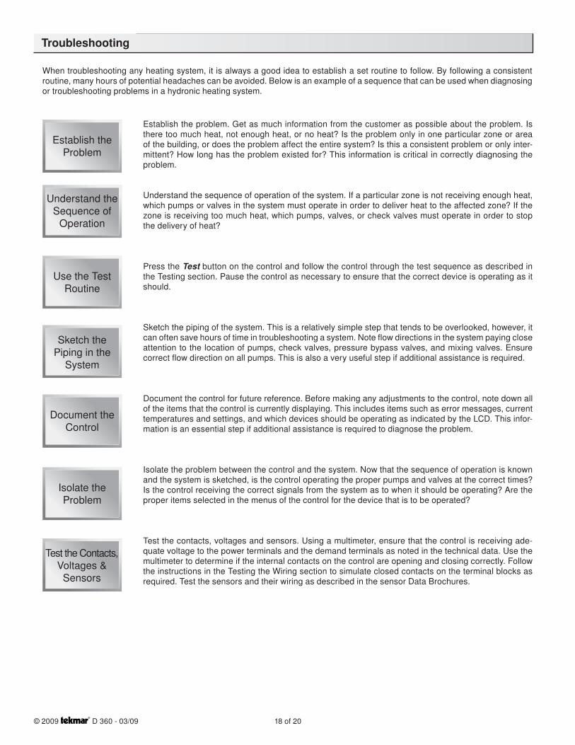
When troubleshooting any heating system, it is always a good idea to establish a set routine to follow. By following a consistent routine, many hours of potential headaches can be avoided. Below is an example of a sequence that can be used when diagnosing or troubleshooting problems in a hydronic heating system.
Establish the problem. Get as much information from the customer as possible about the problem. Is there too much heat, not enough heat, or no heat? Is the problem only in one particular zone or area of the building, or does the problem affect the entire system? Is this a consistent problem or only inter-mittent? How long has the problem existed for? This information is critical in correctly diagnosing the problem.
Understand the sequence of operation of the system. If a particular zone is not receiving enough heat, which pumps or valves in the system must operate in order to deliver heat to the affected zone? If the zone is receiving too much heat, which pumps, valves, or check valves must operate in order to stop the delivery of heat?
Press the Test button on the control and follow the control through the test sequence as described in the Testing section. Pause the control as necessary to ensure that the correct device is operating as it should.
Sketch the piping of the system. This is a relatively simple step that tends to be overlooked, however, it can often save hours of time in troubleshooting a system. Note flow directions in the system paying close attention to the location of pumps, check valves, pressure bypass valves, and mixing valves. Ensure correct flow direction on all pumps. This is also a very useful step if additional assistance is required.
Document the control for future reference. Before making any adjustments to the control, note down all of the items that the control is currently displaying. This includes items such as error messages, current temperatures and settings, and which devices should be operating as indicated by the LCD. This infor-mation is an essential step if additional assistance is required to diagnose the problem.
Isolate the problem between the control and the system. Now that the sequence of operation is known and the system is sketched, is the control operating the proper pumps and valves at the correct times? Is the control receiving the correct signals from the system as to when it should be operating? Are the proper items selected in the menus of the control for the device that is to be operated?
Test the contacts, voltages and sensors. Using a multimeter, ensure that the control is receiving ade-quate voltage to the power terminals and the demand terminals as noted in the technical data. Use the multimeter to determine if the internal contacts on the control are opening and closing correctly. Follow the instructions in the Testing the Wiring section to simulate closed contacts on the terminal blocks as required. Test the sensors and their wiring as described in the sensor Data Brochures.
Establish theProblem
Understand theSequence of
Operation
Use the TestRoutine
Sketch thePiping in the
System
Document theControl
Isolate theProblem
Test the Contacts, Voltages &
Sensors
Troubleshooting
19 of 20 © 2009 D 360 - 03/09
The control was unable to read a piece of information from its EEPROM. This error can be caused by a noisy power source. The control will load the factory defaults and stop operation until all the settings are verified.
The control is no longer able to read the outdoor sensor due to a short circuit. In this case the control assumes an outdoor temperature of 32°F (0°C) and continues operation. Locate and repair the problem as described in the Data Brochure D 070. To clear the error message from the control after the sensor has been repaired, press the Item button.
The control is no longer able to read the outdoor sensor due to an open circuit. In this case the control assumes an outdoor temperature of 32°F (0°C) and continues operation. Locate and repair the problem as described in the Data Brochure D 070. To clear the error message from the control after the sensor has been repaired, press the Item button.
The control is no longer able to read the mixing supply sensor due to a short circuit. In this case the control will operate the mixing valve at a fixed output as long as there is a mixing demand. Locate and repair the problem as described in the Data Brochure D 070. To clear the error message from the control after the sensor has been repaired, press the Item button.
The control is no longer able to read the mixing supply sensor due to a short circuit. In this case the control will operate the mixing valve at a fixed output as long as there is a mixing demand. Locate and repair the problem as described in the Data Brochure D 070. To clear the error message from the control after the sensor has been repaired, press the Item button.
The control is no longer able to read the boiler sensor due to a short circuit. If the BOIL MIN adjustment is higher than 100°F (38°C), the control closes the Boiler contact when the mixing valve starts to oper-ate. The boiler temperature is then limited by the operating aquastat. If the BOIL MIN adjustment is lower than 100°F (38°C), the control does not operate the Boiler contact. Locate and repair the problem as described in the Data Brochure D 070. To clear the error message from the control after the sensor has been repaired, press the Item button.
The control is no longer able to read the boiler sensor due to an open circuit. If the BOIL MIN adjustment is higher than 100°F (38°C), the control closes the Boiler contact when the mixing valve starts to oper-ate. The boiler temperature is then limited by the operating aquastat. If the BOIL MIN adjustment is lower than 100°F (38°C), the control does not operate the Boiler contact. Locate and repair the problem as described in the Data Brochure D 070. If the boiler sensor is deliberately removed, the control must be powered down, and then powered back up. To clear the error message from the control after the sensor has been repaired, press the Item button.
The control is no longer able to read the indoor sensor due to a short circuit. The control will continue to operate as if there was nothing connected to the indoor sensor input. Locate and repair the problem as described in the Data Brochure D 074. To clear the error message from the control after the sensor has been repaired, press the Item button.
The control is no longer able to read the indoor sensor due to an open circuit. The control will continue to operate as if there was nothing connected to the indoor sensor input. Locate and repair the problem as described in the Data Brochure D 074. If the indoor sensor is deliberately removed, the control must be powered down, and then powered back up. To clear the error message from the control after the sensor has been repaired, press the Item button.
The control enclosure has overheated or control has an internal error. The control will stop operation until condition is corrected. Try resetting by powering down, waiitng for 1 minute, and powering back up.
Error Messages
L N N Opn Cls SwSysPmp
R R C UnO Com Boil Mix Com Out Indr
1 2 3 5 9 10 114 6 7 8 12 13 14 15 16 17 18
Mixing Control 360Floating Action
Do not apply power
Signal wiring must be rated at least 300 V.Mixing Power Boiler
Demand
Advanced
Boiler Sensor
Installer Supply
30% Enable
10% Enable
Return
Test
TerminalUnit
MotorSpeed
Open Close MixingDemand
Made in Canada bytekmar Control Systems Ltd.tektra 912-02
Power: 120 V 50/60 Hz 1300 VAFloating Output: 24 V (ac) 0.34 A 8 VARelays: 240 V (ac) 10 A 1/3 hpDemand: 20 to 260 V (ac) 2 VA
H117
0E
Item
Powered Output
To increase or decrease thebuilding temperature.
• Press the Item, , buttonssimultaneously for 1 sec. toenter the ADJUST menu• Use the, , buttons to adjustthe ROOM setting
Display defaults back to VIEWmenu after 20 sec.
ROOM - Set to desired room temp.OUTDR DSGN - Set to coldest (design)outdoor temp.Terminal Unit Set toHigh Mass Radiant 1Low Mass Radiant 2Fan Coil 3Convector 4Radiator 5Baseboard 6
Refer to brochure for more information
Installer Instructions
Meets Class B:Canadian ICESFCC Part 15
Date
Cod
e
20 of 20Product design, software and literature are Copyright © 2009 by:tekmar Control Systems Ltd. and tekmar Control Systems, Inc.
All specifications are subject to change without notice.Printed in Canada. D 360 - 03/09.
Technical Data
Limited Warranty and Product Return Procedure
Limited Warranty The liability of tekmar under this warranty is limited. The Purchaser, by taking receipt of any tekmar product (“Product”), acknowledges the terms of the Limited Warranty in effect at the time of such Product sale and acknowledges that it has read and understands same.
The tekmar Limited Warranty to the Purchaser on the Products sold hereunder is a manufacturer’s pass-through warranty which the Purchaser is authorized to pass through to its customers. Under the Limited Warranty, each tekmar Prod-uct is warranted against defects in workmanship and materials if the Product is installed and used in compliance with tekmar’s instructions, ordinary wear and tear excepted. The pass-through warranty period is for a period of twenty-four (24) months from the production date if the Product is not installed during that period, or twelve (12) months from the documented date of installation if installed within twenty-four (24) months from the production date.
The liability of tekmar under the Limited Warranty shall be limited to, at tekmar’s sole discretion: the cost of parts and labor provided by tekmar to repair defects in materials and/or workmanship of the defective product; or to the exchange of the defective product for a warranty replacement product; or to the granting of credit limited to the original cost of the defective product, and such repair, exchange or credit shall be the sole remedy available from tekmar, and, without limiting the foregoing in any way, tekmar is not responsible, in contract, tort or strict prod-uct liability, for any other losses, costs, expenses, inconveniences, or damages, whether direct, indirect, special, secondary, incidental or consequential, arising from ownership or use of the product, or from defects in workmanship or materials, including any liability for fundamental breach of contract.
The pass-through Limited Warranty applies only to those defective Products returned to tekmar during the warranty period. This Limited Warranty does not cover the cost of the parts or labor to remove or transport the defective Product, or to reinstall the repaired or replacement Product, all such costs and expenses being subject to Purchaser’s agreement and warranty with its customers.
Any representations or warranties about the Products made by Purchaser to its customers which are different from or in excess of the tekmar Limited Warranty are
the Purchaser’s sole responsibility and obligation. Purchaser shall indemnify and hold tekmar harmless from and against any and all claims, liabilities and damages of any kind or nature which arise out of or are related to any such representations or warranties by Purchaser to its customers.
The pass-through Limited Warranty does not apply if the returned Product has been damaged by negligence by persons other than tekmar, accident, fire, Act of God, abuse or misuse; or has been damaged by modifications, alterations or attachments made subsequent to purchase which have not been authorized by tekmar; or if the Product was not installed in compliance with tekmar’s instructions and/or the local codes and ordinances; or if due to defective installation of the Product; or if the Product was not used in compliance with tekmar’s instructions.
THIS WARRANTY IS IN LIEU OF ALL OTHER WARRANTIES, EXPRESS OR IMPLIED, WHICH THE GOVERNING LAW ALLOWS PARTIES TO CON-TRACTUALLY EXCLUDE, INCLUDING, WITHOUT LIMITATION, IMPLIED WARRANTIES OF MERCHANTABILITY AND FITNESS FOR A PARTICULAR PURPOSE, DURABILITY OR DESCRIPTION OF THE PRODUCT, ITS NON-INFRINGEMENT OF ANY RELEVANT PATENTS OR TRADEMARKS, AND ITS COMPLIANCE WITH OR NON-VIOLATION OF ANY APPLICABLE ENVIRON-MENTAL, HEALTH OR SAFETY LEGISLATION; THE TERM OF ANY OTHER WARRANTY NOT HEREBY CONTRACTUALLY EXCLUDED IS LIMITED SUCH THAT IT SHALL NOT EXTEND BEYOND TWENTY-FOUR (24) MONTHS FROM THE PRODUCTION DATE, TO THE EXTENT THAT SUCH LIMITATION IS ALLOWED BY THE GOVERNING LAW.
Product Warranty Return Procedure All Products that are believed to have defects in workmanship or materials must be returned, together with a written description of the defect, to the tekmar Representative assigned to the territory in which such Product is located. If tekmar receives an inquiry from someone other than a tekmar Representative, including an inquiry from Purchaser (if not a tekmar Representative) or Purchaser’s customers, regarding a potential warranty claim, tekmar’s sole obligation shall be to provide the address and other contact informa-tion regarding the appropriate Representative.
The installer must ensure that this control and its wiring are isolated and/or shielded from strong sources of electromagnetic noise. Conversely, this Class B digital appa-ratus complies with Part 15 of the FCC Rules and meets all requirements of the Canadian Interference-Causing Equipment Regulations. However, if this control does cause harmful interference to radio or television reception, which is determined by turning the control off and on, the user is encouraged to try to correct the interference by re-orientating or relocating the receiving antenna, relocating the receiver with respect to this control, and/or connecting the control to a different circuit from that to which the receiver is connected.
Cet appareil numérique de la classe B respecte toutes les exigences du Règlement sur le matériel brouilleur du Canada.
Caution The nonmetallic enclosure does not provide grounding between conduit connections. Use grounding type bushings and jumper wires.
Attention Un boîtier nonmétallique n’assure pas la continuité électrique des conduits. Utiliser des manchons ou des fils de accord spécialement conçus pour
tekmar Control Systems Ltd., Canadatekmar Control Systems, Inc., U.S.A.Head Office: 5100 Silver Star RoadVernon, B.C. Canada V1B 3K4(250) 545-7749 Fax. (250) 545-0650Web Site: www.tekmarcontrols.com
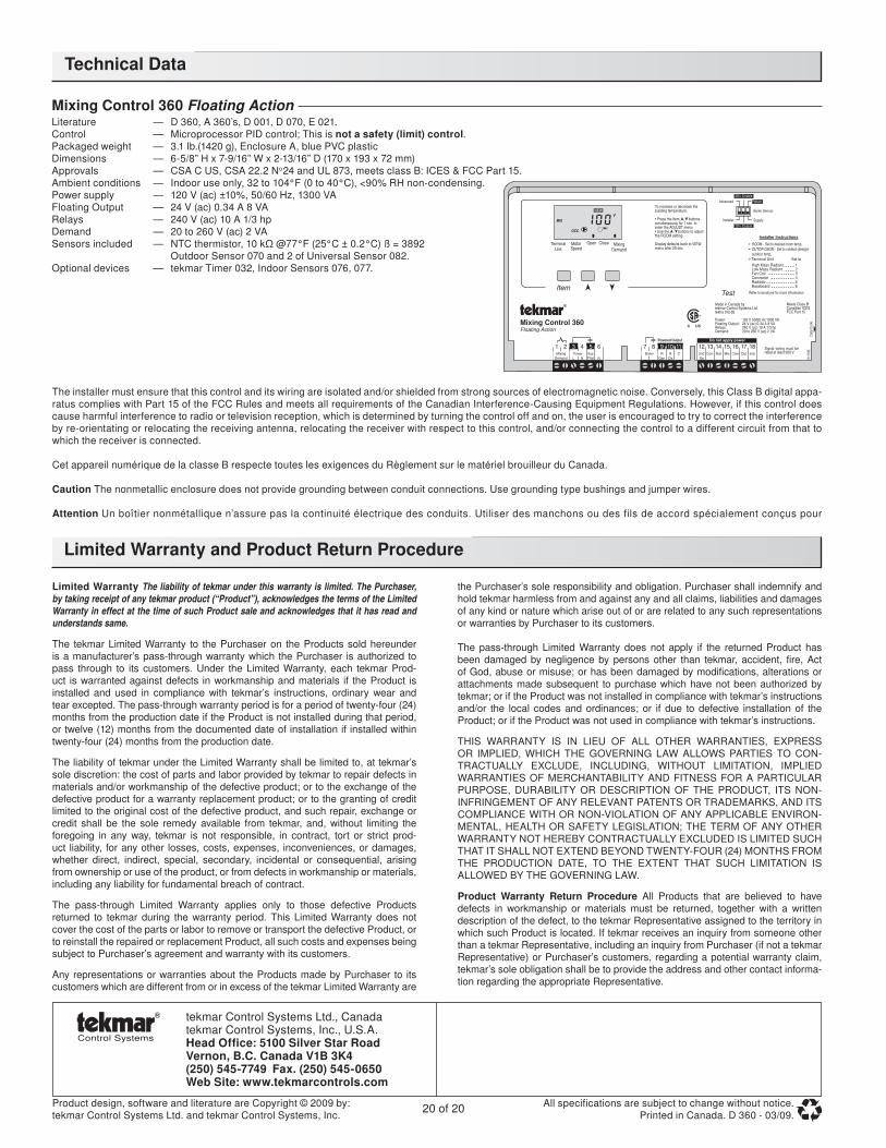
Mixing Control 360 Floating ActionLiterature — D 360, A 360’s, D 001, D 070, E 021.Control — Microprocessor PID control; This is not a safety (limit) control.Packaged weight — 3.1 lb.(1420 g), Enclosure A, blue PVC plasticDimensions — 6-5/8” H x 7-9/16” W x 2-13/16” D (170 x 193 x 72 mm)Approvals — CSA C US, CSA 22.2 No 24 and UL 873, meets class B: ICES & FCC Part 15. Ambient conditions — Indoor use only, 32 to 104°F (0 to 40°C), <90% RH non-condensing.Power supply — 120 V (ac) ±10%, 50/60 Hz, 1300 VAFloating Output — 24 V (ac) 0.34 A 8 VARelays — 240 V (ac) 10 A 1/3 hpDemand — 20 to 260 V (ac) 2 VASensors included — NTC thermistor, 10 kΩ @77°F (25°C ± 0.2°C) ß = 3892 Outdoor Sensor 070 and 2 of Universal Sensor 082.Optional devices — tekmar Timer 032, Indoor Sensors 076, 077.