Embed Size (px)
Citation preview

3-1© Copyright 1997, The University of New Mexico
Network Technologies (I)
• Data Transmission• Transmission Media• Cabling Systems• LAN Technologies
– Ethernet– Token Ring– FDDI
3-2© Copyright 1997, The University of New Mexico
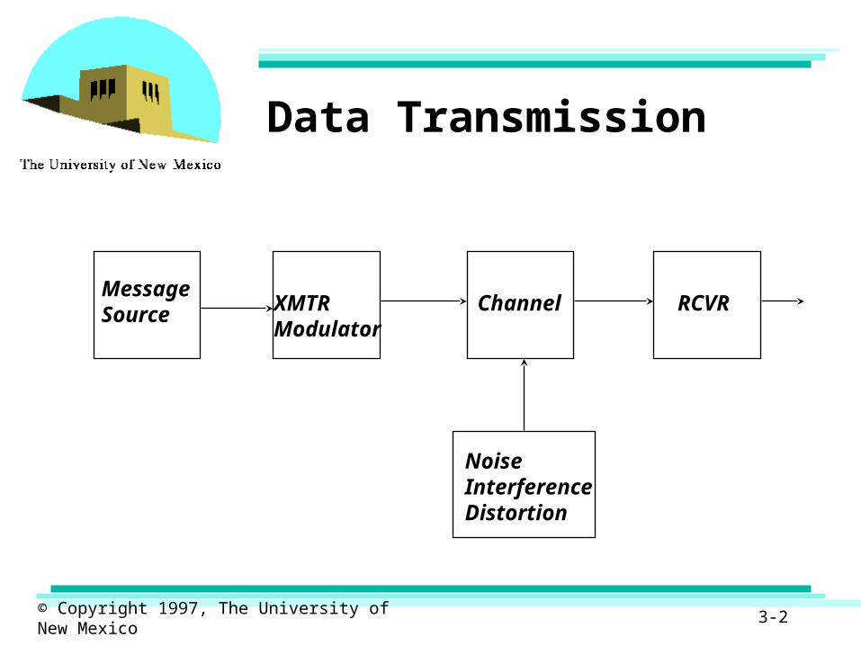
Data Transmission
Message Source XMTR
ModulatorChannel
NoiseInterferenceDistortion
RCVR
3-3© Copyright 1997, The University of New Mexico
Data Transmission
• Transmission of data depends on– Quality of signal– Characteristics of medium
• Need to do signal processing• Need to measure quality of received signal
– Analog: signal-to-noise ratio– Digital: probability of symbol error
• To transmit bits (0’s or 1’s) we need to map them into electromagnetic waves. Modulation techniques.

3-4© Copyright 1997, The University of New Mexico
Data Transmission
• Transmitted signals are– Attenuated– Distorted– Corrupted by noise
• Attenuation and distortion depend on– Type of transmission medium– Bit rate– Distance
• Medium determines– Data rate– Bandwidth of channel
3-5© Copyright 1997, The University of New Mexico
Data Transmission
• Medium:– Guided: twisted pair, coaxial cable, optical fiber– Unguided: radio, satellite, infrared, microwave
• Direct link: point-to-point or guided– Two devices share the medium (intermediate repeaters,
amplifiers)
• Indirect link: multipoint or broadcast– More than two devices share the medium
• Transmission modes: simplex, half-duplex, full-duplex
• Frequency, spectrum, bandwidth– Time-domain vs. frequency domain
3-6© Copyright 1997, The University of New Mexico
Data Transmission
• Bandwidth: several criteria, choice depends on application (3dB or 50% power; fraction of signal power)
• Nyquist formula– Maximum data rate as a function of channel bandwidth
(BW)• if BW=B then max. data rate is 2B• 2 levels per signaling element
– General• C = 2B log2 (M) [bps], M = levels per signaling element
3-7© Copyright 1997, The University of New Mexico
Data Transmission
• Attenuation: strength of signal falls off with distance; increases as a function of frequency
• Delay distortion: propagation velocity varies with frequency; different frequency components arrive at different times
• Noise: thermal, intermodulation, crosstalk, quantization, impulse
• Data rate: C = B log2 (1 + S/N) [bps]
3-8© Copyright 1997, The University of New Mexico
Transmission Medium
• Twisted pair• Coaxial cable• Optical fiber• Wireless
3-9© Copyright 1997, The University of New Mexico
Transmission Medium
• Twisted pair (UTP, STP)– two insulated copper wires arranged in a spiral fashion– wire pair acts as a single communication link– twist length varies from 2-6 inches– thickness varies from 0.016 to 0.036 inches– used in telephone networks– used within buildings– inexpensive compared to other media– easy to work with– poor noise and interference immunity– twisted to avoid crosstalk
3-10© Copyright 1997, The University of New Mexico
Transmission Medium
• Twisted pair (UTP, STP)– analog signal amplifiers required every 5 to 6 km– digital signal repeaters required every 2 to 3 km– interference reduced by sheating– UTP: ordinary telephone wire, cheapest media for LANs,
subject to interference– STP: less prone to interference, more expensive, harder to
work with
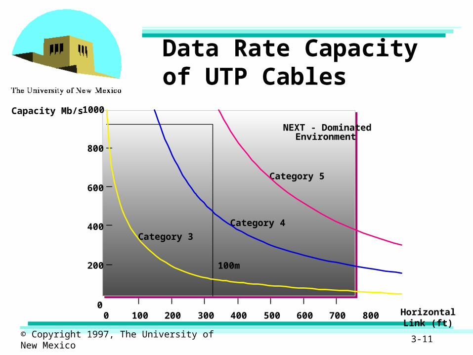
• EIA-568-A standard recognizes– category 3 UTP capable of 16MHz – category 4 UTP capable of 20 MHz– category 5 UTP capable of 100MHz
3-11© Copyright 1997, The University of New Mexico
Data Rate Capacity of UTP Cables
NEXT - DominatedEnvironment
Category 5
Category 4
Category 3
100m
8000 100 200 300 400 500 600 700
1000
800
600
400
200
0Horizontal Link
(ft)
Capacity Mb/s
3-12© Copyright 1997, The University of New Mexico
Transmission Medium
• Coaxial cable– hollow outer cylindrical conductor surrounding a single
inner wire– regularly spaced insulating dielectric hold inner
conductor in place– jacket or shield covers the outer conductor– diameter 0.4 to 1 inch– television distribution: CATV– long distance telephone transmission– short run computer I/O channels– LANs– better frequency characteristics, higher data rates, and
more immune to interference than twisted pair
3-13© Copyright 1997, The University of New Mexico
Transmission Medium
• Optical fiber– 2 to 124 um flexible medium– conducts and optical ray– core: innermost section; cladding: middle section
forms a plastic coating over the core; jacket: the outer most section covering the cladding
– data rates of 2Gbps over tens of km– significantly low attenuation– not susceptible to interference or crosstalk– used for: long haul, metropolitan, and rural trunks,
subscriber loops and LANs
3-14© Copyright 1997, The University of New Mexico
Transmission Medium
• Optical fiber– Multimode transmission
• rays entering the core reflect and propagate along the fiber
– Single mode transmission• radius of core reduced to one wavelength• only a single angle of reflection is allowed• provides superior transmission
– XMTR: light-emitting diode (LED) or injection laser diode (ILD)
– RCVR: photodiode or photo transistor
3-15© Copyright 1997, The University of New Mexico
Transmission Medium
• Wireless– terrestrial microwave– satellite microwave– broadcast radio– infrared– laser
3-16© Copyright 1997, The University of New Mexico
Transmission Medium
• Terrestrial microwave– requires line of sight– requires fewer amplifiers or repeaters– long haul telecommunication services– voice and TV transmission– point-to-point links between buildings
3-17© Copyright 1997, The University of New Mexico
Transmission Medium
• Satellite microwave– relays used to link ground stations– functions as an amplifier or a repeater– can provide point-to-point to point-to-multipoint
connectivity– television distribution– long distance telephone transmission– private business networks
3-18© Copyright 1997, The University of New Mexico
Transmission Medium
• Broadcast radio– omnidirectional– does not require complex antennas– antennas need not be precisely aligned– FM radio– VHF and UHF television– data networks
3-19© Copyright 1997, The University of New Mexico
Transmission Medium
• Infrared– XMTR/RCVR (transceivers) modulate non-coherent
infrared light– line of sight is needed– no frequency allocation is needed– provides point-to-point connectivity

3-20© Copyright 1997, The University of New Mexico
Cabling Systems Evolution
• 1980’s View, Dedicated Application Proprietary Wiring, Central Processing, Voice and Data Separate
• 1990’s View, Integrated Open Architecture Wiring System, Voice/Data/Image/Video
• Need for High-Speed Transmission, 100/155 Mbps and Higher, Require Significantly more Bandwidth

3-21© Copyright 1997, The University of New Mexico
Cable Systems Evolution
DCP
19751K
10K
100K
1M
10M
100M
1G
1980 1985 1990 1995 2000
Data Rate bps
EIA-232
StarLAN 1 IBM 3270
4M Token Ring
10BASE-T
TP-PMD
BasebandVideo
ATM
622 Mb/s
Year
16M Token Ring

3-22© Copyright 1997, The University of New Mexico
Cabling Systems Evolution
• Cable systems must be developed to address:
– Non Compatible
– Non Standard
– Conventional Type Wiring Plans
• Designed to ease the introduction of new computer systems, LANs and PBXs
3-23© Copyright 1997, The University of New Mexico
Cabling Systems Concerns
• Installing and Maintaining a Reliable Cable Plant is Essential to the Well-Being of Today’s Mission Critical LANs
• Category 5 UTP is Today’s Preferred Choice for LAN Cabling
• Why is Category 5 UTP the Best Bet for Horizontal Wiring?
• How Does it Handle 100/155 Mbps + Data Rates?
• How Do You Maximize the Performance of Your UTP Installation?
3-24© Copyright 1997, The University of New Mexico
Cabling Systems Concerns
• Voice: Wiring system placed by PBX vendor or telephony networks to all identified work locations
• Data: Wiring placed by data networks on an as needed basis
• Proprietary Application Media (Coax, Dual Coax, Shielded)
• Data Processing Systems - Mainframe (IBM 3270, IBM System 36/38 AS 400, etc..)
• PC - Stand alone
3-25© Copyright 1997, The University of New Mexico
Cabling Systems Concerns
• LAN electronics vendors estimate cabling problems account for 50% of all LAN failures and problems
• LAN Technology stated that 70% of downtime is attributed to cable related problems
• A Communications Week study in January 1992 Found network downtime cost small companies $3,200.00 per hour
• Infonectics Corporation study in October 1993 found network downtime cost Fortune 1000 companies an average of $62,500 per hour.
© Copyright 1997, The University of New Mexico 3-26
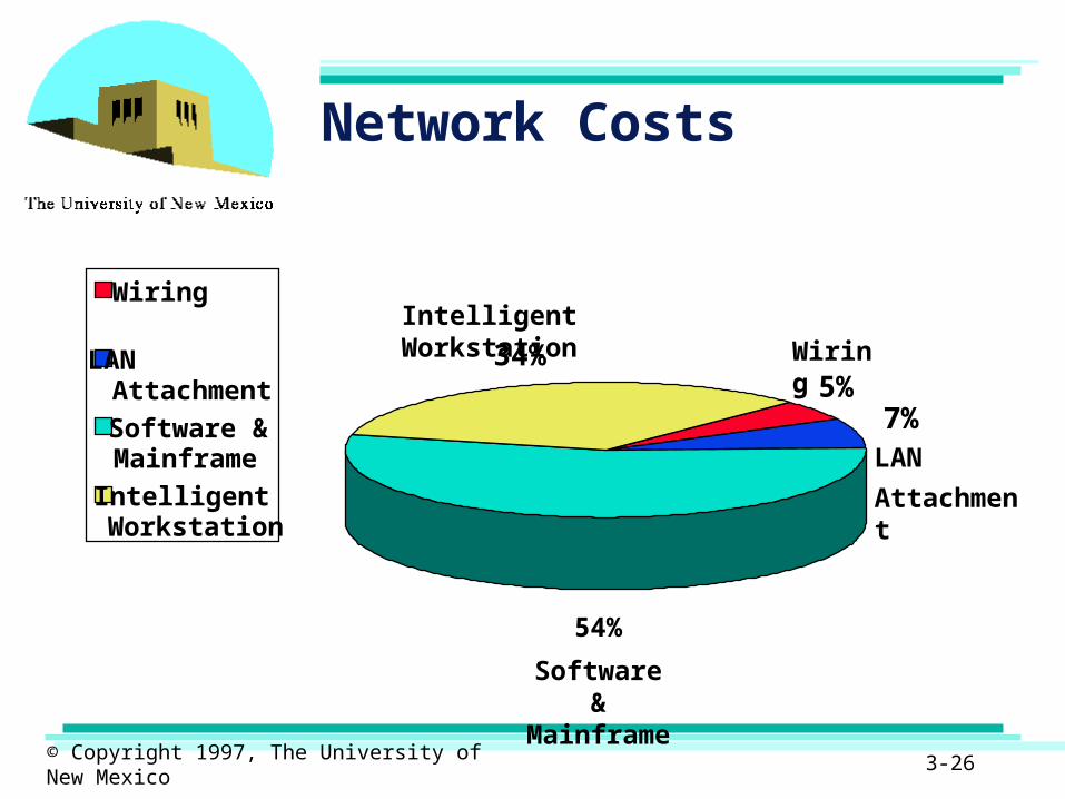
Network Costs
Wiring
Software & Mainframe
LAN
Attachment
Intelligent Workstation
5%7%
54%
34%
Wiring
LAN Attachment
Software &Mainframe
IntelligentWorkstation
3-27© Copyright 1997, The University of New Mexico
Cabling Systems Trends
• 100 Mbps over Copper, solutions for UTP already exist
• 100 Mbps over Fiber, Momentum has Slowed
• Fast Ethernet* 100 Mbps, on both CAT3 and CAT5 Cables
• ATM 155 Mbps do-able
• Theoretical limits of some manufactures CAT5 cables is more than 950 Mbps at 100 Meters.
3-28© Copyright 1997, The University of New Mexico
Cabling Systems Properties
• Open Architecture
• Integrated Distribution Plan
• Standards Compliant
• Cost Effective
• End-to-End Offering
• Full Functionality and Flexibility
• Manageable Growth
• Investment Protection
3-29© Copyright 1997, The University of New Mexico
Network cabling
• Networking supports transmission and reception of data.
• Network cabling provides the physical path for transmission and reception of data.

3-30© Copyright 1997, The University of New Mexico
Overview
• Transmission media typically used– Bounded media
• Electrical conductors (eg coaxial cable, twisted wire pairs).
• Optical conductors (eg Optical Fiber ).• Waveguides (air is the transmission medium but the waveguide confines or “binds” the transmission).
– Unbounded media• Transmission of electromagnetic waves or light through air or space.
3-31© Copyright 1997, The University of New Mexico
Bounded media
• Also known as guided media.• Bounded transmission media constrain
and guide communication signals.• Media using electrical signals are
– Single conductor– Paired cable and – Coaxial cable
3-32© Copyright 1997, The University of New Mexico
Bounded media ( Cont.)
• Media using light signals – Optical fiber
• Media using electromagnetic waves– Waveguides
3-33© Copyright 1997, The University of New Mexico
Single conductor
• A single conductor is used to provide a path for an electric current.
• The earth provides the return path ( since a circuit needs to be complete for current to flow).
• Today, used for short distances, like on a circuit board or on a silicon chip.
3-34© Copyright 1997, The University of New Mexico
Paired cable
• Two Conductors are used, with second conductor providing the return path for the signal current.
• Two cables can be – Open wire pair (parallel to each other ).– Unshielded twisted pair ( twisted ).– Shielded twisted pair (seldom used today).
• Open wires are susceptible to to cross talk and electromagnetic interference and are seldom used.
3-35© Copyright 1997, The University of New Mexico
Paired cable (Cont.)
• To avoid cross talk and interference the pairs of conductors are twisted.
• A twisted pair consists of 2 insulated copper wires twisted together.
• Usually number of these pairs are bundled together into a cable. Long distance cables may contain hundreds of pairs (eg telephone cables).
3-36© Copyright 1997, The University of New Mexico
Paired cable (Cont.)
• Twisting decreases the cross talk interference between adjacent cables by confining the electromagnetic field.
• Twisted pair can be used for short distances ( usually less than 10 miles).
• Longer distances require repeaters to regenerate the signal.
3-37© Copyright 1997, The University of New Mexico
Paired cable (Cont.)
• It has bandwidth limitations, when used over long distances.
• It is susceptible to noise since not all interference is eliminated.
• It is widely used for local telephone and data transmission.
3-38© Copyright 1997, The University of New Mexico
Paired cable (Cont.)
• It provides the “local loop” for telephone but the bandwidth is limited.
• It can support 155Mbps transmission over short (less than 30ft) distances.
• It is therefore widely used for network cabling within buildings (intrabuilding cabling).
3-39© Copyright 1997, The University of New Mexico
Coaxial cable
• Coaxial cable consists of two conductors.
• An inner conductor is completely sorrounded by an outer conductor.
• The two conductors are separated by high quality insulation.
• The outer conductor is sorrounded by a protective sheath.
3-40© Copyright 1997, The University of New Mexico
Coaxial cable (Cont.)
• Coaxial cables can be used for transmission of high frequency signals.
• Using frequency or time division multiplexing (FDM or TDM) many channels can be supported by single cable.
• It is widely used for cable TV.
3-41© Copyright 1997, The University of New Mexico
Coaxial cable (Cont.)
• It was widely used for (thick and thin cable) ethernets but it is being rapidly displaced by unshielded twisted pairs for this purpose.
3-42© Copyright 1997, The University of New Mexico
Waveguides
• A waveguide is a rectangular or circular pipe, usually made of some conductor such as copper.
• It confines and guides very high frequency radio waves between two locations.
• Waveguides are used for signals in the range of gigahertz (GHz) frequencies where twisted pair or even coaxial cables are not effective.
3-43© Copyright 1997, The University of New Mexico
Optical fibers
• Optical fiber is a thin, flexible glass or plastic fiber through which light energy is transmitted.
• An optical fiber is actually a waveguide that guides the propogation of optical frequency waves through total internal reflection.

3-44© Copyright 1997, The University of New Mexico
Optical fibers (Cont.)
• Since most of the data that need to be transmitted are in the form of electrical signals, these signals must be converted to light signals before they can be transmitted by optical fibers.
3-45© Copyright 1997, The University of New Mexico
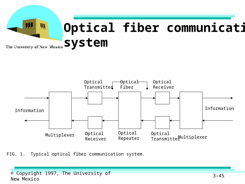
Information Information
OpticalTransmitter
OpticalReceiver
Multiplexer OpticalReceiver
OpticalRepeater
OpticalTransmitter Multiplexer
OpticalFiber
FIG. 1. Typical optical fiber communication system.
Optical fiber communication system
3-46© Copyright 1997, The University of New Mexico
Optical fibers (Cont.)
• Fiber optic transmission systems have transmitters which use– LED (Light emitting diode) used primarily for short
distances (< 2km) transmission or – LASER diodes used primarily for longer distance
transmission
to convert electrical signals to light signals.
3-47© Copyright 1997, The University of New Mexico
Optical fibers (Cont.)
• The receiver uses a photo diode to convert the light signals back to electrical signals.
• It offers large bandwidth.• Signal loss is very low.• Fibers are immune to electromagnetic
interference.
3-48© Copyright 1997, The University of New Mexico
Optical fibers (Cont.)
• A basic optical fiber consists of two concentric layers, the inner core and the outer cladding which has a specific refractive index lower than the core.
• There are 2 types of refractive index profiles, step and graded
• For a step profile fiber, the inner core’s refractive index is uniform, for a graded fiber, the profile inner core’s refractive index is not uniform.

3-49© Copyright 1997, The University of New Mexico
Characteristics of optical fiber

3-50© Copyright 1997, The University of New Mexico
Optical fibers (Cont.)
• There are 3 basic types of fibers– Multimode.– Single mode.– Multimode graded index.
• In multimode – Inner core diameter is relatively large (50 to 62.5
microns). – Light travels in different modes.
3-51© Copyright 1997, The University of New Mexico
Optical fibers (Cont.)
– Used for short or medium distances ( < 2km).– Cheap compared to other types.– Supports medium to high bandwidths.
• In single mode fibers– Inner diameter is very small, typically 0.8 to 1 micron.– Light travels in single mode.– Used for medium and long distances (> 2km).– More costly than multimode fiber.– Can support very high bandwidths (6 Gbps).
3-52© Copyright 1997, The University of New Mexico
Optical fibers (Cont.)
• In multimode graded index fibers– Core is relatively large but difficult to manufacture.– Properties are intermediate between single and
multimode fibers.– Because of difficulty in manufacture, such fibers are
seldom used in data networking.
3-53© Copyright 1997, The University of New Mexico
Unbounded media
• No physical connection is required.• Space or air is the transmission medium
for electromagnetic waves.• Source and destination can be static or
mobile.• Broad spectrum from low to high
bandwidth is available.• Can be quickly implemented.
3-54© Copyright 1997, The University of New Mexico
Unbounded media (Cont.)
• It is prone to interference.• Transmission spectrum has to be shared
and must be controlled to prevent interference in any given location.
• Different unbounded communication systems – Broadcast radio and television.– Terrestrial microwave.– Satellite.– Infra red.
3-55© Copyright 1997, The University of New Mexico
Network cabling
• Transmission media of interest for network cabling– Twisted pair– Coaxial– Fiber– Wireless
3-56© Copyright 1997, The University of New Mexico
Twisted pair
• Least expensive.• Flexible• Easy to install• Widely used.• There are two varieties
– UTP ( Unshielded twisted pair ).– STP ( Shielded twisted pair ).
3-57© Copyright 1997, The University of New Mexico
UTP
• Least expensive and popular.• It is light and flexible.• Easy to install.• It is not shielded by external
conductors.• It is subject to electromagnetic
interference and external noise.• Twisting minimizes electromagnetic
interference.
3-58© Copyright 1997, The University of New Mexico
UTP (Cont.)
• For data transmission 3 categories of UTP cabling can be used – Category 3 (cat 3 is for data rates upto 16 Mbps)– Category 4 (cat 4 is for data rates upto 20 Mbps)– Category 5 (cat 5 is for data rates upto 100 Mbps and
even 155Mbps for limited distances)
3-59© Copyright 1997, The University of New Mexico
UTP (Cont.)
• Cat 3 and Cat5 are used extensively• Cat3 is voice grade cable and widely
used for telephone.• It has 3 to 4 twists per foot.• Cat 5 is data grade cable and widely
used for data networking.

3-60© Copyright 1997, The University of New Mexico
UTP (Cont.)
• It has 6 to 12 twists per inch.• Tighter twisting provides better
performance but is more expensive.• Characteristic impedance of both cat 3
and cat 5 is 100 Ohms.• Cat5 is recommended, for data since it
can support higher bandwidths.
3-61© Copyright 1997, The University of New Mexico
STP
• Twisted pairs of copper wire are sorrounded with metallic braid or sheathing.
• Interference is reduced due to sheathing.• Characteristic impedance is 150 Ohms.• At lower data rates STP provides better
performance than UTP.• It creates less electrical noise.• It is more expensive.
3-62© Copyright 1997, The University of New Mexico
STP (Cont.)
• It is bulky.• Less flexible.• Installation is more expensive.• Difficult to work with compared to UTP.

3-63© Copyright 1997, The University of New Mexico
Coaxial cable
• It consists of single copper conductor at its center surrounded by a hollow cylindrical outer conductor, with the 2 conductors separated by a dielectric medium.
• Outer conductor provides a shield.• Coaxial cable is highly resistant to signal
interference because the electromagnetic field is confined between the inner and outer conductors.
3-64© Copyright 1997, The University of New Mexico
Coaxial cable (Cont.)
• Less susceptible to cross talk than twisted pair cable.
• It can support greater cable lengths between network devices than twisted pair cables.
• It can support much larger bandwidths than twisted cable pairs.
• It is bulky.

3-65© Copyright 1997, The University of New Mexico
Coaxial cable (Cont.)
• More difficult to install and work with than twisted pair cables.
• It is more expensive than twisted pairs.• Coaxial cable was used in thin ethernet
(10Base-2) and thick ethernet (10Base-5), but is now largely being replaced by cat5 UTP.

3-66© Copyright 1997, The University of New Mexico
Fiber optic cable
• An optical fiber is a thin (0.8 to 125 µm), flexible medium capable of conducting light.
• It has the ability to transmit signals over much longer distances than coaxial and twisted pair cables.
• Very high data rates (gigabits per second ) can be achieved over optical fiber.

3-67© Copyright 1997, The University of New Mexico
Fiber optic cable (Cont.)
• Theoretically 50Gbps are possible over fiber optic.
• Data rates of 4.8 Gbps over tens of kilometers have been demonstrated.
• Current dat rates are limited by the electronics and the optical transmitter/receivers.
• Optical fiber has the advantage of being thinner and lighter over coax or a bundle of twisted pair cables.
3-68© Copyright 1997, The University of New Mexico
Fiber optic cable (Cont.)
• It has lower attenuation than coax and twisted pair cables.
• Since it transmits light, the problem of electrical interference is eliminated.
• It is also immune to the environmental (eg. moisture, lightening) disturbances.

3-69© Copyright 1997, The University of New Mexico
Fiber optic cable (Cont.)
• The advantage of optical fiber over coax and twisted pair will be more compelling as the demand for greater bandwidth increases.
• It is highly secure medium, because it is difficult for any break to go undetected.
• The main disadvantage is it is very expensive
• Installation is expensive.
3-70© Copyright 1997, The University of New Mexico
Fiber optic cable (Cont.)
• Cannot tolerate small bending radius.• Difficult to work with because it is
delicate.
3-71© Copyright 1997, The University of New Mexico
Wireless
• Wireless media has the benefit of relatively inexpensive installation in an environment where users are mobile.
• It can also be beneficial in extending the network without rewiring the existing network.
• The 3 ways in use as of now are– Microwave– Spread spectrum– Infrared
3-72© Copyright 1997, The University of New Mexico
Microwave signals
• Uses a highly directional antenna to minimize interference.
• Frequencies used for transfer of information are dedicated.
• Usually suports point to point transmission.
• FCC regulates the bandwidth allocation.
3-73© Copyright 1997, The University of New Mexico
Microwave signals (Cont.)
• Has the disadvantage of using only part of the total available bandwidth.
• Microwave signals can cross through walls and physical barriers.
• Prone to interference from other sources of microwave signals.
3-74© Copyright 1997, The University of New Mexico
Microwave signals (Cont.)
• In general, it is relatively expensive but it may be the cheapest form of transmission over rough and mountainous terrain.
• Requires high power.• Data rates upto 500 Mbps are possible.• Exposure to microwave radiation may
be risky (health wise).
3-75© Copyright 1997, The University of New Mexico
Spread spectrum
• It doesn’t require FCC license.• In this method each node has a radio
transceiver.• Each node uses an antenna to send and
receive information.• The signal to be transmitted is spread
over a broad range of frequencies, so that signals look like noise.

3-76© Copyright 1997, The University of New Mexico
Spread spectrum (Cont.)
• The receiving station extracts its message, thus allowing a greater number of users to share the bandwidth.
• There are 2 ways to do this– Frequency hopping. – Direct Sequence.
3-77© Copyright 1997, The University of New Mexico
Spread spectrum (Cont.)
• In frequency hoping the transmission frequency is made to hop (change) rapidly. The receiver also hops in synchronism with transmitter and picks up the message.
• In direct sequence method, each bit is chipped into multiple bits using a bit pattern (thus spreading the signal over wider frequencies), with the help of same bit pattern receiver detects the bits.
• Data rates of upto 1-2Mbps are achievable.
3-78© Copyright 1997, The University of New Mexico
Infrared
• In this method infrared light is modulated by transmitter.
• Transceivers must be in line of sight either directly or via reflection from a light colored surface such as a ceiling of a room.
• Data rates of upto 20Mbps are possible.• No security or interference problems, as
infrared transmission does not penetrate the walls.
3-79© Copyright 1997, The University of New Mexico
Infrared (Cont.)
• License is not required.• Short range, point to point and
potential eye damage if exposed to IR rays are the main disadvantages of infrared transmission.
3-80© Copyright 1997, The University of New Mexico
Standards based cabling
• Unstructured cabling– No single standard is followed for interconnection– Low initial cost, more expenses later.– Difficulties in the long run with developing
technologies.– Difficulty in maintenance and scalability
• Structured cabling increases initial cost but can avoid the problems and future expenses.
3-81© Copyright 1997, The University of New Mexico
Standards based cabling (Cont.)
• Telecommunications industry and the users realized the need for cost effective, efficient cabling systems.
3-82© Copyright 1997, The University of New Mexico
Standards based cabling (Cont.)
• Electronic Industries Association (EIA), Telecommunications Industry Association (TIA) and other leading telecommunication companies worked cooperatively to create ANSI/TIA/EIA-568-A standard for commercial buildings.
• This standard defines structured cabling, a telecommunication cabling system that can support virtually any voice, imaging or data applications that an end user chooses.
3-83© Copyright 1997, The University of New Mexico
TIA/EIA 568-A standard
• EIA/TIA 568-A specifications address– Recognized media.– Topology.– Cabling distances.– User interfaces.– Cabling and Connecting hardware performance.– Installation practices.– Link performances.
3-84© Copyright 1997, The University of New Mexico
Cabling elements
• Horizontal Cabling.• Backbone Cabling.• Work Area (WA).• Telecommunications closet (TC).• Equipment Room (ER).• Entrance Facility (EF).

3-85© Copyright 1997, The University of New Mexico
Horizontal cabling
• It extends from the telecommunications outlet in the work area to the horizontal cross connect in the telecommunications closet.
Terminal
Work AreaTelecommunicationsCloset
3-86© Copyright 1997, The University of New Mexico
Horizontal cabling (Cont.)
• It includes – The outlet.– Horizontal cables.– Mechanical terminations and Patch cords (or jumpers)
that comprise the horizontal cross connect (each outlet in work area is connected to a horizontal cross connect in the telecommunications closet) .
3-87© Copyright 1997, The University of New Mexico
Horizontal cabling (Cont.)
• Specifications here are about– Proximity to EMI. – No. of outlets for each individual workarea.– UTP, STP and Fiber are recognized.– Coax is recognized but not recommended for new
cabling installations.– Horizontal cabling shall be configured in star topology.– Other such issues.
3-88© Copyright 1997, The University of New Mexico
Backbone cabling
• The backbone cabling system provides interconnections between – Telecommunication closets.– Equipment rooms.– Entrance facilities.– It also includes the vertical wiring between floors,
hence also known as vertical wiring.– Backbone also extends between buildings in a campus
environment.

3-89© Copyright 1997, The University of New Mexico
Backbone cabling (Cont.)
• The specifications include – Backbone cables.– Intermediate and main cross connects including
mechanical terminations.– Patch cords or jumpers used for backbone to backbone
cross connections.
• Recognized cables here are UTP, STP, Multimode and single mode fiber.

3-90© Copyright 1997, The University of New Mexico
Work area
• Work area specifications consist of – Cable connecting user station to wall plate.– Devices connecting the user station to the wall plate.– Work area wiring is typically UTP or STP.
3-91© Copyright 1997, The University of New Mexico
Telecommunication closet
• Also known as wiring closet.• One on each floor (typically, depending
on the floor space and special requirements number may vary).
• Standards complaint connecting hardware should be used.
• Specifications about short cables (patch chords) are made.
3-92© Copyright 1997, The University of New Mexico
Equipment room
• In large office buildings, there will be centralized equipment rooms to house servers, hubs, modems etc.
• It is the central interconnection point for network cabling.
• Main cross connections are specified here.
3-93© Copyright 1997, The University of New Mexico
Entrance facility
• It is the network entry point of the building.
• Within the network entrance facility, a cross connect device provides a termination point for all the cables.
• Interfaces are specified.• Interconnection for cross connect
devices and network devices are specified.
3-94© Copyright 1997, The University of New Mexico
Other specifications
• In addition to the cabling elements in TIA-568-A, there are specifications (connectors, cables, color coding etc) for – UTP cabling. – Fiber Optic cabling.– STP cabling.
3-95© Copyright 1997, The University of New Mexico
Design considerations
• Structured wiring is the way to go.• Highest quality connectors should be used.• While connecting twisted pair cables to
punch down blocks, care must be taken not exceed the bend radius of the cable (otherwise there can be signal leaks, leading to interference).
• Copper cables should not be run very close to power lines or parallel to them, otherwise there can be interference.
3-96© Copyright 1997, The University of New Mexico
Design considerations(Cont.)
• The end of the cable should not be untwisted more than needed, as this may result in excessive cross talk.
• Plenum grade cable must be used where there is a possibility of fire (like area above the suspended ceilings).
• NEC specifications for fire safety of cable installation should be followed .
3-97© Copyright 1997, The University of New Mexico
Design considerations(Cont.)
• While splicing fiber optic cable care must be raken to splice it perfectly at right angles.
• The connection of fiber to the optical connector must be perfect.
• Fiber should not be bent beyond its bending radius (several inches).
• Have patch cables as short as possible.
3-98© Copyright 1997, The University of New Mexico
Design considerations(Cont.)
• Label all the cables and connectors.• Maintain an accurate wiring plan.• Avoid using already installed telephone
cable (since it is not a data grade cable).