Embed Size (px)
Citation preview

© Boardworks Ltd 20051 of 29
These icons indicate that teacher’s notes or useful web addresses are available in the Notes Page.
This icon indicates that the slide contains activities created in Flash. These activities are not editable.
For more detailed instructions, see the Getting Started presentation.
© Boardworks Ltd 20051 of 29
Graphic Products ICT in Graphic Products

© Boardworks Ltd 20052 of 29
Learning objectivesL
earn
ing
ob
ject
ives
© Boardworks Ltd 20052 of 29
To understand what CAD and CAM systems are.
To learn about:a) CAD/CAM input devicesb) Computer software used in design and image manipulationc) CAD/CAM output devices.
To understand the benefits of using CAD and CAM.
To learn about other ways in which ICT benefits designers.

© Boardworks Ltd 20053 of 29
Computer Aided Design and Computer Aided Manufacture are terms used for a range of different ICT applications that can help in the design and manufacture of products.
COMPUTER AIDED MANUFACTUREA term used for manufacturing processes controlled
by computers.
COMPUTER AIDED DESIGNA computer aided system for creating, developing,
modifying and communicating design ideas.
CAD and CAM systems
© Boardworks Ltd 20054 of 29
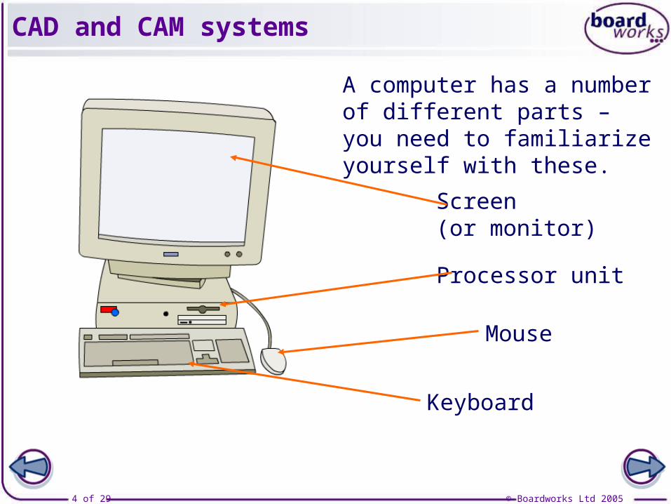
A computer has a number of different parts – you need to familiarize yourself with these.
Keyboard
Mouse
Processor unit
Screen(or monitor)
CAD and CAM systems

© Boardworks Ltd 20055 of 29
CAD and CAM systems involve inputs, processes and outputs.
INPUTS:
PROCESSES: Computer software
OUTPUTS:
Routers
Scanners
Digital cameras
PrintersProfile cutters
Clip art
CAD and CAM systems

© Boardworks Ltd 20056 of 29
Input devices allow you to capture or transfer images into a format that can be recognized by a computer.
The three most common formats are:
PICT files – (Picture file). One of the first formats for images.
TIFF files – (Tagged Image File Format). The most common format for images. It has a clear resolution so it is good for desktop publishing work.
JPEG files – (Joint Photographic Experts Group). This is a compressed file. Compressing files allows designers to use and transfer larger, more detailed images.
CAD and CAM input devices

© Boardworks Ltd 20057 of 29
CAD and CAM input devices

© Boardworks Ltd 20058 of 29
CD-ROMs – You can purchase CDs containing huge numbers of stored images. The images can be used straight from the CD, or downloaded onto your computer.
The Internet – The Internet gets bigger everyday. The information that you can find and download also increases daily. You can find images using search engines.
The images can then be copied into your work and edited for your purposes. However, remember that most images are owned by someone – copyright issues must be considered.
CAD and CAM input devices

© Boardworks Ltd 20059 of 29
Word processing packages –
The most common program is Microsoft Word.
Word allows you to copy, paste and format text. You can import photos and graphics and place them anywhere on the page.
Word processing packages are best suited to presenting documents that are mainly text, with a few illustrations.
There are a number of computer systems available that can help you to process your inputted images.
There are a number of other word processing programs, but Word is by far the most common.
Word processing and desktop publishing

© Boardworks Ltd 200510 of 29
Desk Top Publishing (DTP) –The most common DTP program is Microsoft Publisher. It allows you to manipulate text and images in a wider variety of ways than is possible in Word. It also has a number of Wizard Templates which can help you with the layout of your work.
Spreadsheets – The most common program is Microsoft Excel. Excel allows you to present information logically and rearrange data to suit your needs. Formulas can be added to help you manipulate figures.
Word processing and desktop publishing

© Boardworks Ltd 200511 of 29
There are many different graphics packages available.
Photoshop is a program for manipulating and editing photos.
ProDesktop is a program that is commonly used in schools. It allows you to carry out a variety of tasks including producing engineering drawings and 3D presentational work.
Graphics software allows you to:
Draw with great accuracy and scale drawings when needed.
Generate 3D virtual images, which can be viewed from any angle.
Generate working drawings from presentation images.
Render products to look exactly as you would like them, or add effect to images.
Graphics software

© Boardworks Ltd 200512 of 29
You can generate orthographic drawings using graphics software. You can create them from an existing image or screen shots.
Here is an example of a third angle orthographic projection done using ProDesktop.
Graphics software

© Boardworks Ltd 200513 of 29
You can make a virtual outcome using Computer Aided Design, which can then be used for modelling purposes.
ProDesktop allows you to actually see the product you are designing. You can rotate it and view it from different angles, allowing you to see flaws in your design before you actually make it.
Modelling with CAD

© Boardworks Ltd 200514 of 29
You can also render the product to make it look like it has been manufactured from different materials or with different finishes.
Modelling with CAD
© Boardworks Ltd 200515 of 29
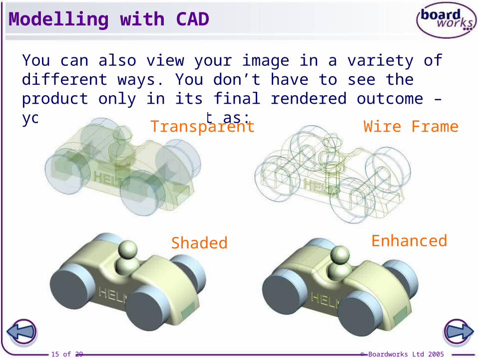
You can also view your image in a variety of different ways. You don’t have to see the product only in its final rendered outcome – you can also view it as:
Transparent Wire Frame
Shaded Enhanced
Modelling with CAD

© Boardworks Ltd 200516 of 29
In CAD and CAM systems, the output device is the machine that actually makes the product. Printers are the most commonly used output device.
Printers –
There are two different types of printer:
Inkjet printers – these use tiny jets of ink to create the image. They are cheap to buy, but the ink they use can be expensive.
Laser printers – these use toner powder instead of ink. They are expensive to buy, but can print images much faster, and are cheaper to run.
CAM output devices

© Boardworks Ltd 200517 of 29
Profile plotters – Profile plotters are similar to printers in that they create an image as instructed by a computer. However, a plotter draws the image with a pen, instead of creating it using tiny dots.
Profile cutters – Profile cutters accurately cut out words and images from thin sheet materials like card and vinyl. They are often used to make signs. You can also use them to cut out net designs and stencils accurately.
CAM output devices
This means it is more accurate than a printer.

© Boardworks Ltd 200518 of 29
Milling machines (routers) – These are computer controlled machines for making 3D shapes. The computer tells the cutter where to move to and the depth needed for the cut.
3-axis milling machines have been around for a while and can create most shapes. 4-axis machines allow for the creation of rotational objects such as bottles.
CAM output devices

© Boardworks Ltd 200519 of 29
Press play to see a clip of a 3-axis router in action.
A 4-axis router would be able to rotate the block as well.
CAM output devices

© Boardworks Ltd 200520 of 29
Stereolithography is an alternative method of creating a 3D shape quickly. A design on computer is communicated to the machine, which contains a tank of plastic resin.
Gradually the object is formed, a layer at a time.
The solid part is then lowered below the surface, and the laser creates a new layer on top of it.
A laser moves over the surface of the resin causing part of it to solidify.
Stereolithography

© Boardworks Ltd 200521 of 29
CAD and CAM systems

© Boardworks Ltd 200522 of 29
Computer aided design is becoming more and more popular. It is used by a wide range of people such as designers, engineers and architects. It allows you to:
create images or products and rotate them on the screen so that you can view them from different angles
draw images or products with accuracy and be able to scale them up or down without distortion
create repetitive areas of the product quickly by duplication
simulate the product’s function, so you can test its performance before it is made
store images on computer, so there is less paper waste.
CAD benefits

© Boardworks Ltd 200523 of 29
Computer aided manufacture is used by a wide range of people and industries. The computer controls the movement of the machine by issuing instructions. It allows you to:
work continually without needing breaks – the machine does not get tired
make fewer mistakes, as long as the computer has been programmed correctly
manufacture products in environments not suitable for people, due to hazards or toxins
maintain quality, as every product will be identical.
CAD benefits

© Boardworks Ltd 200524 of 29
The initial financial outlay at the start can be a lot higher when using CAD and CAM.
Staff need to be trained in how to use the new equipment. This could be very time consuming.
If the machinery breaks down, production could come to a standstill.
Machines cost money to run – they need electricity, take up space and require maintenance. A specialist may need to be hired to look after the CAD/CAM systems.
There are some drawbacks of CAD / CAM that have to be taken into consideration. Most are to do with cost.
Drawbacks of CAD/CAM

© Boardworks Ltd 200525 of 29
A good example is the Airbus A380. The different sections of the plane are built in different countries and then brought together and assembled. The Bristol Airbus factory is responsible for making the wings.
Modern technology allows designers to communicate designs via electronic transfer. This means that designers from all over the world can work together on the same product.
It also allows designers to communicate their designs to manufacturers without needing to meet them.
Electronic transfer of data

© Boardworks Ltd 200526 of 29
The designs for the plane have to be very detailed so that the sections will fit together exactly when the Airbus is assembled.
The Airbus A380 was assembled successfully and flew for the first time in April 2005.
The Airbus company used:
Computer software to test the design – they were confident that the A380 would fly before it was built
E-mail – to help designers and manufactures communicate
Videoconferencing technology – this uses webcams and telecommunications systems to allow people in many locations to contribute to a joint meeting.
Electronic transfer of data

© Boardworks Ltd 200527 of 29
As the World Wide Web gets bigger, its usefulness as a research and information tool increases.
There are a huge number of sites, and they are continually updated with the latest information.
The easiest way to access the World Wide Web is through search engines. A search engine is a site that searches the web for keywords that you enter.
Some common search engines are:
Google (there is a UK version, as well as a world version)
Ask Jeeves
Yahoo.
World Wide Web
Searching the internet can be a slow and frustrating process, but the amount of information available makes it a great way to research your graphic products.
© Boardworks Ltd 200528 of 29
Plenary

© Boardworks Ltd 200529 of 29
Key pointsK
ey p
oin
ts
© Boardworks Ltd 200529 of 29
CAD and CAM systems consist of inputs, processes and outputs.
CAD/CAM input devices include scanners, cameras and image libraries.
There are many software packages available which allow you to manipulate graphics using a computer.
CAD/CAM output devices include printers, plotters and routers.
There are drawbacks, as well as benefits, to using CAD and CAM.
The growth of the electronic transfer of data and the Internet have helped designers to research and communicate designs.