Embed Size (px)
Citation preview

ASTRO ENVELOPE FEEDER
AMC-2000-5
FOR
RYOBI 3302 / ITEK 3985 (2 COLOR)
INSTALLATION AND OPERATING INSTRUCTIONS
Copyright © 2015 Astro Machine Corporation
INTRODUCTION
Thank you for purchasing the Astro Envelope Feeder. It is fast, efficient, reliable, and is designed to give you many
years of trouble-free service.
Numerous built-in features of the Astro Envelope Feeder combined with state-of-the art technology make this unit
superior. Top load/bottom vacuum feed provides continuous printing of various sized envelopes, cards, and tags.
Uniquely designed conveyor board with its synchronized side guides and push guide provides accurate registration
for secondary color operations. Photoelectric sensor is the key element in the synchronization of the Envelope
Feeder to the Duplicator and is designed to give many years of virtually trouble-free operation.
Flexibility. Optional Auxiliary Installation Kit provides compatibility to additional presses or duplicators of the
same type. An optional Dual Stream Feed Kit is available for feeding different size envelopes simultaneously to
double your production needs.
SPECIFICATIONS*
VOLTAGE REQUIREMENTS: 115 VAC – 60 Hz – 10 A
OPTIONAL AVAILABILITY: 220 VAC – 50 Hz - 5 A
ENVELOPE DIMENSIONS: Minimum: 3" x 5" (7.6 x 12.7 cm)
Maximum: 11" x 16-1/4" (27.9 x 41.3 cm)
MAXIMUM FEEDING SPEED: Governed by Press
MACHINE DIMENSIONS: Width: 20" (50.8 cm)
Length: 37" (94 cm)
Height: 42" (106.7 cm)
Weight: 150 lbs. (68 kg)
AVAILABLE OPTIONS: Conveyor Delivery
Pulse Generator Kits
Dual Stream Feed Kit
* Manufacturer reserves the right to change specifications without written notice.
SAFETY PRECAUTIONS THIS EQUIPMENT PRESENTS NO PROBLEM WHEN USED PROPERLY. OBSERVE SAFETY RULES WHEN OPERATING FEEDER.
READ THIS MANUAL CAREFULLY AND FOLLOW RECOMMENDED PROCEDURES.
1. KEEP HANDS, HAIR, AND CLOTHING CLEAR OF ROLLERS, TAPES AND OTHER MOVING PARTS.
2. ALWAYS TURN MACHINE OFF BEFORE MAKING ADJUSTMENTS OR CLEANING MACHINE.
3. DISCONNECT POWER CORD WHEN MAKING ANY MACHINE ADJUSTMENTS OR PERFORMING ANY MAINTENANCE NOT COVERED IN THIS MANUAL.
CAUTION
THIS EQUIPMENT MUST BE CONNECTED TO A PROPERLY GROUNDED OUTLET. FAILURE TO DO SO CREATES A POTENTIAL DANGER OF ELECTRICAL SHOCK.
Page 1
PARTS LIST The following parts are included with this machine.
Check and identify all parts with those listed below:
A. ENVELOPE FEEDER 84-000-00
B. STAND WITH PUMP ASSEMBLY (See Pages 13 & 14)
C. PULSE GENERATOR ASSEMBLY 88-140-100
D. PLASTIC TIES (4) 123-0113
E. FRONT ENVELOPE GUIDE R/H 84-108-15
F. FRONT ENVELOPE GUIDE L/H 84-108-14
G. CENTER ENVELOPE GUIDE 71-140-13
H. REAR ENVELOPE GUIDE 84-108-20
I. LEVELING KNOB 80-108-22
J. LOCKING THUMBSCREW (4) 80-108-20
K. PAPER HEIGHT STOP 89-100-82
L. SHEET SEPARATOR (4) 71-109-05
M. SPRING 71-120-02
N. SUCTION CUP (4) 71-134-15
O. ALLEN WRENCH – 1/16” 123-0057
P. ALLEN WRENCH – 3/32” 123-0058
Q. FUSE, 2 AMP (FAST BLO) 123-0285
R. FUSE, 10 AMP (SLO BLO) 123-0090
S. SUCTION FOOT CAP (4) 123-0415
T. WHEEL CASTERS (4) (2) 123-0517, (2) 123-0521
U. SKID WHEEL – LONG (1) 86-125-46
Page 2
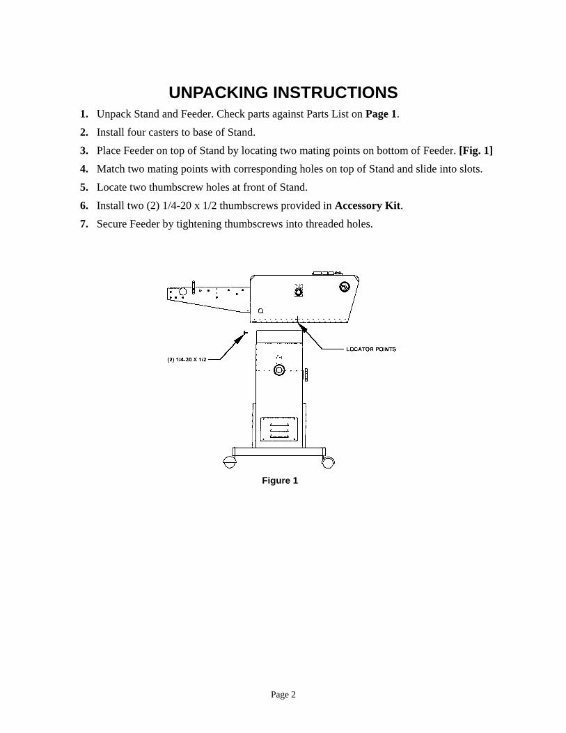
UNPACKING INSTRUCTIONS 1. Unpack Stand and Feeder. Check parts against Parts List on Page 1.
2. Install four casters to base of Stand.
3. Place Feeder on top of Stand by locating two mating points on bottom of Feeder. [Fig. 1]
4. Match two mating points with corresponding holes on top of Stand and slide into slots.
5. Locate two thumbscrew holes at front of Stand.
6. Install two (2) 1/4-20 x 1/2 thumbscrews provided in Accessory Kit.
7. Secure Feeder by tightening thumbscrews into threaded holes.
Figure 1
Page 3
INSTALLATION INSTRUCTIONS 1. Unplug Duplicator.
2. Remove Right Upper Cover from Duplicator.
3. Remove Chain Tensioner from Duplicator.
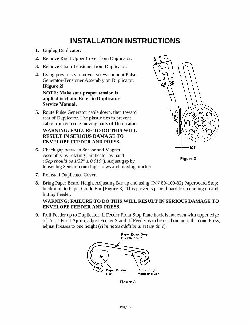
4. Using previously removed screws, mount Pulse
Generator-Tensioner Assembly on Duplicator.
[Figure 2]
NOTE: Make sure proper tension is
applied to chain. Refer to Duplicator
Service Manual.
5. Route Pulse Generator cable down, then toward
rear of Duplicator. Use plastic ties to prevent
cable from entering moving parts of Duplicator.
WARNING: FAILURE TO DO THIS WILL
RESULT IN SERIOUS DAMAGE TO
ENVELOPE FEEDER AND PRESS.
6. Check gap between Sensor and Magnet
Assembly by rotating Duplicator by hand.
(Gap should be 1/32" ± 0.010"). Adjust gap by
loosening Sensor mounting screws and moving bracket.
7. Reinstall Duplicator Cover.
8. Bring Paper Board Height Adjusting Bar up and using (P/N 89-100-82) Paperboard Stop;
hook it up to Paper Guide Bar [Figure 3]. This prevents paper board from coming up and
hitting Feeder.
WARNING: FAILURE TO DO THIS WILL RESULT IN SERIOUS DAMAGE TO
ENVELOPE FEEDER AND PRESS.
9. Roll Feeder up to Duplicator. If Feeder Front Stop Plate hook is not even with upper edge
of Press' Front Apron, adjust Feeder Stand. If Feeder is to be used on more than one Press,
adjust Presses to one height (eliminates additional set up time).
Figure 3
Figure 2
Page 4
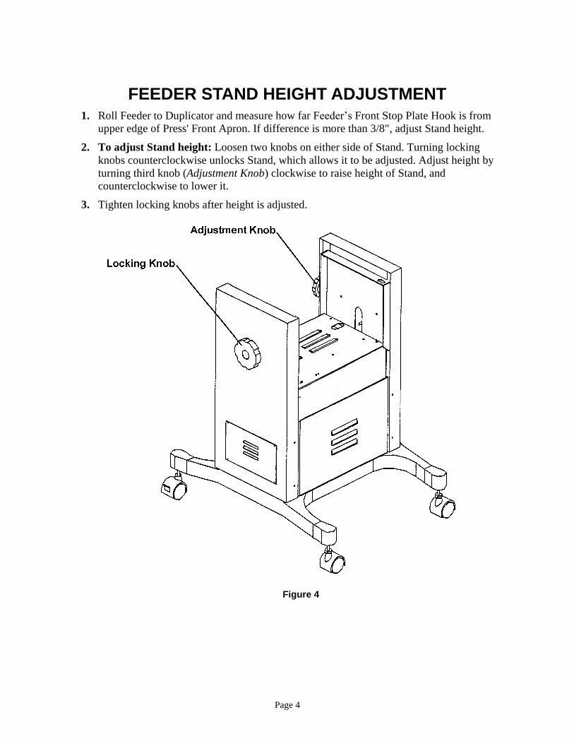
FEEDER STAND HEIGHT ADJUSTMENT 1. Roll Feeder to Duplicator and measure how far Feeder’s Front Stop Plate Hook is from
upper edge of Press' Front Apron. If difference is more than 3/8", adjust Stand height.
2. To adjust Stand height: Loosen two knobs on either side of Stand. Turning locking
knobs counterclockwise unlocks Stand, which allows it to be adjusted. Adjust height by
turning third knob (Adjustment Knob) clockwise to raise height of Stand, and
counterclockwise to lower it.
3. Tighten locking knobs after height is adjusted.
Figure 4
Page 5
CONTROLS
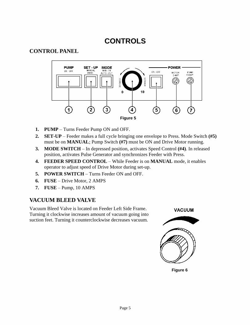
CONTROL PANEL
1. PUMP – Turns Feeder Pump ON and OFF.
2. SET-UP – Feeder makes a full cycle bringing one envelope to Press. Mode Switch (#5)
must be on MANUAL; Pump Switch (#7) must be ON and Drive Motor running.
3. MODE SWITCH – In depressed position, activates Speed Control (#4). In released
position, activates Pulse Generator and synchronizes Feeder with Press.
4. FEEDER SPEED CONTROL – While Feeder is on MANUAL mode, it enables
operator to adjust speed of Drive Motor during set-up.
5. POWER SWITCH – Turns Feeder ON and OFF.
6. FUSE – Drive Motor, 2 AMPS
7. FUSE – Pump, 10 AMPS
VACUUM BLEED VALVE
Vacuum Bleed Valve is located on Feeder Left Side Frame.
Turning it clockwise increases amount of vacuum going into
suction feet. Turning it counterclockwise decreases vacuum.
Figure 6
Figure 5
Page 6
OPERATING INSTRUCTIONS 1. Adjust Envelope Feeder Stand to height of Press' Front Feed Plate.
2. Hook Front Feed Plate on Envelope Feeder over bar on Press' Feeder.
Tighten clamp screw assembly securely.
3. Plug Pulse Generator into connector provided on Envelope Feeder.
Plug pump into receptacle provided on Envelope Feeder.
4. Plug Envelope Feeder into
wall receptacle.
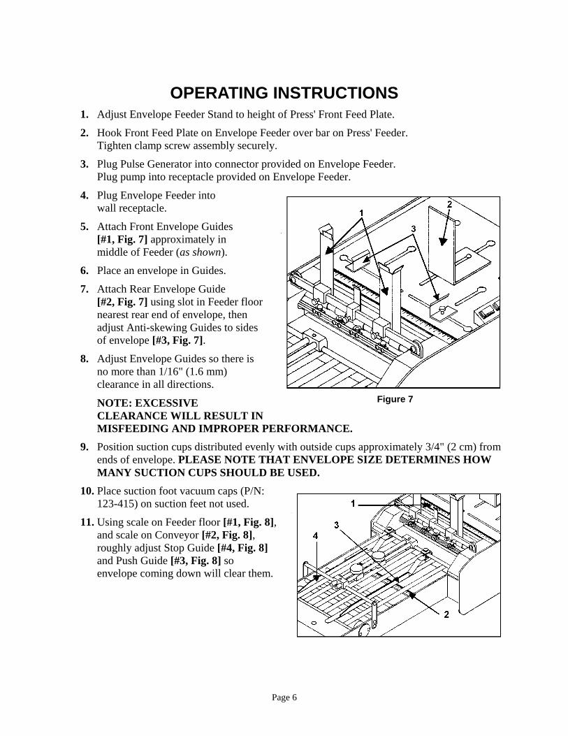
5. Attach Front Envelope Guides
[#1, Fig. 7] approximately in
middle of Feeder (as shown).
6. Place an envelope in Guides.
7. Attach Rear Envelope Guide
[#2, Fig. 7] using slot in Feeder floor
nearest rear end of envelope, then
adjust Anti-skewing Guides to sides
of envelope [#3, Fig. 7].
8. Adjust Envelope Guides so there is
no more than 1/16" (1.6 mm)
clearance in all directions.
NOTE: EXCESSIVE
CLEARANCE WILL RESULT IN
MISFEEDING AND IMPROPER PERFORMANCE.
9. Position suction cups distributed evenly with outside cups approximately 3/4" (2 cm) from
ends of envelope. PLEASE NOTE THAT ENVELOPE SIZE DETERMINES HOW
MANY SUCTION CUPS SHOULD BE USED.
10. Place suction foot vacuum caps (P/N:
123-415) on suction feet not used.
11. Using scale on Feeder floor [#1, Fig. 8],
and scale on Conveyor [#2, Fig. 8],
roughly adjust Stop Guide [#4, Fig. 8]
and Push Guide [#3, Fig. 8] so
envelope coming down will clear them.
Figure 8
Figure 7
Page 7
12. Place a small stack of envelopes in Guides.
13. Using adjusting thumbscrew, make sure right edge of Push Guide is perpendicular to
Front Stop Plate for accurate squareness.
14. Turn Feeder “ON”. Set Mode Switch on MANUAL and turn Speed Control clockwise so
Conveyor Tapes are moving slowly.
15. Turn Vacuum Switch “ON”.
16. Press SET-UP Switch momentarily. This activates Suction Cup Bar and brings down an
envelope. When envelope moves down Conveyor to Duplicator, make sure it clears Push
Guide and does not touch springs on Stop Guide.
17. Turn VACUUM Switch “OFF”. Press SET-UP Switch again. This activates jogging
mechanism. Adjust Jogger Guide so envelope just touches springs on Stop Guide.
NOTE: TOO MUCH JOG CAN AFFECT REGISTRATION.
18. Adjust Conveyor Tapes by moving Tape Guides (located under conveyor portion of
Feeder) while tapes are running slowly.
EXAMPLE: For No. 10 envelopes, use three (3) tapes. One over Stop Guides
(approx. 3/8" (1 cm) from springs), one over Push Guide (approx. 1/4" (6 mm) from
right edge) and one tape under Skid Wheel. For wider envelopes use additional tapes
as needed.
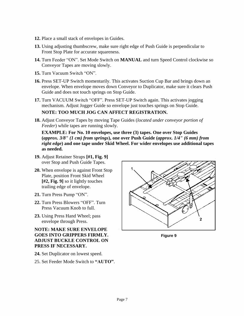
19. Adjust Retainer Straps [#1, Fig. 9]
over Stop and Push Guide Tapes.
20. When envelope is against Front Stop
Plate, position Front Skid Wheel
[#2, Fig. 9] so it lightly touches
trailing edge of envelope.
21. Turn Press Pump “ON”.
22. Turn Press Blowers “OFF”. Turn
Press Vacuum Knob to full.
23. Using Press Hand Wheel; pass
envelope through Press.
NOTE: MAKE SURE ENVELOPE
GOES INTO GRIPPERS FIRMLY.
ADJUST BUCKLE CONTROL ON
PRESS IF NECESSARY.
24. Set Duplicator on lowest speed.
25. Set Feeder Mode Switch to “AUTO”.
Figure 9
Page 8
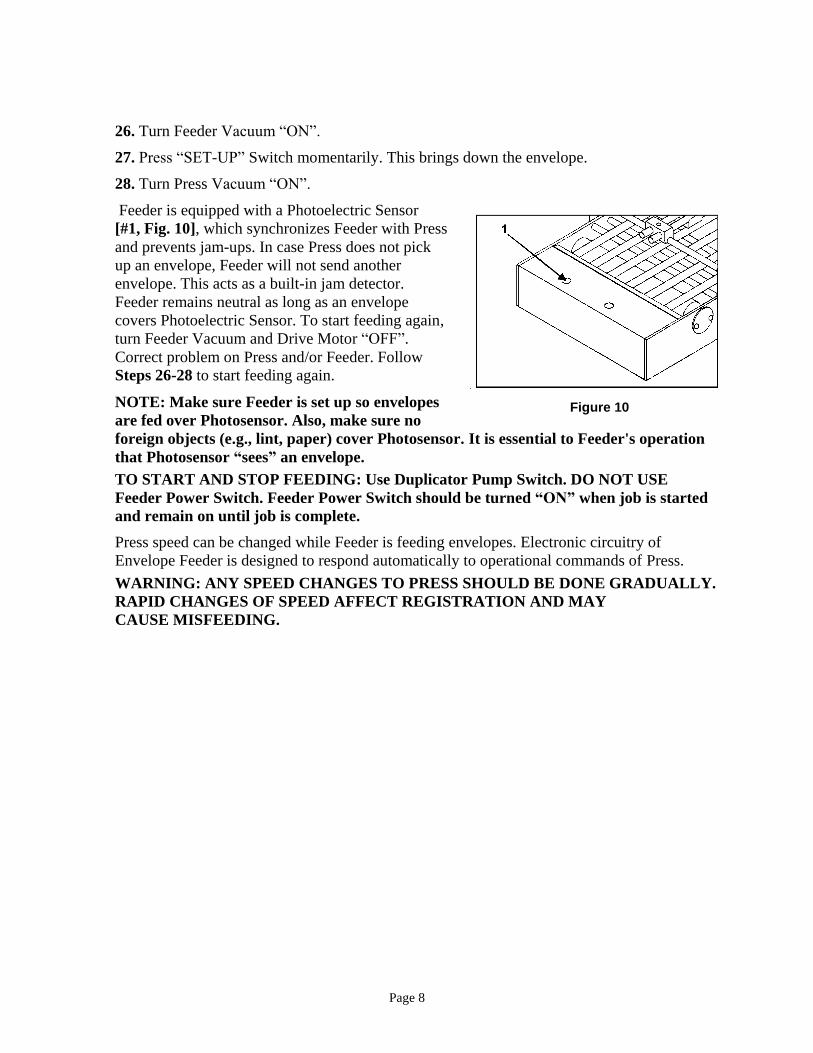
26. Turn Feeder Vacuum “ON”.
27. Press “SET-UP” Switch momentarily. This brings down the envelope.
28. Turn Press Vacuum “ON”.
Feeder is equipped with a Photoelectric Sensor
[#1, Fig. 10], which synchronizes Feeder with Press
and prevents jam-ups. In case Press does not pick
up an envelope, Feeder will not send another
envelope. This acts as a built-in jam detector.
Feeder remains neutral as long as an envelope
covers Photoelectric Sensor. To start feeding again,
turn Feeder Vacuum and Drive Motor “OFF”.
Correct problem on Press and/or Feeder. Follow
Steps 26-28 to start feeding again.
NOTE: Make sure Feeder is set up so envelopes
are fed over Photosensor. Also, make sure no
foreign objects (e.g., lint, paper) cover Photosensor. It is essential to Feeder's operation
that Photosensor “sees” an envelope.
TO START AND STOP FEEDING: Use Duplicator Pump Switch. DO NOT USE
Feeder Power Switch. Feeder Power Switch should be turned “ON” when job is started
and remain on until job is complete.
Press speed can be changed while Feeder is feeding envelopes. Electronic circuitry of
Envelope Feeder is designed to respond automatically to operational commands of Press.
WARNING: ANY SPEED CHANGES TO PRESS SHOULD BE DONE GRADUALLY.
RAPID CHANGES OF SPEED AFFECT REGISTRATION AND MAY
CAUSE MISFEEDING.
Figure 10

Page 9
OPERATING HINTS
A. Do not bend envelopes when setting Side Guides. Front and Rear
Guides must be snug against envelopes.
B. Form envelopes as required to maintain flatness to suction cups to
improve feeding consistency.
C. Be sure bottom envelope (in a stack of envelopes or tag stock),
rests on Sheet Separators.
D. Front Side Guides contain adjustable Sheet Separator Clips.
Clips project 3/32" (2.4 mm) beyond face of Guides. Adjustment
is seldom required.
1. Misfeeding may occur if clips extend too far under
envelopes. First increase vacuum and test run; then, if
required, move clip [#1, Fig. 11] to front using set screw behind them.
2. Double feeding may occur if clips are not under envelopes far enough. First decrease
vacuum and test run; then, if required, move clips to front.
Vertical position of clips is also adjustable. Loosen two screws [#2, Fig. 11] and position
bottom of clip flush with bottom of Guide.
Figure 11
Page 10
LUBRICATION INSTRUCTIONS
WARNING!
MACHINE MUST BE UNPLUGGED FROM ITS POWER RECEPTACLE WHILE PERFORMING LUBRICATION, MAINTENANCE, OR CLEANING PROCEDURES.
CAUTION
CARE SHOULD BE TAKEN TO KEEP LUBRICANTS FROM ELECTRICAL TERMINALS, SWITCHES, AS WELL AS ROLLERS, BELTS AND RUBBER PARTS.
When lubricating, pay particular attention to oil holes and all sliding parts.
NOTE: Residue of paper, dust, ink and other foreign materials MUST BE REMOVED
from gears, working levers, shafts and mechanisms before new lubricants are applied. This
prevents undue wear caused by abrasion from this residue material. Areas around or
adjacent to lubricated parts and surfaces MUST BE FREE of dust and foreign material.
LUBRICATION INTERVALS
Regular lubrication of oil ports (indicated by red) should be performed every 30 days on
machines that operate 30-40 hours per week.
LUBRICANTS
OIL: S.A.E. #20 non-detergent engine oil, or equivalent.
GREASE: Commercial lithium grease.
GENERAL LUBRICATION
1. Cams and Gears – Cleaned and lightly oiled.
2. Springs and Spring Levers – Greased lightly.
NOTE: Before greasing Springs and Spring Levers, existing lubricants MUST BE
REMOVED. Apply new grease sparingly – only hook ends of Spring, not on body.
3. Chain and Sprockets – Lubricate by using commercial lithium grease.
NOTE: To gain access to most lubricating points,
Front Cover Assembly MUST BE REMOVED.
Page 11
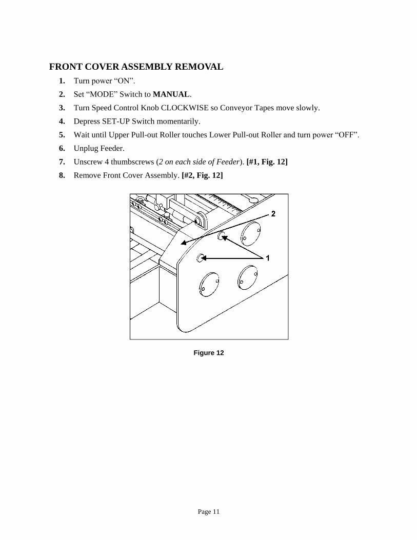
FRONT COVER ASSEMBLY REMOVAL
1. Turn power “ON”.
2. Set “MODE” Switch to MANUAL.
3. Turn Speed Control Knob CLOCKWISE so Conveyor Tapes move slowly.
4. Depress SET-UP Switch momentarily.
5. Wait until Upper Pull-out Roller touches Lower Pull-out Roller and turn power “OFF”.
6. Unplug Feeder.
7. Unscrew 4 thumbscrews (2 on each side of Feeder). [#1, Fig. 12]
8. Remove Front Cover Assembly. [#2, Fig. 12]
Figure 12
Page 12
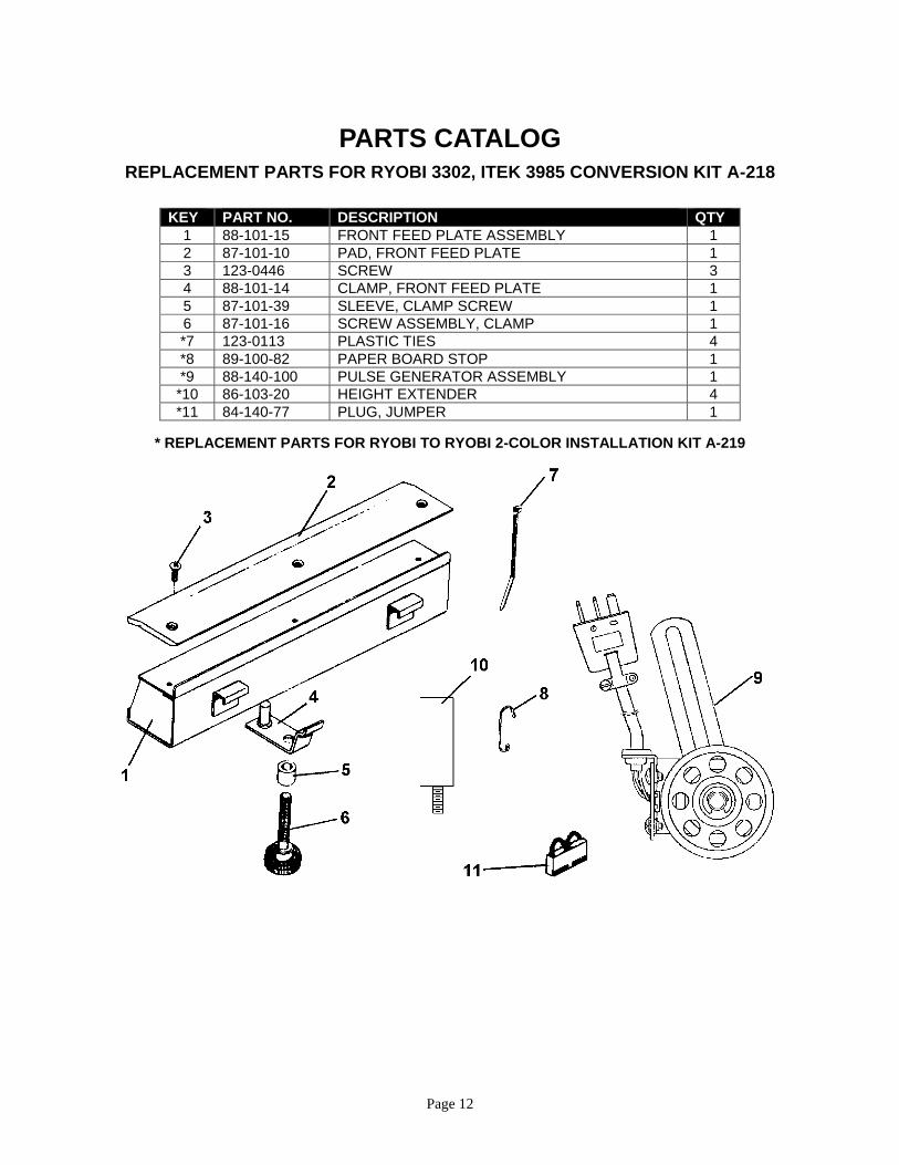
PARTS CATALOG REPLACEMENT PARTS FOR RYOBI 3302, ITEK 3985 CONVERSION KIT A-218
KEY PART NO. DESCRIPTION QTY
1 88-101-15 FRONT FEED PLATE ASSEMBLY 1
2 87-101-10 PAD, FRONT FEED PLATE 1
3 123-0446 SCREW 3
4 88-101-14 CLAMP, FRONT FEED PLATE 1
5 87-101-39 SLEEVE, CLAMP SCREW 1
6 87-101-16 SCREW ASSEMBLY, CLAMP 1
*7 123-0113 PLASTIC TIES 4
*8 89-100-82 PAPER BOARD STOP 1
*9 88-140-100 PULSE GENERATOR ASSEMBLY 1
*10 86-103-20 HEIGHT EXTENDER 4
*11 84-140-77 PLUG, JUMPER 1
* REPLACEMENT PARTS FOR RYOBI TO RYOBI 2-COLOR INSTALLATION KIT A-219
Page 13
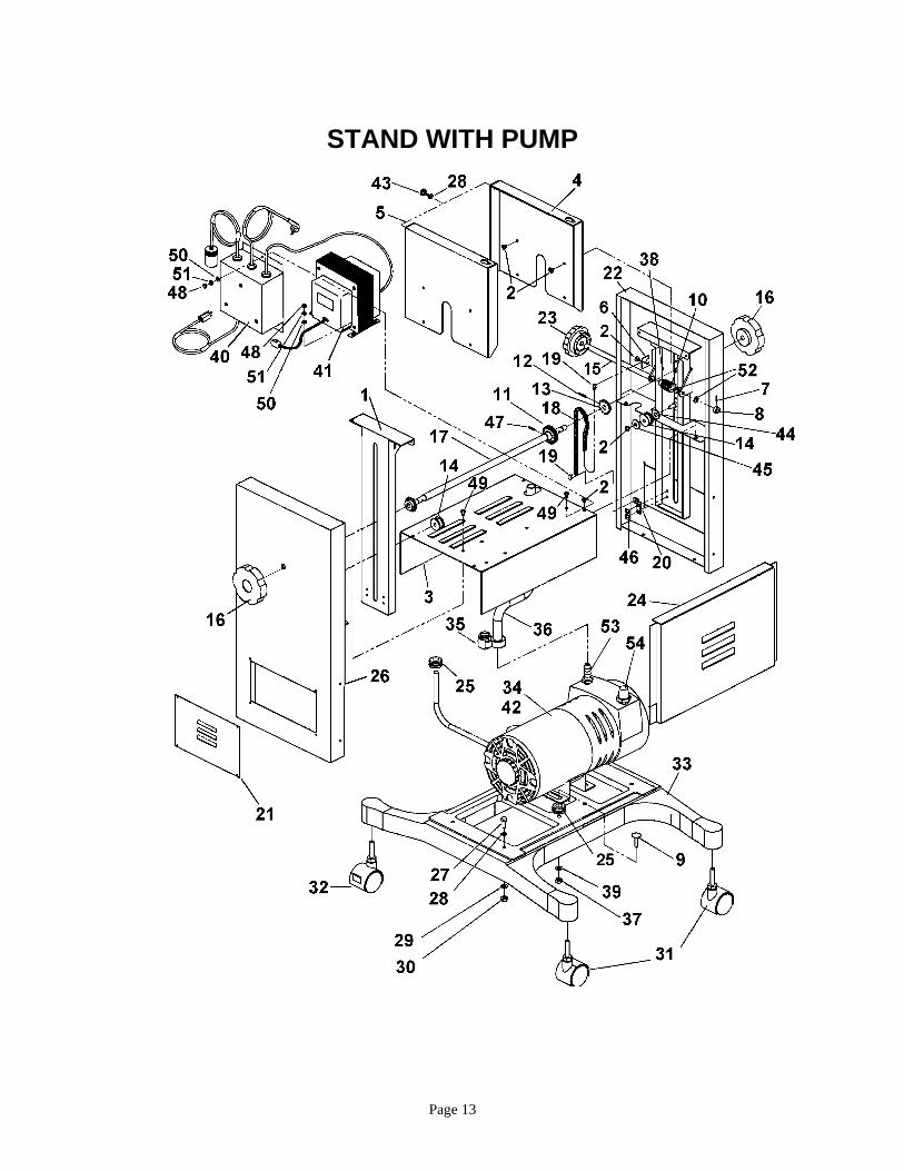
STAND WITH PUMP

Page 14
STAND WITH PUMP
KEY PART NO. DESCRIPTION QTY.
1. 156-102-18 ELEVATOR BRACKET (STANDARD) 2
1. 156-103-18 ELEVATOR BRACKET (LONG) 2
2. 123-0017 SCREW, 10-32 x 1/4 PHLPS TRUSS 32
3. 156-103-05 PANEL – BASE – PUMP COVER 1
4. 156-103-07 SIDE PLATE, R/H 1
5. 156-103-06 SIDE PLATE, L/H 1
6. 156-103-25 ELEVATOR BRACKET SUPPORT 2
7. 123-0695 SPRING PIN, 3/32 x1/2 1
8. 156-103-27 COLLAR 1
9. 123-0841 CARRIAGE BOLT, 5/16-18 x 1 4
10. 156-103-12 HELIX ANGLE WORM 2
11. 156-103-11 WORM GEAR, 20 TEETH 1
12. 123-0018 ROLL PIN, 1/8 x 3/4 – BLACK 3
13. 156-103-08 SPROCKET 25B13 2
14. 156-103-09 IDLER PULLEY 2
15. 156-103-21 WORM SHAFT 1
16. 123-0135 KNOB 2
17. 156-103-20 DRIVE SHAFT 1
18. 156-103-26 CHAIN, TRANSMISSION ROLLER 2
19. 123-0200 CONNECTING LINK, CHAIN 4
20. 156-103-23 ELEVATOR BRACKET SUPPORT 2
21. 86-103-04 COVER, SIDE PANEL 2
22. 156-103-03 SIDE PANEL, L/H 2
23. 123-0293 KNOB, HEIGHT ADJUSTMENT 1
24. 86-103-06 PUMP COVER, STAND 2
25. 123-0707 RUBBER GROMMET, 1/2 ID x 3/4 OD 1
26. 156-103-04 SIDE PANEL, R/H 1
27. 123-0143 SCREW, HEX 1/4-20 x 5/8 4
28. 123-0063 WASHER, 1/4 PLAIN-MOTOR & PUMP 8
29. 123-0064 LOCK WASHER, 1/4 8
30. 123-0054 NUT, HEX 1/4-20 8
31. 123-0517 CASTER, NON-LOCKING 2
32. 123-0521 CASTER, LOCKING 2
33. 86-103-31 BASE WELDMENT 1
34. 84-103-07 VACUUM PUMP ASSEMBLY, 115 V 1
35. 123-0131 CLAMP, HOSE 1
36. 84-106-41 HOSE, PUMP 1
37. 123-0051 NUT, 5/16-18 HEX 4
38. 123-0757 SET SCREW, 6-23 x 1/4 STD CUP PT 4
39. 123-0855 LOCKING WASHER, 5/16 4
* 40. 84-140-78 RELAY BOX 220V / 50 Hz 1
* 41. 123-0436 TRANSFORMER, 220V / 50 Hz 1
* 42. 84-103-10 VACUUM PUMP, 220V / 50 Hz 1
43. 56-108-22 THUMBSCREW 1
44. 123-0096 WASHER, PLASTIC 3/8 x 3/4 x 1/16 2
45. 123-0311 WASHER, PLASTIC 9/32 x 3/4 x 1/16 2
46. 123-0701 SCREW, 10-32 x 3/16 PH TRUSS HD 4
47. 123-0034 ROLL PIN, 1/8 x 5/8 1
*48. 123-0050 NUT, 10-32 x 5/16 HEX ZINC 6
*49. 123-0024 SCREW, 10-32 x 3/8 PH TRUSS HD MS ZINC 6
*50. 123-0237 STAR WASHER, #10 EXTERNAL 6
*51. 123-0262 WASHER #10 3/16 x 3/8 x 0.032 6
52. 123-0312 WASHER, PLASTIC 5/16 x 1/2 x 0.030 2
53. 123-0145 FITTING 1
54. AK840A FILTER/MUFFLER 1
** K247 SERVICE KIT, OLD STYLE PUMP
** K478 SERVICE KIT, NEW STYLE PUMP
** AK524 FELT, NEW STYLE PUMP ONLY
* 220V/0HZ ONLY **PARTS NOT SHOWN

Copyright © 2015 Astro Machine Corp. Elk Grove Village, Illinois 60007
07/01/2015
P/N: 200-AMC20005 Rev. A