Embed Size (px)
Citation preview
- 702 -
STATE-OF-TUE-ART FOR TUE STRUCTURAL DESIGN OF LOW-RISE HASONRY BUILDINGS IN TUE UK
N.J. Bright, MPhil, CEng, FICE, FIStructE, MIHT and C.A. Fudge, BSc, CEng, MIStructE Kingsway Group pIe, 289-293 High Holborn, London, WCIV 7HU, England.
ABSTRACT
In the UK, there is a demand for a simple design procedure for the s~z~ng
of masonry walls of low rise dwellings and similar buildings without calculations. Traditionally masonry walls have always been sized by simple prescriptive rules. Despite structural calculation methods being introduced in the last 40 years, the "rule of thumb" approach is still valid and usually produces the most economical solution for common low rise dwellings.
This paper gives a brief description of historical developments and discusses the full-scale testing substantiation and confirmation of the rules. A more detailed examination is given of the current position. Requirements of Building Regulations, Codes and Standards are reviewed and indications given of suitable materiaIs and constructions for residential buildings up to three storeys. The paper draws attention to the limitations of the scope of documents currently available.
INTRODUCTION
There is a universal desire to produce buildings which are both safe and economic to build and maintain. The difficulty is in obtaining the correct balance between these two functions, avoiding overdesign which produces an uneconomic solution, and underdesign carrying an unacceptable risk of failure. As a result of this, in the UK there is a demand for a simplified method of design for the sizing of walls for common types of low-rise dwellings and similar buildings.
In principIe there are potentially two types of simplified designo One route is to provide a set of rules whi c h are a simplified form of structural calculation. This type of ruI e may, however, tend to be conservative . The second route is that which has been adopted by the UK . Walls are sized by simple pres c riptive rules based on substantial expe rience without the need for rigorous c al c ulation.
For ma sonry con st ruc tions, such "rules of thumb" for low-rise housing have been available for some eight cen t uri es. Refinement. and modifications h ave take n place with changing buiIding techniques and materiaIs. By s i zin g the masonry using this method , s lender, more economic walls are ofte n pr o duced compared to solutions justified to current codes of pra c ti ce. Whilst this at first may appear unacceptable, one should consider the number of unquantified redundancies in a relatively small
- 703 -
box-like structure such as a house. Current structural design calculation methods in codes of practice for masonry do not permit an accurate measure of stress distribution and load share around such small, but complex, structures. This pape r reports on the state-of-the-art of masonry designed by simple rules for low-rise buildings in the UK.
HISTORICAL DEVELOPMENT OF SIHPLE RULES
Early requirements for minimum thicknesses of walls have been reported more extensively elsewhere [ref.l]. In London, for instance, rules for walls can be traced back to the Twelfth Century, although initial requirements appear to be for reasons other than structural. Consolidation of the rules commenced during the Seventeenth Century with Building Acts relating to room heights and wall thicknesses. By the mid Nineteenth Century, a series of Building Acts were available sizing walls for structural requirements, including a schedule giving the thickness of walls for various heights. Later rules went beyond low-rise dwellings to buildings of heights up to some 35 metres, although strict requirements were made to ensure the overall stability of the structure.
By the 1950s, a complete set of rules had been produced which differ little from those in use today. There was a need at this time to extend the rules to cover cavity walls which were becoming ever more popular. In addition, certain small, non-habitable buildings were provided with a less onerous set of conditions.
Building Regu1ations, which applied generally throughout England and Wales, were formulated in the mid 1960s [ref. 2] . A series of "schedules" was produced giving ways of satisfying the general criteria of designo One such was "Schedule 7 rules for satisfying requirements as to structural stability of certain walls " .
The Building Regulations 1985 for England and Wales [ref.3) took Schedule 7 of the old Regulations and transformed the recommendations into "Approved Documents A". During this stage no technical changes were made. Concurrently, however, the UK governrnental departments dealing with building regulations indicated that they would prefer to look to the availability of suitable documents from other sources. Since there was a general desire to go beyond the old Schedule 7, the Governrnent indicated to the British Standards Institution that should a document become available, the existing simple rules could be replaced. It was stressed that such a document should be acceptable to the industry.
A NEW BRITISH STANDARD
In the early 1980s, work began not only to produce a document with simple rules for masonry [ref. 4), but extended to recommendations covering the whole of the structural design for low-rise buildings. Initially, four parts of the code of practice were envisaged.
a) Stability, site investigation, foundations and ground floor slabs b) Hasonry walls c ) Timber floors and roofs d) Concrete suspended floors.
- 704 -
The level of the code is aimed at those with expertise in building construction, but not necessarily in structural engineering design o
For masonry, the task began in earnest in 1985. With simple rules having been in operation for many decades, it was soon decided that no fundamental changes were required. For this reason it was agreed to prepare a draft based on the documentation available, i.e. Schedule 7 of the Building Regulations for England and Wales. At the same time the Authorities in both Scotland and Northern Ireland were keen to harmonise their documents. A comparison of the various publications showed that they were not, on the whole, dissimilar . Thus the aim was to update and modify where necessary the existing working practice.
The justification for the mino r changes carne from:-
(a) experience of building performance over many years (b) research projects (c) calculations using current codes of practice .
Before examining the details of the recommendations and their recent changes, it is worth looking at the practical justification for the rules.
PRACTICAL EVIDENCE JUSTIFYING THE RULES
A vast proportion of the houses built in the UK have had their walls sized using the simple rules . But, as we know, these constructions cannot be justified by rigorous calculations to other design codes. One might expect, therefore, to have a high element of risk attached to such buildings. It is possible that in some cases the wrong materials may be used and the workmanship may be sub-standard. In such cases, it would be reasonable to expect local failures and damage. Yet even failures due to such causes are rare in the extreme. There is no evidence to support any suggestion that the rules are unsafe.
Many of these buildings have been tested in extreme adverse weather conditions. In recent times, many parts of the UK have been subjected to wind pressures in excess of those which would normally be expected to occur in the lifetime of the structure. Such gales and storms have certainly caused damage, but this has in general been associated with the lifting of roofs or impact damage from falling trees, etc. In the older housing stock, built prior to amendments for the tying of gable walls and with less robust chimneys, a few isolated failures occurred. No inherent design fault could be found with those buildings constructed using the most up to date version of the rules .
Similarly, as far as vertical loading is concerned, due to masonry overstress are virtually unheard of. that have occurred, due to vertical loading the s tabl e whilst floors and roofs have failed under overload above any design requirement .
collapses in dwellings Of the rare incidents
masonry has remained conditions of extreme
Perhap s nne of the most significant pieces of work to be carried out was an experimental programme carried out in the early 1980s. Whilst the rules had stood the test of time, changes in building construction and materials led to some concern as to overall stability. The preceding years had seen a trend away from heavyweight construction to a less
- 705 -
robust, slender form of construction. In the roof the change from traditional timber rafter and purlin construction to trussed rafter (lighter) timber structures significantly altered the load distribution on walls. The walls themselves had changed from solid brickwork to cavity construction usually with a lightweight blockwork inner leaf. Instead of building in floor and roof elements, the trend had been to use metal straps and ties instead. These modifications to house constructions, along with modern developments in layout, led to a full scale house testo
The shell of a full-size semi-detached domestic house was constructed in a structural laboratory. A full report of the construction can be found elsewhere [ref.5). Whilst using where possible the minimum sections and strengths allowed by the rules, the construction also took into account prac tica 1 cons idera t ions . Loads we re app lied which could s imulate both vertical live loads and lateral wind pressure. In summary, the house successfully sustained loads which exceed those generally applied to domestic constructions. Furthermore, it appeared that the recommended connections between floor and walls given in the Regulations were adequate and conservative.
It is on the basis of full scale laboratory testing and substantial practical experience that the "rules of thumb" have been justified.
DETAILED EXAHINATION OF THE LATEST UK RULES
As with all rules of this type, they have to be comprehensive enough to enable a satisfactory design to be made, but simple enough to be usable. The intention, therefore, is for the rules to be used by those with expertise in building construction, but not necessarily in structural engineering designo If the limitations are followed and adhered to, there is no need for specialist advice.
The worst combination of circumstances likely to arise is taken into account in the guidance. For this reason, it is considered appropriate to take a minor departure from the rules. This can be on the basis of judgement and experience or may be shown to be adequate by calculation in respect of the aspect of the wall which is affected by the departure.
Current UK rules exist semi-detached and terraced more than three storeys addition, rules exist for garages, porches etc.
for low-rise housing comprising detached, houses and flats without common access of not above ground for domestic occupation. In some small non-residential buildings such as
Limitations on the Building
There are a number of limitations which apply to the building, rather than appl yi ng to individual walls. To limit the loads coming from floors and roofs, allowable types of cons tructions are listed. These are generally of the type commonly utilised in the UK , such as timber trussed rafter roofs anel floors of timber or precast concrete. Vertical imposed loads arp general ly limited to a value of 1.SkN/m z which covers the classes of residpntial occupancy and self-contained dwelling units. The rules have also been written to cover the case of the maximum snow load likely to occur during the lifetime of the building. Lateral imposed loads are simply taken care of for both forces due to earth pressure and to wind
- 706 -
pressure. Walls are allowed to retain a maximum height of earth of 1m, but the thickness of the wall has to be at least a quarter of the retained height. For wind pressure, a limiting value of approximately 1.2kN/m Z is used. Recent ly, the guidance on this ma t ter has been further s impl if ied by giving the maximum heights of building allowed within areas across the UK. A wind speed map has been developed to give a reasonable return period. There is, however, an overriding limitation that no part of a wall or roof should be higher than 15m above the lowest adjacent ground leveI.
Other limiting factors are applied to various elements of the construction. For example, the maximum floor area for stability between four structural walls is of the order of 70m 2 • A maximum clear span of any roof and of any floor is set at 12m and 6m respectively. There is also guidance giving conditions relating to the building size and shape in order to achieve adequate stability against wind forces .
As far as individual walls are concerned, guidance is given on their overall size. In general, the maximum length of loadbearing wall between vertical lateral supports, for example between supporting walls, piers or returns etc., should be 9m. Most of the guidance is applicable to storey heights of less than 2.7m and walls should not in general contain openings having a clear span of greater than 3m.
Once a designer has checked the proposed building against these general overall dimensions, it is then possible to size the thickness of the masonry walls.
Determination of the Wall Thickness & Strength
For buildings which satisfy the general criteria given in the guidance, the walls of the building can be simply sized. In general, the recommendations allow solid walls of 190mm to be used as the externaI walls and walls between two adjacent dweIlings. Alternatively, cavity walls may be constructed using two Ieaves of 90mm with cavities ranging from 50 to 150mm. An overriding factor is that walls thickness should be at least l/16th of the height between horizontal restraints.
InternaI non-loadbearing walls are allowed to have a minimum thickness of 75mm, provided that they are adequateIy restrained at the head.
The minimum thickness of internaI loadbearing walls is generally in the order of 90mm. However, where a wall supports the upper two storeys in a three storey building, the thickness is increased to 140mm.
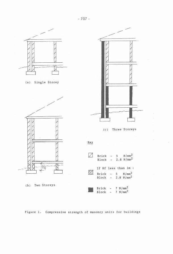
The minimum compressive strength of masonry units for various locations is shown in figuré 1. These values are based on test methods used in UK product standards [ref.6, 7, 8) and may not give the same vaIues obtained from test method s carried out in other countries. It should be noted that if the externaI wall is of solid construction, the masonry units should have a compressive strength at least equal to that shown for the inner leaf o f a c avity wall in the same position. An additional point to note throughout the recommendations, is that the strengths, thicknesses etc. are those adequate for structural designo However, the guidance described in the documents is not intended to cover other considerations such as fire resistance, thermal and sound insulation, resistance to damp penetration and durabiIity.
- 707 -
(a) Sing1e Storey
(c) Three Storeys
~
lZl Brick 5 N/nun2
B10ck 2.8 N/nun2
If Hf 1ess than 1m :
~ Brick 5 N /nun2
B10ck 2.8 N/nun2
(b) Two Storeys N/nun2 • Brick 7
B10ck 7 N/nun2
Figure 1. Compressive strength of masonry units for buildings
- 708 -
OTHER CRI TERIA ASSOCIATED WITH THE HASONRY WALL
One of the developing areas of masonry design has been that of concentrated loading owing to lintel bearings. Traditionally, it has in general been allowed to size walls on the basis of a minimum bearing length of 150mm. This approach is satisfactory for small span buildings with lintels spanning in the plane of the wall. More recently, however, the guidance has been modified to cover more extensively cases where concrete floors are used and cases where the lintel is spanning at right angles to the wall.
With the vast amount of cavity walling built in the UK, there is a need to consider the spacing and type of cavity wall ties. Usually, the leaves of a cavity wall should be tied together by ties embedded to a minimum depth of 50mm at a maximum spacing of 900mm horizontally and 450mm vertically (density of 2.5 ties/m Z ). Additional . ties are provided within 225mm of alI openings and at any unreturned edge, including roof lines, so that there is at least one tie for each 300mm of height or length of the opening. The guidance given in the documents also specifies the type of wall ties to be used, smaller cavities of 50mm normally requiring a fairly flexible type.
Perhaps one of the most important sections in the design documents is that of lateral restraint and layout of supporting walls. Once the wall has been sized and its strength determined, the building must be re-examined to check overall stability.
The ends of every loadbearing wall must be bonded or otherwise securely tied throughout the full height of the wall by some other form of support. This could be another supporting wall, pier or chimney, for example. Long walls may be provided with intermediate supports, effectively dividing the wall into distinct lengths. Each .of these lengths can then be defined as a structural wall in terms of the recommendations given.
The position and size of openings or recesses in a supporting wall should not impair the vertical support which is being provided by that wall. General rules are therefore given which limit the sizes of openings, etc. close to wall junctions.
Similarly, in a supporting wall, the number, size and position of openings and recesses should not impair the stability of that wall. Hence, most guidance generally allows openings up to a maximum width of 3m. Specific guidance is also given to limit the total length of openings in any one wall. To enable a designer to determine an adequate strength of masonry be tween two adj acent openings, s imple guidance i s gi ven. This usually takes the form of summing the lengths of the openings and dividing by a given factor: the resultant length is the minimum size of masonry to be prov ided.
Chases should be kept to a minimum and not be so positioned as to impair the s tability of wall, particularly where the masonry units are not solid units. Th e guidance generally limits vertical chases to a maximum of one third of the wall thickness. Horizontal and diagonal chases should be avoided if possible but in any case are limited to a maximum of one sixth of the thickness of the wall (or a leaf in the case of a cavity wall).
- 709 -
Walls in each storey of a building should extend to the full height of that storey, and have effective horizontal lateral supports to restrict movement of the wall at right angles to its plane. Floors and roofs should a c t to transfer lateral forces from walls to supporting walls, piers, chimneys, etc. and be secured to the supporting wall by effective connections. General guidance on these connections is a1so given in the documents associated with simple rules [ref . 9].
SÚHHARY
The general guidance reported in this paper along with the more specific requirements for aspects of design, allows UK designers to size low rise dwellings without calculations. This" rule of thumb " approach continues to be used extensively to produce buildings which are both safe and economic to build and maintain.
REFERENCES
(1) Bright N.J. and Fudge C.A., Historical Development of Simple Rules for Masonry Design, The Proceedings of the 8th IBMac Conference, Dublin, 1988 pp 1417-1425.
(2) Department of the Environment, The Building Regulations 1965, SI 1373, HMSO, London, 1966 .
(3) Department of the Environment, The Building Regulations 1985, Approved Documents A, HMSO, London, 1985.
(4 ) Document 89/12635, Draft BS 8103 Structural Design of Buildings: Part 2, Code of Practice for Masonry Walls, Standards Institution, London, 1989.
Low-Rise British
(5) Edgell G.J. and de Vekey R.C., The Robustness of the Domestic House, Part l:Compressive Loading Tests on Walls, Part 2:Wind Suction Tests on Gable Walls, British Ceramic Research Limited, Stoke-on-Trent, Technical Notes 350 (1983) and 364 (1985).
(6) BS 187 Specification for Calcium Silicate (sandlime and flintlime) bricks, British Standards Institution, London 1978 (1987).
(7) BS 3921 Specification for Clay Bricks, British Standards Institution, London, 1985.
(8) BS 6073 :Precast Concrete Masonry Precast Concrete Masonry Units, London, 1981 (1984).
Units:Part I, Specification for British Standards Institution,
(9) BS 8103: Structural Design of Low-Rise Buildings: Part I, Code of Practice f or Stability, Site Investigation, Foundations and Ground Floor Slabs for Housing, British Standards Institution, London, 1986.


![Punit Pandey - hindilok.com · tUe okj] tUe frfFk] tUe u{k=] tUe ;ksx rFkk tUe dj.k bu ik¡pksa dks feykdj iapkax Qy dh x.kuk dh xbZ gSA tUe ds le; mijksä lHkh ik¡pksa dkjdksa dks](https://img.pdfslide.us/doc/110x75/5e075a9967b7f075a46f6112/punit-pandey-tue-okj-tue-frffk-tue-uk-tue-ksx-rfkk-tue-djk-bu-ikpksa.jpg)