Embed Size (px)
Citation preview
MCA Combination Series
Residential Units
Installation and Operation Manual
MASTERWater Conditioning Corp.Water Conditioning Corp.Water Conditioning Corp.Water Conditioning Corp.
February 2011
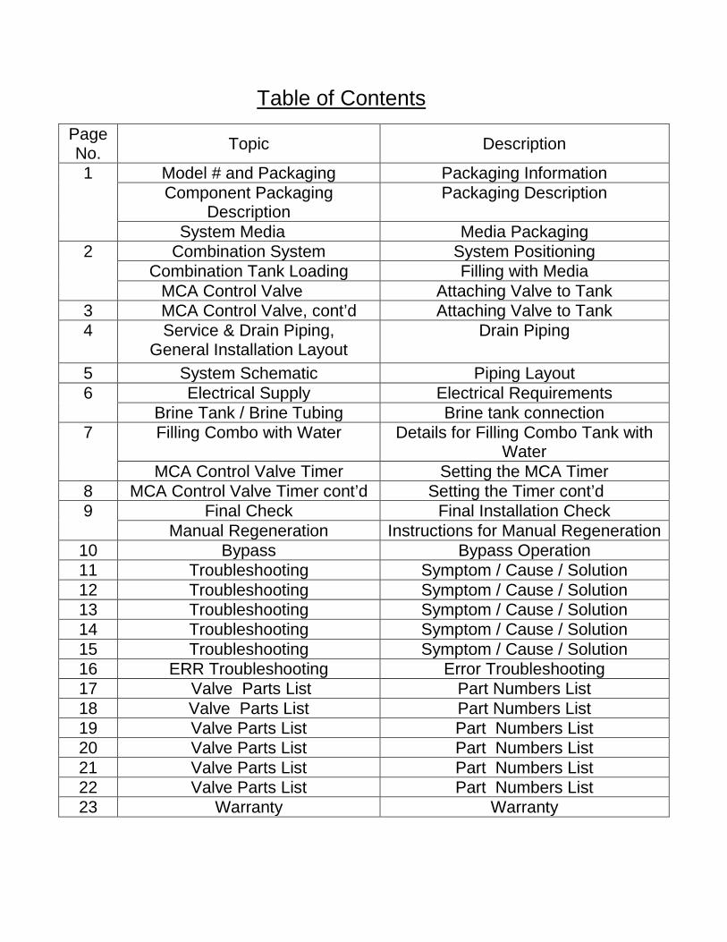
Table of Contents
Page No. Topic Description
1 Model # and Packaging Packaging Information Component Packaging
Description Packaging Description
System Media Media Packaging 2
Combination System System Positioning Combination Tank Loading Filling with Media
MCA Control Valve Attaching Valve to Tank 3 MCA Control Valve, cont’d Attaching Valve to Tank 4 Service & Drain Piping,
General Installation Layout Drain Piping
5 System Schematic Piping Layout 6 Electrical Supply Electrical Requirements
Brine Tank / Brine Tubing Brine tank connection 7
Filling Combo with Water Details for Filling Combo Tank with Water
MCA Control Valve Timer Setting the MCA Timer 8 MCA Control Valve Timer cont’d Setting the Timer cont’d 9 Final Check Final Installation Check
Manual Regeneration Instructions for Manual Regeneration 10 Bypass Bypass Operation 11 Troubleshooting Symptom / Cause / Solution 12 Troubleshooting Symptom / Cause / Solution 13 Troubleshooting Symptom / Cause / Solution 14 Troubleshooting Symptom / Cause / Solution 15 Troubleshooting Symptom / Cause / Solution 16 ERR Troubleshooting Error Troubleshooting 17 Valve Parts List Part Numbers List 18 Valve Parts List Part Numbers List 19 Valve Parts List Part Numbers List 20 Valve Parts List Part Numbers List 21 Valve Parts List Part Numbers List 22 Valve Parts List Part Numbers List 23 Warranty Warranty
1
Installation and Operating Instructions for MCA CONTROL
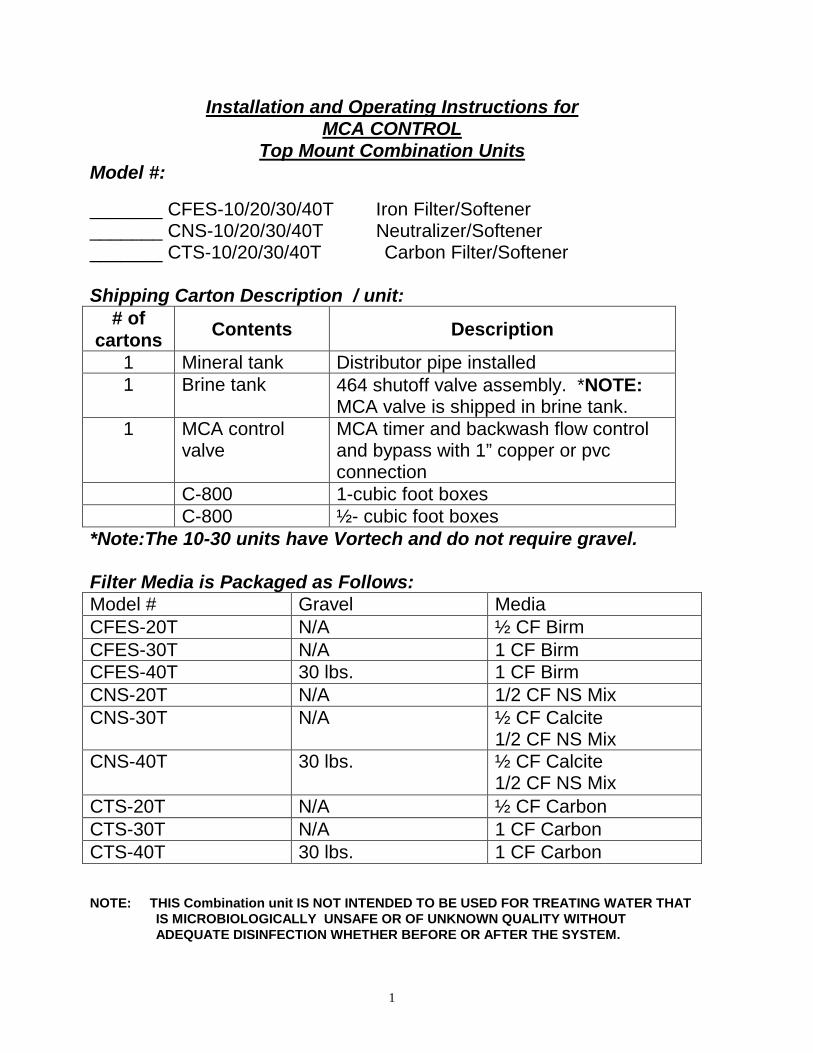
Top Mount Combination Units Model #: _______ CFES-10/20/30/40T Iron Filter/Softener _______ CNS-10/20/30/40T Neutralizer/Softener _______ CTS-10/20/30/40T Carbon Filter/Softener Shipping Carton Description / unit:
# of cartons Contents Description
1 Mineral tank Distributor pipe installed 1 Brine tank 464 shutoff valve assembly. *NOTE:
MCA valve is shipped in brine tank. 1 MCA control
valve MCA timer and backwash flow control and bypass with 1” copper or pvc connection
C-800 1-cubic foot boxes C-800 ½- cubic foot boxes *Note:The 10-30 units have Vortech and do not require gravel. Filter Media is Packaged as Follows: Model # Gravel Media CFES-20T N/A ½ CF Birm CFES-30T N/A 1 CF Birm CFES-40T 30 lbs. 1 CF Birm CNS-20T N/A 1/2 CF NS Mix CNS-30T N/A ½ CF Calcite
1/2 CF NS Mix CNS-40T 30 lbs. ½ CF Calcite
1/2 CF NS Mix CTS-20T N/A ½ CF Carbon CTS-30T N/A 1 CF Carbon CTS-40T 30 lbs. 1 CF Carbon NOTE: THIS Combination unit IS NOT INTENDED TO BE USED FOR TREATING WATER THAT IS MICROBIOLOGICALLY UNSAFE OR OF UNKNOWN QUALITY WITHOUT ADEQUATE DISINFECTION WHETHER BEFORE OR AFTER THE SYSTEM.
2
Water Softener Positioning: 1. Place combination unit in desired position, far enough from walls and
other obstructions to allow for servicing the unit. 2. Place the combination unit within reasonable access to a grounded
115V/60 HZ circuit and a legal drain line connection. Combination Unit Tank Loading: (10/20/30 units have a vortech distributor and do not require gravel) (C-800 is pre-loaded in bottom tank) 1. Remove yellow caplug from top of tank. DO NOT CUT white riser
tube. Tube was prefitted at the factory. 2. Center the distributor and make sure it is resting on the bottom of the
tank. The top of the distributor pipe will be 5/8” above the top of the tank (this was prefitted at the factory).
3. Cover the top opening of the distributor pipe before filling the tank with media.
4. Pour the media provided with the unit into the top of the tank. See page one for your specific model number unit to determine the amount of media to load into the mineral tank.
5. Remove the material used to cover the top opening of the distributor pipe.
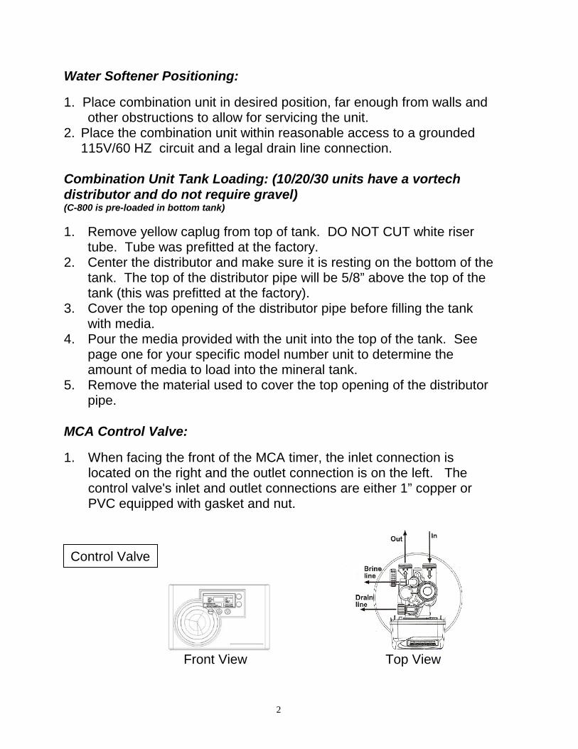
MCA Control Valve: 1. When facing the front of the MCA timer, the inlet connection is
located on the right and the outlet connection is on the left. The control valve's inlet and outlet connections are either 1” copper or PVC equipped with gasket and nut.
Front View Top View
Control Valve
3
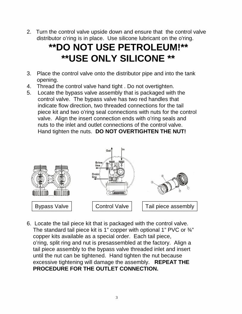
2. Turn the control valve upside down and ensure that the control valve distributor o’ring is in place. Use silicone lubricant on the o'ring.
**DO NOT USE PETROLEUM!** **USE ONLY SILICONE ** 3. Place the control valve onto the distributor pipe and into the tank
opening. 4. Thread the control valve hand tight . Do not overtighten. 5. Locate the bypass valve assembly that is packaged with the control valve. The bypass valve has two red handles that indicate flow direction, two threaded connections for the tail piece kit and two o’ring seal connections with nuts for the control valve. Align the insert connection ends with o’ring seals and nuts to the inlet and outlet connections of the control valve. Hand tighten the nuts. DO NOT OVERTIGHTEN THE NUT!
6. Locate the tail piece kit that is packaged with the control valve. The standard tail piece kit is 1” copper with optional 1” PVC or ¾” copper kits available as a special order. Each tail piece, o’ring, split ring and nut is presassembled at the factory. Align a tail piece assembly to the bypass valve threaded inlet and insert until the nut can be tightened. Hand tighten the nut because excessive tightening will damage the assembly. REPEAT THE PROCEDURE FOR THE OUTLET CONNECTION.
Control Valve Bypass Valve Tail piece assembly
4
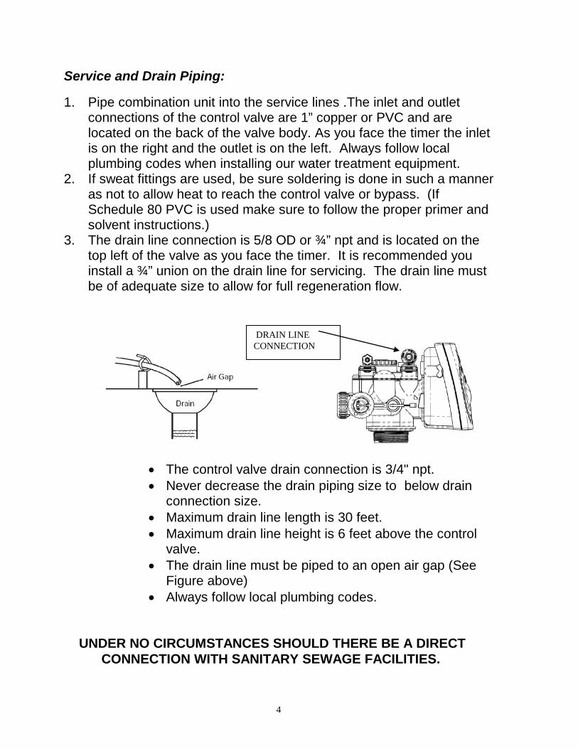
Service and Drain Piping: 1. Pipe combination unit into the service lines .The inlet and outlet
connections of the control valve are 1” copper or PVC and are located on the back of the valve body. As you face the timer the inlet is on the right and the outlet is on the left. Always follow local plumbing codes when installing our water treatment equipment.
2. If sweat fittings are used, be sure soldering is done in such a manner as not to allow heat to reach the control valve or bypass. (If Schedule 80 PVC is used make sure to follow the proper primer and solvent instructions.)
3. The drain line connection is 5/8 OD or ¾” npt and is located on the top left of the valve as you face the timer. It is recommended you install a ¾” union on the drain line for servicing. The drain line must be of adequate size to allow for full regeneration flow.
• The control valve drain connection is 3/4" npt. • Never decrease the drain piping size to below drain
connection size. • Maximum drain line length is 30 feet. • Maximum drain line height is 6 feet above the control
valve. • The drain line must be piped to an open air gap (See
Figure above) • Always follow local plumbing codes.
UNDER NO CIRCUMSTANCES SHOULD THERE BE A DIRECT CONNECTION WITH SANITARY SEWAGE FACILITIES.
DRAIN LINE CONNECTION
5
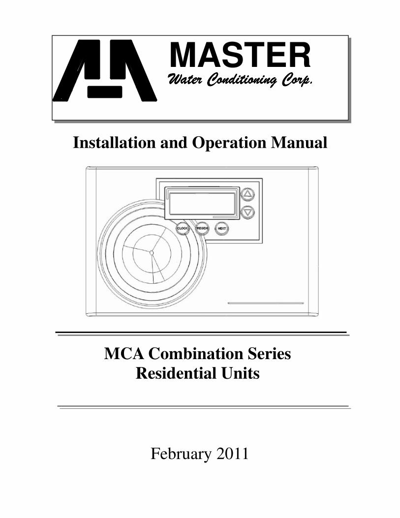
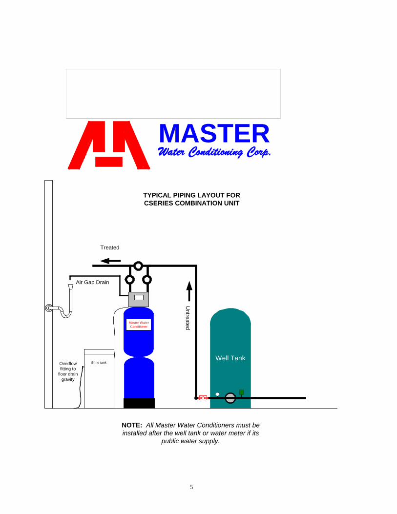
MASTERWater Conditioning Corp.
Well Tank
NOTE: All Master Water Conditioners must beinstalled after the well tank or water meter if its
public water supply.
Brine tank
Air Gap Drain
Overflowfitting to
floor draingravity
Untreated
TYPICAL PIPING LAYOUT FORCSERIES COMBINATION UNIT
Treated
Master WaterConditioner
6
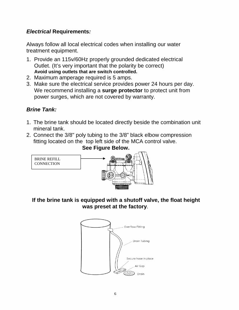
Electrical Requirements: Always follow all local electrical codes when installing our water treatment equipment. 1. Provide an 115v/60Hz properly grounded dedicated electrical Outlet. (It’s very important that the polarity be correct) Avoid using outlets that are switch controlled. 2. Maximum amperage required is 5 amps. 3. Make sure the electrical service provides power 24 hours per day. We recommend installing a surge protector to protect unit from power surges, which are not covered by warranty. Brine Tank: 1. The brine tank should be located directly beside the combination unit
mineral tank. 2. Connect the 3/8" poly tubing to the 3/8” black elbow compression
fitting located on the top left side of the MCA control valve. See Figure Below.
If the brine tank is equipped with a shutoff valve, the float height was preset at the factory.
BRINE REFILL CONNECTION
7
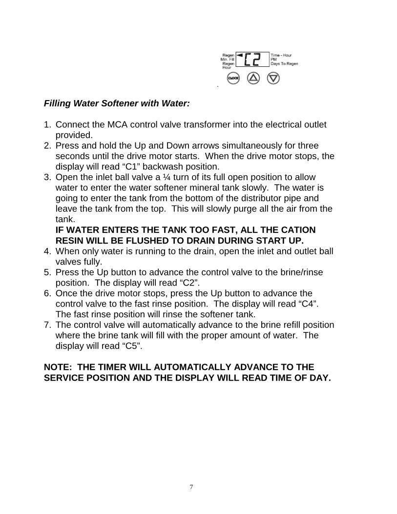
Filling Water Softener with Water: 1. Connect the MCA control valve transformer into the electrical outlet
provided. 2. Press and hold the Up and Down arrows simultaneously for three
seconds until the drive motor starts. When the drive motor stops, the display will read “C1” backwash position.
3. Open the inlet ball valve a ¼ turn of its full open position to allow water to enter the water softener mineral tank slowly. The water is going to enter the tank from the bottom of the distributor pipe and leave the tank from the top. This will slowly purge all the air from the tank. IF WATER ENTERS THE TANK TOO FAST, ALL THE CATION RESIN WILL BE FLUSHED TO DRAIN DURING START UP.
4. When only water is running to the drain, open the inlet and outlet ball valves fully.
5. Press the Up button to advance the control valve to the brine/rinse position. The display will read “C2”.
6. Once the drive motor stops, press the Up button to advance the control valve to the fast rinse position. The display will read “C4”. The fast rinse position will rinse the softener tank.
7. The control valve will automatically advance to the brine refill position where the brine tank will fill with the proper amount of water. The display will read “C5”.
NOTE: THE TIMER WILL AUTOMATICALLY ADVANCE TO THE SERVICE POSITION AND THE DISPLAY WILL READ TIME OF DAY.
8
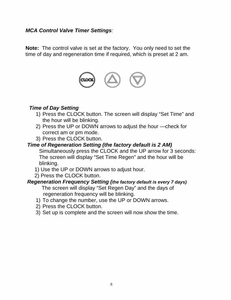
MCA Control Valve Timer Settings: Note: The control valve is set at the factory. You only need to set the time of day and regeneration time if required, which is preset at 2 am.
Time of Day Setting
1) Press the CLOCK button. The screen will display “Set Time” and the hour will be blinking.
2) Press the UP or DOWN arrows to adjust the hour —check for correct am or pm mode.
3) Press the CLOCK button. Time of Regeneration Setting (the factory default is 2 AM)
Simultaneously press the CLOCK and the UP arrow for 3 seconds: The screen will display “Set Time Regen” and the hour will be blinking.
1) Use the UP or DOWN arrows to adjust hour. 2) Press the CLOCK button. Regeneration Frequency Setting (the factory default is every 7 days)
The screen will display “Set Regen Day” and the days of regeneration frequency will be blinking. 1) To change the number, use the UP or DOWN arrows. 2) Press the CLOCK button. 3) Set up is complete and the screen will now show the time.
9
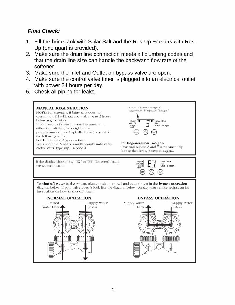
Final Check: 1. Fill the brine tank with Solar Salt and the Res-Up Feeders with Res-
Up (one quart is provided). 2. Make sure the drain line connection meets all plumbing codes and
that the drain line size can handle the backwash flow rate of the softener.
3. Make sure the Inlet and Outlet on bypass valve are open. 4. Make sure the control valve timer is plugged into an electrical outlet
with power 24 hours per day. 5. Check all piping for leaks.
10
11
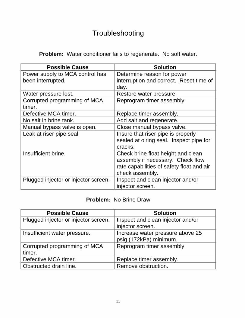
Troubleshooting
Problem: Water conditioner fails to regenerate. No soft water.
Possible Cause Solution Power supply to MCA control has been interrupted.
Determine reason for power interruption and correct. Reset time of day.
Water pressure lost. Restore water pressure. Corrupted programming of MCA timer.
Reprogram timer assembly.
Defective MCA timer. Replace timer assembly. No salt in brine tank. Add salt and regenerate. Manual bypass valve is open. Close manual bypass valve. Leak at riser pipe seal. Insure that riser pipe is properly
sealed at o’ring seal. Inspect pipe for cracks.
Insufficient brine. Check brine float height and clean assembly if necessary. Check flow rate capabilities of safety float and air check assembly.
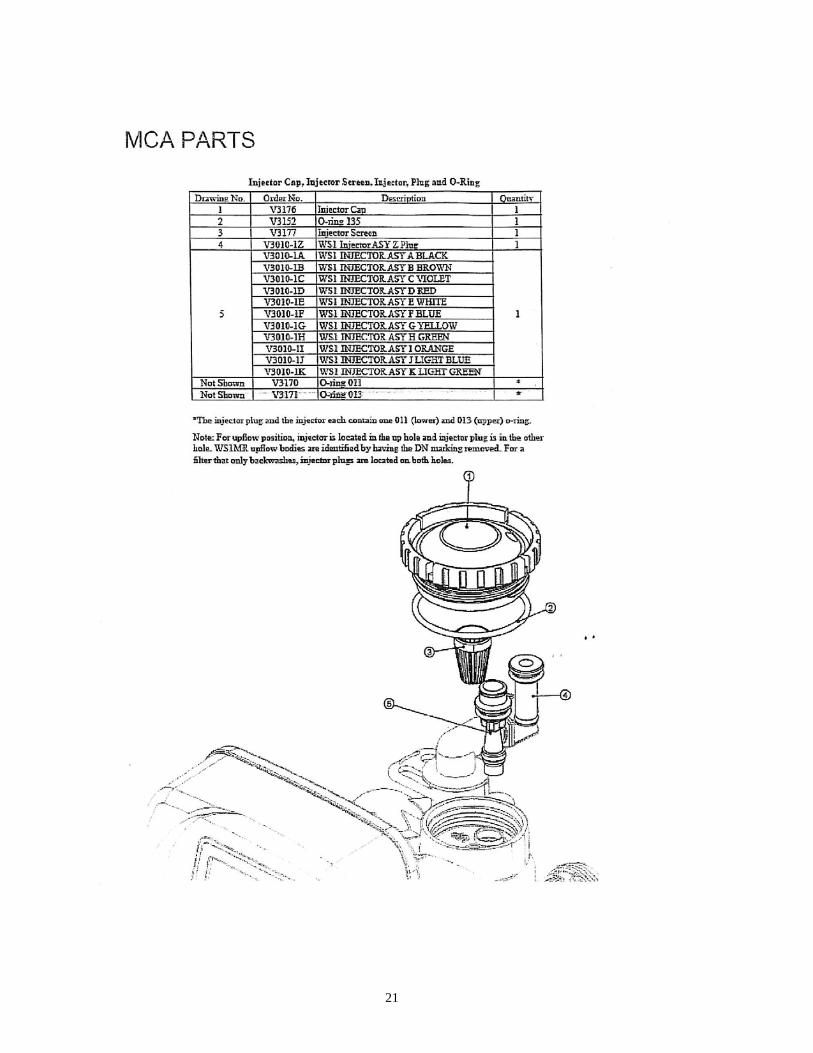
Plugged injector or injector screen. Inspect and clean injector and/or injector screen.
Problem: No Brine Draw
Possible Cause Solution Plugged injector or injector screen. Inspect and clean injector and/or
injector screen. Insufficient water pressure. Increase water pressure above 25
psig (172kPa) minimum. Corrupted programming of MCA timer.
Reprogram timer assembly.
Defective MCA timer. Replace timer assembly. Obstructed drain line. Remove obstruction.
12
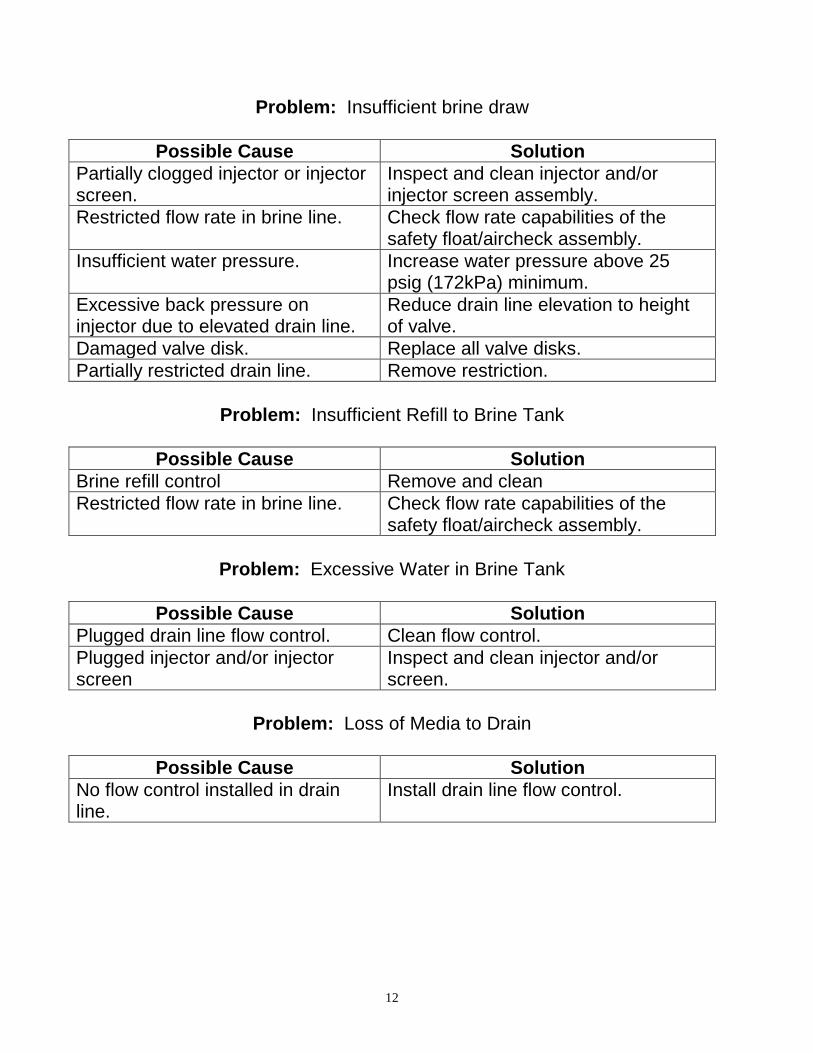
Problem: Insufficient brine draw
Possible Cause Solution Partially clogged injector or injector screen.
Inspect and clean injector and/or injector screen assembly.
Restricted flow rate in brine line. Check flow rate capabilities of the safety float/aircheck assembly.
Insufficient water pressure. Increase water pressure above 25 psig (172kPa) minimum.
Excessive back pressure on injector due to elevated drain line.
Reduce drain line elevation to height of valve.
Damaged valve disk. Replace all valve disks. Partially restricted drain line. Remove restriction.
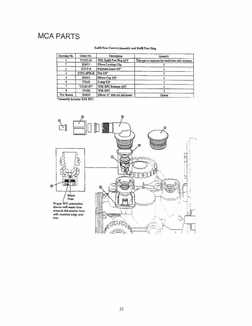
Problem: Insufficient Refill to Brine Tank
Possible Cause Solution
Brine refill control Remove and clean Restricted flow rate in brine line. Check flow rate capabilities of the
safety float/aircheck assembly.
Problem: Excessive Water in Brine Tank
Possible Cause Solution Plugged drain line flow control. Clean flow control. Plugged injector and/or injector screen
Inspect and clean injector and/or screen.
Problem: Loss of Media to Drain
Possible Cause Solution No flow control installed in drain line.
Install drain line flow control.
13
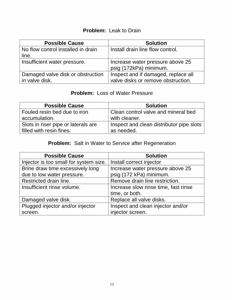
Problem: Leak to Drain
Possible Cause Solution No flow control installed in drain line.
Install drain line flow control.
Insufficient water pressure. Increase water pressure above 25 psig (172kPa) minimum.
Damaged valve disk or obstruction in valve disk.
Inspect and if damaged, replace all valve disks or remove obstruction.
Problem: Loss of Water Pressure
Possible Cause Solution Fouled resin bed due to iron accumulation.
Clean control valve and mineral bed with cleaner.
Slots in riser pipe or laterals are filled with resin fines.
Inspect and clean distributor pipe slots as needed.
Problem: Salt in Water to Service after Regeneration
Possible Cause Solution Injector is too small for system size. Install correct injector Brine draw time excessively long due to low water pressure.
Increase water pressure above 25 psig (172 kPa) minimum.
Restricted drain line. Remove drain line restriction. Insufficient rinse volume. Increase slow rinse time, fast rinse
time, or both. Damaged valve disk. Replace all valve disks. Plugged injector and/or injector screen.
Inspect and clean injector and/or injector screen.
14
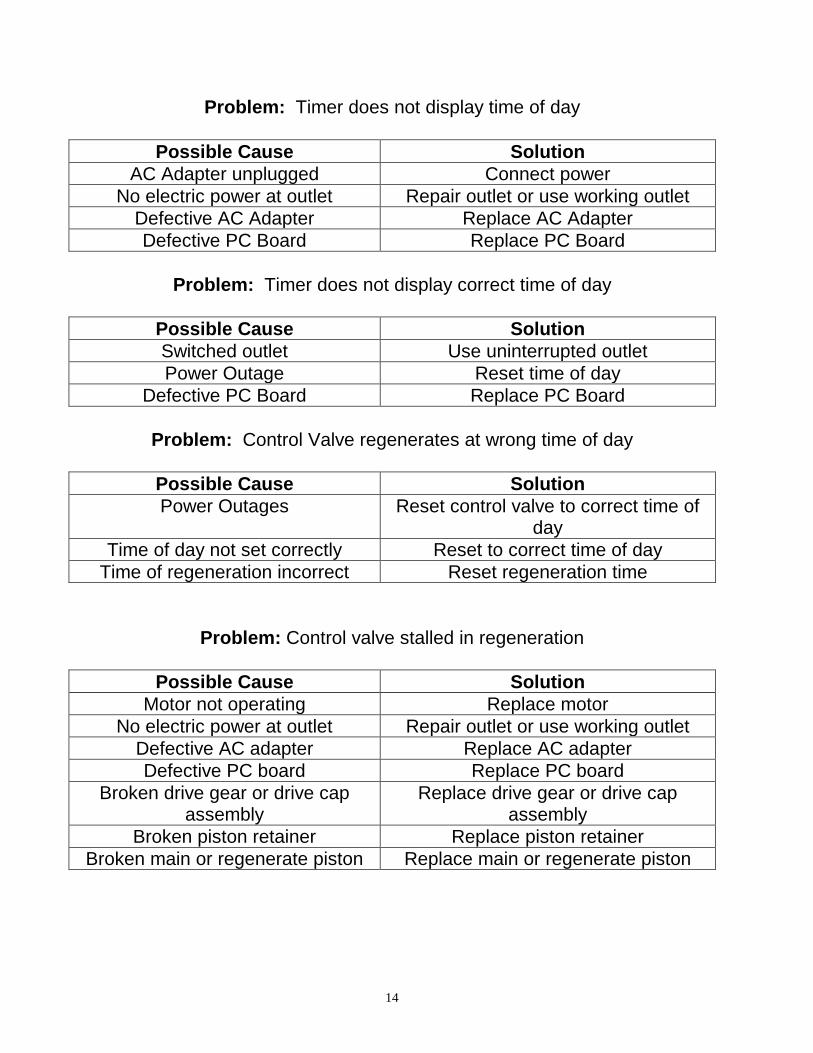
Problem: Timer does not display time of day
Possible Cause Solution AC Adapter unplugged Connect power
No electric power at outlet Repair outlet or use working outlet Defective AC Adapter Replace AC Adapter Defective PC Board Replace PC Board
Problem: Timer does not display correct time of day
Possible Cause Solution Switched outlet Use uninterrupted outlet Power Outage Reset time of day
Defective PC Board Replace PC Board
Problem: Control Valve regenerates at wrong time of day
Possible Cause Solution Power Outages Reset control valve to correct time of
day Time of day not set correctly Reset to correct time of day
Time of regeneration incorrect Reset regeneration time
Problem: Control valve stalled in regeneration
Possible Cause Solution Motor not operating Replace motor
No electric power at outlet Repair outlet or use working outlet Defective AC adapter Replace AC adapter Defective PC board Replace PC board
Broken drive gear or drive cap assembly
Replace drive gear or drive cap assembly
Broken piston retainer Replace piston retainer Broken main or regenerate piston Replace main or regenerate piston
15
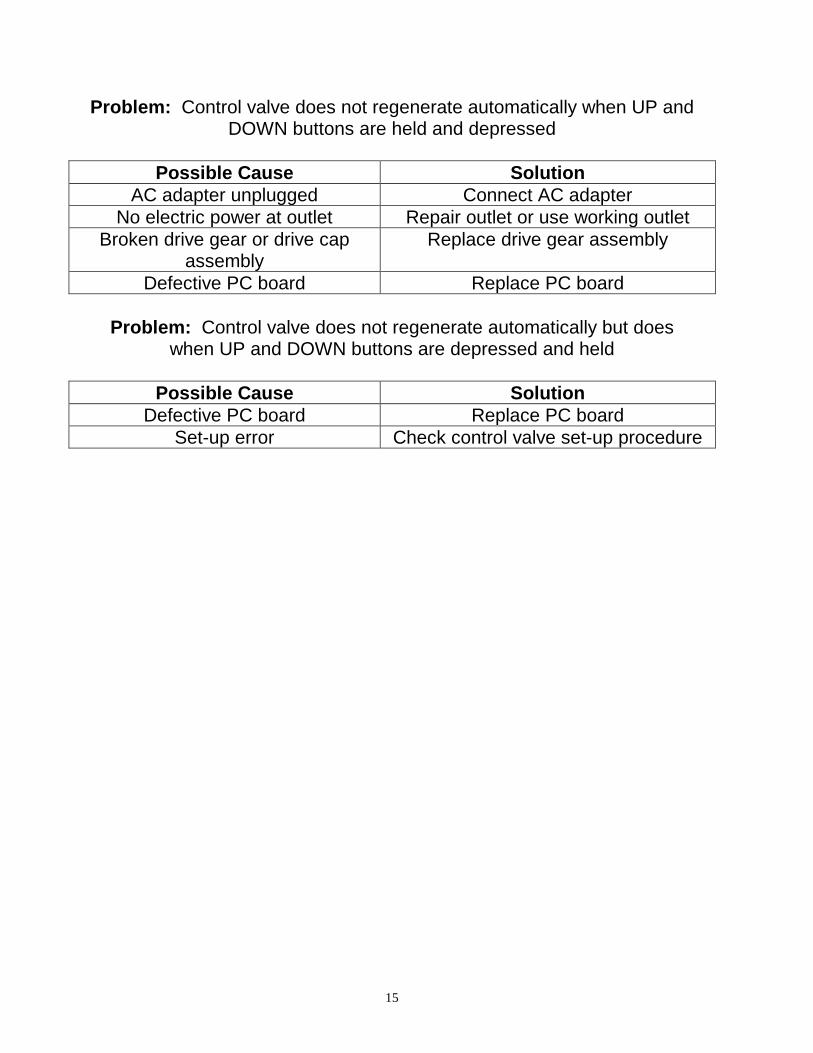
Problem: Control valve does not regenerate automatically when UP and DOWN buttons are held and depressed
Possible Cause Solution
AC adapter unplugged Connect AC adapter No electric power at outlet Repair outlet or use working outlet
Broken drive gear or drive cap assembly
Replace drive gear assembly
Defective PC board Replace PC board
Problem: Control valve does not regenerate automatically but does when UP and DOWN buttons are depressed and held
Possible Cause Solution
Defective PC board Replace PC board Set-up error Check control valve set-up procedure
16
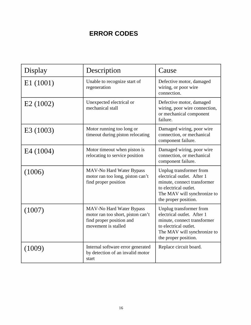
ERROR CODES
Display Description Cause
E1 (1001) Unable to recognize start of regeneration
Defective motor, damaged wiring, or poor wire connection.
E2 (1002) Unexpected electrical or mechanical stall
Defective motor, damaged wiring, poor wire connection, or mechanical component failure.
E3 (1003) Motor running too long or timeout during piston relocating
Damaged wiring, poor wire connection, or mechanical component failure.
E4 (1004) Motor timeout when piston is relocating to service position
Damaged wiring, poor wire connection, or mechanical component failure.
(1006) MAV-No Hard Water Bypass motor ran too long, piston can’t find proper position
Unplug transformer from electrical outlet. After 1 minute, connect transformer to electrical outlet. The MAV will synchronize to the proper position.
(1007) MAV-No Hard Water Bypass motor ran too short, piston can’t find proper position and movement is stalled
Unplug transformer from electrical outlet. After 1 minute, connect transformer to electrical outlet. The MAV will synchronize to the proper position.
(1009) Internal software error generated by detection of an invalid motor start
Replace circuit board.

17
18
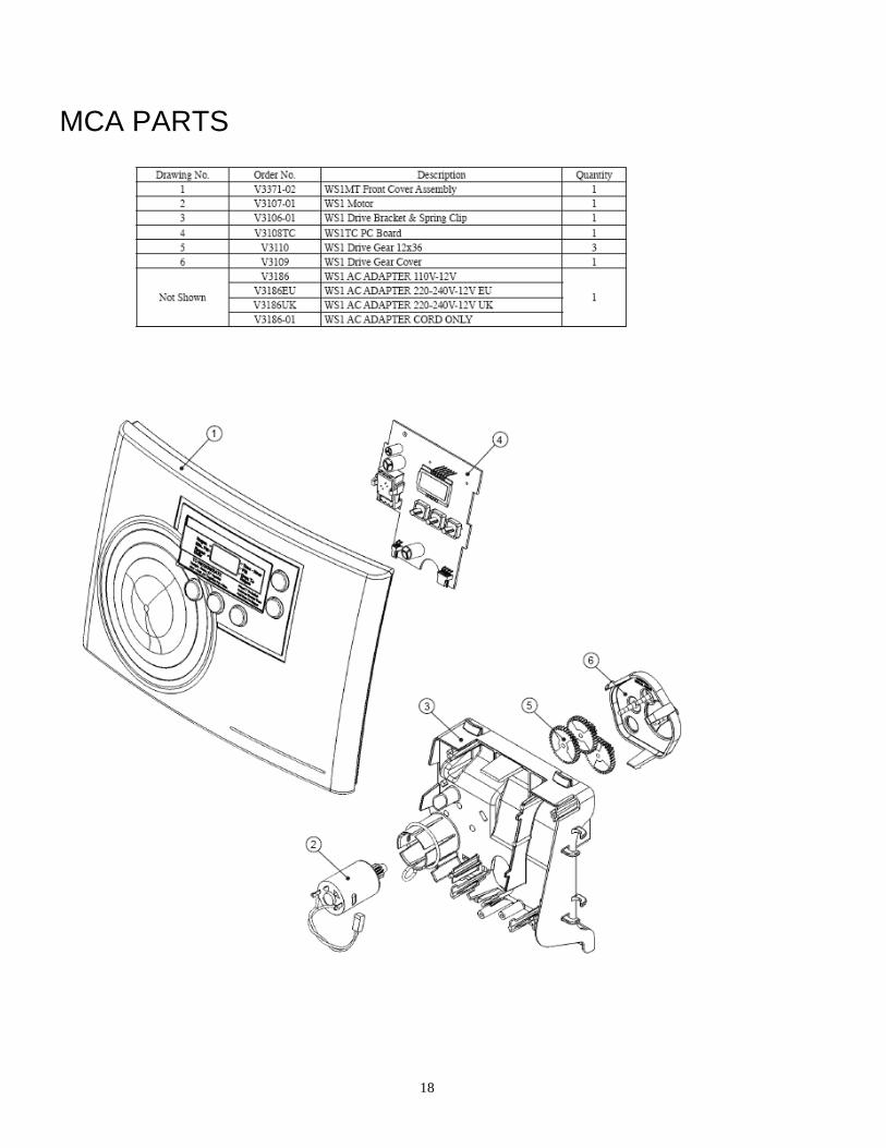
MCA PARTS
19
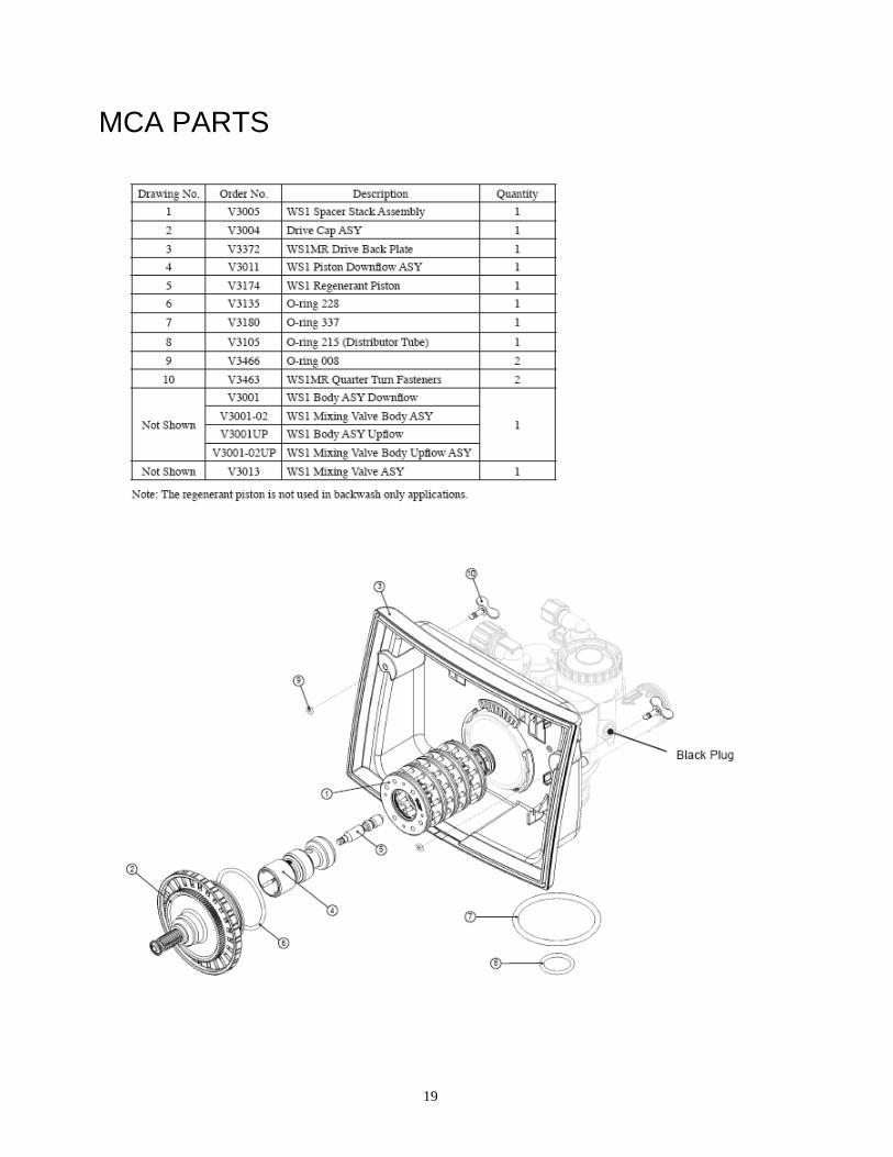
MCA PARTS
20
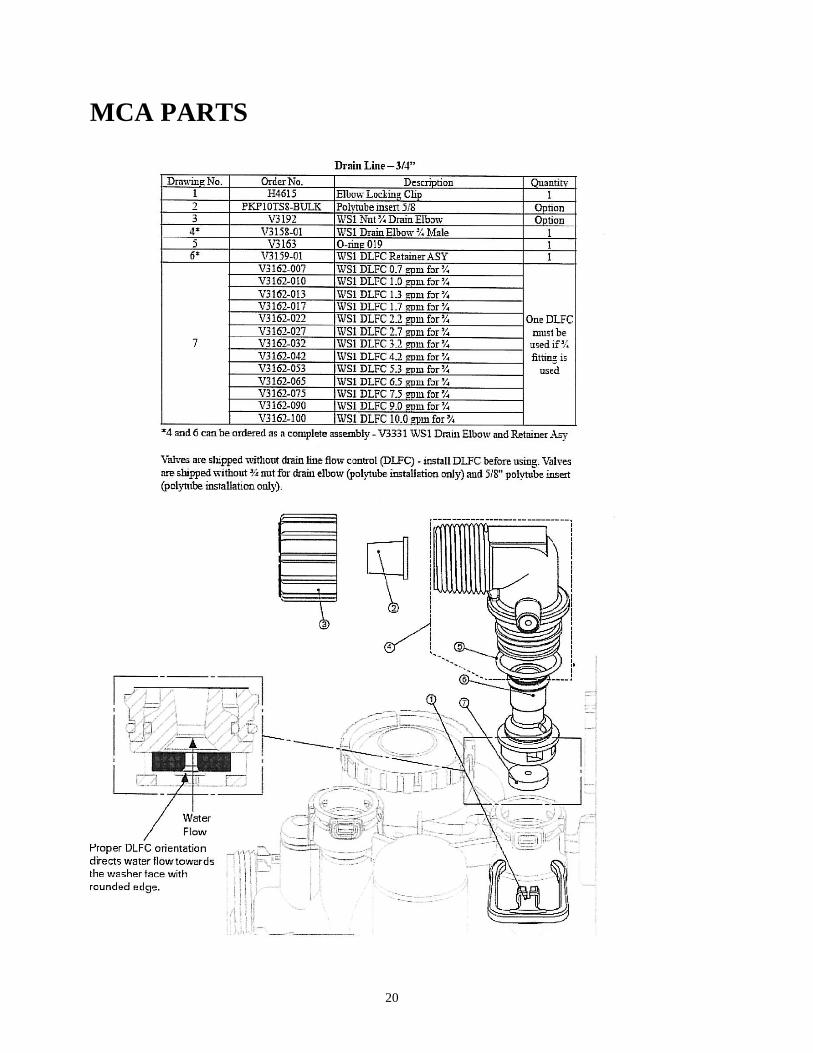
MCA PARTS
21
22
12 YEAR LIMITED WARRANTY As of Oct. 1, 1995
This Residential Water Conditioner is warranted for a period of one year from date of
purchase by first user against defects in materials and workmanship. In addition, the complete
control valve is warranted for five years. The control valve body (excluding internals and electrical
parts) is warranted for six years. The mineral tank, plastic brine tank or cabinet tank (excluding
mineral) is warranted against rust, corrosion or bursting for a period of twelve years from date of
manufacture. Except, as specifically set forth in this paragraph, Master Water Conditioning
Corporation makes no other warranties, express or implied.
This warranty shall be void if the conditioner is moved from the place of original installation,
or if damage is caused by misuse, misapplication, accident, freezing, flood, fire or if not installed in
accordance with instructions furnished by Master Water Conditioning Corporation.
This warranty shall be void in the event of damages from external sources or where the
conditioner has been operated at pressure in excess of 100 pounds per square inch or at a temperature
greater than 100 degrees F. or less than 32 degrees F. Incidental costs or consequential damages are
not covered by this warranty.
All defective parts shall be returned prepaid to Master Water Conditioning Corporation for
inspection. Master shall not be liable for labor charges other than Master factory repairs.
This warranty gives you specific legal rights, and you may have other rights which vary from
state to state. Some states do not allow limitations on duration of implied warranties or exclusion of
incidental or consequential damages, so the above limitations may not apply to you.
All claims must be submitted in writing to Master Water Conditioning Corporation at 224
Shoemaker Road, Pottstown, Pennsylvania 19464 within thirty (30) days from the discovery of the
defect. Master Water Conditioning Corporation thereafter will correct defective parts and
workmanship or rusting, corrosion or bursting within sixty (60) days.
Failure to notify Master by completing, signing and returning the registration card within
twenty (20) days of the purchase shall void the warranty.
224 Shoemaker Rd. Pottstown, Pa. 19464
MASTERWater Conditioning Corp.