Embed Size (px)
Citation preview
© 2
004,
200
5, K
evin
Ska
dron
A Quick Thermal Tutorial
Kevin SkadronMircea Stan
Univ. of VirginiaHotSpot group
2
© 2
004,
200
5, K
evin
Ska
dron
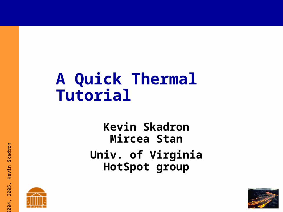
Cooking-aware computing
Some chips rated for 100°C+
3
© 2
004,
200
5, K
evin
Ska
dron
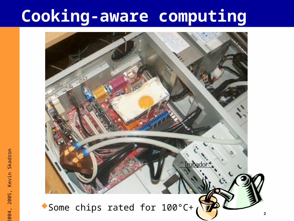
Overview
1. What is thermal?
2. Why thermal?
3. Why should architects care?
4. Useful thermal background5. Dynamic thermal mgmt. (DTM)
- Prelim CMP, SMT, and GPU results
6. Thermal Modeling- Including some illustrative HotSpot
details
7. Sensor issues
8. Some research questions
4
© 2
004,
200
5, K
evin
Ska
dron
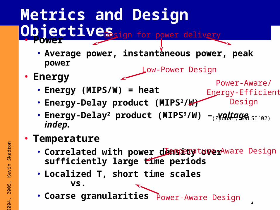
Metrics and Design Objectives
• Power• Average power, instantaneous power, peak power
• Energy• Energy (MIPS/W) = heat
• Energy-Delay product (MIPS2/W)
• Energy-Delay2 product (MIPS3/W) – voltage indep.
• Temperature• Correlated with power density over sufficiently
large time periods
• Localized T, short time scalesvs.
• Coarse granularities
(Zyuban, GVLSI’02)
Low-Power Design
Power-Aware/Energy-Efficient
Design
Temperature-Aware Design
Design for power delivery
Power-Aware Design

5
© 2
004,
200
5, K
evin
Ska
dron
Power Dissipation
Processor Alpha 21364
AMD Opteron
HP-PA8700
IBM-Power 4
Intel Itanium 2
Intel Xeon
MIPS R14000
Clock Rate
1.15 GHz 2.2 GHz 870 MHz 1.7 GHz 1.5 GHz 3.2 GHz 600 MHz
Power (Max)
110W 86 W 75W 100W 130W 86W 16W
Source: Microprocessor Report
6
© 2
004,
200
5, K
evin
Ska
dron
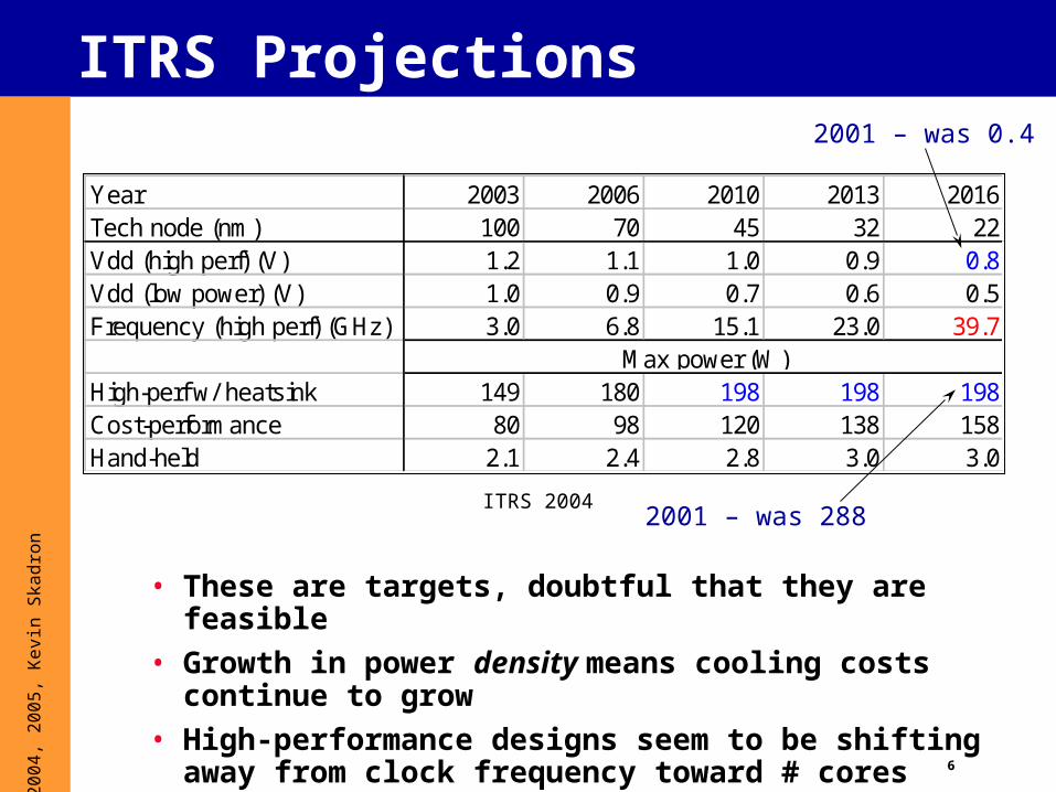
ITRS Projections
• These are targets, doubtful that they are feasible
• Growth in power density means cooling costs continue to grow
• High-performance designs seem to be shifting away from clock frequency toward # cores
ITRS 2004
Year 2003 2006 2010 2013 2016Tech node (nm) 100 70 45 32 22Vdd (high perf) (V) 1.2 1.1 1.0 0.9 0.8Vdd (low power) (V) 1.0 0.9 0.7 0.6 0.5Frequency (high perf) (GHz) 3.0 6.8 15.1 23.0 39.7
High-perf w/ heatsink 149 180 198 198 198Cost-performance 80 98 120 138 158Hand-held 2.1 2.4 2.8 3.0 3.0
Max power (W)
2001 – was 0.4
2001 – was 288
7
© 2
004,
200
5, K
evin
Ska
dron
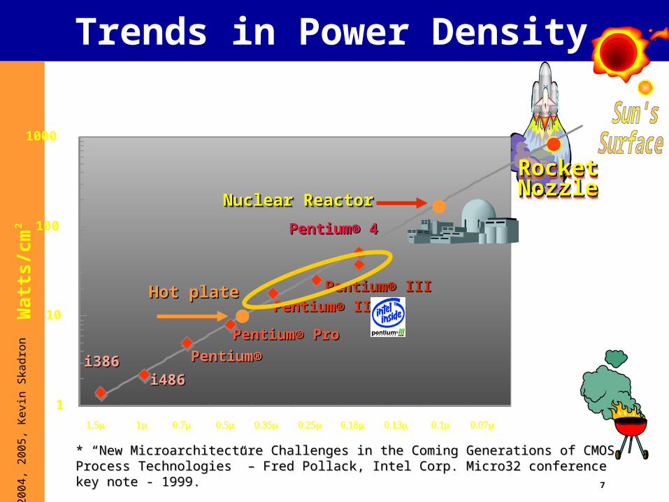
Trends in Power DensityW
att
s/c
m2
1
10
100
1000
i386i386i486i486
Pentium® Pentium®
Pentium® ProPentium® Pro
Pentium® IIPentium® IIPentium® IIIPentium® IIIHot plateHot plate
Nuclear ReactorNuclear ReactorNuclear ReactorNuclear Reactor
RocketRocketNozzleNozzleRocketRocketNozzleNozzle
* “New Microarchitecture Challenges in the Coming Generations of CMOS Process Technologies” – * “New Microarchitecture Challenges in the Coming Generations of CMOS Process Technologies” – Fred Pollack, Intel Corp. Micro32 conference key note - 1999.Fred Pollack, Intel Corp. Micro32 conference key note - 1999.
Pentium® 4Pentium® 4
8
© 2
004,
200
5, K
evin
Ska
dron
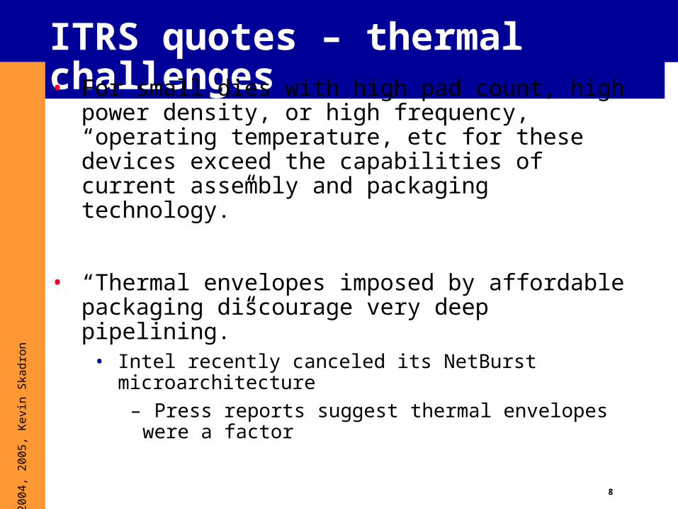
ITRS quotes – thermal challenges• For small dies with high pad count, high power
density, or high frequency, “operating temperature, etc for these devices exceed the capabilities of current assembly and packaging technology.”
• “Thermal envelopes imposed by affordable packaging discourage very deep pipelining.”
• Intel recently canceled its NetBurst microarchitecture
– Press reports suggest thermal envelopes were a factor
9
© 2
004,
200
5, K
evin
Ska
dron
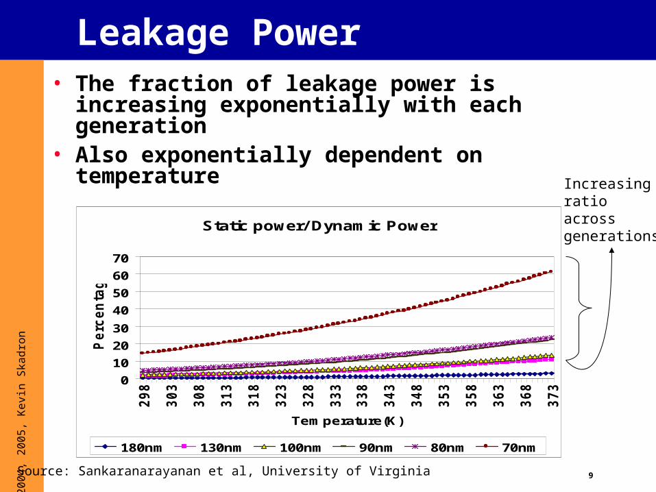
Leakage Power• The fraction of leakage power is increasing
exponentially with each generation• Also exponentially dependent on temperature
Static power/ Dynamic Power
0
10
20
30
40
50
60
70
298
303
308
313
318
323
328
333
338
343
348
353
358
363
368
373
Temperature(K)
Pe
rcen
tag
e
180nm 130nm 100nm 90nm 80nm 70nm
Increasingratioacrossgenerations
Source: Sankaranarayanan et al, University of Virginia
10
© 2
004,
200
5, K
evin
Ska
dron
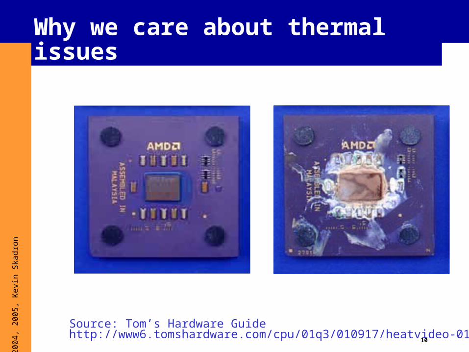
Why we care about thermal issues
Source: Tom’s Hardware Guidehttp://www6.tomshardware.com/cpu/01q3/010917/heatvideo-01.html

11
© 2
004,
200
5, K
evin
Ska
dron
Other Costs of High Heat Flux
• Packaging, cooling costs
• Noise (quiet high-speed fans are expensive)
• Form factors
• Some chips may already be underclocked due to thermal constraints!
• (especially mobile and sealed systems)
• Temperature-dependent phenomena• Leakage
• IR voltage drop (R is T-dep)
• Aging (e.g. EM)
• Performance (carrier mobility)

12
© 2
004,
200
5, K
evin
Ska
dron
Packaging cost
From Cray (local power generator and refrigeration)…
Source: Gordon Bell, “A Seymour Cray perspective”http://www.research.microsoft.com/users/gbell/craytalk/
13
© 2
004,
200
5, K
evin
Ska
dron
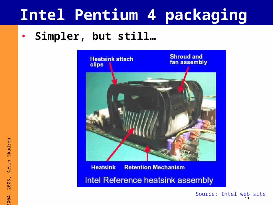
Intel Pentium 4 packaging• Simpler, but still…
Source: Intel web site
14
© 2
004,
200
5, K
evin
Ska
dron
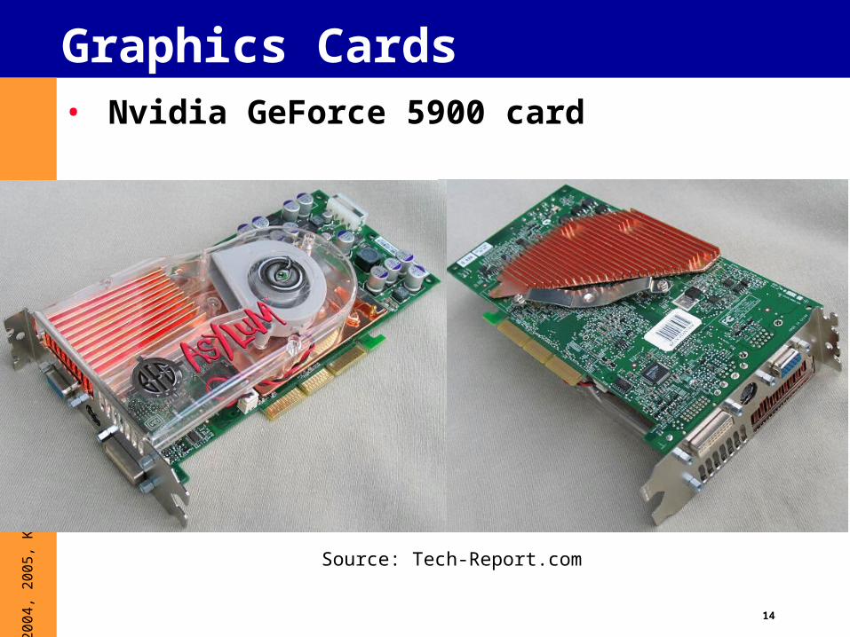
Graphics Cards• Nvidia GeForce 5900 card
Source: Tech-Report.com
15
© 2
004,
200
5, K
evin
Ska
dron
Apple G5 – liquid cooling• Don’t know details
• In G5 case, liquid is probably for noise
• Lots of people in thermal engineering community think liquid is inevitable, especially for server rooms
• But others say no:• This introduces a whole new kind of leakage
problem
• Water and electronics don’t mix!
16
© 2
004,
200
5, K
evin
Ska
dron
Environment• Equivalent power (with only 30% efficiency) for AC
• CFCs used for refrigeration

17
© 2
004,
200
5, K
evin
Ska
dron
Overview
1. What is thermal?
2. Why thermal?
3. Why should architects care?
4. Useful thermal background5. Dynamic thermal mgmt. (DTM)
- Prelim CMP, SMT, and GPU results
6. Thermal Modeling
7. Sensor issues
8. Some research questions

18
© 2
004,
200
5, K
evin
Ska
dron
Worst-Case leads to Over-design• Average case temperature lower than worst-case
• Aggressive clock gating
• Application variations
• Underutilized resources, e.g. FP units during integer code
• Currently 20-40% difference
Source: Gunther et al, ITJ 2001
Reduced targetpower density
Reduced coolingcost
TDP
19
© 2
004,
200
5, K
evin
Ska
dron
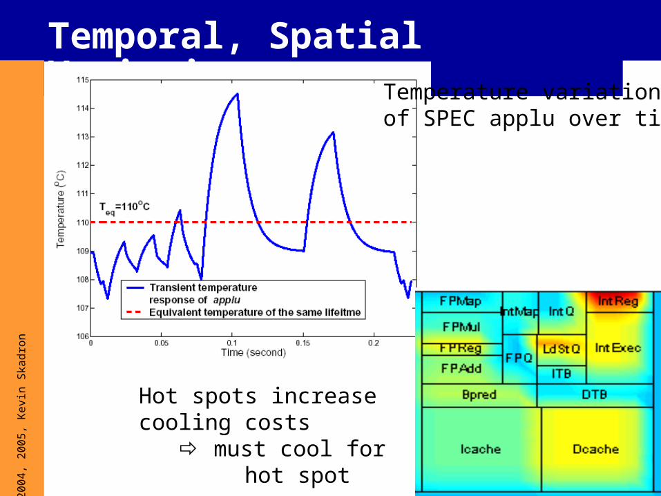
Temporal, Spatial VariationsTemperature variationof SPEC applu over time
Hot spots increase cooling costs must cool for hot spot
20
© 2
004,
200
5, K
evin
Ska
dron
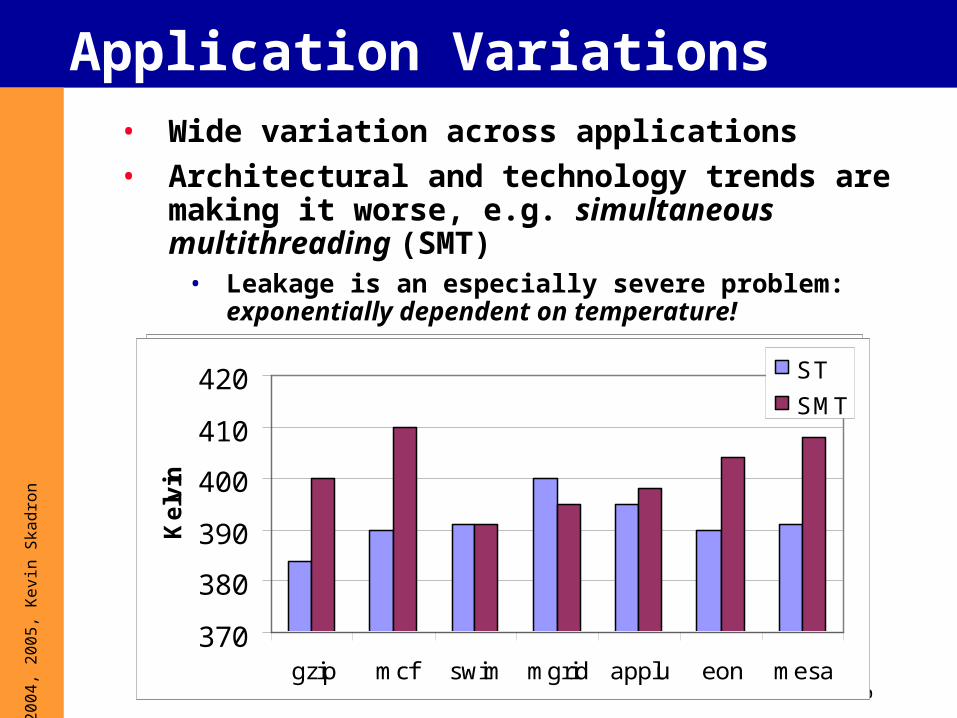
Application Variations• Wide variation across applications
• Architectural and technology trends are making it worse, e.g. simultaneous multithreading (SMT)
• Leakage is an especially severe problem: exponentially dependent on temperature!
370
380
390
400
410
420
gzip mcf swim mgrid applu eon mesa
Ke
lvin
370
380
390
400
410
420
gzip mcf swim mgrid applu eon mesa
Ke
lvin
ST
SMT

21
© 2
004,
200
5, K
evin
Ska
dron
Heat vs. Temperature• Different time, space scales
• Heat: no notion of spatial locality
Temperature-aware computing:
Optimize performance subject to a temperature constraint
22
© 2
004,
200
5, K
evin
Ska
dron
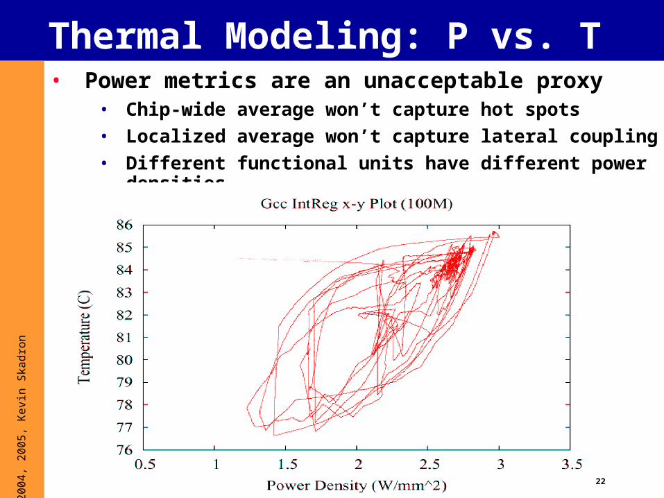
Thermal Modeling: P vs. T• Power metrics are an unacceptable proxy
• Chip-wide average won’t capture hot spots
• Localized average won’t capture lateral coupling
• Different functional units have different power densities

23
© 2
004,
200
5, K
evin
Ska
dron
Overview
1. What is thermal?
2. Why thermal?
3. Why should architects care?
4. Useful thermal background5. Dynamic thermal mgmt. (DTM)
- Prelim CMP, SMT, and GPU results
6. Thermal Modeling
7. Sensor issues
8. Some research questions
24
© 2
004,
200
5, K
evin
Ska
dron
Thermal consequencesTemperature affects:
• Circuit performance
• Circuit power (leakage)
• IC reliability
• IC and system packaging cost
• Environment
25
© 2
004,
200
5, K
evin
Ska
dron
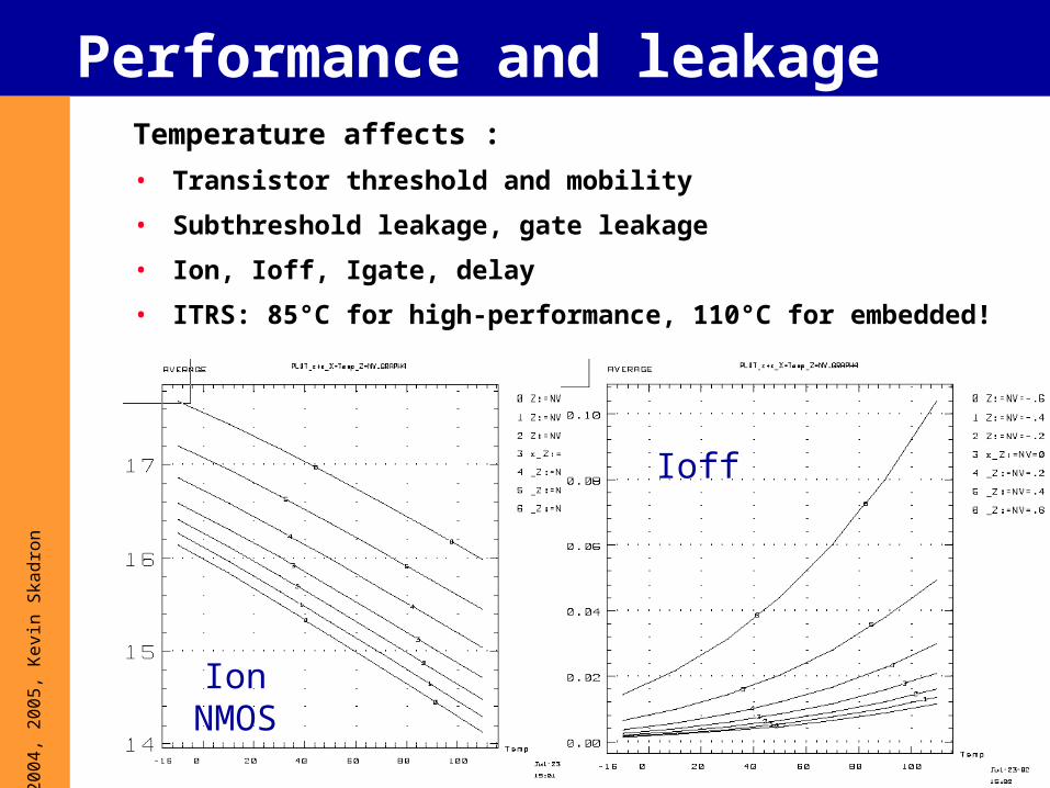
Performance and leakageTemperature affects :
• Transistor threshold and mobility
• Subthreshold leakage, gate leakage
• Ion, Ioff, Igate, delay
• ITRS: 85°C for high-performance, 110°C for embedded!
IonNMOS
Ioff
26
© 2
004,
200
5, K
evin
Ska
dron
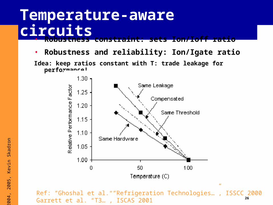
Temperature-aware circuits
• Robustness constraint: sets Ion/Ioff ratio
• Robustness and reliability: Ion/Igate ratio
Idea: keep ratios constant with T: trade leakage for performance!
Ref: “Ghoshal et al. “Refrigeration Technologies…”, ISSCC 2000Garrett et al. “T3…”, ISCAS 2001
27
© 2
004,
200
5, K
evin
Ska
dron
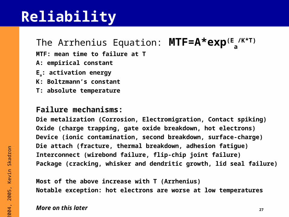
Reliability
The Arrhenius Equation: MTF=A*exp(Ea
/K*T) MTF: mean time to failure at T
A: empirical constant
Ea: activation energy
K: Boltzmann’s constant
T: absolute temperature
Failure mechanisms:Die metalization (Corrosion, Electromigration, Contact spiking)
Oxide (charge trapping, gate oxide breakdown, hot electrons)
Device (ionic contamination, second breakdown, surface-charge)
Die attach (fracture, thermal breakdown, adhesion fatigue)
Interconnect (wirebond failure, flip-chip joint failure)
Package (cracking, whisker and dendritic growth, lid seal failure)
Most of the above increase with T (Arrhenius)
Notable exception: hot electrons are worse at low temperatures
28
© 2
004,
200
5, K
evin
Ska
dron
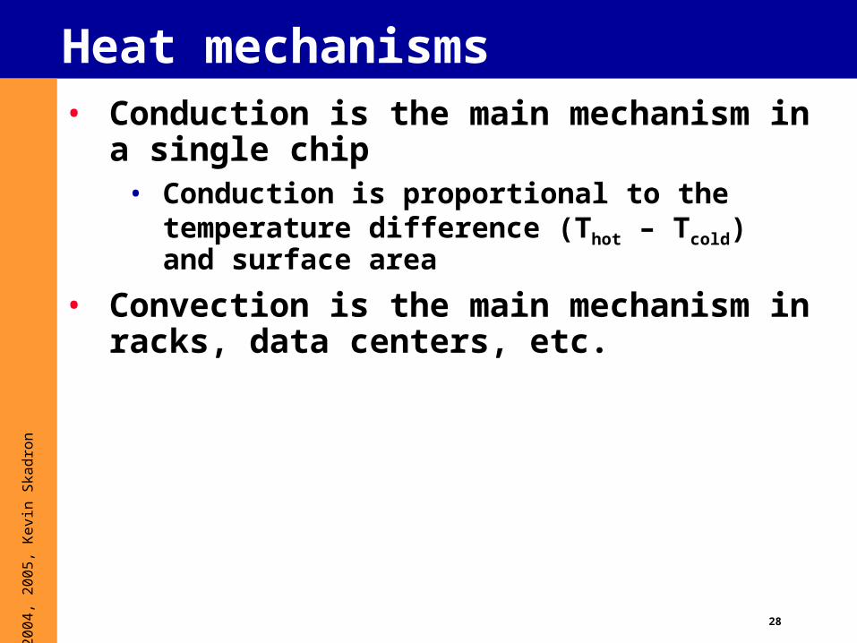
Heat mechanisms• Conduction is the main mechanism in a
single chip• Conduction is proportional to the temperature
difference (Thot – Tcold) and surface area
• Convection is the main mechanism in racks, data centers, etc.
29
© 2
004,
200
5, K
evin
Ska
dron
Carnot Efficiency
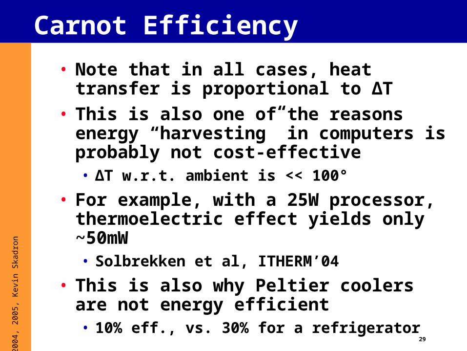
• Note that in all cases, heat transfer is proportional to ΔT
• This is also one of the reasons energy “harvesting” in computers is probably not cost-effective• ΔT w.r.t. ambient is << 100°
• For example, with a 25W processor, thermoelectric effect yields only ~50mW• Solbrekken et al, ITHERM’04
• This is also why Peltier coolers are not energy efficient• 10% eff., vs. 30% for a refrigerator

30
© 2
004,
200
5, K
evin
Ska
dron
Surface-to-surface contacts• Not negligible, heat crowding
• Thermal greases/epoxy (can “pump-out”)
• Phase Change Films (undergo a transition from solid to semi-solid with the application of heat)
Source: CRC Press, R. Remsburg Ed. “Thermal Design of Electronic Equipment”, 2001
31
© 2
004,
200
5, K
evin
Ska
dron
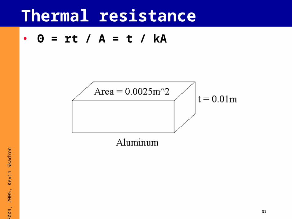
Thermal resistance• Θ = rt / A = t / kA
32
© 2
004,
200
5, K
evin
Ska
dron
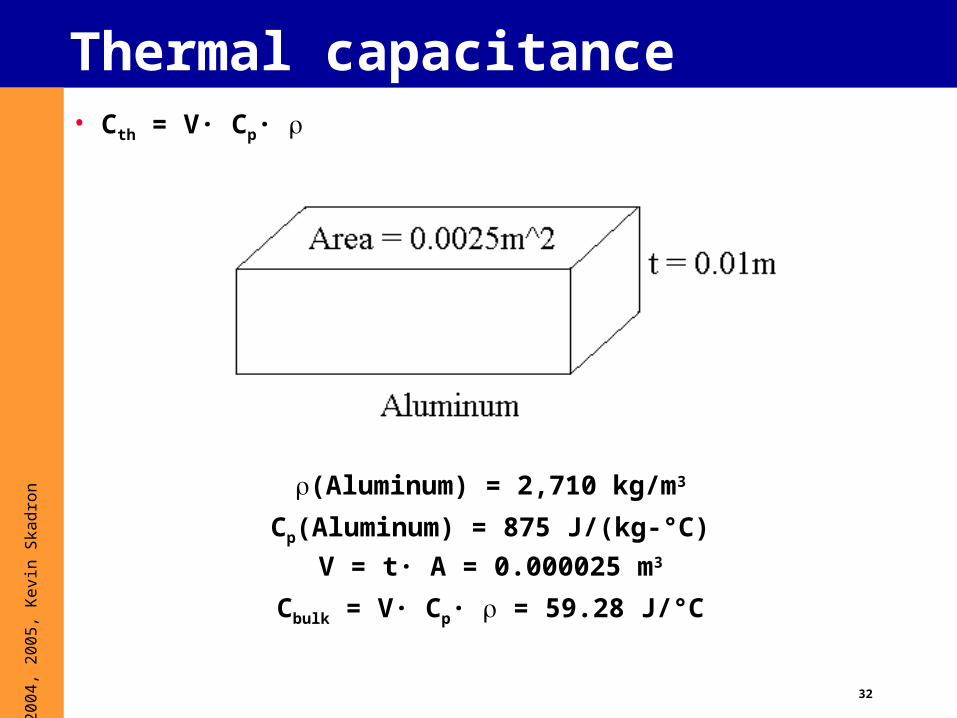
Thermal capacitance• Cth = V· Cp·
(Aluminum) = 2,710 kg/m3
Cp(Aluminum) = 875 J/(kg-°C)
V = t· A = 0.000025 m3
Cbulk = V· Cp· = 59.28 J/°C

33
© 2
004,
200
5, K
evin
Ska
dron
Simplistic steady-state model
All thermal transfer: R = k/A
Power density matters!Ohm’s law for thermals
(steady-state)
V = I · R -> T = P · R
T_hot = P · Rth + T_amb
Ways to reduce T_hot:
- reduce P (power-aware)
- reduce Rth (packaging, spread heat)
- reduce T_amb (Alaska?)
- maybe also take advantage of transients (Cth)
T_hot
T_amb

34
© 2
004,
200
5, K
evin
Ska
dron
Simplistic dynamic thermal model
Electrical-thermal duality
V temp (T)
I power (P)
R thermal resistance (Rth)
C thermal capacitance (Cth)
RC time constant
KCL
differential eq. I = C · dV/dt + V/R
difference eq. V = I/C · t + V/RC · t
thermal domain T = P/C · t + T/RC · t
(T = T_hot – T_amb)
One can compute stepwise changes in temperature for any granularity at which one can get P, T, R, C
T_hot
T_amb
35
© 2
004,
200
5, K
evin
Ska
dron
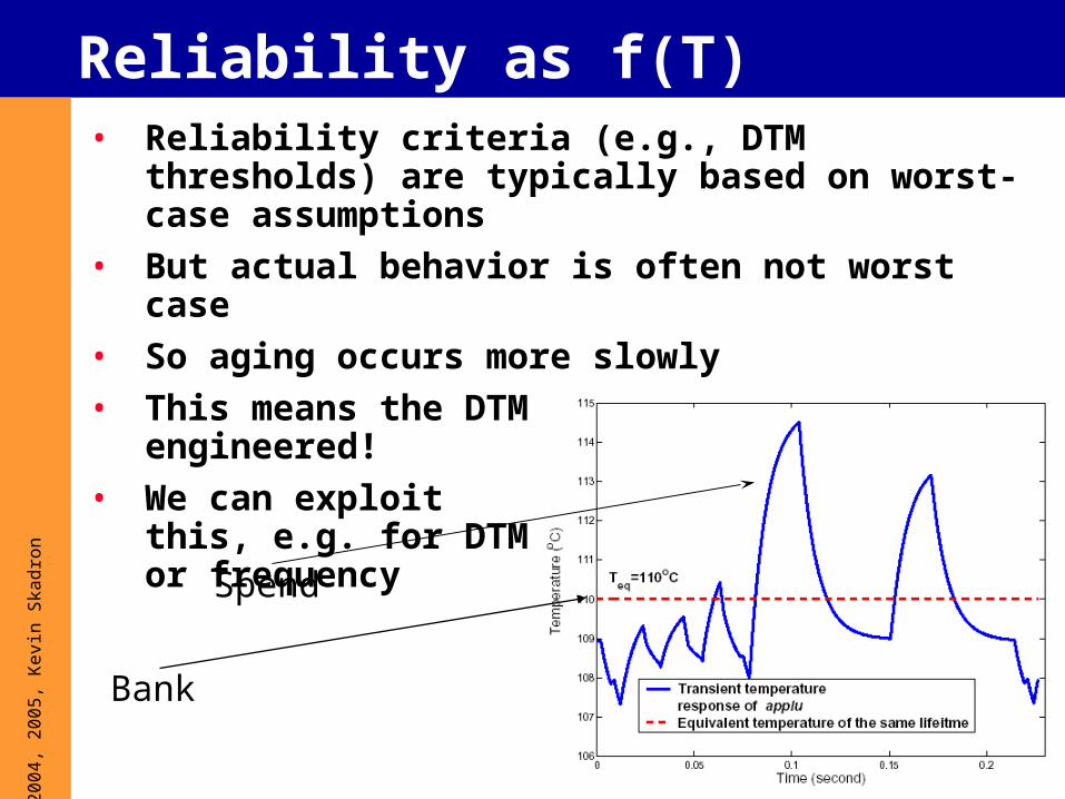
Reliability as f(T)• Reliability criteria (e.g., DTM thresholds) are typically
based on worst-case assumptions
• But actual behavior is often not worst case
• So aging occurs more slowly
• This means the DTM design is over-engineered!
• We can exploit this, e.g. for DTM or frequency
Bank
Spend
36
© 2
004,
200
5, K
evin
Ska
dron
EM Model
( )
0
1,
( )
failure at E
kT tth the dt const
kT t
( )1( )
( )
aE
kT tR t ekT t
Life Consumption
Rate:
Apply in a “lumped” fashion at the granularity of microarchitecture units, just like RAMP [Srinivasan et al.]
37
© 2
004,
200
5, K
evin
Ska
dron
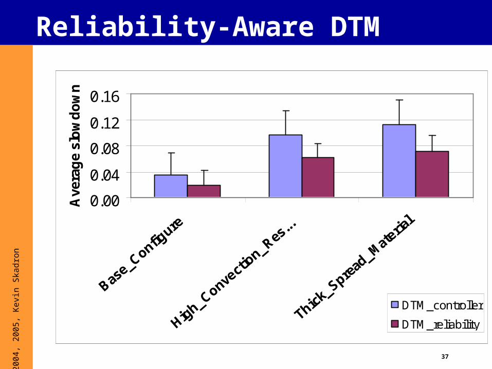
Reliability-Aware DTM
0.00
0.04
0.08
0.12
0.16
Base_C
onfigure
High_Conve
ctio
n_Res...
Thick_
Spread
_Materia
l
Ave
rag
e sl
ow
do
wn
DTM_controller
DTM_reliability
38
© 2
004,
200
5, K
evin
Ska
dron
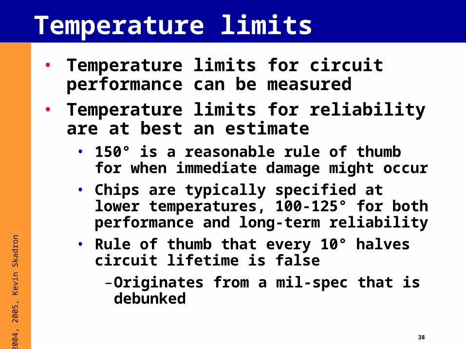
Temperature limits
• Temperature limits for circuit performance can be measured
• Temperature limits for reliability are at best an estimate
• 150° is a reasonable rule of thumb for when immediate damage might occur
• Chips are typically specified at lower temperatures, 100-125° for both performance and long-term reliability
• Rule of thumb that every 10° halves circuit lifetime is false
–Originates from a mil-spec that is debunked

39
© 2
004,
200
5, K
evin
Ska
dron
Thermal issues summary• Temperature affects
performance, power, and reliability
• Architecture-level: conduction only• Very crude approximation of convection as equivalent
resistance• Convection: too complicated
– Need CFD!• Radiation: can be ignored
• Use compact models for package• Power density is key• Temporal, spatial variation are key• Hot spots drive thermal design
40
© 2
004,
200
5, K
evin
Ska
dron
Overview
1. What is thermal?
2. Why thermal?
3. Why should architects care?
4. Useful thermal background5. Dynamic thermal mgmt. (DTM)
- Prelim CMP, SMT, and GPU results
6. Thermal Modeling
7. Sensor issues
8. Some research questions
41
© 2
004,
200
5, K
evin
Ska
dron
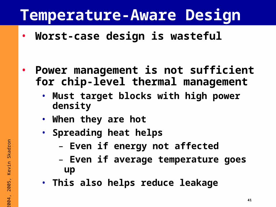
Temperature-Aware Design• Worst-case design is wasteful
• Power management is not sufficient for chip-level thermal management
• Must target blocks with high power density
• When they are hot
• Spreading heat helps
– Even if energy not affected
– Even if average temperature goes up
• This also helps reduce leakage

42
© 2
004,
200
5, K
evin
Ska
dron
Role of Architecture?Dynamic thermal management (DTM)
• Automatic hardware response when temp. exceeds cooling• Cut power density at runtime, on demand• Trade reduced costs for occasional performance loss
• Architecture natural granularity for thermal management• Activity, temperature correlated within arch. units• DTM response can target hottest unit: permits
fine-tuned response compared to OS or package• Modern architectures offer rich opportunities for
remapping computation– e.g., CMPs/SoCs, graphics processors, tiled architectures
– e.g., register file
43
© 2
004,
200
5, K
evin
Ska
dron
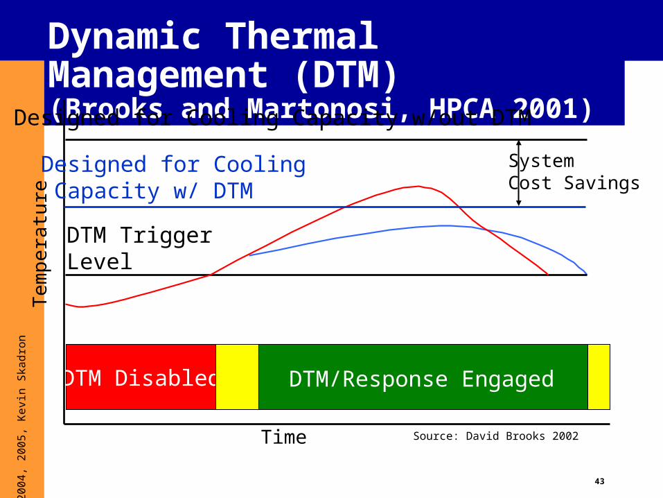
Dynamic Thermal Management (DTM)(Brooks and Martonosi, HPCA 2001)
Time
Tem
pera
ture
DTM Disabled DTM/Response Engaged
Designed for Cooling Capacity w/out DTM
DTM TriggerLevel
Designed for Cooling Capacity w/ DTM
SystemCost Savings
Source: David Brooks 2002
44
© 2
004,
200
5, K
evin
Ska
dron
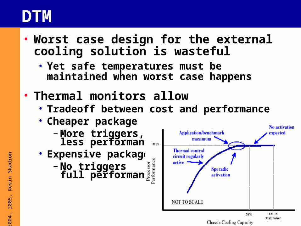
DTM• Worst case design for the external cooling
solution is wasteful• Yet safe temperatures must be maintained when
worst case happens
• Thermal monitors allow• Tradeoff between cost and performance• Cheaper package
– More triggers,less performance
• Expensive package– No triggers
full performance
45
© 2
004,
200
5, K
evin
Ska
dron
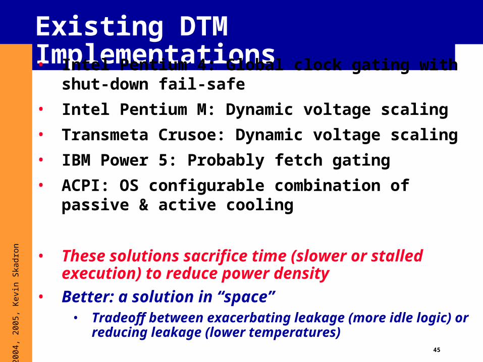
Existing DTM Implementations• Intel Pentium 4: Global clock gating with
shut-down fail-safe
• Intel Pentium M: Dynamic voltage scaling
• Transmeta Crusoe: Dynamic voltage scaling
• IBM Power 5: Probably fetch gating
• ACPI: OS configurable combination of passive & active cooling
• These solutions sacrifice time (slower or stalled execution) to reduce power density
• Better: a solution in “space”• Tradeoff between exacerbating leakage (more idle logic) or
reducing leakage (lower temperatures)
46
© 2
004,
200
5, K
evin
Ska
dron
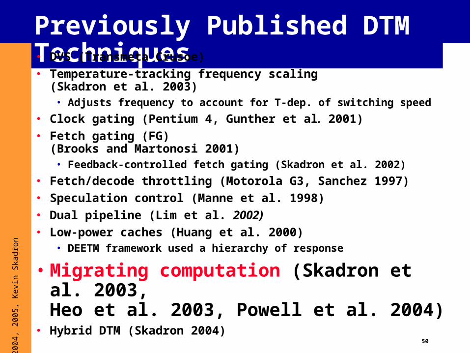
Previously Published DTM Techniques• DVS (Transmeta Crusoe)• Temperature-tracking frequency scaling
(Skadron et al. 2003)• Adjusts frequency to account for T-dep. of switching speed
• Clock gating (Pentium 4, Gunther et al. 2001)• Fetch gating (FG)
(Brooks and Martonosi 2001)• Feedback-controlled fetch gating (Skadron et al. 2002)
• Fetch/decode throttling (Motorola G3, Sanchez 1997)• Speculation control (Manne et al. 1998)• Dual pipeline (Lim et al. 2002)• Low-power caches (Huang et al. 2000)
• DEETM framework used a hierarchy of response
• Migrating computation (Skadron et al. 2003, Heo et al. 2003, Powell et al. 2004)
• Hybrid DTM (Skadron 2004)
47
© 2
004,
200
5, K
evin
Ska
dron
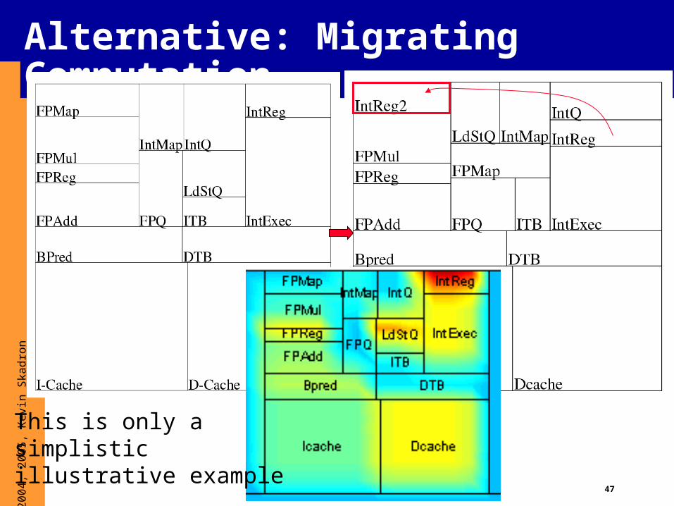
Alternative: Migrating Computation
This is only a simplistic illustrative example
48
© 2
004,
200
5, K
evin
Ska
dron
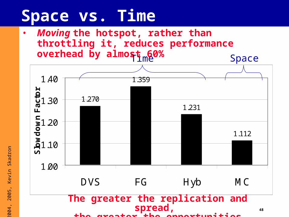
Space vs. Time• Moving the hotspot, rather than throttling it,
reduces performance overhead by almost 60%
1.270
1.359
1.231
1.112
1.00
1.10
1.20
1.30
1.40
DVS FG Hyb MC
Slo
wd
ow
n F
ac
tor
Time Space
The greater the replication and spread,
the greater the opportunities
49
© 2
004,
200
5, K
evin
Ska
dron
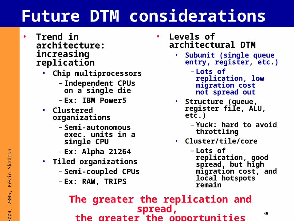
Future DTM considerations• Trend in architecture:
increasing replication• Chip multiprocessors
– Independent CPUs on a single die
– Ex: IBM Power5• Clustered
organizations– Semi-autonomous
exec. units in a single CPU
– Ex: Alpha 21264• Tiled organizations
– Semi-coupled CPUs
– Ex: RAW, TRIPS
• Levels of architectural DTM
• Subunit (single queue entry, register, etc.)
– Lots of replication, low migration cost not spread out
• Structure (queue, register file, ALU, etc.)
– Yuck: hard to avoid throttling
• Cluster/tile/core– Lots of replication,
good spread, but high migration cost, and local hotspots remain
The greater the replication and spread,
the greater the opportunities
50
© 2
004,
200
5, K
evin
Ska
dron
Previously Published DTM Techniques• DVS (Transmeta Crusoe)
• Temperature-tracking frequency scaling (Skadron et al. 2003)
• Adjusts frequency to account for T-dep. of switching speed
• Clock gating (Pentium 4, Gunther et al. 2001)
• Fetch gating (FG)(Brooks and Martonosi 2001)
• Feedback-controlled fetch gating (Skadron et al. 2002)
• Fetch/decode throttling (Motorola G3, Sanchez 1997)
• Speculation control (Manne et al. 1998)
• Dual pipeline (Lim et al. 2002)
• Low-power caches (Huang et al. 2000)• DEETM framework used a hierarchy of response
• Migrating computation (Skadron et al. 2003, Heo et al. 2003, Powell et al. 2004)
• Hybrid DTM (Skadron 2004)
51
© 2
004,
200
5, K
evin
Ska
dron
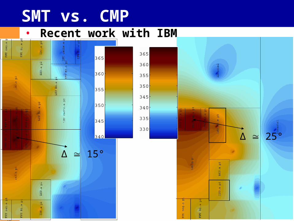
SMT vs. CMP• Recent work with IBM
Δ 15°
Δ 25°
52
© 2
004,
200
5, K
evin
Ska
dron
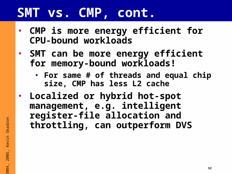
SMT vs. CMP, cont.• CMP is more energy efficient for CPU-bound
workloads
• SMT can be more energy efficient for memory-bound workloads!
• For same # of threads and equal chip size, CMP has less L2 cache
• Localized or hybrid hot-spot management, e.g. intelligent register-file allocation and throttling, can outperform DVS
53
© 2
004,
200
5, K
evin
Ska
dron
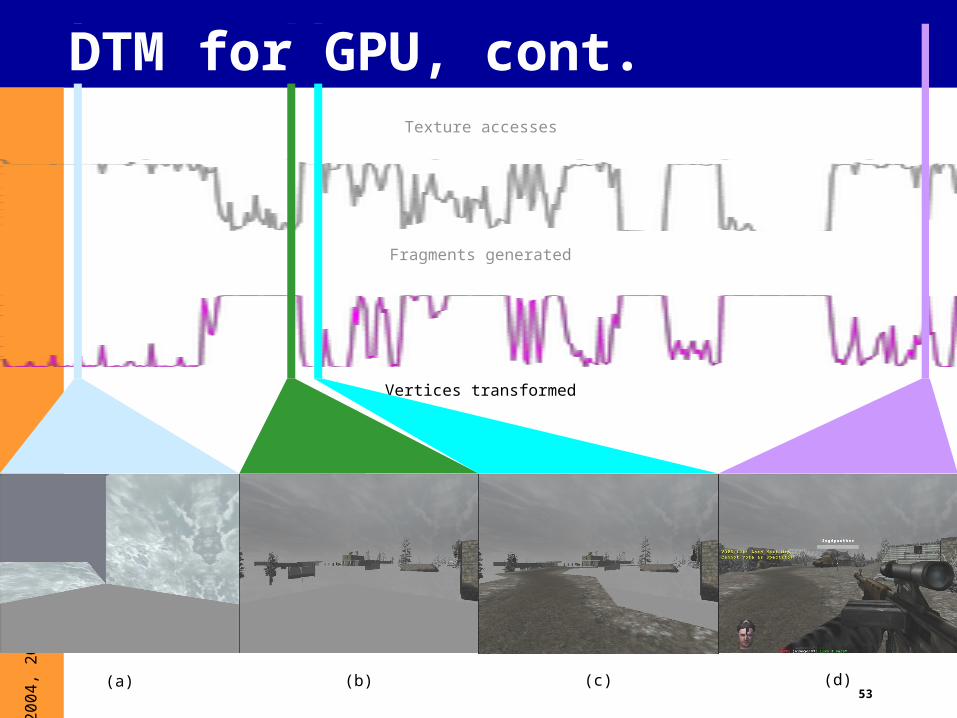
Vertices transformed
Fragments generated
Texture accesses
(a) (b) (c) (d)
DTM for GPU, cont.
54
© 2
004,
200
5, K
evin
Ska
dron
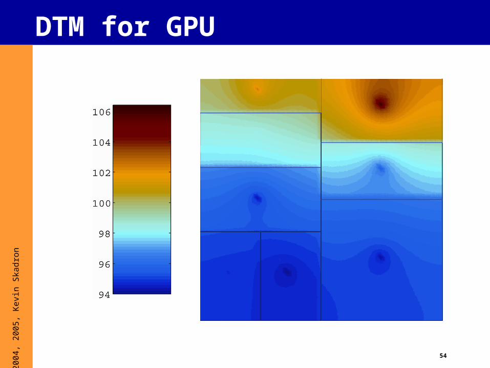
DTM for GPU
55
© 2
004,
200
5, K
evin
Ska
dron
Overview
1. What is thermal?
2. Why thermal?
3. Why should architects care?
4. Useful thermal background5. Dynamic thermal mgmt. (DTM)
- Prelim CMP, SMT, and GPU results
6. Thermal Modeling and HotSpot
7. Sensor issues
8. Some research questions

56
© 2
004,
200
5, K
evin
Ska
dron
Thermal modeling
• Want a fine-grained, dynamic model of temperature• At a granularity architects can reason about• That accounts for adjacency and package• That does not require detailed designs• That is fast enough for practical use
• HotSpot - a compact model based on thermal R, C• Parameterized to automatically derive a model
based on various– Architectures– Power models– Floorplans– Thermal Packages

57
© 2
004,
200
5, K
evin
Ska
dron
Dynamic compact thermal model
Electrical-thermal duality
V temp (T)
I power (P)
R thermal resistance (Rth)
C thermal capacitance (Cth)
RC time constant (Rth Cth)
Kirchoff Current Law
differential eq. I = C · dV/dt + V/R
thermal domain P = Cth · dT/dt + T/Rth
where T = T_hot – T_amb
At higher granularities of P, Rth, Cth
P, T are vectors and Rth, Cth are circuit matrices
T_hot
T_amb

58
© 2
004,
200
5, K
evin
Ska
dron
Example System
Heat sink
Heat spreader
PCB
Die
IC Package
Pin
Interface material
59
© 2
004,
200
5, K
evin
Ska
dron
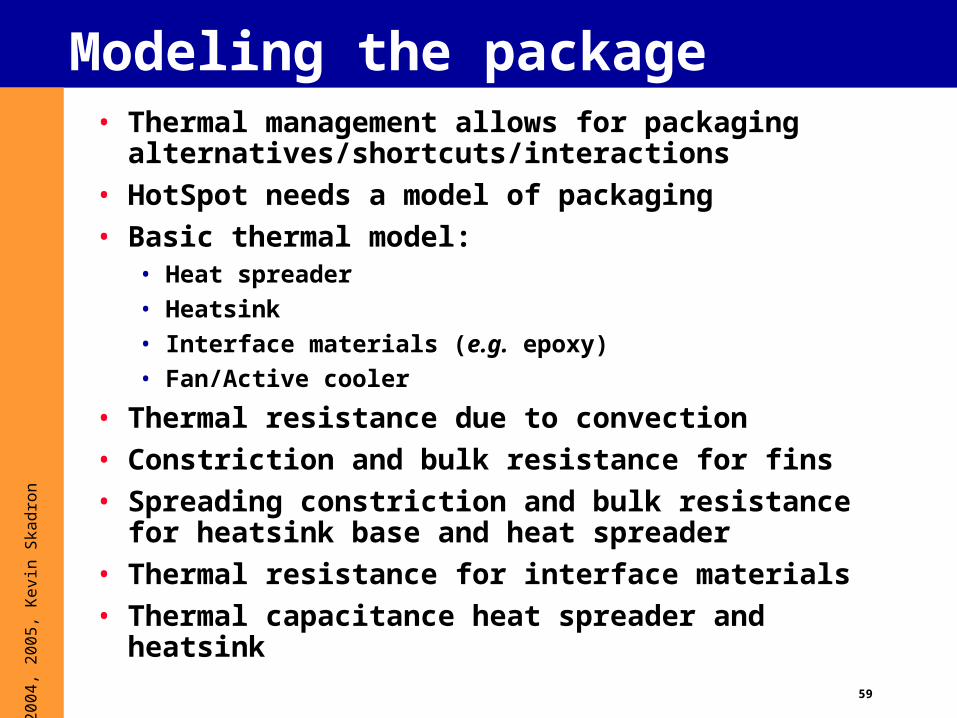
Modeling the package• Thermal management allows for packaging
alternatives/shortcuts/interactions
• HotSpot needs a model of packaging
• Basic thermal model:• Heat spreader
• Heatsink
• Interface materials (e.g. epoxy)
• Fan/Active cooler
• Thermal resistance due to convection
• Constriction and bulk resistance for fins
• Spreading constriction and bulk resistance for heatsink base and heat spreader
• Thermal resistance for interface materials
• Thermal capacitance heat spreader and heatsink
60
© 2
004,
200
5, K
evin
Ska
dron
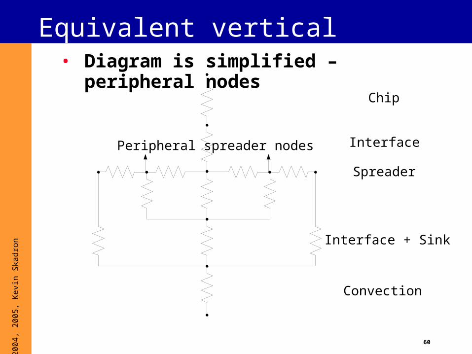
Equivalent vertical network
Chip
Interface
Spreader
Interface + Sink
Convection
Peripheral spreader nodes
• Diagram is simplified – peripheral nodes
61
© 2
004,
200
5, K
evin
Ska
dron
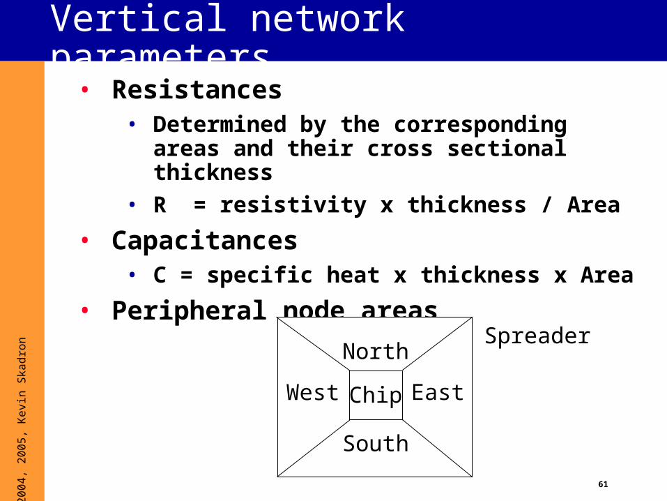
Vertical network parameters• Resistances
• Determined by the corresponding areas and their cross sectional thickness
• R = resistivity x thickness / Area
• Capacitances• C = specific heat x thickness x Area
• Peripheral node areas
Chip
SpreaderNorth
South
EastWest
62
© 2
004,
200
5, K
evin
Ska
dron
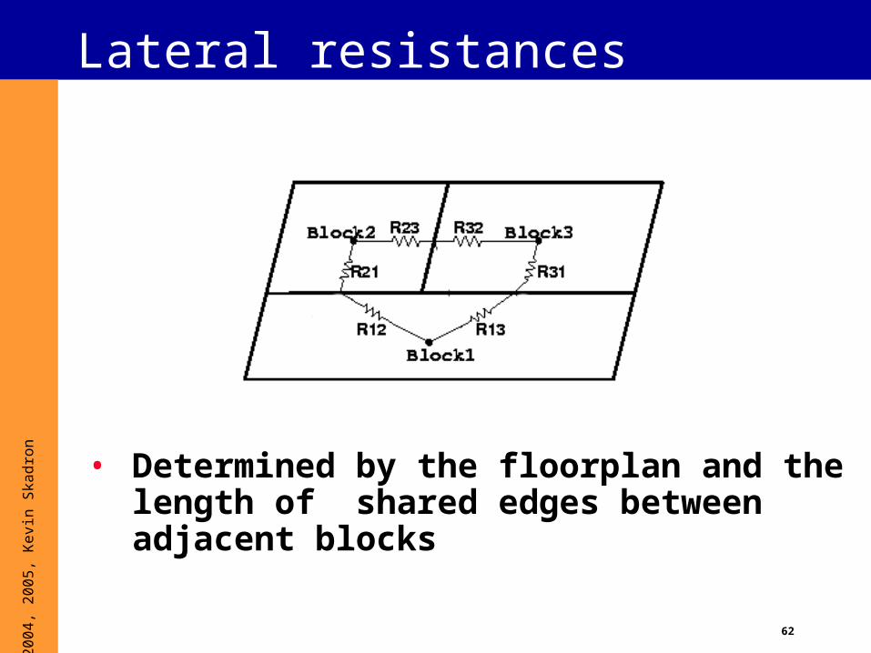
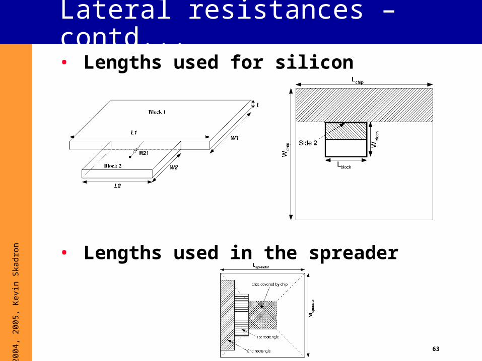
Lateral resistances
• Determined by the floorplan and the length of shared edges between adjacent blocks
63
© 2
004,
200
5, K
evin
Ska
dron
Lateral resistances – contd...• Lengths used for silicon
• Lengths used in the spreader
64
© 2
004,
200
5, K
evin
Ska
dron
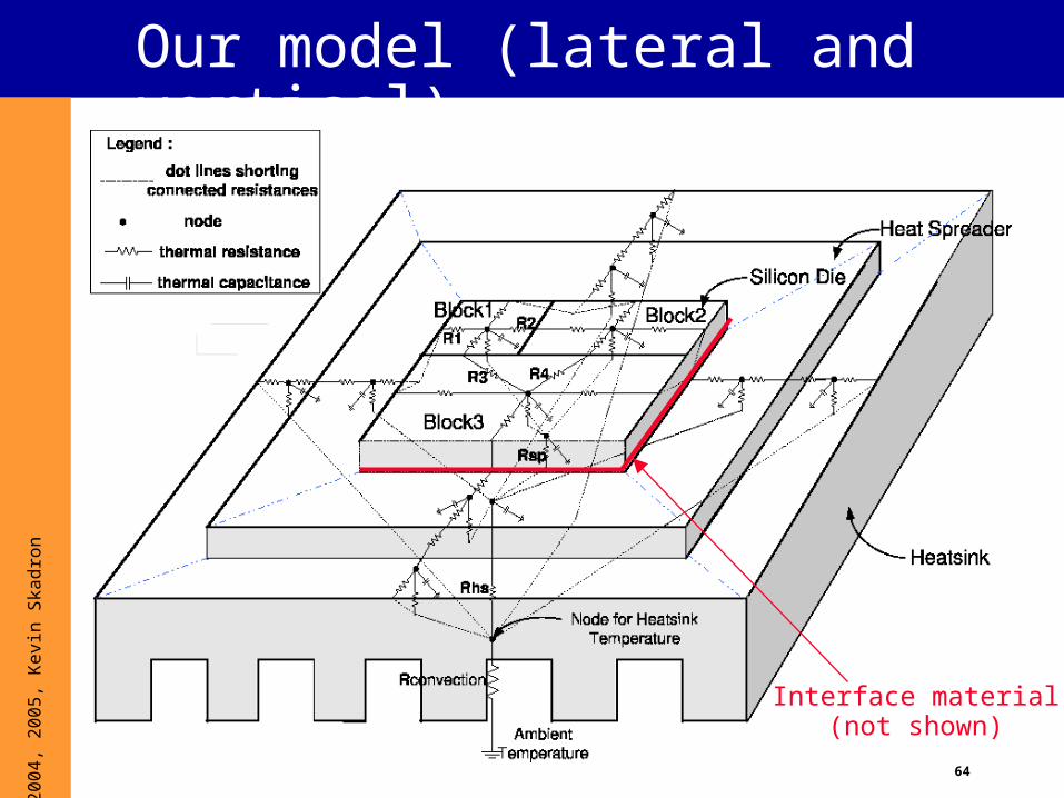
Our model (lateral and vertical)
Interface material(not shown)
65
© 2
004,
200
5, K
evin
Ska
dron
Temperature equations• Fundamental RC differential equation
• P = C dT/dt + T / R
• Steady state• dT/dt = 0
• P = T / R
• When R and C are network matrices• Steady state – T = R x P
• Modified transient equation
– dT/dt + (RC)-1 x T = C-1 x P
• HotSpot software mainly solves thesetwo equations

66
© 2
004,
200
5, K
evin
Ska
dron
HotSpot
• Time evolution of temperature is driven by unit activities and power dissipations averaged over 10K cycles• Power dissipations can come from any power
simulator, act as “current sources” in RC circuit ('P' vector in the equations)
• Simulation overhead in Wattch/SimpleScalar: <1%
• Requires models of• Floorplan: important for adjacency
• Package: important for spreading and time constants
• R and C matrices are derived from the above

67
© 2
004,
200
5, K
evin
Ska
dron
Implementation• Primarily a circuit solver
• Steady state solution • Mainly matrix inversion – done in two steps
– Decomposition of the matrix into lower and upper triangular matrices
– Successive backward substitution of solved variables
• Implements the pseudocode from CLR
• Transient solution• Inputs – current temperature and power
• Output – temperature for the next interval
• Computed using a fourth order Runge-Kutta (RK4) method
68
© 2
004,
200
5, K
evin
Ska
dron
Transient solution• Solves differential equations of the form dT + AT =
B where A and B are constants• In HotSpot, A is constant (RC) but B depends on the
power dissipation
• Solution – assume constant average power dissipation within an interval (10 K cycles) and call RK4 at the end of each interval
• In RK4, current temperature (at t) is advanced in very small steps (t+h, t+2h ...) till the next interval (10K cycles)
• RK – `4` because error term is 4th order i.e., O(h^4)

69
© 2
004,
200
5, K
evin
Ska
dron
Transient solution contd...• 4th order error has to be within the required
precision
• The step size (h) has to be small enough even for the maximum slope of the temperature evolution curve
• Transient solution for the differential equation is of the form Ae-Bt with A and B are dependent on the RC network
• Thus, the maximum value of the slope (AxB) and the step size are computed accordingly
70
© 2
004,
200
5, K
evin
Ska
dron
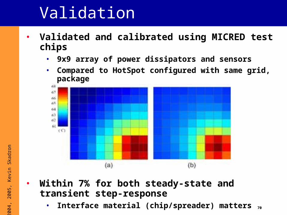
Validation• Validated and calibrated using MICRED test chips
• 9x9 array of power dissipators and sensors
• Compared to HotSpot configured with same grid, package
• Within 7% for both steady-state and transient step-response
• Interface material (chip/spreader) matters

71
© 2
004,
200
5, K
evin
Ska
dron
Validation (cont.)• Also validated against an FPGA
• Can instantiate a temp. sensor based on a ring oscillator and counter
• Also validated against IBM AnSYS FEM simulations

72
© 2
004,
200
5, K
evin
Ska
dron
Notes• Note that HotSpot currently measures
temperaturesin the silicon
• But that’s also what the most sensors measure
• Temperature continues to rise through each layer of the die
• Temperature in upper-level metal is considerably higher
• Interconnect model forthcoming
73
© 2
004,
200
5, K
evin
Ska
dron
Soon to be features• Grid model – RC network per grid cell instead of a
block• Straightforward extension of “lumpy model”, but regular
and easier to accelerate the computation
• Multigrid algorithm for faster convergence with very small elements
• Temperature models for wires, pads and interface material between heat sink and spreader
• See DAC’04 paper
• Better (more user friendly) floorplan specification
• Automatic floorplan generation using classical floorplanning algorithms
• Interface for package selection

74
© 2
004,
200
5, K
evin
Ska
dron
HotSpot Summary
• HotSpot is a simple, accurate and fast architecture level thermal model for microprocessors
• Over 350 downloads since June’03
• Ongoing active development – architecture level floorplanning will be available soon
• Download site• http://lava.cs.virginia.edu/HotSpot
• Mailing list• www.cs.virginia.edu/mailman/listinfo/hotspot
75
© 2
004,
200
5, K
evin
Ska
dron
Overview
1. What is thermal?
2. Why thermal?
3. Why should architects care?
4. Useful thermal background5. Dynamic thermal mgmt. (DTM)
- Prelim CMP, SMT, and GPU results
6. Thermal Modeling
7. Sensor issues
8. Some research questions
76
© 2
004,
200
5, K
evin
Ska
dron
Sensors
Caveat emptor:
We are not well-versed on sensor design; the following is a digest of information we have been able to collect from industry sources and the research literature.
77
© 2
004,
200
5, K
evin
Ska
dron
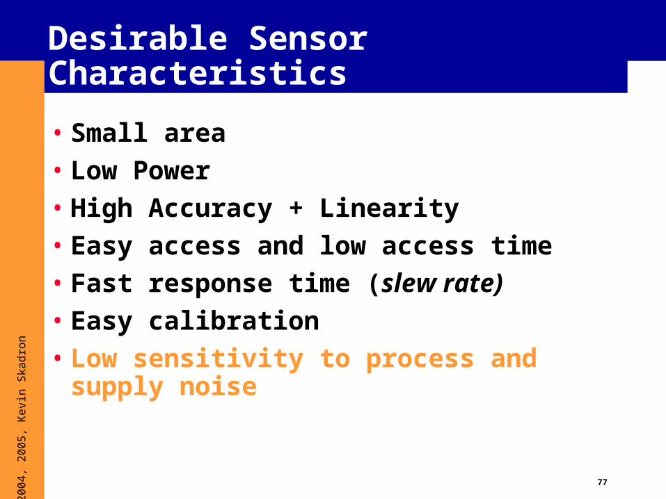
Desirable Sensor Characteristics
• Small area
• Low Power
• High Accuracy + Linearity
• Easy access and low access time
• Fast response time (slew rate)
• Easy calibration
• Low sensitivity to process and supply noise
78
© 2
004,
200
5, K
evin
Ska
dron
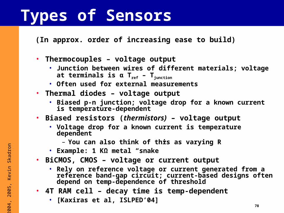
Types of Sensors(In approx. order of increasing ease to build)
• Thermocouples – voltage output• Junction between wires of different materials; voltage at
terminals is α Tref – Tjunction
• Often used for external measurements• Thermal diodes – voltage output
• Biased p-n junction; voltage drop for a known current is temperature-dependent
• Biased resistors (thermistors) – voltage output• Voltage drop for a known current is temperature dependent
– You can also think of this as varying R• Example: 1 KΩ metal “snake”
• BiCMOS, CMOS – voltage or current output• Rely on reference voltage or current generated from a reference
band-gap circuit; current-based designs often depend on temp-dependence of threshold
• 4T RAM cell – decay time is temp-dependent• [Kaxiras et al, ISLPED’04]

79
© 2
004,
200
5, K
evin
Ska
dron
Sensors: Problem Issues
• Poor control of CMOS transistor parameters
• Noisy environment• Cross talk
• Ground noise
• Power supply noise
• These can be reduced by making the sensor larger• This increases power dissipation
• But we may want many sensors
80
© 2
004,
200
5, K
evin
Ska
dron
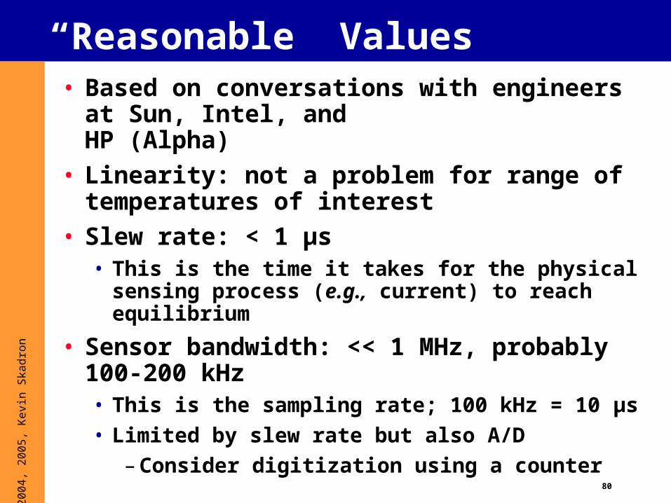
“Reasonable” Values• Based on conversations with engineers at
Sun, Intel, and HP (Alpha)
• Linearity: not a problem for range of temperatures of interest
• Slew rate: < 1 μs• This is the time it takes for the physical sensing
process (e.g., current) to reach equilibrium
• Sensor bandwidth: << 1 MHz, probably 100-200 kHz• This is the sampling rate; 100 kHz = 10 μs
• Limited by slew rate but also A/D
– Consider digitization using a counter

81
© 2
004,
200
5, K
evin
Ska
dron
• Mid 1980s: < 0.1° was possible
• Precision• ± 3° is very reasonable
• ± 2° is reasonable
• ± 1° is feasible but expensive
• < ± 1° is really hard
• The limited precision of the G3 sensor seems to have been a design choice involving the digitization
“Reasonable” Values: Precision
P: 10s of mW
82
© 2
004,
200
5, K
evin
Ska
dron
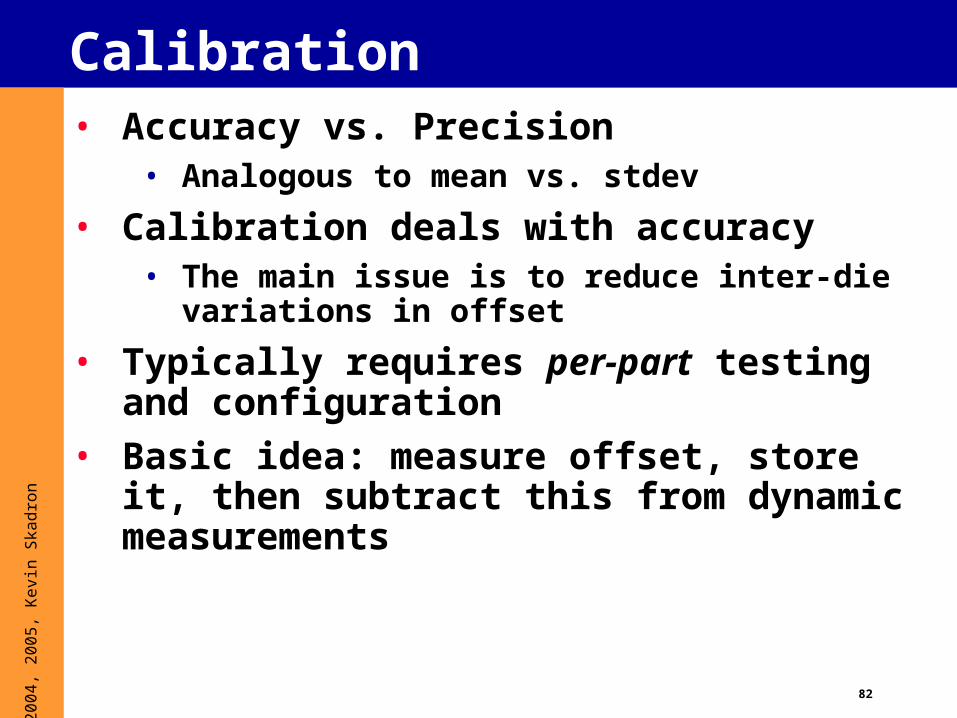
Calibration• Accuracy vs. Precision
• Analogous to mean vs. stdev
• Calibration deals with accuracy• The main issue is to reduce inter-die variations
in offset
• Typically requires per-part testing and configuration
• Basic idea: measure offset, store it, then subtract this from dynamic measurements

83
© 2
004,
200
5, K
evin
Ska
dron
Dynamic Offset Cancelation• Rich area of research
• Build circuit to continuously, dynamically detect offset and cancel it
• Typically uses an op-amp
• Has the advantage that it adapts to changing offsets
• Has the disadvantage of more complex circuitry
84
© 2
004,
200
5, K
evin
Ska
dron
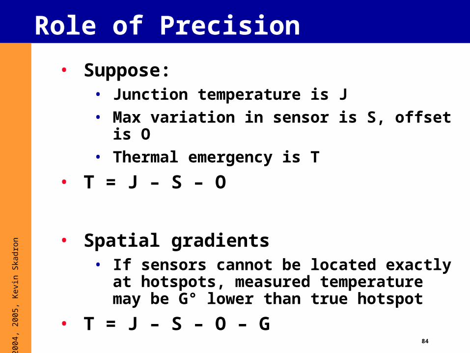
Role of Precision
• Suppose:• Junction temperature is J
• Max variation in sensor is S, offset is O
• Thermal emergency is T
• T = J – S – O
• Spatial gradients• If sensors cannot be located exactly at
hotspots, measured temperature may be G° lower than true hotspot
• T = J – S – O – G
85
© 2
004,
200
5, K
evin
Ska
dron
Rate of change of temperature
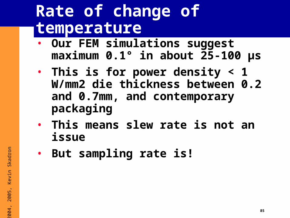
• Our FEM simulations suggest maximum 0.1° in about 25-100 μs
• This is for power density < 1 W/mm2 die thickness between 0.2 and 0.7mm, and contemporary packaging
• This means slew rate is not an issue
• But sampling rate is!
86
© 2
004,
200
5, K
evin
Ska
dron
Sensors Summary
• Sensor precision cannot be ignored• Reducing operating threshold by 1-2 degrees
will affect performance
• Precision of 1° is conceivable but expensive• Maybe reasonable for a single sensor or a few
• Precision of 2-3° is reasonable even for a moderate number of sensors
• Power and area are probably negligible from the architecture standpoint
• Sampling period <= 10-20 μs
87
© 2
004,
200
5, K
evin
Ska
dron
Current features
• Specification of arbitrary floorplans
• Format of floorplan file:• One line per unit
• Line format – <unit-name> \t <width> \t <height> \t <left-x> \t <bottom-y> \n
• Takes a power trace file as an input and outputs corresponding temperature trace
• Ability to modify package specifactions (type of interface material, size and type of heat spreader and heat sink etc.)

88
© 2
004,
200
5, K
evin
Ska
dron
Better floorplan specification• Floorplan of current microprocessors has
a structural similarity
• Floorplans similar to MIPS R10K, Pentium and the Alpha 21264
• Pipeline order corresponds to floorplan adjacency

89
© 2
004,
200
5, K
evin
Ska
dron
Better floorplan specification
• Sample specification (with % areas) that takes advantage of pipeline order

90
© 2
004,
200
5, K
evin
Ska
dron
Automatic floorplan for architects
• Why develop an architectural floorplanning tool?• Thermal modeling requires adjacency
information.• Wire delays make performance depend on the
floorplan.
• Goal• Derive a realistic floorplan using only
microarchitectural information• Trade off thermal efficiency against latency• Simulated annealing based floorplan
optimization for thermal, delay and combined metrics
• Current work. Results will be available soon

91
© 2
004,
200
5, K
evin
Ska
dron
Overview
1. What is thermal?
2. Why thermal?
3. Why should architects care?
4. Useful thermal background5. Dynamic thermal mgmt. (DTM)
- Prelim CMP, SMT, and GPU results
6. Thermal Modeling
7. Sensor issues
8. Some research questions

92
© 2
004,
200
5, K
evin
Ska
dron
Future Work• Modeling
• Accelerated or sampled simulation for multiprogrammed and multi-core simulation
• Metrics• Quantify tradeoffs among performance loss,
energy costs, and cooling costs
• Explore relationship between thermal, leakage
• Also other physical phenomena, e.g. parameter variations
93
© 2
004,
200
5, K
evin
Ska
dron
Future Work: DTM• Connect thermal management to OS knowledge of
application requirements• Allows predictive rather than reactive response
• Runtime phase prediction and runtime profiling can also permit predictive response
• Spread heat across the CPU, e.g. compiler techniques
• Exploit opportunities for migration in architectures with remapping – rich design space
• eg, CMP, clusters, TRIPS
• Sensor fusion to reduce sensor imprecision• As much as 50% of DTM overhead is due to sensors
• Might use many small, cheap, imprecise sensors
• Very interesting paper at ISLPED: 4T RAM as sensor
• Need to better understand sensor placement
94
© 2
004,
200
5, K
evin
Ska
dron
Recap• Opportunity and need for temperature-aware design
• Compact models are a natural modeling abstraction• Applicable in all design stages
• The microarchitecture is a natural domain in which to control on-chip temperature
• ILP matters• Microarchitecture techniques can outperform DVS• Tiled/clustered/reconfigurable/etc. architectures offer a rich
design space
• Need to understand the multi-dimensional problem of power, leakage, reliability, and temperature management
• Need designs that prevent hotspots