Embed Size (px)
Citation preview
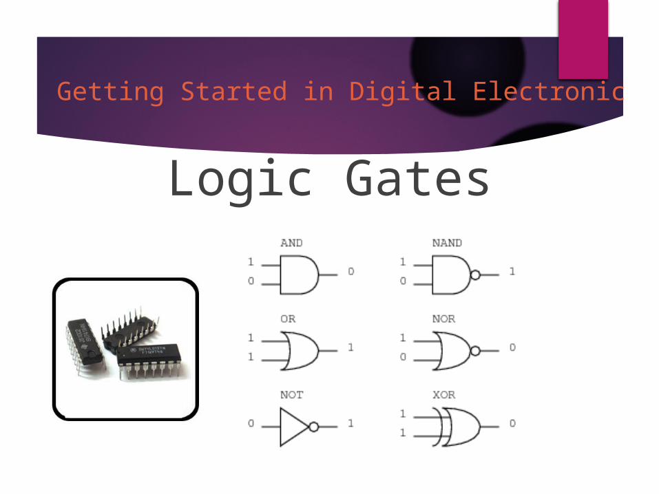
Logic GatesGetting Started in Digital Electronic
Logic Gates
Goal: To understand how digital a computer can work, at
the lowest level. To understand what is possible and the limitations of
what is possible for a digital computer.
Logic Gates
All digital computers for the past 50 years have been constructed using the same type of components.
These components are called logic gates. Logic gates have been implemented in
many different ways. Currently, logic gates are most commonly
implemented using electronic VLSI transistor logic.
Logic Gates
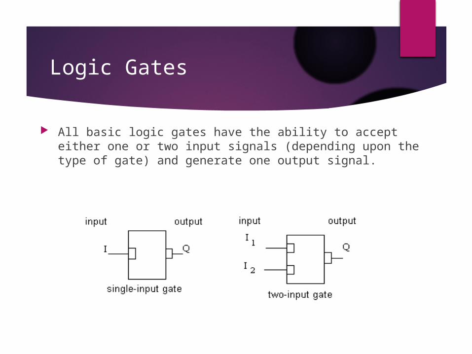
All basic logic gates have the ability to accept either one or two input signals (depending upon the type of gate) and generate one output signal.
Logic Gates
Input and Output signals are binary. binary:
always in one of two possible states; typically treated as:
On / Off (electrically) 1 / 0 True / False
The True or False view is most useful for thinking about the meaning of the basic logic gates.
Logic Gates
The six basic logic gates are: AND OR XOR NOT NAND NOR
Each of these gates may be drawn in either A generic form; or An electrical engineering form (more common in text books)
Logic Gates : AND
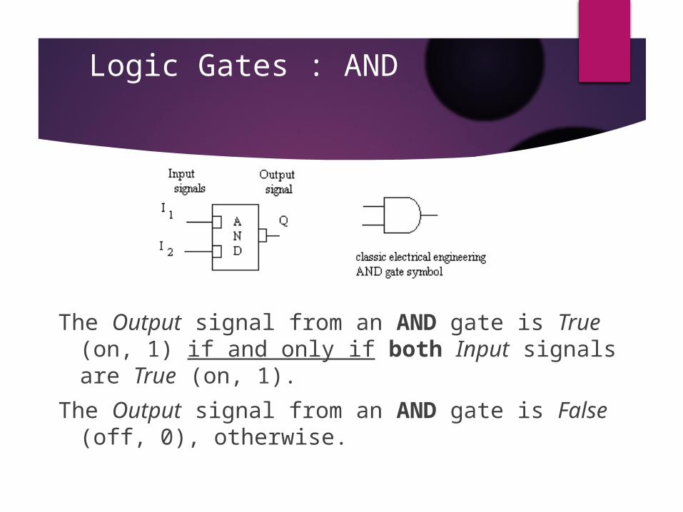
The Output signal from an AND gate is True (on, 1) if and only if both Input signals are True (on, 1).
The Output signal from an AND gate is False (off, 0), otherwise.
Logic Gates : OR
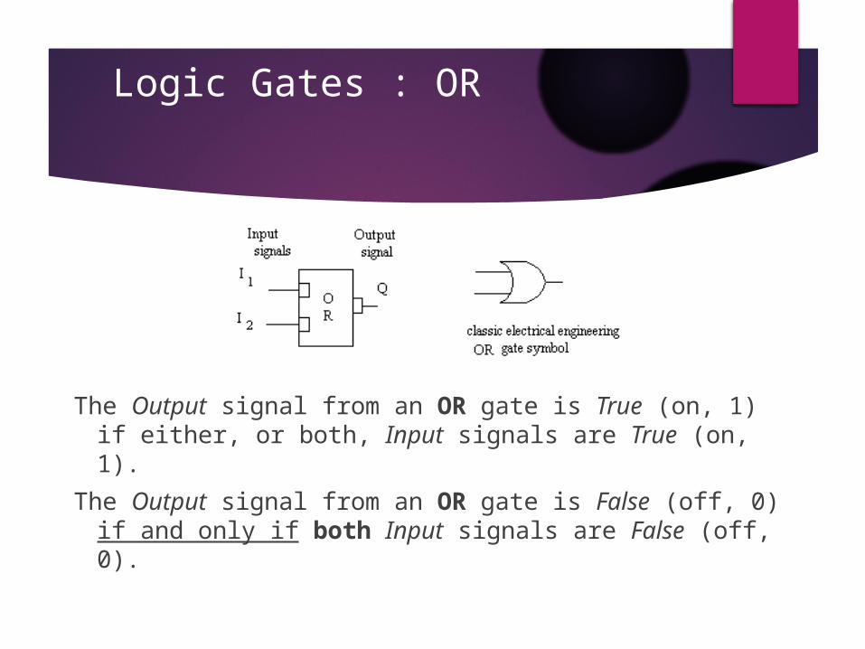
The Output signal from an OR gate is True (on, 1) if either, or both, Input signals are True (on, 1).
The Output signal from an OR gate is False (off, 0) if and only if both Input signals are False (off, 0).
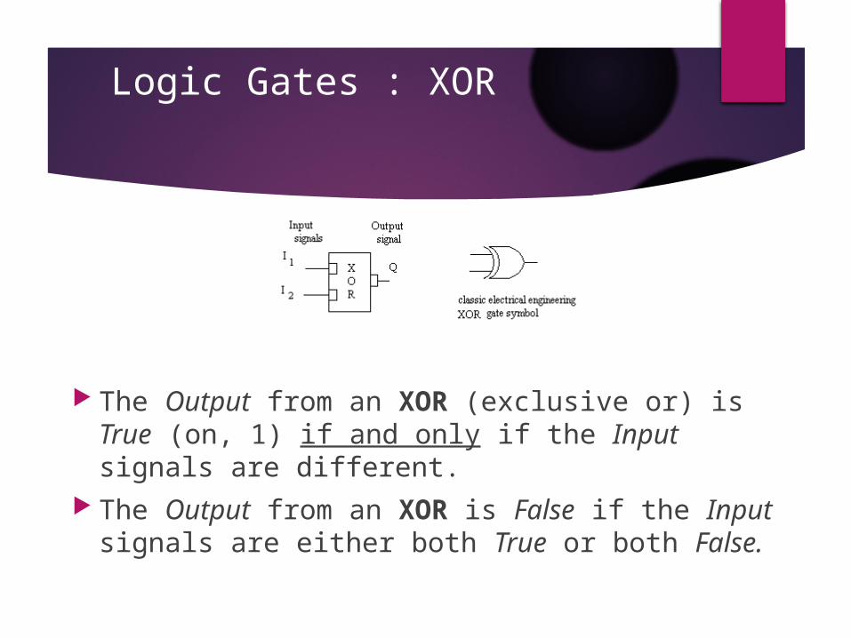
Logic Gates : XOR
The Output from an XOR (exclusive or) is True (on, 1) if and only if the Input signals are different.
The Output from an XOR is False if the Input signals are either both True or both False.
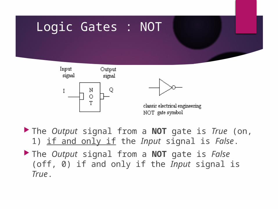
Logic Gates : NOT
The Output signal from a NOT gate is True (on, 1) if and only if the Input signal is False.
The Output signal from a NOT gate is False (off, 0) if and only if the Input signal is True.
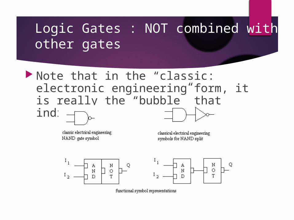
Logic Gates : NOT combined with other gates
Note that in the “classic: electronic engineering form, it is really the “bubble” that indicates the NOT activity.
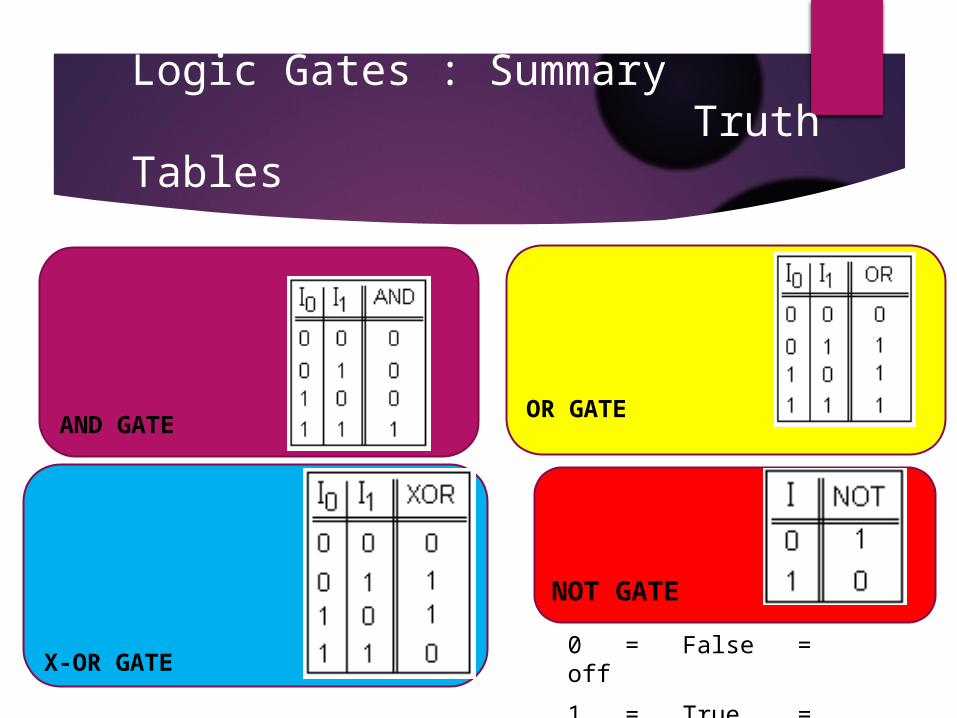
Logic Gates : Summary Truth Tables
0 = False = off1 = True = on
A BA B
A B A
AND GATE OR GATE
X-OR GATE
NOT GATE
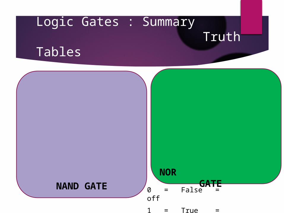
Logic Gates : Summary Truth Tables
0 = False = off1 = True = on
NAND GATENOR GATE


![Gates and Logic: From Transistors to Logic Gates and Logic ......Gates and Logic: From Transistors to Logic Gates and Logic Circuits [Weatherspoon, Bala, Bracy, and Sirer] Prof. Hakim](https://img.pdfslide.us/doc/110x75/5fa95cb6eb1af8231472f381/gates-and-logic-from-transistors-to-logic-gates-and-logic-gates-and-logic.jpg)