Embed Size (px)
Citation preview
SURFACE ENGINEERING
EFFECTS OF DIFFERENT ALLOYING ELEMENTS ON THE HARDNESS PROFILEOF NITRIDED HOT-WORK TOOL STEELSR. Schneider, H. Schweiger, G. Reiter, V. Strobl . . . . . . . . . . . . . . . . . . . . . . . . . . . . . . . . . . . . . . . . . . . . . . . . . . . . . . . . . . .113
STUDY ON CORROSION OF CHROMIUM NITRIDE AND TITANIUM NITRIDECOATINGS IN LIQUID ALUMINIUMG. Negrea, H. Vermesan, V. Rus . . . . . . . . . . . . . . . . . . . . . . . . . . . . . . . . . . . . . . . . . . . . . . . . . . . . . . . . . . . . . . . . . . . . . . .119
NITRIDED IRON ALUMINDE - A NEW MATERIAL FOR HOT WORKING TOOLSA. Fischer, H.-J. Spies, H. Biermann, M. Staia . . . . . . . . . . . . . . . . . . . . . . . . . . . . . . . . . . . . . . . . . . . . . . . . . . . . . . . . . . . .125
THE INFLUENCE OF BIAS AND IN-SITU CLEANING ON THROUGH CAGE (TC)OR ACTIVE SCREEN PLASMA NITRIDED (ASPN) STEELSP. Hubbard, S. J. Dowey, E. D. Doyle, D. G. McCulloch . . . . . . . . . . . . . . . . . . . . . . . . . . . . . . . . . . . . . . . . . . . . . . . . . . . . .131
INDENTATION FRACTURE TESTING OF NITRIDED LAYERS ON H11 TOOL STEELD. Nolan, V. Leskovsek, M. Jenko . . . . . . . . . . . . . . . . . . . . . . . . . . . . . . . . . . . . . . . . . . . . . . . . . . . . . . . . . . . . . . . . . . . . . .137
VACUUM OXYCARBONITRIDING OF ARTICLES OF X12 TOOL STEELP. Danev, D. Gospodinov, R. Radeva . . . . . . . . . . . . . . . . . . . . . . . . . . . . . . . . . . . . . . . . . . . . . . . . . . . . . . . . . . . . . . . . . . . .145
THE MECHANICAL PROPERTIES OF TOOL STEELS WITH DIFFUSION CARBONAND NITROCARBON LAYERS T. Babul, N. Kucharieva, A. Nakonieczny, J. Senatorski . . . . . . . . . . . . . . . . . . . . . . . . . . . . . . . . . . . . . . . . . . . . . . . . . . . . .151
COMBINATION OF MILLING AND LASER BEAM MACHINING - FOR MOULD MAKINGH.-J. Pieper, E. Wolf, M. Krause . . . . . . . . . . . . . . . . . . . . . . . . . . . . . . . . . . . . . . . . . . . . . . . . . . . . . . . . . . . . . . . . . . . . . . . .159
TRIBOLOGICAL PROPERTIES OF SURFACE ENGINEERED HOT WORK TOOLSTEEL FOR ALUMINIUM EXTRUSION DIESM. Pellizzari, M. Zadra, A. Molinari . . . . . . . . . . . . . . . . . . . . . . . . . . . . . . . . . . . . . . . . . . . . . . . . . . . . . . . . . . . . . . . . . . . . . .165
HARD COATINGS TO PREVENT THE WASHOUT PHENOMENA IN HIGHPRESSURE DIE CASTING TOOLSD. Ugues, E. Torres Miranda, M. Perucca, M. Albertinazzi, M. Rosso . . . . . . . . . . . . . . . . . . . . . . . . . . . . . . . . . . . . . . . . . . .173
STATUS QUO OF TRD COATING APPLICATION IN THE WORLDT. Arai . . . . . . . . . . . . . . . . . . . . . . . . . . . . . . . . . . . . . . . . . . . . . . . . . . . . . . . . . . . . . . . . . . . . . . . . . . . . . . . . . . . . . . . . . . . .179
IMPROVEMENT OF HOT WORK STEEL WEAR RESISTANCE BYPLASMA NITRIDING AND PVD COATINGSL.A. Dobrzañski, M. Polok, M. Adamiak , M. G. Faga . . . . . . . . . . . . . . . . . . . . . . . . . . . . . . . . . . . . . . . . . . . . . . . . . . . . .185
IMPROVEMENT IN GALLING PERFORMANCE THROUGH SURFACE ENGINEERINGB. Podgornik, J. Vižintin, S. Hogmark . . . . . . . . . . . . . . . . . . . . . . . . . . . . . . . . . . . . . . . . . . . . . . . . . . . . . . . . . . . . . . . . . . .191
ADVANCED APPLICATIONS OF PVD AND CVD COATINGS IN AUTOMOTIVEINDUSTRY: CUTTING TOOLS AND DIESS. Durante, D. Franchi, M. Rostagno . . . . . . . . . . . . . . . . . . . . . . . . . . . . . . . . . . . . . . . . . . . . . . . . . . . . . . . . . . . . . . . . . . . .199
HARDIDE™ - ADVANCED CVD COATING FOR TOOLS AND DIESY. N. Zhuk . . . . . . . . . . . . . . . . . . . . . . . . . . . . . . . . . . . . . . . . . . . . . . . . . . . . . . . . . . . . . . . . . . . . . . . . . . . . . . . . . . . . . . . . .205
COMPARISON OF MECHANICAL PROPERTIES OF VARIOUS PVDHARD COATINGS FOR FORMING TOOLSÐ. Goršæak, P. Panjan, M. Èekada, L. Æurkoviæ . . . . . . . . . . . . . . . . . . . . . . . . . . . . . . . . . . . . . . . . . . . . . . . . . . . . . . . . . . . .211
TESTS OF MATERIALS AND SURFACE TREATMENT TECHNOLOGIES ENHANCINGTHE LIFETIME OF FORMING TOOLSJ. Fajt, Z. £ataœ, P. Motyèka, Z. Rogalski, P. Šuchmann . . . . . . . . . . . . . . . . . . . . . . . . . . . . . . . . . . . . . . . . . . . . . . . . . . . . .217
DIMENSIONAL ANALYSIS IN THE GROWTH KINETICS OF FeB AND Fe2BLAYERS DURING THE BORIDING PROCESSR. Torres, I. Campos, O. Bautista, G. Ramírez, L. Zúniga . . . . . . . . . . . . . . . . . . . . . . . . . . . . . . . . . . . . . . . . . . . . . . . . . . . .223
THERMAL AND THERMOCHEMICAL TREATMENTOF TOOL STEELS IN VACUUMV. Toshkov, A. Ziumbilev . . . . . . . . . . . . . . . . . . . . . . . . . . . . . . . . . . . . . . . . . . . . . . . . . . . . . . . . . . . . . . . . . . . . . . . . . . . . . .229
CONTAINS
DUPLEX LAYERS ON COLD WORKING STEELB. Škoriæ, D. Kakaš, D. Krumes, Z.Kolumbiæ . . . . . . . . . . . . . . . . . . . . . . . . . . . . . . . . . . . . . . . . . . . . . . . . . . . . . . . . . . . .235
DIFFUSION CHROMIZED LAYERS PRODUCED ON IRON AND STEELSURFACE BY MEANS OF CVDE. Kasprzycka, B. Bogdañski . . . . . . . . . . . . . . . . . . . . . . . . . . . . . . . . . . . . . . . . . . . . . . . . . . . . . . . . . . . . . . . . . . . . . . . . . .241
DIFFUSION CHROMIZED LAYERS PRODUCED IN CHROMIUM CHLORIDEATMOSPHERE AT LOW PRESSUREE. Kasprzycka, B. Bogdañski . . . . . . . . . . . . . . . . . . . . . . . . . . . . . . . . . . . . . . . . . . . . . . . . . . . . . . . . . . . . . . . . . . . . . . . . . .247
ANTICARBURISING COATINGS APPLIED ON PARTS OF CARBURISING FURNACESM. Garbiak, B. Piekarski . . . . . . . . . . . . . . . . . . . . . . . . . . . . . . . . . . . . . . . . . . . . . . . . . . . . . . . . . . . . . . . . . . . . . . . . . . . . . .253
NANO TECHNOLOGY FOR SURFACE TREATMENT OF FERROMAGNETIC MATERIALSA. Makedonski , B. Makedonski , S. Troha . . . . . . . . . . . . . . . . . . . . . . . . . . . . . . . . . . . . . . . . . . . . . . . . . . . . . . . . . . . . . . .259
METHODS AND A UNIT FOR NITRIDING, CARBONITRIDINGAND OXYCARBONITRIDING IN VACUUMP. Danev, D. Gospodinov, R. Radeva . . . . . . . . . . . . . . . . . . . . . . . . . . . . . . . . . . . . . . . . . . . . . . . . . . . . . . . . . . . . . . . . . . . .267
GAS NITRIDING OF EN40B STEEL WITH HIGHEST GROWTH RATE OF THE CASEAND REDUCED WHITE LAYER FORMATION.S. Mridha . . . . . . . . . . . . . . . . . . . . . . . . . . . . . . . . . . . . . . . . . . . . . . . . . . . . . . . . . . . . . . . . . . . . . . . . . . . . . . . . . . . . . . . . .273
IMPROVEMENTS IN THERMO REACTIVE DEPOSITION OF CARBIDE LAYERSB. Matijeviæ, M. Stupnišek . . . . . . . . . . . . . . . . . . . . . . . . . . . . . . . . . . . . . . . . . . . . . . . . . . . . . . . . . . . . . . . . . . . . . . . . . . . .281
A NEW APPROACH TO LIFETIME INCREASE OF TOOLS AND DIES BY OPTIMIZEDVACUUM HARDENING AND PLASMA ASSISTED SURFACE TREATMENT PROCESSEST. Müller, V. Strobl, R. Kullmer, M. Stoiber . . . . . . . . . . . . . . . . . . . . . . . . . . . . . . . . . . . . . . . . . . . . . . . . . . . . . . . . . . . . . . . .289
EFFECTS OF THERMOCHEMICAL TREATMENTS ON MARAGING STEEL PROPERTIESF. Cajner, D. Landek, S. Šoliæ, H. Cajner . . . . . . . . . . . . . . . . . . . . . . . . . . . . . . . . . . . . . . . . . . . . . . . . . . . . . . . . . . . . . . . . .297
LASER BEAM MACHINING OF HARD METALH.-J. Pieper; E. Wolf; M. Krause . . . . . . . . . . . . . . . . . . . . . . . . . . . . . . . . . . . . . . . . . . . . . . . . . . . . . . . . . . . . . . . . . . . . . . .303
EXPERIMENTAL RESEARCH CONCERNING THE THERMAL SHOCK BEHAVIOUROF SOME ION NITRIDED STAINLESS STEELSV. Rus, G. Negrea, H. Vermeºan . . . . . . . . . . . . . . . . . . . . . . . . . . . . . . . . . . . . . . . . . . . . . . . . . . . . . . . . . . . . . . . . . . . . . . .311
NITRIDING WITHOUT WHITE LAYER WITH CONTINUOUSLY CHANGETHE NITRIDING POTENTIAL DURING PROCESSJ. Michalski, A. Nakonieczny, J. Tacikowski, P. Wach . . . . . . . . . . . . . . . . . . . . . . . . . . . . . . . . . . . . . . . . . . . . . . . . . . . . . . .317
NEW TECHNOLOGY MO PVD-ARC MULTILAYER PRODUCINGPLASMA ATMOSPHERE OF Al(CH3)3 PRECURSORM. Betiuk, K. Burdyñski, H. Baum, A. Nakonieczny, A. Przywóski, M. Szudrowicz . . . . . . . . . . . . . . . . . . . . . . . . . . . . . . . . .323
ABRASION RESISTANCE OF THERMAL SPRAYED LAYERSK. Grilec, S. Jakovljeviæ, V. Rede . . . . . . . . . . . . . . . . . . . . . . . . . . . . . . . . . . . . . . . . . . . . . . . . . . . . . . . . . . . . . . . . . . . . . . .329
INFLUENCE ON THE PARAMETERS OF PLASMA SPAYING PROCESS AT THERMALFATIGUE OF THERMAL BARRIER COATING - ZrO2MgOD. Kakaš , M. Mrdak, Z. Kolumbiæ, D. Krumes . . . . . . . . . . . . . . . . . . . . . . . . . . . . . . . . . . . . . . . . . . . . . . . . . . . . . . . . . . .335
EFFECT OF LASER HPDL SURFACE MODIFICATION OF X40CRMOV5-1HOT-WORK TOOL STEELL.A. Dobrzañski, M. Bonek, E. Hajduczek . . . . . . . . . . . . . . . . . . . . . . . . . . . . . . . . . . . . . . . . . . . . . . . . . . . . . . . . . . . . . .341
EFFECTS OF DIFFERENT ALLOYING ELEMENTS ON THE
HARDNESS PROFILE OF NITRIDED HOT-WORK TOOL STEELS
Reinhold Schneider1, Herbert Schweiger
2, Gerhard Reiter
2, Volker Strobl
3
1Univ. of Appl. Sciences - FH-Wels, A-4600 Wels
2Böhler Edelstahl GmbH, A-8605 Kapfenberg
3Rübig GmbH & CoKG, A-4614 Marchtrenk
ABSTRACT
Hot-work tool steels contain several strong nitride-forming elements such as Cr, V and Si
which is taken advantage of widely in the nitriding of steels for many applications. This paper
presents the effects of different alloy compositions of hot-work tool steels, including standard
grades, new vacuum-remelted high-performance grades and some model alloys, on the
hardness profile after nitriding. The effect of the content of different elements (Cr, Mo, V, Si
and Al) on the maximum hardness level and the nitriding depth were investigated.
Reducing the silicon content enhances the nitriding performance, resulting in a higher
nitriding depth or shorter nitriding duration. Aluminium reduces the nitriding depth slightly
but leads to a strong increase in the surface hardness. Furthermore, aluminium significantly
improves the thermal stability of the nitrided layer under operating conditions. The results can
be used to aid the selection of hot-work tool steels and appropriate nitriding parameters.
Keywords: hot-work tool steel, nitriding, alloying elements, hardness profile
1. INTRODUCTION
The demands made of the lifetime of tools in die-casting and extrusion applications are
increasing permanently. Tool steel producers have reacted to this demand by optimising
standard grades of hot-work tools steels by using improved production methods (e.g. vacuum
remelting) and by optimising the alloy composition [1]. Reducing the contents of silicon and
trace elements leads to a significant increase in toughness, and the applicable hardness levels
could be improved when combined with an increase in the carbon content. These changes in
alloy composition and the more homogeneous distribution due to the remelting processes also
affect the nitriding behaviour.
1 INTERNATIONAL CONFERENCE ON HEAT TREATMENT
AND SURFACE ENGINEERING OF TOOLS AND DIES
st
Pula, Croatia 08 - 11 June, 2005,
IFHTSE 2005
113
2. MATERIAL SELECTION, HEAT TREATMENT AND NITRIDING
PARAMETERS
2.1 Investigated Materials
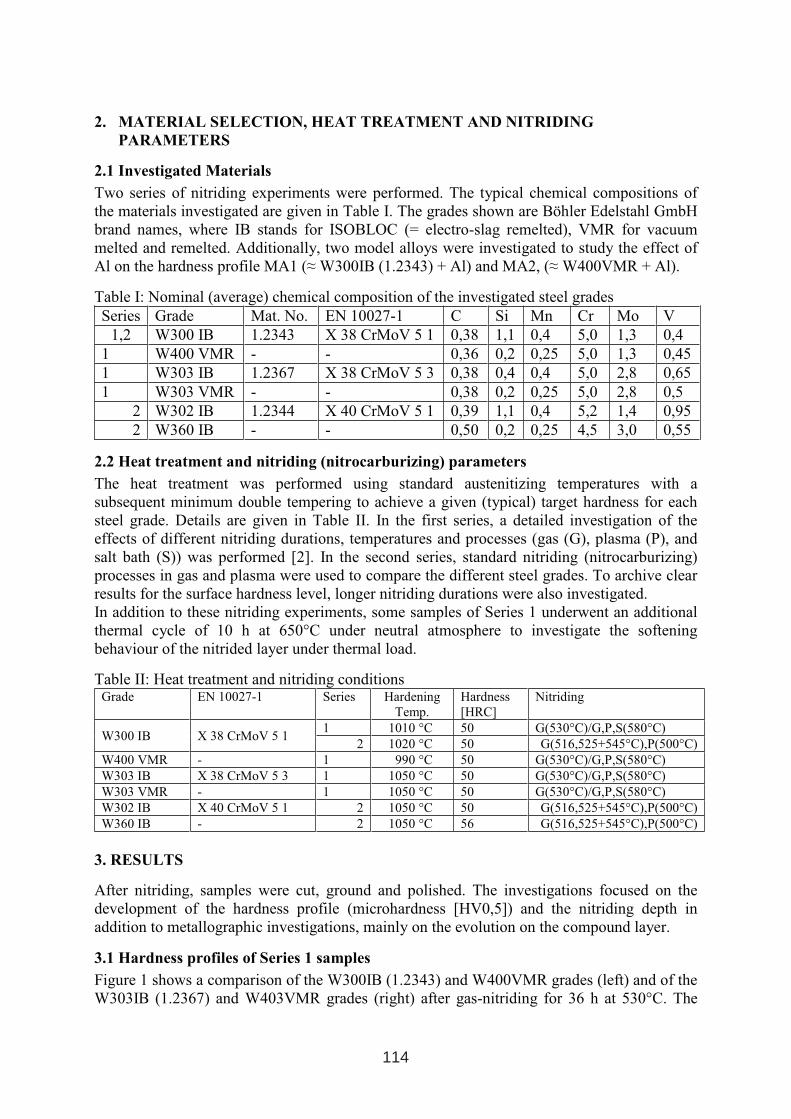
Two series of nitriding experiments were performed. The typical chemical compositions of
the materials investigated are given in Table I. The grades shown are Böhler Edelstahl GmbH
brand names, where IB stands for ISOBLOC (= electro-slag remelted), VMR for vacuum
melted and remelted. Additionally, two model alloys were investigated to study the effect of
Al on the hardness profile MA1 (≈W300IB (1.2343) + Al) and MA2, (≈ W400VMR + Al).
Table I: Nominal (average) chemical composition of the investigated steel grades
Series Grade Mat. No. EN 10027-1 C Si Mn Cr Mo V
1,2 W300 IB 1.2343 X 38 CrMoV 5 1 0,38 1,1 0,4 5,0 1,3 0,4
1 W400 VMR - - 0,36 0,2 0,25 5,0 1,3 0,45
1 W303 IB 1.2367 X 38 CrMoV 5 3 0,38 0,4 0,4 5,0 2,8 0,65
1 W303 VMR - - 0,38 0,2 0,25 5,0 2,8 0,5
2 W302 IB 1.2344 X 40 CrMoV 5 1 0,39 1,1 0,4 5,2 1,4 0,95
2 W360 IB - - 0,50 0,2 0,25 4,5 3,0 0,55
2.2 Heat treatment and nitriding (nitrocarburizing) parameters
The heat treatment was performed using standard austenitizing temperatures with a
subsequent minimum double tempering to achieve a given (typical) target hardness for each
steel grade. Details are given in Table II. In the first series, a detailed investigation of the
effects of different nitriding durations, temperatures and processes (gas (G), plasma (P), and
salt bath (S)) was performed [2]. In the second series, standard nitriding (nitrocarburizing)
processes in gas and plasma were used to compare the different steel grades. To archive clear
results for the surface hardness level, longer nitriding durations were also investigated.
In addition to these nitriding experiments, some samples of Series 1 underwent an additional
thermal cycle of 10 h at 650°C under neutral atmosphere to investigate the softening
behaviour of the nitrided layer under thermal load.
Table II: Heat treatment and nitriding conditionsGrade EN 10027-1 Series Hardening
Temp.
Hardness
[HRC]
Nitriding
1 1010 °C 50 G(530°C)/G,P,S(580°C) W300 IB X 38 CrMoV 5 1
2 1020 °C 50 G(516,525+545°C),P(500°C)
W400 VMR - 1 990 °C 50 G(530°C)/G,P,S(580°C)
W303 IB X 38 CrMoV 5 3 1 1050 °C 50 G(530°C)/G,P,S(580°C)
W303 VMR - 1 1050 °C 50 G(530°C)/G,P,S(580°C)
W302 IB X 40 CrMoV 5 1 2 1050 °C 50 G(516,525+545°C),P(500°C)
W360 IB - 2 1050 °C 56 G(516,525+545°C),P(500°C)
3. RESULTS
After nitriding, samples were cut, ground and polished. The investigations focused on the
development of the hardness profile (microhardness [HV0,5]) and the nitriding depth in
addition to metallographic investigations, mainly on the evolution on the compound layer.
3.1 Hardness profiles of Series 1 samples
Figure 1 shows a comparison of the W300IB (1.2343) and W400VMR grades (left) and of the
W303IB (1.2367) and W403VMR grades (right) after gas-nitriding for 36 h at 530°C. The
114
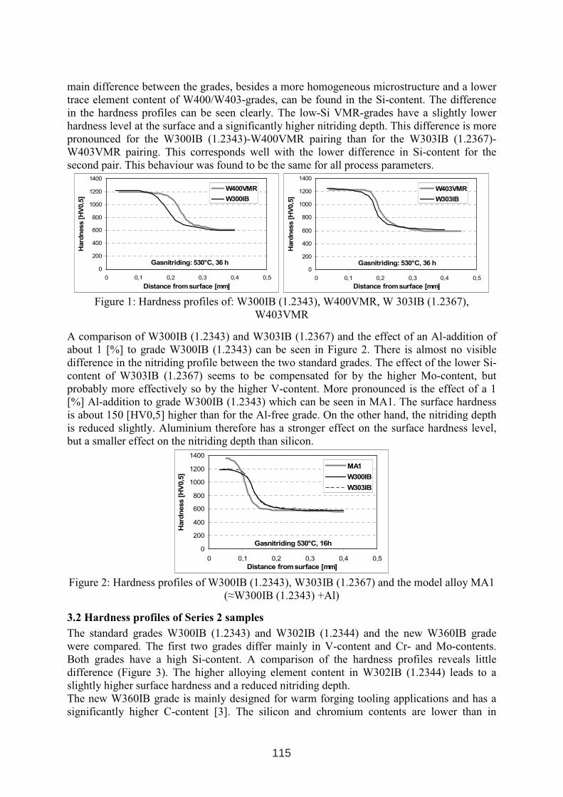
main difference between the grades, besides a more homogeneous microstructure and a lower
trace element content of W400/W403-grades, can be found in the Si-content. The difference
in the hardness profiles can be seen clearly. The low-Si VMR-grades have a slightly lower
hardness level at the surface and a significantly higher nitriding depth. This difference is more
pronounced for the W300IB (1.2343)-W400VMR pairing than for the W303IB (1.2367)-
W403VMR pairing. This corresponds well with the lower difference in Si-content for the
second pair. This behaviour was found to be the same for all process parameters.
Gasnitriding: 530°C, 36 h0
200
400
600
800
1000
1200
1400
0 0,1 0,2 0,3 0,4 0,5
Distance from surface [mm]
Hard
ness
[HV
0,5
]
W400VMR
W300IB
Gasnitriding: 530°C, 36 h0
200
400
600
800
1000
1200
1400
0 0,1 0,2 0,3 0,4 0,5
Distance from surface [mm]H
ard
ness
[HV
0,5
]
W403VMR
W303IB
Figure 1: Hardness profiles of: W300IB (1.2343), W400VMR, W 303IB (1.2367),
W403VMR
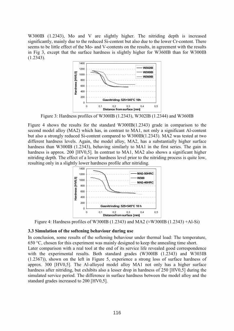
A comparison of W300IB (1.2343) and W303IB (1.2367) and the effect of an Al-addition of
about 1 [%] to grade W300IB (1.2343) can be seen in Figure 2. There is almost no visible
difference in the nitriding profile between the two standard grades. The effect of the lower Si-
content of W303IB (1.2367) seems to be compensated for by the higher Mo-content, but
probably more effectively so by the higher V-content. More pronounced is the effect of a 1
[%] Al-addition to grade W300IB (1.2343) which can be seen in MA1. The surface hardness
is about 150 [HV0,5] higher than for the Al-free grade. On the other hand, the nitriding depth
is reduced slightly. Aluminium therefore has a stronger effect on the surface hardness level,
but a smaller effect on the nitriding depth than silicon.
Gasnitriding 530°C, 16h0
200
400
600
800
1000
1200
1400
0 0,1 0,2 0,3 0,4 0,5
Distance from surface [mm]
Hard
ness
[HV
0,5
]
MA1
W300IB
W303IB
Figure 2: Hardness profiles of W300IB (1.2343), W303IB (1.2367) and the model alloy MA1
(≈W300IB (1.2343) +Al)
3.2 Hardness profiles of Series 2 samples
The standard grades W300IB (1.2343) and W302IB (1.2344) and the new W360IB grade
were compared. The first two grades differ mainly in V-content and Cr- and Mo-contents.
Both grades have a high Si-content. A comparison of the hardness profiles reveals little
difference (Figure 3). The higher alloying element content in W302IB (1.2344) leads to a
slightly higher surface hardness and a reduced nitriding depth.
The new W360IB grade is mainly designed for warm forging tooling applications and has a
significantly higher C-content [3]. The silicon and chromium contents are lower than in
115
W300IB (1.2343), Mo and V are slightly higher. The nitriding depth is increased
significantly, mainly due to the reduced Si-content but also due to the lower Cr-content. There
seems to be little effect of the Mo- and V-contents on the results, in agreement with the results
in Fig 3, except that the surface hardness is slightly higher for W360IB than for W300IB
(1.2343).
Gasnitriding: 525+545°C 10h0
200
400
600
800
1000
1200
1400
0 0,1 0,2 0,3 0,4 0,5
Distance from surface [mm]
Hard
ness
[HV
0,5
]
W302IB
W300IB
W360IB
Figure 3: Hardness profiles of W300IB (1.2343), W302IB (1.2344) and W360IB
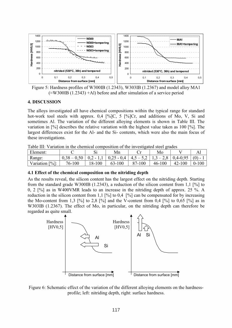
Figure 4 shows the results for the standard W300IB(1.2343) grade in comparison to the
second model alloy (MA2) which has, in contrast to MA1, not only a significant Al-content
but also a strongly reduced Si-content compared to W300IB(1.2343). MA2 was tested at two
different hardness levels. Again, the model alloy, MA2, has a substantially higher surface
hardness than W300IB (1.2343), behaving similarly to MA1 in the first series. The gain in
hardness is approx. 200 [HV0,5]. In contrast to MA1, MA2 also shows a significant higher
nitriding depth. The effect of a lower hardness level prior to the nitriding process is quite low,
resulting only in a slightly lower hardness profile after nitriding.
Gasnitrinding: 525+545°C 10 h0
200
400
600
800
1000
1200
1400
0 0,1 0,2 0,3 0,4 0,5
Distancefrom surface [mm]
Hard
ness
[HV
0,5
]
MA2-50HRC
W300
MA2-46HRC
Figure 4: Hardness profiles of W300IB (1.2343) and MA2 (≈W300IB (1.2343) +Al-Si)
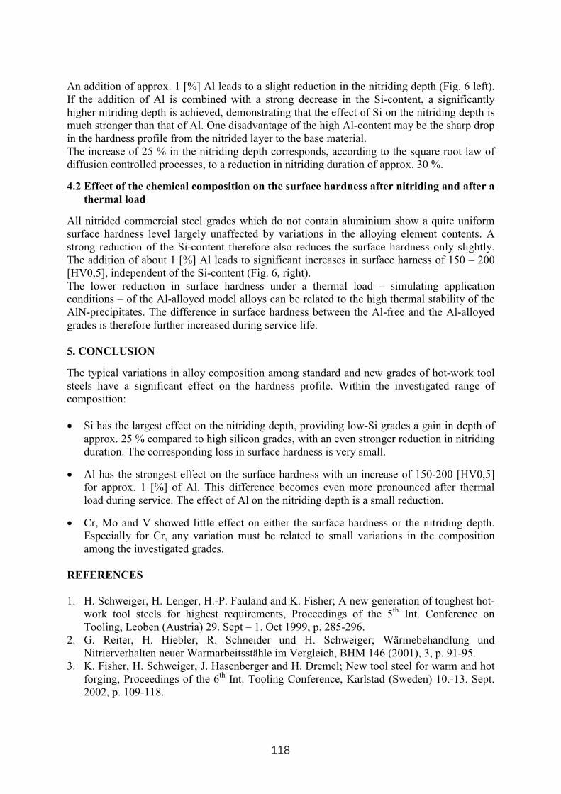
3.3 Simulation of the softening behaviour during use
In conclusion, some results of the softening behaviour under thermal load: The temperature,
650 °C, chosen for this experiment was mainly designed to keep the annealing time short.
Later comparison with a real tool at the end of its service life revealed good correspondence
with the experimental results. Both standard grades (W300IB (1.2343) and W303IB
(1.2367)), shown on the left in Figure 5, experience a strong loss of surface hardness of
approx. 300 [HV0,5]. The Al-alloyed model alloy MA1 not only has a higher surface
hardness after nitriding, but exhibits also a lesser drop in hardness of 250 [HV0,5] during the
simulated service period. The difference in surface hardness between the model alloy and the
standard grades increased to 200 [HV0,5].
116
nitrided (530°C, 36h) and tempered0
200
400
600
800
1000
1200
1400
0 0,1 0,2 0,3 0,4 0,5
Distance from surface [mm]
Hard
ness
[HV
0,5
]
W300
W300+tempering
W303
W303+tempering
nitrided (530°C, 36h) and tempered0
200
400
600
800
1000
1200
1400
0 0,1 0,2 0,3 0,4 0,5
Distance from surface [mm]
Hard
ness
[HV
0,5
]
MA1
MA1+tempering
Figure 5: Hardness profiles of W300IB (1.2343), W303IB (1.2367) and model alloy MA1
(≈W300IB (1.2343) +Al) before and after simulation of a service period
4. DISCUSSION
The alloys investigated all have chemical compositions within the typical range for standard
hot-work tool steels with approx. 0,4 [%]C, 5 [%]Cr, and additions of Mo, V, Si and
sometimes Al. The variation of the different alloying elements is shown in Table III. The
variation in [%] describes the relative variation with the highest value taken as 100 [%]. The
largest differences exist for the Al- and the Si- contents, which were also the main focus of
these investigations.
Table III: Variation in the chemical composition of the investigated steel grades
Element: C Si Mn Cr Mo V Al
Range: 0,38 – 0,50 0,2 - 1,1 0,25 - 0,4 4,5 – 5,2 1,3 – 2,8 0,4-0,95 (0) - 1
Variation [%]: 76-100 18-100 63-100 87-100 46-100 42-100 0-100
4.1 Effect of the chemical composition on the nitriding depth
As the results reveal, the silicon content has the largest effect on the nitriding depth. Starting
from the standard grade W300IB (1.2343), a reduction of the silicon content from 1,1 [%] to
0, 2 [%] as in W400VMR leads to an increase in the nitriding depth of approx. 25 %. A
reduction in the silicon content from 1,1 [%] to 0,4 [%] can be compensated for by increasing
the Mo-content from 1,3 [%] to 2,8 [%] and the V-content from 0,4 [%] to 0,65 [%] as in
W303IB (1.2367). The effect of Mo, in particular, on the nitriding depth can therefore be
regarded as quite small.
Figure 6: Schematic effect of the variation of the different alloying elements on the hardness-
profile; left: nitriding depth, right: surface hardness.
Si
SiAlAl
Distance from surface [mm] Distance from surface [mm]
Hardness
[HV0,5]
Hardness
[HV0,5]
117
An addition of approx. 1 [%] Al leads to a slight reduction in the nitriding depth (Fig. 6 left).
If the addition of Al is combined with a strong decrease in the Si-content, a significantly
higher nitriding depth is achieved, demonstrating that the effect of Si on the nitriding depth is
much stronger than that of Al. One disadvantage of the high Al-content may be the sharp drop
in the hardness profile from the nitrided layer to the base material.
The increase of 25 % in the nitriding depth corresponds, according to the square root law of
diffusion controlled processes, to a reduction in nitriding duration of approx. 30 %.
4.2 Effect of the chemical composition on the surface hardness after nitriding and after a
thermal load
All nitrided commercial steel grades which do not contain aluminium show a quite uniform
surface hardness level largely unaffected by variations in the alloying element contents. A
strong reduction of the Si-content therefore also reduces the surface hardness only slightly.
The addition of about 1 [%] Al leads to significant increases in surface harness of 150 – 200
[HV0,5], independent of the Si-content (Fig. 6, right).
The lower reduction in surface hardness under a thermal load – simulating application
conditions – of the Al-alloyed model alloys can be related to the high thermal stability of the
AlN-precipitates. The difference in surface hardness between the Al-free and the Al-alloyed
grades is therefore further increased during service life.
5. CONCLUSION
The typical variations in alloy composition among standard and new grades of hot-work tool
steels have a significant effect on the hardness profile. Within the investigated range of
composition:
• Si has the largest effect on the nitriding depth, providing low-Si grades a gain in depth of
approx. 25 % compared to high silicon grades, with an even stronger reduction in nitriding
duration. The corresponding loss in surface hardness is very small.
• Al has the strongest effect on the surface hardness with an increase of 150-200 [HV0,5]
for approx. 1 [%] of Al. This difference becomes even more pronounced after thermal
load during service. The effect of Al on the nitriding depth is a small reduction.
• Cr, Mo and V showed little effect on either the surface hardness or the nitriding depth.
Especially for Cr, any variation must be related to small variations in the composition
among the investigated grades.
REFERENCES
1. H. Schweiger, H. Lenger, H.-P. Fauland and K. Fisher; A new generation of toughest hot-
work tool steels for highest requirements, Proceedings of the 5th
Int. Conference on
Tooling, Leoben (Austria) 29. Sept – 1. Oct 1999, p. 285-296.
2. G. Reiter, H. Hiebler, R. Schneider und H. Schweiger; Wärmebehandlung und
Nitrierverhalten neuer Warmarbeitsstähle im Vergleich, BHM 146 (2001), 3, p. 91-95.
3. K. Fisher, H. Schweiger, J. Hasenberger and H. Dremel; New tool steel for warm and hot
forging, Proceedings of the 6th
Int. Tooling Conference, Karlstad (Sweden) 10.-13. Sept.
2002, p. 109-118.
118
STUDY ON CORROSION OF CHROMIUM NITRIDE AND TITANIUM NITRIDE COATINGS IN LIQUID ALUMINIUM
G. Negrea, H. Vermesan, V. Rus Faculty of Materials Science and Engineering, Technical University of Cluj-Napoca,
Muncii Avenue No. 103-105, 400641 Cluj-Napoca, Romania
ABSTRACT The corrosion produced by liquid metals can lead to severe surface degradation of tools and other components used in the die casting processes. Through surface modification and/or coating, such corrosion problems can be diminished. This paper reports on corrosion behavior in liquid aluminum of chromium nitride and titanium nitride coatings deposited by reactive sputtering on H21 tool steel samples. Monolayer and multilayer coating architectures with a thickness of 2.9-3.3 µm have been used in this study. The samples were immersed in liquid aluminum at 700 oC for 30 to 240 minutes and then, the damage produced to their surface was evaluated by eye inspection and optical microscopy. As a general observation, compared to the uncoated samples, both chromium nitride and titanium nitride coatings showed much lower tendency to interact with liquid aluminum. However, even after short immersion time, certain samples showed localized corrosion spots. The pores and other structural defects in the coating allow the penetration of aluminum through the coating, followed by its reaction with the substrate. Diffusion of aluminum into the substrate leads to a local volume expansion which generates cracking and detachment of the coatings around the defects. The study showed that corrosion resistance of tool steels in liquid aluminum can be significantly improved by chromium nitride and titanium nitride coating, but this requires deposition conditionssuch as to assure pore-free, continous coatings.
Key words: corrosion, coatings, chromium nitride, titanium nitride
1. INTRODUCTION The service life of tools and machine parts is mainly related to their ability to resist to wear, corrosion and surface fatigue. While surface modification methods such ascase hardening, carburizing, nitriding and others are primarily used to improve the wear behaviour of metallic materials, coatings can impart both wear and corrosion resistance to an engineering component. In die casting, any form of damage of the die surface affects directly the surface quality and the dimensional precision of the castings. In the case of aluminum casting, the wear produced to the die is caused, to the largest measure, by chemical
1 INTERNATIONAL CONFERENCE ON HEAT TREATMENT
AND SURFACE ENGINEERING OF TOOLS AND DIES
st
Pula, Croatia 08 - 11 June, 2005,
IFHTSE 2005
119
corrosion and physical errosion [1]. For other components of the die casting equipment such as those used for handling of the molten aluminum, the corrosion produced by the chemical interaction with the liquid metal is the main cause of failure. Since these components are usually made of alloy steel, proper surface engineering of their surfaces is needed in order to improve their durability in contact with molten aluminum. Traditionally, an economic way to increase the corrosion resistance of steel components has been the use of protective coatings obtained by chemical or electrochemical methods. However, the increasing demand for higher performance coatings, on one hand, and stronger restrictions regarding the use of polluting technologies, such as electroplating, on the other hand, have led to the development of ceramic coatings prepared by vapor deposition methods (PVD or CVD). The most frequently used coatings are nitrides, carbides and borides of transition metals and certain oxides [2,3]. These materials are usually very hard, have high chemical stability and high temperature resistance. The reports in the literature show that even in the case of very stable oxides such as Al2O3 and ZrO2 the coatings, especially PVD coatings deposited at low temperature, are prone to pitting corrosion [4]. The main reason for poor corrosion resistance of PVD coatings is due to their tendency to form columnar microstructure with many voids, pores and grain boundary defects [4]. Therefore, the exposure of such coatings to aggressive environments requires much precaution. It is also true, that the microstructure of PVD coatings deposited at low temperature can be controlled, to a certain extent, by proper adjustment of deposition parameters. It has been reported [5-7] that an intensive ion bombardment during coating growth is a viable alternative to the increase of substrate temperature for deposition of fully dense coatings. This paper presents some experimental results concerning the behaviour of chromium nitride and titanium nitride coatings in molten aluminum. The aim of the work was to evaluate the durability of the coatings in molten aluminum and to relate it to the coating material and deposition conditions (especially, ion bombardment). The mechanism of the corrosion is also discussed. The results of the present work have relevance for dies and handling components used in casting of aluminium alloys. The use of protective ceramic coatings in these applications is suggested by their high chemical stability up to high temperatures.
2. EXPERIMENTAL PROCEDURE
The samples were cut to 4x15x20 mm from H21 tool steel bar (0,35% C, 3,5% Cr, 9% W), quenched in oil from 1120 oC, double tempered at 550 oC for 2 hours and then ground and polished to achieve a roughness of about 0,1 µm. Three coating types were deposited on one side of the samples by magnetron reactive sputter deposition [6,7], chromium nitride (CrN), titanium nitride (TiN) and a multilayer consisting of five CrN2/CrN evenly stacked layers. The total thicknes of the coatingsvaried in the range 2.9-3.3 µm. Prior deposition, the substrates were in situ sputter cleaned in Ar for five minutes.
The substrate temperature at the end of deposition did not exceed 250 oC. Table I presents the coatings used in the present work. The ion bombardment during deposition was defined by two parameters ion-to-metal arriving rate ratio (Ji/JMe) and
bias voltage (Vb).
120
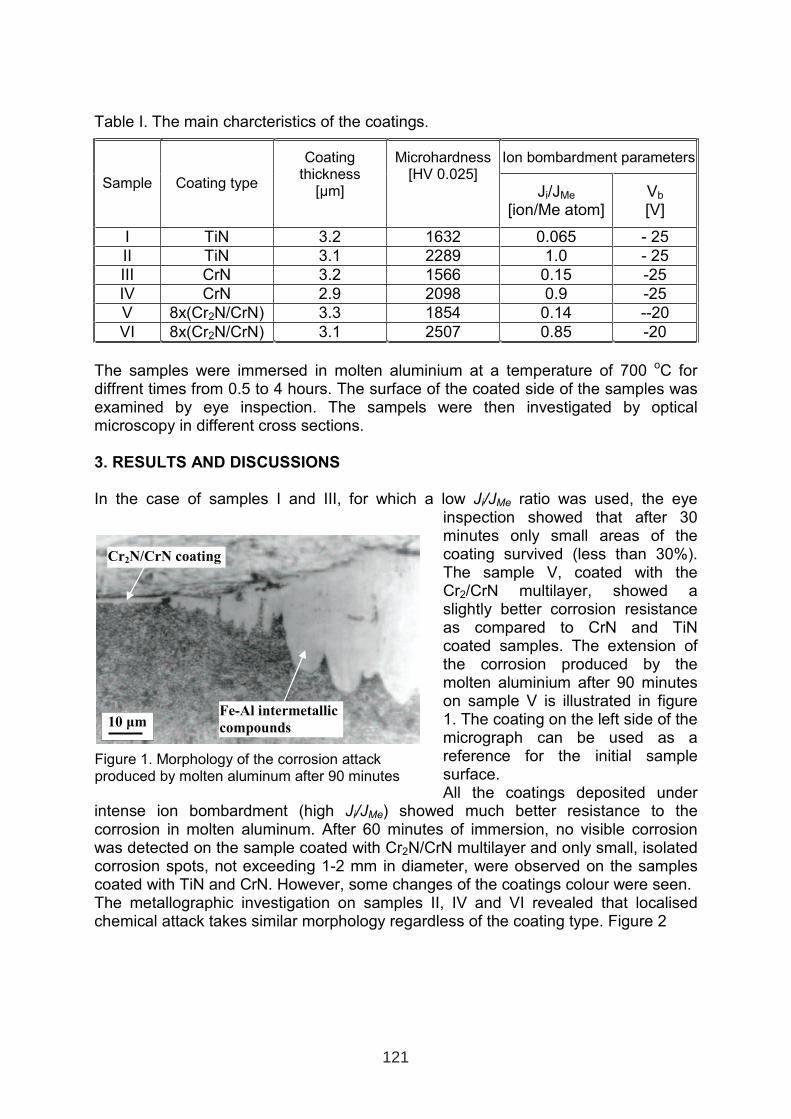
Table I. The main charcteristics of the coatings.
Ion bombardment parameters
Sample Coating type
Coating thickness
[µm]
Microhardness[HV 0.025]
Ji/JMe
[ion/Me atom]Vb
[V]
I TiN 3.2 1632 0.065 - 25
II TiN 3.1 2289 1.0 - 25
III CrN 3.2 1566 0.15 -25
IV CrN 2.9 2098 0.9 -25
V 8x(Cr2N/CrN) 3.3 1854 0.14 --20
VI 8x(Cr2N/CrN) 3.1 2507 0.85 -20
The samples were immersed in molten aluminium at a temperature of 700 oC for diffrent times from 0.5 to 4 hours. The surface of the coated side of the samples wasexamined by eye inspection. The sampels were then investigated by optical microscopy in different cross sections.
3. RESULTS AND DISCUSSIONS
In the case of samples I and III, for which a low Ji/JMe ratio was used, the eye
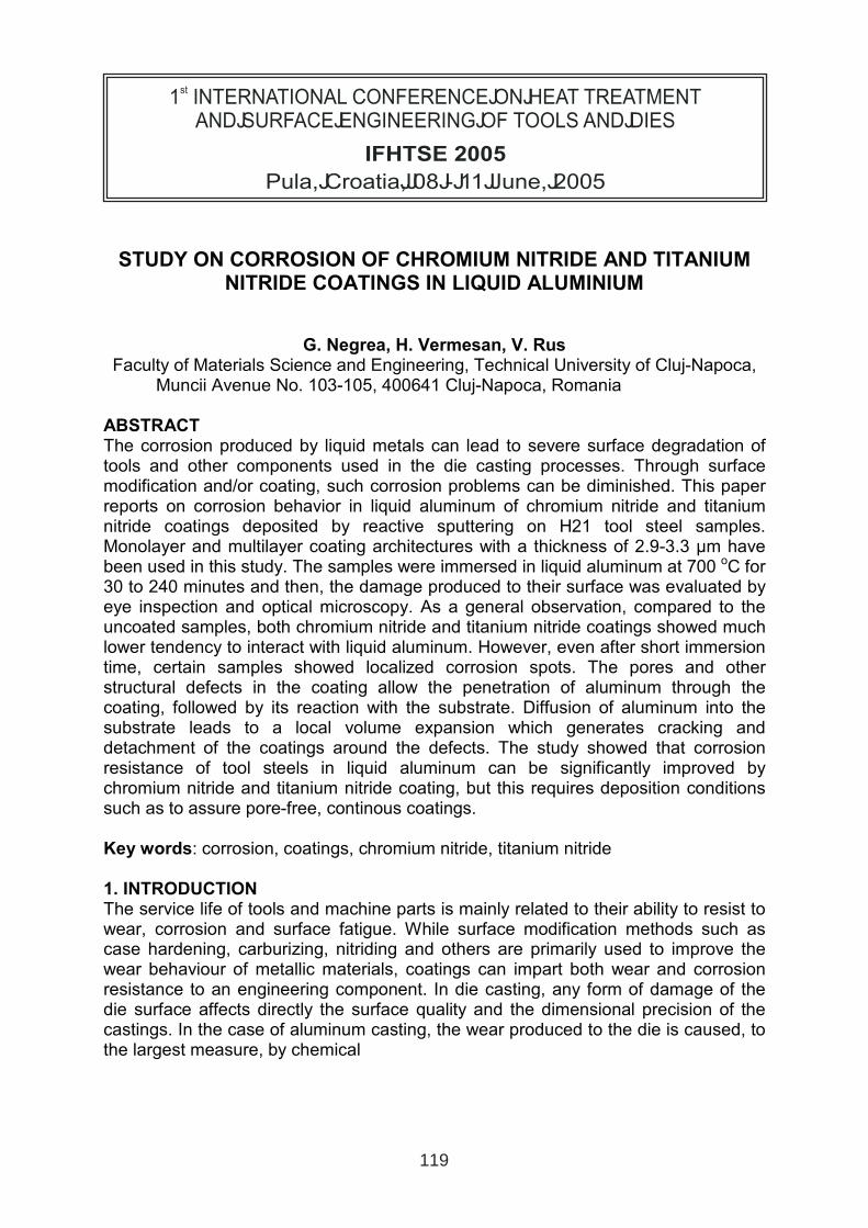
inspection showed that after 30 minutes only small areas of the coating survived (less than 30%). The sample V, coated with the Cr2/CrN multilayer, showed a slightly better corrosion resistance as compared to CrN and TiN coated samples. The extension of the corrosion produced by the molten aluminium after 90 minutes on sample V is illustrated in figure 1. The coating on the left side of the micrograph can be used as a reference for the initial sample surface. All the coatings deposited under
intense ion bombardment (high Ji/JMe) showed much better resistance to the
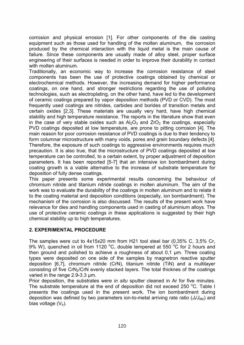
corrosion in molten aluminum. After 60 minutes of immersion, no visible corrosion was detected on the sample coated with Cr2N/CrN multilayer and only small, isolated corrosion spots, not exceeding 1-2 mm in diameter, were observed on the samples coated with TiN and CrN. However, some changes of the coatings colour were seen. The metallographic investigation on samples II, IV and VI revealed that localised chemical attack takes similar morphology regardless of the coating type. Figure 2
Figure 1. Morphology of the corrosion attackproduced by molten aluminum after 90 minutes
Fe-Al intermetallic
compounds 10 µm
Cr2N/CrN coating
121
shows a typical corrosion spot in its incipient phase. Based on the observation of a number of such corrosion pits, it was concluded that corrosion is produced by molten aluminium which penetrates through the pores or other coating defects toward the substrate. Here, aluminium reacts with the iron to form Fe-Al intermetallic compounds. The formation of these compounds generates a volume growth causing the cracking and spalling of the coating around the pore, which favours the further afflux of aluminium, intensifying the
corrosion. Figure 3 shows schematically the deterioration of the coatings due to corrosion produced by molten aluminium through this mechanism.
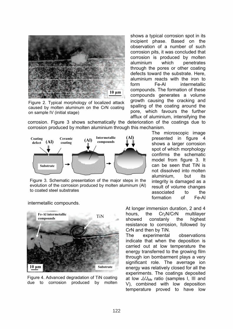
The microscopic image presented in figure 4 shows a larger corrosion spot of which morphologyconfirms the schematicmodel from figure 3. It can be seen that TiN isnot dissolved into molten aluminium, but itsintegrity is damaged as a result of volume changesassociated to the formation of Fe-Al
intermetallic compounds. At longer immersion duration, 2 and 4 hours, the Cr2N/CrN multilayer showed constanly the highest resistance to corrosion, followed by CrN and then by TiN. The experimental observations indicate that when the deposition is carried out at low temperature the energy transferred to the growing film through ion bombarment plays a verysignificant role. The averrage ion energy was relatively closed for all the experiments. The coatings deposited at low Ji/JMe ratio (samples I, III and
V), combined with low deposition temperature proved to have low
Figure 2. Typical morphology of localized attackcaused by molten aluminum on the CrN coating on sample IV (initial stage)
10 µm
Figure 4. Advanced degradation of TiN coating due to corrosion produced by molten
Fe-Al intermetallic
compounds TiN
Substrate 10 µm
(Al)(Al)
(Al)
Figure 3. Schematic presentation of the major steps in the evolution of the corrosion produced by molten aluminum (Al) to coated steel substrates
Coating
defect
Substrate
Ceramic
coating
Intermetallic
compounds
122
durability in molten aluminum due to the presence of pores or other defectes in the coating. On the other hand, the coatings deposited at high Ji/JMe ratio (samples II, IV
and VI) showed high resistance to the chemical corrosion produced by molten aluminum. The energy transferred to the growing film by ion bombardment stimulated the surface mobility of the condensed species and allowed for deposition of low defects coatings.
4. CONCLUSIONS
From the investigations on degradation of CrN, TiN and 8x(Cr2N/CN) coatings in molten aluminum, the following conclusions can be drawn: (i) All the coatings used in this study pose very low tendency to interact with molten
aluminium. The dissolution of these compounds in molten aluminium after 4 h of immersion is minor.
(ii) The coatings deposited under intense low ion bombardment (low Ji/JMe ratio)
due to the presence of microstructural defects, such as voids, pores, grain boundary defects etc., favours the localised chemical attack caused by molten aluminium. By using an intense ion bombardment during coating growth (high Ji/JMe ratio), especially in the case of multilayer structure, the “permeability” of the
coating is reduced and the corrosion can be avoided. (iii) The durability of chromium nitride seems to be superior to the durability of
titanium nitride in molten aluminum. Multilayer architecture has better resistance to corrosion as compared to single layers.
(iv) The mechanism of metallic corrosion of PVD coatings involve the following steps: (i) infiltration of aluminium through the pores or other defects present in the coating; (ii) diffusion of Al into the substrate; (iii) reaction between aluminium and substrate with formation of intermetallic compounds causing a local volume growth changes; (iv) cracking and spalling of the coating around the local defect which favours a further afflux of aluminium; (v) accelerated deterioration of the coating.
(v) Defects free chromium nitride and titanium nitride coatings can be used as protective coatings for dies and ather components in aluminum die casting applications.
References
1. M. Yan, Z. Fan, Journal of Materials Science, vol. 36 (2001), p. 285. 2. H. Holleck, Journal of Vacuum Science and Technology A, vol. 4, nr. 6 (1986), p. 2661. 3. W.D. Sproul, Journal of Vacuum Science and Technology, A, vol. 12, (1994), p. 1595. 4. A.S. Korhonen, Vacuum, vol. 45 (1994), p. 1031. 5. S.J. Bull, Vacuum, vol. 43 (1992), p. 387. 6. G. Negrea, Research concerning the preparation of some hard coatings by deposition
from vapour phase, Doctoral Thesis, Technical University of Cluj-Napoca, 1999. 7. G. Negrea, S.L. Rohde, M.L. Kuruppu, G. Vermeşan, Second International Conference on
Materials and Manufacturing Technologies, MATEHN '98, 10-13 Sept. 1998, Cluj-Napoca, Romania, Proceedings, p.805.
123

NITRIDED IRON ALUMINDE - A NEW MATERIAL FOR HOT WORKING TOOLS
A. Fischer1, H.-J. Spies
1, H. Biermann
1, M. Staia²
1Department of Materials Engineering, Technische Universität Bergakademie Freiberg,
09599 Freiberg/ Germany
² Escuela de los Materiales, Faculdad de Ingenieria, Universidad Central de Venezuela, 1042
– A Caracas/ Venezuela
Abstract
An intermetallic FeAl alloy has been gas nitrided in order to evaluate the tribological
behaviour at 25 °C and in particular at elevated temperatures, 300 °C and 600 °C. The wear
tests were carried out in air without lubrication by means of the ball-on-disk test configuration
using both alumina and tungsten–carbide balls as counterparts. The characterisation of the
worn surface was carried out using scanning electron microscopy, glow discharge optical
spectroscopy, stylus profilometry and X-ray analysis. The wear resistance of nitrided FeAl
increased more than 4 orders of magnitude at 25 °C and 2 orders of magnitude at 600 °C
compared to non–nitrided FeAl. The main wear mechanisms operating were proved to be
tribochemical processes, abrasion and surface– crushing.
Keywords: iron-based intermetallic; FeAl; nitriding; AlN; sliding wear resistance
1 INTERNATIONAL CONFERENCE ON HEAT TREATMENT
AND SURFACE ENGINEERING OF TOOLS AND DIES
st
Pula, Croatia 08 - 11 June, 2005,
IFHTSE 2005
125
1. INTRODUCTION
Hot working tools are set out to complex cyclic, mechanical and thermal loads. High load
speeds, which can lead to great temporal differences in load–intensity, are characteristic.
Additionally, corrosion processes occur due to high–temperature oxidation. The two reasons,
which mainly lead to the failure of such hot working tools, are thermal fatigue and wear,
respectively. Therefore, the requirements on the material are both sufficiently high yield
strength and high hardness at elevated temperatures. Iron aluminides are known for their
outstanding creep resistance [1]. There ability of a high strength even at elevated temperatures
benefits this material for possible high temperature applications. Nevertheless, their
tribological potential is relatively poor due to the insufficient surface hardness [2]. The strong
effect of Al on the nitridability of steels is already known. Due to this a suitable
thermochemical treatment e.g. gas nitriding should be a promising method to increase the
surface hardness of iron aluminides and meet the requirements for the high contact pressures
[3]. The present study is aiming at evaluating the tribological potential of nitrided FeAl at
ambient and in particular at elevated temperatures.
2. EXPERIMENTAL
The investigated material was an iron–based intermetallic Fe–40 at.% Al alloy with 1 wt.% of
Y2O3 particles. The nitriding treatments were carried out in an ammonia atmosphere as
reaction gas. A detailed description of the process parameters influencing the nitride layer
formation and the structure is given in a recent paper [3]. The nitriding parameters were
chosen in order to produce nitride layers of 5 µm (N5: TN = 450 °C/ tN = 3 h/ KN >2.0) and
20µm (N20: TN = 550 °C/ tN = 1 h/ KN >2.0). The characterisation of the formed nitride layer
was done by means of scanning electron microscopy (SEM), glow discharge optical
spectroscopy (GDOS), and X–ray diffraction under symmetrical θ – 2θ conditions. The
hardness was determined by Vickers hardness measurement using HV0.025. Additionally,
annealing tests were carried out on nitrided samples (N20) under decomposed ammonia
(75%H2, 25 % N2) as protection gas at 850 °C and 950 °C, respectively, to investigate the
thermal stability of the nitride layer and the bulk material.
To evaluate the tribological properties of the different nitriding conditions dry–sliding wear
tests were carried out at ambient and elevated temperatures (25 °C, 300 °C, 600 °C) using the
ball-on-disk test configuration. Selected nitrided samples (N5, N20) were tested using Al2O3-
balls, with a diameter of 6 mm, as stationary counterparts against the rotating FeAl sample.
The test parameters were 5 N normal contact load, which correspond to the Hertzian normal
contact stress of δmax=1496 MPa between alumina ball and nitrided sample, 0.1 m/s linear
sliding speed and 1000 m maximum total sliding distance. Nitrided and nitrided/oxidized
samples were tested at 25 °C. In this case tungsten carbide (WC)-balls (Ø 6 mm) were used as
tribological counterparts and the test parameters were 20 N normal contact load, which
correspond to the Hertzian normal contact stress of δmax=2696 MPa between WC-ball and
nitrided sample, 0.04 m/s linear sliding speed and 400 m total sliding distance. All tests were
carried out in air with an ambient laboratory temperature of 22 °C ± 2 °C and a relative
humidity of 50–60 %. The characterisation of the worn surface was done by means of SEM
with an energy dispersive X-ray analysis facility (EDX). Further X-ray analysis using the
glancing angle arrangement (GAXRD, Cu–Kα radiation, γ=2) gave evidence of the oxidation
occurring on the sample surface at elevated temperatures. The wear rate was determined by
calculating the wear volume on the wear track using stylus profilometry.
126
3. EVALUATION OF THE RESULTS AND DISCUSSION
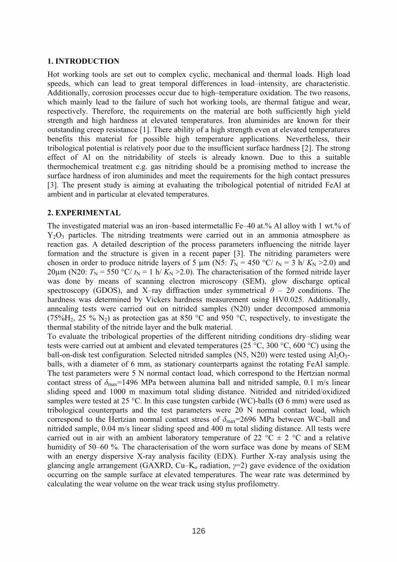
The nitriding of FeAl leads to the formation of
surface layers exhibiting hardness values in the
range of about 1400 HV0.025. The microstructure
of the nitrided FeAl shows a sharp border between
nitride layer, consisting mainly of AlN, and base
material, see Fig. 1, which is a result of the strong
interaction between the aluminium matrix and the
dissolved nitrogen. Fe atoms, which get available
due to AlN formation, form α-Fe and are
concentrated partly at grain boundaries. The
GDOS profiles, Fig. 2, show the element–
concentration–depths after the nitriding treatments
of samples N5 and N20. For both nitriding
variants the nitrogen content within the nitride
layer exceeds the amount, which is required for
the formation of AlN. This excess nitrogen is
trapped at dislocations, adsorbed at precipitate-
matrix interfaces and dissolved in the strained
ferrite matrix [3]. During the nitriding process an
external and also an internal nitriding of the α-Fe
takes place depending on the applied nitriding
parameters. An increased nitriding temperature
leads to a stronger external and internal nitriding
of Fe i.e. an increased iron nitride formation
occurs in the near surface region due to the
enhanced diffusion of Fe atoms towards the
nitrogen, which is located at the surface. This
conclusion is confirmed by Fig. 2b in which the
external nitriding reaches a depth of about 3 µm.
Results of the annealing tests, Table I, show, that
the hardness values are still at a high level after all
annealing treatments. The case hardness shows a
decrease both with increased annealing time and
with increased annealing temperature. A first
slight drop of the core hardness is measured only
after annealing at 950 °C for 11 h. During
annealing a selective inner oxidation of the AlN
occurs whereby the iron nitride above it remains
stable [3].
Nitriding of FeAl leads to a considerable
improvement of the wear resistance for all
conditions due to the increased surface hardness.
Both nitriding variants N5 and N20, respectively,
show a decreased coefficient of friction µ (COF)
and a smoother sliding movement compared to the
non–nitrided base material, Fig. 3. The determined
Fig. 1 Optical images of nitrided FeAl a) N5;
b) N20 (non–etched)
Fig. 2 GDOS profiles of nitrided FeAl
a) N5; b) N20
Table I: Influence of annealing treatments on
the hardness
Annealing
treatmentHardness HV0.025
TH (°C) tH (h) case core
1 1390 398 850
11 1240 395
1 1234 395 950
11 1080 360
127
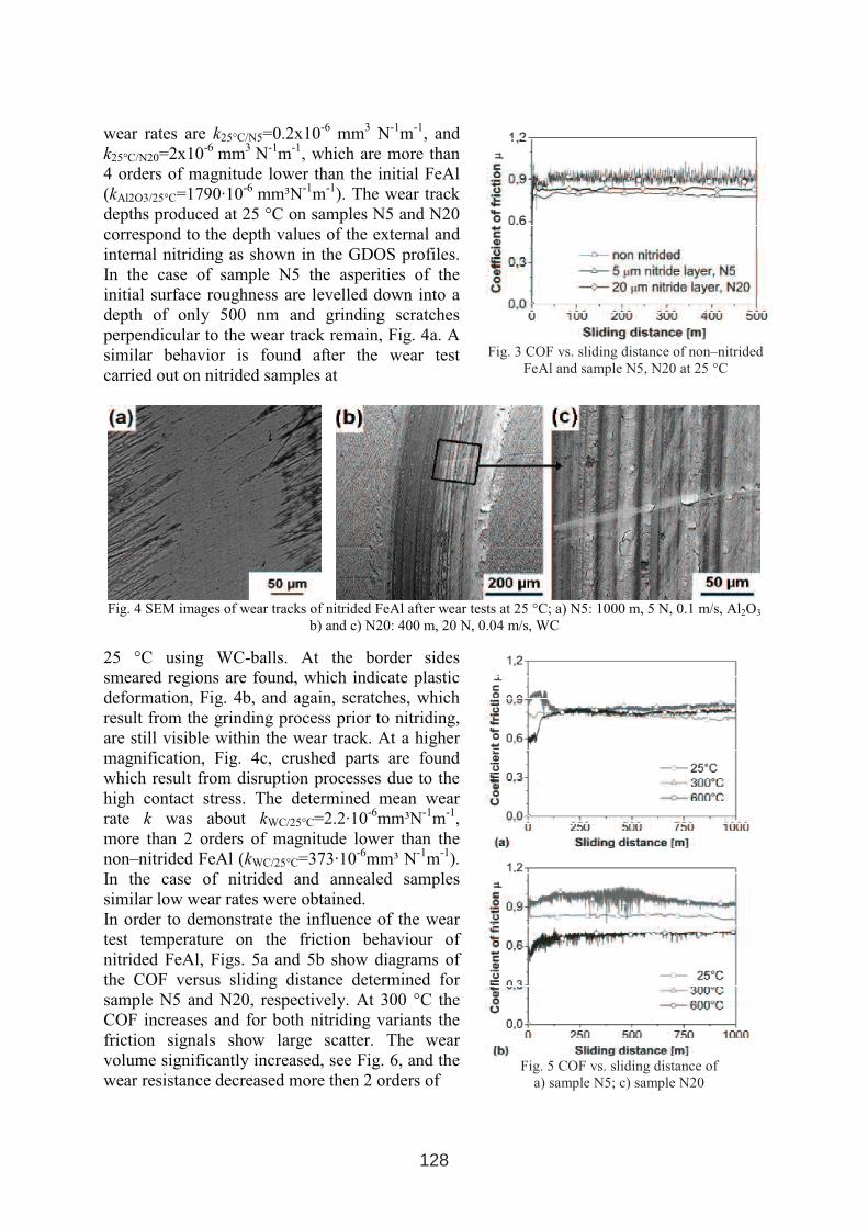
wear rates are k25°C/N5=0.2x10-6
mm3
N-1
m-1
, and
k25°C/N20=2x10-6
mm3
N-1
m-1
, which are more than
4 orders of magnitude lower than the initial FeAl
(kAl2O3/25°C=1790·10-6
mm³N-1
m-1
). The wear track
depths produced at 25 °C on samples N5 and N20
correspond to the depth values of the external and
internal nitriding as shown in the GDOS profiles.
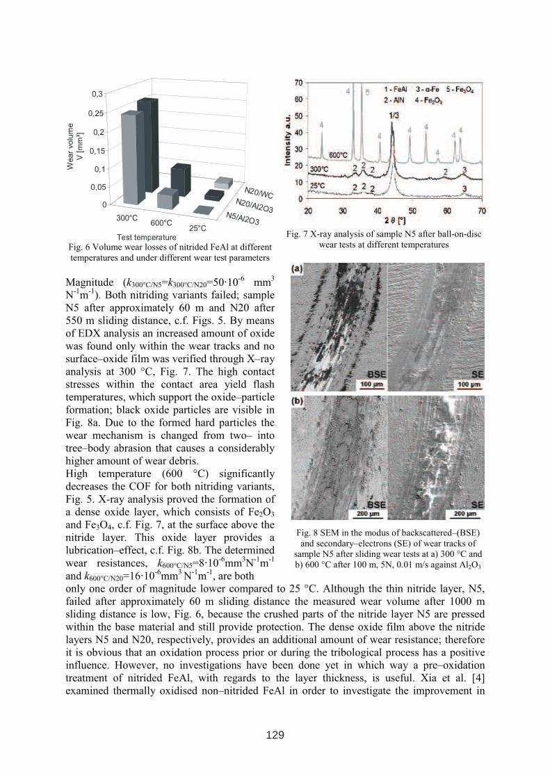
In the case of sample N5 the asperities of the
initial surface roughness are levelled down into a
depth of only 500 nm and grinding scratches
perpendicular to the wear track remain, Fig. 4a. A
similar behavior is found after the wear test
carried out on nitrided samples at
Fig. 3 COF vs. sliding distance of non–nitrided
FeAl and sample N5, N20 at 25 °C
Fig. 4 SEM images of wear tracks of nitrided FeAl after wear tests at 25 °C; a) N5: 1000 m, 5 N, 0.1 m/s, Al2O3
b) and c) N20: 400 m, 20 N, 0.04 m/s, WC
25 °C using WC-balls. At the border sides
smeared regions are found, which indicate plastic
deformation, Fig. 4b, and again, scratches, which
result from the grinding process prior to nitriding,
are still visible within the wear track. At a higher
magnification, Fig. 4c, crushed parts are found
which result from disruption processes due to the
high contact stress. The determined mean wear
rate k was about kWC/25°C=2.2·10-6
mm³N-1
m-1
,
more than 2 orders of magnitude lower than the
non–nitrided FeAl (kWC/25°C=373·10-6
mm³ N-1
m-1
).
In the case of nitrided and annealed samples
similar low wear rates were obtained.
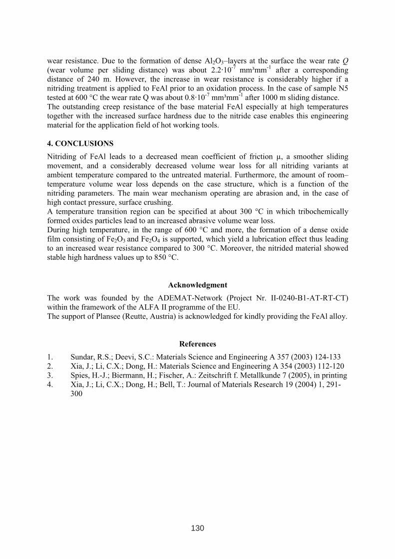
In order to demonstrate the influence of the wear
test temperature on the friction behaviour of
nitrided FeAl, Figs. 5a and 5b show diagrams of
the COF versus sliding distance determined for
sample N5 and N20, respectively. At 300 °C the
COF increases and for both nitriding variants the
friction signals show large scatter. The wear
volume significantly increased, see Fig. 6, and the
wear resistance decreased more then 2 orders ofFig. 5 COF vs. sliding distance of
a) sample N5; c) sample N20
128
300°C600°C
25°C
N5/Al2O3
N20/Al2O3
N20/WC
0
0,05
0,1
0,15
0,2
0,25
0,3
Wear
volu
me
V[m
m³]
Test temperature
Fig. 6 Volume wear losses of nitrided FeAl at different
temperatures and under different wear test parameters
Magnitude (k300°C/N5=k300°C/N20=50·10-6
mm3
N-1
m-1
). Both nitriding variants failed; sample
N5 after approximately 60 m and N20 after
550 m sliding distance, c.f. Figs. 5. By means
of EDX analysis an increased amount of oxide
was found only within the wear tracks and no
surface–oxide film was verified through X–ray
analysis at 300 °C, Fig. 7. The high contact
stresses within the contact area yield flash
temperatures, which support the oxide–particle
formation; black oxide particles are visible in
Fig. 8a. Due to the formed hard particles the
wear mechanism is changed from two– into
tree–body abrasion that causes a considerably
higher amount of wear debris.
High temperature (600 °C) significantly
decreases the COF for both nitriding variants,
Fig. 5. X-ray analysis proved the formation of
a dense oxide layer, which consists of Fe2O3
and Fe3O4, c.f. Fig. 7, at the surface above the
nitride layer. This oxide layer provides a
lubrication–effect, c.f. Fig. 8b. The determined
wear resistances, k600°C/N5=8·10-6
mm3N
-1m
-1
and k600°C/N20=16·10-6
mm3
N-1
m-1
, are both
Fig. 7 X-ray analysis of sample N5 after ball-on-disc
wear tests at different temperatures
Fig. 8 SEM in the modus of backscattered–(BSE)
and secondary–electrons (SE) of wear tracks of
sample N5 after sliding wear tests at a) 300 °C and
b) 600 °C after 100 m, 5N, 0.01 m/s against Al2O3
only one order of magnitude lower compared to 25 °C. Although the thin nitride layer, N5,
failed after approximately 60 m sliding distance the measured wear volume after 1000 m
sliding distance is low, Fig. 6, because the crushed parts of the nitride layer N5 are pressed
within the base material and still provide protection. The dense oxide film above the nitride
layers N5 and N20, respectively, provides an additional amount of wear resistance; therefore
it is obvious that an oxidation process prior or during the tribological process has a positive
influence. However, no investigations have been done yet in which way a pre–oxidation
treatment of nitrided FeAl, with regards to the layer thickness, is useful. Xia et al. [4]
examined thermally oxidised non–nitrided FeAl in order to investigate the improvement in
129
wear resistance. Due to the formation of dense Al2O3–layers at the surface the wear rate Q
(wear volume per sliding distance) was about 2.2·10-7
mm³mm-1
after a corresponding
distance of 240 m. However, the increase in wear resistance is considerably higher if a
nitriding treatment is applied to FeAl prior to an oxidation process. In the case of sample N5
tested at 600 °C the wear rate Q was about 0.8·10-7
mm³mm-1
after 1000 m sliding distance.
The outstanding creep resistance of the base material FeAl especially at high temperatures
together with the increased surface hardness due to the nitride case enables this engineering
material for the application field of hot working tools.
4. CONCLUSIONS
Nitriding of FeAl leads to a decreased mean coefficient of friction µ, a smoother sliding
movement, and a considerably decreased volume wear loss for all nitriding variants at
ambient temperature compared to the untreated material. Furthermore, the amount of room–
temperature volume wear loss depends on the case structure, which is a function of the
nitriding parameters. The main wear mechanism operating are abrasion and, in the case of
high contact pressure, surface crushing.
A temperature transition region can be specified at about 300 °C in which tribochemically
formed oxides particles lead to an increased abrasive volume wear loss.
During high temperature, in the range of 600 °C and more, the formation of a dense oxide
film consisting of Fe2O3 and Fe2O4 is supported, which yield a lubrication effect thus leading
to an increased wear resistance compared to 300 °C. Moreover, the nitrided material showed
stable high hardness values up to 850 °C.
Acknowledgment
The work was founded by the ADEMAT-Network (Project Nr. II-0240-B1-AT-RT-CT)
within the framework of the ALFA II programme of the EU.
The support of Plansee (Reutte, Austria) is acknowledged for kindly providing the FeAl alloy.
References
1. Sundar, R.S.; Deevi, S.C.: Materials Science and Engineering A 357 (2003) 124-133
2. Xia, J.; Li, C.X.; Dong, H.: Materials Science and Engineering A 354 (2003) 112-120
3. Spies, H.-J.; Biermann, H.; Fischer, A.: Zeitschrift f. Metallkunde 7 (2005), in printing
4. Xia, J.; Li, C.X.; Dong, H.; Bell, T.: Journal of Materials Research 19 (2004) 1, 291-
300
130
THE INFLUENCE OF BIAS AND IN-SITU CLEANING ON THROUGH
CAGE (TC) OR ACTIVE SCREEN PLASMA NITRIDED (ASPN)
STEELS
P Hubbard1,2
, S J Dowey1, E D Doyle
3and D G. McCulloch
2
1Surface Technology Coatings, 382 Settlement Road, Thomastown, Victoria, 3074, Australia.
2Applied Physics, School of Applied Sciences, RMIT University, GPO Box 2476V
Melbourne, Victoria, 3001, Australia. 3
Swinburne University of Technology, John Street, Hawthorn, GPO Box 218 Hawthorn,
Victoria, 3122, Australia.
ABSTRACT
The effect of a substrate bias and pre-nitride plasma etching on the nitriding response of four
steel substrates is investigated in a two factor two level full factorial experimental design.
The steels investigated were P20 (M200, Plastic mould steel), H13 (W302, Hot work tool
steel– as received), 4140 (Pre heat treated nitriding steel) and 1020 (CS1020, Bright mild
steel). The nitriding response was determined from surface and cross-sectional hardness
measurements. Nitrogen depth profile measurements were obtained using Glow Discharge
Optical Emission Spectroscopy.
Considering the main effects, the results show that without worktable bias during the nitriding
step there is effectively little or no nitriding response in most of the materials. The pre-nitride
plasma etch did not produce a significant surface hardness response in all steels except H13,
where a prior etch substantially increased surface hardness and influenced the hardness depth
profile. The bias also significantly increased the nitrogen wt%. The plasma etch also
influenced the near surface nitrogen wt% concentrations, however the practical implications
of this require further investigation.
Keyword: Active Screen Plasma Nitriding (ASPN), Design of Experiments (DOE), Glow
Discharge Optical Emission Spectroscopy (GDOES), Surface Hardness, Cross
Sectional Hardness
1. INTRODUCTION
Recently there has been considerable interest in the Active Screen or Through Cage Plasma
Nitriding process (ASPN, TC). The claimed advantage of this method is the separation of the
plasma from the work pieces. This has many benefits including the reduction of arcing
damage to the samples [1, 2]. There are ongoing discussions as to the mechanisms for this
plasma nitriding process. Early work in the 1970’s at General Electric Company [3] and
General Motor Corporation [4] proposed two different alternatives to the active species
responsible for nitriding, however, both contributors used different alloy steels in their work.
Li, et al, proposed yet another mechanism [2]. Practical experience has also shown that steel
composition plays a large role in the nitriding response in a given process. This work uses a
1 INTERNATIONAL CONFERENCE ON HEAT TREATMENT
AND SURFACE ENGINEERING OF TOOLS AND DIES
st
Pula, Croatia 08 - 11 June, 2005,
IFHTSE 2005
131
commercially available ASPN system to investigate the nitriding response of a range of steels
in a full factorial experiment [5]. This experiment investigated the effect of base plate bias
and in-situ plasma cleaning prior to nitriding.
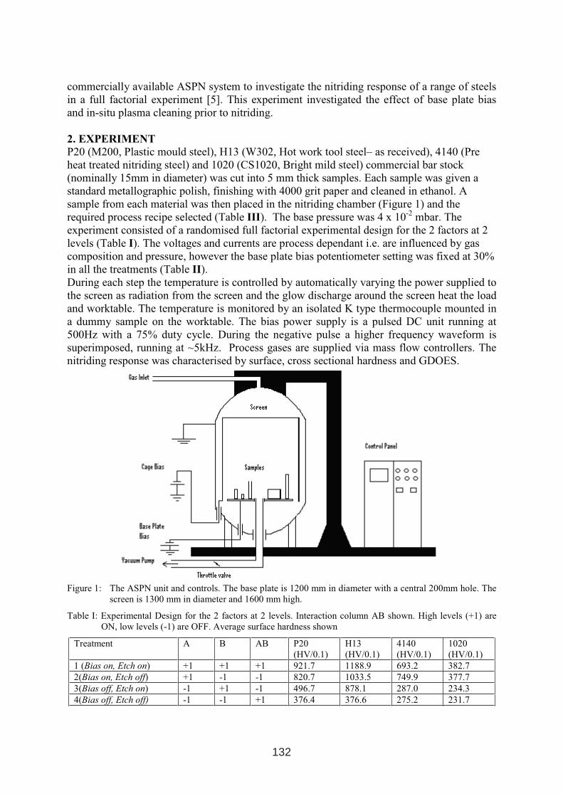
2. EXPERIMENT
P20 (M200, Plastic mould steel), H13 (W302, Hot work tool steel– as received), 4140 (Pre
heat treated nitriding steel) and 1020 (CS1020, Bright mild steel) commercial bar stock
(nominally 15mm in diameter) was cut into 5 mm thick samples. Each sample was given a
standard metallographic polish, finishing with 4000 grit paper and cleaned in ethanol. A
sample from each material was then placed in the nitriding chamber (Figure 1) and the
required process recipe selected (Table III). The base pressure was 4 x 10⁻²
mbar. The
experiment consisted of a randomised full factorial experimental design for the 2 factors at 2
levels (Table I). The voltages and currents are process dependant i.e. are influenced by gas
composition and pressure, however the base plate bias potentiometer setting was fixed at 30%
in all the treatments (Table II).
During each step the temperature is controlled by automatically varying the power supplied to
the screen as radiation from the screen and the glow discharge around the screen heat the load
and worktable. The temperature is monitored by an isolated K type thermocouple mounted in
a dummy sample on the worktable. The bias power supply is a pulsed DC unit running at
500Hz with a 75% duty cycle. During the negative pulse a higher frequency waveform is
superimposed, running at ~5kHz. Process gases are supplied via mass flow controllers. The
nitriding response was characterised by surface, cross sectional hardness and GDOES.
Figure 1: The ASPN unit and controls. The base plate is 1200 mm in diameter with a central 200mm hole. The
screen is 1300 mm in diameter and 1600 mm high.
Table I: Experimental Design for the 2 factors at 2 levels. Interaction column AB shown. High levels (+1) are
ON, low levels (-1) are OFF. Average surface hardness shown
Treatment A B AB P20
(HV/0.1)
H13
(HV/0.1)
4140
(HV/0.1)
1020
(HV/0.1)
1 (Bias on, Etch on) +1 +1 +1 921.7 1188.9 693.2 382.7
2(Bias on, Etch off) +1 -1 -1 820.7 1033.5 749.9 377.7
3(Bias off, Etch on) -1 +1 -1 496.7 878.1 287.0 234.3
4(Bias off, Etch off) -1 -1 +1 376.4 376.6 275.2 231.7
132
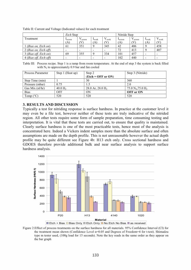
Table II: Current and Voltage (Indicated values) for each treatment
Etch Step Nitride Step
Treatment Iscreen
(A)
Vscreen
(V)
Iwork
(A)
Vwork
(V)
Iscreen
(A)
Vscreen
(V)
Iwork
(A)
Vwork
(V)
1 (Bias on, Etch on) 61 351 9 345 42 406 9 458
2 (Bias on, Etch off) - - - - 72 413 9 407
3 (Bias off, Etch on) 69 355 9 334 101 457 - -
4 (Bias off, Etch off) - - - - 102 440 - -
Table III: Process recipe. Step 1 is a ramp from room temperature. At the end of step 3 the system is back filled
with N2 to approximately 0.9 bar and fan cooled
Process Parameter Step 1 (Heat up) Step 2
(Etch = OFF or ON)
Step 3 (Nitride)
Step Time (min) 1 30 360
Pressure (mbar) 0.75 1.5 2.0
Gas Mix (nl/hr) 40.0 H2 28.0 Ar, 28.0 H2 75.0 N2,75.0 H2
Bias OFF ON OFF or ON
Temp (°C) 520 520 520
3. RESULTS AND DISCUSSION
Typically a test for nitriding response is surface hardness. In practice at the customer level it
may even be a file test, however neither of these tests are truly indicative of the nitrided
region. All other tests require some form of sample preparation, time consuming testing and
interpretation. It is vital that these tests are carried out, to ensure that quality is maintained.
Clearly surface hardness is one of the most practicable tests, hence most of the analysis is
concentrated here. Indeed a Vickers indent samples more than the absolute surface and often
assumptions are made on the depth profile. This is not unreasonable however the actual depth
profile may be quite different see Figure 4b: H13 etch only. Cross sectional hardness and
GDOES therefore provide additional bulk and near surface analysis to support surface
hardness analysis.
0
200
400
600
800
1000
1200
1400
P20 H13 4140 1020
Material
Surf
ace
Hard
ness
(HV/0
.1)
Etch + Bias Bias Only Etch Only No Etch No Bias as received
Figure 2:Effect of process treatments on the surface hardness for all materials. 95% Confidence Interval (CI) for
the treatment mean shown (Confidence Level α=0.05 and Degrees of Freedom=4 for t-test). Shimadzu
type m tester used, (100g load for 15 seconds). Note the key reads in the same order as they appear on
the bar graph
133
-300
-200
-100
0
100
200
300
P2
0A
-1
P2
0A
+1
H13
A-1
H13
A+
1
414
0A
-1
414
0A
+1
102
0A
-1
102
0A
+1
P20
B-1
P20
B+1
H1
3B
-1
H1
3B
+1
4140
B-1
4140
B+1
1020
B-1
1020
B+1
Material and Factor Level
Hard
ness
de
via
tio
n(H
V/0
.1)
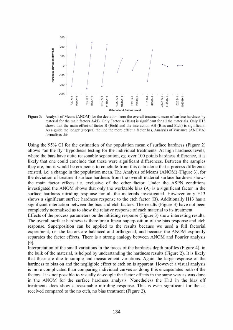
Figure 3: Analysis of Means (ANOM) for the deviation from the overall treatment mean of surface hardness by
material for the main factors A&B. Only Factor A (Bias) is significant for all the materials. Only H13
shows that the main effect of factor B (Etch) and the interaction AB (Bias and Etch) is significant.
As a guide the longer (steeper) the line the more effect a factor has, Analysis of Variance (ANOVA)
formalises this
Using the 95% CI for the estimation of the population mean of surface hardness (Figure 2)
allows ”on the fly” hypothesis testing for the individual treatments. At high hardness levels,
where the bars have quite reasonable separation, eg. over 100 points hardness difference, it is
likely that one could conclude that these were significant differences. Between the samples
they are, but it would be erroneous to conclude from this data alone that a process difference
existed, i.e. a change in the population mean. The Analysis of Means (ANOM) (Figure 3), for
the deviation of treatment surface hardness from the overall material surface hardness shows
the main factor effects i.e. exclusive of the other factor. Under the ASPN conditions
investigated the ANOM shows that only the worktable bias (A) is a significant factor in the
surface hardness nitriding response for all the materials investigated. However only H13
shows a significant surface hardness response to the etch factor (B). Additionally H13 has a
significant interaction between the bias and etch factors. The results (Figure 3) have not been
completely normalised as to show the relative response of each material to its treatment.
Effects of the process parameters on the nitriding response (Figure 3) show interesting results.
The overall surface hardness is therefore a linear superposition of the bias response and etch
response. Superposition can be applied to the results because we used a full factorial
experiment, i.e. the factors are balanced and orthogonal, and because the ANOM explicitly
separates the factor effects. There is a strong analogy between ANOM and Fourier analysis
[6].
Interpretation of the small variations in the traces of the hardness depth profiles (Figure 4), in
the bulk of the material, is helped by understanding the hardness results (Figure 2). It is likely
that these are due to sample and measurement variations. Again the large response of the
hardness to bias on and the negligible effect to etch on is apparent. However a visual analysis
is more complicated than comparing individual curves as doing this encapsulates both of the
factors. It is not possible to visually de-couple the factor effects in the same way as was done
in the ANOM for the surface hardness analysis. Nonetheless the H13 in the bias off
treatments does show a reasonable nitriding response. This is even significant for the as
received compared to the no etch, no bias treatment (Figure 2).
134
0
200
400
600
800
1000
0 50 100 150 200
Depth (microns)
HV
(0.1
)
Etch + Bias Bias Only Etch Only No Etch No Bias
a) P20
0
200
400
600
800
1000
1200
1400
0 50 100 150 200
Depth (microns)
HV
(0.1
)
Etch + Bias Bias Only Etch Only No Etch No Bias
b) H13
0
200
400
600
800
1000
0 50 100 150 200
Depth (microns)
HV
(0.1
)
Etch + Bias Bias Only Etch Only No Etch No Bias
c) 4140
0
50
100
150
200
250
300
350
400
450
0 50 100 150 200
Depth (microns)
HV
(0.1
)
Etch + Bias Bias Only Etch Only No Etch No Bias
d) 1020
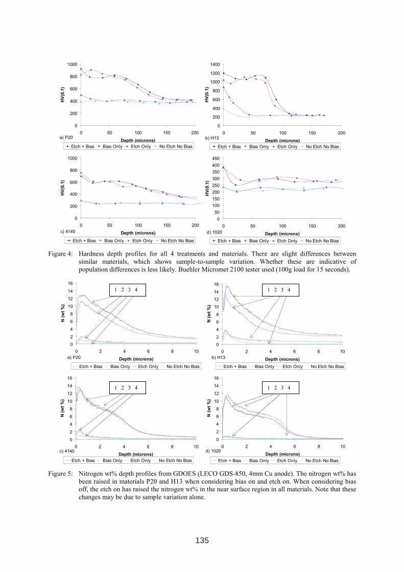
Figure 4: Hardness depth profiles for all 4 treatments and materials. There are slight differences between
similar materials, which shows sample-to-sample variation. Whether these are indicative of
population differences is less likely. Buehler Micromet 2100 tester used (100g load for 15 seconds).
0
2
4
6
8
10
12
14
16
0 2 4 6 8 10
Depth (microns)
N(w
t%
)
Etch + Bias Bias Only Etch Only No Etch No Bias
a) P20
0
2
4
6
8
10
12
14
16
0 2 4 6 8 10
Depth (microns)
N(w
t%
)
Etch + Bias Bias Only Etch Only No Etch No Bias
b) H13
0
2
4
6
8
10
12
14
16
0 2 4 6 8 10
Depth (microns)
N(w
t%
)
Etch + Bias Bias Only Etch Only No Etch No Bias
c) 4140
0
2
4
6
8
10
12
14
16
0 2 4 6 8 10
Depth (microns)
N(w
t%
)
Etch + Bias Bias Only Etch Only No Etch No Bias
d) 1020
Figure 5: Nitrogen wt% depth profiles from GDOES (LECO GDS-850, 4mm Cu anode). The nitrogen wt% has
been raised in materials P20 and H13 when considering bias on and etch on. When considering bias
off, the etch on has raised the nitrogen wt% in the near surface region in all materials. Note that these
changes may be due to sample variation alone.
1 2 3 4
1 2 3 4
1 2 3 4
1 2 3 4
135
The bias on parameter has a very large effect on the nitrogen depth profiles (Figure 5)
regardless of the etch. When the bias is off the etch on parameter has a noticeable effect on
the nitrogen depth profiles (Figure 5) especially at the near surface in comparison to the etch
off case. This is expected since this is where the etch will have the most significant effect.
This may appear to be a contradiction initially, although fundamental limitations in testing
restricts the proximity of hardness measurements close to the edge of the sample and surface
hardness testing, even at low load, is influenced by the underlying bulk. Inferences cannot be
made when making comparisons between Figure 2 and Figure 5 directly due to the horizontal
axis scale. Therefore the Nitrogen wt% concentrations require more in-depth analysis.
4. CONCLUSIONS
From the statistical analysis of the surface hardness results it can be concluded that the ASPN
process should be carried out using a bias on condition for all materials and if processing H13
an etch step would also be beneficial.
From the cross sectional hardness data (Figure 4) the need for bias during nitriding is very
clear. Without bias there is effectively little or no nitriding response. The effect of the etch
step is less noticeable except in the case of H13 when the bias is off during nitriding.
Therefore if ‘bright’ nitriding is to be done i.e. without plasma effects on the parts, only H13
and similar alloys would respond, in our process, and then only if an etch step was included.
Referring to GDOES the bias is clearly the main influence on increasing the N wt%. The etch
also influences the N wt% in the near surface region, whether this is significant and beneficial
for all the materials considered is still to be determined.
Overall, the analysis shows that bias on is essential for a satisfactory nitriding response. An
etch step is less critical although in most cases it does provide some positive effects, which
appear to be material dependent and requires further investigation especially in the near
surface region.
5. ACKNOWLEDGEMENTS
The authors would like to acknowledge H G Brinkies and J M Long for their guidance,
support and access to their facilities.
6: REFERENCES
1. J Georges: TC Plasma Nitriding: Plasma Metals, S.A, L-1817 Luxembourg, 2001.
2. C. X. Li, T. Bell, and H. Dong: Surface Engineering, 2002.
3. M Hudis: Study of ion-nitriding: Journal of Applied Physics, GEC, New York, 1972
4. G Tibbetts: Role of nitrogen atoms in “ion-nitriding”, Journal of Applied Physics, GMC,
1974.
5. G M. Clarke: Introduction to the Design and Analysis of Experiments, Arnold, 1997.
6. Madhav S Phadke: Quality Engineering Using Robust Design, Prentice Hall International
Edition, 1989.
136
INDENTATION FRACTURE TESTING OF NITRIDED LAYERS
ON H11 TOOL STEEL
D. Nolan*, V. Leskovsek, M. Jenko
* Dr Nolan is a Visiting Fellow from the University of Wollongong, Australia
Institute of Metals and Technology, Lepi Pot 11, POB 431, SI-1000, Ljubljana, Slovenia
ABSTRACT
Nitriding and nitrocarburising treatments are well accepted methods of improving the wear
performance of tool and die steels. However, our understanding of the relationship between
nitriding process parameters, microstructure and fracture behaviour of the surface layers is far
from complete. Vickers hardness indentations generate radial fractures in brittle surface
layers, and it has been shown that the length of these cracks can be used to provide valuable
information about the fracture toughness of these layers. This paper describes an investigation
of the application of indentation fracture testing to nitrided and nitrocarburized H11 hot work
tool steel. The results suggest that where a sufficiently thick compound layer has formed, this
method has the potential to be applied as a pseudo non-destructive method of monitoring the
fracture properties of treated surfaces on actual tool parts.
Keywords: Nitriding, Nitrocarburizing, Indentation fracture, Hardness testing, Palmqvist
cracks
1. INTRODUCTION
Despite the fact that nitriding and nitrocarburising treatments are well accepted methods of
improving the wear performance of tool and die steels, our understanding of the fracture
properties of these hard surfaces is far from complete. The nitride phases that arise from these
surface treatments have substantially lower fracture toughness than the underlying substrate,
and this can adversely affect the wear performance of components subjected to severe service
environments involving high shear, compressive and/or impact loading conditions. For this
reason, characterisation of the relationship between nitriding process parameters,
microstructure and fracture behaviour of the nitride layers is crucial to ensure these surface
treatments can be adopted commercially with confidence. Unfortunately, the very nature of
these relatively thin surface layers makes fracture testing by conventional means unviable.
1 INTERNATIONAL CONFERENCE ON HEAT TREATMENT
AND SURFACE ENGINEERING OF TOOLS AND DIES
st
Pula, Croatia 08 - 11 June, 2005,
IFHTSE 2005
137
One method that has the potential to fulfil this requirement involves the use of indentation
hardness testing as a pseudo non-destructive test for fracture toughness. The use of
indentation fracture testing has a numberof advantages, since it relies on a relatively
inexpensive and unsophisticated test equipment, it can be used on a wide range of sample
sizes, and it requires minimal sample preparation. However, it should be noted that although
the method is well known for analysis of relatively uniform bulk ceramic materials
[1,2,3,4,5,6], many of the assumptions made in developing the equations that relate fracture
toughness to observed cracking behaviour may not be entirely valid for materials where a thin
brittle layer is supported by a relatively tough substrate material with varying properties by
depth. Despite this, the theory and application of the method for fracture toughness testing of
thin, hard coatings has more recently been considered [7,8,9,10,11].
There are two basic cracking modes possible from Vickers indentations on brittle materials,
the radial-median and Palmqvist cracking modes. The radial-median mode derives from sub-
surface median cracks that initiate along the edges of the pyramidal indentation and extend
deep into the material in a semi-circular manner perpendicular to the surface (hence the term
"halfpenny-shaped" cracking). The Palmqvist crack morphology is characterized by much
shallower cracks emanating from the corners of the Vickers indentation. It would seem
reasonable to assume that for relatively thin brittle films on relatively tough substrates, such is
the case for a nitrided tool steel, then it would be more appropriate to use the relationships
based on the Palmqvist crack morphology, as this model is based on cracking initiating at the
surface where the material is more brittle, rather than at depth, possibly beyond the extent of
the compound layer in a nitrided sample. Indeed, the work on characterization of fracture
toughness of Ni-P films deposited on tool steel by Bozzini et al [7] used the simplified
relationship developed by Shetty et al [3] which is valid for the Palmqvist crack mode;
=
21
0319.0al
PK Ic
(1)
where P is the indentation load, a is the mean diagonal half length and l is the mean crack
length. Note that KIc is assumed to be equivalent to Kc, the critical stress intensity for cracking
in the Vickers indentation tests. Later work by Boniardi et al [8] claims to have successfully
applied the indentation fracture method to determine crack-arrest fracture toughness of
nitrided surface layers on case hardened Cr-Mo steels. However, it would appear that the
calculations for KIc contained therein used an equation that was developed by Evans et al [12]
for materials exhibiting the radial–median crack mode. Further, the relationships used by
other workers [10,11] to define fracture toughness of hard brittle films on metallic substrates
are based on equations that are valid for radial-median cracking modes. It has been suggested
that, strictly speaking, the above equations will give an estimate of the crack arrest fracture
toughness, KIa, rather than KIc [7]. However, the bulk of the literature does not discriminate in
this way, and so KIc will be used in the present work. According to the Palmqvist theory,
fracture toughness KIc should be independent of the applied load. The most valid measure of
KIc for the thin coating can therefore be obtained by extrapolating the KIc versus P data to
P=0, where the intrinsic fracture toughness of the coating, denoted by KIc0 , can be derived.
The fracture indentation method offers numerous potential benefits in terms of
characterization of the mechanical properties of hard, thin coatings in industrial environments.
138
However, there are inconsistencies in the way that this method has been applied in previous
work. The current work was undertaken to investigate the application of the indentation
fracture test method to nitrided and nitrocarburized surface layers on H11 tool steel. The
objective is to determine whether Equation 1 above (for Palmqvist cracking mode) can be
used to give a valid and reliable measure of fracture toughness of nitrided compound layers on
nitrided H11 tool steel.
2. EXPERIMENTAL MATERIALS AND METHODS
The tool steel investigated was ESR AISI H11, with nominal composition 0.38 %C, 5 %Cr,
1.3%Mo, 0.4 %V. The steel was heat treated in a horizontal vacuum furnace with uniform
high-pressure gas-quenching using nitrogen (N2) at a pressure of 1.05 bars. The specimens
were heated at 10°C/min to the austenitizing temperature of 1020 °C, soaked for 30 minutes,
gas quenched to a temperature of 100 °C, and then double tempered. The first temper was
performed at 540 °C for 4 hours and the second at 585 °C for 4 hours. The specimens were
then plasma nitrided at 480 °C (sample A) or 540 °C (sample B), or nitrocarburized at 580 °C
(sample C), using 300 hPa pressure and a total gas flow rate of 75 l/h. The gas atmosphere
was 25 %N2–75 %H2 for nitriding, and 87 %N2–2 %CO2–11 %H2. Heating to process
temperature took approximately 3 hours and the treatment duration was 16 hours.
In order to facilitate accurate measurement of the dimensions of indentations and cracks, the
surface of each sample was lightly polished using 1µm diamond paste in order to provide a
mirror finish while ensuring minimal loss of compound layer thickness. The polished surfaces
were then subjected to Vickers hardness testing at loads of 5, 10, 15, 20, 30, 40, 50, 60 and
100 kg. Indent and crack dimensions were measured using an optical microscope, and the
measured values of crack and indent half-diagonal lengths were used to calculate KIc
according to Equation (1) above. A value of KIc0 is then derived by extrapolation to a zero
load condition. Samples were cut and mounted in bakelite in cross-section, and prepared
metallographically for analysis of microstructure and hardness depth profiles. Microhardness
depth profiling was conducted using a Fischerscope H100C machine at a load of 0.1N (~10g)
and hardness of near surface hardness in cross-section was measured at a load of 0.002N
(~0.2g). Microstructures were revealed by etching with 2% nital solution and compound
layers were etched with Marbles reagent.
3. RESULTS
A graph showing surface hardness as a function of indentation load is presented in Figure 1.
The nitriding treatments produced higher hardness than the nitrocarburizing treatment at
lower indentation loads. However, at higher loads the low temperature nitriding treatment
showed hardness values ~100HV lower than for the higher temperature nitriding and
nitrocarburizing treatments. In relation to the appearance of indentations and the mode of
cracking observed, sample A produced only one case of Palmqvist cracking. The predominant
mode of cracking in sample A was concentric rings, becoming apparent at 20 kg load and
becoming more extensive with increasing load. An example of such concentric cracking is
shown in Figure 2(a). Sample B showed some minor Palmqvist-type cracking at loads of 5,
10, 15, 20 and 60 kg loads. However, at 60 kg load, the concentric cracking predominant for
139
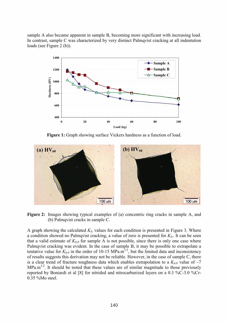
sample A also became apparent in sample B, becoming more significant with increasing load.
In contrast, sample C was characterized by very distinct Palmqvist cracking at all indentation
loads (see Figure 2 (b)).
400
600
800
1000
1200
1400
0 20 40 60 80 100
Load (kg)
Ha
rdn
ess
(HV
)
Sample A
Sample B
Sample C
Figure 1: Graph showing surface Vickers hardness as a function of load.
Figure 2: Images showing typical examples of (a) concentric ring cracks in sample A, and
(b) Palmqvist cracks in sample C.
A graph showing the calculated KIc values for each condition is presented in Figure 3. Where
a condition showed no Palmqvist cracking, a value of zero is presented for KIc. It can be seen
that a valid estimate of KIc0 for sample A is not possible, since there is only one case where
Palmqvist cracking was evident. In the case of sample B, it may be possible to extrapolate a
tentative value for KIc0 in the order of 10-15 MPa.m1/2
, but the limited data and inconsistency
of results suggests this derivation may not be reliable. However, in the case of sample C, there
is a clear trend of fracture toughness data which enables extrapolation to a KIc0 value of ~7
MPa.m1/2
. It should be noted that these values are of similar magnitude to those previously
reported by Boniardi et al [8] for nitrided and nitrocarburized layers on a 0.3 %C-3.0 %Cr-
0.35 %Mo steel.
(a) HV60 (b) HV60
140
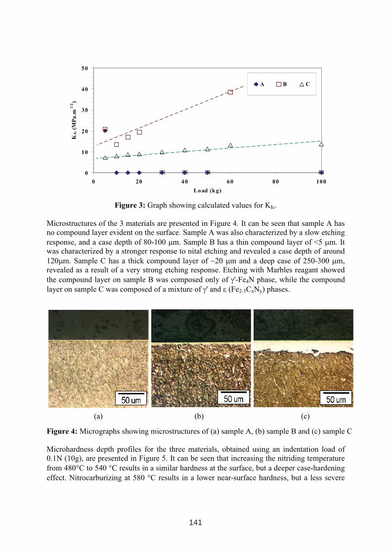
Figure 3: Graph showing calculated values for KIc.
Microstructures of the 3 materials are presented in Figure 4. It can be seen that sample A has
no compound layer evident on the surface. Sample A was also characterized by a slow etching
response, and a case depth of 80-100 µm. Sample B has a thin compound layer of <5 µm. It
was characterized by a stronger response to nital etching and revealed a case depth of around
120µm. Sample C has a thick compound layer of ~20 µm and a deep case of 250-300 µm,
revealed as a result of a very strong etching response. Etching with Marbles reagant showed
the compound layer on sample B was composed only of γ'-Fe4N phase, while the compound
layer on sample C was composed of a mixture of γ' and ε (Fe2-3CxNy) phases.
(a) (b) (c)
Figure 4: Micrographs showing microstructures of (a) sample A, (b) sample B and (c) sample C
Microhardness depth profiles for the three materials, obtained using an indentation load of
0.1N (10g), are presented in Figure 5. It can be seen that increasing the nitriding temperature
from 480°C to 540 °C results in a similar hardness at the surface, but a deeper case-hardening
effect. Nitrocarburizing at 580 °C results in a lower near-surface hardness, but a less severe
0
10
20
30
40
50
0 20 40 60 80 100
Load (kg)
KIc
(MP
a.m
1/2
)
A B C
141
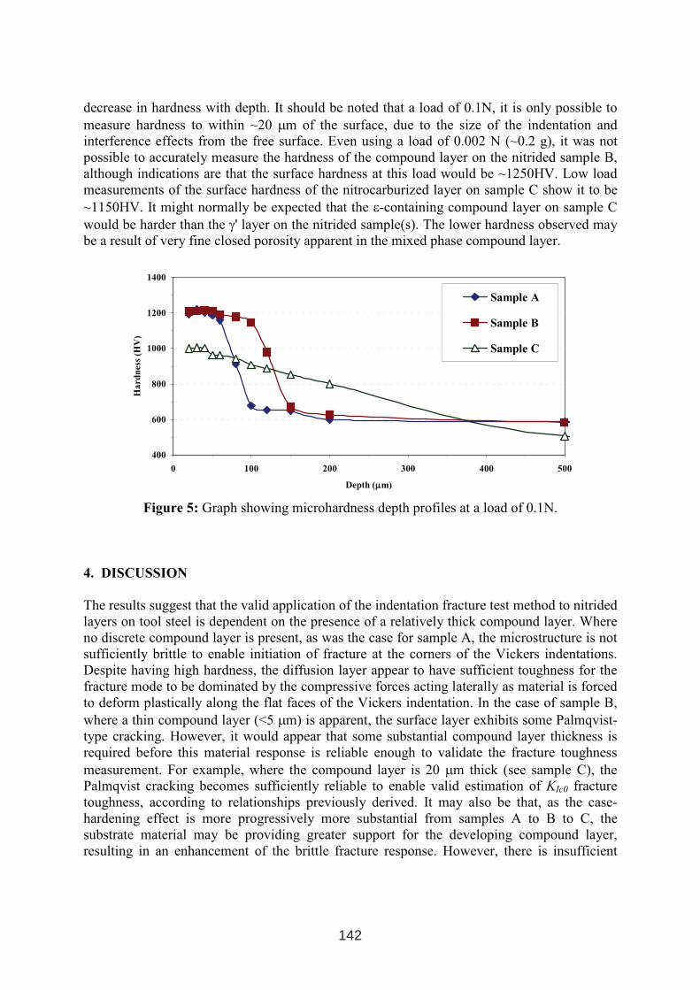
decrease in hardness with depth. It should be noted that a load of 0.1N, it is only possible to
measure hardness to within ~20 µm of the surface, due to the size of the indentation and
interference effects from the free surface. Even using a load of 0.002 N (~0.2 g), it was not
possible to accurately measure the hardness of the compound layer on the nitrided sample B,
although indications are that the surface hardness at this load would be ~1250HV. Low load
measurements of the surface hardness of the nitrocarburized layer on sample C show it to be
~1150HV. It might normally be expected that the ε-containing compound layer on sample C
would be harder than the γ' layer on the nitrided sample(s). The lower hardness observed may
be a result of very fine closed porosity apparent in the mixed phase compound layer.
400
600
800
1000
1200
1400
0 100 200 300 400 500
Depth (µµm)
Ha
rd
ness
(HV
)
Sample A
Sample B
Sample C
Figure 5: Graph showing microhardness depth profiles at a load of 0.1N.
4. DISCUSSION
The results suggest that the valid application of the indentation fracture test method to nitrided
layers on tool steel is dependent on the presence of a relatively thick compound layer. Where
no discrete compound layer is present, as was the case for sample A, the microstructure is not
sufficiently brittle to enable initiation of fracture at the corners of the Vickers indentations.
Despite having high hardness, the diffusion layer appear to have sufficient toughness for the
fracture mode to be dominated by the compressive forces acting laterally as material is forced
to deform plastically along the flat faces of the Vickers indentation. In the case of sample B,
where a thin compound layer (<5 µm) is apparent, the surface layer exhibits some Palmqvist-
type cracking. However, it would appear that some substantial compound layer thickness is
required before this material response is reliable enough to validate the fracture toughness
measurement. For example, where the compound layer is 20 µm thick (see sample C), the
Palmqvist cracking becomes sufficiently reliable to enable valid estimation of KIc0 fracture
toughness, according to relationships previously derived. It may also be that, as the case-
hardening effect is more progressively more substantial from samples A to B to C, the
substrate material may be providing greater support for the developing compound layer,
resulting in an enhancement of the brittle fracture response. However, there is insufficient
142
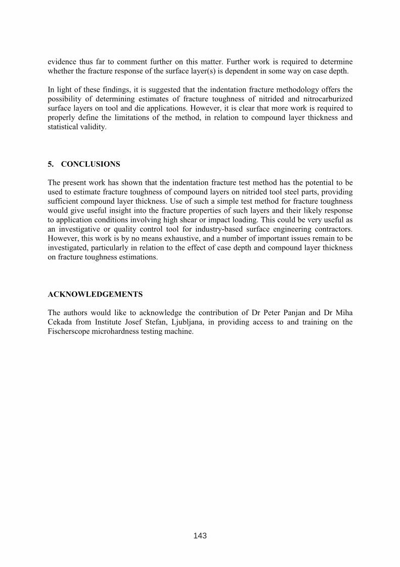
evidence thus far to comment further on this matter. Further work is required to determine
whether the fracture response of the surface layer(s) is dependent in some way on case depth.
In light of these findings, it is suggested that the indentation fracture methodology offers the
possibility of determining estimates of fracture toughness of nitrided and nitrocarburized
surface layers on tool and die applications. However, it is clear that more work is required to
properly define the limitations of the method, in relation to compound layer thickness and
statistical validity.
5. CONCLUSIONS
The present work has shown that the indentation fracture test method has the potential to be
used to estimate fracture toughness of compound layers on nitrided tool steel parts, providing
sufficient compound layer thickness. Use of such a simple test method for fracture toughness
would give useful insight into the fracture properties of such layers and their likely response
to application conditions involving high shear or impact loading. This could be very useful as
an investigative or quality control tool for industry-based surface engineering contractors.
However, this work is by no means exhaustive, and a number of important issues remain to be
investigated, particularly in relation to the effect of case depth and compound layer thickness
on fracture toughness estimations.
ACKNOWLEDGEMENTS
The authors would like to acknowledge the contribution of Dr Peter Panjan and Dr Miha
Cekada from Institute Josef Stefan, Ljubljana, in providing access to and training on the
Fischerscope microhardness testing machine.
143
REFERENCES
1. S. Palmqvist, Arch. Eisenhuttenwes., 33 (9), 1962, pp.629-634.
2. B. Lawn and R. Wilshaw, J. Mater. Sci., 10 (1975), pp.1049-1081.
3. D.K. Shetty, I.G. Wright, P.N. Mincer and A.H. Clauer, J. Mater. Sci., 20 (1985), p.1873.
4. C. Ponton and R. Rawlings, Mat. Sci. Techn., 5, October, 1989, p.865.
5. C. Ponton and R. Rawlings, Mat. Sci. Techn., 5, October, 1989, p.961.
6. M. Sakai and R. Bradt, Int. Mat.Rev., Vol.38, No.2, 1993, p.53.
7. B. Bozzini and M. Boniardi, Z. Metallk., 88 (1997), p.493
8. M. Boniardi, G.C. Martinelli and B. Bozzini, in Proc. Of the 4th ASM Heat Treatment and
Surface Engineering Conference, Florence, Italy, October, 1998, p. 361.
9. T. Bin, Z. Xiadong, H. Naisai, H Jiawen, Surface and Coating Technology, 131, 2000,
p.391.
10. W. Feng, D, Yan, J. He, G. Zhang, G. Chen, W. Gu and S. Yang, Applied Surface
Science, (2004), In Press.
11. S. Zhang, D. Sun, Y. Fu and H. Du, Surface and Coatings Technology, (2004), In press.
12. A. Evans and E. Charles, J.Am.Ceram.Soc., 59, (7-8), 1976, pp.371-372.
144
VACUUM OXYCARBONITRIDING OF ARTICLES OF X12 TOOL
STEEL
Plamen Daneva, Danail Gospodinov
a, Rozita Radeva
b
aUniversity of Rousse, Department of Material Science and Technology, 8 Studentska St.
Rousse 7017, BulgariabMagnum Industries Ltd., 83 Pliska St., Rousse 7004, Bulgaria
The paper is presenting the general results obtained during the investigation of vacuum
oxycarbonitriding process using articles made of X12 (X210Cr12 Din 17006) tool steel. The
processes have been carried out in a vacuum unit1
with a gas flow of NH3 + CO2. The thermal
conditions have not allowed the formation of a phase-boundary layer. The articles have been
quenched preliminarily to a “low hardness” (HRC 56) and tempered at 320°C. The saturation
has been carried out at 520°C for 7 hours. The phase composition, surface hardness of the
tools and the micro-hardness depth distribution have been determined. The possibility for
saturation with N, C and O for X12 tools preliminarily Cr galvanic coated has been studied as
well in order to achieve surface properties change of the durability and the wear-resistance of
the tool’s surface.
Key words: vacuum furnaces, nitriding, carbonitriding, oxycarbonitriding
1. INTRODUCTION
It is a well-known fact that the steels from the X12 (X210Cr12 DIN 17006) group have
medium heat resistance. This is a preposition concerned with some difficulties for hardness
increase obtained after chemical heat treatment at temperatures higher than 500°С. The
difficulties are due to the rapid decrease of the hardness of the unsaturated core of the steel
details at this temperature range. A possibility for heat resistance increase is the so-called
“low hardness” tempering [1]. The tools are heated to temperatures higher by 90…120°С
from the optimal. During the heating process the austenite is saturated with chrome and other
carbide-forming chemical elements (Mo, W, V) and after the cooling this austenite is turning
into “more alloyed” martensite with increased heat resistance and an alloyed residual
austenite. Both structures are willing to disintegration at higher temperatures. Because of the
higher amount of the residual austenite and the negligible quantity of carbides the average
hardness after quenching is lower (HRC 55…56).
The general aim of the investigation is to be examined the phase structure and some
characteristics of X12 articles after “low” hardness tempering and vacuum oxycarbonitriding.
The treatment is performed in order to achieve durability and wear-ability increase of the
tools especially for those working at higher temperatures, large concentrated loads and
friction. The second aim is to be determined for vacuum oxycarbonitriding the formation
possibilities for diffusion chrome-oxy-carbonitriding coating or chrome-nitriding coating over
1The whole experimental part of the investigations has been performed in the vacuum unit of the Company
“METALIKA-MIST” Rousse
1 INTERNATIONAL CONFERENCE ON HEAT TREATMENT
AND SURFACE ENGINEERING OF TOOLS AND DIES
st
Pula, Croatia 08 - 11 June, 2005,
IFHTSE 2005
145
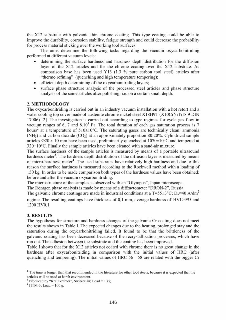
the X12 substrate with galvanic thin chrome coating. This type coating could be able to
improve the durability, corrosion stability, fatigue strength and could decrease the probability
for process material sticking over the working tool surfaces.
The aims determine the following tasks regarding the vacuum oxycarbonitriding
performed at different vacuum levels:
• determining the surface hardness and hardness depth distribution for the diffusion
layer of the X12 articles and for the chrome coating over the X12 substrate. As
comparison base has been used Y13 (1.3 % pure carbon tool steel) articles after
“thermo refining” (quenching and high temperature tempering);
• efficient depth determining of the oxycarbonitriding layers;
• surface phase structure analysis of the processed steel articles and phase structure
analysis of the same articles after polishing, i.e. on a certain small depth.
2. METHODOLOGY
The oxycarbonitriding is carried out in an industry vacuum installation with a hot retort and a
water cooling top cover made of austenite chrome-nickel steel Х18Н9Т (X10CrNiTi18 9 DIN
17006) [2]. The investigation is carried out according to type regimes for cycle gas flow in
vacuum ranges of 6, 7 and 8.104Ра. The total duration of each gas saturation process is 7
hours2
at a temperature of 510±10°С. The saturating gases are technically clean: ammonia
(NH3) and carbon dioxide (СО2) at an approximately proportion 80:20%. Cylindrical sample
articles Ø20 х 10 mm have been used, preliminarily quenched at 1070±10°С and tempered at
320±10°С. Finally the sample articles have been cleaned with a sand-air mixture.
The surface hardness of the sample articles is measured by means of a portable ultrasound
hardness meter3. The hardness depth distribution of the diffusion layer is measured by means
of micro-hardness meter4. The used substrates have relatively high hardness and due to this
reason the surface hardness is measured according to the Rockwell method with a loading of
150 kg. In order to be made comparison both types of the hardness values have been obtained:
before and after the vacuum oxycarbonitriding.
The microstructure of the samples is observed with an “Olympus”, Japan microscope.
The Röntgen phase analysis is made by means of a diffractometer “DRON-2”, Russia.
The galvanic chrome coatings are made in industrial conditions at a Т=55±3°С; Dк≈40 А/dm2
regime. The resulting coatings have thickness of 0,1 mm, average hardness of 1HV >995 and
1200 HV0,1.
3. RESULTS
The hypothesis for structure and hardness changes of the galvanic Cr coating does not meet
the results shown in Table I. The expected changes due to the heating, prolonged stay and the
saturation during the oxycarbonitriding failed. It found to be that the brittleness of the
galvanic coating has been decreased because of the recrystallization processes, which have
run out. The adhesion between the substrate and the coating has been improved.
Table I shows that for the X12 articles not coated with chrome there is no great change in the
hardness after oxycarbonitriding in comparison with the initial values of HRC (after
quenching and tempering). The initial values of HRC 56 - 58 are related with the bigger Cr
2The time is longer than that recommended in the literature for other tool steels, because it is expected that the
articles will be used at harsh environment. 3
Produced by “Krautkrämer”, Switzerlan; Load = 1 kg. 4ПТМ-3; Load = 100 g.
146
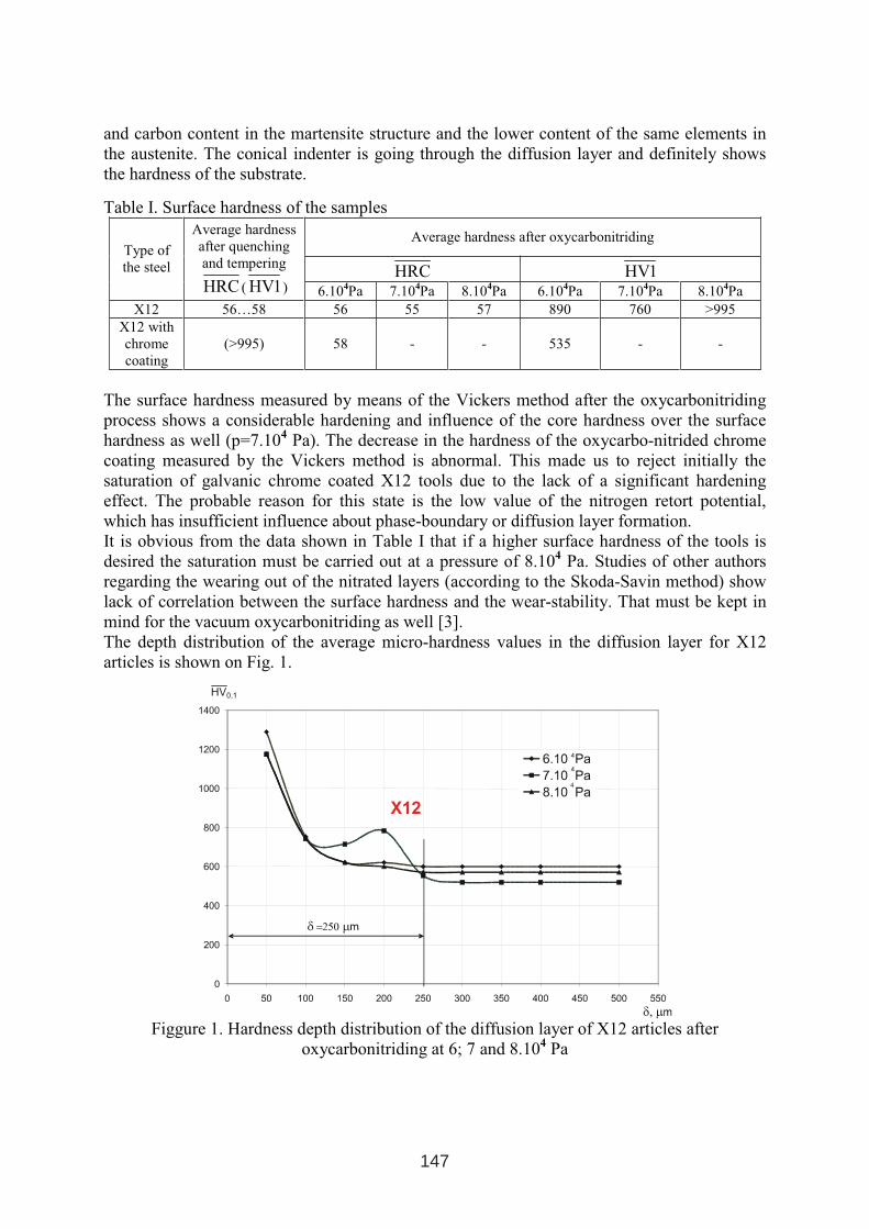
and carbon content in the martensite structure and the lower content of the same elements in
the austenite. The conical indenter is going through the diffusion layer and definitely shows
the hardness of the substrate.
Table I. Surface hardness of the samples
Average hardness after oxycarbonitriding
HRC 1HV
Type of
the steel
Average hardness
after quenching
and tempering
HRC ( 1HV ) 6.104Ра 7.10
4Ра 8.10
4Ра 6.10
4Ра 7.10
4Ра 8.10
4Ра
Х12 56…58 56 55 57 890 760 >995
Х12 with
chrome
coating
(>995) 58 - - 535 - -
The surface hardness measured by means of the Vickers method after the oxycarbonitriding
process shows a considerable hardening and influence of the core hardness over the surface
hardness as well (р=7.104Ра). The decrease in the hardness of the oxycarbo-nitrided chrome
coating measured by the Vickers method is abnormal. This made us to reject initially the
saturation of galvanic chrome coated X12 tools due to the lack of a significant hardening
effect. The probable reason for this state is the low value of the nitrogen retort potential,
which has insufficient influence about phase-boundary or diffusion layer formation.
It is obvious from the data shown in Table I that if a higher surface hardness of the tools is
desired the saturation must be carried out at a pressure of 8.104Ра. Studies of other authors
regarding the wearing out of the nitrated layers (according to the Skoda-Savin method) show
lack of correlation between the surface hardness and the wear-stability. Тhat must be kept in
mind for the vacuum oxycarbonitriding as well [3].
The depth distribution of the average micro-hardness values in the diffusion layer for X12
articles is shown on Fig. 1.
Figgure 1. Hardness depth distribution of the diffusion layer of X12 articles after
oxycarbonitriding at 6; 7 and 8.104
Pa
147
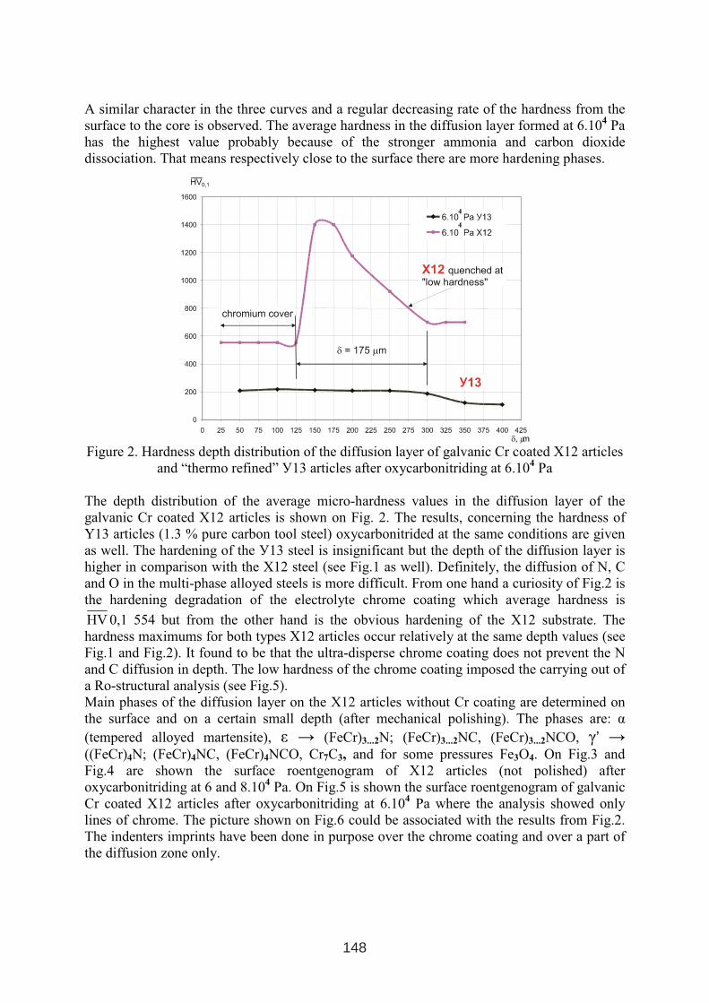
A similar character in the three curves and a regular decreasing rate of the hardness from the
surface to the core is observed. The average hardness in the diffusion layer formed at 6.104Ра
has the highest value probably because of the stronger ammonia and carbon dioxide
dissociation. That means respectively close to the surface there are more hardening phases.
Figure 2. Hardness depth distribution of the diffusion layer of galvanic Cr coated X12 articles
and “thermo refined” У13 articles after oxycarbonitriding at 6.104
Pa
The depth distribution of the average micro-hardness values in the diffusion layer of the
galvanic Cr coated X12 articles is shown on Fig. 2. The results, concerning the hardness of
Y13 articles (1.3 % pure carbon tool steel) oxycarbonitrided at the same conditions are given
as well. The hardening of the У13 steel is insignificant but the depth of the diffusion layer is
higher in comparison with the Х12 steel (see Fig.1 as well). Definitely, the diffusion of N, C
and O in the multi-phase alloyed steels is more difficult. From one hand a curiosity of Fig.2 is
the hardening degradation of the electrolyte chrome coating which average hardness is
HV 0,1 554 but from the other hand is the obvious hardening of the Х12 substrate. The
hardness maximums for both types X12 articles occur relatively at the same depth values (see
Fig.1 and Fig.2). It found to be that the ultra-disperse chrome coating does not prevent the N
and C diffusion in depth. The low hardness of the chrome coating imposed the carrying out of
a Ro-structural analysis (see Fig.5).
Main phases of the diffusion layer on the X12 articles without Cr coating are determined on
the surface and on a certain small depth (after mechanical polishing). The phases are: α
(tempered alloyed martensite), ε → (FeCr)3...2N; (FeCr)3...2NС, (FeCr)3...2NСО, γ’ →
((FeCr)4N; (FeCr)4NС, (FeCr)4NСО, Cr7C3, and for some pressures Fe3О4. On Fig.3 and
Fig.4 are shown the surface roentgenogram of Х12 articles (not polished) after
oxycarbonitriding at 6 and 8.104
Pa. On Fig.5 is shown the surface roentgenogram of galvanic
Cr coated Х12 articles after oxycarbonitriding at 6.104
Pa where the analysis showed only
lines of chrome. The picture shown on Fig.6 could be associated with the results from Fig.2.
The indenters imprints have been done in purpose over the chrome coating and over a part of
the diffusion zone only.
4
4
148
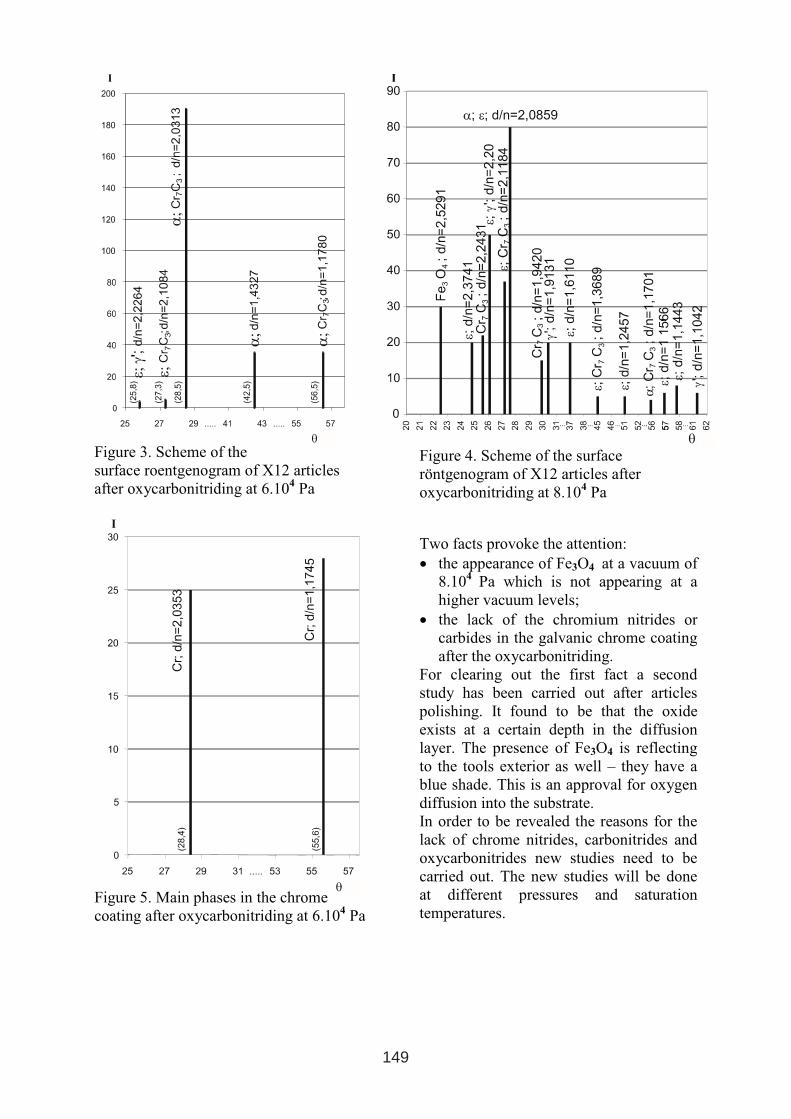
Figure 3. Scheme of the
surface roentgenogram of Х12 articles
after oxycarbonitriding at 6.104Ра
Figure 4. Scheme of the surface
röntgenogram of Х12 articles after
oxycarbonitriding at 8.104Ра
Figure 5. Main phases in the chrome
coating after oxycarbonitriding at 6.104Ра
Two facts provoke the attention:
• the appearance of Fe3О4 at a vacuum of
8.104Ра which is not appearing at a
higher vacuum levels;
• the lack of the chromium nitrides or
carbides in the galvanic chrome coating
after the oxycarbonitriding.
For clearing out the first fact a second
study has been carried out after articles
polishing. It found to be that the oxide
exists at a certain depth in the diffusion
layer. The presence of Fe3О4 is reflecting
to the tools exterior as well – they have a
blue shade. This is an approval for oxygen
diffusion into the substrate.
In order to be revealed the reasons for the
lack of chrome nitrides, carbonitrides and
oxycarbonitrides new studies need to be
carried out. The new studies will be done
at different pressures and saturation
temperatures.
149
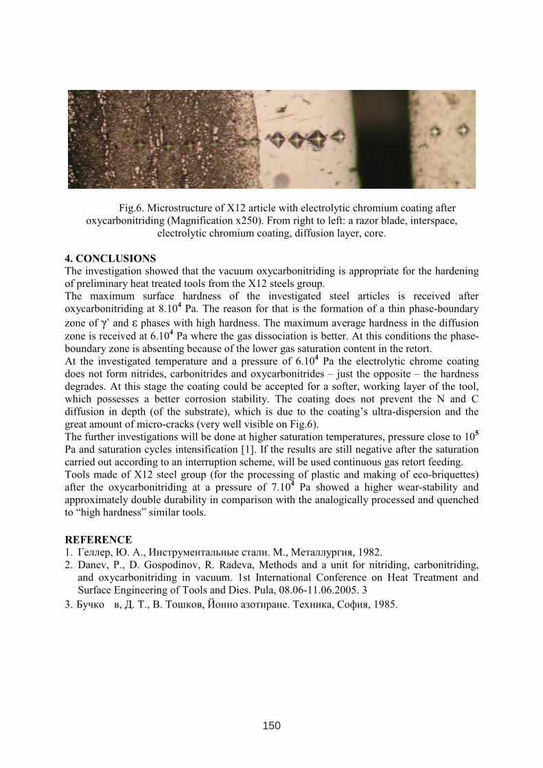
Fig.6. Microstructure of X12 article with electrolytic chromium coating after
oxycarbonitriding (Magnification x250). From right to left: a razor blade, interspace,
electrolytic chromium coating, diffusion layer, core.
4. CONCLUSIONS
The investigation showed that the vacuum oxycarbonitriding is appropriate for the hardening
of preliminary heat treated tools from the X12 steels group.
The maximum surface hardness of the investigated steel articles is received after
oxycarbonitriding at 8.104Ра. The reason for that is the formation of a thin phase-boundary
zone of γ’ and ε phases with high hardness. The maximum average hardness in the diffusion
zone is received at 6.104Ра where the gas dissociation is better. At this conditions the phase-
boundary zone is absenting because of the lower gas saturation content in the retort.
At the investigated temperature and a pressure of 6.104Ра the electrolytic chrome coating
does not form nitrides, carbonitrides and oxycarbonitrides – just the opposite – the hardness
degrades. At this stage the coating could be accepted for a softer, working layer of the tool,
which possesses a better corrosion stability. The coating does not prevent the N and C
diffusion in depth (of the substrate), which is due to the coating’s ultra-dispersion and the
great amount of micro-cracks (very well visible on Fig.6).
The further investigations will be done at higher saturation temperatures, pressure close to 105
Pa and saturation cycles intensification [1]. If the results are still negative after the saturation
carried out according to an interruption scheme, will be used continuous gas retort feeding.
Tools made of X12 steel group (for the processing of plastic and making of eco-briquettes)
after the oxycarbonitriding at a pressure of 7.104Ра showed a higher wear-stability and
approximately double durability in comparison with the analogically processed and quenched
to “high hardness” similar tools.
REFERENCE
1. Геллер,Ю. А., Инструментальные стали.М.,Металлургия, 1982.
2. Danev, P., D. Gospodinov, R. Radeva, Methods and a unit for nitriding, carbonitriding,
and oxycarbonitriding in vacuum. 1st International Conference on Heat Treatment and
Surface Engineering of Tools and Dies. Pula, 08.06-11.06.2005. 3
3. Бучко в, Д. Т., В. Тошков, Йонно азотиране. Техника, София, 1985.
150
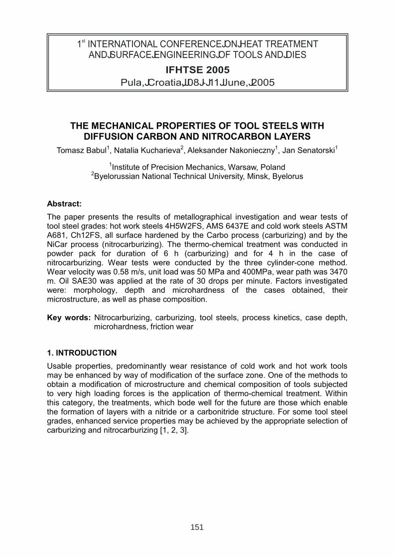
THE MECHANICAL PROPERTIES OF TOOL STEELS WITH DIFFUSION CARBON AND NITROCARBON LAYERS
Tomasz Babul1, Natalia Kucharieva2, Aleksander Nakonieczny1, Jan Senatorski1
1Institute of Precision Mechanics, Warsaw, Poland 2Byelorussian National Technical University, Minsk, Byelorus
Abstract:
The paper presents the results of metallographical investigation and wear tests of tool steel grades: hot work steels 4H5W2FS, AMS 6437E and cold work steels ASTM A681, Ch12FS, all surface hardened by the Carbo process (carburizing) and by the NiCar process (nitrocarburizing). The thermo-chemical treatment was conducted in powder pack for duration of 6 h (carburizing) and for 4 h in the case of nitrocarburizing. Wear tests were conducted by the three cylinder-cone method. Wear velocity was 0.58 m/s, unit load was 50 MPa and 400MPa, wear path was 3470 m. Oil SAE30 was applied at the rate of 30 drops per minute. Factors investigated were: morphology, depth and microhardness of the cases obtained, their microstructure, as well as phase composition.
Key words: Nitrocarburizing, carburizing, tool steels, process kinetics, case depth, microhardness, friction wear
1. INTRODUCTION
Usable properties, predominantly wear resistance of cold work and hot work tools may be enhanced by way of modification of the surface zone. One of the methods to obtain a modification of microstructure and chemical composition of tools subjected to very high loading forces is the application of thermo-chemical treatment. Within this category, the treatments, which bode well for the future are those which enable the formation of layers with a nitride or a carbonitride structure. For some tool steel grades, enhanced service properties may be achieved by the appropriate selection of carburizing and nitrocarburizing [1, 2, 3].
1 INTERNATIONAL CONFERENCE ON HEAT TREATMENT
AND SURFACE ENGINEERING OF TOOLS AND DIES
st
Pula, Croatia 08 - 11 June, 2005,
IFHTSE 2005
151
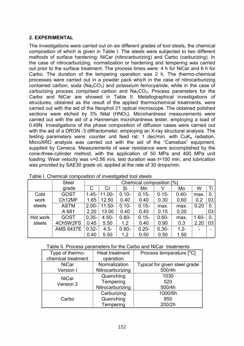
2. EXPERIMENTAL
The investigations were carried out on six different grades of tool steels, the chemical composition of which is given in Table I. The steels were subjected to two different methods of surface hardening: NiCar (nitrocarburizing) and Carbo (carburizing). In the case of nitrocarburizing, normalization or hardening and tempering was carried out prior to the surface treatment. The process times were: 4 h for NiCar and 6 h for Carbo. The duration of the tempering operation was 2 h. The thermo-chemical processes were carried out in a powder pack which in the case of nitrocarburizing contained carbon, soda (Na2CO3) and potassium ferrocyanide, while in the case of carburizing process comprised carbon and Na2CO3. Process parameters for the Carbo and NiCar are showed in Table II. Metallographical investigations of structures, obtained as the result of the applied thermochemical treatments, were carried out with the aid of the Neophot 21 optical microscope. The obtained polished sections were etched by 3% Nital (HNO3). Microhardness measurements were carried out with the aid of a Hanneman microhardness tester, employing a load of 0.49N. Investigations of the phase composition of diffusion cases were carried out with the aid of a DRON -3 diffractometer, employing an X-ray structural analysis. The testing parameters were: counter unit feed rat: 1 dec/min, with CuKα radiation. MicroXRD analysis was carried out with the aid of the “Camebax” equipment, supplied by Cameca. Measurements of wear resistance were accomplished by the cone-three-cylinder method, with the application of 50 MPa and 400 MPa unit loading. Wear velocity was v=0.56 m/s, test duration was t=100 min, and lubrication was provided by SAE30 grade oil, applied at the rate of 30 drops/min.
Table I. Chemical composition of investigated tool steels
Chemical composition [%] Steel grade C Cr Si Mn V Mo W Ti
GOST Ch12MF
1.45- 1.65
11.00- 12.50
0.10-0.40
0.15-0.40
0.15-0.30
0.40- 0.60
max.0.2
0.03
Cold worksteels ASTM
A 681 2.00-2.20
11.50- 13.00
0.10-0.40
0.15-0.45
max. 0.15
max. 0.20
0.20 0.03
GOST 4Ch5W2FS
0.35-0.45
4.50-5.50
0.80-1.2
0.15-0.40
0.60-0.90
max. 0.3
1.60-2.20
0.03
Hot worksteels
AMS 6437E 0.32-0.40
4.5-5.50
0.80-1.2
0.20-0.50
0.30-0.50
1.2-1.50
- -
Table II. Process parameters for the Carbo and NiCar treatments
Type of thermo-chemical treatment
Heat treatment operation
Process temperature [oC]
NiCar Version I
Normalization Nitrocarburizing
Typical for given steel grade 500/4h
NiCar Version 2
Quenching Tempering
Nitrocarburizing
1030 520
500/4h
Carbo Carburizing Quenching Tempering
1000/6h 850
200/2h
152
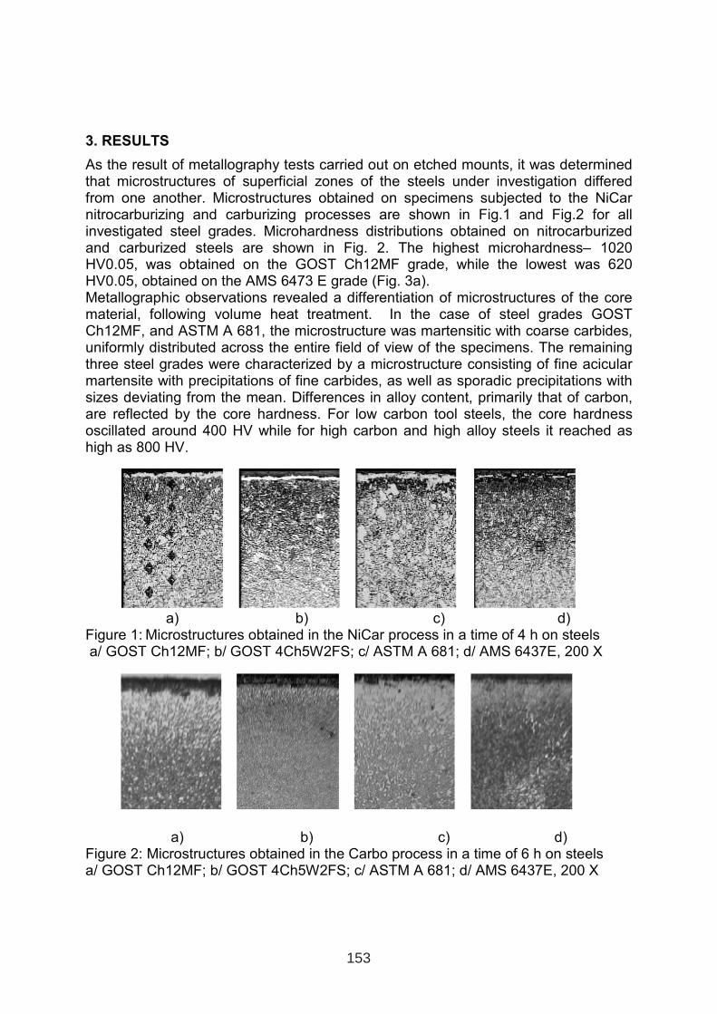
3. RESULTS
As the result of metallography tests carried out on etched mounts, it was determined that microstructures of superficial zones of the steels under investigation differed from one another. Microstructures obtained on specimens subjected to the NiCar nitrocarburizing and carburizing processes are shown in Fig.1 and Fig.2 for all investigated steel grades. Microhardness distributions obtained on nitrocarburized and carburized steels are shown in Fig. 2. The highest microhardness– 1020 HV0.05, was obtained on the GOST Ch12MF grade, while the lowest was 620 HV0.05, obtained on the AMS 6473 E grade (Fig. 3a).Metallographic observations revealed a differentiation of microstructures of the core material, following volume heat treatment. In the case of steel grades GOST Ch12MF, and ASTM A 681, the microstructure was martensitic with coarse carbides, uniformly distributed across the entire field of view of the specimens. The remaining three steel grades were characterized by a microstructure consisting of fine acicular martensite with precipitations of fine carbides, as well as sporadic precipitations with sizes deviating from the mean. Differences in alloy content, primarily that of carbon, are reflected by the core hardness. For low carbon tool steels, the core hardness oscillated around 400 HV while for high carbon and high alloy steels it reached as high as 800 HV.
a) b) c) d) Figure 1: Microstructures obtained in the NiCar process in a time of 4 h on steels a/ GOST Ch12MF; b/ GOST 4Ch5W2FS; c/ ASTM A 681; d/ AMS 6437E, 200 X
a) b) c) d) Figure 2: Microstructures obtained in the Carbo process in a time of 6 h on steelsa/ GOST Ch12MF; b/ GOST 4Ch5W2FS; c/ ASTM A 681; d/ AMS 6437E, 200 X
153
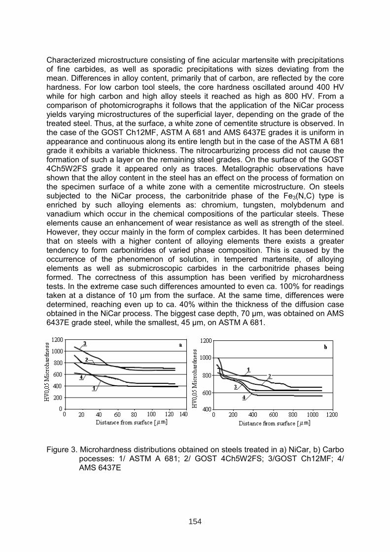
Characterized microstructure consisting of fine acicular martensite with precipitations of fine carbides, as well as sporadic precipitations with sizes deviating from the mean. Differences in alloy content, primarily that of carbon, are reflected by the core hardness. For low carbon tool steels, the core hardness oscillated around 400 HV while for high carbon and high alloy steels it reached as high as 800 HV. From a comparison of photomicrographs it follows that the application of the NiCar process yields varying microstructures of the superficial layer, depending on the grade of the treated steel. Thus, at the surface, a white zone of cementite structure is observed. In the case of the GOST Ch12MF, ASTM A 681 and AMS 6437E grades it is uniform in appearance and continuous along its entire length but in the case of the ASTM A 681 grade it exhibits a variable thickness. The nitrocarburizing process did not cause the formation of such a layer on the remaining steel grades. On the surface of the GOST 4Ch5W2FS grade it appeared only as traces. Metallographic observations have shown that the alloy content in the steel has an effect on the process of formation on the specimen surface of a white zone with a cementite microstructure. On steels subjected to the NiCar process, the carbonitride phase of the Fe3(N,C) type isenriched by such alloying elements as: chromium, tungsten, molybdenum and vanadium which occur in the chemical compositions of the particular steels. These elements cause an enhancement of wear resistance as well as strength of the steel. However, they occur mainly in the form of complex carbides. It has been determined that on steels with a higher content of alloying elements there exists a greater tendency to form carbonitrides of varied phase composition. This is caused by the occurrence of the phenomenon of solution, in tempered martensite, of alloying elements as well as submicroscopic carbides in the carbonitride phases being formed. The correctness of this assumption has been verified by microhardness tests. In the extreme case such differences amounted to even ca. 100% for readingstaken at a distance of 10 µm from the surface. At the same time, differences were determined, reaching even up to ca. 40% within the thickness of the diffusion case obtained in the NiCar process. The biggest case depth, 70 µm, was obtained on AMS 6437E grade steel, while the smallest, 45 µm, on ASTM A 681.
Figure 3. Microhardness distributions obtained on steels treated in a) NiCar, b) Carbo pocesses: 1/ ASTM A 681; 2/ GOST 4Ch5W2FS; 3/GOST Ch12MF; 4/ AMS 6437E
154
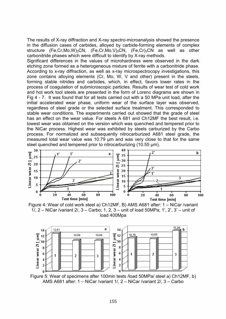
The results of X-ray diffraction and X-ray spectro-microanalysis showed the presence in the diffusion cases of carbides, alloyed by carbide-forming elements of complex structure (Fe,Cr,Mo,W)3CN, (Fe,Cr,Mo,V)3CN, (Fe,Cr)3CN as well as other carbonitride phases which were difficult to identify by X-ray methods. Significant differences in the values of microhardness were observed in the dark etching zone formed as a heterogeneous mixture of ferrite with a carbonitride phase. According to x-ray diffraction, as well as x-ray microspectrocopy investigations, this zone contains alloying elements (Cr, Mo, W, V and other) present in the steels, forming stable nitrides and carbides, which, in effect, favors lower rates in the process of coagulation of submicroscopic particles. Results of wear test of cold work and hot work tool steels are presented in the form of Lorenc diagrams are shown in Fig 4 - 7. It was found that for all tests carried out with a 50 MPa unit load, after the initial accelerated wear phase, uniform wear of the surface layer was observed, regardless of steel grade or the selected surface treatment. This corresponded to stable wear conditions. The experiments carried out showed that the grade of steel has an effect on the wear value. For steels A 681 and Ch12MF the best result, i.e. lowest wear was obtained on the version which was quenched and tempered prior to the NiCar process. Highest wear was exhibited by steels carburized by the Carbo process. For normalized and subsequently nitrocarburized A681 steel grade, the measured total wear value was 10.79 µm and was very close to that for the same steel quenched and tempered prior to nitrocarburizing (10.55 µm).
Figure 4: Wear of cold work steel a) Ch12MF, B) AMS A681 after: 1 – NiCar /variant 1/, 2 – NiCar /variant 2/, 3 – Carbo; 1, 2, 3 – unit of load 50MPa; 1’, 2’, 3’ – unit of
load 400Mpa
Figure 5: Wear of specimens after 100min tests /load 50MPa/ steel a) Ch12MF, b) AMS A681 after: 1 – NiCar /variant 1/, 2 – NiCar /variant 2/, 3 – Carbo
155
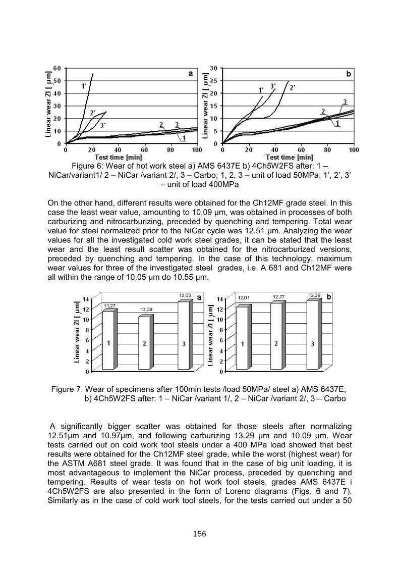
Figure 6: Wear of hot work steel a) AMS 6437E b) 4Ch5W2FS after: 1 – NiCar/variant1/ 2 – NiCar /variant 2/, 3 – Carbo; 1, 2, 3 – unit of load 50MPa; 1’, 2’, 3’
– unit of load 400MPa
On the other hand, different results were obtained for the Ch12MF grade steel. In this case the least wear value, amounting to 10.09 µm, was obtained in processes of both carburizing and nitrocarburizing, preceded by quenching and tempering. Total wear value for steel normalized prior to the NiCar cycle was 12.51 µm. Analyzing the wear values for all the investigated cold work steel grades, it can be stated that the least wear and the least result scatter was obtained for the nitrocarburized versions, preceded by quenching and tempering. In the case of this technology, maximum wear values for three of the investigated steel grades, i.e. A 681 and Ch12MF were all within the range of 10,05 µm do 10.55 µm.
Figure 7. Wear of specimens after 100min tests /load 50MPa/ steel a) AMS 6437E, b) 4Ch5W2FS after: 1 – NiCar /variant 1/, 2 – NiCar /variant 2/, 3 – Carbo
A significantly bigger scatter was obtained for those steels after normalizing 12.51µm and 10.97µm, and following carburizing 13.29 µm and 10.09 µm. Wear tests carried out on cold work tool steels under a 400 MPa load showed that best results were obtained for the Ch12MF steel grade, while the worst (highest wear) for the ASTM A681 steel grade. It was found that in the case of big unit loading, it is most advantageous to implement the NiCar process, preceded by quenching and tempering. Results of wear tests on hot work tool steels, grades AMS 6437E i 4Ch5W2FS are also presented in the form of Lorenc diagrams (Figs. 6 and 7). Similarly as in the case of cold work tool steels, for the tests carried out under a 50
156
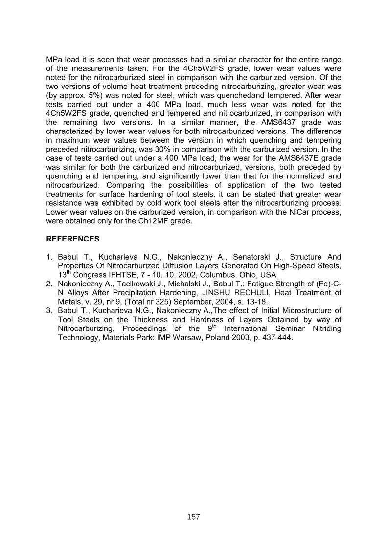
MPa load it is seen that wear processes had a similar character for the entire range of the measurements taken. For the 4Ch5W2FS grade, lower wear values were noted for the nitrocarburized steel in comparison with the carburized version. Of the two versions of volume heat treatment preceding nitrocarburizing, greater wear was (by approx. 5%) was noted for steel, which was quenchedand tempered. After wear tests carried out under a 400 MPa load, much less wear was noted for the 4Ch5W2FS grade, quenched and tempered and nitrocarburized, in comparison with the remaining two versions. In a similar manner, the AMS6437 grade wascharacterized by lower wear values for both nitrocarburized versions. The difference in maximum wear values between the version in which quenching and tempering preceded nitrocarburizing, was 30% in comparison with the carburized version. In the case of tests carried out under a 400 MPa load, the wear for the AMS6437E grade was similar for both the carburized and nitrocarburized, versions, both preceded by quenching and tempering, and significantly lower than that for the normalized and nitrocarburized. Comparing the possibilities of application of the two tested treatments for surface hardening of tool steels, it can be stated that greater wear resistance was exhibited by cold work tool steels after the nitrocarburizing process. Lower wear values on the carburized version, in comparison with the NiCar process, were obtained only for the Ch12MF grade.
REFERENCES
1. Babul T., Kucharieva N.G., Nakonieczny A., Senatorski J., Structure And Properties Of Nitrocarburized Diffusion Layers Generated On High-Speed Steels, 13th Congress IFHTSE, 7 - 10. 10. 2002, Columbus, Ohio, USA
2. Nakonieczny A., Tacikowski J., Michalski J., Babul T.: Fatigue Strength of (Fe)-C-N Alloys After Precipitation Hardening, JINSHU RECHULI, Heat Treatment of Metals, v. 29, nr 9, (Total nr 325) September, 2004, s. 13-18.
3. Babul T., Kucharieva N.G., Nakonieczny A.,The effect of Initial Microstructure of Tool Steels on the Thickness and Hardness of Layers Obtained by way of Nitrocarburizing, Proceedings of the 9th International Seminar Nitriding Technology, Materials Park: IMP Warsaw, Poland 2003, p. 437-444.
157

COMBINATION OF MILLING AND LASER BEAM MACHINING -
FOR MOULD MAKING
H.-J. Pieper; E. Wolf; M. Krause
Otto-von-Guericke-University of Magdeburg
Institute of Manufacturing Technology and Quality Management (IFQ)
Universitätsplatz 2; 39106 Magdeburg; Germany
ABSTRACT
By producing small numbers of micro moulds are flexible producing methods necessary. This
study investigates the successive combination of milling and laser beam machining for
producing filigree structures. Advantages and limits are shown, the technique is introduced
and the CAD-CAM interface is explained.
Furthermore the paper presents the investigation on surface quality, material removal, when
machining with a combination of milling and laser beam machining for roughing and
finishing, respectively.
KEYWORDS: laser machining, mould making, rapid tooling technologies, micro
engineering technology
1. INTRODUCTION
In the last years, industry has witnessed an increasing demand of tools capable of quickly
giving parts most diverse geometries. Often it is necessary to produce work pieces with
laterally structure dimensions smaller 1mm. For this case of applications, the innovative
process combination of milling and laser machining seems to be a suitable method [1-4].
Advantages of this strategy are:
• high process flexibility and a high degree of automation based on NC-controls and
linkage to CAD-CAM process chains
• possibility to produce real three dimensional micro structures in short time
• no costs for producing EDM-electrodes and EDM-process
• especially useable for small numbers of work pieces and moulds with micro structures
1 INTERNATIONAL CONFERENCE ON HEAT TREATMENT
AND SURFACE ENGINEERING OF TOOLS AND DIES
st
Pula, Croatia 08 - 11 June, 2005,
IFHTSE 2005
159
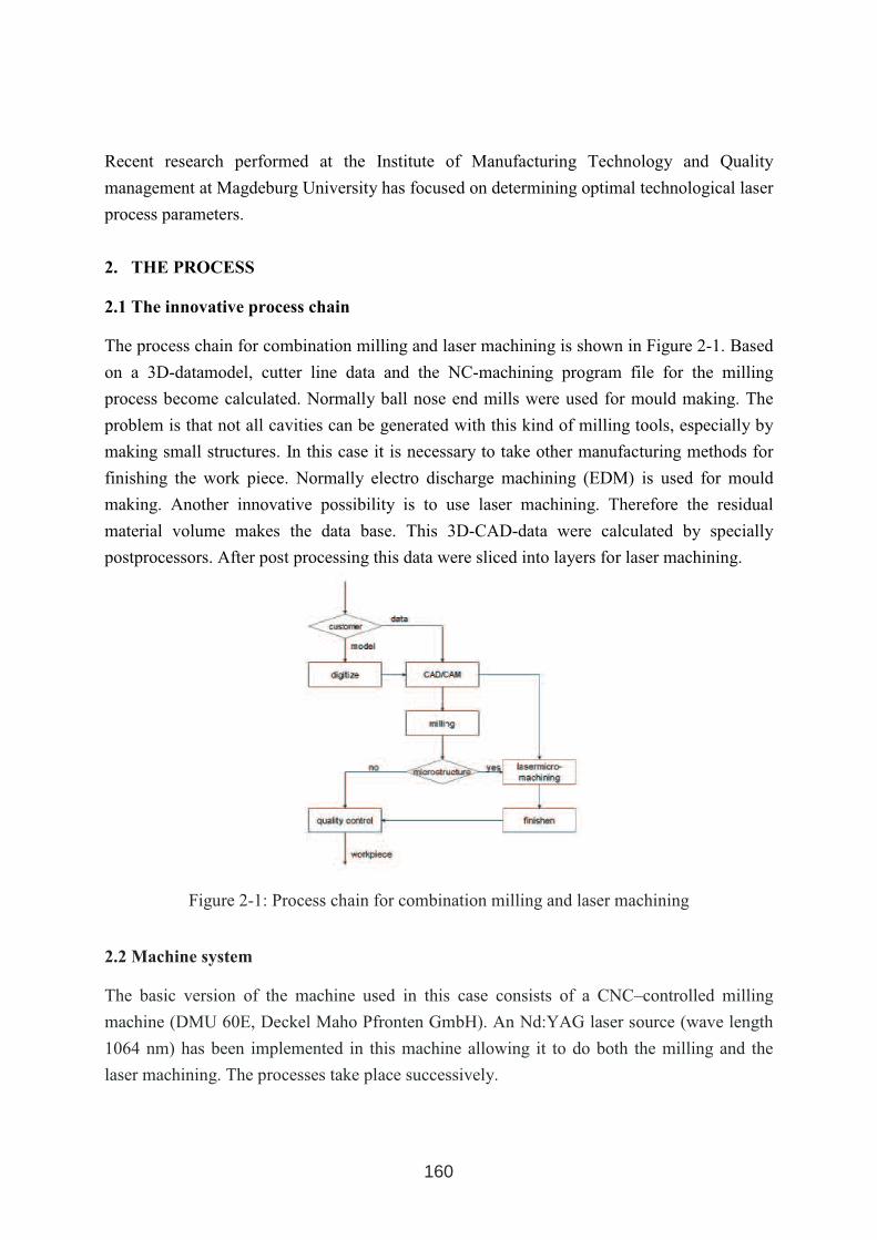
Recent research performed at the Institute of Manufacturing Technology and Quality
management at Magdeburg University has focused on determining optimal technological laser
process parameters.
2. THE PROCESS
2.1 The innovative process chain
The process chain for combination milling and laser machining is shown in Figure 2-1. Based
on a 3D-datamodel, cutter line data and the NC-machining program file for the milling
process become calculated. Normally ball nose end mills were used for mould making. The
problem is that not all cavities can be generated with this kind of milling tools, especially by
making small structures. In this case it is necessary to take other manufacturing methods for
finishing the work piece. Normally electro discharge machining (EDM) is used for mould
making. Another innovative possibility is to use laser machining. Therefore the residual
material volume makes the data base. This 3D-CAD-data were calculated by specially
postprocessors. After post processing this data were sliced into layers for laser machining.
Figure 2-1: Process chain for combination milling and laser machining
2.2 Machine system
The basic version of the machine used in this case consists of a CNC–controlled milling
machine (DMU 60E, Deckel Maho Pfronten GmbH). An Nd:YAG laser source (wave length
1064 nm) has been implemented in this machine allowing it to do both the milling and the
laser machining. The processes take place successively.
160
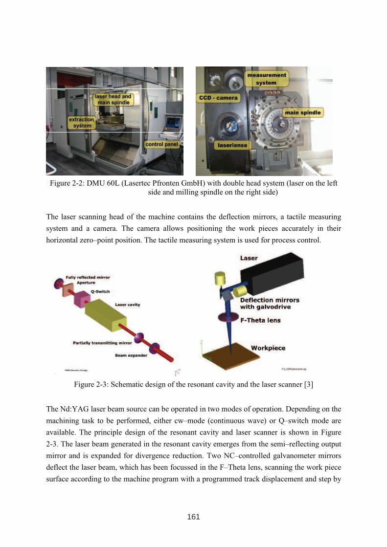
Figure 2-2: DMU 60L (Lasertec Pfronten GmbH) with double head system (laser on the left
side and milling spindle on the right side)
The laser scanning head of the machine contains the deflection mirrors, a tactile measuring
system and a camera. The camera allows positioning the work pieces accurately in their
horizontal zero–point position. The tactile measuring system is used for process control.
Figure 2-3: Schematic design of the resonant cavity and the laser scanner [3]
The Nd:YAG laser beam source can be operated in two modes of operation. Depending on the
machining task to be performed, either cw–mode (continuous wave) or Q–switch mode are
available. The principle design of the resonant cavity and laser scanner is shown in Figure
2-3. The laser beam generated in the resonant cavity emerges from the semi–reflecting output
mirror and is expanded for divergence reduction. Two NC–controlled galvanometer mirrors
deflect the laser beam, which has been focussed in the F–Theta lens, scanning the work piece
surface according to the machine program with a programmed track displacement and step by
161
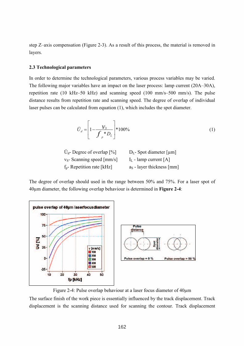
step Z–axis compensation (Figure 2-3). As a result of this process, the material is removed in
layers.
2.3 Technological parameters
In order to determine the technological parameters, various process variables may be varied.
The following major variables have an impact on the laser process: lamp current (20A–30A),
repetition rate (10 kHz–50 kHz) and scanning speed (100 mm/s–500 mm/s). The pulse
distance results from repetition rate and scanning speed. The degree of overlap of individual
laser pulses can be calculated from equation (1), which includes the spot diameter.
%100**
1
−=
Lp
Sd
DÜ
fv
(1)
Üd- Degree of overlap [%] DL- Spot diameter [µm]
vS- Scanning speed [mm/s] IL - lamp current [A]
fp- Repetition rate [kHz] aS - layer thickness [mm]
The degree of overlap should used in the range between 50% and 75%. For a laser spot of
40µm diameter, the following overlap behaviour is determined in Figure 2-4:
Figure 2-4: Pulse overlap behaviour at a laser focus diameter of 40µm
The surface finish of the work piece is essentially influenced by the track displacement. Track
displacement is the scanning distance used for scanning the contour. Track displacement
162
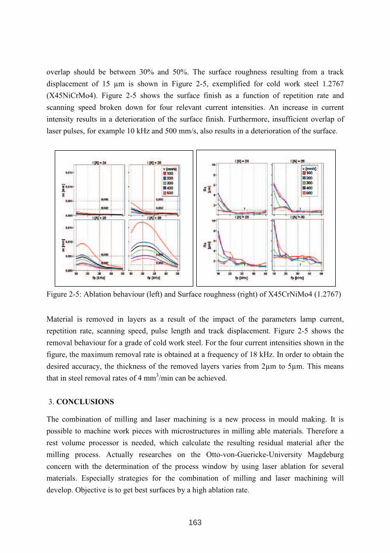
overlap should be between 30% and 50%. The surface roughness resulting from a track
displacement of 15 µm is shown in Figure 2-5, exemplified for cold work steel 1.2767
(X45NiCrMo4). Figure 2-5 shows the surface finish as a function of repetition rate and
scanning speed broken down for four relevant current intensities. An increase in current
intensity results in a deterioration of the surface finish. Furthermore, insufficient overlap of
laser pulses, for example 10 kHz and 500 mm/s, also results in a deterioration of the surface.
Figure 2-5: Ablation behaviour (left) and Surface roughness (right) of X45CrNiMo4 (1.2767)
Material is removed in layers as a result of the impact of the parameters lamp current,
repetition rate, scanning speed, pulse length and track displacement. Figure 2-5 shows the
removal behaviour for a grade of cold work steel. For the four current intensities shown in the
figure, the maximum removal rate is obtained at a frequency of 18 kHz. In order to obtain the
desired accuracy, the thickness of the removed layers varies from 2µm to 5µm. This means
that in steel removal rates of 4 mm3/min can be achieved.
3. CONCLUSIONS
The combination of milling and laser machining is a new process in mould making. It is
possible to machine work pieces with microstructures in milling able materials. Therefore a
rest volume processor is needed, which calculate the resulting residual material after the
milling process. Actually researches on the Otto-von-Guericke-University Magdeburg
concern with the determination of the process window by using laser ablation for several
materials. Especially strategies for the combination of milling and laser machining will
develop. Objective is to get best surfaces by a high ablation rate.
163
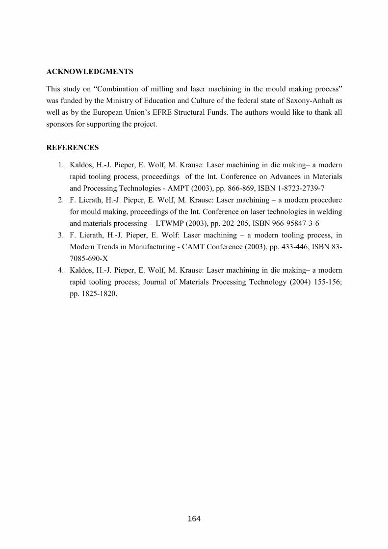
ACKNOWLEDGMENTS
This study on “Combination of milling and laser machining in the mould making process”
was funded by the Ministry of Education and Culture of the federal state of Saxony-Anhalt as
well as by the European Union’s EFRE Structural Funds. The authors would like to thank all
sponsors for supporting the project.
REFERENCES
1. Kaldos, H.-J. Pieper, E. Wolf, M. Krause: Laser machining in die making– a modern
rapid tooling process, proceedings of the Int. Conference on Advances in Materials
and Processing Technologies - AMPT (2003), pp. 866-869, ISBN 1-8723-2739-7
2. F. Lierath, H.-J. Pieper, E. Wolf, M. Krause: Laser machining – a modern procedure
for mould making, proceedings of the Int. Conference on laser technologies in welding
and materials processing - LTWMP (2003), pp. 202-205, ISBN 966-95847-3-6
3. F. Lierath, H.-J. Pieper, E. Wolf: Laser machining – a modern tooling process, in
Modern Trends in Manufacturing - CAMT Conference (2003), pp. 433-446, ISBN 83-
7085-690-X
4. Kaldos, H.-J. Pieper, E. Wolf, M. Krause: Laser machining in die making– a modern
rapid tooling process; Journal of Materials Processing Technology (2004) 155-156;
pp. 1825-1820.
164
TRIBOLOGICAL PROPERTIES OF SURFACE ENGINEERED HOT
WORK TOOL STEEL FOR ALUMINIUM EXTRUSION DIES
M. Pellizzari, M. Zadra, A. Molinari
Department of Materials Engineering and Industrial Technologies
University of Trento, Via Mesiano 77, 38050 Trento, Italy
ABSTRACT
A tribological test aimed at the simulation of aluminium hot extrusion was realized. A 6082-
Al disc, induction heated up to a maximum surface temperature of 350°C, is allowed to rotate
against a conformal hot work steel block, simulating the extrusion die. The test well
reproduces the wear mechanism observed during in-service conditions. After an initial period,
the hot plasticized Al progressively adheres to the steel counterpart thus allowing direct Al-Al
contact. The high shear stresses given by the strong adhesion produces the nucleation of deep
cracks which strongly deteriorate the surface of the steel by delamination.
Hot work tool steel (AISI H11) is employed for the realization of extrusion dies. Salth bath
nitriding (Tenifer) is usually carried out to improve wear resistance. The possible application
of PVD (CrN, TiAlN) and CVD (TiC+TiN) hard coatings, exhibiting lower compatibility
versus Al, has been evaluated in this work.
The occurrence of two distinct damage regimes was detected: a regime 1, showing minor
excursions of the friction coefficient µ is followed by a regime 2, characterized by fully
plastic Al-Al contact, with large fluctuations of µ. A time to transition (tT) has been identified
as indicative of the ability of a surface layer in delaying the occurrence of regime 2.
tT is correlated to the chemical compatibility of the surface layer (compound layer, PVD or
CVD coating) versus Al. Furthermore tT is related to the mechanical stability of the surface
layer. A generalized and severe form of wear can be appreciated by nitrided steel while a
localized and less severe form of wear can be appreciated by duplex treated, nitriding+PVD,
steel. No wear traces were observed by CVD TiC+TiN coated steel, providing the best
performance among the surface treatment here investigated.
Keywords: hot extrusion, aluminium, nitriding, PVD, CVD
1 INTERNATIONAL CONFERENCE ON HEAT TREATMENT
AND SURFACE ENGINEERING OF TOOLS AND DIES
st
Pula, Croatia 08 - 11 June, 2005,
IFHTSE 2005
165
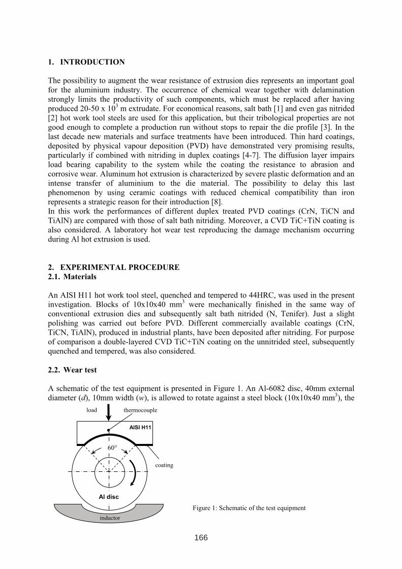
1. INTRODUCTION
The possibility to augment the wear resistance of extrusion dies represents an important goal
for the aluminium industry. The occurrence of chemical wear together with delamination
strongly limits the productivity of such components, which must be replaced after having
produced 20-50 x 103
m extrudate. For economical reasons, salt bath [1] and even gas nitrided
[2] hot work tool steels are used for this application, but their tribological properties are not
good enough to complete a production run without stops to repair the die profile [3]. In the
last decade new materials and surface treatments have been introduced. Thin hard coatings,
deposited by physical vapour deposition (PVD) have demonstrated very promising results,
particularly if combined with nitriding in duplex coatings [4-7]. The diffusion layer impairs
load bearing capability to the system while the coating the resistance to abrasion and
corrosive wear. Aluminum hot extrusion is characterized by severe plastic deformation and an
intense transfer of aluminium to the die material. The possibility to delay this last
phenomenon by using ceramic coatings with reduced chemical compatibility than iron
represents a strategic reason for their introduction [8].
In this work the performances of different duplex treated PVD coatings (CrN, TiCN and
TiAlN) are compared with those of salt bath nitriding. Moreover, a CVD TiC+TiN coating is
also considered. A laboratory hot wear test reproducing the damage mechanism occurring
during Al hot extrusion is used.
2. EXPERIMENTAL PROCEDURE
2.1. Materials
An AISI H11 hot work tool steel, quenched and tempered to 44HRC, was used in the present
investigation. Blocks of 10x10x40 mm3
were mechanically finished in the same way of
conventional extrusion dies and subsequently salt bath nitrided (N, Tenifer). Just a slight
polishing was carried out before PVD. Different commercially available coatings (CrN,
TiCN, TiAlN), produced in industrial plants, have been deposited after nitriding. For purpose
of comparison a double-layered CVD TiC+TiN coating on the unnitrided steel, subsequently
quenched and tempered, was also considered.
2.2. Wear test
A schematic of the test equipment is presented in Figure 1. An Al-6082 disc, 40mm external
diameter (d), 10mm width (w), is allowed to rotate against a steel block (10x10x40 mm3), the
Φ16
AISI H11
load
inductor
coating
thermocouple
Al disc
60°
)
Figure 1: Schematic of the test equipment
166
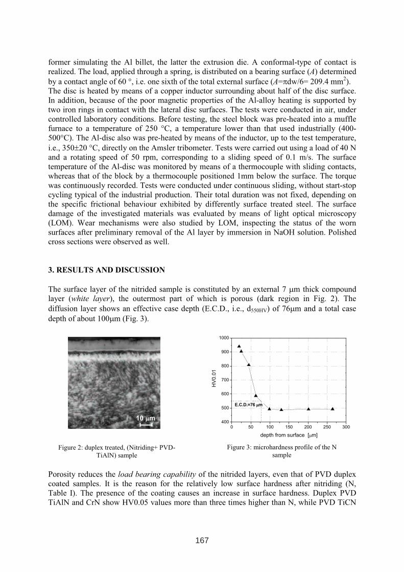
former simulating the Al billet, the latter the extrusion die. A conformal-type of contact is
realized. The load, applied through a spring, is distributed on a bearing surface (A) determined
by a contact angle of 60 °, i.e. one sixth of the total external surface (A=πdw/6= 209.4 mm2).
The disc is heated by means of a copper inductor surrounding about half of the disc surface.
In addition, because of the poor magnetic properties of the Al-alloy heating is supported by
two iron rings in contact with the lateral disc surfaces. The tests were conducted in air, under
controlled laboratory conditions. Before testing, the steel block was pre-heated into a muffle
furnace to a temperature of 250 °C, a temperature lower than that used industrially (400-
500°C). The Al-disc also was pre-heated by means of the inductor, up to the test temperature,
i.e., 350±20 °C, directly on the Amsler tribometer. Tests were carried out using a load of 40 N
and a rotating speed of 50 rpm, corresponding to a sliding speed of 0.1 m/s. The surface
temperature of the Al-disc was monitored by means of a thermocouple with sliding contacts,
whereas that of the block by a thermocouple positioned 1mm below the surface. The torque
was continuously recorded. Tests were conducted under continuous sliding, without start-stop
cycling typical of the industrial production. Their total duration was not fixed, depending on
the specific frictional behaviour exhibited by differently surface treated steel. The surface
damage of the investigated materials was evaluated by means of light optical microscopy
(LOM). Wear mechanisms were also studied by LOM, inspecting the status of the worn
surfaces after preliminary removal of the Al layer by immersion in NaOH solution. Polished
cross sections were observed as well.
3. RESULTS AND DISCUSSION
The surface layer of the nitrided sample is constituted by an external 7 µm thick compound
layer (white layer), the outermost part of which is porous (dark region in Fig. 2). The
diffusion layer shows an effective case depth (E.C.D., i.e., d550HV) of 76µm and a total case
depth of about 100µm (Fig. 3).
Porosity reduces the load bearing capability of the nitrided layers, even that of PVD duplex
coated samples. It is the reason for the relatively low surface hardness after nitriding (N,
Table I). The presence of the coating causes an increase in surface hardness. Duplex PVD
TiAlN and CrN show HV0.05 values more than three times higher than N, while PVD TiCN
10 µµm
0 50 100 150 200 250 300400
500
600
700
800
900
1000
E.C.D.=76 µµm
HV
0.0
1
depth from surface [µm]
Figure 2: duplex treated, (Nitriding+ PVD-
TiAlN) sample
Figure 3: microhardness profile of the N
sample
167
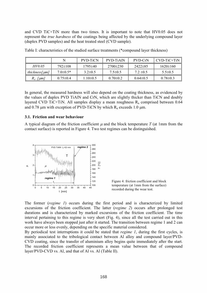
and CVD TiC+TiN more than two times. It is important to note that HV0.05 does not
represent the true hardness of the coatings being affected by the underlying compound layer
(duplex PVD samples) and the heat treated steel (CVD sample).
Table I: characteristics of the studied surface treatments (*compound layer thickness)
N PVD-TiCN PVD-TiAlN PVD-CrN CVD-TiC+TiN
HV0.05 792±108 1795±40 2700±230 2422±85 1620±160
thickness[µm] 7.0±0.5* 3.2±0.5 7.5±0.5 7.2 ±0.5 5.5±0.5
Ra [µm] 0.75±0.4 1.10±0.5 0.70±0.2 0.64±0.5 0.78±0.3
In general, the measured hardness will also depend on the coating thickness, as evidenced by
the values of duplex PVD TiAlN and CrN, which are slightly thicker than TiCN and doubly
layered CVD TiC+TiN. All samples display a mean roughness Ra comprised between 0.64
and 0.78 µm with exception of PVD-TiCN by which Ra exceeds 1.0 µm.
3.1. Friction and wear behaviour
A typical diagram of the friction coefficient µ and the block temperature T (at 1mm from the
contact surface) is reported in Figure 4. Two test regimes can be distinguished.
The former (regime 1) occurs during the first period and is characterized by limited
excursions of the friction coefficient. The latter (regime 2) occurs after prolonged test
durations and is characterized by marked excursions of the friction coefficient. The time
interval pertaining to this regime is very short (Fig. 4), since all the test carried out in this
work have always been stopped just after it started. The transition between regime 1 and 2 can
occur more or less evenly, depending on the specific material considered.
By periodical test interruptions it could be stated that regime 1, during the first cycles, is
mainly associated to the tribological contact between Al alloy and compound layer/PVD-
CVD coating, since the transfer of aluminium alloy begins quite immediately after the start.
The recorded friction coefficient represents a mean value between that of compound
layer/PVD-CVD vs. Al, and that of Al vs. Al (Table II).
0 5 10 15 20 25 30 35 40 450
1
2
3
4
100
120
140
160
180
200
220
240
260
280
300regime 2
regime 1
µµ
t [min]
PVD TiAlN tT=32 min
T
tT
T[°
C]
Figure 4: friction coefficient and block
temperature (at 1mm from the surface)
recorded during the wear test.
168
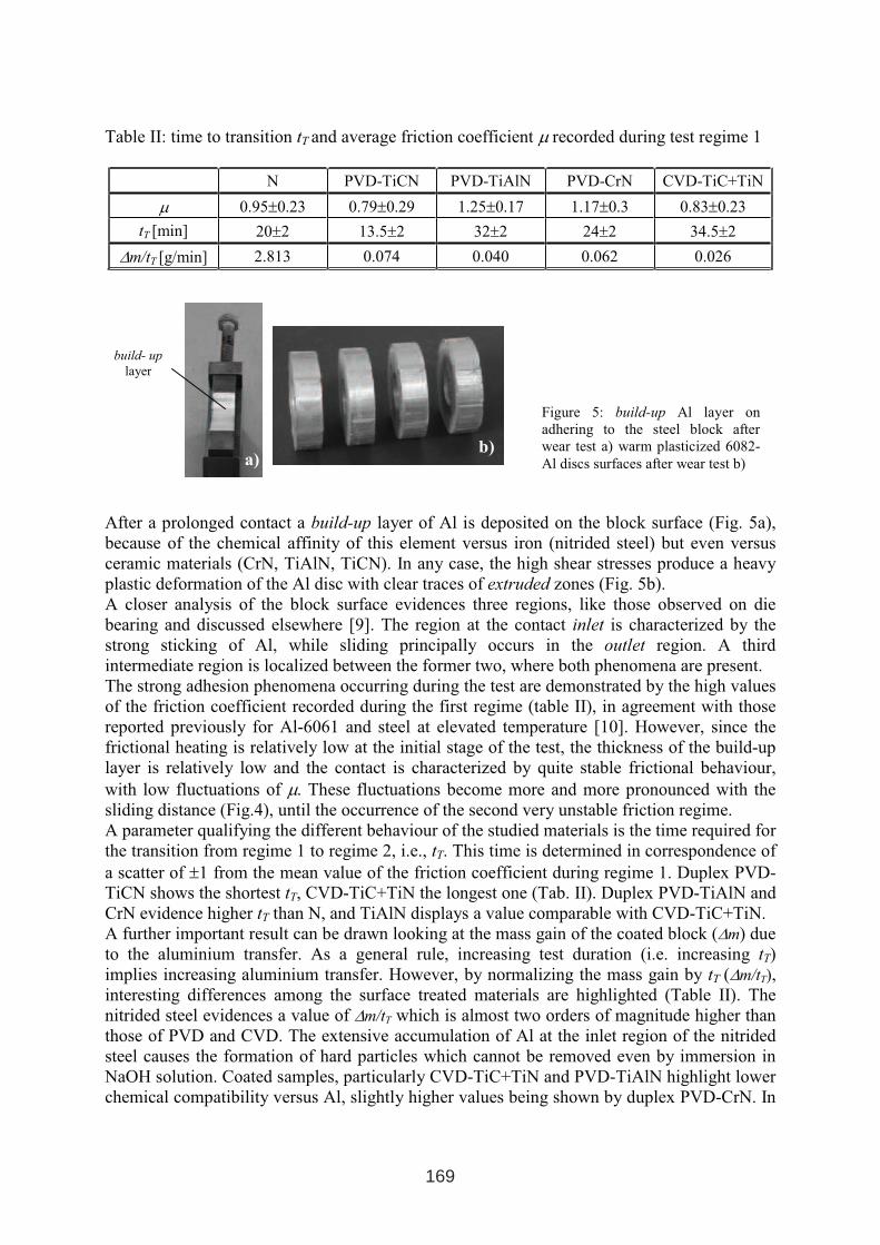
Table II: time to transition tT and average friction coefficient µ recorded during test regime 1
N PVD-TiCN PVD-TiAlN PVD-CrN CVD-TiC+TiN
µ 0.95±0.23 0.79±0.29 1.25±0.17 1.17±0.3 0.83±0.23
tT [min] 20±2 13.5±2 32±2 24±2 34.5±2
∆m/tT [g/min] 2.813 0.074 0.040 0.062 0.026
After a prolonged contact a build-up layer of Al is deposited on the block surface (Fig. 5a),
because of the chemical affinity of this element versus iron (nitrided steel) but even versus
ceramic materials (CrN, TiAlN, TiCN). In any case, the high shear stresses produce a heavy
plastic deformation of the Al disc with clear traces of extruded zones (Fig. 5b).
A closer analysis of the block surface evidences three regions, like those observed on die
bearing and discussed elsewhere [9]. The region at the contact inlet is characterized by the
strong sticking of Al, while sliding principally occurs in the outlet region. A third
intermediate region is localized between the former two, where both phenomena are present.
The strong adhesion phenomena occurring during the test are demonstrated by the high values
of the friction coefficient recorded during the first regime (table II), in agreement with those
reported previously for Al-6061 and steel at elevated temperature [10]. However, since the
frictional heating is relatively low at the initial stage of the test, the thickness of the build-up
layer is relatively low and the contact is characterized by quite stable frictional behaviour,
with low fluctuations of µ. These fluctuations become more and more pronounced with the
sliding distance (Fig.4), until the occurrence of the second very unstable friction regime.
A parameter qualifying the different behaviour of the studied materials is the time required for
the transition from regime 1 to regime 2, i.e., tT. This time is determined in correspondence of
a scatter of ±1 from the mean value of the friction coefficient during regime 1. Duplex PVD-
TiCN shows the shortest tT, CVD-TiC+TiN the longest one (Tab. II). Duplex PVD-TiAlN and
CrN evidence higher tT than N, and TiAlN displays a value comparable with CVD-TiC+TiN.
A further important result can be drawn looking at the mass gain of the coated block (∆m) due
to the aluminium transfer. As a general rule, increasing test duration (i.e. increasing tT)
implies increasing aluminium transfer. However, by normalizing the mass gain by tT (∆m/tT),
interesting differences among the surface treated materials are highlighted (Table II). The
nitrided steel evidences a value of ∆m/tT which is almost two orders of magnitude higher than
those of PVD and CVD. The extensive accumulation of Al at the inlet region of the nitrided
steel causes the formation of hard particles which cannot be removed even by immersion in
NaOH solution. Coated samples, particularly CVD-TiC+TiN and PVD-TiAlN highlight lower
chemical compatibility versus Al, slightly higher values being shown by duplex PVD-CrN. In
a)b)
build- up
layer
Figure 5: build-up Al layer on
adhering to the steel block after
wear test a) warm plasticized 6082-
Al discs surfaces after wear test b)
169
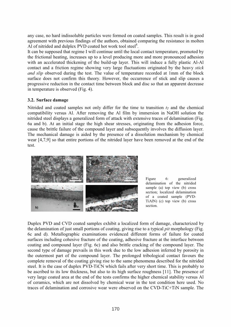
any case, no hard indissoluble particles were formed on coated samples. This result is in good
agreement with previous findings of the authors, obtained comparing the resistance in molten
Al of nitrided and dulplex PVD coated hot work tool steel8.
It can be supposed that regime I will continue until the local contact temperature, promoted by
the frictional heating, increases up to a level producing more and more pronounced adhesion
with an accelerated thickening of the build-up layer. This will induce a fully plastic Al-Al
contact and a friction regime showing very large fluctuations originated by the heavy stick
and slip observed during the test. The value of temperature recorded at 1mm of the block
surface does not confirm this theory. However, the occurrence of stick and slip causes a
progressive reduction in the contact time between block and disc so that an apparent decrease
in temperature is observed (Fig. 4).
3.2. Surface damage
Nitrided and coated samples not only differ for the time to transition tT and the chemical
compatibility versus Al. After removing the Al film by immersion in NaOH solution the
nitrided steel displays a generalized form of attack with extensive traces of delamination (Fig.
6a and b). At an initial stage the high shear stresses, originating from the adhesion force,
cause the brittle failure of the compound layer and subsequently involves the diffusion layer.
The mechanical damage is aided by the presence of a dissolution mechanism by chemical
wear [4,7,9] so that entire portions of the nitrided layer have been removed at the end of the
test.
Duplex PVD and CVD coated samples exhibit a localized form of damage, characterized by
the delamination of just small portions of coating, giving rise to a typical pit morphology (Fig.
6c and d). Metallographic examinations evidenced different forms of failure for coated
surfaces including cohesive fracture of the coating, adhesive fracture at the interface between
coating and compound layer (Fig. 6c) and also brittle cracking of the compound layer. The
second type of damage prevails in this work due to the low adhesion inferred by porosity in
the outermost part of the compound layer. The prolonged tribological contact favours the
complete removal of the coating giving rise to the same phenomena described for the nitrided
steel. It is the case of duplex PVD-TiCN which fails after very short time. This is probably to
be ascribed to its low thickness, but also to its high surface roughness [11]. The presence of
very large coated area at the end of the tests confirms the higher chemical stability versus Al
of ceramics, which are not dissolved by chemical wear in the test condition here used. No
traces of delamination and corrosive wear were observed on the CVD-TiC+TiN sample. The
a)
b)
c)
d) 50µµ
200µµ200µµ
10µµ
Figure 6: generalized
delamination of the nitrided
sample (a) top view (b) cross
section; localized delamination
of a coated sample (PVD-
TiAlN) (c) top view (b) cross
section.
170
high adhesion between steel and coating, arising from the high deposition temperature (and
not disturbed by the presence of a porous compound layer) ensure very good mechanical
stability of the bonding layer and high surface durability for the CVD coated sample.
4. CONCLUSION
• A tribological test aimed at the reproduction of the damage occurring during aluminium
hot extrusion has been proposed. It is characterized by conformal type contact between a
steel block (extrusion die) and a 6082-Al disc (Al billet). The results confirm that the wear
mechanism occurring in service is fairly well reproduced.
• The friction coefficient highlights the occurrence of two regimes. Regime 1, mostly
characterized by the contact between surface treated steel and Al alloy is quite stable and
shows minor excursion of µ. Regime 2, characterized by full Al-Al contact, is quite
unstable, showing large fluctuations of µ.
• A time to transition (tT) has been identified as indicative of the ability of a surface layer to
delay the occurrence of regime 2. tT is correlated to the chemical compatibility of the
surface layer (compound layer, PVD or CVD coating) versus Al, i.e., to the tendency
towards the formation of build-up Al layer. Lower specific mass gain (∆m/tT) due to Al
transfer were observed for materials showing the highest tT, namely PVD-TiAlN and CVD
TiC+TiN. tT is related to the load bearing capability of the engineered surface layer and
to the interfacial adhesion between coating and underlying compound layer (duplex
PVD)/steel (CVD).
• A generalized and severe form of wear can be appreciated on the nitrided steel involving
subsurface cracking and delamination. A localized and weaker form of wear can be
appreciated on duplex treated, nitriding+PVD, steel. No wear traces were observed on
CDV TiC+TiN coated steel, providing the best performance among the surface treatment
here investigated. These have been principally ascribed to the higher interfacial bonding
strength of this system, by which the absence of the porous compound layer does not
negatively affect adhesion. Very good properties were also displayed by duplex PVD-
TiAlN.
171

HARD COATINGS TO PREVENT THE WASHOUT PHENOMENA IN
HIGH PRESSURE DIE CASTING TOOLS
D. Ugues1, E. Torres Miranda
1, M. Perucca
2, M. Albertinazzi
3, M. Rosso
1
1Politecnico di Torino, Dipartimento di Scienza dei Materiali e Ingegneria Chimica,
Cso Duca degli Abruzzi 24, I 10129 Torino (Italy)
2Clean NT Lab, Environment Park, Via Livorno 58/60, I 10144 Torino (Italy)
3Teksid Aluminum srl, Via G. Agnelli 60, 10022 Carmagnola (Torino) (Italy)
ABSTRACT
Hard thin coatings were deposited on a hot working tool steel so as to enhance its resistance
to washout in high pressure die casting application. The washout is a complex phenomenon of
degradation where erosion, soldering, corrosion usually occur jointly. All of these phenomena
major sources of limitation to the die service life. The application of hard PVD coatings may
result efficient against these degradation mechanisms when applied on particular parts of the
die: e.g. the inlet and the pins.
A CrAlSiN coating system was deposited on the base material and different modulations of
the chemical composition were developed so as to increase either the chromium or the
aluminium-silicon content.
A set of coated specimens was directly analyzed through optical and electronic microscopy, to
assess their overall quality. Another set of specimens was subjected to cyclic immersions in a
molten aluminium alloy bath. The washout signs were detected and monitored in function of
the increasing number of cycles. The onset of soldering was mainly investigated through
periodic electron microscopy inspections.
Keywors: PVD ceramic coatings, aluminium die casting, washout, soldering, chemical
composition modulation
1 INTERNATIONAL CONFERENCE ON HEAT TREATMENT
AND SURFACE ENGINEERING OF TOOLS AND DIES
st
Pula, Croatia 08 - 11 June, 2005,
IFHTSE 2005
173
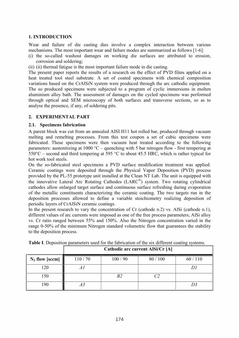
1. INTRODUCTION
Wear and failure of die casting dies involve a complex interaction between various
mechanisms. The most important wear and failure modes are summarized as follows [1-6]:
(i) the so-called washout damages on working die surfaces are attributed to erosion,
corrosion and soldering;
(ii) (ii) thermal fatigue is the most important failure mode in die casting.
The present paper reports the results of a research on the effect of PVD films applied on a
heat treated tool steel substrate. A set of coated specimens with chemical composition
variations based on the CrAlSiN system were produced through the arc cathodic equipment.
The so produced specimens were subjected to a program of cyclic immersions in molten
aluminium alloy bath. The assessment of damages on the cycled specimens was performed
through optical and SEM microscopy of both surfaces and transverse sections, so as to
analyse the presence, if any, of soldering pits.
2. EXPERIMENTAL PART
2.1. Specimens fabrication
A parent block was cut from an annealed AISI H11 hot rolled bar, produced through vacuum
melting and remelting processes. From this test coupon a set of cubic specimens were
fabricated. These specimens were then vacuum heat treated according to the following
parameters: austenitizing at 1000 °C – quenching with 5 bar nitrogen flow - first tempering at
550°C – second and third tempering at 595 °C to about 45.5 HRC, which is rather typical for
hot work tool steels.
On the so-fabricated steel specimens a PVD surface modification treatment was applied.
Ceramic coatings were deposited through the Physical Vapor Deposition (PVD) process
provided by the PL-55 prototype unit installed at the Clean NT Lab. The unit is equipped with
the innovative Lateral Arc Rotating Cathodes (LARC
) system. Two rotating cylindrical
cathodes allow enlarged target surface and continuous surface refreshing during evaporation
of the metallic constituents characterizing the ceramic coating. The two targets run in the
deposition processes allowed to define a variable stoichiometry realizing deposition of
periodic layers of CrAlSiN ceramic coatings.
In the present research to vary the concentration of Cr (cathode n.2) vs. AlSi (cathode n.1),
different values of arc currents were imposed as one of the free process parameters; AlSi alloy
vs. Cr ratio ranged between 55% and 150%. Also the Nitrogen concentration varied in the
range 0-50% of the minimum Nitrogen standard volumetric flow that guarantees the stability
to the deposition process.
Table I. Deposition parameters used for the fabrication of the six different coating systems.
Cathodic arc current AlSi/Cr [A]
N2 flow [sccm] 110 / 70 100 / 90 80 / 100 60 / 110
120 A1 D1
150 B2 C2
190 A3 D3
174
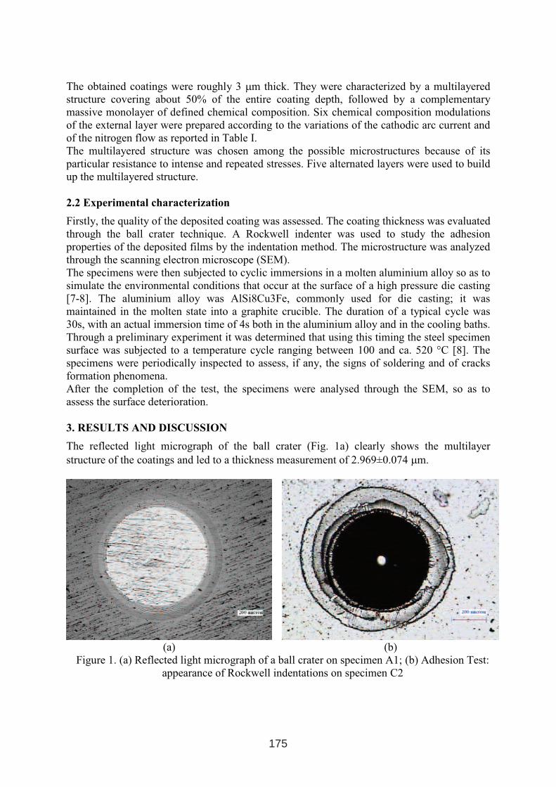
The obtained coatings were roughly 3 µm thick. They were characterized by a multilayered
structure covering about 50% of the entire coating depth, followed by a complementary
massive monolayer of defined chemical composition. Six chemical composition modulations
of the external layer were prepared according to the variations of the cathodic arc current and
of the nitrogen flow as reported in Table I.
The multilayered structure was chosen among the possible microstructures because of its
particular resistance to intense and repeated stresses. Five alternated layers were used to build
up the multilayered structure.
2.2 Experimental characterization
Firstly, the quality of the deposited coating was assessed. The coating thickness was evaluated
through the ball crater technique. A Rockwell indenter was used to study the adhesion
properties of the deposited films by the indentation method. The microstructure was analyzed
through the scanning electron microscope (SEM).
The specimens were then subjected to cyclic immersions in a molten aluminium alloy so as to
simulate the environmental conditions that occur at the surface of a high pressure die casting
[7-8]. The aluminium alloy was AlSi8Cu3Fe, commonly used for die casting; it was
maintained in the molten state into a graphite crucible. The duration of a typical cycle was
30s, with an actual immersion time of 4s both in the aluminium alloy and in the cooling baths.
Through a preliminary experiment it was determined that using this timing the steel specimen
surface was subjected to a temperature cycle ranging between 100 and ca. 520 °C [8]. The
specimens were periodically inspected to assess, if any, the signs of soldering and of cracks
formation phenomena.
After the completion of the test, the specimens were analysed through the SEM, so as to
assess the surface deterioration.
3. RESULTS AND DISCUSSION
The reflected light micrograph of the ball crater (Fig. 1a) clearly shows the multilayer
structure of the coatings and led to a thickness measurement of 2.969±0.074 µm.
(a) (b)
Figure 1. (a) Reflected light micrograph of a ball crater on specimen A1; (b) Adhesion Test:
appearance of Rockwell indentations on specimen C2
175
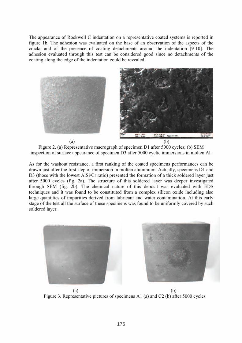
The appearance of Rockwell C indentation on a representative coated systems is reported in
figure 1b. The adhesion was evaluated on the base of an observation of the aspects of the
cracks and of the presence of coating detachments around the indentation [9-10]. The
adhesion evaluated through this test can be considered good since no detachments of the
coating along the edge of the indentation could be revealed.
(a) (b)
Figure 2. (a) Representative macrograph of specimen D1 after 5000 cycles; (b) SEM
inspection of surface appearance of specimen D3 after 5000 cyclic immersions in molten Al.
As for the washout resistance, a first ranking of the coated specimens performances can be
drawn just after the first step of immersion in molten aluminium. Actually, specimens D1 and
D3 (those with the lowest AlSi/Cr ratio) presented the formation of a thick soldered layer just
after 5000 cycles (fig. 2a). The structure of this soldered layer was deeper investigated
through SEM (fig. 2b). The chemical nature of this deposit was evaluated with EDS
techniques and it was found to be constituted from a complex silicon oxide including also
large quantities of impurities derived from lubricant and water contamination. At this early
stage of the test all the surface of these specimens was found to be uniformly covered by such
soldered layer.
(a) (b)
Figure 3. Representative pictures of specimens A1 (a) and C2 (b) after 5000 cycles
176
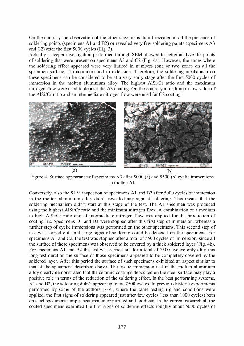
On the contrary the observation of the other specimens didn’t revealed at all the presence of
soldering points (specimens A1 and B2) or revealed very few soldering points (specimens A3
and C2) after the first 5000 cycles (Fig. 3).
Actually a deeper investigation performed through SEM allowed to better analyze the points
of soldering that were present on specimens A3 and C2 (Fig. 4a). However, the zones where
the soldering effect appeared were very limited in numbers (one or two zones on all the
specimen surface, at maximum) and in extension. Therefore, the soldering mechanism on
these specimens can be considered to be at a very early stage after the first 5000 cycles of
immersion in the molten aluminium alloy. The highest AlSi/Cr ratio and the maximum
nitrogen flow were used to deposit the A3 coating. On the contrary a medium to low value of
the AlSi/Cr ratio and an intermediate nitrogen flow were used for C2 coating.
(a) (b)
Figure 4. Surface appearance of specimens A3 after 5000 (a) and 5500 (b) cyclic immersions
in molten Al.
Conversely, also the SEM inspection of specimens A1 and B2 after 5000 cycles of immersion
in the molten aluminium alloy didn’t revealed any sign of soldering. This means that the
soldering mechanism didn’t start at this stage of the test. The A1 specimen was produced
using the highest AlSi/Cr ratio and the minimum nitrogen flow. A combination of a medium
to high AlSi/Cr ratio and of intermediate nitrogen flow was applied for the production of
coating B2. Specimens D1 and D3 were stopped after this first step of immersion, whereas a
further step of cyclic immersions was performed on the other specimens. This second step of
test was carried out until large signs of soldering could be detected on the specimens. For
specimens A3 and C2, the test was stopped after a total of 5500 cycles of immersion, since all
the surface of these specimens was observed to be covered by a thick soldered layer (Fig. 4b).
For specimens A1 and B2 the test was carried out for a total of 7500 cycles: only after this
long test duration the surface of those specimens appeared to be completely covered by the
soldered layer. After this period the surface of such specimens exhibited an aspect similar to
that of the specimens described above. The cyclic immersion test in the molten aluminium
alloy clearly demonstrated that the ceramic coatings deposited on the steel surface may play a
positive role in terms of the reduction of the soldering effect. In the best performing systems,
A1 and B2, the soldering didn’t appear up to ca. 7500 cycles. In previous historic experiments
performed by some of the authors [8-9], where the same testing rig and conditions were
applied, the first signs of soldering appeared just after few cycles (less than 1000 cycles) both
on steel specimens simply heat treated or nitrided and oxidized. In the current research all the
coated specimens exhibited the first signs of soldering effects roughly about 5000 cycles of
177
test. This means that generally the deposited coating acted very well as a barrier against the
aluminium soldering onto the specimen surface and gives a clear improvement in terms of
surface protection. Nevertheless, the coated specimens behaved with a different efficiency
according to their chemical composition. Specimens A1 and B2 (those richest in Al-Si and
with a low to medium nitrogen content) resisted for a very long time (7500 cycles), in the test
without that the aluminium adhesion on their surface had occurred. The aluminium-silicon
content in conjunction with a medium to low nitrogen content appeared to play a major role.
The best performances offered by the low nitrogen containing coating are probably due to the
fact that in such coating a large number of aluminium and silicon atoms can be left free. By
this way those free atoms are capable to form a thermally grown mixed-oxide layer in the test
environment. This layer is probably formed by a mixture of alumina and silica and acts as an
efficient barrier against the aluminium soldering. The chromium rich coatings didn’t achieved
the same positive effect, neither using a high or a low nitrogen content.
4. CONCLUSIONS
Six different coatings based on the AlSiCrN system were deposited and studied in terms of
their resistance to the washout effects produced by the molten aluminium. The coated
specimens were tested through cyclic immersion in such an aggressive environment. The
number of cycles before that the aluminium adhesion on specimens surface occurs were
recorded. The coatings where a high aluminium-silicon composition with a concurrent
medium to low nitrogen content was realized, resulted to be the more effective against
soldering. The mechanism of protection for these coating systems has to be further
investigated, but a viable explanation may be that a higher free aluminium/silicon atoms
content in the coating favors the formation of a thermally grown aluminium/silicon oxide film
in the testing conditions. This probably helps as an additional barrier against the aluminium
soldering. On the contrary, the enrichment in chromium of coating composition was found to
be not so effective in preventing aluminium soldering. Finally the nitrogen content was found
to have a slighter influence on the performance of the coating systems if compared with that
of the metallic elements content. However, it is clear that the highest is the nitrogen content
and the larger is the number of alloying atoms (Cr, Al or Si) that are bonded and, as a
consequence, can not freely form a thermally grown oxide layer as discussed above.
REFERENCES
1. F. Holler, F. Ustel, C. Mitterer and D. Heim, Proc. 5th
Int. Conf. on Tooling, Leoben
(1999), Inst. Für Metallkunde und Werkstoffprüfung, Leoben, Austria (1999), p.357.
2. D. Heim, F. Holler and C. Mitterer, Surf. And Coat. Tech. 116-119, (1999), p.530.
3. C. Mitterer, F. Holler, F. Ustel and D. Heim, Surf. and Coat. Tech. 125, (2000), p.233.
4. A. Persson, J. Bergstrom, C. Burman and S. Hogmark, Surf. and Coat. Tech. 146-147,
(2001), p.42.
5. V. Joshi, A. Srivastava and R. Shivpuri, Proc. 6th
Int. Conf. on Tooling, Karlstad (2002),
Karlstad University, Karlstad, Sweden, p.809.
6. H. Zhu, J. Guo and J. Jia, J. of Mat. Proc. Tech. 123, (2002), p.229.
7. D. Ugues, M. Rosso, M. Albertinazzi, F. Raimondi, A. Silipigni, Proc. 2nd Int. Conf. High
Tech Die Casting, Brescia, Italy (2004), p. 155.
8. D. Ugues, M. Rosso, M. Albertinazzi, Metall. Sci. and Tech., 22 No.1, (2004), Teksid,
Carmagnola (I), p. 22.
9. A. Chowdhury, D. Cameron, M. Hashmi, Surf. and Coat. Tech., 116-119, (1999), 46.
10. T. Michler, M. Grischke, K. Bewilogua, A. Hieke, Surf. and Coat. Tech., 111, (1999), 41.
178
STATUS QUO OF TRD COATING APPLICATION IN THE WORLD
Tohru Arai
Teikuro Corporation
ABSTRACT
TRD (Thermo-Reactive Deposition and Diffusion) is a carbide coating process based
on the heat treating technology. Carbide coatings with 1-20 µm are formed in a treating
reagent through chemical bonding of carbon in substrates and carbide forming
elements in the reagent. The coatings having large bonding strength can highly
improve performances of the tooling, especially used under severe working conditions.
The process has been put into practical application sine early 1970’s in the world
industries.
Key words: Salt bath immersion process, Fluidized bed process, TRD process, TD
process, Thermo-reactive deposition, diffusion
1. INTRODUCTION
TRD is a coating process of thin carbide layers that was born in the heat treatment
technology. It can be done with the heat treating equipment, the salt baths in the
ambient atmosphere or fluidized bed furnaces, by using the procedures similar to
hardening of steels. Equipment to be used is far simpler in structure, especially in case
the salt bath process, in comparison with those for other thin hard coating as CVD,
PCVD, and PVD. The coated materials are characterized by a proper combination of
the excellent surface-dependent properties inherent in the carbides and the high
strength inherent in the substrate materials. Adhesion strength of the carbide coatings
onto substrates is very large because of the metallurgical bonding. The possible
distortion problem in application of the high temperature treatments can be controlled
so as to enable the mass production of very closely tolerated parts as ± 5 µm. Thus the
process has already been employed to various tooling and components subjected to
various types of tribological damages, even accompanied with chemical attacks as
corrosion and oxidation.
1 INTERNATIONAL CONFERENCE ON HEAT TREATMENT
AND SURFACE ENGINEERING OF TOOLS AND DIES
st
Pula, Croatia 08 - 11 June, 2005,
IFHTSE 2005
179
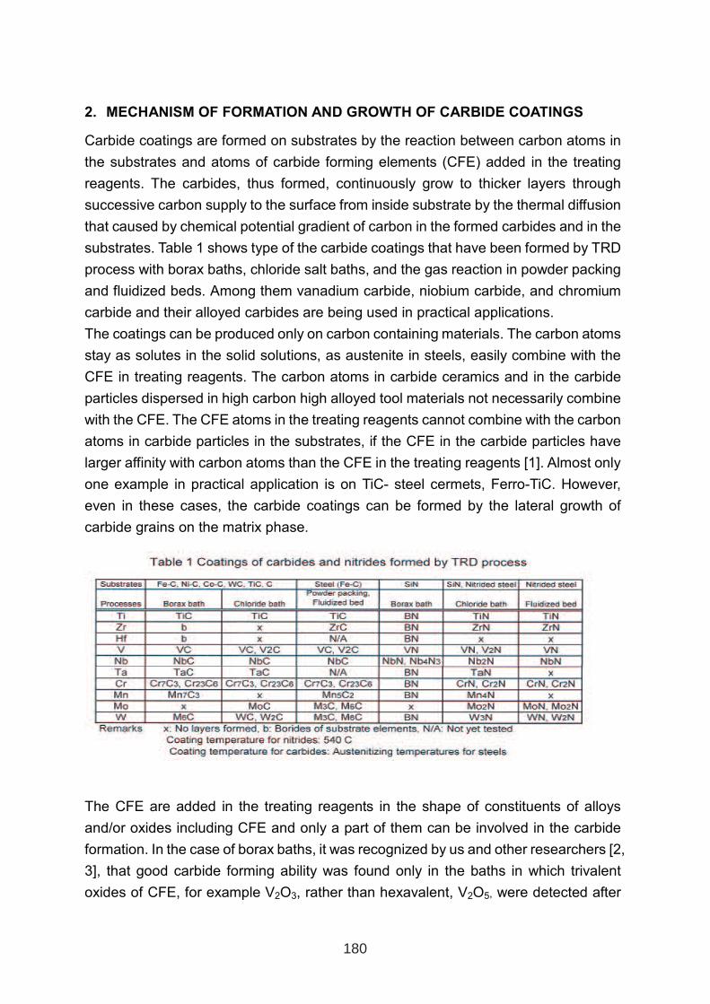
2. MECHANISM OF FORMATION AND GROWTH OF CARBIDE COATINGS
Carbide coatings are formed on substrates by the reaction between carbon atoms in
the substrates and atoms of carbide forming elements (CFE) added in the treating
reagents. The carbides, thus formed, continuously grow to thicker layers through
successive carbon supply to the surface from inside substrate by the thermal diffusion
that caused by chemical potential gradient of carbon in the formed carbides and in the
substrates. Table 1 shows type of the carbide coatings that have been formed by TRD
process with borax baths, chloride salt baths, and the gas reaction in powder packing
and fluidized beds. Among them vanadium carbide, niobium carbide, and chromium
carbide and their alloyed carbides are being used in practical applications.
The coatings can be produced only on carbon containing materials. The carbon atoms
stay as solutes in the solid solutions, as austenite in steels, easily combine with the
CFE in treating reagents. The carbon atoms in carbide ceramics and in the carbide
particles dispersed in high carbon high alloyed tool materials not necessarily combine
with the CFE. The CFE atoms in the treating reagents cannot combine with the carbon
atoms in carbide particles in the substrates, if the CFE in the carbide particles have
larger affinity with carbon atoms than the CFE in the treating reagents [1]. Almost only
one example in practical application is on TiC- steel cermets, Ferro-TiC. However,
even in these cases, the carbide coatings can be formed by the lateral growth of
carbide grains on the matrix phase.
The CFE are added in the treating reagents in the shape of constituents of alloys
and/or oxides including CFE and only a part of them can be involved in the carbide
formation. In the case of borax baths, it was recognized by us and other researchers [2,
3], that good carbide forming ability was found only in the baths in which trivalent
oxides of CFE, for example V2O3, rather than hexavalent, V2O5, were detected after
180
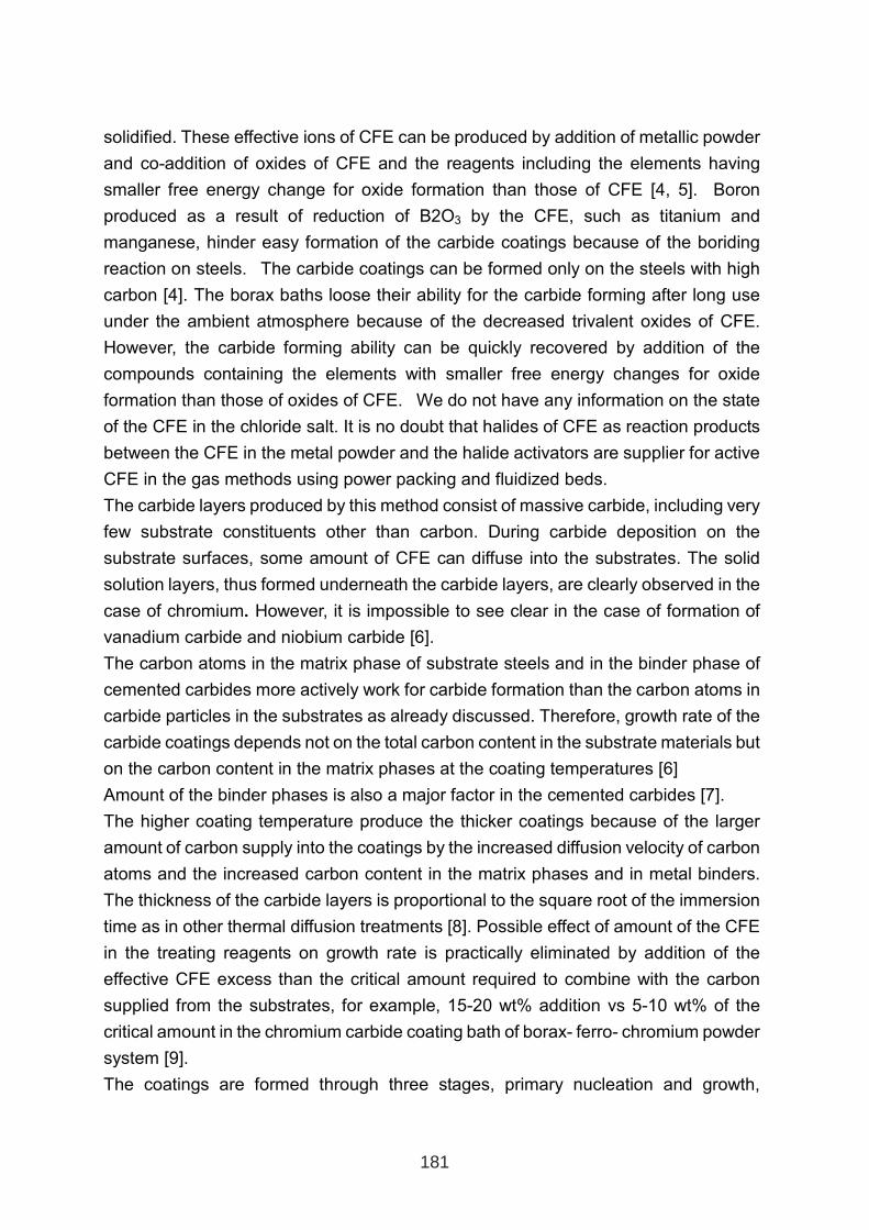
solidified. These effective ions of CFE can be produced by addition of metallic powder
and co-addition of oxides of CFE and the reagents including the elements having
smaller free energy change for oxide formation than those of CFE [4, 5]. Boron
produced as a result of reduction of B2O3 by the CFE, such as titanium and
manganese, hinder easy formation of the carbide coatings because of the boriding
reaction on steels. The carbide coatings can be formed only on the steels with high
carbon [4]. The borax baths loose their ability for the carbide forming after long use
under the ambient atmosphere because of the decreased trivalent oxides of CFE.
However, the carbide forming ability can be quickly recovered by addition of the
compounds containing the elements with smaller free energy changes for oxide
formation than those of oxides of CFE. We do not have any information on the state
of the CFE in the chloride salt. It is no doubt that halides of CFE as reaction products
between the CFE in the metal powder and the halide activators are supplier for active
CFE in the gas methods using power packing and fluidized beds.
The carbide layers produced by this method consist of massive carbide, including very
few substrate constituents other than carbon. During carbide deposition on the
substrate surfaces, some amount of CFE can diffuse into the substrates. The solid
solution layers, thus formed underneath the carbide layers, are clearly observed in the
case of chromium. However, it is impossible to see clear in the case of formation of
vanadium carbide and niobium carbide [6].
The carbon atoms in the matrix phase of substrate steels and in the binder phase of
cemented carbides more actively work for carbide formation than the carbon atoms in
carbide particles in the substrates as already discussed. Therefore, growth rate of the
carbide coatings depends not on the total carbon content in the substrate materials but
on the carbon content in the matrix phases at the coating temperatures [6]
Amount of the binder phases is also a major factor in the cemented carbides [7].
The higher coating temperature produce the thicker coatings because of the larger
amount of carbon supply into the coatings by the increased diffusion velocity of carbon
atoms and the increased carbon content in the matrix phases and in metal binders.
The thickness of the carbide layers is proportional to the square root of the immersion
time as in other thermal diffusion treatments [8]. Possible effect of amount of the CFE
in the treating reagents on growth rate is practically eliminated by addition of the
effective CFE excess than the critical amount required to combine with the carbon
supplied from the substrates, for example, 15-20 wt% addition vs 5-10 wt% of the
critical amount in the chromium carbide coating bath of borax- ferro- chromium powder
system [9].
The coatings are formed through three stages, primary nucleation and growth,
181
generation of very fine grains thereon, and growth to thicker coatings by successive
deposition of columnar grains with strong preferred orientations or equiaxed grains
with random orientations [10, 11]. The carbides can not deposit on the carbide particles
exposed at the substrate surface, if free energy change for carbide formations of CFE
in the carbide particles are smaller than those of CFE in the treating reagents since the
carbon atoms in the carbide particles are so strongly bonded with CFE [12]. Carbide
coating temperatures by use of borax bath should be higher than about 900 ºC
because of high melting point of borax. The deposition of very thin carbide coatings
was observed even at 700 ºC after long treating time by use of powder pack method
and immersion into chloride salt baths. It was found, however, that coating of
carbonitrides with enough thickness is possible onto pre-nitrided steels at the
temperatures for high temperature tempering for steels [13] and the process has been
already put into practical applications [14].
3. COATING PROCEDURES OF SALT BATH IMMERSION PROCESESS
The high temperature salt bath TRD coating is performed in the borax baths at
900-1050 ºC. The immersion time needed for making 4 to 7 µm coating on steels range
from 1 to 4 hours, but 2 to 10 hours are added, depending on the relative volume of salt
and parts, to wait for recover of the salt temperature down by charging of cold parts.
The parts to be coated usually preheated preliminary but the parts are gradually
heated up to the coating temperature in the TRD baths during the temperature
recovery. Air cooling, oil quenching, and salt bath quenching are usually applied to
harden the substrates of tooling and most wear resisting parts. Quenching after
re-austenitizing is also employed in applications to small machine components in a
large number and to high speed steels. Attached salt on the treated parts is removed
by immersing in hot boiling water for a few hours with minor mechanical procedures,
as long as the bath condition is well controlled.
Fluidizing bed TRD can be done with the furnaces conventionally used for heat
treatment of steels. Ferro-alloys or pure metals of CFE are mixed in aluminum oxide
powder as fluidizing powders and gas or pellets of halides are also added in the beds
to make the halide gas of CFE [15]. Hardening of the substrates is achieved during
cooling down in a bell-jar type cooling equipment attached at the top of a reaction
chamber.
182
4. PROPRTIES OF COATD MATERIALS
The carbide coatings made by TRD process are very dense and have smooth surface
as long as the substrates were preliminarily finished smoothly, thus they have
excellent tribological properties inherent in carbides. Because of their nucleation and
growth mechanism, and the oxide scale resolving ability of borax salts, the bonding
strength of TRD coatings to the substrates is much larger steadily than those by PVD,
regardless of type of the substrate materials [4-6, 8, 16, 17].
5. PRACTICAL APPLICATION
TRD coatings work well, regardless of type of the coated carbide, VC, NbC, Cr7C3 and
Cr23C6, and (V,Nb)C, in almost any types of applications requiring high resistance to
wear, galling, corrosion and oxidation (only with Cr7C3 and Cr23C6). Because of their
high bonding strength to the substrates, applications are dominant to the tooling used
under very severe working conditions, as typically stamping high tensile strength
steels, stainless steels and heavy gauged steels. Marketing of the standard punches
from 30 years ago in Japan, still increasing their production, is a typical example of
TRD coating applications to the parts with very tight dimensional tolerances.
Application fields of TRD coating can be classified into major three groups.
• Production tooling as dies and molds, and various types of wear parts used in
material processing – stamping, forging, casting, powder compacting, plastics
molding, rubber molding, glass molding, cutting and cutting-off
• Various type of wear parts used in material processing– stamping, forging,
casting, powder compacting, plastics molding, rubber molding, glass molding,
cutting and cutting-off, welding, assembling, painting, spinning and looming,
printing, food making etc,
• Components of various machines and equipment– fasteners, pneumatic
machines, automobile, etc.
In numbers, the largest application is or was for machine components made of
structural steels including automotive components. Applications started in Japan, in
1970 by the high temperature salt bath process, in 1990 by the high temperature
fluidized bed process, and in 1990 by the low temperature salt bath process and the
countries where TRD coating is in practical operations count more than 16 as far as we
know. Japan, Korea, USA, Canada, and South Africa are mostly benefited by TRD
currently. TRD applications look in the secondary large growth period since the end of
1990’s in the world.
183
TRD is an only one technology among heat treating fields can be equal to or can outperform
other deposition processes as CVD and PVD in performances of coated components,
especially used for tribological requirements under very severe working condition. TRD,
especially the salt bath process, features less expensive investment cost inherent in heat
treatment, larger flexibility in selection of the cooling methods, larger possibility of the mixed
loading with different substrate materials, different coating times, different quenching methods,
and larger possibility in substrate selection. Borax based baths are non-corrosive, no fume
and cause no severe toxic problem. There is no need for any sophisticated pre-cleaning
equipment, because of the nature of molten borax: high dissolution power for the oxide scale
resolving ability of borax. However, sophisticated knowledge and capability of well-engineered
procedures based on knowledge and experience on heat treating of steels are indispensable
for ensuring good quality of the coated parts relating to dimension and substrate hardness
unlike the normal heat treating and CVD, PVD.
REFERENCES
1. T. Arai: Thin Solid Films, 229(1993) p.171
2. S. B. Fazluddin, A. Koursaris, et al.: Proc. of 6th Int. Conf. on Surface Modification
Technologies, TMS (1993), p.46
3. H.C. Child et al.: Heat Treatment Conf. Inst. Metals, London, (1984)
4. T. Arai, H. Fujita, et al.: ASM Int., Metals/Materials Technology Series, (1985), 8512-008
5. T. Arai, H. Fujita, et al.:Surface Modifications and Coatings; ASM’s Surface Treating and
Coating Div., (1985), p. 311
6. T. Arai: J. Heat Treating, Vol.1 (1979), p.1�
7. T. Arai:Proc. Interfinish 92, Sao Paulo, (1992), p.671
8. T. Arai, S. Harper: Metals Handbook, Vol.4: Heat treating, ASM Int. (1991), p.448
9. T. Arai: Surface Modification Technologies III, TMS, (1990), p.58�
10. T. Arai: Thin Solid Films, 249 (1994), p. 5�
11. T. Arai: S. Moriyama, Thin Solid Films, 259(1995), p. 174
12. T. Arai: Thin Solid Films, 229(1985), p. 171
13. T. Arai, H. Fujita et al: Proc. 6thInt. Cong. Heat Treatm. of Mat., Chicago, (1988), p. 49
14. Y. Ohta, T. Arai et al: Congress book of 8th Int. Cong. Heat Treatment of Materials, Kyoto,
(1992), p.503
15. K. Nakanishi, T. Arai: Congress book of 8th Int. Cong. Heat Treatment of Materials, (1992),
Kyoto, p. 507
16. T. Arai, H. Fujita et al.: Proc. Material ’87, Inst. Metals, London, (1997), p.29
17. T. Arai, H. Fujita et al.: Thin Solid Films, 154(1987), p. 387
184
6. USEFULNESS AS A SURFACE MODIFICATION TECHNOLOGY
IMPROVEMENT OF HOT WORK STEEL WEAR RESISTANCE BY
PLASMA NITRIDING AND PVD COATINGS
Dobrzański L.A.1, Polok M.
1, Adamiak M.
1, Faga M. G.
2
1Silesian University of Technology, Institute of Engineering Materials and Biomaterials,
Konarskiego 18a Str., Gliwice, Poland, email: [email protected] Strada delle Cacce 73, 10135 Torino, Italy
ABSTARCT
The paper presents test results of the mechanical and tribological properties of the CrN and
TiN/(Ti,Al)N anti-wear PVD coatings put down onto substrate from the plasma nitrided
X37CrMoV5-1 type hot work steel. The best adhesion and abrasion wear resistance are
characteristic of the TiN/(Ti,Al)N multilayer coating. The wear resistance was tested of the
nitrided hot work tool steel with the PVD coatings put down, at the room temperature and at
the temperature of 500ºC. These test results correspond with the very good adhesion of the
coating to the substrate material and its high hardness. It was revealed that the coating damage
mechanism in the scratch test commences in all cases with the widespread coating spalling at
the edge of the scratch being made, and next develops depending on the coating type and
location of the originated defects.
Keywords: Hot work steel, plasma nitriding, PVD coatings, pin-on-disk, wear resistance
1. INTRODUCTION
Metalworking industries have shown interest to improve tools used in hot – working process:
metal die casting, hot extrusion and hot forging [1,2]. Service life of tools made from hot
work steels (among others forging tools, moulds for light metals pressure die casting, rolls for
copper hot rolling , mandrels, tools for hot cutting) for the sake their prices is an extremely
essential thing in the context of production costs lowering and optimization. One of the most
frequently applied method of tool life improvement is PVD technique [3,4].
Thin hard coatings are today employed in vast number of applications for reducing friction
and wear of tools and mechanical components. PVD coatings have also been used for selected
hot-working processes [5,6]. PVD TiN/(Ti,Al)N and CrN coatings have become important for
several industrial applications at elevated temperature. However, application of PVD hard
coatings to the substrate cannot guarantee the optimal tribological performance. The best
results in protection of tools were obtained with duplex treatment procedure. Duplex
treatment for tribological applications is a combined of termochemical treatment of the tool
1 INTERNATIONAL CONFERENCE ON HEAT TREATMENT
AND SURFACE ENGINEERING OF TOOLS AND DIES
st
Pula, Croatia 08 - 11 June, 2005,
IFHTSE 2005
185
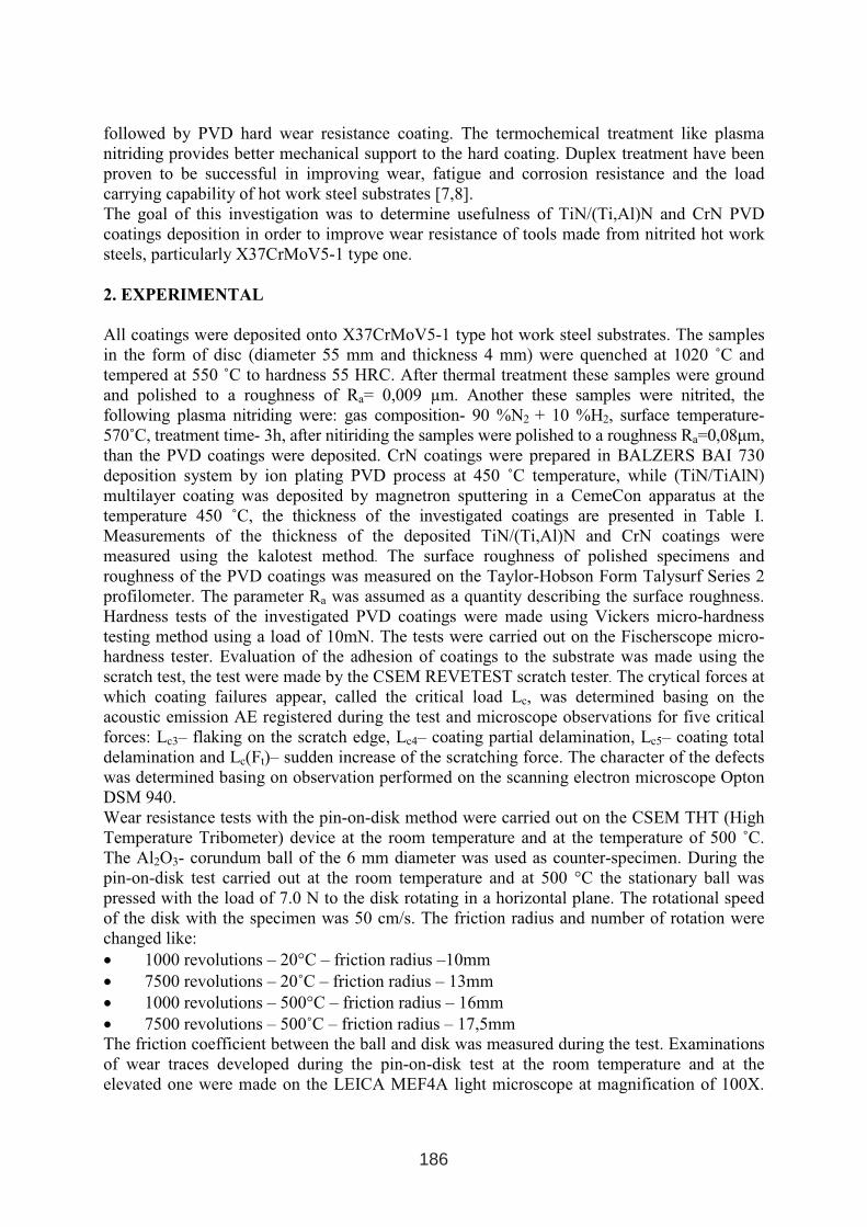
followed by PVD hard wear resistance coating. The termochemical treatment like plasma
nitriding provides better mechanical support to the hard coating. Duplex treatment have been
proven to be successful in improving wear, fatigue and corrosion resistance and the load
carrying capability of hot work steel substrates [7,8].
The goal of this investigation was to determine usefulness of TiN/(Ti,Al)N and CrN PVD
coatings deposition in order to improve wear resistance of tools made from nitrited hot work
steels, particularly X37CrMoV5-1 type one.
2. EXPERIMENTAL
All coatings were deposited onto X37CrMoV5-1 type hot work steel substrates. The samples
in the form of disc (diameter 55 mm and thickness 4 mm) were quenched at 1020 ˚C and
tempered at 550 ˚C to hardness 55 HRC. After thermal treatment these samples were ground
and polished to a roughness of Ra= 0,009 µm. Another these samples were nitrited, the
following plasma nitriding were: gas composition- 90 %N2 + 10 %H2, surface temperature-
570˚C, treatment time- 3h, after nitiriding the samples were polished to a roughness Ra=0,08µm,
than the PVD coatings were deposited. CrN coatings were prepared in BALZERS BAI 730
deposition system by ion plating PVD process at 450 ˚C temperature, while (TiN/TiAlN)
multilayer coating was deposited by magnetron sputtering in a CemeCon apparatus at the
temperature 450 ˚C, the thickness of the investigated coatings are presented in Table I.
Measurements of the thickness of the deposited TiN/(Ti,Al)N and CrN coatings were
measured using the kalotest method. The surface roughness of polished specimens and
roughness of the PVD coatings was measured on the Taylor-Hobson Form Talysurf Series 2
profilometer. The parameter Ra was assumed as a quantity describing the surface roughness.
Hardness tests of the investigated PVD coatings were made using Vickers micro-hardness
testing method using a load of 10mN. The tests were carried out on the Fischerscope micro-
hardness tester. Evaluation of the adhesion of coatings to the substrate was made using the
scratch test, the test were made by the CSEM REVETEST scratch tester. The crytical forces at
which coating failures appear, called the critical load Lc, was determined basing on the
acoustic emission AE registered during the test and microscope observations for five critical
forces: Lc3– flaking on the scratch edge, Lc4– coating partial delamination, Lc5– coating total
delamination and Lc(Ft)– sudden increase of the scratching force. The character of the defects
was determined basing on observation performed on the scanning electron microscope Opton
DSM 940.
Wear resistance tests with the pin-on-disk method were carried out on the CSEM THT (High
Temperature Tribometer) device at the room temperature and at the temperature of 500 ˚C.
The Al2O3- corundum ball of the 6 mm diameter was used as counter-specimen. During the
pin-on-disk test carried out at the room temperature and at 500 °C the stationary ball was
pressed with the load of 7.0 N to the disk rotating in a horizontal plane. The rotational speed
of the disk with the specimen was 50 cm/s. The friction radius and number of rotation were
changed like:
• 1000 revolutions – 20°C – friction radius –10mm
• 7500 revolutions – 20˚C – friction radius – 13mm
• 1000 revolutions – 500°C – friction radius – 16mm
• 7500 revolutions – 500˚C – friction radius – 17,5mm
The friction coefficient between the ball and disk was measured during the test. Examinations
of wear traces developed during the pin-on-disk test at the room temperature and at the
elevated one were made on the LEICA MEF4A light microscope at magnification of 100X.
186
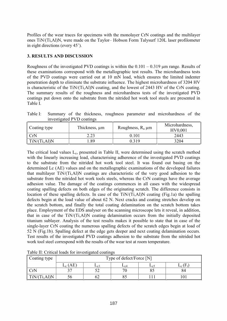
Profiles of the wear traces for specimens with the monolayer CrN coatings and the multilayer
ones TiN/(Ti,Al)N, were made on the Taylor– Hobson Form Talysurf 120L laser profilometer
in eight directions (every 45˚).
3. RESULTS AND DISCUSSION
Roughness of the investigated PVD coatings is within the 0.101 – 0.319 µm range. Results of
these examinations correspond with the metallographic test results. The microhardness tests
of the PVD coatings were carried out at 10 mN load, which ensures the limited indenter
penetration depth to eliminate the substrate influence. The highest microhardness of 3204 HV
is characteristic of the TiN/(Ti,Al)N coating, and the lowest of 2443 HV of the CrN coating.
The summary results of the roughness and microhardness tests of the investigated PVD
coatings put down onto the substrate from the nitrided hot work tool steels are presented in
Table I.
Table I: Summary of the thickness, roughness parameter and microhardness of the
investigated PVD coatings
Coating type Thickness, µm Roughness, Ra µmMicrohardness,
HV0,001
CrN 2.23 0.101 2443
TiN/(Ti,Al)N 1.89 0.319 3204
The critical load values Lc, presented in Table II, were determined using the scratch method
with the linearly increasing load, characterising adherence of the investigated PVD coatings
to the substrate from the nitrided hot work tool steel. It was found out basing on the
determined Lc (AE) values and on the metallographic examinations of the developed failures
that multilayer TiN/(Ti,Al)N coatings are characteristic of the very good adhesion to the
substrate from the nitrided hot work tools steels, whereas the CrN coatings have the average
adhesion value. The damage of the coatings commences in all cases with the widespread
coating spalling defects on both edges of the originating scratch. The difference consists in
location of these spalling defects. In case of the TiN/(Ti,Al)N coating (Fig.1a) the spalling
defects begin at the load value of about 62 N. Next cracks and coating stretches develop on
the scratch bottom, and finally the total coating delamination on the scratch bottom takes
place. Employment of the EDS analyser on the scanning microscope lets it reveal, in addition,
that in case of the TiN/(Ti,Al)N coating delamination occurs from the initially deposited
titanium sublayer. Analysis of the test results makes it possible to state that in case of the
single-layer CrN coating the numerous spalling defects of the scratch edges begin at load of
52 N (Fig.1b). Spalling defect at the edge gets deeper and next coating delamination occurs.
Test results of the investigated PVD coatings adhesion to the substrate from the nitrided hot
work tool steel correspond with the results of the wear test at room temperature.
Table II: Critical loads for investigated coatings
Type of defect/Force [N]Coating type
Lc (AE) Lc3 Lc4 Lc5 Lc (Ft)
CrN 37 52 70 85 84
TiN/(Ti,Al)N 56 62 85 111 101
187
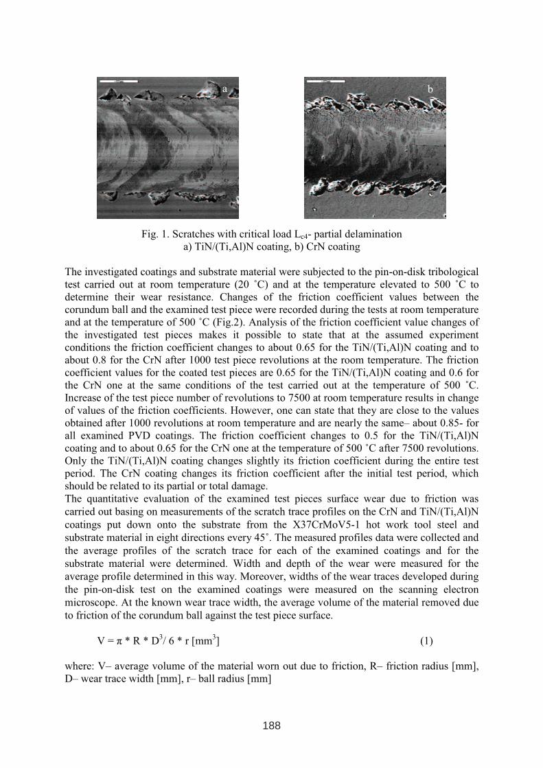
Fig. 1. Scratches with critical load Lc4- partial delamination
a) TiN/(Ti,Al)N coating, b) CrN coating
The investigated coatings and substrate material were subjected to the pin-on-disk tribological
test carried out at room temperature (20 ˚C) and at the temperature elevated to 500 ˚C to
determine their wear resistance. Changes of the friction coefficient values between the
corundum ball and the examined test piece were recorded during the tests at room temperature
and at the temperature of 500 ˚C (Fig.2). Analysis of the friction coefficient value changes of
the investigated test pieces makes it possible to state that at the assumed experiment
conditions the friction coefficient changes to about 0.65 for the TiN/(Ti,Al)N coating and to
about 0.8 for the CrN after 1000 test piece revolutions at the room temperature. The friction
coefficient values for the coated test pieces are 0.65 for the TiN/(Ti,Al)N coating and 0.6 for
the CrN one at the same conditions of the test carried out at the temperature of 500 ˚C.
Increase of the test piece number of revolutions to 7500 at room temperature results in change
of values of the friction coefficients. However, one can state that they are close to the values
obtained after 1000 revolutions at room temperature and are nearly the same– about 0.85- for
all examined PVD coatings. The friction coefficient changes to 0.5 for the TiN/(Ti,Al)N
coating and to about 0.65 for the CrN one at the temperature of 500 ˚C after 7500 revolutions.
Only the TiN/(Ti,Al)N coating changes slightly its friction coefficient during the entire test
period. The CrN coating changes its friction coefficient after the initial test period, which
should be related to its partial or total damage.
The quantitative evaluation of the examined test pieces surface wear due to friction was
carried out basing on measurements of the scratch trace profiles on the CrN and TiN/(Ti,Al)N
coatings put down onto the substrate from the X37CrMoV5-1 hot work tool steel and
substrate material in eight directions every 45˚. The measured profiles data were collected and
the average profiles of the scratch trace for each of the examined coatings and for the
substrate material were determined. Width and depth of the wear were measured for the
average profile determined in this way. Moreover, widths of the wear traces developed during
the pin-on-disk test on the examined coatings were measured on the scanning electron
microscope. At the known wear trace width, the average volume of the material removed due
to friction of the corundum ball against the test piece surface.
V = π * R * D3/ 6 * r [mm
3] (1)
where: V– average volume of the material worn out due to friction, R– friction radius [mm],
D– wear trace width [mm], r– ball radius [mm]
ba
188

One can state, basing on the completed wear measurement results of the PVD coatings on the
X37CrMoV5-1 nitrided hot work steel (Fig. 2), that during the tests at the temperature of
20˚C for both 1000 and 7500 revolutions the highest abrasion wear resistance was
characteristic of the TiN/(Ti,Al)N coating. Change of the number of revolutions from 1000 to
7500 causes the wear to increase threefold. Wear test results for the investigated coatings at
room temperature correspond with the coating adhesion to the substrate material test results
and hardness test results. The very good adherence of the TiN/(Ti,Al)N coating and its high
hardness– 3204.7 HV0.01 result in its high abrasion wear resistance at room temperature. The
low abrasion wear resistance of the CrN coating results from its poor adherence to the
substrate and low hardness. It was found out comparing the wear of the examined coatings
during the pin-on-disk test at room temperature and at 500 ˚C that temperature growth causes
the nearly tenfold wear increase, regardless of the number of revolutions made by the test
piece. The TiN/(Ti,Al)N coating proved to perform well in the test conditions for 1000 and
7500 revolutions. Therefore, one can state that both at the room and elevated temperatures the
multilayer TiN/(Ti,Al)N coating is characteristic of the best wear resistance, with the single
layer CrN coating taking the second place. In case of the TiN/(Ti,Al)N coating deposited onto
the X37CrMoV5-1 nitrided hot work steel the very good adherence was revealed to the
substrate material compared to the CrN coating. Evaluation results of the volume of material
removed during the pin-on-disk test correspond with the wear trace width measurements
made by observations carried out on the scanning electron microscope.
The wear trace width values measured on the scanning electron microscope grow with the test
temperature, regardless of the number of revolutions made by the test piece.
CrN
TiN
/(Ti,A
l)N
CrN
TiN
/(Ti,A
l)N
1000
75000
0 ,1
0 ,2
0 ,3
0 ,4
0 ,5
0 ,6
0 ,7
0 ,8
V,
mm
3
Fig. 2. Comparison of volume of materials removed during tribological wear
4. CONCLUSIONS
The goal of this investigation was to determine usefulness of CrN, TiN/(Ti,Al)N PVD
coatings deposition in order to improve wear resistance of tools made from nitrited hot work
steels, particularly X37CrMoV5-1 type one. Mechanical properties like microhardness of the
PVD coatings is changed in the range from 2443 HV in the case of CrN coating to 3204
HV0,01 in the case of TiN/(Ti,Al)N ones. Adhesion of monolayer CrN and multilayer
TiN/(Ti, Al)N coatings to the substrate from the nitrited X37CrMoV5-1 hot work tool steel
changes significantly depending from the assumed criterion; however the general trend
20°C
500°C
revolutions
189
remains. The TiN/(Ti,Al)N coating has the best adhesion, and the CrN coating demonstrates
the worst adhesion. Measurement of the friction coefficient during the pin-on-disk test makes
it possible to note that the TiN/(Ti,Al)N coating has the lowest friction coefficient both at the
room temperature and at the elevated one. Moreover, one can state that the friction coefficient
changes with the development of the coating failure process and after its total removal the
values obtained were typical for the substrate material. The TiN/(Ti,Al)N coating has the
highest wear resistance at the room temperature and the elevated temperature 500 °C. In case
of the TiN/(Ti,Al)N coating deposited onto the X37CrMoV5-1 nitrided hot work steel the
very good adherence was revealed to the substrate material compared to the CrN coating.
Taking into account results of measurements one can state that the lowest wear at certain
conditions in both room and elevated temperatures shows TiN/(Ti,Al)N monolayer coating
what can be connected with their good adherence to the substrate materials as well as the
highest hardness.
REFERENCES
1. B. Navinšek, P. Panjan, F. Gorenjak, Surface and Coatings Technology, 137(2001), 255-
264
2. L.A Dobrzański, M. Polok, M. Adamiak, Journal of Materials Processing Technology,
155-156(2004), 1995-2001
3. M. Polok, Structure and properties of TiN, CrN and TiN/(Ti,Al)N PVD coatings deposited
onto heat treated and plasma nitrided hot work steel- PhD thesis in progress
4. J.W. Seok, N.M. Jadeed, R.Y. Lin, Surface and Coatings Technology, 138(2001), 14-22
5. A.E. Zeghni, M.S.J. Hashmi, Journal of Materials Processing Technology, 155-156(2004),
1918-1922
6. A. Bloynce, Y. Sun, X.Y. Li, Heat treatment of metal, 2(1999), 37-41
7. P. Panjan, M. Čekada, R. Kirn, M. Soković, Surface and Coatings Technology, 180-
181(2004), 561-565
8. J.C.A. Batista, C. Godoy, V.T.L. Buono, A. Matthews, Materials Science and Engineering
A336(2002), 39-51
190
IMPROVEMENT IN GALLING PERFORMANCE THROUGH
SURFACE ENGINEERING
B. Podgornik1, J. Vižintin
1, S. Hogmark
2
1University of Ljubljana, CTD, Ljubljana, Slovenia
2Uppsala University, Tribomaterials group, Uppsala, Sweden
ABSTRACT
The aim of the present work was to investigate and compare different surface engineering
techniques in terms of galling properties of forming tool steel when sliding against different
work materials. The surface engineering techniques included were different grades of
polishing, plasma nitriding and different hard coatings, all applied to cold work tool steel,
respectively.
Investigation results indicate that the galling tendency can be greatly reduced by proper
polishing of the tool surface. If polished after treatment, plasma nitrided surface will provide
further improvement in friction and wear properties of the tool steel and especially for
aluminium and titanium alloys reduce the galling tendency. On the other hand, coating
selection for improved galling performance of coated forming tool steel greatly depends on
the type of work material. In the case of stainless steel, carbon-based coatings provide the best
protection against the work material transfer, while forming of aluminium and titanium based
alloys, requires nitride type coatings.
Keywords: forming tools, surface engineering, friction, galling
1 INTERNATIONAL CONFERENCE ON HEAT TREATMENT
AND SURFACE ENGINEERING OF TOOLS AND DIES
st
Pula, Croatia 08 - 11 June, 2005,
IFHTSE 2005
191
1. INTRODUCTION
The major obstacles to generate smooth surfaces during forming are smudge, orange peel and
galling, with galling being the dominant cause for tool failure in sheet forming processes for
austenitic stainless steel, aluminium-, nickel- and titanium based alloys [1]. To some extent
galling can be hindered by modification of the tool surface [2]. One way of modifying the
surface, already effectively used in the forming industry, is thermo-chemical surface treatment
of the tool, i.e. hardening, nitriding, carbonitriding, etc. [3,4]. In the last decade hard PVD and
CVD coatings have started to successfully compete with the traditional thermo-chemical
treatments, especially in terms of abrasive wear resistance [5]. However, although hard and
corrosion-resistant coatings show high hardness and are frequently used to protect and
enhance the lifetime of cutting tools, the majority of the industrial forming tools is still
uncoated. Beside a complex shape that often makes the forming tools difficult to coat, the
tribological loads of the forming tools are greatly influenced by the work material.
Furthermore, with a relatively high friction coefficient and a high tendency to galling when in
contact with soft metals [4,6], commercial hard ceramic coatings used in cutting tool
applications certainly do not represent the very best solution for improving performance of
forming tools. However, in the last couple of years, tremendous progress has been seen in the
field of coating deposition and design of coatings with excellent tribological properties [7-9].
The aim of the present investigation was to compare different hard coatings in terms of
galling properties when applied on forming tool steel and slid against austenitic stainless steel,
aluminium and titanium alloy, respectively. Tribological evaluation, carried out in a load-
scanning test rig included PVD deposited TiN, TiB2, TaC and DLC coatings.
2. EXPERIMENTAL
The substrate material used in this investigation was a powder metallurgy cold work tool
steel, VANADIS 4, from Uddeholm Tooling AB, Sweden. It has a nominal chemical
composition (wt. %) of 1.5 C, 1.0 Si, 0.4 Mn, 8.0 Cr, 1.5 Mo, 4.0 V. The cylindrical test rods
(φ 10mm, 100mm long) were hardened and tempered to 62 HRC, and ground to an average Ra
value of ≈ 0.25 µm.
After sputter cleaning specimens were coated with four different PVD coatings using
commercial PVD processes; TiN, TiB2, TaC and DLC, respectively. Process parameters and
properties of the coatings used in this investigation are listed in ref. [10]. While the refractory
hard coatings of TiN, TiB2 and TaC were of a monolayer type, the DLC coatings showed a
multilayer structure of WC and a-C:H. Nevertheless, all coatings had the same thickness of
about 2 µm.
Galling properties of a coated VANADIS 4 steel were investigated in the load-scanning test
rig and compared to uncoated hardened or plasma nitrided VANADIS 4 steel (Table 1).
Plasma nitriding was performed at low nitrogen content (95%H2-5%N2), which led to a
compound-free diffusion zone with a thickness of ~55 µm. The test configuration, which
involves two crossed cylinders that are forced to slide against each other under a constant
speed, allows the normal load to be gradually increased during the forward stroke and
correspondingly decreased during reverse stroke [11]. Thus, each point along the contact path
of both specimens will experience a unique load and display a unique tribological history after
test completion.
For the purpose of this investigation, where the ability of investigated materials and coatings to
prevent transfer of work material to the tool surface was evaluated, the load-scanner test rig was
set to a single, forward stroke mode. The normal load was gradually increased from 100 to 1300
192
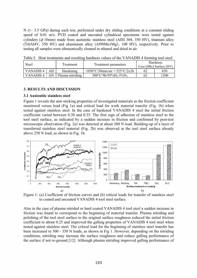
N (1– 3.5 GPa) during each test, performed under dry sliding conditions at a constant sliding
speed of 0.01 m/s. PVD coated and uncoated cylindrical specimens were tested against
cylinders (φ 10mm) made from austenitic stainless steel (AISI 304, 350 HV), titanium alloy
(Ti6Al4V, 350 HV) and aluminium alloy (Al98Mn1Mg1, 100 HV), respectively. Prior to
testing all samples were ultrasonically cleaned in ethanol and dried in air.
Table I: Heat treatments and resulting hardness values of the VANADIS 4 forming tool steel
Steel Treatment Treatment parameters Hardness
Core [HRc] Surface [HV]
VANADIS 4 AH Hardening 1050°C/30min/air + 525°C/2x2h 62 850
VANADIS 4 AN Plasma nitriding 500°C/9h/95%H2-5%N2 62 1200
3. RESULTS AND DISCUSSION
3.1 Austenitic stainless steel
Figure 1 reveals the anti-sticking properties of investigated materials as the friction coefficient
monitored versus load (Fig 1a) and critical load for work material transfer (Fig. 1b) when
tested against stainless steel. In the case of hardened VANADIS 4 steel the initial friction
coefficient varied between 0.30 and 0.35. The first sign of adhesion of stainless steel to the
tool steel surface, as indicated by a sudden increase in friction and confirmed by post-test
microscopic observation (Fig. 2a) was detected at about 200 N load. Building-up of a layer of
transferred stainless steel material (Fig. 2b) was observed at the tool steel surface already
above 250 N load, as shown in Fig. 1b.
0
0.1
0.2
0.3
0.4
0.5
0.6
0.7
0.8
0 200 400 600 800 1000 1200 1400
Normal load [N]
Co
eff
icie
nto
ffr
ictio
n
TiB2 Vanadis 4
hardened
TiN
TaCDLC
Vanadis 4
nitrided
0
200
400
600
800
1000
1200
1400
Hardening Nitriding TiN TiB2 TaC DLC
Surface tratment or coating
Cri
tic
allo
ad
[N]
Lc1
Lc2
a) b)
Figure 1: (a) Coefficient of friction curves and (b) critical loads for transfer of stainless steel
to coated and uncoated VANADIS 4 tool steel surface.
Also in the case of plasma nitrided or hard coated VANADIS 4 tool steel a sudden increase in
friction was found to correspond to the beginning of material transfer. Plasma nitriding and
polishing of the tool steel surface to the original surface roughness reduced the initial friction
coefficient to about 0.25 and improved the galling properties of VANADIS 4 tool steel when
tested against stainless steel. The critical load for the beginning of stainless steel transfer has
been increased to 300 - 350 N loads, as shown in Fig 1. However, depending on the nitriding
conditions, nitriding may increase the surface roughness and reduce galling performance of
the surface if not re-ground [12]. Although plasma nitriding improved galling performance of
193
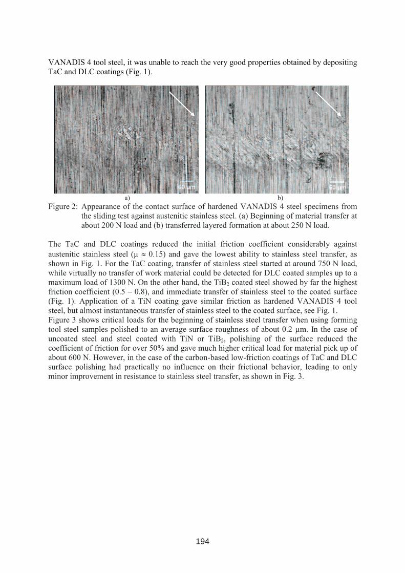
VANADIS 4 tool steel, it was unable to reach the very good properties obtained by depositing
TaC and DLC coatings (Fig. 1).
a) b)
Figure 2: Appearance of the contact surface of hardened VANADIS 4 steel specimens from
the sliding test against austenitic stainless steel. (a) Beginning of material transfer at
about 200 N load and (b) transferred layered formation at about 250 N load.
The TaC and DLC coatings reduced the initial friction coefficient considerably against
austenitic stainless steel (µ ≈ 0.15) and gave the lowest ability to stainless steel transfer, as
shown in Fig. 1. For the TaC coating, transfer of stainless steel started at around 750 N load,
while virtually no transfer of work material could be detected for DLC coated samples up to a
maximum load of 1300 N. On the other hand, the TiB2 coated steel showed by far the highest
friction coefficient (0.5 – 0.8), and immediate transfer of stainless steel to the coated surface
(Fig. 1). Application of a TiN coating gave similar friction as hardened VANADIS 4 tool
steel, but almost instantaneous transfer of stainless steel to the coated surface, see Fig. 1.
Figure 3 shows critical loads for the beginning of stainless steel transfer when using forming
tool steel samples polished to an average surface roughness of about 0.2 µm. In the case of
uncoated steel and steel coated with TiN or TiB2, polishing of the surface reduced the
coefficient of friction for over 50% and gave much higher critical load for material pick up of
about 600 N. However, in the case of the carbon-based low-friction coatings of TaC and DLC
surface polishing had practically no influence on their frictional behavior, leading to only
minor improvement in resistance to stainless steel transfer, as shown in Fig. 3.
194
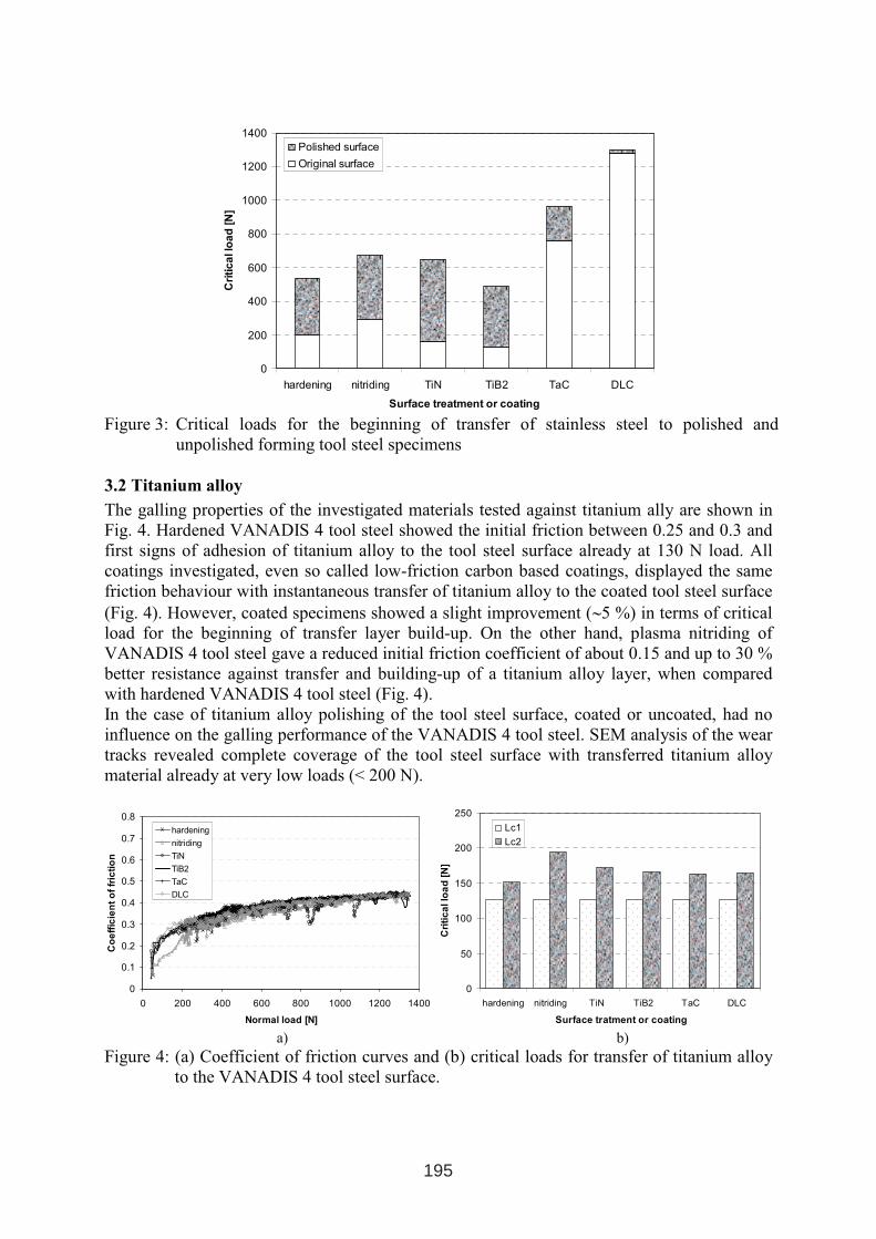
0
200
400
600
800
1000
1200
1400
hardening nitriding TiN TiB2 TaC DLC
Surface treatment or coating
Cri
tica
llo
ad
[N]
Polished surface
Original surface
Figure 3: Critical loads for the beginning of transfer of stainless steel to polished and
unpolished forming tool steel specimens
3.2 Titanium alloy
The galling properties of the investigated materials tested against titanium ally are shown in
Fig. 4. Hardened VANADIS 4 tool steel showed the initial friction between 0.25 and 0.3 and
first signs of adhesion of titanium alloy to the tool steel surface already at 130 N load. All
coatings investigated, even so called low-friction carbon based coatings, displayed the same
friction behaviour with instantaneous transfer of titanium alloy to the coated tool steel surface
(Fig. 4). However, coated specimens showed a slight improvement (∼5 %) in terms of critical
load for the beginning of transfer layer build-up. On the other hand, plasma nitriding of
VANADIS 4 tool steel gave a reduced initial friction coefficient of about 0.15 and up to 30 %
better resistance against transfer and building-up of a titanium alloy layer, when compared
with hardened VANADIS 4 tool steel (Fig. 4).
In the case of titanium alloy polishing of the tool steel surface, coated or uncoated, had no
influence on the galling performance of the VANADIS 4 tool steel. SEM analysis of the wear
tracks revealed complete coverage of the tool steel surface with transferred titanium alloy
material already at very low loads (< 200 N).
0
0.1
0.2
0.3
0.4
0.5
0.6
0.7
0.8
0 200 400 600 800 1000 1200 1400
Normal load [N]
Co
eff
icie
nt
of
fric
tio
n
hardening
nitriding
TiN
TiB2
TaC
DLC
0
50
100
150
200
250
hardening nitriding TiN TiB2 TaC DLC
Surface tratment or coating
Cri
tic
allo
ad
[N]
Lc1
Lc2
a) b)
Figure 4: (a) Coefficient of friction curves and (b) critical loads for transfer of titanium alloy
to the VANADIS 4 tool steel surface.
195
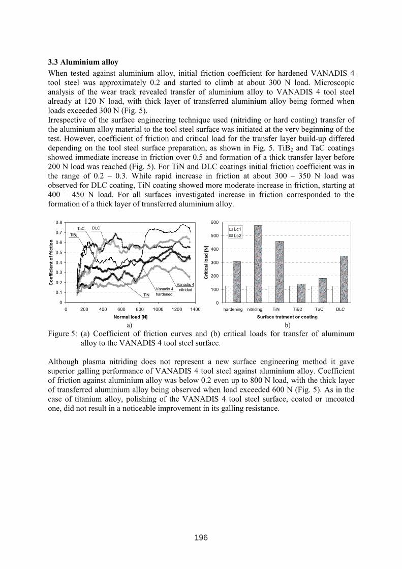
3.3 Aluminium alloy
When tested against aluminium alloy, initial friction coefficient for hardened VANADIS 4
tool steel was approximately 0.2 and started to climb at about 300 N load. Microscopic
analysis of the wear track revealed transfer of aluminium alloy to VANADIS 4 tool steel
already at 120 N load, with thick layer of transferred aluminium alloy being formed when
loads exceeded 300 N (Fig. 5).
Irrespective of the surface engineering technique used (nitriding or hard coating) transfer of
the aluminium alloy material to the tool steel surface was initiated at the very beginning of the
test. However, coefficient of friction and critical load for the transfer layer build-up differed
depending on the tool steel surface preparation, as shown in Fig. 5. TiB2 and TaC coatings
showed immediate increase in friction over 0.5 and formation of a thick transfer layer before
200 N load was reached (Fig. 5). For TiN and DLC coatings initial friction coefficient was in
the range of 0.2 – 0.3. While rapid increase in friction at about 300 – 350 N load was
observed for DLC coating, TiN coating showed more moderate increase in friction, starting at
400 – 450 N load. For all surfaces investigated increase in friction corresponded to the
formation of a thick layer of transferred aluminium alloy.
0
0.1
0.2
0.3
0.4
0.5
0.6
0.7
0.8
0 200 400 600 800 1000 1200 1400
Normal load [N]
Co
eff
icie
nt
of
fric
tio
n
TiB2
Vanadis 4
hardenedTiN
TaC DLC
Vanadis 4
nitrided
0
100
200
300
400
500
600
hardening nitriding TiN TiB2 TaC DLC
Surface tratment or coating
Cri
tic
allo
ad
[N]
Lc1
Lc2
a) b)
Figure 5: (a) Coefficient of friction curves and (b) critical loads for transfer of aluminum
alloy to the VANADIS 4 tool steel surface.
Although plasma nitriding does not represent a new surface engineering method it gave
superior galling performance of VANADIS 4 tool steel against aluminium alloy. Coefficient
of friction against aluminium alloy was below 0.2 even up to 800 N load, with the thick layer
of transferred aluminium alloy being observed when load exceeded 600 N (Fig. 5). As in the
case of titanium alloy, polishing of the VANADIS 4 tool steel surface, coated or uncoated
one, did not result in a noticeable improvement in its galling resistance.
196
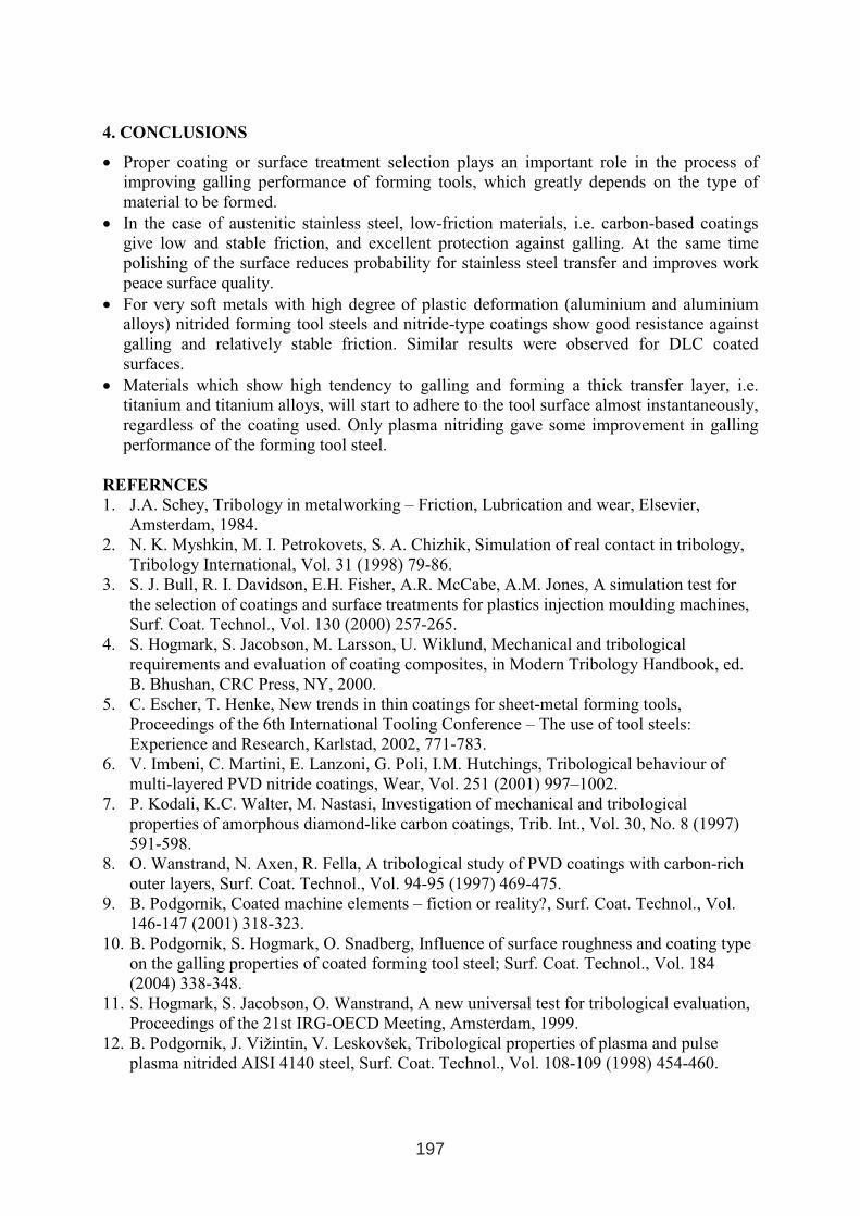
4. CONCLUSIONS
• Proper coating or surface treatment selection plays an important role in the process of
improving galling performance of forming tools, which greatly depends on the type of
material to be formed.
• In the case of austenitic stainless steel, low-friction materials, i.e. carbon-based coatings
give low and stable friction, and excellent protection against galling. At the same time
polishing of the surface reduces probability for stainless steel transfer and improves work
peace surface quality.
• For very soft metals with high degree of plastic deformation (aluminium and aluminium
alloys) nitrided forming tool steels and nitride-type coatings show good resistance against
galling and relatively stable friction. Similar results were observed for DLC coated
surfaces.
• Materials which show high tendency to galling and forming a thick transfer layer, i.e.
titanium and titanium alloys, will start to adhere to the tool surface almost instantaneously,
regardless of the coating used. Only plasma nitriding gave some improvement in galling
performance of the forming tool steel.
REFERNCES
1. J.A. Schey, Tribology in metalworking – Friction, Lubrication and wear, Elsevier,
Amsterdam, 1984.
2. N. K. Myshkin, M. I. Petrokovets, S. A. Chizhik, Simulation of real contact in tribology,
Tribology International, Vol. 31 (1998) 79-86.
3. S. J. Bull, R. I. Davidson, E.H. Fisher, A.R. McCabe, A.M. Jones, A simulation test for
the selection of coatings and surface treatments for plastics injection moulding machines,
Surf. Coat. Technol., Vol. 130 (2000) 257-265.
4. S. Hogmark, S. Jacobson, M. Larsson, U. Wiklund, Mechanical and tribological
requirements and evaluation of coating composites, in Modern Tribology Handbook, ed.
B. Bhushan, CRC Press, NY, 2000.
5. C. Escher, T. Henke, New trends in thin coatings for sheet-metal forming tools,
Proceedings of the 6th International Tooling Conference – The use of tool steels:
Experience and Research, Karlstad, 2002, 771-783.
6. V. Imbeni, C. Martini, E. Lanzoni, G. Poli, I.M. Hutchings, Tribological behaviour of
multi-layered PVD nitride coatings, Wear, Vol. 251 (2001) 997–1002.
7. P. Kodali, K.C. Walter, M. Nastasi, Investigation of mechanical and tribological
properties of amorphous diamond-like carbon coatings, Trib. Int., Vol. 30, No. 8 (1997)
591-598.
8. O. Wanstrand, N. Axen, R. Fella, A tribological study of PVD coatings with carbon-rich
outer layers, Surf. Coat. Technol., Vol. 94-95 (1997) 469-475.
9. B. Podgornik, Coated machine elements – fiction or reality?, Surf. Coat. Technol., Vol.
146-147 (2001) 318-323.
10. B. Podgornik, S. Hogmark, O. Snadberg, Influence of surface roughness and coating type
on the galling properties of coated forming tool steel; Surf. Coat. Technol., Vol. 184
(2004) 338-348.
11. S. Hogmark, S. Jacobson, O. Wanstrand, A new universal test for tribological evaluation,
Proceedings of the 21st IRG-OECD Meeting, Amsterdam, 1999.
12. B. Podgornik, J. Vižintin, V. Leskovšek, Tribological properties of plasma and pulse
plasma nitrided AISI 4140 steel, Surf. Coat. Technol., Vol. 108-109 (1998) 454-460.
197

ADVANCED APPLICATIONS OF PVD AND CVD COATINGS IN
AUTOMOTIVE INDUSTRY: CUTTING TOOLS AND DIES
S. Durante1, D. Franchi
2, M. Rostagno
1
1Centro Ricerche FIAT
2GENTA-PLATIT, Div. Ferioli e Gianotti
ABSTRACT
In the last decades, research for materials innovation in manufacturing fields pushed towards
the development of machining technologies able to sustain the challenges launched by High
speed and Dry Cutting. Nano technologies will have a key-role in the machining of difficult to
cut materials, especially as ultra hard coatings due to their high hardness, toughness and
oxidation resistance. This paper gives an overview about the development of anti-wear PVD
and CVD nano-structured coatings for automotive applications. Different chemical
compositions, coating thickness, cutting parameters and lubrication conditions were tested in
order to build a know how of metals machine-ability and formability with the innovative
nano-structured coatings. Components wear analysis, together with coatings characterization,
provided with data useful to improve further performance in tool life and reliability. The main
target has been to extend the dry or nearly dry manufacturing approach as far as possible.
1. INTRODUCTION
In the last decades the technological process key factor has been undoubtedly the
miniaturization process of electronic devices. So far, we passed through components of some
mm size to microtechnology. Now it is time to deal about with nanodevices and electronical
applications apart, this incoming revolution will strongly impact all the scientific branches
and human daily life. The question is how?
A huge budget allocation has been planned worldwide in the next years, as Fig.1 shows.
United States and Japan are the leaders in this technological competition, but also Europe is
recovering prestige with its Sixth Framework Programme.
As far as concern FIAT Research Center, in the Machining Team are under development
several research projects and activities covering nanostructured materials and coatings for
cutting tools and high efficient machining process. All the cutting tools involved in the
laboratory and industrial test have been built in HSS S290. In the present article an overview
over these activities will be presented.
1 INTERNATIONAL CONFERENCE ON HEAT TREATMENT
AND SURFACE ENGINEERING OF TOOLS AND DIES
st
Pula, Croatia 08 - 11 June, 2005,
IFHTSE 2005
199
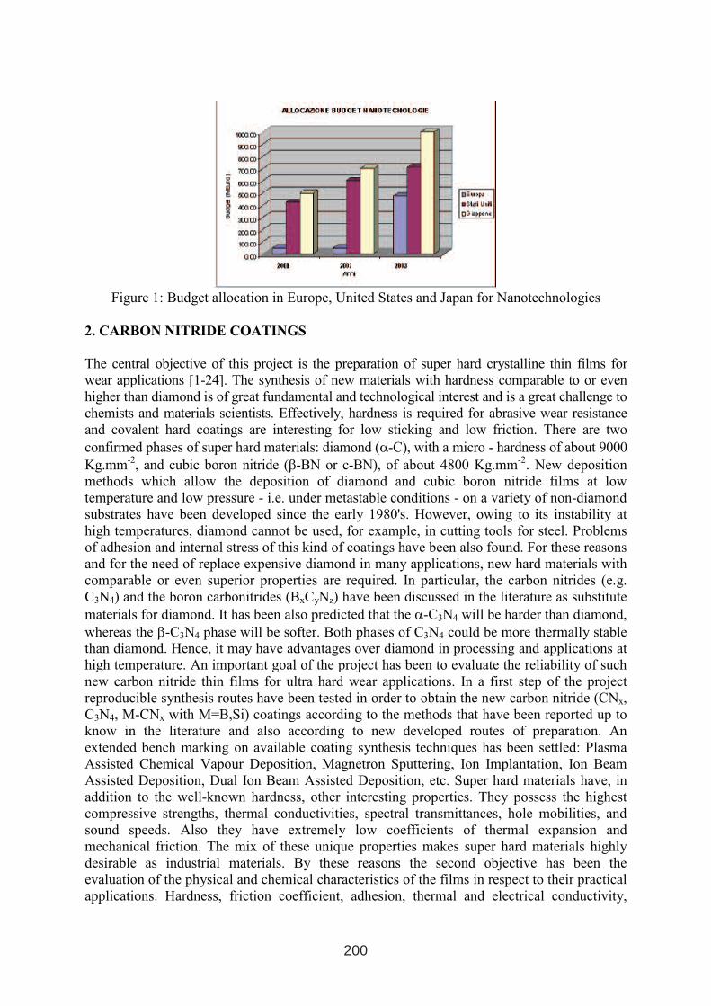
Figure 1: Budget allocation in Europe, United States and Japan for Nanotechnologies
2. CARBON NITRIDE COATINGS
The central objective of this project is the preparation of super hard crystalline thin films for
wear applications [1-24]. The synthesis of new materials with hardness comparable to or even
higher than diamond is of great fundamental and technological interest and is a great challenge to
chemists and materials scientists. Effectively, hardness is required for abrasive wear resistance
and covalent hard coatings are interesting for low sticking and low friction. There are two
confirmed phases of super hard materials: diamond (α-C), with a micro - hardness of about 9000
Kg.mm-2
, and cubic boron nitride (β-BN or c-BN), of about 4800 Kg.mm-2
. New deposition
methods which allow the deposition of diamond and cubic boron nitride films at low
temperature and low pressure - i.e. under metastable conditions - on a variety of non-diamond
substrates have been developed since the early 1980's. However, owing to its instability at
high temperatures, diamond cannot be used, for example, in cutting tools for steel. Problems
of adhesion and internal stress of this kind of coatings have been also found. For these reasons
and for the need of replace expensive diamond in many applications, new hard materials with
comparable or even superior properties are required. In particular, the carbon nitrides (e.g.
C3N4) and the boron carbonitrides (BxCyNz) have been discussed in the literature as substitute
materials for diamond. It has been also predicted that the α-C3N4 will be harder than diamond,
whereas the β-C3N4 phase will be softer. Both phases of C3N4 could be more thermally stable
than diamond. Hence, it may have advantages over diamond in processing and applications at
high temperature. An important goal of the project has been to evaluate the reliability of such
new carbon nitride thin films for ultra hard wear applications. In a first step of the project
reproducible synthesis routes have been tested in order to obtain the new carbon nitride (CNx,
C3N4, M-CNx with M=B,Si) coatings according to the methods that have been reported up to
know in the literature and also according to new developed routes of preparation. An
extended bench marking on available coating synthesis techniques has been settled: Plasma
Assisted Chemical Vapour Deposition, Magnetron Sputtering, Ion Implantation, Ion Beam
Assisted Deposition, Dual Ion Beam Assisted Deposition, etc. Super hard materials have, in
addition to the well-known hardness, other interesting properties. They possess the highest
compressive strengths, thermal conductivities, spectral transmittances, hole mobilities, and
sound speeds. Also they have extremely low coefficients of thermal expansion and
mechanical friction. The mix of these unique properties makes super hard materials highly
desirable as industrial materials. By these reasons the second objective has been the
evaluation of the physical and chemical characteristics of the films in respect to their practical
applications. Hardness, friction coefficient, adhesion, thermal and electrical conductivity,
200
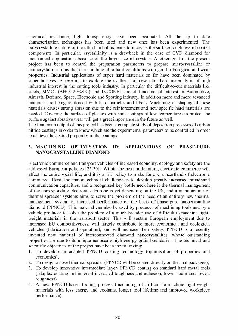
chemical resistance, light transparency have been evaluated. All the up to date
characterisation techniques has been used and new ones has been experimented. The
polycrystalline nature of the ultra hard films tends to increase the surface roughness of coated
components. In particular, crystallinity is a drawback in the case of CVD diamond for
mechanical applications because of the large size of crystals. Another goal of the present
project has been to control the preparation parameters to prepare microcrystalline or
nanocrystalline films that can combine ultra hard conditions with good tribological and wear
properties. Industrial applications of super hard materials so far have been dominated by
superabrasives. A research to explore the synthesis of new ultra hard materials is of high
industrial interest in the cutting tools industry. In particular the difficult-to-cut materials like
steels, MMCs (Al+10-20%SiC) and INCONEL are of fundamental interest in Automotive,
Aircraft, Defence, Space, Electronic and Sporting industry. In addition more and more advanced
materials are being reinforced with hard particles and fibers. Machining or shaping of these
materials causes strong abrasion due to the reinforcement and new specific hard materials are
needed. Covering the surface of plastics with hard coatings at low temperatures to protect the
surface against abrasive wear will get a great importance in the future as well.
The final main output of this project has been a complete study of deposition processes of carbon
nitride coatings in order to know which are the experimental parameters to be controlled in order
to achieve the desired properties of the coatings.
3. MACHINING OPTIMISATION BY APPLICATIONS OF PHASE-PURE
NANOCRYSTALLINE DIAMOND
Electronic commerce and transport vehicles of increased economy, ecology and safety are the
addressed European policies [25-30].. Within the next millennium, electronic commerce will
affect the entire social life, and it is a EU policy to make Europe a heartland of electronic
commerce. Here, the major technical challenge is to develop greatly increased broadband
communication capacities, and a recognised key bottle neck here is the thermal management
of the corresponding electronics. Europe is yet depending on the US, and a manufacturer of
thermal spreader systems aims to solve the problem of the need of an entirely new thermal
management system of increased performance on the basis of phase-pure nanocrystalline
diamond (PPNCD). This material can also be used by producer of machining tools and by a
vehicle producer to solve the problem of a much broader use of difficult-to-machine light-
weight materials in the transport sector. This will sustain European employment due to
increased EU competitiveness, will largely contribute to more economical and ecological
vehicles (fabrication and operation), and will increase their safety. PPNCD is a recently
invented new material of interconnected diamond nanocrystallites, whose outstanding
properties are due to its unique nanoscale high-energy grain boundaries. The technical and
scientific objectives of the project have been the following:
1. To develop an adapted PPNCD coating technology (optimisation of properties and
economics),
2. To design a novel thermal spreader (PPNCD will be coated directly on thermal packages);
3. To develop innovative intermediate layer/ PPNCD coating on standard hard metal tools
(”duplex coating” of inherent increased toughness and adhesion, lower strain and lowest
roughness)
4. A new PPNCD-based tooling process (machining of difficult-to-machine light-weight
materials with less energy and coolants, longer tool lifetime and improved workpiece
performance).
201
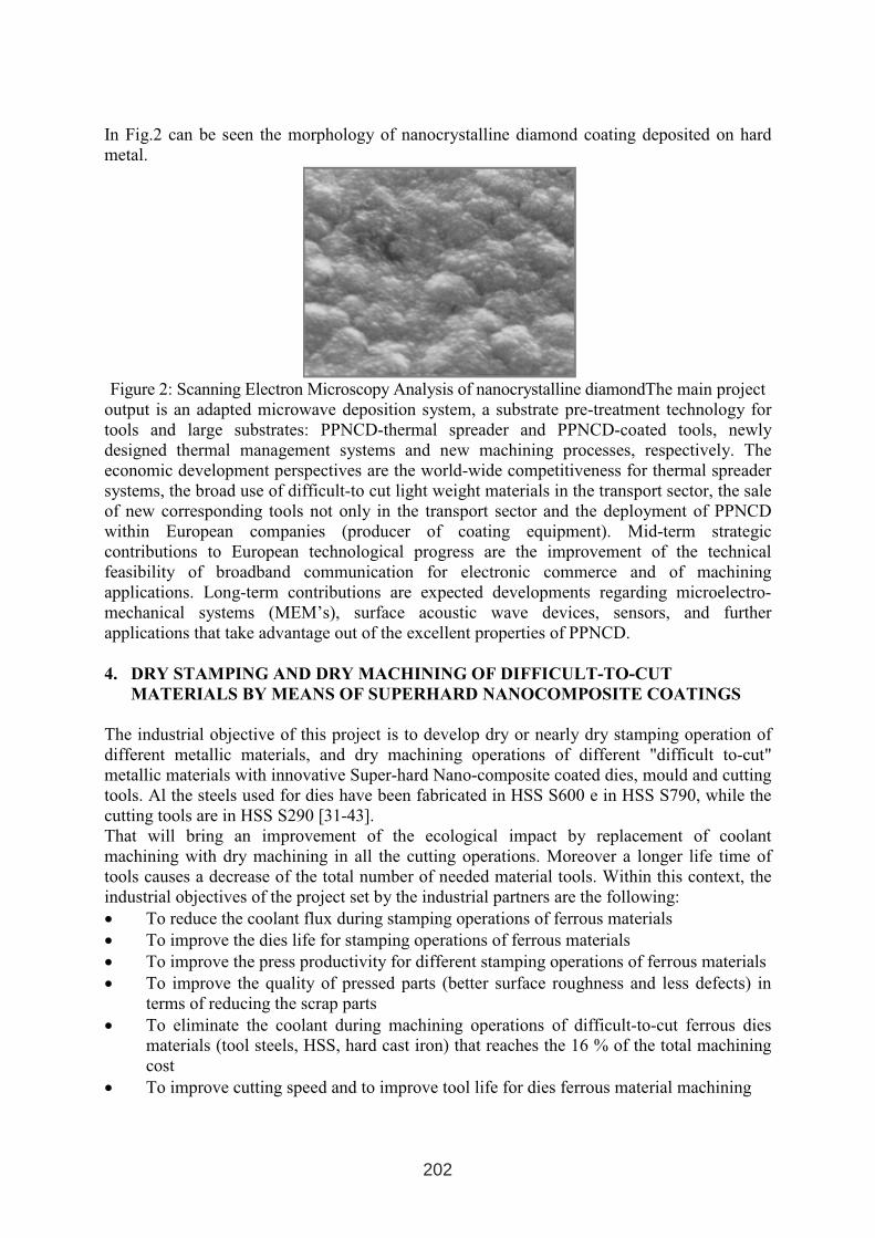
In Fig.2 can be seen the morphology of nanocrystalline diamond coating deposited on hard
metal.
Figure 2: Scanning Electron Microscopy Analysis of nanocrystalline diamondThe main project
output is an adapted microwave deposition system, a substrate pre-treatment technology for
tools and large substrates: PPNCD-thermal spreader and PPNCD-coated tools, newly
designed thermal management systems and new machining processes, respectively. The
economic development perspectives are the world-wide competitiveness for thermal spreader
systems, the broad use of difficult-to cut light weight materials in the transport sector, the sale
of new corresponding tools not only in the transport sector and the deployment of PPNCD
within European companies (producer of coating equipment). Mid-term strategic
contributions to European technological progress are the improvement of the technical
feasibility of broadband communication for electronic commerce and of machining
applications. Long-term contributions are expected developments regarding microelectro-
mechanical systems (MEM’s), surface acoustic wave devices, sensors, and further
applications that take advantage out of the excellent properties of PPNCD.
4. DRY STAMPING AND DRY MACHINING OF DIFFICULT-TO-CUT
MATERIALS BY MEANS OF SUPERHARD NANOCOMPOSITE COATINGS
The industrial objective of this project is to develop dry or nearly dry stamping operation of
different metallic materials, and dry machining operations of different "difficult to-cut"
metallic materials with innovative Super-hard Nano-composite coated dies, mould and cutting
tools. Al the steels used for dies have been fabricated in HSS S600 e in HSS S790, while the
cutting tools are in HSS S290 [31-43].
That will bring an improvement of the ecological impact by replacement of coolant
machining with dry machining in all the cutting operations. Moreover a longer life time of
tools causes a decrease of the total number of needed material tools. Within this context, the
industrial objectives of the project set by the industrial partners are the following:
• To reduce the coolant flux during stamping operations of ferrous materials
• To improve the dies life for stamping operations of ferrous materials
• To improve the press productivity for different stamping operations of ferrous materials
• To improve the quality of pressed parts (better surface roughness and less defects) in
terms of reducing the scrap parts
• To eliminate the coolant during machining operations of difficult-to-cut ferrous dies
materials (tool steels, HSS, hard cast iron) that reaches the 16 % of the total machining
cost
• To improve cutting speed and to improve tool life for dies ferrous material machining
202
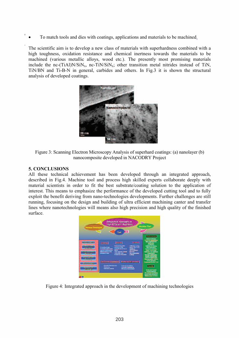
• To match tools and dies with coatings, applications and materials to be machined.
The scientific aim is to develop a new class of materials with superhardness combined with a
high toughness, oxidation resistance and chemical inertness towards the materials to be
machined (various metallic alloys, wood etc.). The presently most promising materials
include the nc-(TiAl)N/SiNx, nc-TiN/SiNx; other transition metal nitrides instead of TiN,
TiN/BN and Ti-B-N in general, carbides and others. In Fig.3 it is shown the structural
analysis of developed coatings.
Figure 3: Scanning Electron Microscopy Analysis of superhard coatings: (a) nanolayer (b)
nanocomposite developed in NACODRY Project
5. CONCLUSIONS
All these technical achievement has been developed through an integrated approach,
described in Fig.4. Machine tool and process high skilled experts collaborate deeply with
material scientists in order to fit the best substrate/coating solution to the application of
interest. This means to emphasize the performance of the developed cutting tool and to fully
exploit the benefit deriving from nano-technologies developments. Further challenges are still
running, focusing on the design and building of ultra efficient machining canter and transfer
lines where nanotechnologies will means also high precision and high quality of the finished
surface.
Figure 4: Integrated approach in the development of machining technologies
203
REFERENCES
1. J.C.Angus, C.C.Hayman, Science 241, 913 (1988)
2. K.E.Spear, J. Am. Ceram. Soc. 72, 171 (1989)
3. W.A.Yarbrough, R.Messier, Science 247, 688 (1990)
4. P.K.Bachmann, Keram. Z. 2, 93 (1992)
5. A.Y.Liu, M.L.Cohen, Science 245, 841 (1989)
6. Ch.-M.Sung, M.Sung, Materials Chemistry and Physics 43, 1 (1996)
7. J.Hoggin, Chem. Eng. News, May 25, 20 (1992)
8. C.Niu, Y.Z.Lu, C.M.Lieber, Science 261, 334 (1993)
9. K.J.Boyd, and oth. J. Vac. Sci. Technol. A13, 2110 (1995)
10. K.M.Yu, M.L.Cohen, B.E.Haller, W.L.Hansen, and oth., Phys. Rev. B 49,5034 (1994)
11. 11. A.Hoffman, H.Geller, and oth., Surf. Coat. Tech. 68/69, 616 (1994)
12. L.Maya, D.R.Cole, E.W.Hagaman, J. Am. Ceram. Soc. 74, 1686 (1991).
13. M.R.Wixon, J. Am. Ceram. Soc. 73, 1973 (1990)
14. L.Holland, J. Vac. Sci. Technol. 14, 5 (1977)
15. L.Holland, Thin Solid Films 58, 107 (1979)
16. F.Saugnac, F.Teyssandier, A.Marchand, J. Am. Ceram. Soc. 75, 161 (1992)
17. A.Badzian, Appl. Phys. Lett. 53, 2495 (1988)
18. K.Ploog, P.Rauh, W.Stoeger, H.Schmidt, J. Cryst. Growth 13/14, 350 (1972)
19. K.Ploog, H.Schmidt, E.Amberger, G.Will, K.H.Kossobutzki, J.Less-Com.Met., 161 (1972)
20. R.Riedel, Adv. Mat. 6, 549 (1994)
21. Ch.-M.Sung, M.Sung, Materials Chemistry and Physics 43, 1 (1996).
22. K.K.Schuegraf (ed.), “Handbook of Thin-Film Dep. Proc.”, Noyes Publication, (1988).
23. I.Maissel, R.Glang, “Handbook of Thin Film Technology”, McGraw-Hill, NY (1970).
24. W.Ensinger, Rev. Sci. Instrum. 63, 5217 (1992).
25. D.M. Gruen, S.Liu, A.R. Krauss, J. Luo and X.Pan, Appl. Phys.Lett. 64 (1994) 1504
26. D.M. Gruen, C.D. Zuiker, A.R. Krauss, and X.Pan, J.Vac.Sci.Technol. 13 (1995)1628
27. A.Erdemir, M.Halter, G.R.Fenske, R.Csencsits, and oth. Tribology Trans. 40 (1997)
667.
28. A.Erdemir, C.Bindal, G.R.Fenske, and oth., Diamond Films Technol. 6(1) (1996)
29. D.M. Gruen, A.R. Krauss, and oth., Electrochem. Soc. Proc. 97-25 (1997)
30. D. Zhou, A.R.Krauss, and oth., J.Electrochem. Soc. 144(8) (1997) L224.
31. S. Veprek, S. Reiprich and Li Shizhi, Appl. Phys. Lett. 66(1995)2540.
32. S. Veprek and S. Reiprich, Thin Solid Films 268(1996)64.
33. S. Veprek, M. Haussmann and S. Reiprich, J. Vac. Sci. Technol. A 14(1996)46.
34. S. Veprek, M. Haussmann and Li Shizhi, Electrochem. Soc. Proc. 96-5(1996)619.
35. S. Christiansen, M. Albrecht, H.P. Strunk, S. Veprek, J. Vac. Sci. Technol.,
B16(1998)19.
36. S. Veprek, J. Vac. Sci. Technol. A xx(1999) September, in press.
37. A. Niederhofer, P. Nesladek, H.-D. Männling, S. Veprek and M. Jilek, Int. Conf. on
Metallurgical Coatings and Thin Films, San Diego, April 1999.
38. P. Holubar and oth., Int. Conf. on Metal. Coatings and Thin Films, San Diego, April
1999.
39. R. Grün, Surface and Coatings Technology, Vol. 60 (1993) p. 613.
40. R. Stolz (ed.), Vol 14, Gühring KG (1994) p. 21.
41. M.A. Kennicott, Lubricants World, Vol 5, No. 2 (1995).
42. 43. D. Jones, Vol 1.1, Issue 9 (1995).
43. 44. T. Cselle, A. Barimani, Surface and Coatings Technology, Vol 76/77 (1995) p 712.
204
HARDIDE™ – ADVANCED CVD COATING FOR TOOLS AND DIES
Dr.Yuri N. Zhuk, Technical Director, Hardide Plc (UK).
Unit 11, Wedgwood Road, Bicester, Oxfordshire OX26 4UL, United Kingdom
ABSTRACT
Hardide™ is a new low-temperature CVD Tungsten Carbide coating with ultra-high hardness (varied from 1100 Hv up to 3500 HV), low dry friction coefficient (typically 0.2), resistant to corrosion, acids, aggressive media. Hardide can be produced on steel, including stainless steel and some tool steels, with coating thickness varied from 5 to 100 microns. Homogeneous pore-free structure of Hardide facilitates finishing by honing, polishing, mirror finish can be achieved with suitable substrate. Gas-phase CVD process allows coating internal surfaces and items of complex shape like dies, moulds. Use of Hardide with cutting tools for paper and plastics makes them self-sharpening. Application of Hardide increases life of tools and dies and reduces down-time.
Key words: CVD, Tungsten Carbide, hard coating, wear-resistance, corrosion-resistance, low friction, non-stick coating.
1. INTRODUCTION
A number of hard coatings and surface treatments are successfully used to increase life of tools and dies, thin PVD and CVD coatings on cemented carbide metal cutting tools, hard Chrome plating of moulds, spray coatings and Nitriding are most widely used techniques. Meanwhile each of these well-established surface engineering processes has its limitations, in particular the currently used PVD and CVD processes produce very thin coatings typicallyless than 5 microns [1, 2, 3], which can not resist abrasive or erosive conditions. Chrome plating is under pressure for environmental reasons, HVOF spray coating is considered as a prospective alternative to Chrome but it is not suitable for internal surfaces. Most of these treatments do not protect tools against corrosion or aggressive media.
Hardide is a new coating material which offers a unique combination of properties making it a promising material for applications with tools and dies [4, 7, 8]. Hardide was introduced into full-scale commercial use in 2003 when Hardide Ltd established the first production centre in Oxfordshire, UK, resulting from many years of research and development.
The coating consists of dense and homogeneous binder-free Tungsten Carbide produced by low temperature CVD process. Hardide has ultra-high hardness which can be varied from 1100 HV up to 3500 HV, low friction coefficient (0.2 – 0.3), is resistant to corrosion and aggressive media. Hardide is crystallised from gas phase atom-by-atom that allows to coat internal and shaped “out of line-of-sight” surfaces, such as a die cavity or a mould of a complex shape.
1 INTERNATIONAL CONFERENCE ON HEAT TREATMENT
AND SURFACE ENGINEERING OF TOOLS AND DIES
st
Pula, Croatia 08 - 11 June, 2005,
IFHTSE 2005
205
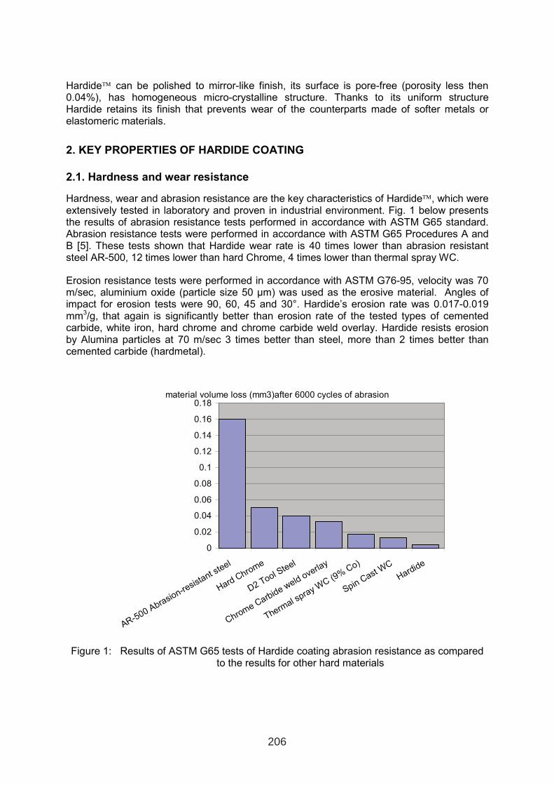
Hardide can be polished to mirror-like finish, its surface is pore-free (porosity less then 0.04%), has homogeneous micro-crystalline structure. Thanks to its uniform structure Hardide retains its finish that prevents wear of the counterparts made of softer metals or elastomeric materials.
2. KEY PROPERTIES OF HARDIDE COATING
2.1. Hardness and wear resistance
Hardness, wear and abrasion resistance are the key characteristics of Hardide, which were extensively tested in laboratory and proven in industrial environment. Fig. 1 below presents the results of abrasion resistance tests performed in accordance with ASTM G65 standard. Abrasion resistance tests were performed in accordance with ASTM G65 Procedures A and B [5]. These tests shown that Hardide wear rate is 40 times lower than abrasion resistant steel AR-500, 12 times lower than hard Chrome, 4 times lower than thermal spray WC.
Erosion resistance tests were performed in accordance with ASTM G76-95, velocity was 70 m/sec, aluminium oxide (particle size 50 µm) was used as the erosive material. Angles of impact for erosion tests were 90, 60, 45 and 30°. Hardide’s erosion rate was 0.017-0.019 mm3/g, that again is significantly better than erosion rate of the tested types of cemented carbide, white iron, hard chrome and chrome carbide weld overlay. Hardide resists erosion by Alumina particles at 70 m/sec 3 times better than steel, more than 2 times better than cemented carbide (hardmetal).
material volume loss (mm3)after 6000 cycles of abrasion
0
0.02
0.04
0.06
0.08
0.1
0.12
0.14
0.16
0.18
AR-500 Abrasion-resistant steel
HardChrome
D2 Tool Steel
Chrome Carbide weldoverla
y
Thermal spray W
C(9%
Co)
SpinCast W
C
Hardide
Figure 1: Results of ASTM G65 tests of Hardide coating abrasion resistance as compared to the results for other hard materials
206
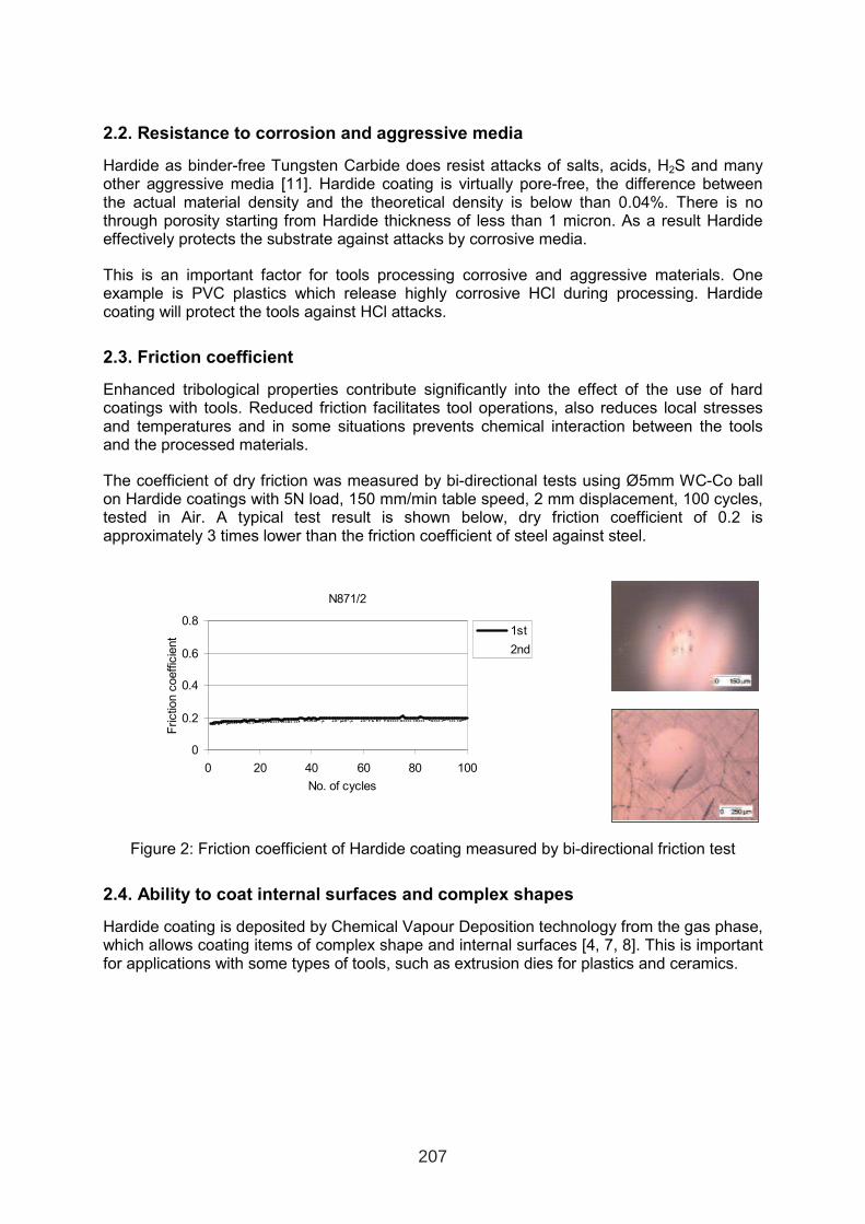
2.2. Resistance to corrosion and aggressive media
Hardide as binder-free Tungsten Carbide does resist attacks of salts, acids, H2S and many other aggressive media [11]. Hardide coating is virtually pore-free, the difference between the actual material density and the theoretical density is below than 0.04%. There is no through porosity starting from Hardide thickness of less than 1 micron. As a result Hardide effectively protects the substrate against attacks by corrosive media.
This is an important factor for tools processing corrosive and aggressive materials. One example is PVC plastics which release highly corrosive HCl during processing. Hardide coating will protect the tools against HCl attacks.
2.3. Friction coefficient
Enhanced tribological properties contribute significantly into the effect of the use of hard coatings with tools. Reduced friction facilitates tool operations, also reduces local stresses and temperatures and in some situations prevents chemical interaction between the tools and the processed materials.
The coefficient of dry friction was measured by bi-directional tests using Ø5mm WC-Co ball on Hardide coatings with 5N load, 150 mm/min table speed, 2 mm displacement, 100 cycles, tested in Air. A typical test result is shown below, dry friction coefficient of 0.2 is approximately 3 times lower than the friction coefficient of steel against steel.
N871/2
0
0.2
0.4
0.6
0.8
0 20 40 60 80 100
No. of cycles
Friction
coeffic
ient
1st
2nd
Figure 2: Friction coefficient of Hardide coating measured by bi-directional friction test
2.4. Ability to coat internal surfaces and complex shapes
Hardide coating is deposited by Chemical Vapour Deposition technology from the gas phase, which allows coating items of complex shape and internal surfaces [4, 7, 8]. This is important for applications with some types of tools, such as extrusion dies for plastics and ceramics.
207
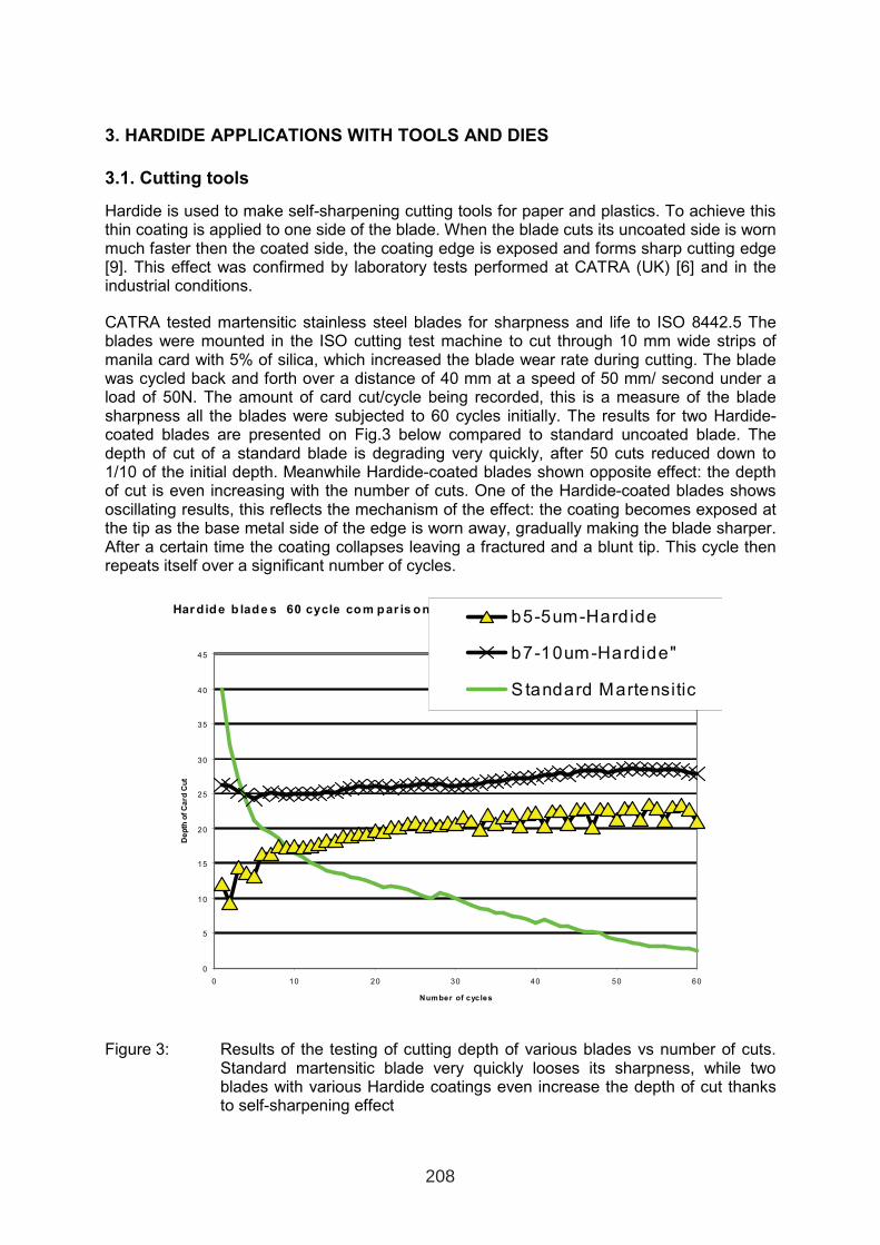
3. HARDIDE APPLICATIONS WITH TOOLS AND DIES
3.1. Cutting tools
Hardide is used to make self-sharpening cutting tools for paper and plastics. To achieve this thin coating is applied to one side of the blade. When the blade cuts its uncoated side is worn much faster then the coated side, the coating edge is exposed and forms sharp cutting edge [9]. This effect was confirmed by laboratory tests performed at CATRA (UK) [6] and in the industrial conditions.
CATRA tested martensitic stainless steel blades for sharpness and life to ISO 8442.5 The blades were mounted in the ISO cutting test machine to cut through 10 mm wide strips of manila card with 5% of silica, which increased the blade wear rate during cutting. The blade was cycled back and forth over a distance of 40 mm at a speed of 50 mm/ second under a load of 50N. The amount of card cut/cycle being recorded, this is a measure of the blade sharpness all the blades were subjected to 60 cycles initially. The results for two Hardide-coated blades are presented on Fig.3 below compared to standard uncoated blade. The depth of cut of a standard blade is degrading very quickly, after 50 cuts reduced down to 1/10 of the initial depth. Meanwhile Hardide-coated blades shown opposite effect: the depth of cut is even increasing with the number of cuts. One of the Hardide-coated blades showsoscillating results, this reflects the mechanism of the effect: the coating becomes exposed at the tip as the base metal side of the edge is worn away, gradually making the blade sharper. After a certain time the coating collapses leaving a fractured and a blunt tip. This cycle then repeats itself over a significant number of cycles.
Har dide b lade s 60 cycle com par is on
0
5
10
15
20
25
30
35
40
45
0 10 20 30 40 50 60
Number of cycles
De
pth
of
Ca
rdC
ut
b5-5um-Hardide
b7-10um-Hardide"
S tandard Martensitic
Figure 3: Results of the testing of cutting depth of various blades vs number of cuts. Standard martensitic blade very quickly looses its sharpness, while two blades with various Hardide coatings even increase the depth of cut thanks to self-sharpening effect
208
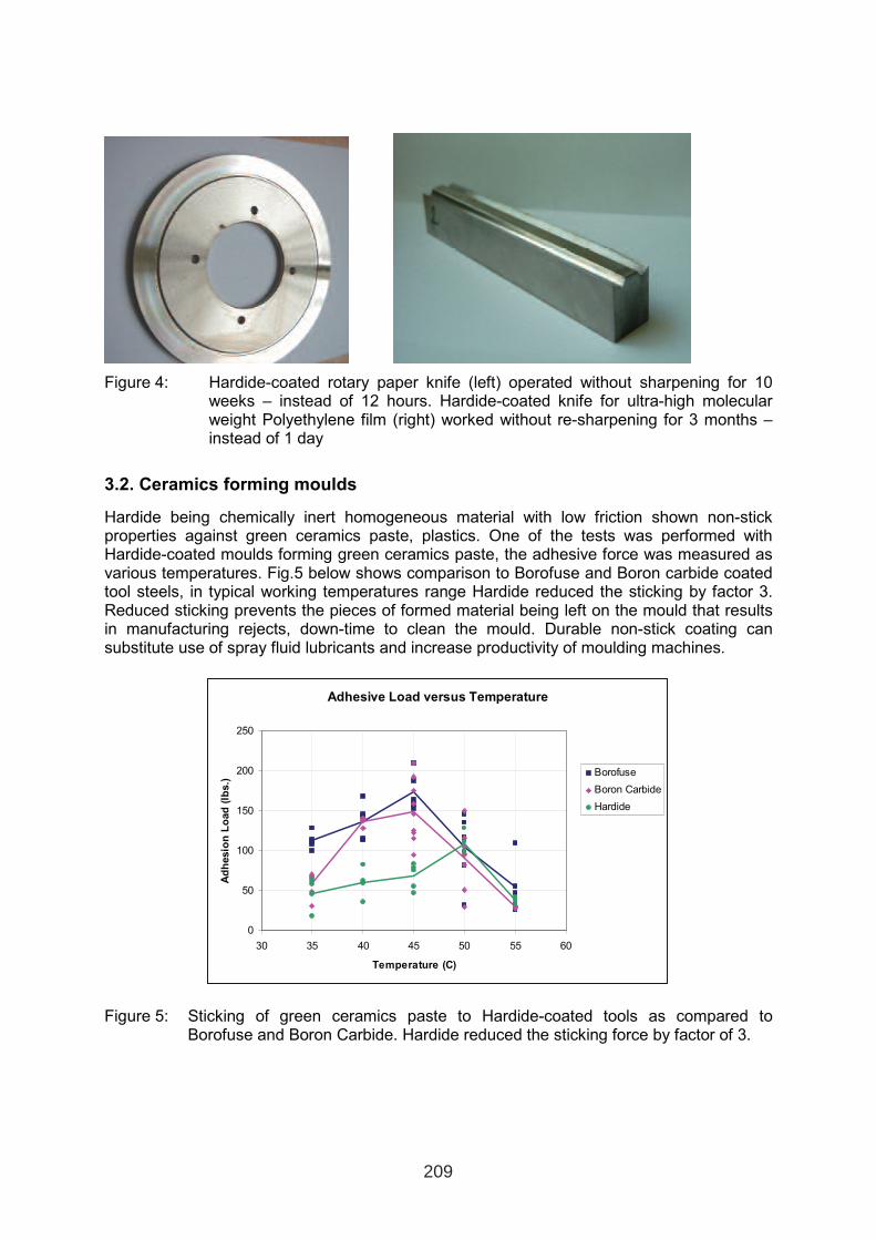
Figure 4: Hardide-coated rotary paper knife (left) operated without sharpening for 10 weeks – instead of 12 hours. Hardide-coated knife for ultra-high molecular weight Polyethylene film (right) worked without re-sharpening for 3 months – instead of 1 day
3.2. Ceramics forming moulds
Hardide being chemically inert homogeneous material with low friction shown non-stickproperties against green ceramics paste, plastics. One of the tests was performed with Hardide-coated moulds forming green ceramics paste, the adhesive force was measured as various temperatures. Fig.5 below shows comparison to Borofuse and Boron carbide coated tool steels, in typical working temperatures range Hardide reduced the sticking by factor 3. Reduced sticking prevents the pieces of formed material being left on the mould that results in manufacturing rejects, down-time to clean the mould. Durable non-stick coating can substitute use of spray fluid lubricants and increase productivity of moulding machines.
Figure 5: Sticking of green ceramics paste to Hardide-coated tools as compared to Borofuse and Boron Carbide. Hardide reduced the sticking force by factor of 3.
Adhesive Load versus Temperature
0
50
100
150
200
250
30 35 40 45 50 55 60
Temperature (C)
Ad
hesio
nL
oad
(lb
s.)
Borofuse
Boron Carbide
Hardide
209
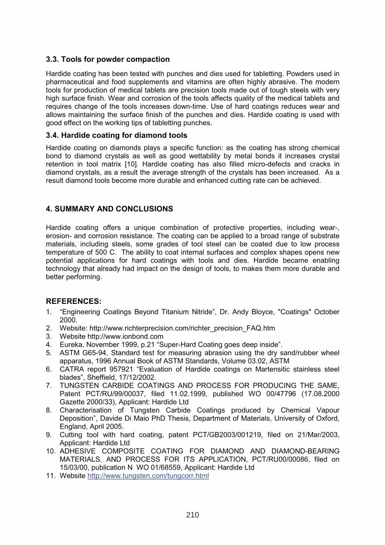
3.3. Tools for powder compaction
Hardide coating has been tested with punches and dies used for tabletting. Powders used in pharmaceutical and food supplements and vitamins are often highly abrasive. The modern tools for production of medical tablets are precision tools made out of tough steels with veryhigh surface finish. Wear and corrosion of the tools affects quality of the medical tablets and requires change of the tools increases down-time. Use of hard coatings reduces wear and allows maintaining the surface finish of the punches and dies. Hardide coating is used with good effect on the working tips of tabletting punches.
3.4. Hardide coating for diamond tools
Hardide coating on diamonds plays a specific function: as the coating has strong chemical bond to diamond crystals as well as good wettability by metal bonds it increases crystal retention in tool matrix [10]. Hardide coating has also filled micro-defects and cracks in diamond crystals, as a result the average strength of the crystals has been increased. As a result diamond tools become more durable and enhanced cutting rate can be achieved.
4. SUMMARY AND CONCLUSIONS
Hardide coating offers a unique combination of protective properties, including wear-, erosion- and corrosion resistance. The coating can be applied to a broad range of substrate materials, including steels, some grades of tool steel can be coated due to low process temperature of 500 C. The ability to coat internal surfaces and complex shapes opens new potential applications for hard coatings with tools and dies. Hardide became enabling technology that already had impact on the design of tools, to makes them more durable and better performing.
REFERENCES:
1. “Engineering Coatings Beyond Titanium Nitride”, Dr. Andy Bloyce, "Coatings" October 2000.
2. Website: http://www.richterprecision.com/richter_precision_FAQ.htm 3. Website http://www.ionbond.com 4. Eureka, November 1999, p.21 “Super-Hard Coating goes deep inside”. 5. ASTM G65-94, Standard test for measuring abrasion using the dry sand/rubber wheel
apparatus, 1996 Annual Book of ASTM Standards, Volume 03.02, ASTM 6. CATRA report 957921 “Evaluation of Hardide coatings on Martensitic stainless steel
blades”, Sheffield, 17/12/2002. 7. TUNGSTEN CARBIDE COATINGS AND PROCESS FOR PRODUCING THE SAME,
Patent PCT/RU/99/00037, filed 11.02.1999, published WO 00/47796 (17.08.2000 Gazette 2000/33), Applicant: Hardide Ltd
8. Characterisation of Tungsten Carbide Coatings produced by Chemical Vapour Deposition”, Davide Di Maio PhD Thesis, Department of Materials, University of Oxford, England, April 2005.
9. Cutting tool with hard coating, patent PCT/GB2003/001219, filed on 21/Mar/2003, Applicant: Hardide Ltd
10. ADHESIVE COMPOSITE COATING FOR DIAMOND AND DIAMOND-BEARING MATERIALS, AND PROCESS FOR ITS APPLICATION, PCT/RU00/00086, filed on 15/03/00, publication N WO 01/68559, Applicant: Hardide Ltd
11. Website http://www.tungsten.com/tungcorr.html
210
COMPARISON OF MECHANICAL PROPERTIES OF VARIOUS PVD
HARD COATINGS FOR FORMING TOOLS
Đ. Goršćak1, P. Panjan
2, M. Čekada
2, L. Ćurković
3
1Končar-Alati d.d, Fallerovo šetalište 22, 10000 Zagreb, Croatia
2Jožef Stefan Institute, Jamova 39, 1000 Ljubljana, Slovenia
3University of Zagreb, Faculty of Mechanical Engineering and Naval Architecture, Ivana
Lučića 5, 10000 Zagreb, Croatia
ABSTRACT
In this paper we compare the basic mechanical properties of PVD hard coatings which are
currently used in company Končar Alati for wear protection of forming tools manufactured on
request of the Electrolux Group, with emphasis on the company Electrolux Home Products
Denmark A/S. This company has high demands on tool performance for machining and
forming of several different workpiece materials, such as steel sheet, stainless steel,
aluminium and Teflon-coated sheet. Two different deposition methods were used for
preparation of hard coatings: sputtering using unballanced magnetron sources – CC800
(CemeCon) and cathode arc evaporation (BAI 1200 (Balzers)). The investigated coatings
were deposited on four different tool steels. We found that the hard coatings investigated in
this work showed wide range of mechanical properties; microhardness in the range of 900-
3200 HV, critical load for total delamination in the range of 75-135 N, indentation modulus in
the range of 120-390 GPa, while the scratching coefficient was in the range 0.02-0.09.
Key words: PVD hard coating, metal sheet forming tool, tool steel
1. INTRODUCTION
The demands on forming tool performance are constantly increasing. Besides the steel quality
itself, surface coatings will have an important role in tool wear resistance [1-10]. Nowadays
coated forming tools are necessary esspecially for forming processes of new high-strength
steel sheets developed in recent years (dualphase steel, TRIP-steel, martensite steel), while
forming processes of such materials is very difficult due to high press and blankholder forces
[5]. The hard coating appropriate for protection of forming tools must have not only a high
wear resistance, but also a low coefficient of friction and low tendency to workpiece material
pick-up. Their high hardness restricts abrasive wear, while a low coefficient of friction
provides additional lubrication. Therefore the use of lubricants can be reduced to a minimum.
This has a positive impact on the environment and on the whole economy of the forming
process. Hard coatings should also reduce adhesive wear due to material transfer between the
contact surfaces (galling) [3]. In forming applications this demand is often equally important
as the wear resistance. Nowadays a large part of heavy forming and stamping tools e.g. in car
1 INTERNATIONAL CONFERENCE ON HEAT TREATMENT
AND SURFACE ENGINEERING OF TOOLS AND DIES
st
Pula, Croatia 08 - 11 June, 2005,
IFHTSE 2005
211
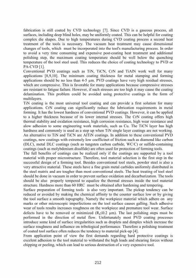
fabrication is still coated by CVD technology [7]. Since CVD is a gaseous process, all
surfaces, including deep blind holes, may be uniformly coated. This can be helpful for coating
complex die shapes. Due to high temperatures during CVD coating process a second heat
treatment of the tools is necessary. The vacuum heat treatment may cause dimensional
changes of tools, which must be incorporated into the tool's manufacturing process. In order
to avoid a very time consuming and expensive post-coating heat treatment and additional
polishing step, the maximum coating temperature should be well below the quenching
temperature of the tool steel used. This reduces the choice of coating technology to PVD or
PA-CVD [1].
Conventional PVD coatings such as TiN, TiCN, CrN and TiAlN work well for many
applications [8,9,10]. The minimum coating thickness for metal stamping and forming
applications should be no less than 4-5 µm. PVD coatings have very high residual stresses,
which are compressive. This is favorable for many applications because compressive stresses
are resistant to fatigue failure. However, if such stresses are too high it may cause the coating
delamination. This problem could be avoided using protective coatings in the form of
multilayers.
TiN coating is the most universal tool coating and can provide a first solution for many
applications. CrN coating can significantly reduce the lubrication requirements in metal
forming. It has the lowest hardness of conventional PVD coatings. However, it can be applied
to a higher thickness because of its lower internal stresses. The CrN coating offers high
thermal stability and oxidation resistance, high corrosion resistance, high wear resistance and
alow adhesion to some engineering work materials, such as Cu. The TiCN layer has high
hardness and commonly is used as a step up when TiN single layer coatings are not working.
An alternative to TiN and TiCN are AlTiN coatings. In addition to these conventional PVD
coatings, new coatings with extremely low coefficinet of friction such as diamond like carbon
(DLC), metal DLC coatings (such as tungsten carbon carbide, WC/C) or sulfide-containing
coatings (such as molybdenium disulfide) are often used for protection of forming tools.
The full benefits of coatings can be realized only if the coatings are supported by a tool
material with proper microstructure. Therefore, tool material selection is the first step in the
successful design of a forming tool. Besides conventional tool steels, powder steel is also a
very attractive material. These steels have a fine grain metal carbides uniformly distributed in
the steel matrix and are tougher than most conventional steels. The heat treating of tool steel
should be done in vacuum in order to prevent surface oxidation and decarburization. The tools
should be also properly tempered to equalize the thermal stresses inside the tool material
structure. Hardness more than 60 HRC must be obtained after hardening and tempering.
Surface preparation of forming tools is also very important. The pickup tendency can be
reduced or avoided by making the chemical affinity to the counter surface low or by giving
the tool surface a smooth topography. Namely the workpiece material which adhere on any
marks or other microscopic imperfections on the tool surface causes galling. Such adhesive
wear of tools results increases roughness on the workpiece and premature tool wear. Surface
defects have to be removed or minimized (Ra≤0.2 µm). The last polishing steps must be
performed in the direction of metal flow. Unfortunately most PVD coating processes
introduce some kind of surface irregularities such as droplets and dimples which increase the
surface roughness and influence on tribological performance. Therefore a polishing treatment
of coated tool surface often reduces the tendency to material pick-up [4].
From application point of view the first demands regarding hard protective coatings is
excelent adhesion to the tool material to withstand the high loads and shearing forces without
chipping or peeling, which can lead to serious destruction of a very expensive tool.
212
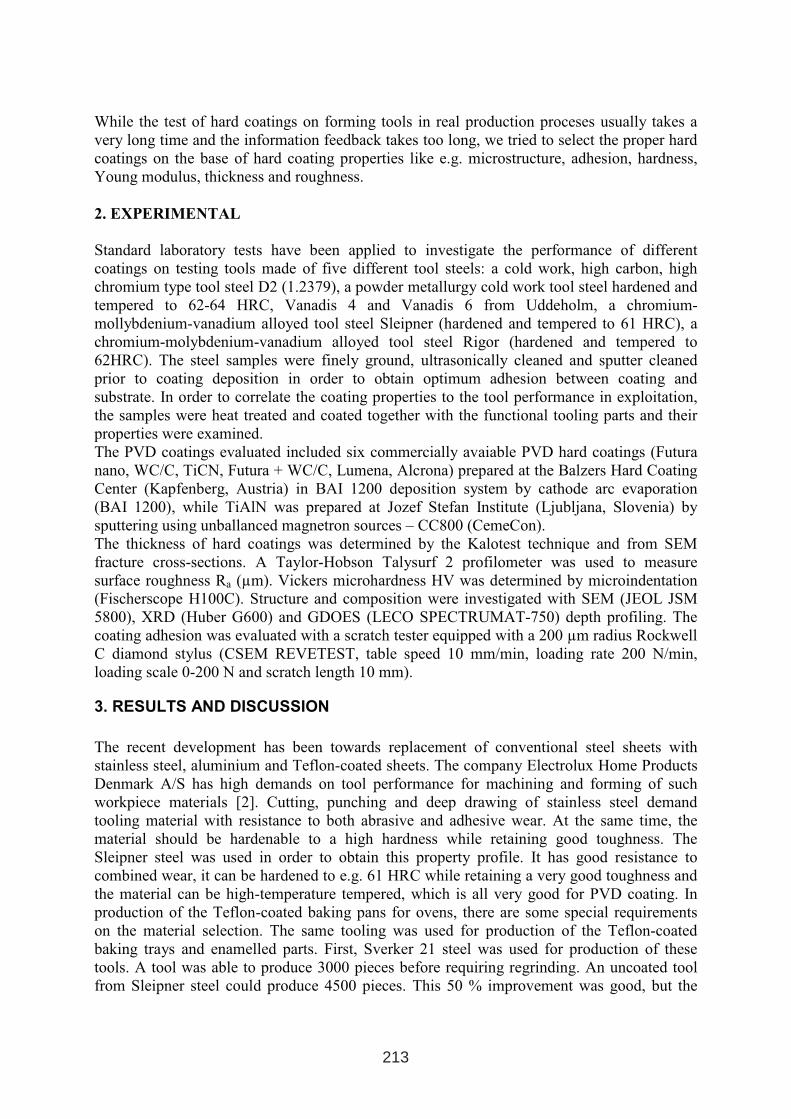
While the test of hard coatings on forming tools in real production proceses usually takes a
very long time and the information feedback takes too long, we tried to select the proper hard
coatings on the base of hard coating properties like e.g. microstructure, adhesion, hardness,
Young modulus, thickness and roughness.
2. EXPERIMENTAL
Standard laboratory tests have been applied to investigate the performance of different
coatings on testing tools made of five different tool steels: a cold work, high carbon, high
chromium type tool steel D2 (1.2379), a powder metallurgy cold work tool steel hardened and
tempered to 62-64 HRC, Vanadis 4 and Vanadis 6 from Uddeholm, a chromium-
mollybdenium-vanadium alloyed tool steel Sleipner (hardened and tempered to 61 HRC), a
chromium-molybdenium-vanadium alloyed tool steel Rigor (hardened and tempered to
62HRC). The steel samples were finely ground, ultrasonically cleaned and sputter cleaned
prior to coating deposition in order to obtain optimum adhesion between coating and
substrate. In order to correlate the coating properties to the tool performance in exploitation,
the samples were heat treated and coated together with the functional tooling parts and their
properties were examined.
The PVD coatings evaluated included six commercially avaiable PVD hard coatings (Futura
nano, WC/C, TiCN, Futura + WC/C, Lumena, Alcrona) prepared at the Balzers Hard Coating
Center (Kapfenberg, Austria) in BAI 1200 deposition system by cathode arc evaporation
(BAI 1200), while TiAlN was prepared at Jozef Stefan Institute (Ljubljana, Slovenia) by
sputtering using unballanced magnetron sources – CC800 (CemeCon).
The thickness of hard coatings was determined by the Kalotest technique and from SEM
fracture cross-sections. A Taylor-Hobson Talysurf 2 profilometer was used to measure
surface roughness Ra (µm). Vickers microhardness HV was determined by microindentation
(Fischerscope H100C). Structure and composition were investigated with SEM (JEOL JSM
5800), XRD (Huber G600) and GDOES (LECO SPECTRUMAT-750) depth profiling. The
coating adhesion was evaluated with a scratch tester equipped with a 200 µm radius Rockwell
C diamond stylus (CSEM REVETEST, table speed 10 mm/min, loading rate 200 N/min,
loading scale 0-200 N and scratch length 10 mm).
3. RESULTS AND DISCUSSION
The recent development has been towards replacement of conventional steel sheets with
stainless steel, aluminium and Teflon-coated sheets. The company Electrolux Home Products
Denmark A/S has high demands on tool performance for machining and forming of such
workpiece materials [2]. Cutting, punching and deep drawing of stainless steel demand
tooling material with resistance to both abrasive and adhesive wear. At the same time, the
material should be hardenable to a high hardness while retaining good toughness. The
Sleipner steel was used in order to obtain this property profile. It has good resistance to
combined wear, it can be hardened to e.g. 61 HRC while retaining a very good toughness and
the material can be high-temperature tempered, which is all very good for PVD coating. In
production of the Teflon-coated baking pans for ovens, there are some special requirements
on the material selection. The same tooling was used for production of the Teflon-coated
baking trays and enamelled parts. First, Sverker 21 steel was used for production of these
tools. A tool was able to produce 3000 pieces before requiring regrinding. An uncoated tool
from Sleipner steel could produce 4500 pieces. This 50 % improvement was good, but the
213
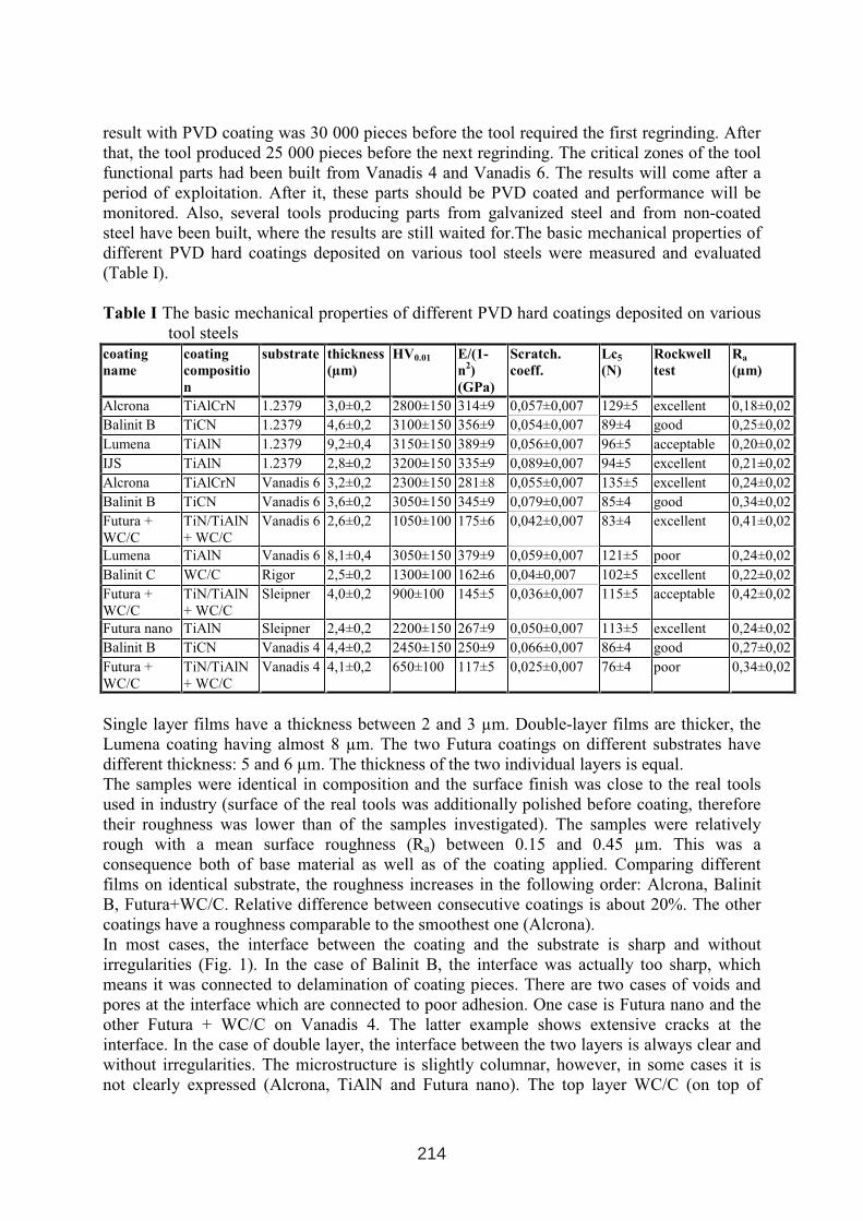
result with PVD coating was 30 000 pieces before the tool required the first regrinding. After
that, the tool produced 25 000 pieces before the next regrinding. The critical zones of the tool
functional parts had been built from Vanadis 4 and Vanadis 6. The results will come after a
period of exploitation. After it, these parts should be PVD coated and performance will be
monitored. Also, several tools producing parts from galvanized steel and from non-coated
steel have been built, where the results are still waited for.The basic mechanical properties of
different PVD hard coatings deposited on various tool steels were measured and evaluated
(Table I).
Table I The basic mechanical properties of different PVD hard coatings deposited on various
tool steels
coating
name
coating
compositio
n
substrate thickness
(µm)
HV0.01 E/(1-
n2)
(GPa)
Scratch.
coeff.
Lc5
(N)
Rockwell
test
Ra
(µm)
Alcrona TiAlCrN 1.2379 3,0±0,2 2800±150 314±9 0,057±0,007 129±5 excellent 0,18±0,02
Balinit B TiCN 1.2379 4,6±0,2 3100±150 356±9 0,054±0,007 89±4 good 0,25±0,02
Lumena TiAlN 1.2379 9,2±0,4 3150±150 389±9 0,056±0,007 96±5 acceptable 0,20±0,02
IJS TiAlN 1.2379 2,8±0,2 3200±150 335±9 0,089±0,007 94±5 excellent 0,21±0,02
Alcrona TiAlCrN Vanadis 6 3,2±0,2 2300±150 281±8 0,055±0,007 135±5 excellent 0,24±0,02
Balinit B TiCN Vanadis 6 3,6±0,2 3050±150 345±9 0,079±0,007 85±4 good 0,34±0,02
Futura +
WC/C
TiN/TiAlN
+ WC/C
Vanadis 6 2,6±0,2 1050±100 175±6 0,042±0,007 83±4 excellent 0,41±0,02
Lumena TiAlN Vanadis 6 8,1±0,4 3050±150 379±9 0,059±0,007 121±5 poor 0,24±0,02
Balinit C WC/C Rigor 2,5±0,2 1300±100 162±6 0,04±0,007 102±5 excellent 0,22±0,02
Futura +
WC/C
TiN/TiAlN
+ WC/C
Sleipner 4,0±0,2 900±100 145±5 0,036±0,007 115±5 acceptable 0,42±0,02
Futura nano TiAlN Sleipner 2,4±0,2 2200±150 267±9 0,050±0,007 113±5 excellent 0,24±0,02
Balinit B TiCN Vanadis 4 4,4±0,2 2450±150 250±9 0,066±0,007 86±4 good 0,27±0,02
Futura +
WC/C
TiN/TiAlN
+ WC/C
Vanadis 4 4,1±0,2 650±100 117±5 0,025±0,007 76±4 poor 0,34±0,02
Single layer films have a thickness between 2 and 3 µm. Double-layer films are thicker, the
Lumena coating having almost 8 µm. The two Futura coatings on different substrates have
different thickness: 5 and 6 µm. The thickness of the two individual layers is equal.
The samples were identical in composition and the surface finish was close to the real tools
used in industry (surface of the real tools was additionally polished before coating, therefore
their roughness was lower than of the samples investigated). The samples were relatively
rough with a mean surface roughness (Ra) between 0.15 and 0.45 µm. This was a
consequence both of base material as well as of the coating applied. Comparing different
films on identical substrate, the roughness increases in the following order: Alcrona, Balinit
B, Futura+WC/C. Relative difference between consecutive coatings is about 20%. The other
coatings have a roughness comparable to the smoothest one (Alcrona).
In most cases, the interface between the coating and the substrate is sharp and without
irregularities (Fig. 1). In the case of Balinit B, the interface was actually too sharp, which
means it was connected to delamination of coating pieces. There are two cases of voids and
pores at the interface which are connected to poor adhesion. One case is Futura nano and the
other Futura + WC/C on Vanadis 4. The latter example shows extensive cracks at the
interface. In the case of double layer, the interface between the two layers is always clear and
without irregularities. The microstructure is slightly columnar, however, in some cases it is
not clearly expressed (Alcrona, TiAlN and Futura nano). The top layer WC/C (on top of
214
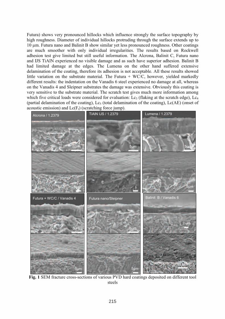
Futura) shows very pronounced hillocks which influence strongly the surface topography by
high roughness. Diameter of individual hillocks protruding through the surface extends up to
10 µm. Futura nano and Balinit B show similar yet less pronounced roughness. Other coatings
are much smoother with only individual irregularities. The results based on Rockwell
adhesion test give limited but still useful information. The Alcrona, Balinit C, Futura nano
and IJS TiAlN experienced no visible damage and as such have superior adhesion. Balinit B
had limited damage at the edges. The Lumena on the other hand suffered extensive
delamination of the coating, therefore its adhesion is not acceptable. All these results showed
little variation on the substrate material. The Futura + WC/C, however, yielded markedly
different results: the indentation on the Vanadis 6 steel experienced no damage at all, whereas
on the Vanadis 4 and Sleipner substrates the damage was extensive. Obviously this coating is
very sensitive to the substrate material. The scratch test gives much more information among
which five critical loads were considered for evaluation: Lc3 (flaking at the scratch edge), Lc4
(partial delamination of the coating), Lc5 (total delamination of the coating), Lc(AE) (onset of
acoustic emission) and Lc(Ft) (scratching force jump).
Fig. 1 SEM fracture cross-sections of various PVD hard coatings deposited on different tool
steels
µm
5µm
TiAlN IJS / 1.2379
5µm
5µm
Alcrona / 1.2379
5µm
5µm
Lumena / 1.2379
5µm
5µm
Futura nano/Sleipner
5µm
5µm
Futura + WC/C / Vanadis 4 Balinit B / Vanadis 6
2 µm
10 µm
215
The Lc3 and Lc5 correspond within a few Newtons, the other loads also generally correlate
well. The Alcrona coating proved superior to all the rest. The lowest critcal loads were
encountered at the Futura + WC/C, similar to the Rockwell results. Interestingly, the Lumena
performed much better than at the Rockwell results. The remaining coatings scored in-
between. Apart from the critical loads, the scratching coefficient was also compared. At 10 N
load, it is between 0.05 and 0.06. Lower values were obtained at lubricating coatings (WC/C)
and higher values at Balinit B and IJS TiAlN. Depth-sensing indentation was used to evaluate
mechanical properties. The maximum load was varied between 30 and 1000 mN. Too high
load causes the plastic zone to penetrate through the coating, while too low load brings much
scattering due to surface roughness. There was no optimal load as the thickness of the
coatings was not uniform, but in general 100 mN load was the most appropriate. At 100 mN
the highest hardness was obtained for IJS TiAlN (3200HV), which was very close to the other
TiAlN-based coatings (Alcrona, Lumena, Futura nano) and TiCN (Balinit B). The soft WC/C-
based lubricating coatings had a hardness between 650 and 1300 HV. The indentation
modulus E/(1–ν2) had a smiliar dependance as the hardness. It was around 350 GPa for
TiAlN- and TiCN-based coatings and around 150 GPa for WC/C-based coatings. The
variation of elastic deformation energy percentage did not vary that much, as it was mainly
limited between 50 and 60%.
4. CONCLUSION
In order to compare hard coatings for protection of forming tools a datatable of the most
important hard coating properties was set up. Based on mechanical properties measurements
of six different PVD hard coatings we found that the best adhesion was obtained for
TiCrAlN/1.2379 and TiCrAlN/Vanadis 6 combinations, the highest microhardnes for
TiAlN/1.2379, while the indentation modulus and scratching coefficient were the lowest for
WC/C hard coating.
AcknowledgementsThis work was supported by the Ministry of Education, Science and Sport of the Republic of
Slovenia and Ministry of the Economy. The authors would like to thank Zoran Samardžija for
SEM analyses and company Balzers GmbH, Kapfenberg from Austria for preparation of test
samples.
REFERENCE
1. C. Mitterer, F. Holler, D. Reitberger, E. Badisch, M. Stoiber, C. Lugmair, R. Nobauer, Th.
Muller, R. Kullmer, Surf. Coat. Technol. 163-164 (2003) 716-722
2. Uddeholm House Magazine (issued in Denmark), 2004.
3. B. Podgornik, S. Hogmark, O. Sandberg, V. Leskovšek, Wear 254 (2003) 1113-1121
4. P. Carlsson, M. Olsson, Surf. Coat. Technol. (in press)
5. P. Pesch, S. Santel, S. Woestmann, P. Masarczyk, K. Herden, T. Sticky, A. Martens, S. Uldrich,
H. Holleck, Surf. Coat. Technol., 163-164 (2003) 739-746
6. Y. Madorsky, M. Thompson, Proc. of 2nd annual Stamping Journal Forum, May 2004, Detroit
7. L. Careras, S. Bueno, F. Montala, Proc. of 7th Int. Conf. »Trends in the development of
Machinery and Associated Technology«, Barcelona, 2003
8. J. Vetter, R. Knaup, H. Dwuletzki, E. Schneider, S. Vogler, Surf. Coat. Technol. 86-87 (1996)
739-747)
9. J. Vetter, Surf. Coat. Technol. 76-77 (1995) 719-724
10. http://www.coating-guide.balzers.com
216
TESTS OF MATERIALS AND SURFACE TREATMENT TECHNOLOGIES ENHANCING THE LIFETIME OF FORMING TOOLS
Josef Fajt1, Zbigniew Łataś
2, Petr Motyčka
3, Zbigniew Rogalski
2, Pavel Šuchmann
3
1ŠKO-TOOLS s.r.o., Pilsen, Czech Republic
2Institut of Precision Mechanics, Warsaw, Poland3COMTES FHT s.r.o., Pilsen, Czech Republic
1. INTRODUCTION
The lifetime of forging dies is a very important factor affecting both the efficiency and
production costs in the forging industry. Especially in the production of large series of
forgings it is quite necessary to use more expensive tools with higher lifetime than that of
conventional tools. It is because the costs of frequent changing of tools (and interrupting of
production) are very high. That is why the forging plants invest large amounts of money in
solutions enhancing the lifetime of dies in last years.
The companies of COMTES FHT and ŠKO-TOOLS (both from Pilsen, Czech Republic)
together with the Institute of Precision Mechanics (Warsaw, Poland) cooperate very closely
on the development of forging dies and other forming tools with enhanced lifetime since
2004. Their research work is directed especially to innovative tool materials (modern hot
working steels, special ceramics, sintered carbides etc.), heat treatment and special surface
treatment technologies (cryogenic treatment, PVD and thermal sprayed coatings etc.). Some
results of this development are presented in the present article.
Keywords: forging dies, hot work tool steels, cryogenic treatment, surface modifications
2. TOOL MATERIALS AND SURFACE TREATMENT TECHNOLOGIES
The forging tools are stressed especially by high temperatures, which in some cases exceed
500 °C on the tool surface. This is combined with high mechanical loads (high partial presses,
dynamic stresses, etc.). The influence of the high temperatures is strengthened by fluctuation
of surface temperature depending of the nature of the forging process (the tool is getting in
contact with the hot material many times in short cycles). Thus, the hardness and strength at
high temperatures as well as the fatigue resistance and ductility are the most important
properties of forging tools.
2.1 Common and modern steels for forging dies
The chemical composition of the hot working steels is based mainly on addition of
molybdenum or nickel (which enhance the hardenability and temperature resistance) and
chromium, tungsten or other elements, which combine with carbon, thus creating hard
1 INTERNATIONAL CONFERENCE ON HEAT TREATMENT
AND SURFACE ENGINEERING OF TOOLS AND DIES
st
Pula, Croatia 08 - 11 June, 2005,
IFHTSE 2005
217
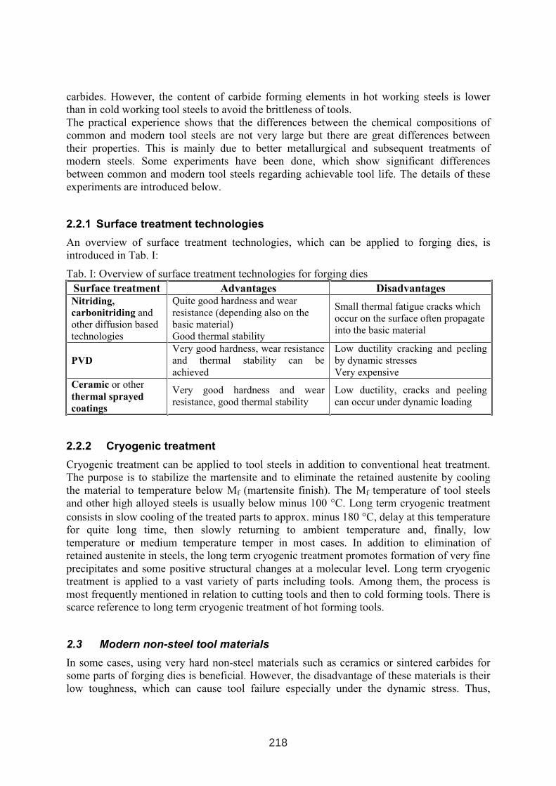
carbides. However, the content of carbide forming elements in hot working steels is lower
than in cold working tool steels to avoid the brittleness of tools.
The practical experience shows that the differences between the chemical compositions of
common and modern tool steels are not very large but there are great differences between
their properties. This is mainly due to better metallurgical and subsequent treatments of
modern steels. Some experiments have been done, which show significant differences
between common and modern tool steels regarding achievable tool life. The details of these
experiments are introduced below.
2.2.1 Surface treatment technologies
An overview of surface treatment technologies, which can be applied to forging dies, is
introduced in Tab. I:
Tab. I: Overview of surface treatment technologies for forging dies
Surface treatment Advantages DisadvantagesNitriding,
carbonitriding and
other diffusion based
technologies
Quite good hardness and wear
resistance (depending also on the
basic material)
Good thermal stability
Small thermal fatigue cracks which
occur on the surface often propagate
into the basic material
PVD
Very good hardness, wear resistance
and thermal stability can be
achieved
Low ductility cracking and peeling
by dynamic stresses
Very expensive
Ceramic or other
thermal sprayed
coatings
Very good hardness and wear
resistance, good thermal stability
Low ductility, cracks and peeling
can occur under dynamic loading
2.2.2 Cryogenic treatment
Cryogenic treatment can be applied to tool steels in addition to conventional heat treatment.
The purpose is to stabilize the martensite and to eliminate the retained austenite by cooling
the material to temperature below Mf (martensite finish). The Mf temperature of tool steels
and other high alloyed steels is usually below minus 100 °C. Long term cryogenic treatment
consists in slow cooling of the treated parts to approx. minus 180 °C, delay at this temperature
for quite long time, then slowly returning to ambient temperature and, finally, low
temperature or medium temperature temper in most cases. In addition to elimination of
retained austenite in steels, the long term cryogenic treatment promotes formation of very fine
precipitates and some positive structural changes at a molecular level. Long term cryogenic
treatment is applied to a vast variety of parts including tools. Among them, the process is
most frequently mentioned in relation to cutting tools and then to cold forming tools. There is
scarce reference to long term cryogenic treatment of hot forming tools.
2.3 Modern non-steel tool materials
In some cases, using very hard non-steel materials such as ceramics or sintered carbides for
some parts of forging dies is beneficial. However, the disadvantage of these materials is their
low toughness, which can cause tool failure especially under the dynamic stress. Thus,
218
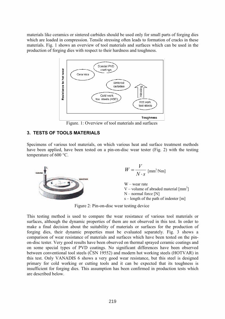
materials like ceramics or sintered carbides should be used only for small parts of forging dies
which are loaded in compression. Tensile stressing often leads to formation of cracks in these
materials. Fig. 1 shows an overview of tool materials and surfaces which can be used in the
production of forging dies with respect to their hardness and toughness.
Figure. 1: Overview of tool materials and surfaces
3. TESTS OF TOOLS MATERIALS
Specimens of various tool materials, on which various heat and surface treatment methods
have been applied, have been tested on a pin-on-disc wear tester (Fig. 2) with the testing
temperature of 600 °C.
sN
VW
⋅= [mm
3/Nm]
W – wear rate
V – volume of abraded material [mm3]
N – normal force [N]
s – length of the path of indenter [m]
Figure 2: Pin-on-disc wear testing device
This testing method is used to compare the wear resistance of various tool materials or
surfaces, although the dynamic properties of them are not observed in this test. In order to
make a final decision about the suitability of materials or surfaces for the production of
forging dies, their dynamic properties must be evaluated separately. Fig. 3 shows a
comparison of wear resistance of materials and surfaces which have been tested on the pin-
on-disc tester. Very good results have been observed on thermal sprayed ceramic coatings and
on some special types of PVD coatings. No significant differences have been observed
between conventional tool steels (ČSN 19552) and modern hot working steels (HOTVAR) in
this test. Only VANADIS 6 shows a very good wear resistance, but this steel is designed
primary for cold working or cutting tools and it can be expected that its toughness is
insufficient for forging dies. This assumption has been confirmed in production tests which
are described below.
219
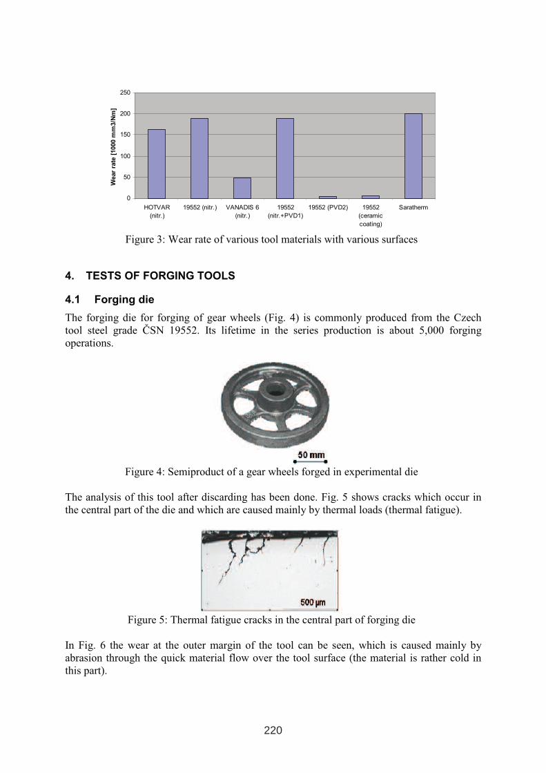
0
50
100
150
200
250
HOTVAR
(nitr.)
19552 (nitr.) VANADIS 6
(nitr.)
19552
(nitr.+PVD1)
19552 (PVD2) 19552
(ceramic
coating)
Saratherm
Wear
rate
[1000
mm
3/N
m]
Figure 3: Wear rate of various tool materials with various surfaces
4. TESTS OF FORGING TOOLS
4.1 Forging die
The forging die for forging of gear wheels (Fig. 4) is commonly produced from the Czech
tool steel grade ČSN 19552. Its lifetime in the series production is about 5,000 forging
operations.
Figure 4: Semiproduct of a gear wheels forged in experimental die
The analysis of this tool after discarding has been done. Fig. 5 shows cracks which occur in
the central part of the die and which are caused mainly by thermal loads (thermal fatigue).
Figure 5: Thermal fatigue cracks in the central part of forging die
In Fig. 6 the wear at the outer margin of the tool can be seen, which is caused mainly by
abrasion through the quick material flow over the tool surface (the material is rather cold in
this part).
220
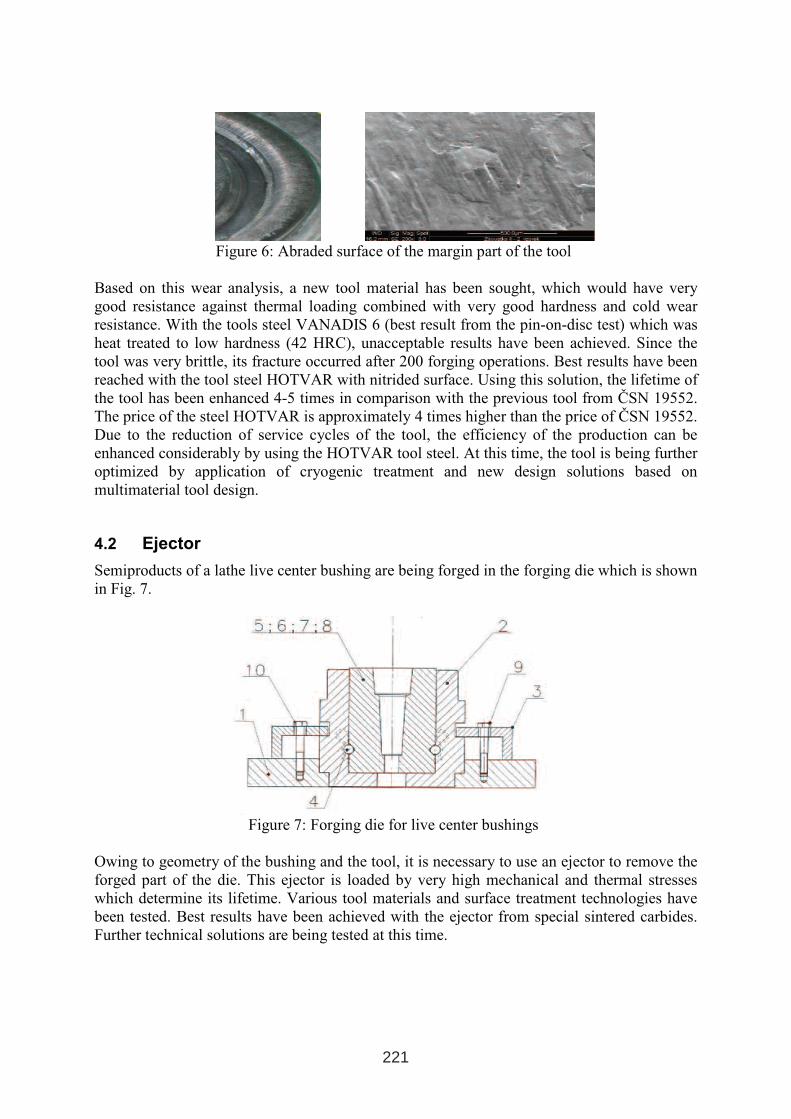
Figure 6: Abraded surface of the margin part of the tool
Based on this wear analysis, a new tool material has been sought, which would have very
good resistance against thermal loading combined with very good hardness and cold wear
resistance. With the tools steel VANADIS 6 (best result from the pin-on-disc test) which was
heat treated to low hardness (42 HRC), unacceptable results have been achieved. Since the
tool was very brittle, its fracture occurred after 200 forging operations. Best results have been
reached with the tool steel HOTVAR with nitrided surface. Using this solution, the lifetime of
the tool has been enhanced 4-5 times in comparison with the previous tool from ČSN 19552.
The price of the steel HOTVAR is approximately 4 times higher than the price of ČSN 19552.
Due to the reduction of service cycles of the tool, the efficiency of the production can be
enhanced considerably by using the HOTVAR tool steel. At this time, the tool is being further
optimized by application of cryogenic treatment and new design solutions based on
multimaterial tool design.
4.2 Ejector
Semiproducts of a lathe live center bushing are being forged in the forging die which is shown
in Fig. 7.
Figure 7: Forging die for live center bushings
Owing to geometry of the bushing and the tool, it is necessary to use an ejector to remove the
forged part of the die. This ejector is loaded by very high mechanical and thermal stresses
which determine its lifetime. Various tool materials and surface treatment technologies have
been tested. Best results have been achieved with the ejector from special sintered carbides.
Further technical solutions are being tested at this time.
221

4.3 Extrusion tool (ECAP)
Experimental cold extrusion tool for refinement of microstructure of metallic materials
through extremely high strain (ECAP) is shown in Fig. 8. To avoid the breakage and to
eliminate the abrasive wearing of the tool, new technical solutions are being sought. The main
target is to find a surface with low friction coefficient and high cold wear resistance. A special
PVD coating which has been developed for this purpose will be tested in upcoming months.
Figure 8: Experimental extrusion tool (ECAP)
ACKNOWLEDGEMENTS
The development of new technical solutions for enhancing the lifetime of forging dies is
being funded as a Eureka E!3030 FORMINGTOOLS project. The development of the
experimental extrusion tool (ECAP) is being supported by the Czech ministery of Education,
Youth and Sports as a part of a research project MSM 2631691901 aimed on refinement of
microstructures in metallic materials.
222
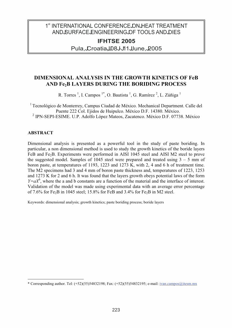
DIMENSIONAL ANALYSIS IN THE GROWTH KINETICS OF FeB
AND Fe2B LAYERS DURING THE BORIDING PROCESS
R. Torres1, I. Campos
1*, O. Bautista
1, G. Ramírez
2, L. Zúñiga
1
1Tecnológico de Monterrey, Campus Ciudad de México. Mechanical Department. Calle del
Puente 222 Col. Ejidos de Huipulco. México D.F. 14380. México. 2
IPN-SEPI-ESIME. U.P. Adolfo López Mateos, Zacatenco. México D.F. 07738. México
ABSTRACT
Dimensional analysis is presented as a powerful tool in the study of paste boriding. In
particular, a non dimensional method is used to study the growth kinetics of the boride layers
FeB and Fe2B. Experiments were performed in AISI 1045 steel and AISI M2 steel to prove
the suggested model. Samples of 1045 steel were prepared and treated using 3 – 5 mm of
boron paste, at temperatures of 1193, 1223 and 1273 K, with 2, 4 and 6 h of treatment time.
The M2 specimens had 3 and 4 mm of boron paste thickness and, temperatures of 1223, 1253
and 1273 K for 2 and 6 h. It was found that the layers growth obeys potential laws of the form
Y=aXb, where the a and b constants are a function of the material and the interface of interest.
Validation of the model was made using experimental data with an average error percentage
of 7.6% for Fe2B in 1045 steel; 15.8% for FeB and 3.4% for Fe2B in M2 steel.
Keywords: dimensional analysis; growth kinetics; paste boriding process; boride layers
* Corresponding author. Tel: (+52)(55)54832198; Fax: (+52)(55)54832195; e-mail: [email protected]
1 INTERNATIONAL CONFERENCE ON HEAT TREATMENT
AND SURFACE ENGINEERING OF TOOLS AND DIES
st
Pula, Croatia 08 - 11 June, 2005,
IFHTSE 2005
223
1. INTRODUCTION
Dimensional analysis is a method that reduces the number and complexity of experimental
variables affecting a physical problem, by using compacting techniques [1]. If a phenomenon
depends on n dimensional variables, dimensional analysis can reduce the problem to only k
dimensionless variables, where the subtraction n – k = 1, 2, 3, or 4 depends only on the
process complexity. Generally, n – k is equivalent to the number of fundamental dimensions
that govern the problem. One of the most important benefits of dimensional analysis is the
generation of a model, based on scaling laws, that groups every experimental aspect used
during the process. In the same way, it helps to predict the behavior of physical phenomena in
similar conditions, under the same experimentation range [2].
During this study, dimensional analysis was applied to the paste boriding process. Via this
surface hardening technique, boron atoms are diffused into the surface of several types of
ferrous and non-ferrous alloys. Thus, the formation of iron borides causes an increment of
engineering components exposed to corrosion and wear [3].
Inside the paste boriding process, there are three important parameters to be controlled: time,
temperature and the boron potential that surrounds the material surface. Boron potential is
closely related to the paste amount that covers the steel sample; as paste thickness increases,
boron diffusion velocity is greater over the formed phases in the surface [4]. In contrast, boron
potentials involved in the process can create two characteristic phases over the surface: Fe2B,
convenient for industrial applications; and the outermost phase, FeB. Also, these phases are
formed according to the present alloying elements in the material. It is more likely to have
Fe2B growth in low carbon and low alloy steels, with a serrated morphology. In contrast,
fronts of flat growth of a bi-phase FeB/Fe2B are formed when the substrate has an increment
in carbon and alloying elements [6]. This study considers the most important variables in the
paste boriding process; such as, boron paste thickness, treatment time, iron boride layer
thickness, growth constant, and boron concentration at the surface and at the FeB/Fe2B
interface. The purpose is to group these variables in a dimensionless form to generate a
tentative model containing the experiments carried out at work temperatures. The validity of
the model is done in AISI 1045 and M2 steels, (under different experimental conditions)
where the main influence is given by the boron paste thickness.
2. MODEL
2.1 Non-dimensional method
The independent and dependent parameter units are defined as: u [L] indicating average
thickness of layer FeB and Fe2B; t [T] corresponding to treatment time; ho [L] equivalent to
an initial amount of boron paste over the substrate surface; growth constant defined as
k [LcT
-1]; and Cs and Co with units of the form [ML
-3] are described as the boron
concentration over the material surface and in present interphases. Dimensionless numbers are
found through the classical method application of a dimensionless solution, as proposed in
reference [1]. For the first dimensionless parameter (∏ 1), the terms ho, t, Cs and u are
grouped, resulting in the following expression:
( )0003 TLMLMLTL
ZYX=
− (1)
where x = -1 , y = 0 , z = 0. Finally, according to (1), the dimensionless parameter ∏ 1 is
defined as:
224
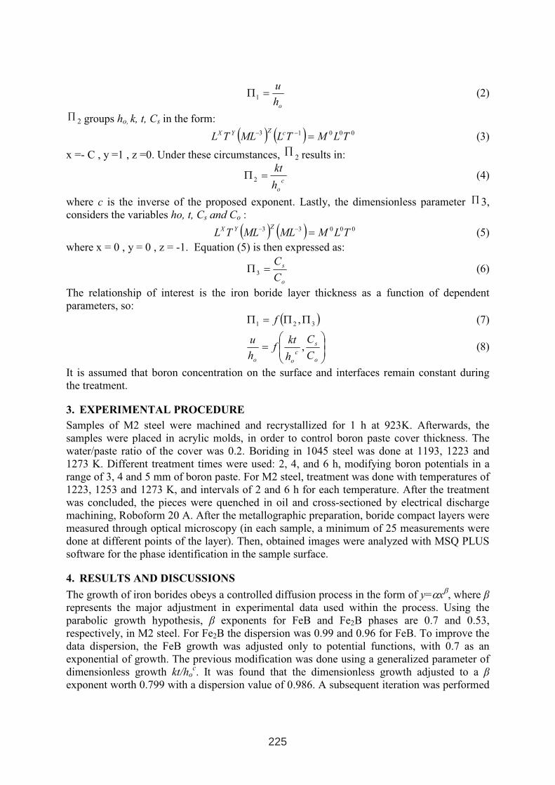
oh
u=Π1 (2)
∏2 groups ho, k, t, Cs in the form:
( ) ( )00013 TLMTLMLTL cZYX
=−− (3)
x =- C , y =1 , z =0. Under these circumstances, ∏ 2 results in:
c
oh
kt=Π 2 (4)
where c is the inverse of the proposed exponent. Lastly, the dimensionless parameter ∏ 3,
considers the variables ho, t, Cs and Co :
( ) ( )00033 TLMMLMLTL
ZYX=
−− (5)
where x = 0 , y = 0 , z = -1. Equation (5) is then expressed as:
o
s
C
C=Π 3 (6)
The relationship of interest is the iron boride layer thickness as a function of dependent
parameters, so:
( )321 ,ΠΠ=Π f (7)
=
o
s
c
oo C
C
h
ktf
h
u, (8)
It is assumed that boron concentration on the surface and interfaces remain constant during
the treatment.
3. EXPERIMENTAL PROCEDURE
Samples of M2 steel were machined and recrystallized for 1 h at 923K. Afterwards, the
samples were placed in acrylic molds, in order to control boron paste cover thickness. The
water/paste ratio of the cover was 0.2. Boriding in 1045 steel was done at 1193, 1223 and
1273 K. Different treatment times were used: 2, 4, and 6 h, modifying boron potentials in a
range of 3, 4 and 5 mm of boron paste. For M2 steel, treatment was done with temperatures of
1223, 1253 and 1273 K, and intervals of 2 and 6 h for each temperature. After the treatment
was concluded, the pieces were quenched in oil and cross-sectioned by electrical discharge
machining, Roboform 20 A. After the metallographic preparation, boride compact layers were
measured through optical microscopy (in each sample, a minimum of 25 measurements were
done at different points of the layer). Then, obtained images were analyzed with MSQ PLUS
software for the phase identification in the sample surface.
4. RESULTS AND DISCUSSIONS
The growth of iron borides obeys a controlled diffusion process in the form of y=αxβ, where β
represents the major adjustment in experimental data used within the process. Using the
parabolic growth hypothesis, β exponents for FeB and Fe2B phases are 0.7 and 0.53,
respectively, in M2 steel. For Fe2B the dispersion was 0.99 and 0.96 for FeB. To improve the
data dispersion, the FeB growth was adjusted only to potential functions, with 0.7 as an
exponential of growth. The previous modification was done using a generalized parameter of
dimensionless growth kt/hoc. It was found that the dimensionless growth adjusted to a β
exponent worth 0.799 with a dispersion value of 0.986. A subsequent iteration was performed
225
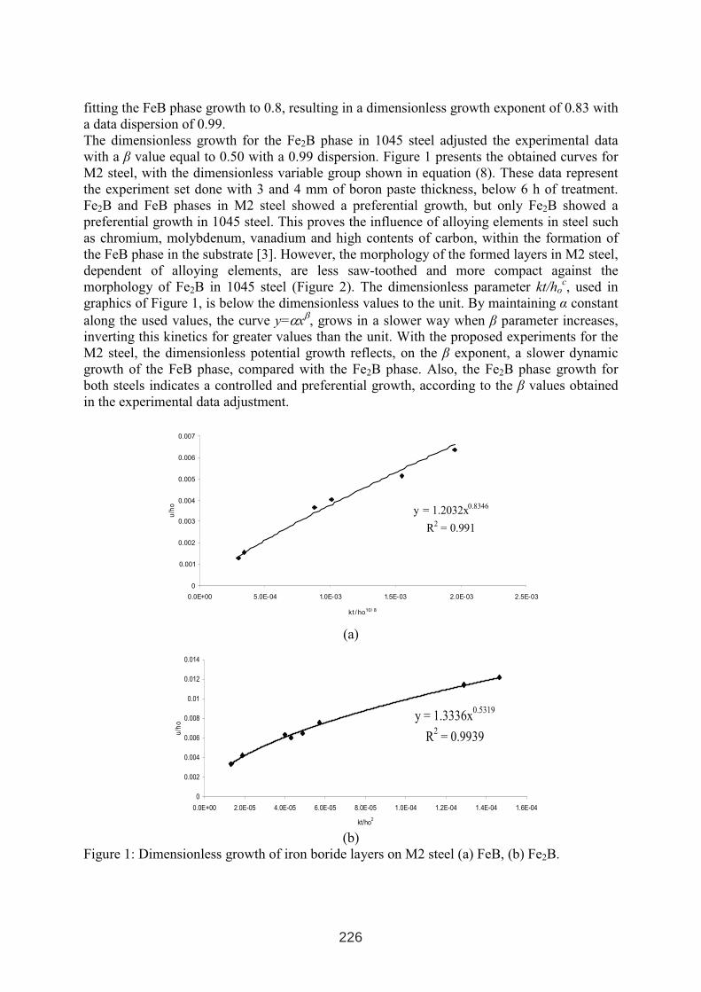
fitting the FeB phase growth to 0.8, resulting in a dimensionless growth exponent of 0.83 with
a data dispersion of 0.99.
The dimensionless growth for the Fe2B phase in 1045 steel adjusted the experimental data
with a β value equal to 0.50 with a 0.99 dispersion. Figure 1 presents the obtained curves for
M2 steel, with the dimensionless variable group shown in equation (8). These data represent
the experiment set done with 3 and 4 mm of boron paste thickness, below 6 h of treatment.
Fe2B and FeB phases in M2 steel showed a preferential growth, but only Fe2B showed a
preferential growth in 1045 steel. This proves the influence of alloying elements in steel such
as chromium, molybdenum, vanadium and high contents of carbon, within the formation of
the FeB phase in the substrate [3]. However, the morphology of the formed layers in M2 steel,
dependent of alloying elements, are less saw-toothed and more compact against the
morphology of Fe2B in 1045 steel (Figure 2). The dimensionless parameter kt/hoc, used in
graphics of Figure 1, is below the dimensionless values to the unit. By maintaining α constant
along the used values, the curve y=αxβ, grows in a slower way when β parameter increases,
inverting this kinetics for greater values than the unit. With the proposed experiments for the
M2 steel, the dimensionless potential growth reflects, on the β exponent, a slower dynamic
growth of the FeB phase, compared with the Fe2B phase. Also, the Fe2B phase growth for
both steels indicates a controlled and preferential growth, according to the β values obtained
in the experimental data adjustment.
y = 1.2032x0.8346
R2
= 0.991
0
0.001
0.002
0.003
0.004
0.005
0.006
0.007
0.0E+00 5.0E-04 1.0E-03 1.5E-03 2.0E-03 2.5E-03
kt / ho10/ 8
(a)
y = 1.3336x0.5319
R2
= 0.9939
0
0.002
0.004
0.006
0.008
0.01
0.012
0.014
0.0E+00 2.0E-05 4.0E-05 6.0E-05 8.0E-05 1.0E-04 1.2E-04 1.4E-04 1.6E-04
kt/ho2
u/h
o
(b)
Figure 1: Dimensionless growth of iron boride layers on M2 steel (a) FeB, (b) Fe2B.
226
u/h
o
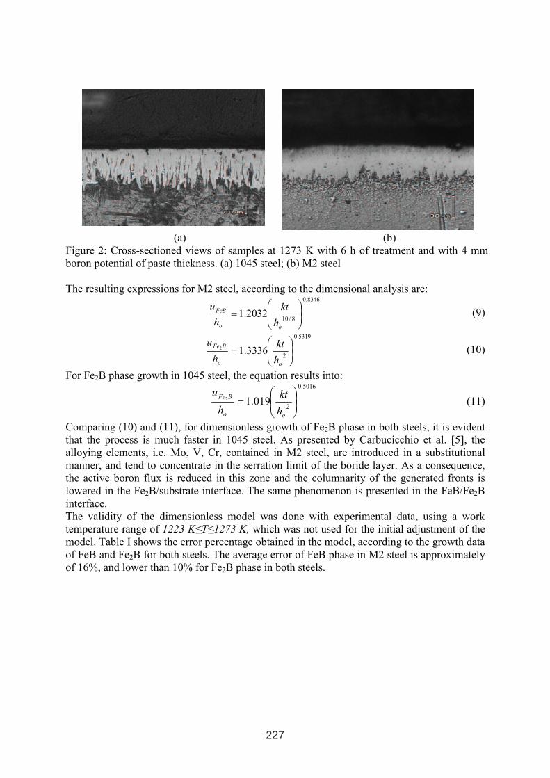
(a) (b)
Figure 2: Cross-sectioned views of samples at 1273 K with 6 h of treatment and with 4 mm
boron potential of paste thickness. (a) 1045 steel; (b) M2 steel
The resulting expressions for M2 steel, according to the dimensional analysis are:8346.0
8/102032.1
=
oo
FeB
h
kt
h
u(9)
5319.0
23336.12
=
oo
BFe
h
kt
h
u(10)
For Fe2B phase growth in 1045 steel, the equation results into: 5016.0
2019.12
=
oo
BFe
h
kt
h
u(11)
Comparing (10) and (11), for dimensionless growth of Fe2B phase in both steels, it is evident
that the process is much faster in 1045 steel. As presented by Carbucicchio et al. [5], the
alloying elements, i.e. Mo, V, Cr, contained in M2 steel, are introduced in a substitutional
manner, and tend to concentrate in the serration limit of the boride layer. As a consequence,
the active boron flux is reduced in this zone and the columnarity of the generated fronts is
lowered in the Fe2B/substrate interface. The same phenomenon is presented in the FeB/Fe2B
interface.
The validity of the dimensionless model was done with experimental data, using a work
temperature range of 1223 K≤T≤1273 K, which was not used for the initial adjustment of the
model. Table I shows the error percentage obtained in the model, according to the growth data
of FeB and Fe2B for both steels. The average error of FeB phase in M2 steel is approximately
of 16%, and lower than 10% for Fe2B phase in both steels.
227
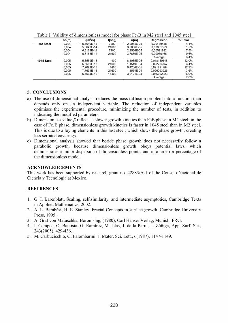
Table I: Validity of dimensionless model for phase Fe2B in M2 steel and 1045 steel ho[m] k[m
2/s] t[seg] u[m] Regression % Error
M2 Steel 0,0040,0040,0040,004
5,6640E-14 5,6640E-14 6,6168E-14 6,6168E-14
7200 21600 7200 21600
2,0044E-05 3,5006E-05 2,2566E-05 3,7660E-05
0,00480458 0,00861859 0,00521882 0,00936166
Average
4,1% 1,5% 7,5% 0,6% 3,4%
1045 Steel 0,0050,0050,0050,0050,005
5,6569E-13 5,6569E-13 7,7691E-13 7,7691E-13 5,4564E-12
14400 21600 14400 21600 14400
8,1065E-05 1,1519E-04 9,4234E-05 1,3534E-04 3,0121E-04
0,018159148 0,022254757 0,021291784 0,026093926 0,056602323
Average
12,0% 3,4%
12,9% 3,6% 6,0% 7,6%
5. CONCLUSIONS
a) The use of dimensional analysis reduces the mass diffusion problem into a function than
depends only on an independent variable. The reduction of independent variables
optimises the experimental procedure, minimizing the number of tests, in addition to
indicating the modified parameters.
b) Dimensionless value β reflects a slower growth kinetics than FeB phase in M2 steel; in the
case of Fe2B phase, dimensionless growth kinetics is faster in 1045 steel than in M2 steel.
This is due to alloying elements in this last steel, which slows the phase growth, creating
less serrated coverings.
c) Dimensional analysis showed that boride phase growth does not necessarily follow a
parabolic growth, because dimensionless growth obeys potential laws, which
demonstrates a minor dispersion of dimensionless points, and into an error percentage of
the dimensionless model.
ACKNOWLEDGEMENTS
This work has been supported by research grant no. 42883/A-1 of the Consejo Nacional de
Ciencia y Tecnologia at Mexico.
REFERENCES
1. G. I. Barenblatt, Scaling, self.similarity, and intermediate asymptotics, Cambridge Texts
in Applied Mathematics, 2002.
2. A. L. Barabási, H. E. Stanley, Fractal Concepts in surface growth, Cambridge University
Press, 1995.
3. A. Graf von Matuschka, Boronising, (1980), Carl Hanser Verlag, Munich, FRG.
4. I. Campos, O. Bautista, G. Ramírez, M. Islas, J. de la Parra, L. Zúñiga, App. Surf. Sci.,
243(2005), 429-436.
5. M. Carbucicchio, G. Palombarini, J. Mater. Sci. Lett., 6(1987), 1147-1149.
228
THERMAL AND THERMOCHEMICAL TREATMENT
OF TOOL STEELS IN VACUUM
Ventseslav Toshkov, Angel Ziumbilev,
Technical University of Sofia, Department of Material Engineering, Plovdiv Branch, Sofija,
Bulgaria
ABSTRACT
The aim of present work is to determine the complex influence of the preliminary heat
treatment in vacuum and nitriding in glow discharge on the service durability of hot working
tool steels – BH 11 (BS 4659) and BH21 (BS 4659).
The joint effect of vacuum heat treatment (annealing, quenching and high tempering at 600,
650, and 700 °C) and nitriding in low-temperature plasma on the wear resistance, surface
roughness, mechanical or thermal fatigue life, and fracture toughness (KQ) of the materials,
respectively machine parts and tools, has been studied.
Results obtained demonstrate the positive impact of ion nitriding, which depends on the
preliminary structure formed after various heat treatments.
Keywords: vacuum, ion nitriding, tool steels, wear resistance, fatigue, surface roughness
1. INTRODUCTION
Tools for metal working in hot state (forging and pressing dies for as well as dies for pressure
casting) operate under very heavy conditions, namely under short-duration or continuous heat
and power actions. For this reason, the tools material is subject to requirements for high
strength and heat resistance that will guarantee the necessary resistance against thermal
fatigue and plastic deformation of working layer at heating up to 500 – 700 °C.
Heat resistance is defined either by the temperature at which Rm ≥ 900 - 1000 MPa, or by the
temperature at which steels maintain a hardness of 45 - 50 HRC and sufficient fatigue
strength. At a hardness of 45 HRC the toughness should be not lesser than 0.3 MJ/m2
at 20 °C
and not lesser than 0.5 MJ/m2
at the operating temperature. Here, it should be also added
requirements for high wear resistance, contact endurance limit of working surfaces, resistance
against the formation of surface cracks in multifold heating and cooling, chemical resistance
in interacting with worked materials, good hardenability, and high coefficient of thermal
conductivity.
The objective of present work consists in studying the influence of the heat treatment in
vacuum and nitriding in glow discharge on some operational characteristics as the critical
coefficient of stress intensity KQ, fatigue limit, the thermal fatigue resistance, wear resistance
and surface roughness of hot-work tool steels, respectively machine parts and tools.
1 INTERNATIONAL CONFERENCE ON HEAT TREATMENT
AND SURFACE ENGINEERING OF TOOLS AND DIES
st
Pula, Croatia 08 - 11 June, 2005,
IFHTSE 2005
229
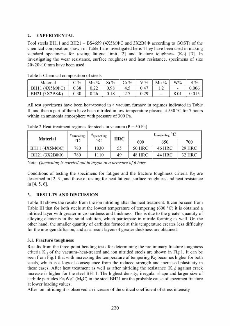
2. EXPERIMENTAL
Tool steels BH11 and BH21 – BS4659 (4Х5MФС and 3Х2В8Ф according to GOST) of the
chemical composition shown in Table I are investigated here. They have been used in making
standard specimens for testing fatigue limit [2] and fracture toughness (KQ) [3]. In
investigating the wear resistance, surface roughness and heat resistance, specimens of size
20×20×10 mm have been used.
Table I: Chemical composition of steels
Material C % Mn % Si % Cr % V % Mo % W% S %
BH11 (4Х5MФС) 0.38 0.22 0.98 4.5 0.47 1.2 - 0.006
BH21 (3Х2В8Ф) 0.30 0.26 0.18 2.7 0.29 - 8.01 0.015
All test specimens have been heat-treated in a vacuum furnace in regimes indicated in Table
II, and then a part of them have been nitrided in low-temperature plasma at 530 °C for 7 hours
within an ammonia atmosphere with pressure of 300 Pa.
Table 2 Heat-treatment regimes for steels in vacuum (P = 50 Pa)
ttempering, °°CMaterial
tannealing
°°C
tquenching
°°C HRC 600 650 700
BH11 (4Х5MФС) 780 1030 55 50 HRC 46 HRC 29 HRC
BH21 (3Х2В8Ф) 780 1110 49 48 HRC 44 HRC 32 HRC
Note: Quenching is carried out in argon at a pressure of 6 barr
Conditions of testing the specimens for fatigue and the fracture toughness criteria KQ are
described in [2, 3], and those of testing for heat fatigue, surface roughness and heat resistance
in [4, 5, 6].
3. RESULTS AND DISCUSSION
Table III shows the results from the ion nitriding after the heat treatment. It can be seen from
Table III that for both steels at the lowest temperature of tempering (600 °C) it is obtained a
nitrided layer with greater microhardness and thickness. This is due to the greater quantity of
alloying elements in the solid solution, which participate in nitride forming as well. On the
other hand, the smaller quantity of carbides formed at this temperature creates less difficulty
for the nitrogen diffusion, and as a result layers of greater thickness are obtained.
3.1. Fracture toughness
Results from the three-point bending tests for determining the preliminary fracture toughness
criteria KQ of the vacuum–heat-treated and ion nitrided steels are shown in Fig.1. It can be
seen from Fig.1 that with increasing the temperature of tempering KQ becomes higher for both
steels, which is a logical consequence from the reduced strength and increased plasticity in
these cases. After heat treatment as well as after nitriding the resistance (KQ) against crack
increase is higher for the steel BH11. The highest density, irregular shape and larger size of
carbide particles Fe3W3C (M6C) in the steel BH21 are the probable cause of specimen fracture
at lower loading values.
After ion nitriding it is observed an increase of the critical coefficient of stress intensity
230
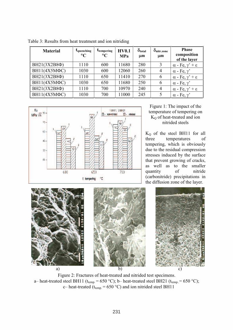
Table 3: Results from heat treatment and ion nitriding
Material tquenching
°°C
ttempering
°°CHV0.1MPa
δδtotal
µµm
δδnitr.zone
µµm
Phase
composition
of the layer
BH21(3Х2В8Ф) 1110 600 11680 280 3 α - Fe, γ’ + ε
BH11(4Х5MФС) 1030 600 12060 260 4 α - Fe, γ’BH21(3Х2В8Ф) 1110 650 11410 270 6 α - Fe, γ’ + ε
BH11(4Х5MФС) 1030 650 11680 250 6 α - Fe, γ’BH21(3Х2В8Ф) 1110 700 10970 240 4 α - Fe, γ’ + ε
BH11(4Х5MФС) 1030 700 11000 245 5 α - Fe, γ’
Figure 1: The impact of the
temperature of tempering on
KQ of heat-treated and ion
nitrided steels
KQ of the steel BH11 for all
three temperatures of
tempering, which is obviously
due to the residual compression
stresses induced by the surface
that prevent growing of cracks,
as well as to the smaller
quantity of nitride
(carbonitride) precipitations in
the diffusion zone of the layer.
a) b) c)
Figure 2: Fractures of heat-treated and nitrided test specimens.
a– heat-treated steel BH11 (ttemp. = 650 °C); b– heat-treated steel BH21 (ttemp..= 650 °C);
c– heat-treated (ttemp. = 650 °C) and ion nitrided steel BH11
231
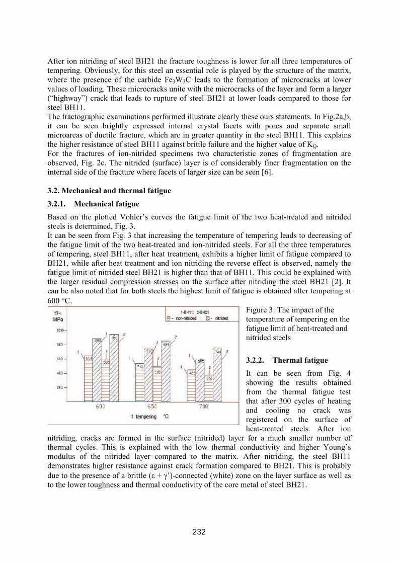
After ion nitriding of steel BH21 the fracture toughness is lower for all three temperatures of
tempering. Obviously, for this steel an essential role is played by the structure of the matrix,
where the presence of the carbide Fe3W3C leads to the formation of microcracks at lower
values of loading. These microcracks unite with the microcracks of the layer and form a larger
(“highway”) crack that leads to rupture of steel BH21 at lower loads compared to those for
steel BH11.
The fractographic examinations performed illustrate clearly these ours statements. In Fig.2a,b,
it can be seen brightly expressed internal crystal facets with pores and separate small
microareas of ductile fracture, which are in greater quantity in the steel BH11. This explains
the higher resistance of steel BH11 against brittle failure and the higher value of KQ.
For the fractures of ion-nitrided specimens two characteristic zones of fragmentation are
observed, Fig. 2c. The nitrided (surface) layer is of considerably finer fragmentation on the
internal side of the fracture where facets of larger size can be seen [6].
3.2. Mechanical and thermal fatigue
3.2.1. Mechanical fatigue
Based on the plotted Vohler’s curves the fatigue limit of the two heat-treated and nitrided
steels is determined, Fig. 3.
It can be seen from Fig. 3 that increasing the temperature of tempering leads to decreasing of
the fatigue limit of the two heat-treated and ion-nitrided steels. For all the three temperatures
of tempering, steel BH11, after heat treatment, exhibits a higher limit of fatigue compared to
BH21, while after heat treatment and ion nitriding the reverse effect is observed, namely the
fatigue limit of nitrided steel BH21 is higher than that of BH11. This could be explained with
the larger residual compression stresses on the surface after nitriding the steel BH21 [2]. It
can be also noted that for both steels the highest limit of fatigue is obtained after tempering at
600 °C.
Figure 3: The impact of the
temperature of tempering on the
fatigue limit of heat-treated and
nitrided steels
3.2.2. Thermal fatigue
It can be seen from Fig. 4
showing the results obtained
from the thermal fatigue test
that after 300 cycles of heating
and cooling no crack was
registered on the surface of
heat-treated steels. After ion
nitriding, cracks are formed in the surface (nitrided) layer for a much smaller number of
thermal cycles. This is explained with the low thermal conductivity and higher Young’s
modulus of the nitrided layer compared to the matrix. After nitriding, the steel BH11
demonstrates higher resistance against crack formation compared to BH21. This is probably
due to the presence of a brittle (ε + γ’)-connected (white) zone on the layer surface as well as
to the lower toughness and thermal conductivity of the core metal of steel BH21.
232
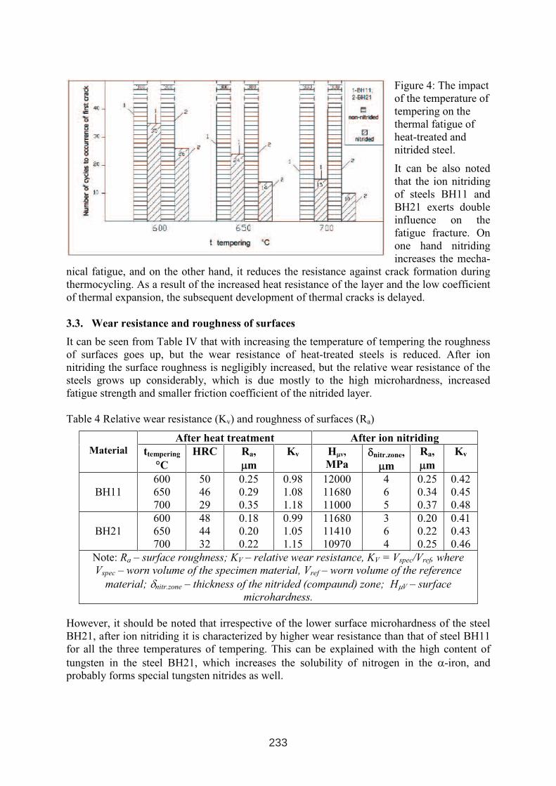
Figure 4: The impact
of the temperature of
tempering on the
thermal fatigue of
heat-treated and
nitrided steel.
It can be also noted
that the ion nitriding
of steels BH11 and
BH21 exerts double
influence on the
fatigue fracture. On
one hand nitriding
increases the mecha-
nical fatigue, and on the other hand, it reduces the resistance against crack formation during
thermocycling. As a result of the increased heat resistance of the layer and the low coefficient
of thermal expansion, the subsequent development of thermal cracks is delayed.
3.3. Wear resistance and roughness of surfaces
It can be seen from Table IV that with increasing the temperature of tempering the roughness
of surfaces goes up, but the wear resistance of heat-treated steels is reduced. After ion
nitriding the surface roughness is negligibly increased, but the relative wear resistance of the
steels grows up considerably, which is due mostly to the high microhardness, increased
fatigue strength and smaller friction coefficient of the nitrided layer.
Table 4 Relative wear resistance (Kv) and roughness of surfaces (Ra)
After heat treatment After ion nitriding Material ttempering
°°C
HRC Ra,
µµm
Kv Hµµv,
MPaδδnitr.zone,
µµm
Ra,
µµm
Kv
BH11
600
650
700
50
46
29
0.25
0.29
0.35
0.98
1.08
1.18
12000
11680
11000
4
6
5
0.25
0.34
0.37
0.42
0.45
0.48
BH21
600
650
700
48
44
32
0.18
0.20
0.22
0.99
1.05
1.15
11680
11410
10970
3
6
4
0.20
0.22
0.25
0.41
0.43
0.46
Note: Ra – surface roughness; KV – relative wear resistance, KV = Vspec/Vref, where
Vspec – worn volume of the specimen material, Vref – worn volume of the reference
material; δnitr.zone – thickness of the nitrided (compaund) zone; HµV – surface
microhardness.
However, it should be noted that irrespective of the lower surface microhardness of the steel
BH21, after ion nitriding it is characterized by higher wear resistance than that of steel BH11
for all the three temperatures of tempering. This can be explained with the high content of
tungsten in the steel BH21, which increases the solubility of nitrogen in the α-iron, and
probably forms special tungsten nitrides as well.
233
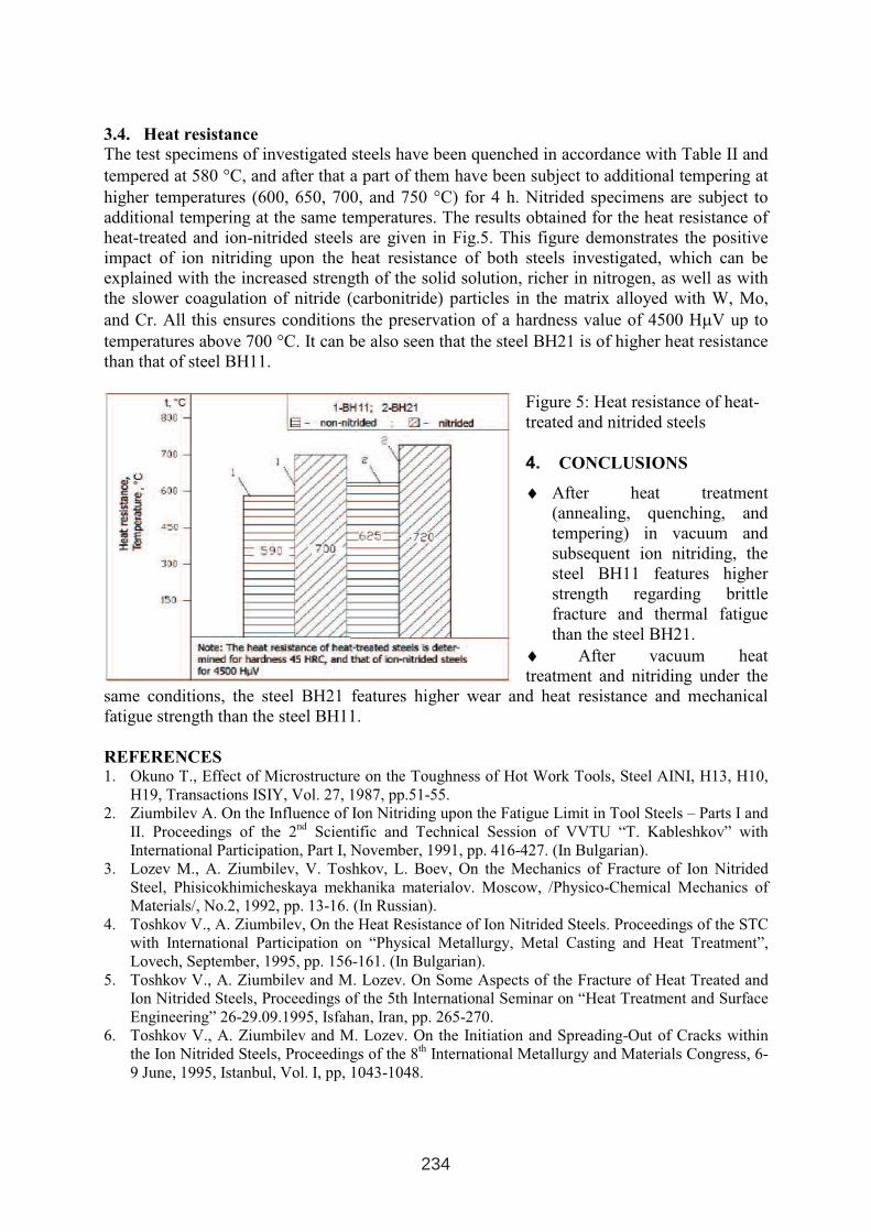
3.4. Heat resistance
The test specimens of investigated steels have been quenched in accordance with Table II and
tempered at 580 °C, and after that a part of them have been subject to additional tempering at
higher temperatures (600, 650, 700, and 750 °C) for 4 h. Nitrided specimens are subject to
additional tempering at the same temperatures. The results obtained for the heat resistance of
heat-treated and ion-nitrided steels are given in Fig.5. This figure demonstrates the positive
impact of ion nitriding upon the heat resistance of both steels investigated, which can be
explained with the increased strength of the solid solution, richer in nitrogen, as well as with
the slower coagulation of nitride (carbonitride) particles in the matrix alloyed with W, Mo,
and Cr. All this ensures conditions the preservation of a hardness value of 4500 HµV up to
temperatures above 700 °C. It can be also seen that the steel BH21 is of higher heat resistance
than that of steel BH11.
Figure 5: Heat resistance of heat-
treated and nitrided steels
4. CONCLUSIONS
♦♦ After heat treatment
(annealing, quenching, and
tempering) in vacuum and
subsequent ion nitriding, the
steel BH11 features higher
strength regarding brittle
fracture and thermal fatigue
than the steel BH21.
♦♦ After vacuum heat
treatment and nitriding under the
same conditions, the steel BH21 features higher wear and heat resistance and mechanical
fatigue strength than the steel BH11.
REFERENCES1. Okuno T., Effect of Microstructure on the Toughness of Hot Work Tools, Steel AINI, H13, H10,
H19, Transactions ISIY, Vol. 27, 1987, pp.51-55.
2. Ziumbilev A. On the Influence of Ion Nitriding upon the Fatigue Limit in Tool Steels – Parts І and
ІІ. Proceedings of the 2nd
Scientific and Technical Session of VVTU “T. Kableshkov” with
International Participation, Part І, November, 1991, pp. 416-427. (In Bulgarian).
3. Lozev M., A. Ziumbilev, V. Toshkov, L. Boev, On the Mechanics of Fracture of Ion Nitrided
Steel, Phisicokhimicheskaya mekhanika materialov. Moscow, /Physico-Chemical Mechanics of
Materials/, No.2, 1992, pp. 13-16. (In Russian).
4. Toshkov V., A. Ziumbilev, On the Heat Resistance of Ion Nitrided Steels. Proceedings of the STC
with International Participation on “Physical Metallurgy, Metal Casting and Heat Treatment”,
Lovech, September, 1995, pp. 156-161. (In Bulgarian).
5. Toshkov V., A. Ziumbilev and M. Lozev. On Some Aspects of the Fracture of Heat Treated and
Ion Nitrided Steels, Proceedings of the 5th International Seminar on “Heat Treatment and Surface
Engineering” 26-29.09.1995, Isfahan, Iran, pp. 265-270.
6. Toshkov V., A. Ziumbilev and M. Lozev. On the Initiation and Spreading-Out of Cracks within
the Ion Nitrided Steels, Proceedings of the 8th International Metallurgy and Materials Congress, 6-
9 June, 1995, Istanbul, Vol. I, pp, 1043-1048.
234
DUPLEX LAYERS ON COLD WORKING STEEL
Škorić B.1, Kakaš D.
1, Krumes D.
2, Kolumbić Z.
2
1University of Novi Sad, FTN, Trg D. Obradovica 6
2University of Osijek, Faculty of Mechanical Engineering, Slavonski Brod
ABSTRACT
In this paper the influence of plasma nitriding on quality of duplex coatings at cold working
steel was investigated. Classical plasma process and low pressure process are compared. After
plasma nitriding the different type of surface layers were deposited– TiN, TiAlN. Wear
resistance was investigated by "on line" measuring and acquired results are contact
temperature at tribological surface and coefficient of friction. Structure of surface and
morphology of wear zone were investigated by SEM.
1. INTRODUCTION
Plasma nitriding of cold working tools was the central point of our investigation in the middle
of 1980’s. [1, 2]. We could improve the tool life approximately 3 times this way. At the same
time a new technology called PVD for deposition of hard coatings appears, and our first
results connect with duplex layers were published in 1991 [3]. At the beginning the best
results that duplex coatings could get were with application on relatively soft base materials
like harden able Cr-Mo steel for gears and shafts. Our investigation shows that duplex
coatings could be applied very successfully on different types of tool steels [4]. During the
following investigation it was found that the choice of parameters and type of processes used
for realization of complex surface layers has a very important influence on duplex layers [5].
Today it is well known that duplex layers could be produced with different technologies and
different composition. A very popular technology is plasma nitriding (PN) and subsequent
deposition of hard coatings. Depending of exploitation conditions of the tool and type of steel
used excellent results could be obtained by plasma nitriding and PVD deposition of TiN or
CrN (PN/TiN or PN/CrN). Very important parameters are:
a) base material:
- composition,
- surface roughness,
- structure (heat treatment),
- morphology (shape),
- dimension etc.
1 INTERNATIONAL CONFERENCE ON HEAT TREATMENT
AND SURFACE ENGINEERING OF TOOLS AND DIES
st
Pula, Croatia 08 - 11 June, 2005,
IFHTSE 2005
235
b) plasma nitriding:
- technology (normal pressure, low pressure, plasma immersion etc.),
- temperature of process,
- hardness distribution,
- type of surface layers (compound , only diffusion zone etc),
- thickness of nitride layer,
- residual stresses etc.
c) hard coating deposition:
- technology (PVD, CVD, IBAD etc),
- type of interface,
- type of coating (TiN, CrN, TiAlN, DLC etc),
- surface hardness,
- surface roughness,
- preferred orientation,
- adhesion,
- composition and microstructure,
- coefficient of friction etc.
In this paper, some results from investigation of duplex layer deposited at cold working steel
will be presented.
2. EXPERIMENTAL
Cold working steel with the following chemical composition: 0,6 %C, 1,0 %Cr, 0,6 %Si, 0,2
%V was used. Steel was quenched from 860 ºC in oil and tempered at a little bit higher
temperature than usual for this type of steel, respecting the temperature for plasma nitriding.
Tempering was done at 500 ºC therefore we had reached a somewhat lower surface hardness
of 530 HV.
Plasma nitriding (PN) was provided in MONO 5 equipment at Electro technical faculty–
Belgrade. The main parameters are: substrate temperature 450 ºC, pressure 4 mbar, time 60
minute, gas composition N2– H2 (6 % of nitrogen).
Low pressure plasma nitriding (LpPN) was done on the Z 700 Laybold Heraus equipment at a
pressure of 5 Pa with the same time and temperature as used in PN process. Gas flow–
fAr=500 scm3min
-1, fH2=100 scm
3min
-1, fN2=80-150 scm
3min
-1. Voltage 2 kV and current
density 1,5 mAcm-2
were used.
The deposition of TiN was provided with parameters as follows: magnetron cathode power
Pc=5.4 kW, bias voltage Ub=-105 V, current density Ib=1 mA/cm2, argon flow rate fAr=164
scm3min
-1and nitrogen flow rate fN2=36 scm
3min
-1.
The deposition of TiAlN was provided with parameters as follows: magnetron cathode power
Pc=3,8 kW, bias voltage Ub=-110 V, current density Ib=1 mA/cm2, argon flow rate fAr=225
scm3min
-1and nitrogen flow rate fN2=39 scm
3min
-1.
Deposition of TiN and TiAlN was provided at the same installation as LpPN, consequently
after low pressure plasma nitriding. The other samples were cleaned and prepared for PVD
deposition after plasma nitriding.
The tribological behaviour of the coatings was studied by means of pin-on-ring contact
configuration in dry sliding conditions. Special test equipment gives the opportunity to
continuously monitor the friction coefficient and contact temperature. The entire measurement
system is described in paper [5].
236
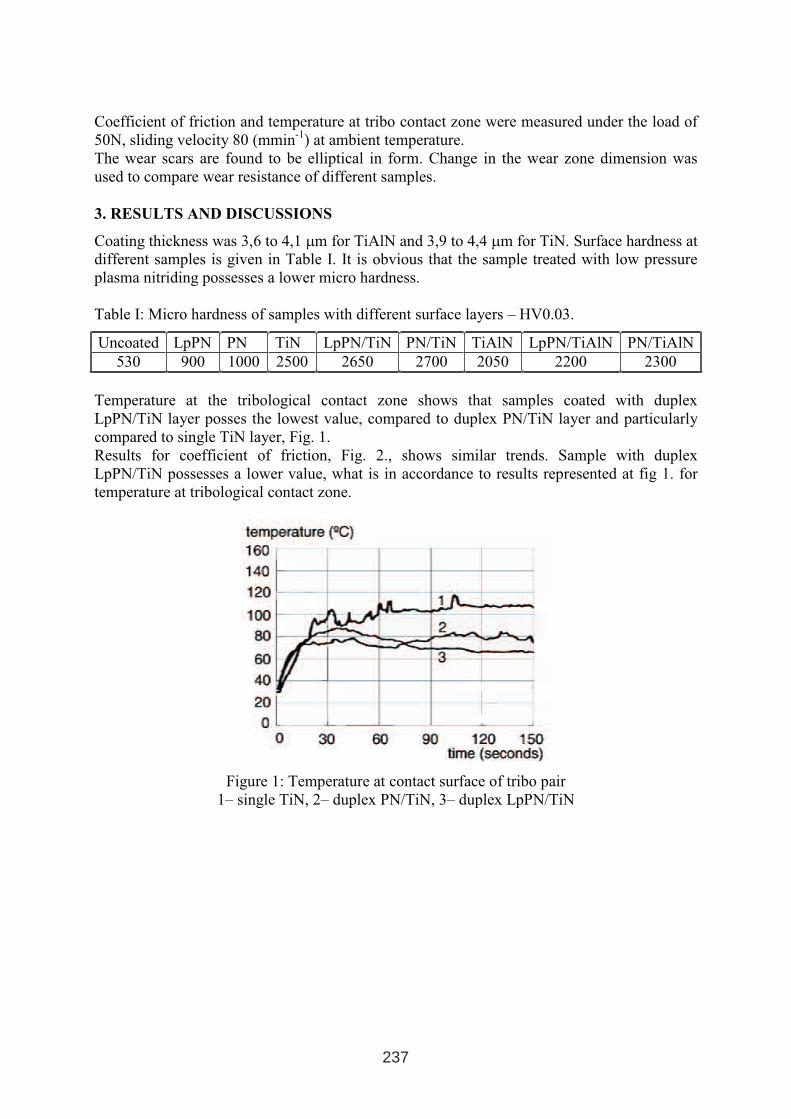
Coefficient of friction and temperature at tribo contact zone were measured under the load of
50N, sliding velocity 80 (mmin-1
) at ambient temperature.
The wear scars are found to be elliptical in form. Change in the wear zone dimension was
used to compare wear resistance of different samples.
3. RESULTS AND DISCUSSIONS
Coating thickness was 3,6 to 4,1 µm for TiAlN and 3,9 to 4,4 µm for TiN. Surface hardness at
different samples is given in Table I. It is obvious that the sample treated with low pressure
plasma nitriding possesses a lower micro hardness.
Table I: Micro hardness of samples with different surface layers – HV0.03.
Uncoated LpPN PN TiN LpPN/TiN PN/TiN TiAlN LpPN/TiAlN PN/TiAlN
530 900 1000 2500 2650 2700 2050 2200 2300
Temperature at the tribological contact zone shows that samples coated with duplex
LpPN/TiN layer posses the lowest value, compared to duplex PN/TiN layer and particularly
compared to single TiN layer, Fig. 1.
Results for coefficient of friction, Fig. 2., shows similar trends. Sample with duplex
LpPN/TiN possesses a lower value, what is in accordance to results represented at fig 1. for
temperature at tribological contact zone.
Figure 1: Temperature at contact surface of tribo pair
1– single TiN, 2– duplex PN/TiN, 3– duplex LpPN/TiN
237
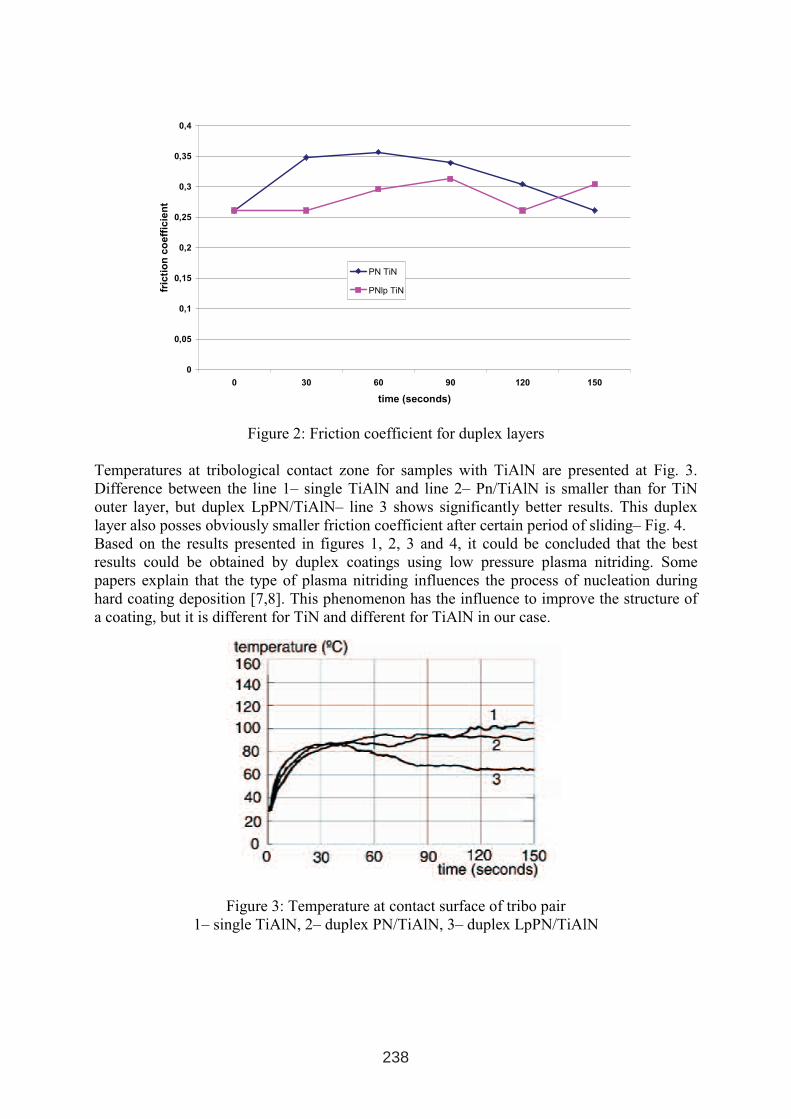
0
0,05
0,1
0,15
0,2
0,25
0,3
0,35
0,4
0 30 60 90 120 150
time (seconds)
fric
tio
nco
eff
icie
nt
PN TiN
PNlp TiN
Figure 2: Friction coefficient for duplex layers
Temperatures at tribological contact zone for samples with TiAlN are presented at Fig. 3.
Difference between the line 1– single TiAlN and line 2– Pn/TiAlN is smaller than for TiN
outer layer, but duplex LpPN/TiAlN– line 3 shows significantly better results. This duplex
layer also posses obviously smaller friction coefficient after certain period of sliding– Fig. 4.
Based on the results presented in figures 1, 2, 3 and 4, it could be concluded that the best
results could be obtained by duplex coatings using low pressure plasma nitriding. Some
papers explain that the type of plasma nitriding influences the process of nucleation during
hard coating deposition [7,8]. This phenomenon has the influence to improve the structure of
a coating, but it is different for TiN and different for TiAlN in our case.
Figure 3: Temperature at contact surface of tribo pair
1– single TiAlN, 2– duplex PN/TiAlN, 3– duplex LpPN/TiAlN
238

0
0,05
0,1
0,15
0,2
0,25
0,3
0,35
0,4
0 30 60 90 120 150
time (seconds)
fric
tio
nc
oe
ffic
ien
t
PN TiAlN
PNlp TiAlN
Figure 4: Friction coefficient for duplex TiAlN layers
Investigation with SEM shows typical structure for hard coatings, Fig 5. The films are very
dense. The interface indicates a very good coating to substrate adhesion. It was found that the
plasma-nitriding process enhanced the coating to substrates adhesion. In some places a
cohesive failure of the coating and the delimitation of the coating were observed.
Figure 5: Typical structure of TiN layer at duplex LpPN/TiN layer
239
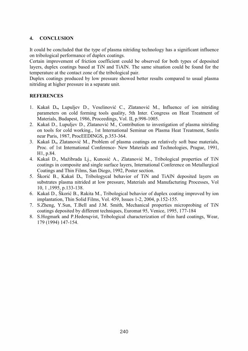
4. CONCLUSION
It could be concluded that the type of plasma nitriding technology has a significant influence
on tribological performance of duplex coatings.
Certain improvement of friction coefficient could be observed for both types of deposited
layers, duplex coatings based at TiN and TiAlN. The same situation could be found for the
temperature at the contact zone of the tribological pair.
Duplex coatings produced by low pressure showed better results compared to usual plasma
nitriding at higher pressure in a separate unit.
REFERENCES
1. Kakaš D., Lupuljev D., Veselinović C., Zlatanović M., Influence of ion nitriding
parameters on cold forming tools quality, 5th Inter. Congress on Heat Treatment of
Materials, Budapest, 1986, Proceedings, Vol. II, p.998-1005.
2. Kakaš D., Lupuljev D., Zlatanović M., Contribution to investigation of plasma nitriding
on tools for cold working., 1st International Seminar on Plasma Heat Treatment, Senlis
near Paris, 1987, ProcEEDINGS, p.353-364.
3. Kakaš D., Zlatanović M., Problem of plasma coatings on relatively soft base materials,
Proc. of 1st International Conference- New Materials and Technologies, Prague, 1991,
H1, p.84.
4. Kakaš D., Mažibrada Lj., Kunosić A., Zlatanović M., Tribological properties of TiN
coatings in composite and single surface layers, International Conference on Metallurgical
Coatings and Thin Films, San Diego, 1992, Poster section.
5. Škorić B., Kakaš D., Tribologycal behavior of TiN and TiAlN deposited layers on
substrates plasma nitrided at low pressure, Materials and Manufacturing Processes, Vol
10, 1 ,1995, p.133-138.
6. Kakaš D., Škorić B., Rakita M., Tribological behavior of duplex coating improved by ion
implantation, Thin Solid Films, Vol. 459, Issues 1-2, 2004, p.152-155.
7. S.Zheng, Y.Sun, T.Bell and J.M. Smith, Mechanical properties microprobing of TiN
coatings deposited by different techniques, Euromat 95, Venice, 1995, 177-184
8. S.Hogmark and P.Hedenqvist, Tribological characterization of thin hard coatings, Wear,
179 (1994) 147-154.
240
DIFFUSION CHROMIZED LAYERS PRODUCED ON
IRON AND STEEL SURFACE BY MEANS OF CVD
Ewa KASPRZYCKA, Bogdan BOGDAŃSKI
Institute of Precision Mechanics, Warsaw, Poland
ABSTRACT
Chemical vapour deposition of chromium on the surface of iron and low-carbon steel has
been investigated using a novel CVD method that combines the low cost of pack cementation
method with advantages of vacuum technique. Chromizing processes have been performed in
chromium chlorides atmosphere at a low-pressure range from 1 to 800 hPa, the treatment
temperature 800 to 950oC. The effect of the vacuum level during the process and the process
parameters such as time and temperature on the growth kinetics of diffusion layer on steel
surface has been investigated. The investigations have proved that the chromizing process
under low pressure, with static vacuum instead of dynamic vacuum conditions during the
holding is the most effective as far as the growth kinetics of diffusion layers is concerned.
Keywords: Thermochemical treatment, diffusion layer, chromizing, coating, diffusion
process
1. INTRODUCTION
Diffusion chromizing is a thermochemical treatment employed today for improving properties
of steel surface such as corrosion resistance and wear [1÷6]. Corrosion resistance is
characteristic of monophase layers of chromium in α–Fe solid solution structure. Chromized
layers of that structure can be obtained only on the pure iron and on special low-carbon steels
stabilized by means of strong carbide forming elements (Ti, Nb, V) binding the carbon in steel
as the stable carbides [1]. The diffusion chromizing by CVD consists in holding steel at the
temperature over 800oC in chromium compounds (e.g. chlorides) atmosphere. Chromium is
transferred to the steel surface by one or more of several possible deposition reaction (of
interchange, of reduction, or of thermal dissociation types) and then it diffuses in it to create a
layer. The process must be conducted in the absence of air to prevent oxidation of metallic
chromium which is the chromium source.
In this paper, a novel CVD method that combines the low cost of pack metallization and the
advantage of vacuum technique was investigated [7]. The coating process was based on the
formation of chromium chlorides atmosphere in situ during the processing. A metallic
chromium powder mixture with a halide activator (NH4Cl) was used as reagents.
The proposed method was obtained by means of heating a batch in a dynamic vacuum and
then holding it in a static vacuum [6, 7]. Usually, in vacuum techniques, the dynamic vacuum
is used, maintained by continuously working vacuum pumps which take away atmosphere
1 INTERNATIONAL CONFERENCE ON HEAT TREATMENT
AND SURFACE ENGINEERING OF TOOLS AND DIES
st
Pula, Croatia 08 - 11 June, 2005,
IFHTSE 2005
241
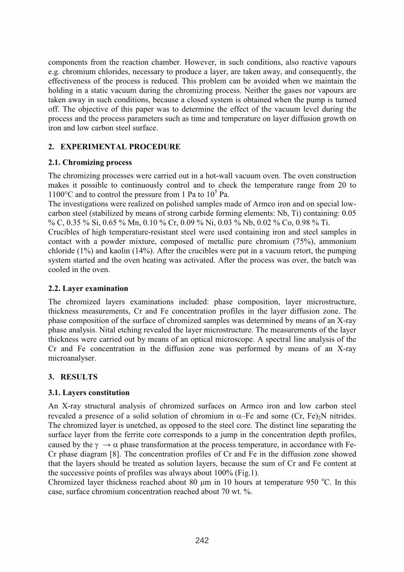
components from the reaction chamber. However, in such conditions, also reactive vapours
e.g. chromium chlorides, necessary to produce a layer, are taken away, and consequently, the
effectiveness of the process is reduced. This problem can be avoided when we maintain the
holding in a static vacuum during the chromizing process. Neither the gases nor vapours are
taken away in such conditions, because a closed system is obtained when the pump is turned
off. The objective of this paper was to determine the effect of the vacuum level during the
process and the process parameters such as time and temperature on layer diffusion growth on
iron and low carbon steel surface.
2. EXPERIMENTAL PROCEDURE
2.1. Chromizing process
The chromizing processes were carried out in a hot-wall vacuum oven. The oven construction
makes it possible to continuously control and to check the temperature range from 20 to
1100°C and to control the pressure from 1 Pa to 105
Pa.
The investigations were realized on polished samples made of Armco iron and on special low-
carbon steel (stabilized by means of strong carbide forming elements: Nb, Ti) containing: 0.05
% C, 0.35 % Si, 0.65 % Mn, 0.10 % Cr, 0.09 % Ni, 0.03 % Nb, 0.02 % Co, 0.98 % Ti.
Crucibles of high temperature-resistant steel were used containing iron and steel samples in
contact with a powder mixture, composed of metallic pure chromium (75%), ammonium
chloride (1%) and kaolin (14%). After the crucibles were put in a vacuum retort, the pumping
system started and the oven heating was activated. After the process was over, the batch was
cooled in the oven.
2.2. Layer examination
The chromized layers examinations included: phase composition, layer microstructure,
thickness measurements, Cr and Fe concentration profiles in the layer diffusion zone. The
phase composition of the surface of chromized samples was determined by means of an X-ray
phase analysis. Nital etching revealed the layer microstructure. The measurements of the layer
thickness were carried out by means of an optical microscope. A spectral line analysis of the
Cr and Fe concentration in the diffusion zone was performed by means of an X-ray
microanalyser.
3. RESULTS
3.1. Layers constitution
An X-ray structural analysis of chromized surfaces on Armco iron and low carbon steel
revealed a presence of a solid solution of chromium in α–Fe and some (Cr, Fe)2N nitrides.
The chromized layer is unetched, as opposed to the steel core. The distinct line separating the
surface layer from the ferrite core corresponds to a jump in the concentration depth profiles,
caused by the γ → α phase transformation at the process temperature, in accordance with Fe-
Cr phase diagram [8]. The concentration profiles of Cr and Fe in the diffusion zone showed
that the layers should be treated as solution layers, because the sum of Cr and Fe content at
the successive points of profiles was always about 100% (Fig.1).
Chromized layer thickness reached about 80 µm in 10 hours at temperature 950 oC. In this
case, surface chromium concentration reached about 70 wt. %.
242
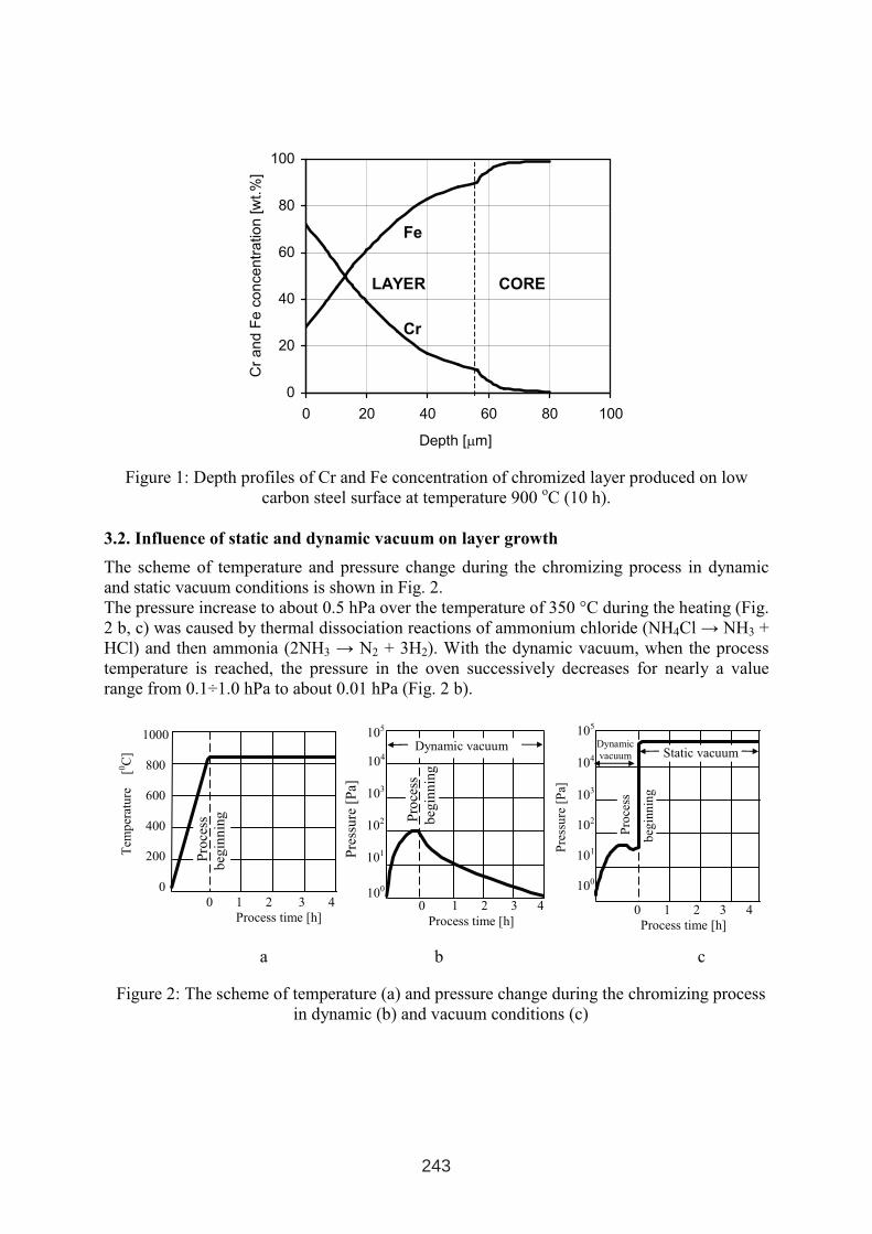
0
20
40
60
80
100
0 20 40 60 80 100
Depth [µm]
Cr
an
dF
eco
nce
ntr
atio
n[w
t.%
]
Fe
Cr
LAYER CORE
Figure 1: Depth profiles of Cr and Fe concentration of chromized layer produced on low
carbon steel surface at temperature 900 oC (10 h).
3.2. Influence of static and dynamic vacuum on layer growth
The scheme of temperature and pressure change during the chromizing process in dynamic
and static vacuum conditions is shown in Fig. 2.
The pressure increase to about 0.5 hPa over the temperature of 350 °C during the heating (Fig.
2 b, c) was caused by thermal dissociation reactions of ammonium chloride (NH4Cl → NH3 +
HCl) and then ammonia (2NH3 → N2 + 3H2). With the dynamic vacuum, when the process
temperature is reached, the pressure in the oven successively decreases for nearly a value
range from 0.1÷1.0 hPa to about 0.01 hPa (Fig. 2 b).
a b c
Figure 2: The scheme of temperature (a) and pressure change during the chromizing process
in dynamic (b) and vacuum conditions (c)
Pro
cess
beg
inn
ing
0 1 2 3 4
Process time [h]
Tem
per
atu
re[0
C]
1000
800
600
400
200
0
Dynamic
vacuum
105
104
103
102
101
100
0 1 2 3 4
Process time [h]
Pre
ssu
re[P
a]
Static vacuum
Pro
cess
beg
inn
ing
105
104
103
102
101
100
Pro
cess
beg
inn
ing
0 1 2 3 4
Process time [h]
Pre
ssu
re[P
a]
Dynamic vacuum
243
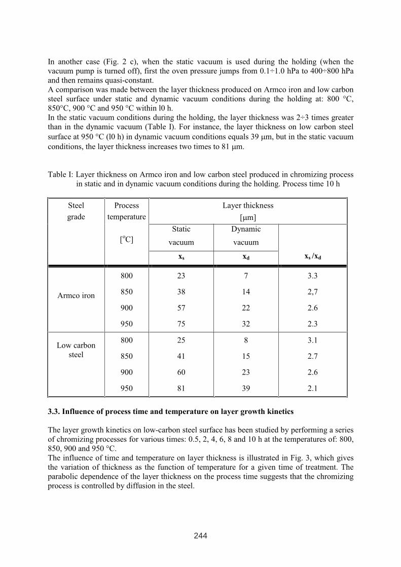
In another case (Fig. 2 c), when the static vacuum is used during the holding (when the
vacuum pump is turned off), first the oven pressure jumps from 0.1÷1.0 hPa to 400÷800 hPa
and then remains quasi-constant.
A comparison was made between the layer thickness produced on Armco iron and low carbon
steel surface under static and dynamic vacuum conditions during the holding at: 800 °C,
850°C, 900 °C and 950 °C within l0 h.
In the static vacuum conditions during the holding, the layer thickness was 2÷3 times greater
than in the dynamic vacuum (Table I). For instance, the layer thickness on low carbon steel
surface at 950 °C (l0 h) in dynamic vacuum conditions equals 39 µm, but in the static vacuum
conditions, the layer thickness increases two times to 81 µm.
Table I: Layer thickness on Armco iron and low carbon steel produced in chromizing process
in static and in dynamic vacuum conditions during the holding. Process time 10 h
Layer thickness
[µm]
Static
vacuum
Dynamic
vacuum
Steel
grade
Process
temperature
[oC]
xs xd xs /xd
Armco iron
800
850
900
950
23
38
57
75
7
14
22
32
3.3
2,7
2.6
2.3
Low carbon
steel
800
850
900
950
25
41
60
81
8
15
23
39
3.1
2.7
2.6
2.1
3.3. Influence of process time and temperature on layer growth kinetics
The layer growth kinetics on low-carbon steel surface has been studied by performing a series
of chromizing processes for various times: 0.5, 2, 4, 6, 8 and 10 h at the temperatures of: 800,
850, 900 and 950 °C.
The influence of time and temperature on layer thickness is illustrated in Fig. 3, which gives
the variation of thickness as the function of temperature for a given time of treatment. The
parabolic dependence of the layer thickness on the process time suggests that the chromizing
process is controlled by diffusion in the steel.
244
0
20
40
60
80
100
0 2 4 6 8 10
Process time [h]
La
ye
rth
ickn
ess
[ µm
]
950oC
900oC
850oC
800oC
Figure 3: Layer thickness of chromized low carbon steel as function of process time for
various temperatures
4. CONCLUSIONS
The investigations carried out in this research work have proved that the vacuum level kept
during the chromizing process as well as the process time and temperature influenced
significantly the growth of diffusion layers.
These diffusion layers produced on Armco-iron and on special low-carbon steel, containing
among others 0.98 % Ti, have a structure consisting of a solid solution chromium in α-Fe and
some (Cr, Fe)2N nitrides. Chromized layer thickness reached about 80 µm and surface
chromium concentration reached about 70 wt. % in 10 hours at temperature 950 oC.
It has been shown, that the chromizing process under low pressure, in static vacuum instead of
dynamic vacuum conditions during the holding, is more effective as far as the growth kinetics
of diffusion layers is concerned. Moreover, it has been proved that the kinetics of the
chromizing process is controlled by the diffusion of chromium in the steel.
REFERENCES
1. Dubinin G.N.: Diffusion Chromizing of Alloys, American Publ.Co., New Delhi (1987).
2. Sang Yul Lee, Gwang Seok Kim, Bum-Suk Kim: Surface and Coatings Technology, 177-
178(2004), p. 178-184.
3. Jyh-Wei Lee, Jenq-Gong Duh: Surface and Coatings Technology, 177(2004), p. 525-531.
4. Perez F. J., Hierro M. P., Carpintero M. C., Gomez C.: Surface and Coatings Technology,
184(2004), p. 47-54.
5. Kasprzycka E.: Problems of Engineering and Automation (Russia), 2(1999), p. 61-64.
6. Kasprzycka E.: Corrosion resistant layers produced from metals vapours (Cr, Ti) under
low pressure, Edited by Institute of Precision Mechanics, Warsaw (2002).
7. Kasprzycka, J. Tacikowski, and others, Polish Patent No 159 324, Warsaw (1993).
8. Massalski T. B.: Binary Alloy Phase Diagrams. Edition ASM, Metals Park, Ohio 1990.
245

DIFFUSION CHROMIZED LAYERS PRODUCED IN CHROMIUM
CHLORIDE ATMOSPHERE AT LOW PRESSURE
Ewa KASPRZYCKA, Bogdan BOGDAŃSKI
Institute of Precision Mechanics, Warsaw, Poland
ABSTRACT
Diffusion chromizing of tool steel, in chromium chloride atmosphere at low pressure, has
been investigated using a novel vacuum method that combines the low cost of pack powder
method with advantages of vacuum technique. A comparison was made between the layer
thickness produced on the tool steel surface using the novel vacuum method and a
conventional chromizing process by pack powder method. Chromizing processes have been
carried out in a hot-wall vacuum. The processes have been performed at a low pressure range
from 1 to 800 hPa, the treatment temperature 800 to 950oC. Studies of layer thickness, its
phase composition, Cr, Fe and C depth profiles in the diffusion zone of chromized layer have
been conducted. Chromizing conducted in chromium chloride atmosphere at low pressure, by
means a novel vacuum method, was found to be most effective for maximizing the rate
growth of diffusion layers than that for chromizing by pack cementation method.
Keywords: Thermochemical treatment, carbide layer, chromizing, coating, diffusion
process
1. INTRODUCTION
Diffusion chromizing is a thermochemical treatment employed today for improving properties
of steel surface such as wear and corrosion resistance [1÷7]. Carbon content plays an
important role in the diffusion chromizing of steels, since its diffusion to the surface (up hill
diffusion) during the process leads to its combination with chromium to form carbides. At
high carbon content in steels, the obtained diffusion layers are composed of chromium
carbides. Such layers are hard and wear resistant. Chromizing processes can be carried out by
pack [2÷7], salt bath [8], fluidized bad [9] and CVD (using chromium chloride compounds
[10]) methods. Industrial meaning has a powder pack method [2÷7]. The coating process
involves packing the steel in a powder mixture which contains a chromium source (pure
chromium or ferrochromium), inert filler (usually kaolin) and a halide activator (NH4Cl,
NH4J, ect). The diffusion chromizing consists in holding steel at the temperature over 900oC
in chromium compounds (e.g. chlorides) atmosphere. Chromium is transferred to the steel
surface by one or more of several possible deposition reaction (of interchange, of reduction,
or of thermal dissociation types) and then it diffuses in it to create a layer.
1 INTERNATIONAL CONFERENCE ON HEAT TREATMENT
AND SURFACE ENGINEERING OF TOOLS AND DIES
st
Pula, Croatia 08 - 11 June, 2005,
IFHTSE 2005
247
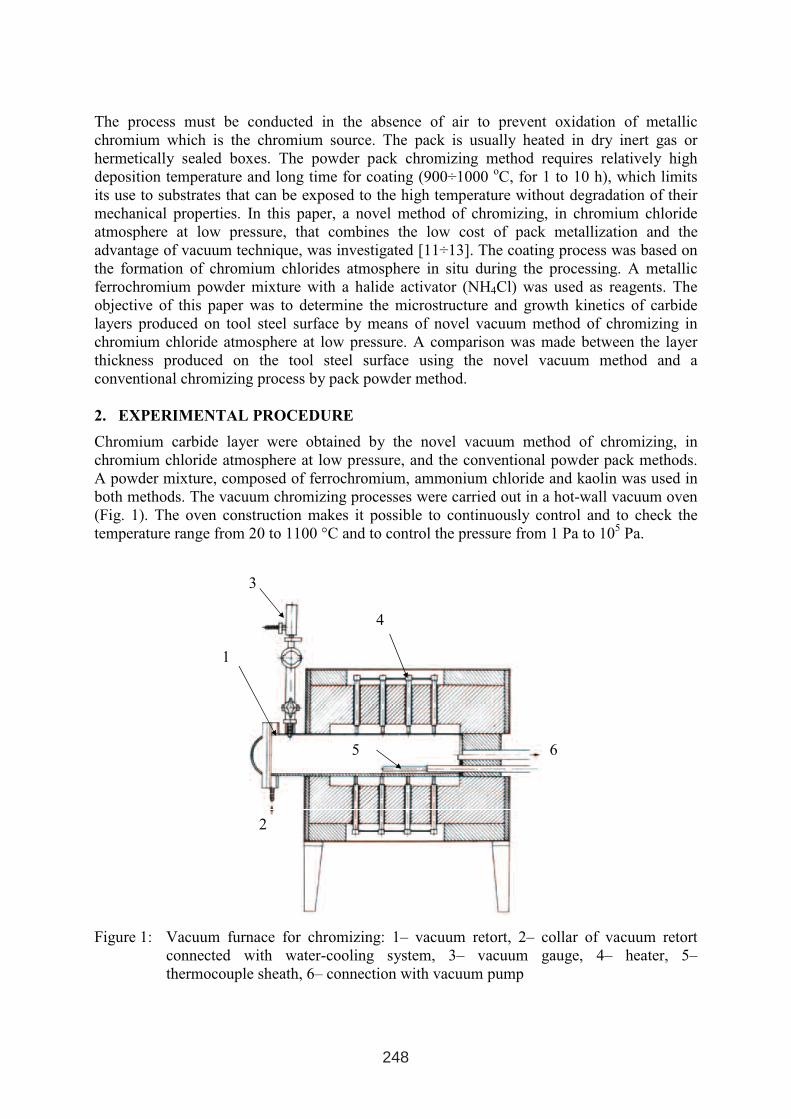
The process must be conducted in the absence of air to prevent oxidation of metallic
chromium which is the chromium source. The pack is usually heated in dry inert gas or
hermetically sealed boxes. The powder pack chromizing method requires relatively high
deposition temperature and long time for coating (900÷1000 oC, for 1 to 10 h), which limits
its use to substrates that can be exposed to the high temperature without degradation of their
mechanical properties. In this paper, a novel method of chromizing, in chromium chloride
atmosphere at low pressure, that combines the low cost of pack metallization and the
advantage of vacuum technique, was investigated [11÷13]. The coating process was based on
the formation of chromium chlorides atmosphere in situ during the processing. A metallic
ferrochromium powder mixture with a halide activator (NH4Cl) was used as reagents. The
objective of this paper was to determine the microstructure and growth kinetics of carbide
layers produced on tool steel surface by means of novel vacuum method of chromizing in
chromium chloride atmosphere at low pressure. A comparison was made between the layer
thickness produced on the tool steel surface using the novel vacuum method and a
conventional chromizing process by pack powder method.
2. EXPERIMENTAL PROCEDURE
Chromium carbide layer were obtained by the novel vacuum method of chromizing, in
chromium chloride atmosphere at low pressure, and the conventional powder pack methods.
A powder mixture, composed of ferrochromium, ammonium chloride and kaolin was used in
both methods. The vacuum chromizing processes were carried out in a hot-wall vacuum oven
(Fig. 1). The oven construction makes it possible to continuously control and to check the
temperature range from 20 to 1100 °C and to control the pressure from 1 Pa to 105
Pa.
Figure 1: Vacuum furnace for chromizing: 1– vacuum retort, 2– collar of vacuum retort
connected with water-cooling system, 3– vacuum gauge, 4– heater, 5–
thermocouple sheath, 6– connection with vacuum pump
6
1
3
5
2
4
248
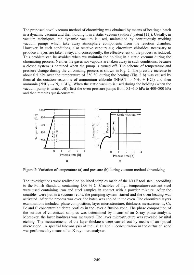
The proposed novel vacuum method of chromizing was obtained by means of heating a batch
in a dynamic vacuum and then holding it in a static vacuum (authors’ patent [11]). Usually, in
vacuum techniques, the dynamic vacuum is used, maintained by continuously working
vacuum pumps which take away atmosphere components from the reaction chamber.
However, in such conditions, also reactive vapours e.g. chromium chlorides, necessary to
produce a layer, are taken away, and consequently, the effectiveness of the process is reduced.
This problem can be avoided when we maintain the holding in a static vacuum during the
chromizing process. Neither the gases nor vapours are taken away in such conditions, because
a closed system is obtained when the pump is turned off. The scheme of temperature and
pressure change during the chromizing process is shown in Fig. 2. The pressure increase to
about 0.5 hPa over the temperature of 350 °C during the heating (Fig. 2 b) was caused by
thermal dissociation reactions of ammonium chloride (NH4Cl → NH3 + HCl) and then
ammonia (2NH3 → N2 + 3H2). When the static vacuum is used during the holding (when the
vacuum pump is turned off), first the oven pressure jumps from 0.1÷1.0 hPa to 400÷800 hPa
and then remains quasi-constant.
a b
Figure 2: Variation of temperature (a) and pressure (b) during vacuum method chromizing
The investigations were realized on polished samples made of the N11E tool steel, according
to the Polish Standard, containing 1,06 % C. Crucibles of high temperature-resistant steel
were used containing iron and steel samples in contact with a powder mixture. After the
crucibles were put in a vacuum retort, the pumping system started and the oven heating was
activated. After the process was over, the batch was cooled in the oven. The chromized layers
examinations included: phase composition, layer microstructure, thickness measurements, Cr,
Fe and C concentration depth profiles in the layer diffusion zone. The phase composition of
the surface of chromized samples was determined by means of an X-ray phase analysis.
Moreover, the layer hardness was measured. The layer microstructure was revealed by nital
etching. The measurements of the layer thickness were carried out by means of an optical
microscope. A spectral line analysis of the Cr, Fe and C concentration in the diffusion zone
was performed by means of an X-ray microanalyser.
1000
800
600
400
200
0
Pro
cess
beg
inn
ing
0 1 2 3 4
Process time [h]
Tem
per
atu
re[0
C]
105
104
103
102
101
100
0 1 2 3 4
Process time [h]
Pre
ssu
re[P
a]
Static vacuum
Pro
cess
beg
inn
ing
249
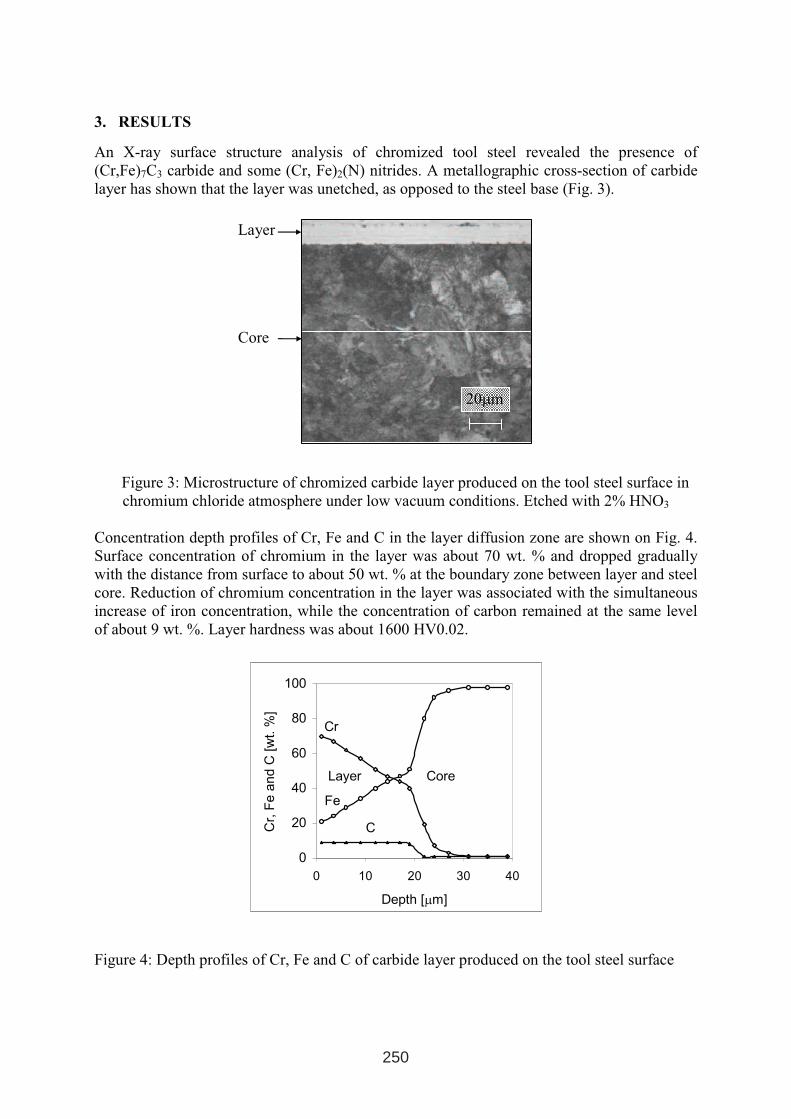
0
20
40
60
80
100
0 10 20 30 40
Depth [µm]
Cr,
Fe
an
dC
[wt.
%]
Cr
Fe
C
Layer Core
3. RESULTS
An X-ray surface structure analysis of chromized tool steel revealed the presence of
(Cr,Fe)7C3 carbide and some (Cr, Fe)2(N) nitrides. A metallographic cross-section of carbide
layer has shown that the layer was unetched, as opposed to the steel base (Fig. 3).
Figure 3: Microstructure of chromized carbide layer produced on the tool steel surface in
chromium chloride atmosphere under low vacuum conditions. Etched with 2% HNO3
Concentration depth profiles of Cr, Fe and C in the layer diffusion zone are shown on Fig. 4.
Surface concentration of chromium in the layer was about 70 wt. % and dropped gradually
with the distance from surface to about 50 wt. % at the boundary zone between layer and steel
core. Reduction of chromium concentration in the layer was associated with the simultaneous
increase of iron concentration, while the concentration of carbon remained at the same level
of about 9 wt. %. Layer hardness was about 1600 HV0.02.
Figure 4: Depth profiles of Cr, Fe and C of carbide layer produced on the tool steel surface
Layer
Core
20µm
250
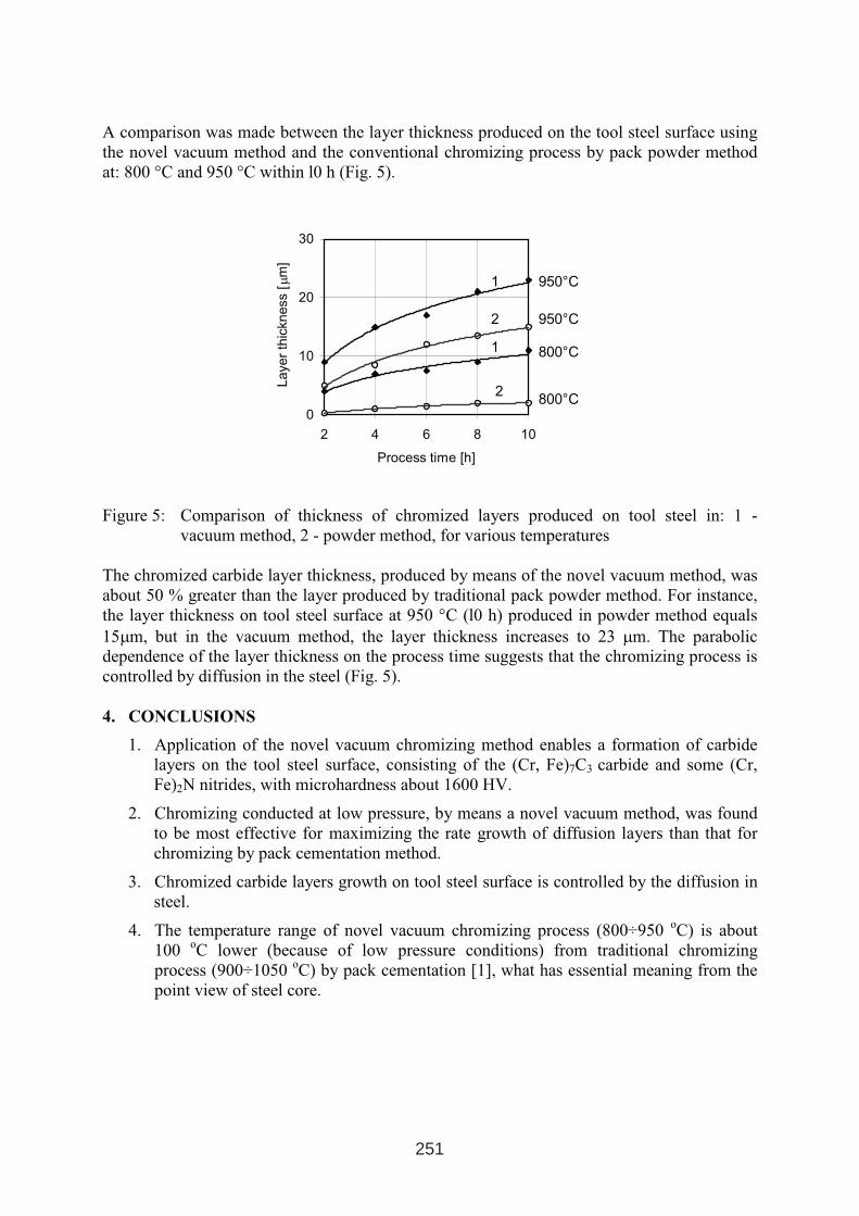
A comparison was made between the layer thickness produced on the tool steel surface using
the novel vacuum method and the conventional chromizing process by pack powder method
at: 800 °C and 950 °C within l0 h (Fig. 5).
0
10
20
30
2 4 6 8 10
Process time [h]
Layer
thic
kness
[ µm
]950°C
950°C
800°C
800°C
1
1
2
2
Figure 5: Comparison of thickness of chromized layers produced on tool steel in: 1 -
vacuum method, 2 - powder method, for various temperatures
The chromized carbide layer thickness, produced by means of the novel vacuum method, was
about 50 % greater than the layer produced by traditional pack powder method. For instance,
the layer thickness on tool steel surface at 950 °C (l0 h) produced in powder method equals
15µm, but in the vacuum method, the layer thickness increases to 23 µm. The parabolic
dependence of the layer thickness on the process time suggests that the chromizing process is
controlled by diffusion in the steel (Fig. 5).
4. CONCLUSIONS
1. Application of the novel vacuum chromizing method enables a formation of carbide
layers on the tool steel surface, consisting of the (Cr, Fe)7C3 carbide and some (Cr,
Fe)2N nitrides, with microhardness about 1600 HV.
2. Chromizing conducted at low pressure, by means a novel vacuum method, was found
to be most effective for maximizing the rate growth of diffusion layers than that for
chromizing by pack cementation method.
3. Chromized carbide layers growth on tool steel surface is controlled by the diffusion in
steel.
4. The temperature range of novel vacuum chromizing process (800÷950 oC) is about
100oC lower (because of low pressure conditions) from traditional chromizing
process (900÷1050 oC) by pack cementation [1], what has essential meaning from the
point view of steel core.
251
REFERENCES
1. Dubinin G.N.: Diffusion Chromizing of Alloys, American Publ.Co., New Delhi (1987).
2. Meier G. H., Cheng C., Perkins R. A., Bakker W.: Diffusion chromizing of ferrous
alloys. Surface and Coatings Technology, vol. 39-40, nr 1-3, 1989, p. 53÷64.
3. Liu C. T., Wu J. D.: The structure and high temperature corrosion properties of
chromized coatings. . Surface and Coatings Technology, vol. 43-44, nr 1-3, 1990, p.
493÷499.
4. Bianco R., Rapp R. A., Jacobson N. S.: Volatile species in halide-activated diffusion
coating packs. Oxidation of Metals, vol. 38, nr 1-2, 1992, p. 33÷43.
5. Harper M. A., Rapp R. A.: Codeposited chromium and silicon diffusion coatings for
iron-base alloys via pack cementation. Oxidation of Metals, vol. 42, nr 3-4, 1994, p.
303÷333.
6. Sang Yul Lee, Gwang Seok Kim, Bum- Suk Kim: Mechanical properties of duplex
layer formed on AISI 403 stainless steel by chromizing and boronizing treatment.
Surface and Coatings Technology 177-178 (2004), p.178÷184.
7. Jyh-Wei Lee, Jenq-Gong Duh: Evaluation of microstructure and mechanical properties
of chromized steels with different carbon contents. Surface and Coatings Technology
177 (2004), p. 525-531.
8. Reynoldson R. W.: Advances in surface treatments using fluidised beds. Surface and
Coatings Technology, vol. 71, 1995, p. 102÷107.
9. Perez F. J., Hierro M. P., Carpintero M. C., Gomez C.: Chromising of stainless steels by
the use of CVD-FBR technology. Surface and Coatings Technology 184 (2004), p.47-54.
10. Jyrkäs K.: Diffusion chromising of steel by CVD using chloride compounds: 4.
Influence of steel composition. Surface Engineering, vol. 7, nr 3, 1991, p. 239÷249.
11. Kasprzycka, J. Tacikowski, and others, Polish Patent No 159 324, Warsaw (1993).
12. Kasprzycka E.: Problems of Engineering and Automation (Russia) 2 (1999), p. 61-64.
13. Kasprzycka E.: Corrosion resistant layers produced from metals vapors (Cr, Ti) under
low pressure, Edited by Institute of Precision Mechanics, Warsaw (2002).
252
ANTICARBURISING COATINGS
APPLIED ON PARTS OF CARBURISING FURNACES
M. Garbiak, B. Piekarski
Szczecin University of Technology, 70-310 Szczecin, Al. Piastów 17, Poland, [email protected]
ABSTRACT
This paper shows the results of research on application of aluminium-based coatings to protect
castings made from cast steel type 36 %Ni-18 %Cr, operating under the conditions of thermal
shocks, from an adverse effect of the carburising atmosphere. The coatings were produced by
two methods: the powder method and the paste method. It has been proved that the examined
coatings can provide a temporary protection against carburising effect to cast parts of the
carburising furnaces.
Keywords: Fe-Ni-Cr cast steel, protective coatings, resistance against carburisation
1. INTRODUCTION
The creep-resistant parts (CRPs) of carburising furnaces like grates, fixtures, fans, radiant
heating tubes, etc. are made from nickel-chromium cast steel. During operation they suffer
wear and tear caused mainly by the effect of carburising process and thermal fatigue (Fig. 1).
A retardation of the processes which result in destruction of castings is achieved through
application of modern materials and advanced design [1, 2]. In former case, the life of CRPs
can be made longer by application onto their surface of an anticarburising coating, e.g. based
on aluminium [3]. The task of the coating is to prevent the casting from getting carburised
under the conditions of thermal shocks.
1 INTERNATIONAL CONFERENCE ON HEAT TREATMENT
AND SURFACE ENGINEERING OF TOOLS AND DIES
st
Pula, Croatia 08 - 11 June, 2005,
IFHTSE 2005
253
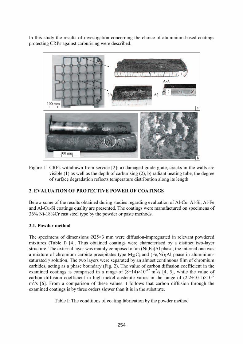
In this study the results of investigation concerning the choice of aluminium-based coatings
protecting CRPs against carburising were described.
a
100 mm
b
100 mm
A-A
A A
1
2
Figure 1: CRPs withdrawn from service [2]: a) damaged guide grate, cracks in the walls are
visible (1) as well as the depth of carburising (2), b) radiant heating tube, the degree
of surface degradation reflects temperature distribution along its length
2. EVALUATION OF PROTECTIVE POWER OF COATINGS
Below some of the results obtained during studies regarding evaluation of Al-Cu, Al-Si, Al-Fe
and Al-Cu-Si coatings quality are presented. The coatings were manufactured on specimens of
36% Ni-18%Cr cast steel type by the powder or paste methods.
2.1. Powder method
The specimens of dimensions Ø25×3 mm were diffusion-impregnated in relevant powdered
mixtures (Table I) [4]. Thus obtained coatings were characterised by a distinct two-layer
structure. The external layer was mainly composed of an (Ni,Fe)Al phase; the internal one was
a mixture of chromium carbide precipitates type M23C6 and (Fe,Ni)3Al phase in aluminium-
saturated γ solution. The two layers were separated by an almost continuous film of chromium
carbides, acting as a phase boundary (Fig. 2). The value of carbon diffusion coefficient in the
examined coatings is comprised in a range of (8÷14)×10-12
m2/s [4, 5], while the value of
carbon diffusion coefficient in high-nickel austenite varies in the range of (2.2÷10.1)×10-9
m2/s [6]. From a comparison of these values it follows that carbon diffusion through the
examined coatings is by three orders slower than it is in the substrate.
Table I: The conditions of coating fabrication by the powder method
254
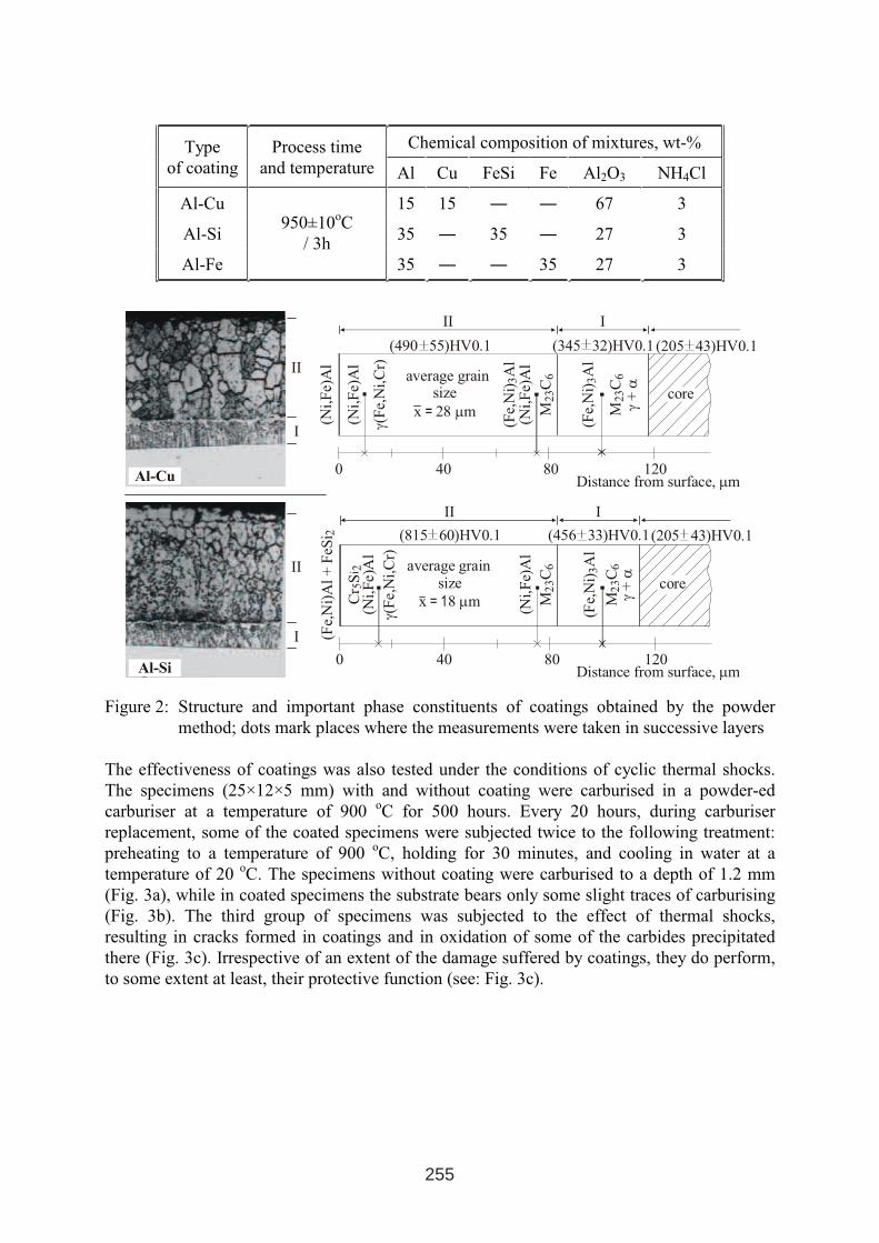
Chemical composition of mixtures, wt-%Type
of coating
Process time
and temperature Al Cu FeSi Fe Al2O3 NH4Cl
Al-Cu 15 15 ― ― 67 3
Al-Si 35 ― 35 ― 27 3
Al-Fe
950±10oC
/ 3h
35 ― ― 35 27 3
0 40 80 120
(Ni,
Fe)
Al
(Ni,
Fe)
Al
(Fe,
Ni)
Al
3
(Fe,
Ni)
Al
3
MC
23
6
MC
23
6
γ(F
e,N
i,C
r)
γα
+
(490 55)HV0.1 (345 32)HV0.1
average grainsize
x 28 m = µ
III
I
II
core
(Ni,
Fe)
Al
0 40 80 120Distance from surface, mµ
(Ni,
Fe)
Al
(Ni,
Fe)A
l
(Fe,
Ni)
Al
3
MC
23
6
MC
23
6
γ(F
e,N
i,C
r)
γα
+
(815 60)HV0.1 (456 33)HV0.1
average grainsize
x 8 m = 1 µ
III
I
II
(Fe,
Ni)
Al
+F
eSi 2
Cr
S5
i 2
Al-Si
Al-Cu
core
Distance from surface, mµ
(205 43)HV0.1
(205 43)HV0.1
Figure 2: Structure and important phase constituents of coatings obtained by the powder
method; dots mark places where the measurements were taken in successive layers
The effectiveness of coatings was also tested under the conditions of cyclic thermal shocks.
The specimens (25×12×5 mm) with and without coating were carburised in a powder-ed
carburiser at a temperature of 900oC for 500 hours. Every 20 hours, during carburiser
replacement, some of the coated specimens were subjected twice to the following treatment:
preheating to a temperature of 900oC, holding for 30 minutes, and cooling in water at a
temperature of 20oC. The specimens without coating were carburised to a depth of 1.2 mm
(Fig. 3a), while in coated specimens the substrate bears only some slight traces of carburising
(Fig. 3b). The third group of specimens was subjected to the effect of thermal shocks,
resulting in cracks formed in coatings and in oxidation of some of the carbides precipitated
there (Fig. 3c). Irrespective of an extent of the damage suffered by coatings, they do perform,
to some extent at least, their protective function (see: Fig. 3c).
255
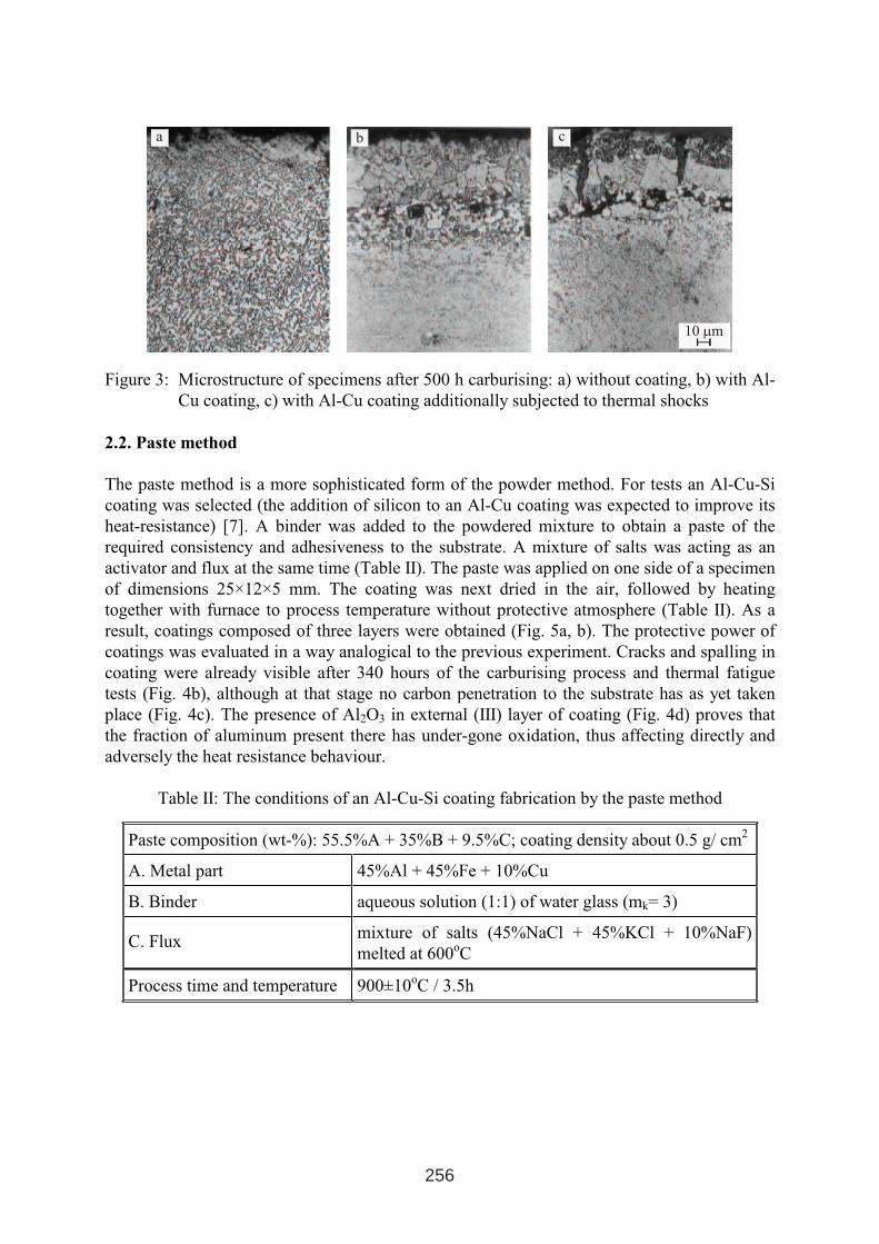
a b c
10 mµ
Figure 3: Microstructure of specimens after 500 h carburising: a) without coating, b) with Al-
Cu coating, c) with Al-Cu coating additionally subjected to thermal shocks
2.2. Paste method
The paste method is a more sophisticated form of the powder method. For tests an Al-Cu-Si
coating was selected (the addition of silicon to an Al-Cu coating was expected to improve its
heat-resistance) [7]. A binder was added to the powdered mixture to obtain a paste of the
required consistency and adhesiveness to the substrate. A mixture of salts was acting as an
activator and flux at the same time (Table II). The paste was applied on one side of a specimen
of dimensions 25×12×5 mm. The coating was next dried in the air, followed by heating
together with furnace to process temperature without protective atmosphere (Table II). As a
result, coatings composed of three layers were obtained (Fig. 5a, b). The protective power of
coatings was evaluated in a way analogical to the previous experiment. Cracks and spalling in
coating were already visible after 340 hours of the carburising process and thermal fatigue
tests (Fig. 4b), although at that stage no carbon penetration to the substrate has as yet taken
place (Fig. 4c). The presence of Al2O3 in external (III) layer of coating (Fig. 4d) proves that
the fraction of aluminum present there has under-gone oxidation, thus affecting directly and
adversely the heat resistance behaviour.
Table II: The conditions of an Al-Cu-Si coating fabrication by the paste method
Paste composition (wt-%): 55.5%A + 35%B + 9.5%C; coating density about 0.5 g/ cm2
A. Metal part 45%Al + 45%Fe + 10%Cu
B. Binder aqueous solution (1:1) of water glass (mk= 3)
C. Fluxmixture of salts (45%NaCl + 45%KCl + 10%NaF)
melted at 600oC
Process time and temperature 900±10oC / 3.5h
256
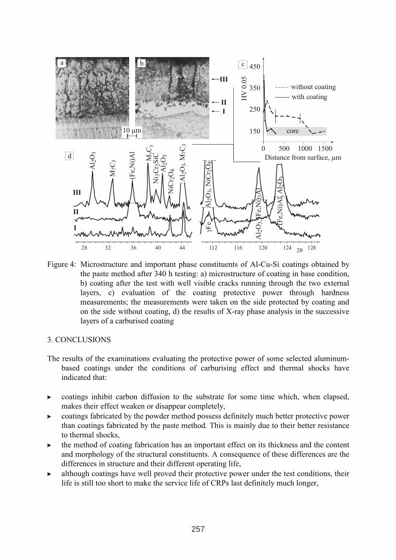
a
I
II
III
28 44403632 128124120116112
(Fe,
Ni)
Al,
Al
O2
3
Al
O(F
e,N
i)A
l2
3,
3
γFe
Al
O,N
iCr
O2
32
4
Al
OM
C2
3,
73
NiC
rO
24A
lO
23
MC
73
(Fe,
Ni)
Al
MC
73
2θ
Ni
Cr
SiC
32
0 500 15001000
Distance from surface, mµ
with coating
without coating
core
HV
0.0
5
150
250
350
450
III
II
I
d
c
Al
O2
3
b
10 mµ
Figure 4: Microstructure and important phase constituents of Al-Cu-Si coatings obtained by
the paste method after 340 h testing: a) microstructure of coating in base condition,
b) coating after the test with well visible cracks running through the two external
layers, c) evaluation of the coating protective power through hardness
measurements; the measurements were taken on the side protected by coating and
on the side without coating, d) the results of X-ray phase analysis in the successive
layers of a carburised coating
3. CONCLUSIONS
The results of the examinations evaluating the protective power of some selected aluminum-
based coatings under the conditions of carburising effect and thermal shocks have
indicated that:
� coatings inhibit carbon diffusion to the substrate for some time which, when elapsed,
makes their effect weaken or disappear completely,
� coatings fabricated by the powder method possess definitely much better protective power
than coatings fabricated by the paste method. This is mainly due to their better resistance
to thermal shocks,
� the method of coating fabrication has an important effect on its thickness and the content
and morphology of the structural constituents. A consequence of these differences are the
differences in structure and their different operating life,
� although coatings have well proved their protective power under the test conditions, their
life is still too short to make the service life of CRPs last definitely much longer,
257
� in view of a good resistance to carburising effects, further studies on how to make the
coatings life last longer are well justified, specially for those CRPs which are operating
within a relatively stable field of temperatures (radiant heating tubes, fans).
REFERENCES
1. Steinkusch W.: Gas Wärme Inter., 6(1987)340.
2. Hocking M. G., Vasantasree V., Sidky P. S.: Metallic and ceramic coatings, Longman
Scientic & Technical, UK 1989.
3. Piekarski B.: Austenitic steel castings used in construction of carburising furnaces–
theoretical and practical aspects of increasing operating life (in Polish). Zesz. Nauk. Ploit.
Szczecińskiej, No 573, Szczecin 2003.
4. Christodulu P., B. Piekarski B.: Neue Hütte, 5(1986)192.
5. Kubicki J., Piekarski B.: Inż. Mat., 4(1998)1104.
6. Bose S. K., Grabke H. J.: Z. Metalikde., 1(1976)8.
7. Garbiak M. et al: Przeg. Odlew., 9(2004)742.
258
NANO TECHNOLOGY FOR SURFACE TREATMENT OF
FERROMAGNETIC MATERIALS
A. Makedonski*, B. Makedonski *, S. Troha**
* Technical University of Sofia, Bulgaria; Faculty of Machine Technology
e-mail: [email protected]
∗∗University of Rijeka, Croatia; Faculty of Engineering
e-mail: [email protected]
ABSTRACT
In the present work are to be considered the possibilities of electro-physical method for action
of surface structural of ferromagnetic materials (cutting tools and parts). Said electro-physical
action (magnetic and ultrasound) proceeding by a complex mechanism when applied thereto.
The input energy being delivered to the work-materials causing an increase of the strength
thereof, said increase of the strength resulting from both impurity defects motion and
dislocations being induced thereto, said induced motions leading to (crystal) lattice
transformation and a new structure configuration formation thereof. Said combined method
provides advantages consisting of a short-duration action time and low energy-intensity than
hitherto.
Key words: CEPT, PMF & US, CMF & US, devices
1. INTRODUCTION
The improvement of the wear resistance of both cutting tools and important machine-building
parts is a live task and its solution is searched in all sectors of the industry [1]. From the
existing variety of technologies pursuing as an ultimate goal the solution of the above said
task, presently none conventional technologies and especially the electrical-physical methods
of treatment (e.g. magnetic, ultrasound, electrical-discharge, laser, combined types thereof,
etc.) are of particular interest. As a rule, with the combined electrical-physical treatment
methods (i.e. which are putting in the treatment zone more than one kind of energy) the
process effectiveness is intensified considerably. The latter is confirmed by the created and
1 INTERNATIONAL CONFERENCE ON HEAT TREATMENT
AND SURFACE ENGINEERING OF TOOLS AND DIES
st
Pula, Croatia 08 - 11 June, 2005,
IFHTSE 2005
259
protected con international patent method for combined (multi-process) electrical-physical
treatment (or CEPT) [2]. Its essence consists of the treated tool/part placement under a
magnetic field featuring preliminary set parameters thereof, said tool/part being
simultaneously exposed to mechanical vibrations in direction parallel to the direction of the
applied said magnetic field, said mechanical vibrations having frequency of the ultrasonic
wave range. One of the advantages of the CEPT method is its possibility to exercise influence
on the service characteristics of the ferromagnetic materials without any change in the shape
and dimensions thereof, and under minimal consumption of both time and input energy. The
keeping of the initial shape and the dimensions is of a particular importance for both sizing
and profile cutters used in the method of copying and parts made with high accuracy. It is
well known that the application of all of the remaining methods- aiming an increase of the
durability (under wear) of tools/parts- results in deviations of the initial dimensions thereof
(e.g. coatings, Electro-erosion, etc.). Secondly, the semi-industrial and industrial devices
being made up to the moment for the implementation of said CEPT-method -i.e. "MAGNIT-
ULTRAZVUK", "ULTRAMIT", "MUZ-1" and "MUZ-2"- are low power intensive and do
not demand special premises.
Thirdly, the CEPT-method is carried out under room temperature, its impact is of short
duration (from some seconds to few minutes) but the effect thereof being expressed in several
times increase of the durability (under wear) of the treated tools/parts.
In the fourth place, with both development and perfection of the device's generations '"MUZ-
1M" and "MUZ-2" the range of tools being treated was significantly expanded to include such
items as circular saws, gear cutters, hob cutters, band-saw blades, hack-saws, etc.
Thus, all this define the main directions of the application of the CEPT-method, namely:
- as a technological stage in the cutting tools production, or as a process which follows
the tools' regrinding,
- as a method for strengthening the surface treatment of the parts made of ferromagnetic
materials, against the latter being presented high service requirements.
Besides the perfection of the design of the devices developed, the nature of the impacts
applied was studied [3-7]. Under optimization are the magnetic field intensity and duration of
the combined impact and both principal schemes and designs of the magnetic coil , thus
receiving an optimum of the effect of the treatment applied.
260
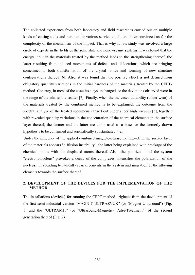
The collected experience from both laboratory and field researches carried out on multiple
kinds of cutting tools and parts under various service conditions have convinced us for the
complexity of the mechanism of the impact. That is why for its study was involved a large
circle of experts in the fields of the solid state and none organic systems. It was found that the
energy input in the materials treated by the method leads to the strengthening thereof, the
latter resulting from induced movements of defects and dislocations, which are bringing
sometimes to both transformation of the crystal lattice and forming of new structure
configurations thereof [6]. Also, it was found that the positive effect is not defined from
obligatory quantity variations in the initial hardness of the materials treated by the CEPT-
method. Contrary, in most of the cases its stays unchanged, or the deviations observed were in
the range of the admissible scatter [7]. Finally, when the increased durability (under wear) of
the materials treated by the combined method is to be explained, the outcome from the
spectral analyze of the treated specimens carried out under super high vacuum [3], together
with revealed quantity variations in the concentration of the chemical elements in the surface
layer thereof, the former and the latter are to be used as a base for the formerly drawn
hypothesis to be confirmed and scientifically substantiated, i.e.:
Under the influence of the applied combined magneto-ultrasound impact, in the surface layer
of the materials appears "diffusion instability", the latter being explained with breakage of the
chemical bonds with the displaced atoms thereof. Also, the polarization of the system
"electrons-nucleus" provokes a decay of the complexes, intensifies the polarization of the
nucleus, thus leading to radically rearrangements in the system and migration of the alloying
elements towards the surface thereof.
2. DEVELOPMENT OF THE DEVICES FOR THE IMPLEMENTATION OF THE
METHOD
The installations (devices) for running the CEPT-method originate from the development of
the first semi-industrial version "MAGNIT-ULTRAZVUK" (or "Magnet-Ultrasound") (Fig.
1) and the "ULTRAMIT" (or "Ultrasound-Magnetic- Pulse-Treatment") of the second
generation thereof (Fig. 2).
261
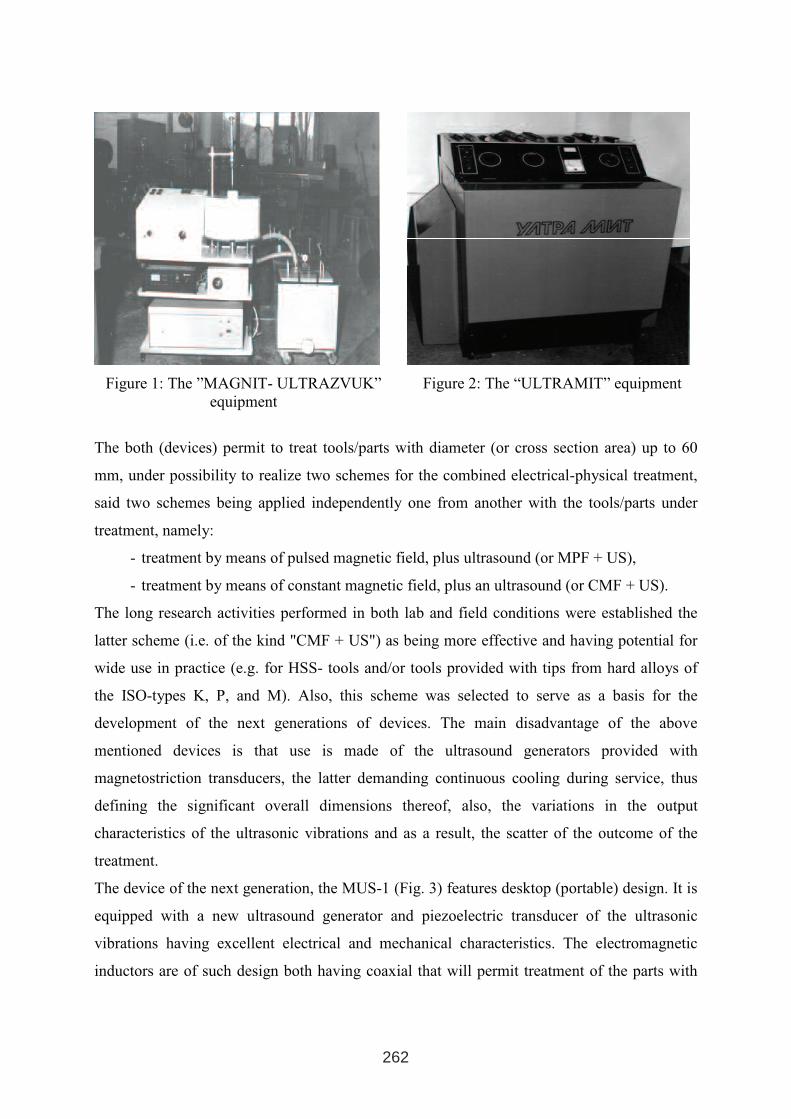
Figure 1: The ”MAGNIT- ULTRAZVUK”
equipment
Figure 2: The “ULTRAMIT” equipment
The both (devices) permit to treat tools/parts with diameter (or cross section area) up to 60
mm, under possibility to realize two schemes for the combined electrical-physical treatment,
said two schemes being applied independently one from another with the tools/parts under
treatment, namely:
- treatment by means of pulsed magnetic field, plus ultrasound (or MPF + US),
- treatment by means of constant magnetic field, plus an ultrasound (or CMF + US).
The long research activities performed in both lab and field conditions were established the
latter scheme (i.e. of the kind "CMF + US") as being more effective and having potential for
wide use in practice (e.g. for HSS- tools and/or tools provided with tips from hard alloys of
the ISO-types K, P, and M). Also, this scheme was selected to serve as a basis for the
development of the next generations of devices. The main disadvantage of the above
mentioned devices is that use is made of the ultrasound generators provided with
magnetostriction transducers, the latter demanding continuous cooling during service, thus
defining the significant overall dimensions thereof, also, the variations in the output
characteristics of the ultrasonic vibrations and as a result, the scatter of the outcome of the
treatment.
The device of the next generation, the MUS-1 (Fig. 3) features desktop (portable) design. It is
equipped with a new ultrasound generator and piezoelectric transducer of the ultrasonic
vibrations having excellent electrical and mechanical characteristics. The electromagnetic
inductors are of such design both having coaxial that will permit treatment of the parts with
262
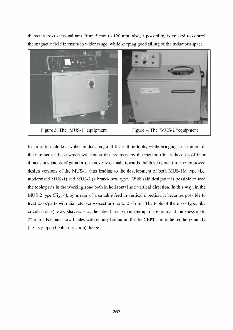
diameter/cross sectional area from 5 mm to 120 mm, also, a possibility is created to control
the magnetic field intensity in wider range, while keeping good filling of the inductor's space.
Figure 3: The "MUS-1" equipment Figure 4. The “MUS-2 “equipment
In order to include a wider product range of the cutting tools, while bringing to a minimum
the number of those which will hinder the treatment by the method (this is because of their
dimensions and configuration), a move was made towards the development of the improved
design versions of the MUS-1, thus leading to the development of both MUS-1M type (i.e.
modernized MUS-1) and MUS-2 (a brand- new type). With said designs it is possible to feed
the tools/parts in the working zone both in horizontal and vertical direction. In this way, in the
MUS-2 type (Fig. 4), by means of a suitable feed in vertical direction, it becomes possible to
treat tools/parts with diameter (cross-section) up to 210 mm. The tools of the disk- type, like
circular (disk) saws, shavers, etc., the latter having diameter up to 350 mm and thickness up to
22 mm, also, band-saw blades without any limitation for the CEPT, are to be fed horizontally
(i.e. in perpendicular direction) thereof.
263
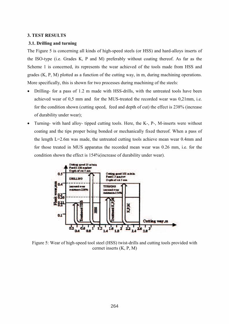
3. TEST RESULTS
3.1. Drilling and turning
The Figure 5 is concerning all kinds of high-speed steels (or HSS) and hard-alloys inserts of
the ISO-type (i.e. Grades K, P and M) preferably without coating thereof. As far as the
Scheme 1 is concerned, its represents the wear achieved of the tools made from HSS and
grades (K, P, M) plotted as a function of the cutting way, in m, during machining operations.
More specifically, this is shown for two processes during machining of the steels:
• Drilling- for a pass of 1.2 m made with HSS-drills, with the untreated tools have been
achieved wear of 0,5 mm and for the MUS-treated the recorded wear was 0,21mm, i.e.
for the condition shown (cutting speed, feed and depth of cut) the effect is 238% (increase
of durability under wear);
• Turning- with hard alloy- tipped cutting tools. Here, the K-, P-, M-inserts were without
coating and the tips proper being bonded or mechanically fixed thereof. When a pass of
the length L=2.6m was made, the untreated cutting tools achieve mean wear 0.4mm and
for those treated in MUS apparatus the recorded mean wear was 0.26 mm, i.e. for the
condition shown the effect is 154%(increase of durability under wear).
Figure 5: Wear of high-speed tool steel (HSS) twist-drills and cutting tools provided with
cermet inserts (K, P, M)
264
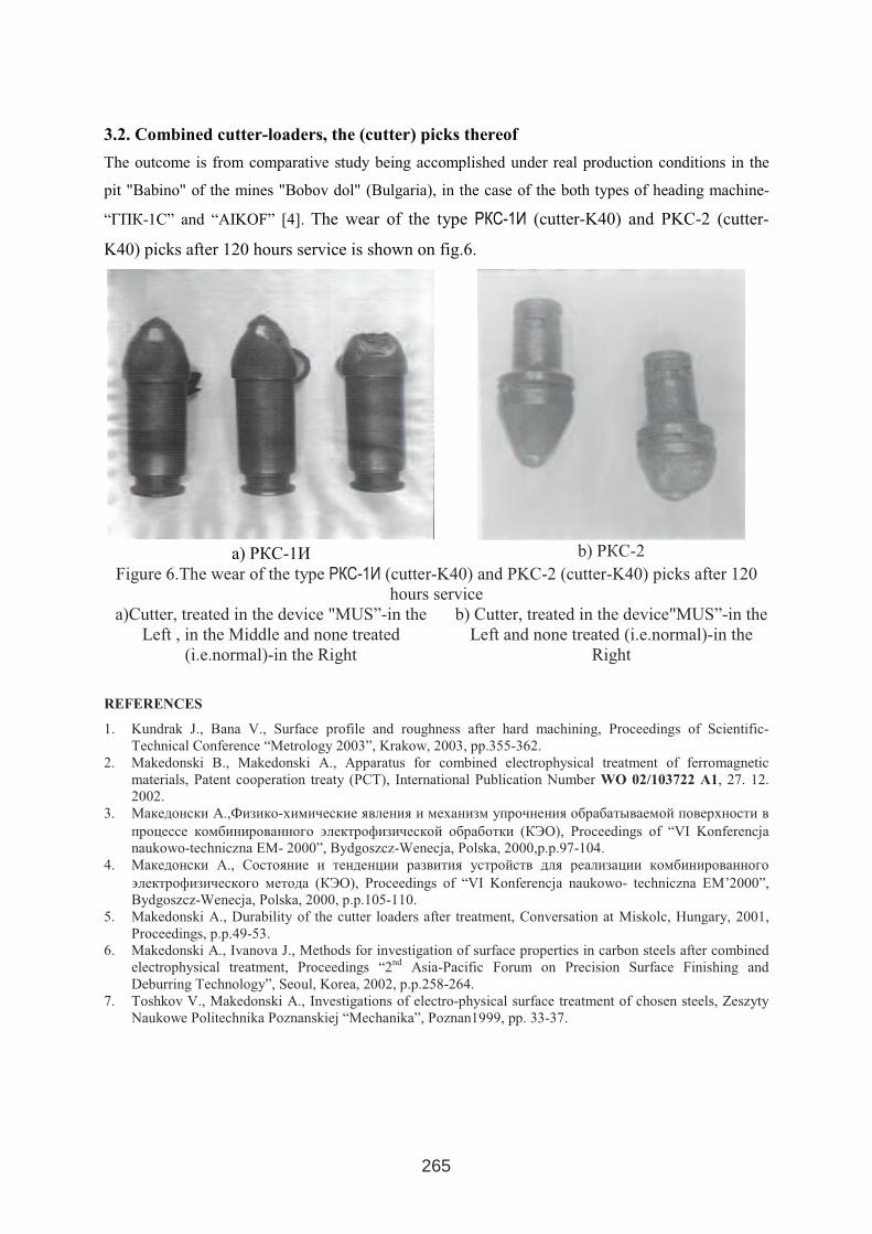
3.2. Combined cutter-loaders, the (cutter) picks thereof
The outcome is from comparative study being accomplished under real production conditions in the
pit "Babino" of the mines "Bobov dol" (Bulgaria), in the case of the both types of heading machine-
“ГПК-1С” and “AIKOF” [4]. The wear of the type РКС-1И (cutter-K40) and PKC-2 (cutter-
K40) picks after 120 hours service is shown on fig.6.
a) РКС-1И b) РКС-2
Figure 6.The wear of the type РКС-1И (cutter-K40) and PKC-2 (cutter-K40) picks after 120
hours service
a)Cutter, treated in the device "MUS”-in the
Left , in the Middle and none treated
(i.e.normal)-in the Right
b) Cutter, treated in the device"MUS”-in the
Left and none treated (i.e.normal)-in the
Right
REFERENCES
1. Kundrak J., Bana V., Surface profile and roughness after hard machining, Proceedings of Scientific-
Technical Conference “Metrology 2003”, Krakow, 2003, pp.355-362.
2. Makedonski B., Makedonski A., Apparatus for combined electrophysical treatment of ferromagnetic
materials, Patent cooperation treaty (PCT), International Publication Number WO 02/103722 A1, 27. 12.
2002.
3. Македонски А.,Физико-химические явления и механизм упрочнения обрабатываемой поверхности в
процессе комбинированного ∋лектрофизической обработки (КЭО), Proceedings of “VI Konferencja
naukowo-techniczna EM- 2000”, Bydgoszcz-Wenecja, Polska, 2000,p.p.97-104.
4. Македонски А., Состояние и тенденции развития устройств для реализации комбинированного
∋лектрофизического метода (КЭО), Proceedings of “VI Konferencja naukowo- techniczna EM’2000”,
Bydgoszcz-Wenecja, Polska, 2000, p.p.105-110.
5. Makedonski A., Durability of the cutter loaders after treatment, Conversation at Miskolc, Hungary, 2001,
Proceedings, p.p.49-53.
6. Makedonski A., Ivanova J., Methods for investigation of surface properties in carbon steels after combined
electrophysical treatment, Proceedings “2nd
Asia-Pacific Forum on Precision Surface Finishing and
Deburring Technology”, Seoul, Korea, 2002, p.p.258-264.
7. Toshkov V., Makedonski A., Investigations of electro-physical surface treatment of chosen steels, Zeszyty
Naukowe Politechnika Poznanskiej “Mechanika”, Poznan1999, pp. 33-37.
265

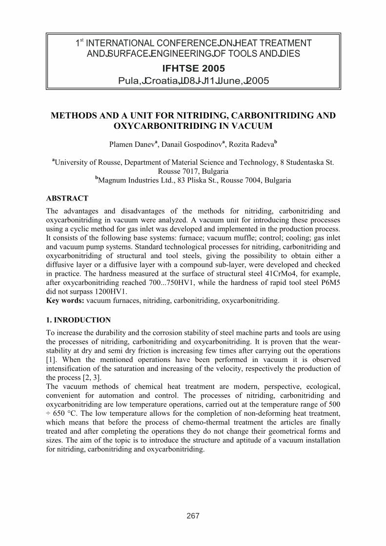
METHODS AND A UNIT FOR NITRIDING, CARBONITRIDING AND
OXYCARBONITRIDING IN VACUUM
Plamen Daneva, Danail Gospodinov
a, Rozita Radeva
b
aUniversity of Rousse, Department of Material Science and Technology, 8 Studentaska St.
Rousse 7017, BulgariabMagnum Industries Ltd., 83 Pliska St., Rousse 7004, Bulgaria
ABSTRACT
The advantages and disadvantages of the methods for nitriding, carbonitriding and
oxycarbonitriding in vacuum were analyzed. A vacuum unit for introducing these processes
using a cyclic method for gas inlet was developed and implemented in the production process.
It consists of the following base systems: furnace; vacuum muffle; control; cooling; gas inlet
and vacuum pump systems. Standard technological processes for nitriding, carbonitriding and
oxycarbonitriding of structural and tool steels, giving the possibility to obtain either a
diffusive layer or a diffusive layer with a compound sub-layer, were developed and checked
in practice. The hardness measured at the surface of structural steel 41CrMo4, for example,
after oxycarbonitriding reached 700...750HV1, while the hardness of rapid tool steel P6M5
did not surpass 1200HV1.
Key words: vacuum furnaces, nitriding, carbonitriding, oxycarbonitriding.
1. INRODUCTION
To increase the durability and the corrosion stability of steel machine parts and tools are using
the processes of nitriding, carbonitriding and oxycarbonitriding. It is proven that the wear-
stability at dry and semi dry friction is increasing few times after carrying out the operations
[1]. When the mentioned operations have been performed in vacuum it is observed
intensification of the saturation and increasing of the velocity, respectively the production of
the process [2, 3].
The vacuum methods of chemical heat treatment are modern, perspective, ecological,
convenient for automation and control. The processes of nitriding, carbonitriding and
oxycarbonitriding are low temperature operations, carried out at the temperature range of 500
÷ 650 °C. The low temperature allows for the completion of non-deforming heat treatment,
which means that before the process of chemo-thermal treatment the articles are finally
treated and after completing the operations they do not change their geometrical forms and
sizes. The aim of the topic is to introduce the structure and aptitude of a vacuum installation
for nitriding, carbonitriding and oxycarbonitriding.
1 INTERNATIONAL CONFERENCE ON HEAT TREATMENT
AND SURFACE ENGINEERING OF TOOLS AND DIES
st
Pula, Croatia 08 - 11 June, 2005,
IFHTSE 2005
267
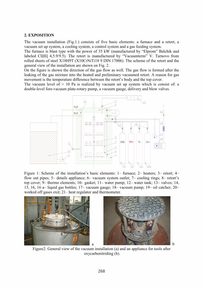
2. EXPOSITION
The vacuum installation (Fig.1.) consists of five basic elements: a furnace and a retort, a
vacuum set up system, a cooling system, a control system and a gas feeding system.
The furnace is blast type with the power of 35 kW (manufactured by “Elprom” Balchik and
labeled СШЦ 4,5.9/9.5). The retort is manufactured by “Vacuumterm” V. Tarnovo from
rolled sheets of steel X18H9T (X10CrNiTi18 9 DIN 17006). The scheme of the retort and the
general view of the installation are shown on Fig. 2.
On the figure is shown the direction of the gas flow as well. The gas flow is formed after the
leaking of the gas mixture into the heated and preliminary vacuumed retort. A reason for gas
movement is the temperature difference between the retort’s body and the top cover.
The vacuum level of ≈ 10 Pa is realized by vacuum set up system which is consist of: a
double-level fore-vacuum plate-rotary pump, a vacuum gauge, delivery and blow valves.
H2O
H2O
CO2 NH3 N2 CH4
Figure 1: Scheme of the installation’s basic elements: 1– furnace; 2– heaters; 3– retort; 4–
flow out pipes; 5– details appliance; 6– vacuum system outlet; 7– cooling rings; 8– retort’s
top cover; 9– thermo elements; 10– gasket; 11– water pump; 12– water tank; 13– valves; 14,
15, 16, 16 a– liquid gas bottles; 17– vacuum gauge; 18– vacuum pump; 19– oil catcher; 20–
worked off gases exit; 21– heat regulator and thermometer.
a b
Figure2: General view of the vacuum installation (a) and an appliance for tools after
oxycarbonitriding (b).
268
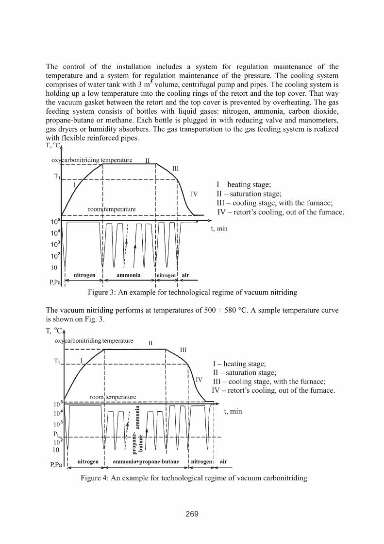
The control of the installation includes a system for regulation maintenance of the
temperature and a system for regulation maintenance of the pressure. The cooling system
comprises of water tank with 3 m3
volume, centrifugal pump and pipes. The cooling system is
holding up a low temperature into the cooling rings of the retort and the top cover. That way
the vacuum gasket between the retort and the top cover is prevented by overheating. The gas
feeding system consists of bottles with liquid gases: nitrogen, ammonia, carbon dioxide,
propane-butane or methane. Each bottle is plugged in with reducing valve and manometers,
gas dryers or humidity absorbers. The gas transportation to the gas feeding system is realized
with flexible reinforced pipes.
Figure 3: An example for technological regime of vacuum nitriding
The vacuum nitriding performs at temperatures of 500 ÷ 580 °C. A sample temperature curve
is shown on Fig. 3.
Figure 4: An example for technological regime of vacuum carbonitriding
269
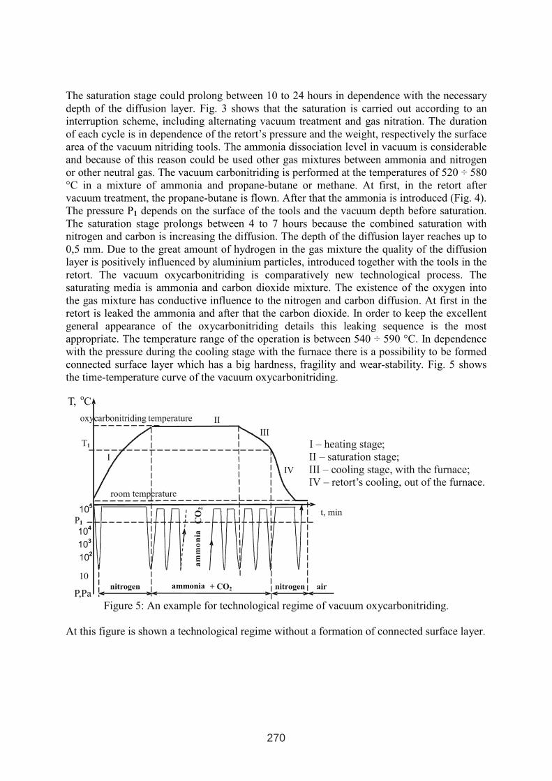
The saturation stage could prolong between 10 to 24 hours in dependence with the necessary
depth of the diffusion layer. Fig. 3 shows that the saturation is carried out according to an
interruption scheme, including alternating vacuum treatment and gas nitration. The duration
of each cycle is in dependence of the retort’s pressure and the weight, respectively the surface
area of the vacuum nitriding tools. The ammonia dissociation level in vacuum is considerable
and because of this reason could be used other gas mixtures between ammonia and nitrogen
or other neutral gas. The vacuum carbonitriding is performed at the temperatures of 520 ÷ 580
°C in a mixture of ammonia and propane-butane or methane. At first, in the retort after
vacuum treatment, the propane-butane is flown. After that the ammonia is introduced (Fig. 4).
The pressure P1 depends on the surface of the tools and the vacuum depth before saturation.
The saturation stage prolongs between 4 to 7 hours because the combined saturation with
nitrogen and carbon is increasing the diffusion. The depth of the diffusion layer reaches up to
0,5 mm. Due to the great amount of hydrogen in the gas mixture the quality of the diffusion
layer is positively influenced by aluminium particles, introduced together with the tools in the
retort. The vacuum oxycarbonitriding is comparatively new technological process. The
saturating media is ammonia and carbon dioxide mixture. The existence of the oxygen into
the gas mixture has conductive influence to the nitrogen and carbon diffusion. At first in the
retort is leaked the ammonia and after that the carbon dioxide. In order to keep the excellent
general appearance of the oxycarbonitriding details this leaking sequence is the most
appropriate. The temperature range of the operation is between 540 ÷ 590 °C. In dependence
with the pressure during the cooling stage with the furnace there is a possibility to be formed
connected surface layer which has a big hardness, fragility and wear-stability. Fig. 5 shows
the time-temperature curve of the vacuum oxycarbonitriding.
Figure 5: An example for technological regime of vacuum oxycarbonitriding.
At this figure is shown a technological regime without a formation of connected surface layer.
ammonia
270
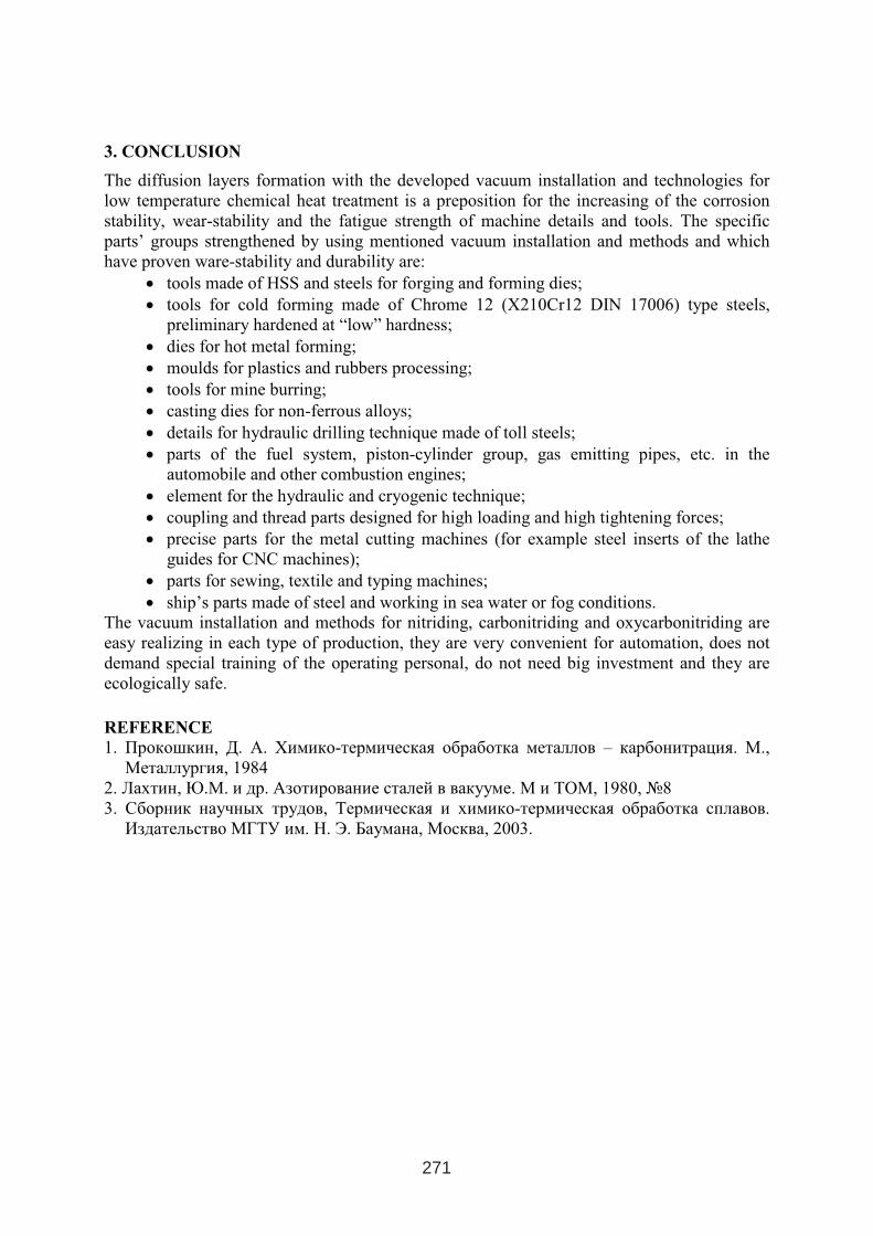
3. CONCLUSION
The diffusion layers formation with the developed vacuum installation and technologies for
low temperature chemical heat treatment is a preposition for the increasing of the corrosion
stability, wear-stability and the fatigue strength of machine details and tools. The specific
parts’ groups strengthened by using mentioned vacuum installation and methods and which
have proven ware-stability and durability are:
• tools made of HSS and steels for forging and forming dies;
• tools for cold forming made of Chrome 12 (X210Cr12 DIN 17006) type steels,
preliminary hardened at “low” hardness;
• dies for hot metal forming;
• moulds for plastics and rubbers processing;
• tools for mine burring;
• casting dies for non-ferrous alloys;
• details for hydraulic drilling technique made of toll steels;
• parts of the fuel system, piston-cylinder group, gas emitting pipes, etc. in the
automobile and other combustion engines;
• element for the hydraulic and cryogenic technique;
• coupling and thread parts designed for high loading and high tightening forces;
• precise parts for the metal cutting machines (for example steel inserts of the lathe
guides for CNC machines);
• parts for sewing, textile and typing machines;
• ship’s parts made of steel and working in sea water or fog conditions.
The vacuum installation and methods for nitriding, carbonitriding and oxycarbonitriding are
easy realizing in each type of production, they are very convenient for automation, does not
demand special training of the operating personal, do not need big investment and they are
ecologically safe.
REFERENCE
1. Прокошкин, Д. А. Химико-термическая обработка металлов – карбонитрация. М.,
Металлургия, 1984
2. Лахтин,Ю.М. и др. Азотирование сталей в вакууме.М и ТОМ, 1980, №8
3. Сборник научных трудов, Термическая и химико-термическая обработка сплавов.
Издательство МГТУ им. Н. Э. Баумана,Москва, 2003.
271

GAS NITRIDING OF EN40B STEEL WITH HIGHEST GROWTH RATE OF THE
CASE AND REDUCED WHITE LAYER FORMATION.
Shahjahan Mridha
Department of Manufacturing and Materials Engineering
International Islamic University Malaysia
Jalan Gombak 53100, Kuala Lumpur, Malaysia
Email: [email protected]
ABSTRACT
Nitriding is now a well established process for producing very hard (approximately 1000
VHN) and wear resisting surfaces on low alloy steels without any distortion and dimensional
changes. In gas nitriding the thickness of the case depth is reported to increase with the
increase of ammonia in the conventional NH3/H2 gas mixture which consequently increases
the thickness of undesirable surface iron-nitride (white layer). In this investigation the growth
kinetics of a nitrided layer have been investigated by nitriding En40B steel at 470, 520 and
570 °C for 6 to 96 hours in gaseous environments containing 10 % to 80 % ammonia. The
conditions were selected in such a way to produce nitrided specimens with and without white
layer. A metallographic technique was used to reveal different zones of the nitrided surface
and thicknesses of these zones were recorded using microscope. The nitrided layer thickness
is found to increase parabolically with increasing the processing time. The growth kinetics of
this hardened layer produced a linear relationship with nitriding potential at all temperatures
up to a certain point where a white layer formed. At 470oC the growth rate is constant where
presumably γ'-Fe4N only is present while at 520oC this constancy appears in the presence ε-
Fe3N. At 570oC the growth rate continues to increase, but not linearly, even when γ'-Fe4N is
present and constancy appears well ahead of the presence of ε-Fe3N phase. The findings
conclusively suggest that the growth rate of the nitrided layer reached to a maximum with the
increase of ammonia content in the gas mixture up to an optimum level where the thickness of
the white layer is a minimum.
Keywords: Gas nitriding, Diffusion layer, Nitriding potential, Growth rate, Compound zone,
Microhardness.
1 INTERNATIONAL CONFERENCE ON HEAT TREATMENT
AND SURFACE ENGINEERING OF TOOLS AND DIES
st
Pula, Croatia 08 - 11 June, 2005,
IFHTSE 2005
273
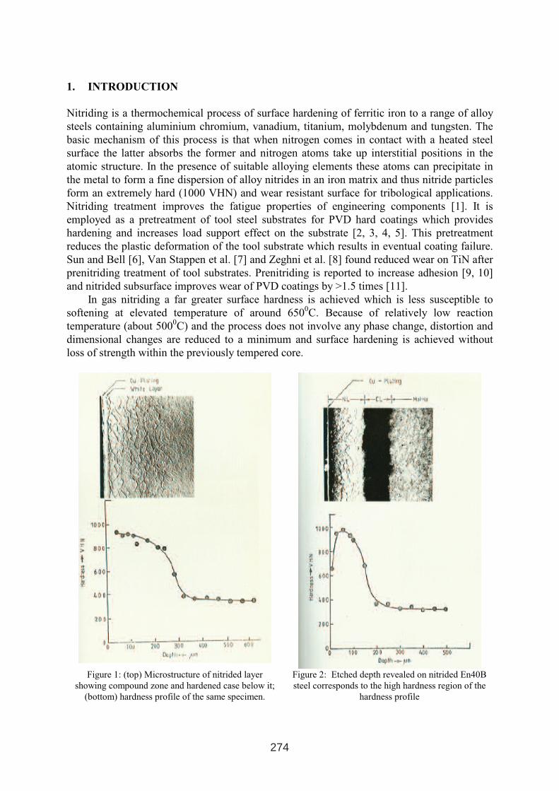
1. INTRODUCTION
Nitriding is a thermochemical process of surface hardening of ferritic iron to a range of alloy
steels containing aluminium chromium, vanadium, titanium, molybdenum and tungsten. The
basic mechanism of this process is that when nitrogen comes in contact with a heated steel
surface the latter absorbs the former and nitrogen atoms take up interstitial positions in the
atomic structure. In the presence of suitable alloying elements these atoms can precipitate in
the metal to form a fine dispersion of alloy nitrides in an iron matrix and thus nitride particles
form an extremely hard (1000 VHN) and wear resistant surface for tribological applications.
Nitriding treatment improves the fatigue properties of engineering components [1]. It is
employed as a pretreatment of tool steel substrates for PVD hard coatings which provides
hardening and increases load support effect on the substrate [2, 3, 4, 5]. This pretreatment
reduces the plastic deformation of the tool substrate which results in eventual coating failure.
Sun and Bell [6], Van Stappen et al. [7] and Zeghni et al. [8] found reduced wear on TiN after
prenitriding treatment of tool substrates. Prenitriding is reported to increase adhesion [9, 10]
and nitrided subsurface improves wear of PVD coatings by >1.5 times [11].
In gas nitriding a far greater surface hardness is achieved which is less susceptible to
softening at elevated temperature of around 6500C. Because of relatively low reaction
temperature (about 5000C) and the process does not involve any phase change, distortion and
dimensional changes are reduced to a minimum and surface hardening is achieved without
loss of strength within the previously tempered core.
Figure 1: (top) Microstructure of nitrided layer
showing compound zone and hardened case below it;
(bottom) hardness profile of the same specimen.
Figure 2: Etched depth revealed on nitrided En40B
steel corresponds to the high hardness region of the
hardness profile
274
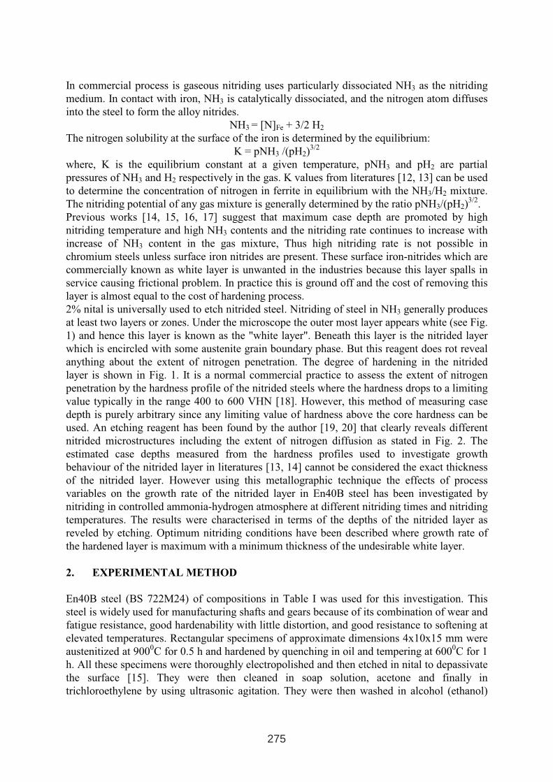
In commercial process is gaseous nitriding uses particularly dissociated NH3 as the nitriding
medium. In contact with iron, NH3 is catalytically dissociated, and the nitrogen atom diffuses
into the steel to form the alloy nitrides.
NH3 = [N]Fe + 3/2 H2
The nitrogen solubility at the surface of the iron is determined by the equilibrium:
K = pNH3 /(pH2)3/2
where, K is the equilibrium constant at a given temperature, pNH3 and pH2 are partial
pressures of NH3 and H2 respectively in the gas. K values from literatures [12, 13] can be used
to determine the concentration of nitrogen in ferrite in equilibrium with the NH3/H2 mixture.
The nitriding potential of any gas mixture is generally determined by the ratio pNH3/(pH2)3/2
.
Previous works [14, 15, 16, 17] suggest that maximum case depth are promoted by high
nitriding temperature and high NH3 contents and the nitriding rate continues to increase with
increase of NH3 content in the gas mixture, Thus high nitriding rate is not possible in
chromium steels unless surface iron nitrides are present. These surface iron-nitrides which are
commercially known as white layer is unwanted in the industries because this layer spalls in
service causing frictional problem. In practice this is ground off and the cost of removing this
layer is almost equal to the cost of hardening process.
2% nital is universally used to etch nitrided steel. Nitriding of steel in NH3 generally produces
at least two layers or zones. Under the microscope the outer most layer appears white (see Fig.
1) and hence this layer is known as the "white layer". Beneath this layer is the nitrided layer
which is encircled with some austenite grain boundary phase. But this reagent does rot reveal
anything about the extent of nitrogen penetration. The degree of hardening in the nitrided
layer is shown in Fig. 1. It is a normal commercial practice to assess the extent of nitrogen
penetration by the hardness profile of the nitrided steels where the hardness drops to a limiting
value typically in the range 400 to 600 VHN [18]. However, this method of measuring case
depth is purely arbitrary since any limiting value of hardness above the core hardness can be
used. An etching reagent has been found by the author [19, 20] that clearly reveals different
nitrided microstructures including the extent of nitrogen diffusion as stated in Fig. 2. The
estimated case depths measured from the hardness profiles used to investigate growth
behaviour of the nitrided layer in literatures [13, 14] cannot be considered the exact thickness
of the nitrided layer. However using this metallographic technique the effects of process
variables on the growth rate of the nitrided layer in En40B steel has been investigated by
nitriding in controlled ammonia-hydrogen atmosphere at different nitriding times and nitriding
temperatures. The results were characterised in terms of the depths of the nitrided layer as
reveled by etching. Optimum nitriding conditions have been described where growth rate of
the hardened layer is maximum with a minimum thickness of the undesirable white layer.
2. EXPERIMENTAL METHOD
En40B steel (BS 722M24) of compositions in Table I was used for this investigation. This
steel is widely used for manufacturing shafts and gears because of its combination of wear and
fatigue resistance, good hardenability with little distortion, and good resistance to softening at
elevated temperatures. Rectangular specimens of approximate dimensions 4x10x15 mm were
austenitized at 9000C for 0.5 h and hardened by quenching in oil and tempering at 600
0C for 1
h. All these specimens were thoroughly electropolished and then etched in nital to depassivate
the surface [15]. They were then cleaned in soap solution, acetone and finally in
trichloroethylene by using ultrasonic agitation. They were then washed in alcohol (ethanol)
275
and dried on soft tissue before nitriding. These were the standard heat treatment and specimen
preparation processes.
A horizontal nitriding furnace having a recrystallized alumina reaction tube was used for
nitriding experiments. Specimens were nitrided in a controlled ammonia-hydrogen
atmosphere at 470, 520 and 570 °C for 6 to 96 h in 10 to 80 % NH3. After nitriding the
specimens were furnace cooled at a position under the water cooling coil at the end of the
reaction tube. These nitrided specimens were then electroplated with nickel and copper in
order to preserve the edge of the specimens, which tend to break up during polishing of
mounted cross sections. It was found that copper plating alone on the nitrided surface does not
adhere firmly, whereas nickel does. A problem with nickel plating was, however, the
difficulty in distinguishing between it and the compound zone of the nitrided specimens. 2
mm were then ground off the edge of the plated samples, which were then mounted and
polished by standard metallographic techniques.
Table I: Chemical compositions (in wt %) of the steel investigated
C Cr Mo Ni V Al Si* Mn
0.26 2.88 0.53 0.40 0.60 - 0.1-0.35 0.4-0.65
(S= 0.05% and P = 0.05% in each steels), * Specification only.
The nitrided layer depths were revealed by the action of Oberhoffer's reagent (1g cupric
chloride, 30g ferric chloride, 0.5g stanneous chloride, 50ml HCl, 500ml water, 500ml ethyl
alcohol). This reagent also dissolves the ε-Fe3N phase but not the γ′-Fe4N phase [19]. So this
etching technique was also used to detect the presence of compound layer phases. The depth
of the nitrided layer in the microstructure was measured using a micrometer eyepiece fitted to
a Reichert projection microscope. Microhardness measurements were made on specimens in
the polished and unetched conditions, using a 50 g load and a microhardness attachment to the
Reichert.
3. RESULTS AND DISCUSSION
3.1 Process parameters and growth of the nitrided layer
Fig. 3 represents the relationship between the square of the nitrided layer thickness and
nitriding time at different nitriding potentials and temperatures. In all cases the growth of the
nitrided layer is parabolic and depth increases with increasing nitriding temperature and
nitriding potential. The figures also show that the difference between slopes of the curves of
30% and 80% NH3 is quite small.
The effect of nitriding potential on diffusion layer growth rate was investigated by nitriding at
520oC for 48 h and the results are presented as depth squared versus nitriding potential in Fig.
4. Phase present in the compound zone is also incorporated in this plot. The results show that
the nitrided layer depth increases with increase of nitriding potential even when γ′-Fe4N is
present, but once ε-Fe3N forms, the nitriding rate remains constant.
276
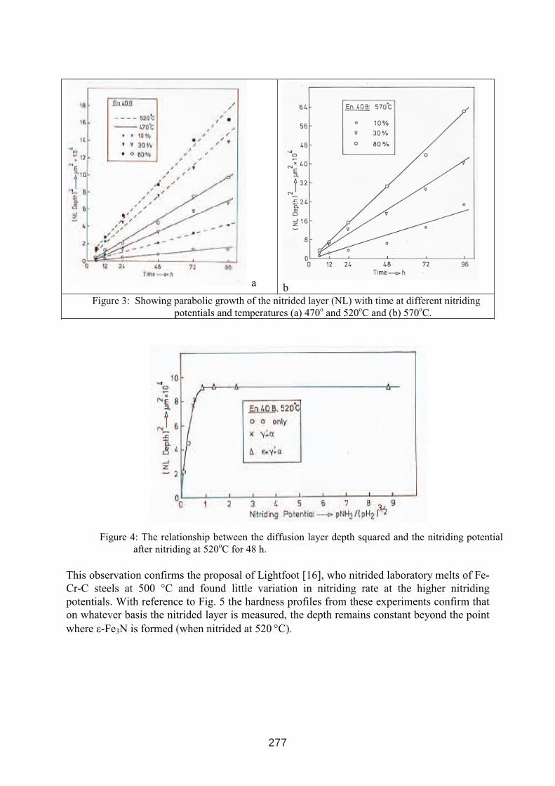
a b
Figure 3: Showing parabolic growth of the nitrided layer (NL) with time at different nitriding
potentials and temperatures (a) 470o
and 520oC and (b) 570
oC.
Figure 4: The relationship between the diffusion layer depth squared and the nitriding potential
after nitriding at 520oC for 48 h.
This observation confirms the proposal of Lightfoot [16], who nitrided laboratory melts of Fe-
Cr-C steels at 500 °C and found little variation in nitriding rate at the higher nitriding
potentials. With reference to Fig. 5 the hardness profiles from these experiments confirm that
on whatever basis the nitrided layer is measured, the depth remains constant beyond the point
where ε-Fe3N is formed (when nitrided at 520 °C).
277
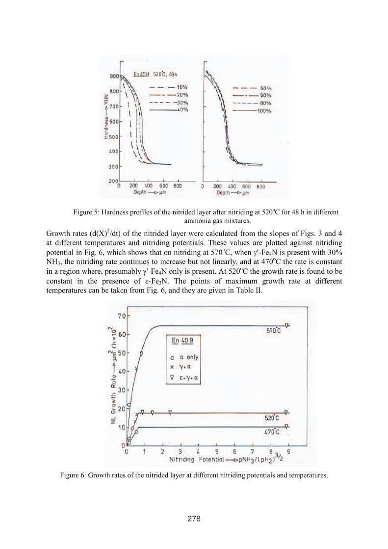
Figure 5: Hardness profiles of the nitrided layer after nitriding at 520oC for 48 h in different
ammonia gas mixtures.
Growth rates (d(X)2/dt) of the nitrided layer were calculated from the slopes of Figs. 3 and 4
at different temperatures and nitriding potentials. These values are plotted against nitriding
potential in Fig. 6, which shows that on nitriding at 570oC, when γ′-Fe4N is present with 30%
NH3, the nitriding rate continues to increase but not linearly, and at 470oC the rate is constant
in a region where, presumably γ′-Fe4N only is present. At 520oC the growth rate is found to be
constant in the presence of ε-Fe3N. The points of maximum growth rate at different
temperatures can be taken from Fig. 6, and they are given in Table II.
278
Figure 6: Growth rates of the nitrided layer at different nitriding potentials and temperatures.
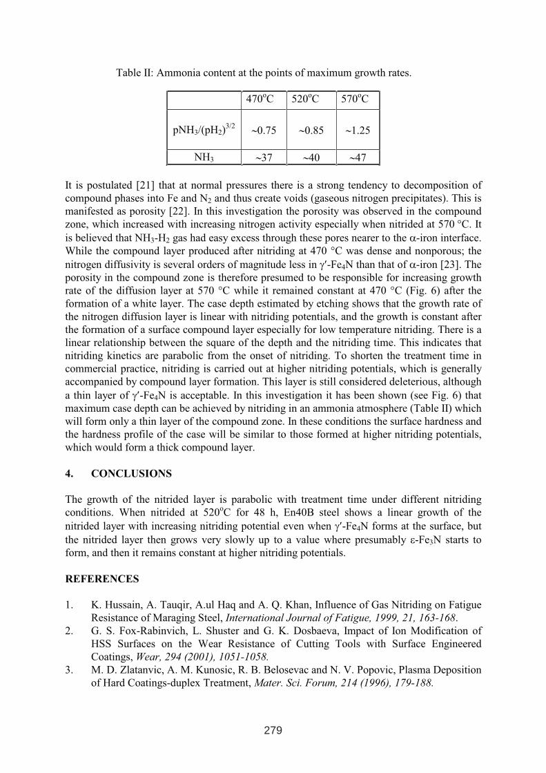
470oC 520
oC 570
oC
pNH3/(pH2)3/2 ∼0.75 ∼0.85 ∼1.25
NH3 ∼37 ∼40 ∼47
It is postulated [21] that at normal pressures there is a strong tendency to decomposition of
compound phases into Fe and N2 and thus create voids (gaseous nitrogen precipitates). This is
manifested as porosity [22]. In this investigation the porosity was observed in the compound
zone, which increased with increasing nitrogen activity especially when nitrided at 570 °C. It
is believed that NH3-H2 gas had easy excess through these pores nearer to the α-iron interface.
While the compound layer produced after nitriding at 470 °C was dense and nonporous; the
nitrogen diffusivity is several orders of magnitude less in γ′-Fe4N than that of α-iron [23]. The
porosity in the compound zone is therefore presumed to be responsible for increasing growth
rate of the diffusion layer at 570 °C while it remained constant at 470 °C (Fig. 6) after the
formation of a white layer. The case depth estimated by etching shows that the growth rate of
the nitrogen diffusion layer is linear with nitriding potentials, and the growth is constant after
the formation of a surface compound layer especially for low temperature nitriding. There is a
linear relationship between the square of the depth and the nitriding time. This indicates that
nitriding kinetics are parabolic from the onset of nitriding. To shorten the treatment time in
commercial practice, nitriding is carried out at higher nitriding potentials, which is generally
accompanied by compound layer formation. This layer is still considered deleterious, although
a thin layer of γ′-Fe4N is acceptable. In this investigation it has been shown (see Fig. 6) that
maximum case depth can be achieved by nitriding in an ammonia atmosphere (Table II) which
will form only a thin layer of the compound zone. In these conditions the surface hardness and
the hardness profile of the case will be similar to those formed at higher nitriding potentials,
which would form a thick compound layer.
4. CONCLUSIONS
The growth of the nitrided layer is parabolic with treatment time under different nitriding
conditions. When nitrided at 520oC for 48 h, En40B steel shows a linear growth of the
nitrided layer with increasing nitriding potential even when γ′-Fe4N forms at the surface, but
the nitrided layer then grows very slowly up to a value where presumably ε-Fe3N starts to
form, and then it remains constant at higher nitriding potentials.
REFERENCES
1. K. Hussain, A. Tauqir, A.ul Haq and A. Q. Khan, Influence of Gas Nitriding on Fatigue
Resistance of Maraging Steel, International Journal of Fatigue, 1999, 21, 163-168.
2. G. S. Fox-Rabinvich, L. Shuster and G. K. Dosbaeva, Impact of Ion Modification of
HSS Surfaces on the Wear Resistance of Cutting Tools with Surface Engineered
Coatings, Wear, 294 (2001), 1051-1058.
3. M. D. Zlatanvic, A. M. Kunosic, R. B. Belosevac and N. V. Popovic, Plasma Deposition
of Hard Coatings-duplex Treatment, Mater. Sci. Forum, 214 (1996), 179-188.
279
Table II: Ammonia content at the points of maximum growth rates.
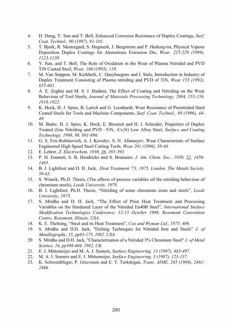
4. H. Dong, Y. Sun and T. Bell, Enhanced Corrosion Resistance of Duplex Coatings, Surf.
Coat. Technol., 90 (1997), 91-101.
5. T. Bjork, R. Mestergard, S. Hogmerk, J. Bergstrom and P. Hedenqvist, Physical Vapour
Deposition Duplex Coatings for Aluminium Extrusion Die, Wear, 225-229 (1999),
1123-1130.
6. Y. Sun, and T. Bell, The Role of Oxidation in the Wear of Plasma Nitrided and PVD
TiN Coated Steel, Wear, 166 (1993), 119.
7. M. Van Stappen, M. Kerkhofs, C. Qaeyhaegens and I. Stals, Introduction in Industry of
Duplex Treatment Consisting of Plasma nitriding and PVD of TiN, Wear 153 (1992),
655-661.
8. A. E. Zeghni and M. S. J. Hashmi, The Effect of Coating and Nitriding on the Wear
Behaviour of Tool Steels, Journal of Materials Processing Technology, 2004, 155-156,
1918-1922.
9. K. Hock, H. J. Spies, B. Larich and G. Leonhardt, Wear Resistance of Prenitrided Hard
Coated Steels for Tools and Machine Components, Surf. Coat. Technol., 88 (1996), 44-
49.
10. M. Bader, H. J. Spies, K. Hock, E. Broszeit and H. J. Schroder, Properties of Duplex
Treated (Gas Nitriding and PVD –TiN, -Cr2N) Low Alloy Steel, Surface and Coating
Technology, 1998, 98, 891-896.
11. G. S. Fox-Robinovich, A. I. Kovalev, S. N. Afanasyev, Wear Characteristic of Surface
Engineered High Speed Steel Cutting Tools, Wear 201 (1996), 38-44.
12. E. Lehrer, Z. Electrochem, 1930, 36, 385-393.
13. P. H. Emmett, S. B. Hendricks and S. Brunauer, J. Am. Chem. Soc., 1930, 52, 1456-
1465.
14. B. J. Lightfoot and D. H. Jack,. Heat Treatment '73, 1975, London, The Metals Society,
59-65.
15. S. Winnik, Ph.D. Thesis, (The effects of process variables oil the nitriding behaviour of
chromium steels), Leeds University, 1979.
16. B. J. Lightfoot, Ph.D. Thesis, “Nitriding of some chromium irons and steels”, Leeds
University, 1973.
17. S. Mridha and D. H. Jack, “The Effect of Prior Heat Treatment and Processing
Variables on the Hardened Layer of the Nitrided En40B Steel”, International Surface
Modification Technologies Conference, 12-15 October 1998, Rosemont Convention
Centre, Rosemont, Illinois, USA.
18. K. E. Thelning, “Steel and its Heat Treatment”, Cox and Wyman Ltd., 1975, 406.
19. S. Mridha and D.H. Jack, "Etching Techniques for Nitrided Iron and Steels" J. of
Metallography, 15, pp63-175, 1982, USA.
20 S. Mridha and D.H. Jack, "Characterization of a Nitrided 3% Chromium Steel" J. of Metal
Science, 16, pp398-404, 1982, UK
21. E. J. Mittemeijer and M. A. J. Somers, Surface Engineering, 13 (1997), 483-497.
22. M. A. J. Somers and E. J. Mittemeijer, Surface Engineering, 3 (1987), 123-137.
23. K. Schwerdtfeger, P. Grieveson and E. T. Turkdogan, Trans. AIME, 245 (1969), 2461-
2466.
280
IMPROVEMENTS IN THERMO REACTIVE DEPOSITION OF CARBIDE
LAYERS
Božidar Matijević, Mladen Stupnišek
University of Zagreb, Faculty of Mechanical Engineering and Naval Architecture
Ivana Lučića 5, 10.000 Zagreb, Croatia
ABSTRACT
This paper presents developments contributing to the improvement of the process of
producing hard carbide layers, with special attention paid to the application on tools
and dies. The quantitative impact of the chemical composition of the steel and the
process temperature on the kinetics of the carbide layer formation has been
determined. In conventional processes of diffusion formation of carbide layers the
phenomenon of partial de-carburization of steel occurring beneath the carbide layer
during the process of its formation has been dealt with by the introduction of
controlled pre-carburization. Diffusion formation of carbide layers has been improved
by the development of duplex processes which enable the formation of a case
hardened layer which is harder than the core. Thus, the substrate for the hard and
brittle carbide layer is improved. The developed improvements should contribute to
the improvement of properties of the surface layers produced by the diffusion
formation of carbide layers. In this way this process can be applied to the
manufacturing of tools and dies.
Key words: diffusion carbide layer, vanadium carbide, duplex treatment, tools, dies
1 INTERNATIONAL CONFERENCE ON HEAT TREATMENT
AND SURFACE ENGINEERING OF TOOLS AND DIES
st
Pula, Croatia 08 - 11 June, 2005,
IFHTSE 2005
281
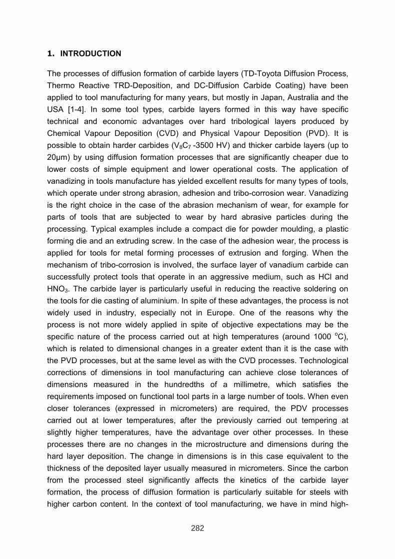
1. INTRODUCTION
The processes of diffusion formation of carbide layers (TD-Toyota Diffusion Process,
Thermo Reactive TRD-Deposition, and DC-Diffusion Carbide Coating) have been
applied to tool manufacturing for many years, but mostly in Japan, Australia and the
USA [1-4]. In some tool types, carbide layers formed in this way have specific
technical and economic advantages over hard tribological layers produced by
Chemical Vapour Deposition (CVD) and Physical Vapour Deposition (PVD). It is
possible to obtain harder carbides (V8C7 -3500 HV) and thicker carbide layers (up to
20µm) by using diffusion formation processes that are significantly cheaper due to
lower costs of simple equipment and lower operational costs. The application of
vanadizing in tools manufacture has yielded excellent results for many types of tools,
which operate under strong abrasion, adhesion and tribo-corrosion wear. Vanadizing
is the right choice in the case of the abrasion mechanism of wear, for example for
parts of tools that are subjected to wear by hard abrasive particles during the
processing. Typical examples include a compact die for powder moulding, a plastic
forming die and an extruding screw. In the case of the adhesion wear, the process is
applied for tools for metal forming processes of extrusion and forging. When the
mechanism of tribo-corrosion is involved, the surface layer of vanadium carbide can
successfully protect tools that operate in an aggressive medium, such as HCl and
HNO3. The carbide layer is particularly useful in reducing the reactive soldering on
the tools for die casting of aluminium. In spite of these advantages, the process is not
widely used in industry, especially not in Europe. One of the reasons why the
process is not more widely applied in spite of objective expectations may be the
specific nature of the process carried out at high temperatures (around 1000 oC),
which is related to dimensional changes in a greater extent than it is the case with
the PVD processes, but at the same level as with the CVD processes. Technological
corrections of dimensions in tool manufacturing can achieve close tolerances of
dimensions measured in the hundredths of a millimetre, which satisfies the
requirements imposed on functional tool parts in a large number of tools. When even
closer tolerances (expressed in micrometers) are required, the PDV processes
carried out at lower temperatures, after the previously carried out tempering at
slightly higher temperatures, have the advantage over other processes. In these
processes there are no changes in the microstructure and dimensions during the
hard layer deposition. The change in dimensions is in this case equivalent to the
thickness of the deposited layer usually measured in micrometers. Since the carbon
from the processed steel significantly affects the kinetics of the carbide layer
formation, the process of diffusion formation is particularly suitable for steels with
higher carbon content. In the context of tool manufacturing, we have in mind high-
282
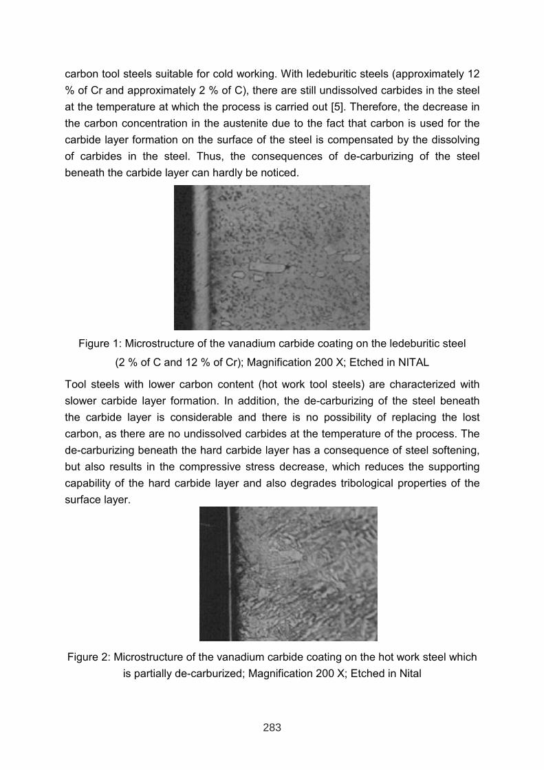
carbon tool steels suitable for cold working. With ledeburitic steels (approximately 12
% of Cr and approximately 2 % of C), there are still undissolved carbides in the steel
at the temperature at which the process is carried out [5]. Therefore, the decrease in
the carbon concentration in the austenite due to the fact that carbon is used for the
carbide layer formation on the surface of the steel is compensated by the dissolving
of carbides in the steel. Thus, the consequences of de-carburizing of the steel
beneath the carbide layer can hardly be noticed.
Figure 1: Microstructure of the vanadium carbide coating on the ledeburitic steel
(2 % of C and 12 % of Cr); Magnification 200 X; Etched in NITAL
Tool steels with lower carbon content (hot work tool steels) are characterized with
slower carbide layer formation. In addition, the de-carburizing of the steel beneath
the carbide layer is considerable and there is no possibility of replacing the lost
carbon, as there are no undissolved carbides at the temperature of the process. The
de-carburizing beneath the hard carbide layer has a consequence of steel softening,
but also results in the compressive stress decrease, which reduces the supporting
capability of the hard carbide layer and also degrades tribological properties of the
surface layer.
Figure 2: Microstructure of the vanadium carbide coating on the hot work steel which
is partially de-carburized; Magnification 200 X; Etched in Nital
283
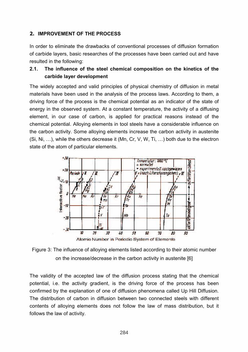
2. IMPROVEMENT OF THE PROCESS
In order to eliminate the drawbacks of conventional processes of diffusion formation
of carbide layers, basic researches of the processes have been carried out and have
resulted in the following:
2.1. The influence of the steel chemical composition on the kinetics of the
carbide layer development
The widely accepted and valid principles of physical chemistry of diffusion in metal
materials have been used in the analysis of the process laws. According to them, a
driving force of the process is the chemical potential as an indicator of the state of
energy in the observed system. At a constant temperature, the activity of a diffusing
element, in our case of carbon, is applied for practical reasons instead of the
chemical potential. Alloying elements in tool steels have a considerable influence on
the carbon activity. Some alloying elements increase the carbon activity in austenite
(Si, Ni, …), while the others decrease it (Mn, Cr, V, W, Ti, …) both due to the electron
state of the atom of particular elements.
Figure 3: The influence of alloying elements listed according to their atomic number
on the increase/decrease in the carbon activity in austenite [6]
The validity of the accepted law of the diffusion process stating that the chemical
potential, i.e. the activity gradient, is the driving force of the process has been
confirmed by the explanation of one of diffusion phenomena called Up Hill Diffusion.
The distribution of carbon in diffusion between two connected steels with different
contents of alloying elements does not follow the law of mass distribution, but it
follows the law of activity.
284
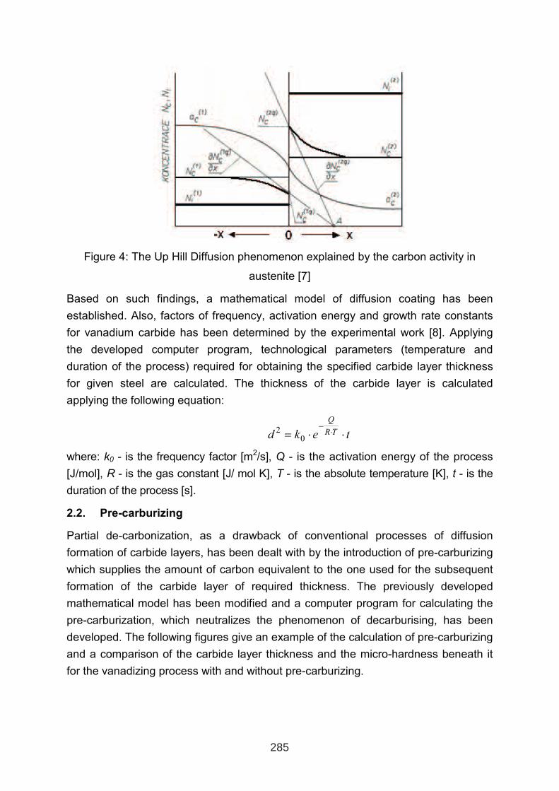
Figure 4: The Up Hill Diffusion phenomenon explained by the carbon activity in
austenite [7]
Based on such findings, a mathematical model of diffusion coating has been
established. Also, factors of frequency, activation energy and growth rate constants
for vanadium carbide has been determined by the experimental work [8]. Applying
the developed computer program, technological parameters (temperature and
duration of the process) required for obtaining the specified carbide layer thickness
for given steel are calculated. The thickness of the carbide layer is calculated
applying the following equation:
tekd TR
Q
⋅⋅=⋅
−
02
where: k0 - is the frequency factor [m2/s], Q - is the activation energy of the process
[J/mol], R - is the gas constant [J/ mol K], T - is the absolute temperature [K], t - is the
duration of the process [s].
2.2. Pre-carburizing
Partial de-carbonization, as a drawback of conventional processes of diffusion
formation of carbide layers, has been dealt with by the introduction of pre-carburizing
which supplies the amount of carbon equivalent to the one used for the subsequent
formation of the carbide layer of required thickness. The previously developed
mathematical model has been modified and a computer program for calculating the
pre-carburization, which neutralizes the phenomenon of decarburising, has been
developed. The following figures give an example of the calculation of pre-carburizing
and a comparison of the carbide layer thickness and the micro-hardness beneath it
for the vanadizing process with and without pre-carburizing.
285
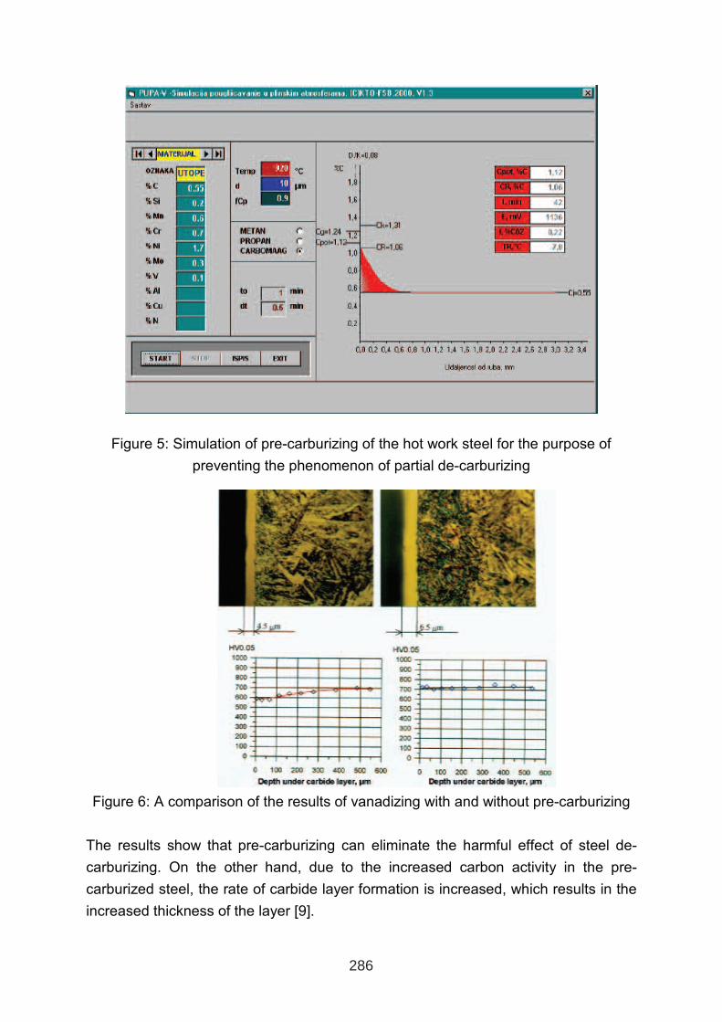
Figure 5: Simulation of pre-carburizing of the hot work steel for the purpose of
preventing the phenomenon of partial de-carburizing
Figure 6: A comparison of the results of vanadizing with and without pre-carburizing
The results show that pre-carburizing can eliminate the harmful effect of steel de-
carburizing. On the other hand, due to the increased carbon activity in the pre-
carburized steel, the rate of carbide layer formation is increased, which results in the
increased thickness of the layer [9].
286
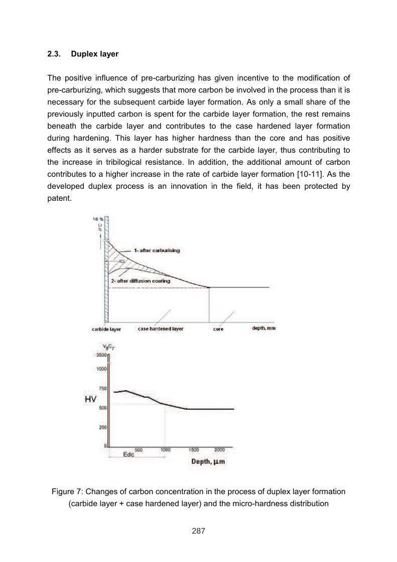
2.3. Duplex layer
The positive influence of pre-carburizing has given incentive to the modification of
pre-carburizing, which suggests that more carbon be involved in the process than it is
necessary for the subsequent carbide layer formation. As only a small share of the
previously inputted carbon is spent for the carbide layer formation, the rest remains
beneath the carbide layer and contributes to the case hardened layer formation
during hardening. This layer has higher hardness than the core and has positive
effects as it serves as a harder substrate for the carbide layer, thus contributing to
the increase in tribilogical resistance. In addition, the additional amount of carbon
contributes to a higher increase in the rate of carbide layer formation [10-11]. As the
developed duplex process is an innovation in the field, it has been protected by
patent.
Figure 7: Changes of carbon concentration in the process of duplex layer formation
(carbide layer + case hardened layer) and the micro-hardness distribution
287

3. CONCLUSION
The Processes, which eliminate the drawbacks of conventional processes of diffusion
formation of carbide layers and further improve their properties, have been
developed on the basis of researches into the theoretical laws of the process. A
computer program for the calculation of the formation rate of vanadium carbide layer
has been developed and two variants of pre-carburising have been introduced. Both
variants contribute to the increase in the rate of carbide layer formation. The first
variant of pre-carburizing eliminates the phenomenon of de-carburizing, while the
second one provides good additional support to the carbide layer by means of a case
hardened intermediate layer. These improvements should contribute to a wider
application of the process, which has comparable advantages over other surface
treatment processes.
REFERENCES
1. H. Fujita, T. Arai, Proceedings of the 4th Int. Congress of IFHT, Berlin 1985., p.
1109-1124.
2. S. B. Fazluddin, A. Koursaris. C. Ringas, K. Cowie: Formation of VC Coating on Steel Substrates in Molten Borax, Surface Modification Technologies VI, Minerals
Metals and Materials Society, 1993., 45-60.
3. B. Štefotič, J. Vižintin, F. Grobelšek, M. Stupnišek, Proceedings “Tribologija v teoriji
in praksi”, Ljubljana 1996, p. 233-241.
4. T. Arai, J. Heat Treating, Vol. 1, Nr.2, p. 15-22.
5. G.A. Roberts, J. C. Hamaker, A. R. Johnson: Tool Stees, ASM, Metals Park, Ohio
1962.
6. Eckstein at al: Technologie der Wärmebehandlung von Stahl, VEB Deutscher
Verlag für Grundstoffindustrie, Leipzig 1976.
7. Karel Stránský: Termodynamika kvazistacionární difúze uhlíku v ocelích a její
aplikace, ACADEMIA, Praha 1977.
8. B. Matijević: PhD. Thesis, University of Zagreb, Zagreb 1997.
9. B. Matijević: Influence of Chemical Composition of Steel on Diffusion Carbide
Layer Formating, Strojarstvo 43(1-3)(2001), 17-21.
10. M Stupnišek, B. Matijević: New Duplex Diffusion Coating Process, Proceedings
of the 8th Seminar of IFHTSE 2001, Dubrovnik 2001., 209-216.
11. B. Matijević, M. Stupnišek: Diffusion Forming of Carbide Layers to Reduce
Abrasive Wear, CD Proceedings of MT2002, Dublin 2002.
288
A NEW APPROACH TO LIFETIME INCREASE OF TOOLS AND DIES
BY OPTIMIZED VACUUM HARDENING AND PLASMA ASSISTED
SURFACE TREATMENT PROCESSES
Thomas Müller, Rübig Engineering GmbH&Co KG
Volker Strobl, Rübig Hardening GmbH&Co KG
Roland Kullmer, Rübig Engineering GmbH&Co KG
Monika Stoiber, Montanuniversität Leoben
ABSTRACT
Due to increased demands on tools on the one hand and the increased costs for steels and
tooling on the other hand an optimisation of lifetime and therefore of the profile of
mechanical properties of tools is indispensable. On the example of the production of a forging
die an alternative solution to new, more expensive alloys will be demonstrated.
By the development and application of new vacuum hardening processes as helium quenching
and the use of newest surface modification technologies as plasma nitriding and plasma
assisted coating technologies, properties as hardening distortion, toughness and wear
resistance can be improved and an upgrade of the tools can be achieved.
Keywords: vacuum hardening, helium quenching, plasma nitriding, plasma assisted
chemical vapour deposition, PACVD, forging, coating
1. INTRODUCTION
To optimise the performance and lifetime of tools and dies with vacuum hardening and
surface modifications by heat treatment processes as plasmanitriding, coating, carburising, it
is necessary to know exactly the application conditions.
Based on the knowledge about wear mechanism/time-temperature load/mechanical load, it is
possible to design a heat treatment sequence, which allows the utilization of the full range of
the mechanical property capacity of the used alloys.
Hereby not only the choice of the “right” hardening for the chosen steel quality is the road to
success, but the adaptation of the heat treatment to the application (wear system,..) and the
subsequent surface treatment has to be considered.
Altogether to get high quality tools or dies it is necessary to know the working conditions of
the application. With this information the heat treater is in a position to offer the proper heat
treatment. This know-how exchange is only possible, if there is cooperation between the
designer, steel supplier, manufacturer and the responsible heat treater.
1 INTERNATIONAL CONFERENCE ON HEAT TREATMENT
AND SURFACE ENGINEERING OF TOOLS AND DIES
st
Pula, Croatia 08 - 11 June, 2005,
IFHTSE 2005
289
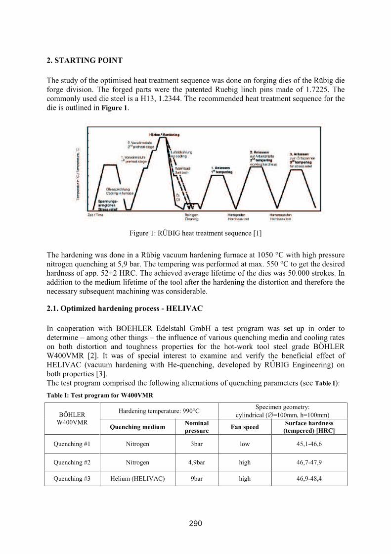
2. STARTING POINT
The study of the optimised heat treatment sequence was done on forging dies of the Rübig die
forge division. The forged parts were the patented Ruebig linch pins made of 1.7225. The
commonly used die steel is a H13, 1.2344. The recommended heat treatment sequence for the
die is outlined in Figure 1.
Figure 1: RÜBIG heat treatment sequence [1]
The hardening was done in a Rübig vacuum hardening furnace at 1050 °C with high pressure
nitrogen quenching at 5,9 bar. The tempering was performed at max. 550 °C to get the desired
hardness of app. 52+2 HRC. The achieved average lifetime of the dies was 50.000 strokes. In
addition to the medium lifetime of the tool after the hardening the distortion and therefore the
necessary subsequent machining was considerable.
2.1. Optimized hardening process - HELIVAC
In cooperation with BOEHLER Edelstahl GmbH a test program was set up in order to
determine – among other things – the influence of various quenching media and cooling rates
on both distortion and toughness properties for the hot-work tool steel grade BŐHLER
W400VMR [2]. It was of special interest to examine and verify the beneficial effect of
HELIVAC (vacuum hardening with He-quenching, developed by RŰBIG Engineering) on
both properties [3].
The test program comprised the following alternations of quenching parameters (see Table I):
Table I: Test program for W400VMR
Hardening temperature: 990°C Specimen geometry:
cylindrical (∅=100mm, h=100mm) BŐHLER
W400VMR Quenching medium
Nominal
pressure Fan speed
Surface hardness
(tempered) [HRC]
Quenching #1 Nitrogen 3bar low 45,1-46,6
Quenching #2 Nitrogen 4,9bar high 46,7-47,9
Quenching #3 Helium (HELIVAC) 9bar high 46,9-48,4
290
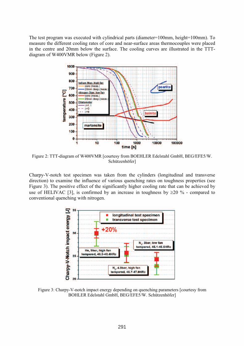
The test program was executed with cylindrical parts (diameter=100mm, height=100mm). To
measure the different cooling rates of core and near-surface areas thermocouples were placed
in the centre and 20mm below the surface. The cooling curves are illustrated in the TTT-
diagram of W400VMR below (Figure 2).
Figure 2: TTT-diagram of W400VMR [courtesy from BOEHLER Edelstahl GmbH, BEG/EFE5/W.
Schützenhöfer]
Charpy-V-notch test specimen was taken from the cylinders (longitudinal and transverse
direction) to examine the influence of various quenching rates on toughness properties (see
Figure 3). The positive effect of the significantly higher cooling rate that can be achieved by
use of HELIVAC [3], is confirmed by an increase in toughness by ≥20 % - compared to
conventional quenching with nitrogen.
Figure 3: Charpy-V-notch impact energy depending on quenching parameters [courtesy from
BOHLER Edelstahl GmbH, BEG/EFE5/W. Schützenhöfer]
291
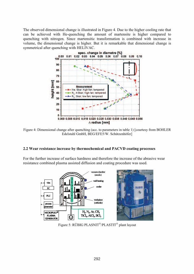
The observed dimensional change is illustrated in Figure 4. Due to the higher cooling rate that
can be achieved with He-quenching the amount of martensite is higher compared to
quenching with nitrogen. Since martensitic transformation is combined with increase in
volume, the dimensional change is higher. But it is remarkable that dimensional change is
symmetrical after quenching with HELIVAC.
Figure 4: Dimensional change after quenching (acc. to parameters in table 1) [courtesy from BOHLER
Edelstahl GmbH, BEG/EFE5/W. Schützenhöfer]
2.2 Wear resistance increase by thermochemical and PACVD coating processes
For the further increase of surface hardness and therefore the increase of the abrasive wear
resistance combined plasma assisted diffusion and coating procedure was used.
Figure 5: RÜBIG PLASNIT/PLASTIT
plant layout
workpiece
(cathodic)
workpiece
(cathodic)
workpiece
(cathodic)
wall heatingwall heatingwall heating
vacuum chamber
(anodic)
vacuum chamber
(anodic)
coolercoolercooler
H2, N2, Ar, CH4
TiCl4, AlCl3, BCl3
H2, N2, Ar, CH4
TiCl4, AlCl3, BCl3
H2, N2, Ar, CH4
TiCl4, AlCl3, BCl3
MICROPULS ®
PLASMA
GENERATOR
MICROPULS ®
PLASMA
GENERATOR
MICROPULS ®
PLASMA
GENERATOR
MICROPULS ®
PLASMA
GENERATOR
MICROPULS ®
PLASMA
GENERATOR
process
parameter
process
parameter
process
parameter
process
parameter
PLCPLCPLCPLC
PC
visu
PC
visu
PC
visu
PC
visu
292
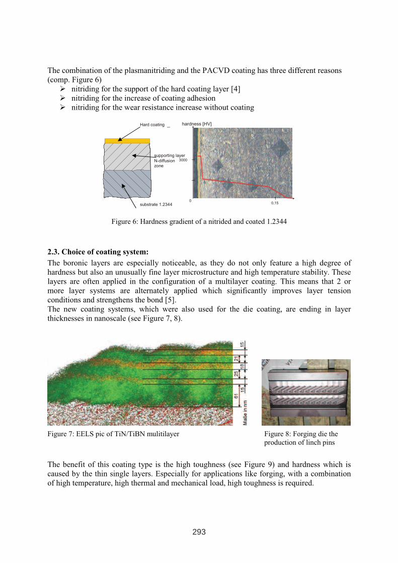
The combination of the plasmanitriding and the PACVD coating has three different reasons
(comp. Figure 6)
� nitriding for the support of the hard coating layer [4]
� nitriding for the increase of coating adhesion
� nitriding for the wear resistance increase without coating
Figure 6: Hardness gradient of a nitrided and coated 1.2344
2.3. Choice of coating system:
The boronic layers are especially noticeable, as they do not only feature a high degree of
hardness but also an unusually fine layer microstructure and high temperature stability. These
layers are often applied in the configuration of a multilayer coating. This means that 2 or
more layer systems are alternately applied which significantly improves layer tension
conditions and strengthens the bond [5].
The new coating systems, which were also used for the die coating, are ending in layer
thicknesses in nanoscale (see Figure 7, 8).
Figure 7: EELS pic of TiN/TiBN mulitilayer Figure 8: Forging die the
production of linch pins
The benefit of this coating type is the high toughness (see Figure 9) and hardness which is
caused by the thin single layers. Especially for applications like forging, with a combination
of high temperature, high thermal and mechanical load, high toughness is required.
3000
0,15
hardness [HV]
0
Hard coating
supporting layer
N-diffusionzone
substrate 1.2344
293
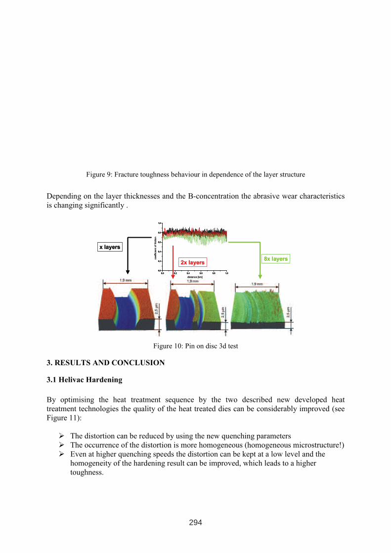
Figure 9: Fracture toughness behaviour in dependence of the layer structure
Depending on the layer thicknesses and the B-concentration the abrasive wear characteristics
is changing significantly .
0,0 0,2 0,4 0,6 0,8 1,0
0,0
0,2
0,4
0,6
0,8
1,0
coeffic
ien
toffr
ictio
n
distance [km]
x layers
2x layers8x layers
0,0 0,2 0,4 0,6 0,8 1,0
0,0
0,2
0,4
0,6
0,8
1,0
coeffic
ien
toffr
ictio
n
distance [km]
x layers
2x layers8x layers
Figure 10: Pin on disc 3d test
3. RESULTS AND CONCLUSION
3.1 Helivac Hardening
By optimising the heat treatment sequence by the two described new developed heat
treatment technologies the quality of the heat treated dies can be considerably improved (see
Figure 11):
� The distortion can be reduced by using the new quenching parameters
� The occurrence of the distortion is more homogeneous (homogeneous microstructure!)
� Even at higher quenching speeds the distortion can be kept at a low level and the
homogeneity of the hardening result can be improved, which leads to a higher
toughness.
294
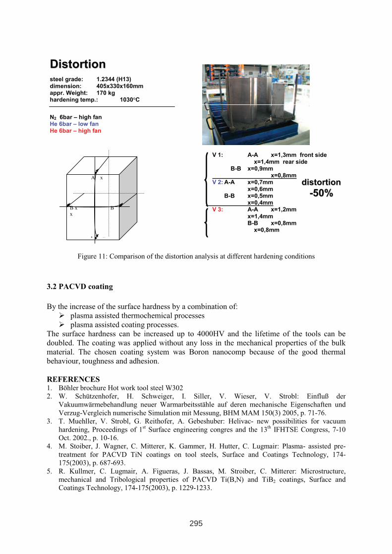
Figure 11: Comparison of the distortion analysis at different hardening conditions
3.2 PACVD coating
By the increase of the surface hardness by a combination of:
� plasma assisted thermochemical processes
� plasma assisted coating processes.
The surface hardness can be increased up to 4000HV and the lifetime of the tools can be
doubled. The coating was applied without any loss in the mechanical properties of the bulk
material. The chosen coating system was Boron nanocomp because of the good thermal
behaviour, toughness and adhesion.
REFERENCES 1. Böhler brochure Hot work tool steel W302
2. W. Schützenhofer, H. Schweiger, I. Siller, V. Wieser, V. Strobl: Einfluß der
Vakuumwärmebehandlung neuer Warmarbeitsstähle auf deren mechanische Eigenschaften und
Verzug-Vergleich numerische Simulation mit Messung, BHM MAM 150(3) 2005, p. 71-76.
3. T. Muehller, V. Strobl, G. Reithofer, A. Gebeshuber: Helivac- new possibilities for vacuum
hardening, Proceedings of 1st Surface engineering congres and the 13
th IFHTSE Congress, 7-10
Oct. 2002., p. 10-16.
4. M. Stoiber, J. Wagner, C. Mitterer, K. Gammer, H. Hutter, C. Lugmair: Plasma- assisted pre-
treatment for PACVD TiN coatings on tool steels, Surface and Coatings Technology, 174-
175(2003), p. 687-693.
5. R. Kullmer, C. Lugmair, A. Figueras, J. Bassas, M. Stroiber, C. Mitterer: Microstructure,
mechanical and Tribological properties of PACVD Ti(B,N) and TiB2 coatings, Surface and
Coatings Technology, 174-175(2003), p. 1229-1233.
DDiissttoorrttiioonn
A x
B x B
x
A x
V 1: A-A x=1,3mm front sidex=1,4mm rear side
B-B x=0,9mm x=0,8mm
V 2: A-A x=0,7mm x=0,6mm
B-B x=0,5mm x=0,4mm
V 3: A-A x=1,2mm x=1,4mm B-B x=0,8mm
x=0,8mm
steel grade: 1.2344 (H13)dimension: 405x330x160mm appr. Weight: 170 kg hardening temp.: 1030°C
N2 6bar – high fan He 6bar – low fan He 6bar – high fan
ddiissttoorrttiioonn
--5500%%
295

EFFECTS OF THERMOCHEMICAL TREATMENTS ON MARAGING
STEEL PROPERTIES F. Cajner, D. Landek, S. Šolić, H. Cajner
Faculty of Mechanical Engineering and Naval Architecture, University of Zagreb, Ivana
Lučića 1, Zagreb, Croatia
ABSTRACT
Effects of thermochemical processes carburizing, nitriding and boriding upon properties of
MARAGING steel grades have been considered. Despite certain improvements in properties
of the surface achieved, due to problems in layer quality and difficulties in dimensions control
processes carburizing, and boriding can not be recommended currently. Nitriding has proved
to be the most suitable process, and subsequent surfacing with TiN layer on the previously
nitrided substratum of MARAGING steel provided additional improvement of properties.
Key words: Steel Properties, MARAGING Steel, Thermochemical Treatment
1. INTRODUCTION
MARAGING steels, besides being used for manufacture of different structural parts, are also
used for manufacture of tools. Compared to more commonly used steels for such purposes,
MARGING steels have certain advantages, such as excellent ability for hardening, high
impact toughness, high resistance to thermal fatigue, simple heat treatment (without
protective atmosphere, without distortions) good machinability and good weldability. Despite
the listed advantages, major objections to their applications is too low resistance to wear,
particularly when tooling is exposed to more intensive wear, as it is the case with processing
of polymers containing abrasive fillers and/or reinforcements.
Thermochemical treatments can significantly improve resistance to wear of common steels.
Therefore it might be justified to try to improve wear resistance also of this class of steels
applying thermochemical treatments.
For these grades of steel reference data are recommending nitriding (nitro-carburizing) as an
appropriate process of thermochemical treatment [1-6]. Possible achievement of quality
boride layers may indicate possible application of boriding for manufacture of tools which are
exposed to harsh abrasion wear during operation. This is of particular importance, since in
the case of application of structural steels that can be successfully borided, rather soft
substratum is provided as a base for hard boride layer. In the case of tool steels, due to high
content of carbon and alloying elements, too thin and brittle layer is produced. In this report,
beside the application of nitriding (nitro-carburizing), possible use of bording and carburizing
of MARAGING steels is considered, the aim being to improve resistance to wear. Also,
effects of subsequent surfacing with TiN layer on MARAGING steel that was nitrided in
preceding step.
1 INTERNATIONAL CONFERENCE ON HEAT TREATMENT
AND SURFACE ENGINEERING OF TOOLS AND DIES
st
Pula, Croatia 08 - 11 June, 2005,
IFHTSE 2005
297
2. DESCRIPTION OF CONDUCTED RESEARCH
All research has been preformed with the 14-10-5 MARAGING steel (MARLOK C1650, [7])
having chemical composition which is given in table I.
Heat treatment of test samples has been done according to data specified in table II. Starting
approach has been to apply common processes of thermochemical treatment (nitrocarburizing,
nitriding, carburizing and boriding) using common agents and process parameters without
modification, i.e. changes of particular process that might be adjusted to MARAGING steel.
Evaluation of the effect of every thermo-chemical treatment upon the properties of
MARAGING steel has been done on all samples (of specified shape and dimensions required
for testing of each particular property) applying micrographic testing, hardness testing
(distribution of hardness in a cross-section) and tribological testing.
Results of micrographic testing and testing of hardness are presented in Figs 1 – 4.
Tribological testing included testing of resistance to abrasion, erosion and adhesion wear.
Testing has been done applying “dry sand- rubber wheel” device, using quartz sand of Ottawa
50/70 grade and load of 45 N. Results of testing are given in Fig. 5.
Same sand has been used for testing of erosion wear where impact angle of sand stream to the
sample was set at 90o. Results are presented in Fig. 6. Adhesive wear has been tested applying
hardened friction ring and load of 100 N. During this testing, friction coefficient has been
established (Fig. 7). Details of performed tribological testing has been discussed in [6].
3. ANALYSIS OF RESULTS
3.1. Effects of carburizing upon the properties of MARAGING steel
Carburizing of MARAGING steel produced following effects:
- Applying common carburizing granulate and standard process parameters (at 900oC
for 4 hours), steel sample has been carburized to a considerable depth (total depth of
carburized layer was approximately 0,8 mm) Fig 1.
- After carburizing and cooling in air, high carbon martensite (containing probably
residual austenite) of increased hardness is formed in the carburized zone, Fig. 1. After
additional ageing at 500oC/4 hours, hardness of carburized edge has been somewhat
reduced (for approximately 80 HV 1), while hardness of the core is increased, an
expected result of precipitation of intermetallic phases in Ni-martensite
- Despite only slight increase of hardness in the carburized layer, higher resistance to
abrasion wear, Fig. 5, and lower coefficient of friction have been obtained if compared
to conditions without thermo-chemical treatment or nitrided condition [5]
Despite achieved improvement against adhesive and abrasive wear, possible adverse
consequences should be mentioned, resulting from the following facts:
- During cooling from carburizing temperature, carburized martensite is formed in the
carburized layer, causing additional distortions, probably greater than in the case when
nickel-martensite is formed
- Due to increased hardness in the edge layer (approximately 700 HV 1), machining
(e.g. turning or milling) to required dimensions is not possible. Thus one of major
advantages of MARAGING steels in manufacturing of tooling is lost, i.e. “distortion-
free” thermo-chemical treatment.
298
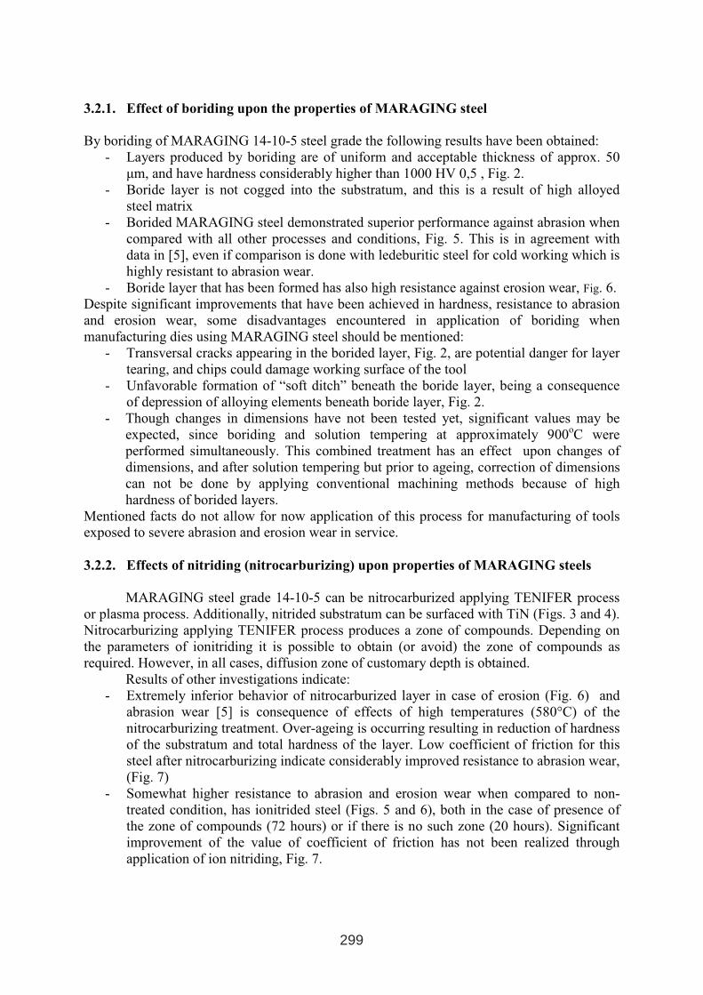
3.2.1. Effect of boriding upon the properties of MARAGING steel
By boriding of MARAGING 14-10-5 steel grade the following results have been obtained:
- Layers produced by boriding are of uniform and acceptable thickness of approx. 50
µm, and have hardness considerably higher than 1000 HV 0,5 , Fig. 2.
- Boride layer is not cogged into the substratum, and this is a result of high alloyed
steel matrix
- Borided MARAGING steel demonstrated superior performance against abrasion when
compared with all other processes and conditions, Fig. 5. This is in agreement with
data in [5], even if comparison is done with ledeburitic steel for cold working which is
highly resistant to abrasion wear.
- Boride layer that has been formed has also high resistance against erosion wear, Fig. 6.
Despite significant improvements that have been achieved in hardness, resistance to abrasion
and erosion wear, some disadvantages encountered in application of boriding when
manufacturing dies using MARAGING steel should be mentioned:
- Transversal cracks appearing in the borided layer, Fig. 2, are potential danger for layer
tearing, and chips could damage working surface of the tool
- Unfavorable formation of “soft ditch” beneath the boride layer, being a consequence
of depression of alloying elements beneath boride layer, Fig. 2.
- Though changes in dimensions have not been tested yet, significant values may be
expected, since boriding and solution tempering at approximately 900oC were
performed simultaneously. This combined treatment has an effect upon changes of
dimensions, and after solution tempering but prior to ageing, correction of dimensions
can not be done by applying conventional machining methods because of high
hardness of borided layers.
Mentioned facts do not allow for now application of this process for manufacturing of tools
exposed to severe abrasion and erosion wear in service.
3.2.2. Effects of nitriding (nitrocarburizing) upon properties of MARAGING steels
MARAGING steel grade 14-10-5 can be nitrocarburized applying TENIFER process
or plasma process. Additionally, nitrided substratum can be surfaced with TiN (Figs. 3 and 4).
Nitrocarburizing applying TENIFER process produces a zone of compounds. Depending on
the parameters of ionitriding it is possible to obtain (or avoid) the zone of compounds as
required. However, in all cases, diffusion zone of customary depth is obtained.
Results of other investigations indicate:
- Extremely inferior behavior of nitrocarburized layer in case of erosion (Fig. 6) and
abrasion wear [5] is consequence of effects of high temperatures (580°C) of the
nitrocarburizing treatment. Over-ageing is occurring resulting in reduction of hardness
of the substratum and total hardness of the layer. Low coefficient of friction for this
steel after nitrocarburizing indicate considerably improved resistance to abrasion wear,
(Fig. 7)
- Somewhat higher resistance to abrasion and erosion wear when compared to non-
treated condition, has ionitrided steel (Figs. 5 and 6), both in the case of presence of
the zone of compounds (72 hours) or if there is no such zone (20 hours). Significant
improvement of the value of coefficient of friction has not been realized through
application of ion nitriding, Fig. 7.
299
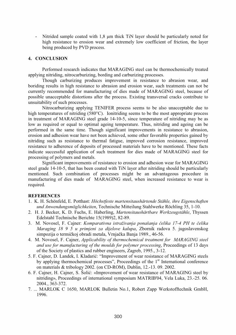
- Nitrided sample coated with 1,8 µm thick TiN layer should be particularly noted for
high resistance to erosion wear and extremely low coefficient of friction, the layer
being produced by PVD process.
4. CONCLUSION
Performed research indicates that MARAGING steel can be thermochemically treated
applying nitriding, nitrocarburizing, bording and carburizing processes.
Though carburizing produces improvement in resistance to abrasion wear, and
boriding results in high resistance to abrasion and erosion wear, such treatments can not be
currently recommended for manufacturing of dies made of MARAGING steel, because of
possible unacceptable distortions after the process. Existing transversal cracks contribute to
unsuitability of such processes.
Nitrocarburizing applying TENIFER process seems to be also unacceptable due to
high temperatures of nitriding (580°C). Ionitriding seems to be the most appropriate process
in treatment of MARAGING steel grade 14-10-5, since temperature of nitriding may be as
low as required or equal to optimal ageing temperature. Thus, nitriding and ageing can be
performed in the same time. Though significant improvements in resistance to abrasion,
erosion and adhesion wear have not been achieved, some other favorable properties gained by
nitriding such as resistance to thermal fatigue, improved corrosion resistance, improved
resistance to adherence of deposits of processed materials have to be mentioned. These facts
indicate successful application of such treatment for dies made of MARAGING steel for
processing of polymers and metals.
Significant improvements of resistance to erosion and adhesion wear for MARAGING
steel grade 14-10-5, that has been coated with TiN layer after nitriding should be particularly
mentioned. Such combination of processes might be an advantageous procedure in
manufacturing of dies made of MARAGING steel, when increased resistance to wear is
required.
REFERENCES
1. K. H. Schönfeld, E. Potthast: Höchstfeste martensitaushärtende Stähle, ihre Eigenschaften
und Anwendungsmöglichkeiten, Technische Mitteilung Stahlwerke Röchling 35, 1-10.
2. H. J. Becker, K. D. Fuchs, E. Haberling, Martensitaushärtbare Werkzeugstähle, Thyssen
Edelstahl Technische Berichte 15(1989)2, 82-89.
3. M. Novosel, F. Cajner: Komparativna istraživanja ponašanja čelika 17-4 PH te čelika
Maraging 18 9 5 u primjeni za dijelove kalupa, Zbornik radova 5. jugoslavenskog
simpozija o termičkoj obradi metala, Vrnjačka Banja 1989., 46-56.
4. M. Novosel, F. Cajner, Applicability of thermochemical treatment for MARAGING steel
and use for manufacturing of the moulds for polymer processing, Proceedings of 13 days
of the Society of plastics and rubber engineers, Zagreb, 1995., 3-12.
5. F. Cajner, D. Landek, I. Kladarić: “Improvement of wear resistance of MARAGING steels
by applying thermochemical processes”, Proceedings of the 1st International conference
on materials & tribology 2002. (on CD-ROM), Dublin, 12.-13. 09. 2002.
6. F. Cajner, H. Cajner, S. Šolić: «Improvement of wear resistance of MARAGING steel by
nitriding», Proceedings of international symposium MATRIB'04, Vela Luka, 23.-25. 06.
2004., 363-372.
7. ... MARLOK C 1650, MARLOK Bulletin No.1, Robert Zapp Werkstofftechnik GmbH,
1996.
300
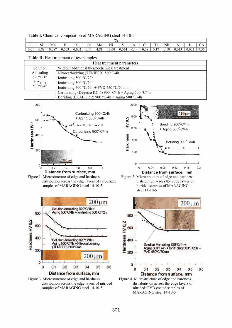
Table I. Chemical composition of MARAGING steel 14-10-5%
C Si Mn P S Cr Mo Ni V Al Cu Ti Nb N B Co 0,01 0,88 0,087 0,003 0,002 0,11 4,81 13,60 0,024 0,14 0,08 0,17 0,10 0,013 0,002 9,50
Table II. Heat treatment of test samples
Heat treatment parameters
Without additional thermochemical treatment
Nitrocarburizing (TENIFER) 580ºC/4h
Ionitriding 500 °C/72h
Ionitriding 500 °C/20h
Solution
Annealing
820ºC/1h
+ Aging
500ºC/4h Ionitriding 500 °C/20h + PVD 450 °C/70 min.
Carburizing (Degussa KG 6) 900 °C/4h + Aging 500 °C/4h -
Boriding (EKABOR 2) 900 °C/4h + Aging 500 °C/4h
0 0.2 0.4 0.6 0.8 1
Distance from surface, mm
0
200
400
600
800
Ha
rdn
es
sH
V1
Carburizing 900oC/4h
Carburizing 900oC/4h
+ Aging 500oC/4h
0 0.04 0.08 0.12 0.16 0.2
Distance from surface, mm
0
400
800
1200
1600
2000
Hard
ne
ss
HV
0.5
Boriding 900oC/4h
Boriding 900oC/4h
+ Aging 500oC/4h
Figure 1. Microstructure of edge and hardness
distribution across the edge layers of carburized
samples of MARAGING steel 14-10-5
Figure 2. Microstructure of edge and hardness
distribution across the edge layers of
borided samples of MARAGING
steel 14-10-5
Figure 3. Microstructure of edge and hardness
distribution across the edge layers of nitrided
samples of MARAGING steel 14-10-5
Figure 4. Microstructure of edge and hardness
distributi- on across the edge layers of
nitrided+PVD coated samples of
MARAGING steel 14-10-5
301
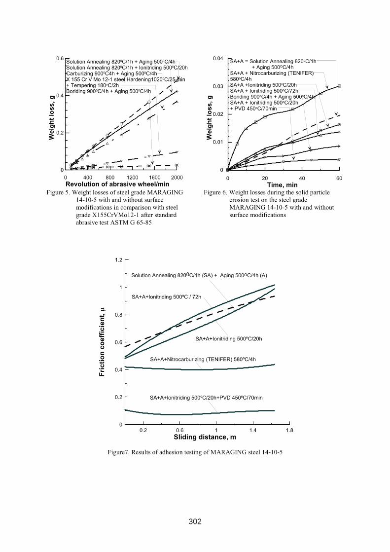
0 400 800 1200 1600 2000
Revolution of abrasive wheel/min
0
0.2
0.4
0.6
Weig
ht
loss
,g
Solution Annealing 8200C/1h + Aging 5000C/4hSolution Annealing 8200C/1h + Ionitriding 5000C/20hCarburizing 9000C4h + Aging 5000C/4hX 155 Cr V Mo 12-1 steel Hardening10200C/25 min+ Tempering 180oC/2hBoriding 9000C/4h + Aging 5000C/4h
0 20 40 60
Time, min
0
0.01
0.02
0.03
0.04
We
igh
tlo
ss
,g
SA+A = Solution Annealing 820oC/1h + Aging 500OC/4h
SA+A + Nitrocarburizing (TENIFER)580oC/4hSA+A +Ionitriding 500oC/20hSA+A + Ionitriding 500oC/72hBoriding 900oC/4h + Aging 500oC/4hSA+A + Ionitriding 500oC/20h + PVD 450oC/70min
Figure 5. Weight losses of steel grade MARAGING
14-10-5 with and without surface
modifications in comparison with steel
grade X155CrVMo12-1 after standard
abrasive test ASTM G 65-85
Figure 6. Weight losses during the solid particle
erosion test on the steel grade
MARAGING 14-10-5 with and without
surface modifications
0.2 0.6 1 1.4 1.8
Sliding distance, m
0
0.4
0.8
1.2
0.2
0.6
1
Fri
cti
on
co
eff
icie
nt,µ
Solution Annealing 8200C/1h (SA) + Aging 500oC/4h (A)
SA+A+Ionitriding 500ºC / 72h
SA+A+Ionitriding 500ºC/20h
SA+A+Nitrocarburizing (TENIFER) 580ºC/4h
SA+A+Ionitriding 500ºC/20h+PVD 450ºC/70min
Figure7. Results of adhesion testing of MARAGING steel 14-10-5
302
LASER BEAM MACHINING OF HARD METAL
H.-J. Pieper; E. Wolf; M. Krause
Otto-von-Guericke-University of Magdeburg
Institute of Manufacturing Technology and Quality Management (IFQ)
Universitätsplatz 2
39106 Magdeburg
-Germany-
ABSTRACT
In comparison to the far greater acceptance of laser beam machining, little is still known
about the course of the process. There is also a lack of reliable information on how the mate-
rial responses to the impact of the laser beam (surface damage). Currently, few scientifically
grounded, technological data are available on the removal of hard metals by using laser beams.
This study investigates the impact of laser radiation (wavelength of 1064 nm) on various hard
metal configurations. In addition to the removal behaviour, the resulting surface damage as
well as surface roughness was studied as target parameters that can be influenced.
Keywords: laser machining, hard metal, rapid tooling technology, micro engineering
technology
1. INTRODUCTION
In recent years, industry has witnessed an increasing demand of tools capable of quickly giv-
ing parts most diverse geometries. Part and parcel of this development are keywords such as
rapid prototyping or the machining of new materials which are difficult or impossible to ma-
chine with traditional processes such as milling, grinding or EDM. For these fields of applica-
tion, the innovative laser beam removal process seems to be a suitable answer 23. Advantages
of removing material using laser radiation include:
• high process flexibility and a high degree of automation based on NC-controls and
linkage to CAD-CAM process chains
• production of nearly any structure without the need to change tools or high production
costs for suitable tool electrodes, and
• touch-free and consequently force-free machining of extremely hard and non-
conducting materials.
Laser beam machining may be used, for instance, for machining fully sintered hard metals,
e.g. for cutting chip removal tracks into a fully sintered disposable cemented-carbide insert, as
is common in everyday industrial practice [1].
1 INTERNATIONAL CONFERENCE ON HEAT TREATMENT
AND SURFACE ENGINEERING OF TOOLS AND DIES
st
Pula, Croatia 08 - 11 June, 2005,
IFHTSE 2005
303
In this case, laser beam machining competes with the traditional machining processes of EDM
and grinding. However, the latter two are inferior due to their process-related shortcomings.
So far there has been a lack of reliable information on the removal behaviour of hard metals
using a pulsed Nd:YAG laser so that problems may occur with regard to attaining a repro-
ducible surface and machining quality. By applying suitable process parameters the hard
metal should, if possible, evaporate completely, and be removed from the machining zone by
the generated steam pressure. Otherwise, surface quality may deteriorate due to droplet for-
mation. Information is also sparse on removal rates and surface qualities attainable when
submitting hard metals to a pulsed laser beam machining process. Recent research performed
at the Institute of Manufacturing Technology and Quality Management at Magdeburg Univer-
sity has focused on determining optimal laser and process parameters.
One current study aims at thoroughly investigating the geometrically determined two-
dimensional machining of hard metals. As a radiation source, a cw-Q-switch-Nd:YAG laser is
employed, as is common in the majority of 3D laser micro machining concepts. In experi-
ments, the impact of influencing parameters relevant to the process is determined, such as the
light’s current intensity, repetition rate, and scanner feed velocity, on the qualitative and quan-
titative target values of surface roughness, layer removal rate, and peripheral zone impact.
One aspect of the study, which has already been completed, focused on determining techno-
logical performance characteristics for removal and roughness behaviour occurring in two-
dimensional laser beam machining processes. Comparative investigations of hard metals with
different grain diameters were performed to determine the impact of this material characteris-
tic on the machining process. In this research the mean grain diameters of tungsten carbide
were varied by using an ultra fine grain hard metal, a fine grain hard metal, and a standard
grain hard metal. In addition, it was used only pure WC-CO hard metals containing 6% of
binder metal to counteract the impact of other structural constituents and different concentra-
tions of the cobalt binder. The study also focused on changing the raw laser beam diameter
from 1.3 mm to 1.8 mm, which causes a change in the effective focus diameter. So it was pos-
sible to estimate the relationship between the effective beam surface parameter and the re-
moval rate or quality because it is highly relevant to the process, similar to the tool diameter
analogous to face milling.
2. PROCESS OVERVIEW
Laser beam machining is a well-known process, which has been studied scientifically since a
laser was first, put into practice more than 40 years ago. First, drilling with the help of laser
radiation was given priority. One of the first industrial applications of the laser technology
included the drilling of gemstones for watches in 1968, followed by the drilling of cooling
bores in turbine blades. Nowadays, laser drilling has found a variety of industrial applications
with a tendency to improve the shape of the bore or to increase the aspect relationship 5.
Since the beginning of the 1990s, laser machining has been used in a number of fields to pro-
duce dies and to structure surfaces. Figure 1 shows how to quantitatively group treatment re-
sults achieved so far with different laser sources in terms of minimum lateral structural di-
mension and geometrical accuracy. Geometrical accuracy is closely linked to the roughness,
which may be obtained 10.
304
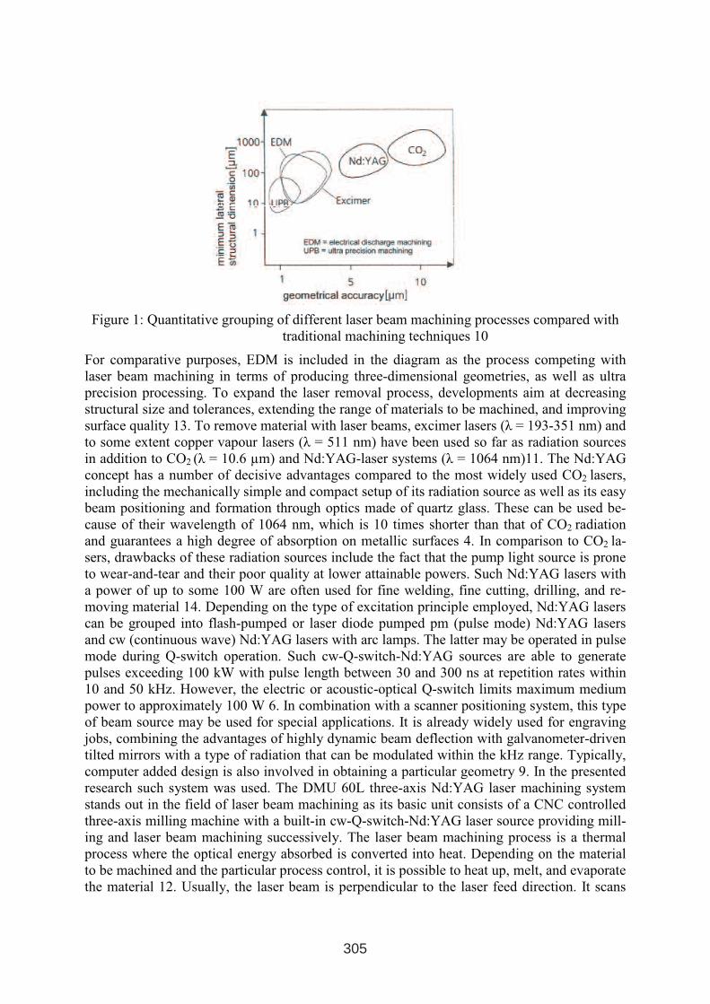
Figure 1: Quantitative grouping of different laser beam machining processes compared with
traditional machining techniques 10
For comparative purposes, EDM is included in the diagram as the process competing with
laser beam machining in terms of producing three-dimensional geometries, as well as ultra
precision processing. To expand the laser removal process, developments aim at decreasing
structural size and tolerances, extending the range of materials to be machined, and improving
surface quality 13. To remove material with laser beams, excimer lasers (λ = 193-351 nm) and
to some extent copper vapour lasers (λ = 511 nm) have been used so far as radiation sources
in addition to CO2 (λ = 10.6 µm) and Nd:YAG-laser systems (λ = 1064 nm)11. The Nd:YAG
concept has a number of decisive advantages compared to the most widely used CO2 lasers,
including the mechanically simple and compact setup of its radiation source as well as its easy
beam positioning and formation through optics made of quartz glass. These can be used be-
cause of their wavelength of 1064 nm, which is 10 times shorter than that of CO2 radiation
and guarantees a high degree of absorption on metallic surfaces 4. In comparison to CO2 la-
sers, drawbacks of these radiation sources include the fact that the pump light source is prone
to wear-and-tear and their poor quality at lower attainable powers. Such Nd:YAG lasers with
a power of up to some 100 W are often used for fine welding, fine cutting, drilling, and re-
moving material 14. Depending on the type of excitation principle employed, Nd:YAG lasers
can be grouped into flash-pumped or laser diode pumped pm (pulse mode) Nd:YAG lasers
and cw (continuous wave) Nd:YAG lasers with arc lamps. The latter may be operated in pulse
mode during Q-switch operation. Such cw-Q-switch-Nd:YAG sources are able to generate
pulses exceeding 100 kW with pulse length between 30 and 300 ns at repetition rates within
10 and 50 kHz. However, the electric or acoustic-optical Q-switch limits maximum medium
power to approximately 100 W 6. In combination with a scanner positioning system, this type
of beam source may be used for special applications. It is already widely used for engraving
jobs, combining the advantages of highly dynamic beam deflection with galvanometer-driven
tilted mirrors with a type of radiation that can be modulated within the kHz range. Typically,
computer added design is also involved in obtaining a particular geometry 9. In the presented
research such system was used. The DMU 60L three-axis Nd:YAG laser machining system
stands out in the field of laser beam machining as its basic unit consists of a CNC controlled
three-axis milling machine with a built-in cw-Q-switch-Nd:YAG laser source providing mill-
ing and laser beam machining successively. The laser beam machining process is a thermal
process where the optical energy absorbed is converted into heat. Depending on the material
to be machined and the particular process control, it is possible to heat up, melt, and evaporate
the material 12. Usually, the laser beam is perpendicular to the laser feed direction. It scans
305
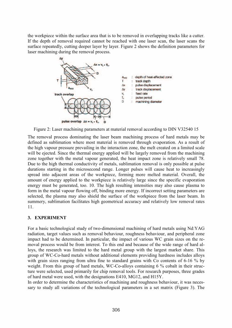
the workpiece within the surface area that is to be removed in overlapping tracks like a cutter.
If the depth of removal required cannot be reached with one laser scan, the laser scans the
surface repeatedly, cutting deeper layer by layer. Figure 2 shows the definition parameters for
laser machining during the removal process.
Figure 2: Laser machining parameters at material removal according to DIN V32540 15
The removal process dominating the laser beam machining process of hard metals may be
defined as sublimation where most material is removed through evaporation. As a result of
the high vapour pressure prevailing in the interaction zone, the melt created on a limited scale
will be ejected. Since the thermal energy applied will be largely removed from the machining
zone together with the metal vapour generated, the heat impact zone is relatively small 78.
Due to the high thermal conductivity of metals, sublimation removal is only possible at pulse
durations starting in the microsecond range. Longer pulses will cause heat to increasingly
spread into adjacent areas of the workpiece, forming more melted material. Overall, the
amount of energy applied to the workpiece is relatively large since the specific evaporation
energy must be generated, too. 10. The high resulting intensities may also cause plasma to
form in the metal vapour flowing off, binding more energy. If incorrect setting parameters are
selected, the plasma may also shield the surface of the workpiece from the laser beam. In
summery, sublimation facilitates high geometrical accuracy and relatively low removal rates
11.
3. EXPERIMENT
For a basic technological study of two-dimensional machining of hard metals using Nd:YAG
radiation, target values such as removal behaviour, roughness behaviour, and peripheral zone
impact had to be determined. In particular, the impact of various WC grain sizes on the re-
moval process would be from interest. To this end and because of the wide range of hard al-
loys, the research was limited to the hard metal group with the largest market share. This
group of WC-Co-hard metals without additional elements providing hardness includes alloys
with grain sizes ranging from ultra fine to standard grains with Co contents of 6-16 % by
weight. From this group of hard metals, WC-Co-alloys containing 6 % cobalt in their struc-
ture were selected, used primarily for chip removal tools. For research purposes, three grades
of hard metal were used, with the designations E410, MG12, and H15Y.
In order to determine the characteristics of machining and roughness behaviour, it was neces-
sary to study all variations of the technological parameters in a set matrix (Figure 3). The
306
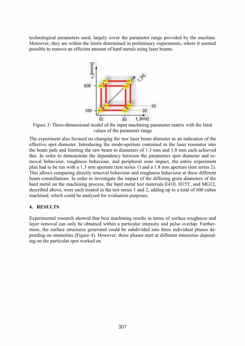
technological parameters used, largely cover the parameter range provided by the machine.
Moreover, they are within the limits determined in preliminary experiments, where it seemed
possible to remove an efficient amount of hard metals using laser beams.
Figure 3: Three-dimensional model of the input machining parameter matrix with the limit
values of the parameter range
The experiment also focused on changing the raw laser beam diameter as an indication of the
effective spot diameter. Introducing the mode-aperture contained in the laser resonator into
the beam path and limiting the raw beam to diameters of 1.3 mm and 1.8 mm each achieved
this. In order to demonstrate the dependency between the parameters spot diameter and re-
moval behaviour, roughness behaviour, and peripheral zone impact, the entire experiment
plan had to be run with a 1.3 mm aperture (test series 1) and a 1.8 mm aperture (test series 2).
This allows comparing directly removal behaviour and roughness behaviour at these different
beam constellations. In order to investigate the impact of the differing grain diameters of the
hard metal on the machining process, the hard metal test materials E410, H15Y, and MG12,
described above, were each treated in the test series 1 and 2, adding up to a total of 600 cubes
machined, which could be analysed for evaluation purposes.
4. RESULTS
Experimental research showed that best machining results in terms of surface roughness and
layer removal can only be obtained within a particular intensity and pulse overlap. Further-
more, the surface structures generated could be subdivided into three individual phases de-
pending on intensities (Figure 4). However, these phases start at different intensities depend-
ing on the particular spot worked on.
307
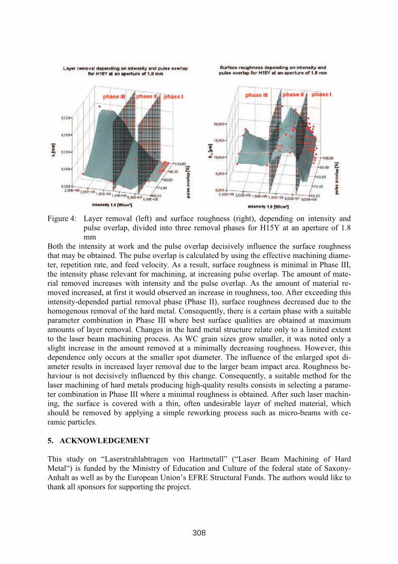
Figure 4: Layer removal (left) and surface roughness (right), depending on intensity and
pulse overlap, divided into three removal phases for H15Y at an aperture of 1.8
mm
Both the intensity at work and the pulse overlap decisively influence the surface roughness
that may be obtained. The pulse overlap is calculated by using the effective machining diame-
ter, repetition rate, and feed velocity. As a result, surface roughness is minimal in Phase III,
the intensity phase relevant for machining, at increasing pulse overlap. The amount of mate-
rial removed increases with intensity and the pulse overlap. As the amount of material re-
moved increased, at first it would observed an increase in roughness, too. After exceeding this
intensity-depended partial removal phase (Phase II), surface roughness decreased due to the
homogenous removal of the hard metal. Consequently, there is a certain phase with a suitable
parameter combination in Phase III where best surface qualities are obtained at maximum
amounts of layer removal. Changes in the hard metal structure relate only to a limited extent
to the laser beam machining process. As WC grain sizes grow smaller, it was noted only a
slight increase in the amount removed at a minimally decreasing roughness. However, this
dependence only occurs at the smaller spot diameter. The influence of the enlarged spot di-
ameter results in increased layer removal due to the larger beam impact area. Roughness be-
haviour is not decisively influenced by this change. Consequently, a suitable method for the
laser machining of hard metals producing high-quality results consists in selecting a parame-
ter combination in Phase III where a minimal roughness is obtained. After such laser machin-
ing, the surface is covered with a thin, often undesirable layer of melted material, which
should be removed by applying a simple reworking process such as micro-beams with ce-
ramic particles.
5. ACKNOWLEDGEMENT
This study on “Laserstrahlabtragen von Hartmetall” (“Laser Beam Machining of Hard
Metal“) is funded by the Ministry of Education and Culture of the federal state of Saxony-
Anhalt as well as by the European Union’s EFRE Structural Funds. The authors would like to
thank all sponsors for supporting the project.
308
REFERENCES
1. A. Kaldos, H.-J. Pieper, E. Wolf, M. Krause, “Laser machining in die making– a modern
rapid tooling process”, proceedings “Int. Conference on Advances in Materials and Proc-
essing Technologies” AMPT 2003, Dublin/Irland, 08./11.07.2003, pp. 866-869, ISBN 1-
8723-2739-7
2. F. Lierath, H.-J. Pieper, E. Wolf, M. Krause, “Laser machining – a modern procedure for
mould making”, proceedings “Int. Conference on laser technologies in welding and ma-
terials processing” LTWMP 2003, Katseveli Town, 19./23.05.2003, pp. 202-205, ISBN
966-95847-3-6
3. L. Dübner, H.-J. Pieper, E. Wolf, M. Krause “Laserstrahlabtragen ein zukunftsweisendes
Rapid Tooling Verfahren”, 4 Int. Konferenz “Moderne Technik und Technologie” 2003,
Sewastopol, in Druck
4. S. Borik, „Einfluß optischer Komponenten auf die Strahlqualität von
Hochleistungslasern“, B.G. Teubner, Stuttgart, 1993
5. H. Treiber, „Der Laser in der industriellen Fertigungstechnik“, Hoppenstedt Technik
Tabellen Verlag, Darmstadt, 1990
6. K.-M. Erhardt, A. Heine, H. Prommersberger, „Laser in der Materialbearbeitung“, Vogel
Fachbuch Verlag, Würzburg, 1993
7. G. Herziger, G. Backes, „Werkstoffbearbeitung mit Laserstrahlung“, Carl Hanser Verlag,
München/Wien, 1993
8. F. Dausinger, „Strahlwerkzeug Laser- Energiekopplung und Prozesseffektivität“, G.
Teubner, Stuttgart, 1995
9. D. Förster, W. Müller, „Laser in der Metallbearbeitung“, Fachbuchverlag Leipzig im
Carl Hanser Verlag, 2001
10. J. Freytag, „Formabtrag mit einem gepulsten Nd: YAG- Festkörperlaser in Slab-
Geometrie“, Vulkan Verlag, Essen, Dissertation, 1996
11. D. Bimberg, „Materialbearbeitung mit Lasern“, expert Verlag, Ehningen/ Böblingen,
1991
12. B. Lässiger, „Kontrollierter Formabtrag durch Sublimation mittels Laserstrahlung“,
Shaker Verlag, Dissertation, Aachen, 1995
13. H. Haferkamp, F. v. Alvensleben, H. Becker, K. Lindemann, St. Czerner, „Lasereinsatz
zur Vergütung und Reparatur im Werkzeugbau“ (Laser Zentrum Hannover), Fachbericht,
wt - Werkstatttechnik, 1989
14. M. Beck, „Verbundprojekt: Abtragen mit Laserphotonen- Laserpräzisionsbearbeitung
keramischer Hochleistungswerkstoffe: Bauteile und Werkzeuge aus Verbundwerkstoffen
und Siliziumnitrid“, Daimler Benz AG, Forschung und Technologie, Hannover, 2000
15. DIN V 32540
309

EXPERIMENTAL RESEARCH CONCERNING THE THERMAL
SHOCK BEHAVIOUR OF SOME ION NITRIDED STAINLESS STEELS
Vasile RUS, Gavril NEGREA, Horaţiu VERMEŞAN
Faculty of Materials Science and Engineering, Technical University of Cluj-Napoca, Muncii
Avenue, No. 103-105, 400641, Cluj-Napoca, România
ABSTRACT:
Due to their excellent oxidation and corrosion resistance, stainless steels are mainly used for
tools and parts that work in environments with high chemical aggressiveness. Very often,
such components are subjected not only to mechanical loads but also to thermal cycles that
generate thermal stresses, which, in many cases, are the principal cause of premature failure.
While the influence of surface modification technologies and coatings on wear, corrosion and
mechanical surface fatigue resistance has been investigated extensively, there are few studies
on their influence on thermal fatigue. The main purpose of this work is to investigate the
influence of ion nitriding on thermal shock behaviour of two stainless steel grades:
X3CrNiMo17-13-3 (austenitic) and X20Cr13 (martensitic). Samples made from the two steel
grades were first ion nitrided or and then subjected to thermal shock testing by using a home
made apparatus. The samples were first heated to the desired temperature (500o
or 600oC)
and then cooled rapidly by immersion in water. Ion nitriding was performed in dissociated
amonia and H2-N2-CH4 mixture. The sample surface was examined by optical microscopy in
order to determine the number of cycles until the formation of the first cracks and then to
determine the number of cracks length and the number of triple points after formation of a
cracks network. The study put into evidence two different types of crack initiation and crack
growth on the two steel grades. Possible mechanisms responsible for such cracking behaviour
are also proposed.
Keywords: tools, stainless steel, thermal shock, ion nitriding.
1. INTRODUCTION
Stainless steels, characterised mainly by their high oxidation and corrosion resistance and also
presenting special mechanical, physical and technological properties, represent one of the
steel categories mainly used for different pieces and tools subjected to thermal cycles [1,2,3].
The ion nitriding is one of the surface engineering technologies which allows the
improvement of wear resistance, fatigue resistance due to a favorable stress state (compresion
in the superficial layer and tension in the core), a high temperature resistance, corosion
resistance etc [4]. The exigences regarding the behaviour in exploitation of the tools are
continuosly growing so the complex mode of loading of pieces and of tools leads to a need of
ensuring a multifunctional behaviour [5].
1 INTERNATIONAL CONFERENCE ON HEAT TREATMENT
AND SURFACE ENGINEERING OF TOOLS AND DIES
st
Pula, Croatia 08 - 11 June, 2005,
IFHTSE 2005
311
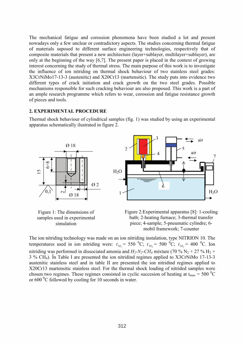
The mechanical fatigue and corossion phenomena have been studied a lot and present
nowadays only a few unclear or contradictory aspects. The studies concerning thermal fatigue
of materials suposed to different surface engineering technologies, respectively that of
composite materials that present a new architecture (layer+sublayer, multilayer+sublayer), are
only at the beginning of the way [6,7]. The present paper is placed in the context of growing
interest concerning the study of thermal stress. The main purpose of this work is to investigate
the influence of ion nitriding on thermal shock behaviour of two stainless steel grades:
X3CrNiMo17-13-3 (austenitic) and X20Cr13 (martensitic). The study puts into evidence two
different types of crack initiation and crack growth on the two steel grades. Possible
mechanisms responsible for such cracking behaviour are also proposed. This work is a part of
an ample research programme which refers to wear, corossion and fatigue resistance growth
of pieces and tools.
2. EXPERIMENTAL PROCEDURE
Thermal shock behaviour of cylindrical samples (fig. 1) was studied by using an experimental
apparatus schematically ilustrated in figure 2.
The ion nitriding technology was made on an ion nitriding instalation, type NITRION 10. The
temperatures used in ion nitriding were: 1NIt = 550
0C;
2NIt = 5000C;
3NIt = 4000C. Ion
nitriding was performed in dissociated amonia and H2-N2-CH4 mixture (70 % N2 + 27 % H2 +
3 % CH4). În Table I are presented the ion nitridind regimes applied to X3CrNiMo 17-13-3
austenitic stainless steel and in table II are presented the ion nitridind regimes applied to
X20Cr13 martensitic stainless steel. For the thermal shock loading of nitrided samples were
chosen two regimes. These regimes consisted in cyclic succesion of heating at tmax = 5000C
or 600 0C followed by cooling for 10 seconds in water.
Figure 1: The dimensions of
samples used in experimental
simulation
Figure 2:Experimental apparatus [8]: 1-cooling
bath; 2-heating furnace; 3-thermal transfer
piece; 4-sample; 5-pneumatic cylindre; 6-
mobil framework; 7-counter
H2O15
6÷
8
0,1Ø 18
Ø 18
Ø 2
2
H2O
air
air2
3
1
54
7
6H2O
312
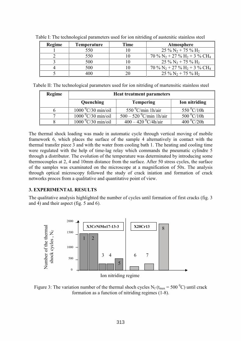
Table I: The technological parameters used for ion nitriding of austenitic stainless steel
Regime Temperature Time Atmosphere
1 550 10 25 % N2 + 75 % H2
2 550 10 70 % N2 + 27 % H2 + 3 % CH4
3 500 10 25 % N2 + 75 % H2
4 500 10 70 % N2 + 27 % H2 + 3 % CH4
5 400 20 25 % N2 + 75 % H2
Tabele II: The technological parameters used for ion nitriding of martensitic stainless steel
Heat treatment parametersRegime
Quenching Tempering Ion nitriding
6 10000C/30 min/oil 550
0C/min 1h/air 550
0C/10h
7 10000C/30 min/oil 500 – 520
0C/min 1h/air 500
0C/10h
8 10000C/30 min/oil 400 – 420
0C/4h/air 400
0C/20h
The thermal shock loading was made in automatic cycle through vertical moving of mobile
framework 6, which places the surface of the sample 4 alternatively in contact with the
thermal transfer piece 3 and with the water from cooling bath 1. The heating and cooling time
were regulated with the help of time-lag relay which commands the pneumatic cylindre 5
through a distributor. The evolution of the temperature was determinated by introducing some
thermocouples at 2, 4 and 10mm distance from the surface. After 50 stress cycles, the surface
of the samples was examinated on the microscope at a magnification of 50x. The analysis
through optical microscopy followed the study of crack iniation and formation of crack
networks proces from a qualitative and quantitative point of view.
3. EXPERIMENTAL RESULTS
The qualitative analysis highlighted the number of cycles until formation of first cracks (fig. 3
and 4) and their aspect (fig. 5 and 6).
Figure 3: The variation number of the thermal shoch cycles Nf (tmax = 500 0C) until crack
formation as a function of nitriding regimes (1-8).
Num
ber
of
the
ther
mal
shock
cycl
es,
Nf
2000
1500
1000
500
0
1 2
8X3CrNiMo17-13-3 X20Cr13
3 4
5
6 7
Ion nitriding regime
313
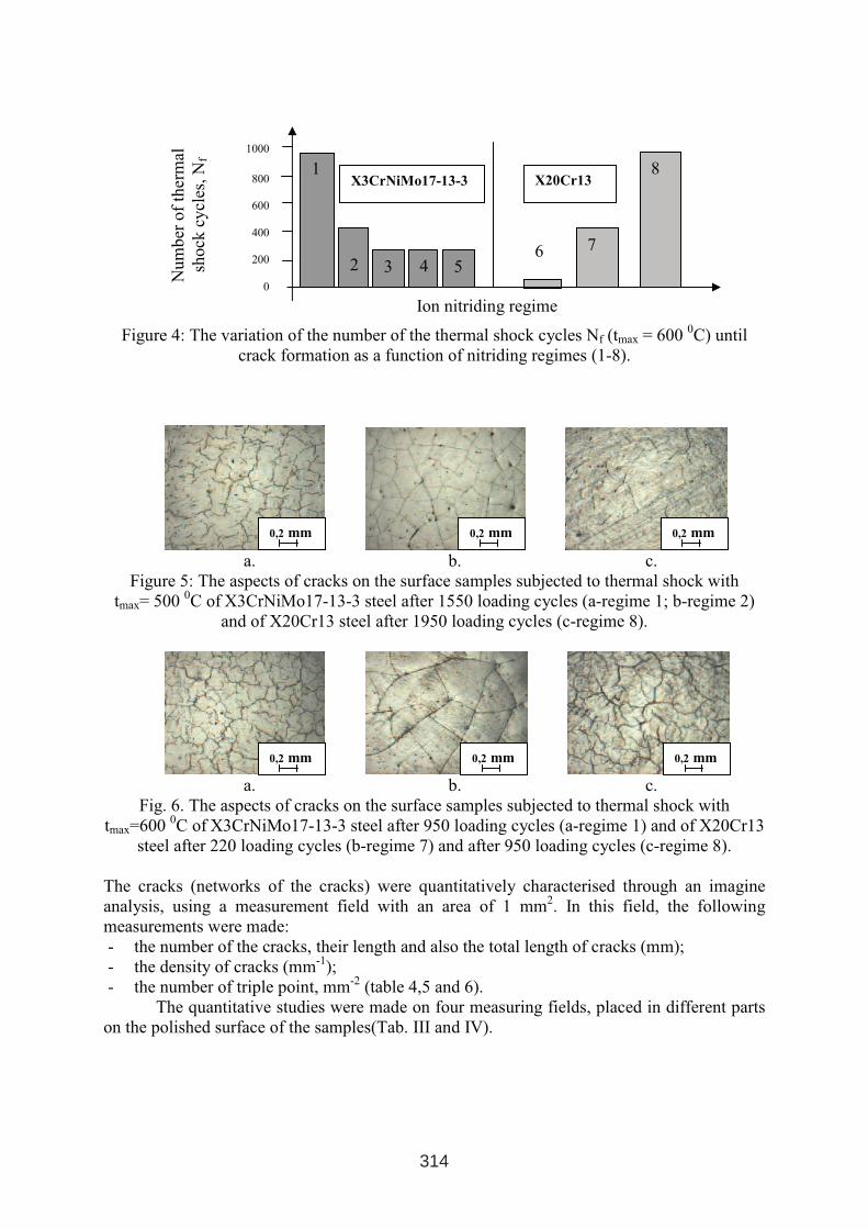
Figure 4: The variation of the number of the thermal shock cycles Nf (tmax = 600 0C) until
crack formation as a function of nitriding regimes (1-8).
a. b. c.
Figure 5: The aspects of cracks on the surface samples subjected to thermal shock with
tmax= 5000C of X3CrNiMo17-13-3 steel after 1550 loading cycles (a-regime 1; b-regime 2)
and of X20Cr13 steel after 1950 loading cycles (c-regime 8).
a. b. c.
Fig. 6. The aspects of cracks on the surface samples subjected to thermal shock with
tmax=600 0C of X3CrNiMo17-13-3 steel after 950 loading cycles (a-regime 1) and of X20Cr13
steel after 220 loading cycles (b-regime 7) and after 950 loading cycles (c-regime 8).
The cracks (networks of the cracks) were quantitatively characterised through an imagine
analysis, using a measurement field with an area of 1 mm2. In this field, the following
measurements were made:
- the number of the cracks, their length and also the total length of cracks (mm);
- the density of cracks (mm-1
);
- the number of triple point, mm-2
(table 4,5 and 6).
The quantitative studies were made on four measuring fields, placed in different parts
on the polished surface of the samples(Tab. III and IV).
Num
ber
of
ther
mal
shock
cycl
es,N
f
1000
800
600
400
200
0
1
2 5
X3CrNiMo17-13-3
3 4
8
7
X20Cr13
Ion nitriding regime
6
0,2 mm 0,2 mm 0,2 mm
0,2 mm 0,2 mm 0,2 mm
314
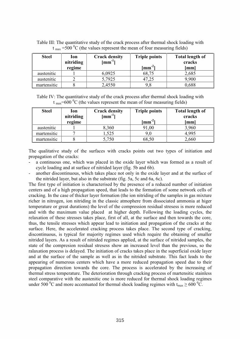
Table III: The quantitative study of the crack process after thermal shock loading with
t max =500 0C (the values represent the mean of four measuring fields)
Steel Ion
nitriding
regime
Crack density
[mm-1
]
Triple points
[mm-2
]
Total length of
cracks
[mm]
austenitic 1 6,0925 68,75 2,685
austenitic 2 5,7925 47,25 9,900
martensitic 8 2,4550 9,8 0,688
Table IV: The quantitative study of the crack process after thermal shock loading with
t max=600 0C (the values represent the mean of four measuring fields)
Steel Ion
nitriding
regime
Crack density
[mm-1
]
Triple points
[mm-2
]
Total length of
cracks
[mm]
austenitic 1 8,360 91,00 3,960
martensitic 7 1,525 9,0 4,995
martensitic 8 5,750 68,50 2,660
The qualitative study of the surfaces with cracks points out two types of initiation and
propagation of the cracks:
- a continuous one, which was placed in the oxide layer which was formed as a result of
cycle loading and at surface of nitrided layer (fig. 5b and 6b).
- another discontinuous, which takes place not only in the oxide layer and at the surface of
the nitrided layer, but also in the substrate (fig. 5a, 5c and 6a, 6c).
The first type of initiation is characterised by the presence of a reduced number of initiation
centers and of a high propagation speed, that leads to the formation of some network cells of
cracking. In the case of thicker layer formation (the ion nitriding of the samples in gas mixture
richer in nitrogen, ion nitriding in the classic atmophere from dissociated ammonia at higer
temperature or great durations) the level of the compression residual stresess is more reduced
and with the maximum value placed at higher depth. Following the loading cycles, the
relaxation of these stresses takes place, first of all, at the surface and then towards the core,
thus, the tensile stresses which appear lead to initiation and propagation of the cracks at the
surface. Here, the accelerated cracking process takes place. The second type of cracking,
discontinuous, is typical for majority regimes used which require the obtaining of smaller
nitrided layers. As a result of nitrided regimes applied, at the surface of nitrided samples, the
state of the compresion residual stresess show an increased level than the previous, so the
ralaxation process is delayed. The initiation of cracks takes place in the superficial oxide layer
and at the surface of the sample as well as in the nitrided substrate. This fact leads to the
appearing of numerous centers which have a more reduced propagation speed due to their
propagation direction towards the core. The process is accelerated by the increasing of
thermal stress temperature. The deterioration through cracking process of martensitic stainless
steel comparative with the austenitic one is more reduced for thermal shock loading regimes
under 500 0C and more accentuated for thermal shock loading regimes with tmax ≥ 600
0C.
315
4. CONCLUSIONS
The qualitative and quantitative studiy of cracking proces to X3CrNiMo 17-13-3 and
X20Cr13 steels has shown the following significant aspects:
1. Thermal shock resistance is diminuated whith the increasing of the maximum temperature
of the loading cycle.
2. The ion nitriding improves this resistance by inducing compresion residual stresses at the
surface but at the increasing of the temperature at 6000C and over, beside the structural
changes, a premature relaxing of these stresses takes place which facilitates the crack
initiation process. In the circumstance of the loading conditions studied, for ion nitrided
samples is established a retarding of the craking process comparative to unnitrided
samples.
3. Higher resistance at thermal shock of ion nitrided martensitic stainless steel comparative
to the austenitic one , in the case of reduced maximum temperature of the thermal cycle,
tmax = 5000C is emphasized by a lower density of the cracks DF = 21,6 mm
-1, of the
reduced number of crack initiation, of a lower triple point number but also of the total
length of the cracks LfT = 0,688 mm, that is lower. This allows the use of ion nitrided
martensitic stainless steels at thermocycle loaded tools execution at temperatures up to
5000C.
REFERENCES
1. Armas-Alvarez, I., Armas, F.A., Petersen, C., Termal fatigue of a 12% cromium
martensitic stainlles steel, In: Fatigue and Fracture of Engineering Materials and
Structures Ltd. Vol.17, No.6, p.671-681, 1994, Great Britain.
2. Lemoine, P., Marini, B., Meny, L., Etude de la fatigue thermique superficielle d’un acier inoxydable austenitique, Fatigue a haute température, Journées internationales de
printemps, Paris, 9-11 Juni 1986.
3. Marchand, F., Utilisation des alliages réfractaires dans les outillages de traitements
thermiques, In Traitement Thermique, No 323/2000, p. 22-24.
4. Rus, V., Vermeşan, G., Thermal shock behaviour of ion nitrided stainless steels, In:
Proceedings, Second International Conference On Materials And Manufacturig
Technologies, MATEHN ’98, Cluj-Napoca, 10-13 September 1998, Volume 2, p. 871-
876.
5. Rus, V., Thermal shock behaviour of ion nitrided stainless steels, Thesis, Technical
University of Cluj-Napoca, 5 May 2004.
6. V. Rus , G. Negrea, B.M. Rus, D. Porcar, C. Coroş, Thermal shock behaviour of
martensitic stainless steel , In: Heat Treatments and Surface Engineering, Bucharest vol.
V, Nr. 3-4/2004, p. 4-10, ISSN 1221-5678.
7. Rus, V., Vermeşan, G., Negrea, G., Porcar, D.,. Study on thermal shock behaviour of ion
nitrided X3CrNiMo17-13-3 stainless steel, In: Proceedings, International Conference on
Advanced Materials and Technologies ROMAT 2004, 21 – 22 octomber 2004, Bucharest,
p. 225 – 234, ISBN 973-718-081-X.
8. Rus, V., Negrea, G., Porcar, D., Experimental apparatus for the study of thermal shock,
In: Proceedings, BRAMAT 2005, International Conference on Materials Science and
Engineering, Braşov, 24-26 February 2005, ISBN 973-635-454-7.
316
NITRIDING WITHOUT WHITE LAYER WITH CONTINUOUSLY
CHANGE THE NITRIDING POTENTIAL DURING PROCESS
Jerzy Michalski, Aleksander Nakonieczny, Jan Tacikowski, Piotr Wach
Institute of Precision Mechanics, 3 Duchnicka Str. 01-796, Warsaw, Poland
ABSTRACT
In the paper is presented results of nitriding of chromium-molibdenium-aluminum steel
without white layer and are described mathematical relationship for continuously change the
nitriding potential during process. The equilibrium system which describes the correlation
between the conventionally defined nitriding potential (Np) and the nitriding temperature on
the one hand and the phases α, γ’ and ε in equilibrium on the other hand, developed originally
by E. Lehrer, does not take into account changes taking place with time. It is advisable to
reduce the value of the nitriding potential as time of process proceeds, in order not to exceed
the border concentration of nitrogen in the diffusion zone, which would cause the formation
of the ε or γ‘- phases on the steel surface. To this date there is a lack of equilibrium systems
between the gas phase and the external concentration of nitrogen in the layer for alloy steels,
depending on temperature and time. The determination of the essential parameters is
accomplished experimentally for given steel grades and processing conditions. With an
increase of the potential there is a rise of the zone of internal nitriding (diffusion zone). The
highest rise occurs when the nitriding potential KN of the atmosphere corresponds to the upper
limit of nitrogen concentration in the α zone. Further increase of the nitriding potential causes
the formation on the steel surface of the ε phase and with the rise in the thickness of the εzone, there comes about a reduction in the rate of growth of the zone with the α structure.
Keywords: Nitriding potential, compound layer, diffusion zone, nitriding without white layer
1 INTERNATIONAL CONFERENCE ON HEAT TREATMENT
AND SURFACE ENGINEERING OF TOOLS AND DIES
st
Pula, Croatia 08 - 11 June, 2005,
IFHTSE 2005
317
1. INTRODUCTION
The equilibrium system which describes the correlation between the conventionally defined
nitriding potential (Np) and the nitriding temperature on the one hand and the phases α, γ’ and
ε in equilibrium on the other hand, developed originally by E. Lehrera, does not take into
account changes taking place with time. T. Bell, V. Korotchenko and S.P. Evans [1]
determined the dependence of potential on nitriding process time for chromium -
molybdenum steels (0.35 – 0.45 % C; 0.9 – 1.5 % Cr; 0.2 – 0.4 % Mo). According to these
authors, it is advisable to reduce the value of the nitriding potential as time of process
proceeds, in order not to exceed the border concentration of nitrogen in the diffusion zone,
which would cause the formation of the ε or γ‘ phases on the steel surface (Fig. 1). To this
date there is a lack of equilibrium systems between the gas phase and the external
concentration of nitrogen in the layer for alloy steels, depending on temperature and time. The
determination of the essential parameters is accomplished experimentally for given steel
grades and processing conditions. With an increase of the potential there is a rise of the zone
of internal nitriding (diffusion zone). Ts highest rise occurs when the nitriding potential KN of
the atmosphere corresponds to the upper limit of nitrogen concentration in the α zone. Further
increase of the nitriding potential causes the formation on the steel surface of the ε phase and
with the rise in the thickness of the ε zone, there comes about a reduction in the rate of growth
of the zone with the α structure [2]. If the intent of the process is to obtain a maximum
thickness of the diffusion case, the potential should be controlled in such a way that it does
not exceed the border value. By running the process in such a way we can achieve maximum
nitriding kinetics, as well as avoid the formation on the surface of a compound layer of
nitrides (or carbonitrides) of iron.
2. METHOD ADOPTED
For the expression given by Bell (Fig.1) we determined an approximation function Np=f(t) in
the following form (Logistic Model):
( )
)exp(1 tcb
atN p ⋅−⋅+
=(1)
a= 0,1966375 b=-0,9,9309867 c=0,01699909 t = 0h –72h
Changing the potential according to correlation (1) (Fig.1) we can form, on 38HMJ (135M)
steel, a nitrided case without the surface compound layer, at 515 oC.
In stable processing conditions (T = const.) the potential may be varied by changes of flow
rate of the ingoing NH3/NH3diss. In our investigations we forced the changes of potential by
changes in the composition of the ingoing NH3/NH3diss atmosphere. The equilibrium volume
fraction of ammonia in the NH3/NH3diss atmosphere, corresponding to a potential value, is
described by the expression (Logistic Model):
( )
)exp(13
tcb
atNH
⋅−⋅+
=
(2)
Taking advantage of the properties of the Logistic Model function we may write:
( )
( )tcNH
NHNH
NHtNH
t
tendt
endtgr
⋅−⋅−
+
=
=
==
=
exp1)0(
3
)0(
3
)(
3
)(
33
(3)
0.1967801)(
3 ===endtNHa
318
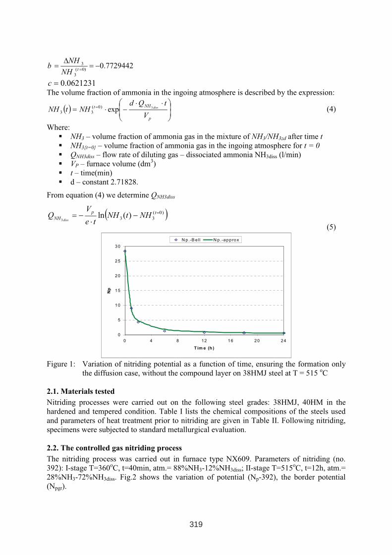
0.77294420)(
3
3 −=∆
==tNH
NHb
0.0621231=cThe volume fraction of ammonia in the ingoing atmosphere is described by the expression:
( )
⋅⋅−⋅=
=
p
NHt
V
tQdNHtNH diss3exp)0(
33(4)
Where:
� NH3 – volume fraction of ammonia gas in the mixture of NH3/NH3zd after time t
� NH3{t=0} – volume fraction of ammonia gas in the ingoing atmosphere for t = 0
� QNH3diss – flow rate of diluting gas – dissociated ammonia NH3diss (l/min)
� VP – furnace volume (dm3)
� t – time(min)
� d – constant 2.71828.
From equation (4) we determine QNH3diss
( ))0(
33 )(ln3
=−⋅
−= tp
NH NHtNHte
VQ
diss
(5)
0
5
10
15
20
25
30
0 4 8 12 16 20 24
T im e (h )
Np
N p.-B e ll N p .-approx
Figure 1: Variation of nitriding potential as a function of time, ensuring the formation only
the diffusion case, without the compound layer on 38HMJ steel at T = 515 oC
2.1. Materials tested
Nitriding processes were carried out on the following steel grades: 38HMJ, 40HM in the
hardened and tempered condition. Table I lists the chemical compositions of the steels used
and parameters of heat treatment prior to nitriding are given in Table II. Following nitriding,
specimens were subjected to standard metallurgical evaluation.
2.2. The controlled gas nitriding process
The nitriding process was carried out in furnace type NX609. Parameters of nitriding (no.
392): I-stage T=360oC, t=40min, atm.= 88%NH3-12%NH3diss; II-stage T=515
oC, t=12h, atm.=
28%NH3-72%NH3diss. Fig.2 shows the variation of potential (Np-392), the border potential
(Npgr).
319
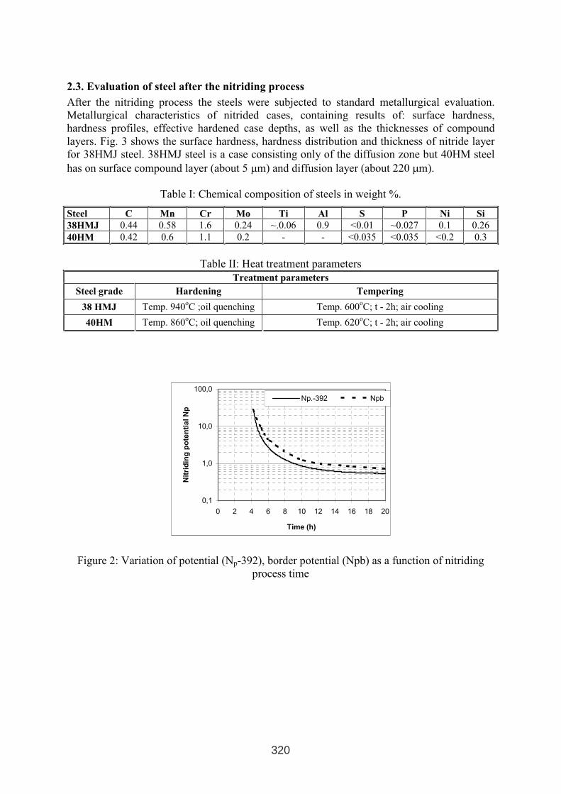
2.3. Evaluation of steel after the nitriding process
After the nitriding process the steels were subjected to standard metallurgical evaluation.
Metallurgical characteristics of nitrided cases, containing results of: surface hardness,
hardness profiles, effective hardened case depths, as well as the thicknesses of compound
layers. Fig. 3 shows the surface hardness, hardness distribution and thickness of nitride layer
for 38HMJ steel. 38HMJ steel is a case consisting only of the diffusion zone but 40HM steel
has on surface compound layer (about 5 µm) and diffusion layer (about 220 µm).
Table I: Chemical composition of steels in weight %.
Steel C Mn Cr Mo Ti Al S P Ni Si
38HMJ 0.44 0.58 1.6 0.24 ~.0.06 0.9 <0.01 ~0.027 0.1 0.26
40HM 0.42 0.6 1.1 0.2 - - <0.035 <0.035 <0.2 0.3
Table II: Heat treatment parameters
Treatment parameters
Steel grade Hardening Tempering
38 HMJ Temp. 940oC ;oil quenching Temp. 600
oC; t - 2h; air cooling
40HM Temp. 860oC; oil quenching Temp. 620
oC; t - 2h; air cooling
0,1
1,0
10,0
100,0
0 2 4 6 8 10 12 14 16 18 20
Time (h)
Nit
rid
ing
po
ten
tia
lN
p
Np.-392 Npb
320
Figure 2: Variation of potential (Np-392), border potential (Npb) as a function of nitriding
process time
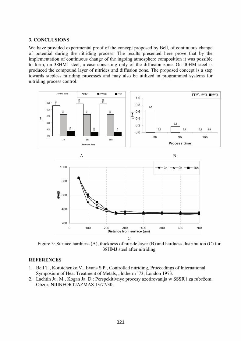
3. CONCLUSIONS
We have provided experimental proof of the concept proposed by Bell, of continuous change
of potential during the nitriding process. The results presented here prove that by the
implementation of continuous change of the ingoing atmosphere composition it was possible
to form, on 38HMJ steel, a case consisting only of the diffusion zone. On 40HM steel is
produced the compound layer of nitrides and diffusion zone. The proposed concept is a step
towards stepless nitriding processes and may also be utilized in programmed systems for
nitriding process control.
38HMJ steel
1103
1159
1159
851
851
851
356
330
330
200
400
600
800
1000
1200
3h 9h 16h
Process time
HV
HV1 HVmax HVr
0,7
0,2
0,00,0 0,0 0,0
0,0
0,2
0,4
0,6
0,8
1,0
3h 9h 16h
Process time
g(u
m)
WL avg. avg.
A B
200
400
600
800
1000
0 100 200 300 400 500 600 700Distance from surface (um)
HV
05
3h 9h 16h
C
Figure 3: Surface hardness (A), thickness of nitride layer (B) and hardness distribution (C) for
38HMJ steel after nitriding
REFERENCES
1. Bell T., Korotchenko V., Evans S.P., Controlled nitriding, Proceedings of International
Symposium of Heat Treatment of Metals, „Intherm ’73, London 1973.
2. Lachtin Ju. M., Kogan Ja. D.: Perspekitivnye procesy azotirovanija w SSSR i za rubežom.
Obzor, NIIINFORTJAZMAS 13/77/30.
321

NEW TECHNOLOGY MO PVD-ARC MULTILAYER
PRODUCING PLASMA ATMOSPHERE OF Al(CH3)3 PRECURSOR
Marek Betiuk1, Kryspin Burdyński
1, Hartmut Baum
3, Aleksander Nakonieczny
1, Andrzej
Przywóski1, Marek Szudrowicz
2
1Institute of Precision Mechanics, Duchnicka 3, 01-796 Warsaw, Poland
e-mail: [email protected], [email protected] i PS, ul.Okuniewska 1, 05-070 Sulejówek, Poland
3Mining Academy, Gustav-Zeuner Str. 5, 09599 Freiberg, Germany
ABSTRACT
Among new technologies applied to obtaining of surface layers from gaseous phase especially
remarkable is PVD (Physical Vapour Deposition) method in which one of the substrate is
vapour. Actually exist many modifications of PVD methods. In their especially interested are
this, in which were used a plasma for layers deposition, for example PA PVD (Plasma
Assisted PVD) method. In technologies PA PVD the kind and the way of supplying substrates
of chemical reaction into the plasma area and the method of producing plasma play a general
role. Modern industrial tribology coatings are built from nitrides and carbonitrides phases of
such metals as: Ti, Cr, Al and Nb. They can work in the environment of wear and corrosion
influences end has high hardness in the range of 2500-6000 HV0.02. Such coatings
demonstrate also structural and phase stability in temperatures even above 750 °C.
For many years metalorganic precursor have been used in CVD techniques. The presence of
metalorganic precursors lead to decrease process temperature and make possibility to obtain
coating with diversified chemical composition. In this paper will be present a possibility of
using metalorganic compounds in PA PVD method. On this investigations we used
trimethyloaluminium (TMA) - Al(CH3)3. TMA is the one of the most widely used aluminium
precursor in MO CVD.
Recently we observed a distinct progress in surface treatments related first of all to connection
of difference technologies, for example: galvanic with PVD, so-called duplex processes. The
objective of this paper is to determinate the mechanical properties of layers produced on
aluminium alloy surfaces during the galvanic and MOPA PVD-Arc process.
Keyords: PVD, MO PVD-arc, metalorganic precursors, trimethylaluminium (TMA), duplex
processes, TiAlC
1 INTERNATIONAL CONFERENCE ON HEAT TREATMENT
AND SURFACE ENGINEERING OF TOOLS AND DIES
st
Pula, Croatia 08 - 11 June, 2005,
IFHTSE 2005
323
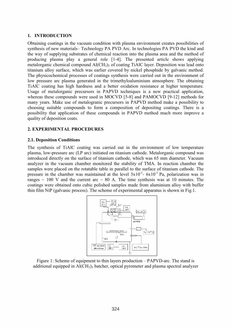
1. INTRODUCTION
Obtaining coatings in the vacuum condition with plasma environment creates possibilities of
synthesis of new materials– Technology PA PVD Arc. In technologies PA PVD the kind and
the way of supplying substrates of chemical reaction into the plasma area and the method of
producing plasma play a general role [1-4]. The presented article shows applying
metalorganic chemical compound Al(CH3)3 of coating TiAlC layer. Deposition was lead onto
titanium alloy surface, which was earlier covered by nickel phosphide by galvanic method.
The physicochemical processes of coatings synthesis were carried out in the environment of
low pressure arc plasma generated in the trimethyloaluminium atmosphere. The obtaining
TiAlC coating has high hardness and a better oxidation resistance at higher temperature.
Usage of metalorganic precursors in PAPVD techniques is a new practical application,
whereas these compounds were used in MOCVD [5-8] and PAMOCVD [9-12] methods for
many years. Make use of metalogranic precursors in PAPVD method make a possibility to
choosing suitable compounds to form a composition of depositing coatings. There is a
possibility that application of these compounds in PAPVD method much more improve a
quality of deposition coats.
2. EXPERIMENTAL PROCEDURES
2.1. Deposition Conditions
The synthesis of TiAlC coating was carried out in the environment of low temperature
plasma, low-pressure arc (LP arc) initiated on titanium cathode. Metalorganic compound was
introduced directly on the surface of titanium cathode, which was 65 mm diameter. Vacuum
analyzer in the vacuum chamber monitored the stability of TMA. In reaction chamber the
samples were placed on the rotatable table in parallel to the surface of titanium cathode. The
pressure in the chamber was maintained at the level 3x10⁻¹
- 6x10⁻¹
Pa, polarization was in
ranges ~ 100 V and the current arc ~ 80 A. The time synthesis was at 10 minutes. The
coatings were obtained onto cubic polished samples made from aluminium alloy with buffer
thin film NiP (galvanic process). The scheme of experimental apparatus is shown in Fig.1.
Figure 1: Scheme of equipment to thin layers production – PAPVD-arc. The stand is
additional equipped in Al(CH3)3 batcher, optical pyrometer and plasma spectral analyzer
324
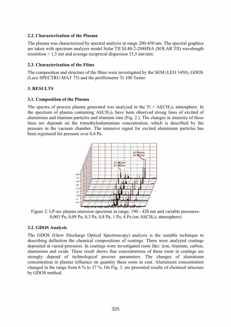
2.2. Characterization of the Plasma
The plasma was characterized by spectral analysis in range 200-450 nm. The spectral graphics
are taken with spectrum analyzer model Solar TII SL40-2-2048ISA (SOLAR TII) wavelength
resolution < 1,5 nm and average reciprocal dispersion 33,5 nm/mm.
2.3. Characterization of the Films
The composition and structure of the films were investigated by the SEM (LEO 1450), GDOS
(Leco SPECTRU-MAT 75) and the profilometer Tr 100 Tester.
3. RESULTS
3.1. Composition of the Plasma
The spectra of process plasma generated was analyzed in the Ti + Al(CH3)3 atmosphere. In
the spectrum of plasma containing Al(CH3)3 have been observed strong lines of excited of
aluminium and titanium particles and titanium ions (Fig. 2.). The changes in intensity of these
lines are depends on the trimethyloaluminium concentration, which is described by the
pressure in the vacuum chamber. The intensive signal for excited aluminium particles has
been registered for pressure over 0,4 Pa.
Figure 2: LP-arc plasma emission spectrum in range; 190 - 420 nm and variable pressures-
0,003 Pa, 0,09 Pa, 0,3 Pa, 0,8 Pa, 1 Pa, 4 Pa (on Al(CH3)3 atmosphere)
3.2. GDOS Analysis
The GDOS (Glow Discharge Optical Spectroscopy) analysis is the suitable technique to
describing definition the chemical compositions of coatings. There were analyzed coatings
deposited at varied pressures. In coatings were investigated roots like: iron, titanium, carbon,
aluminium and oxide. These result shows that concentrations of these roots in coatings are
strongly depend of technological process parameters. The changes of aluminium
concentration in plasma influence on quantity these roots in coat. Aluminium concentration
changed in the range from 6 % to 37 %. On Fig. 3. are presented results of chemical structure
by GDOS method.
325
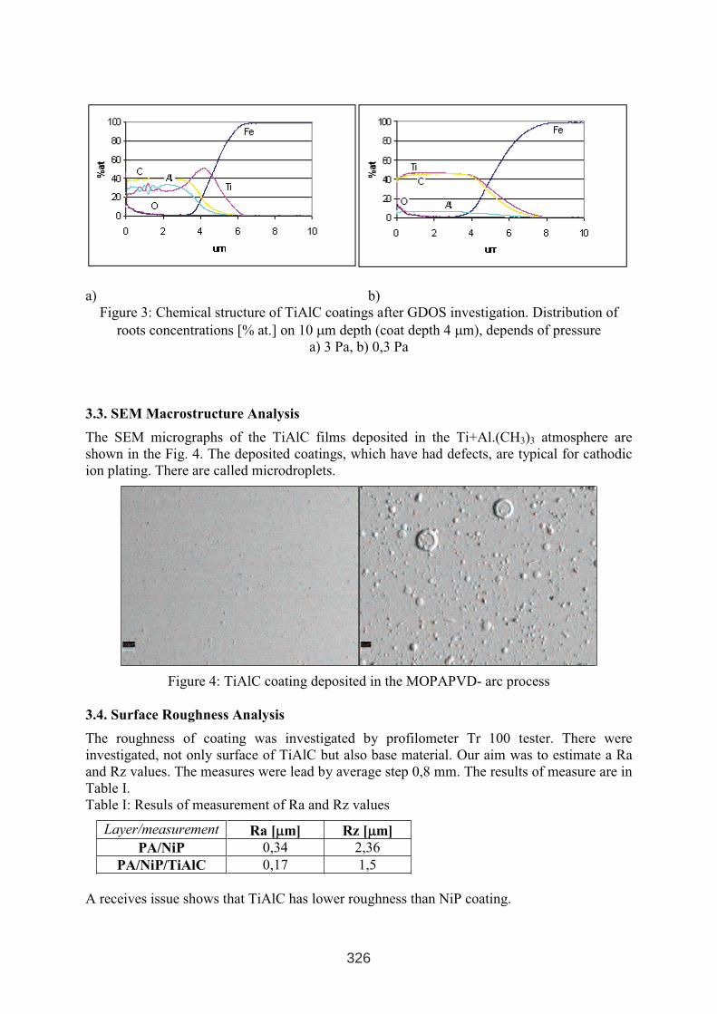
a) b)
Figure 3: Chemical structure of TiAlC coatings after GDOS investigation. Distribution of
roots concentrations [% at.] on 10 µm depth (coat depth 4 µm), depends of pressure
a) 3 Pa, b) 0,3 Pa
3.3. SEM Macrostructure Analysis
The SEM micrographs of the TiAlC films deposited in the Ti+Al.(CH3)3 atmosphere are
shown in the Fig. 4. The deposited coatings, which have had defects, are typical for cathodic
ion plating. There are called microdroplets.
Figure 4: TiAlC coating deposited in the MOPAPVD- arc process
3.4. Surface Roughness Analysis
The roughness of coating was investigated by profilometer Tr 100 tester. There were
investigated, not only surface of TiAlC but also base material. Our aim was to estimate a Ra
and Rz values. The measures were lead by average step 0,8 mm. The results of measure are in
Table I.
Table I: Resuls of measurement of Ra and Rz values
Layer/measurement Ra [µµm] Rz [µµm]
PA/NiP 0,34 2,36
PA/NiP/TiAlC 0,17 1,5
A receives issue shows that TiAlC has lower roughness than NiP coating.
326
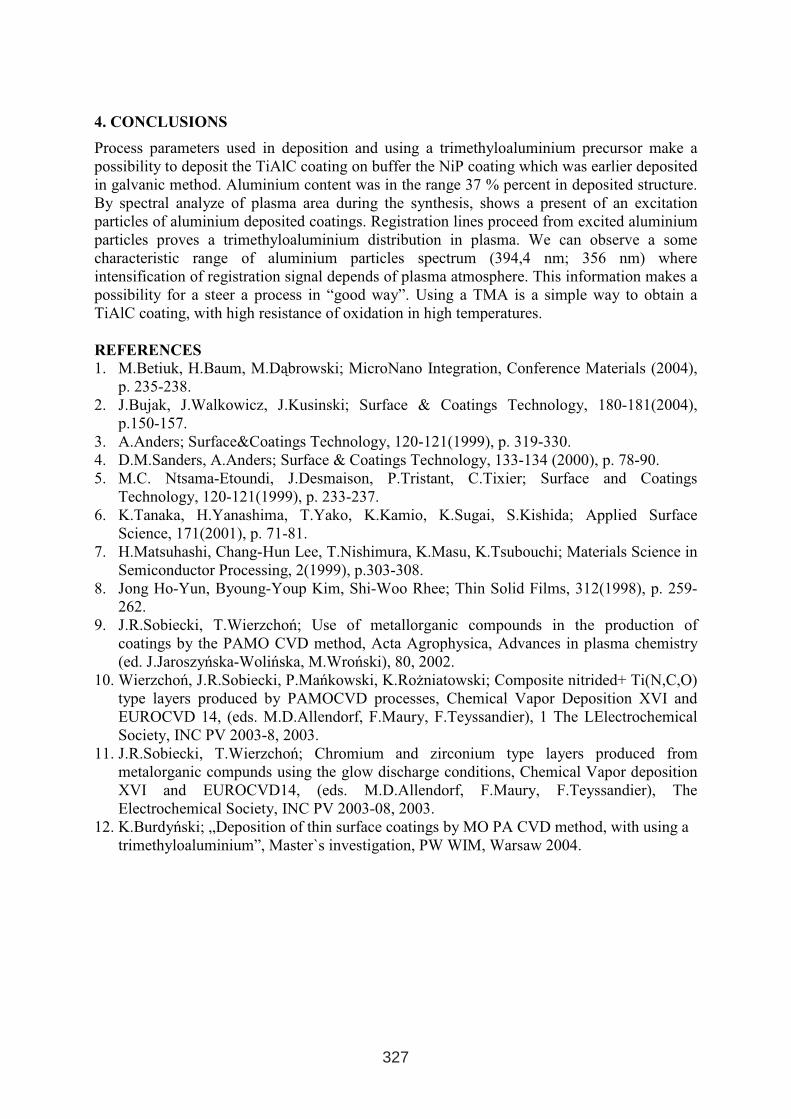
4. CONCLUSIONS
Process parameters used in deposition and using a trimethyloaluminium precursor make a
possibility to deposit the TiAlC coating on buffer the NiP coating which was earlier deposited
in galvanic method. Aluminium content was in the range 37 % percent in deposited structure.
By spectral analyze of plasma area during the synthesis, shows a present of an excitation
particles of aluminium deposited coatings. Registration lines proceed from excited aluminium
particles proves a trimethyloaluminium distribution in plasma. We can observe a some
characteristic range of aluminium particles spectrum (394,4 nm; 356 nm) where
intensification of registration signal depends of plasma atmosphere. This information makes a
possibility for a steer a process in “good way”. Using a TMA is a simple way to obtain a
TiAlC coating, with high resistance of oxidation in high temperatures.
REFERENCES
1. M.Betiuk, H.Baum, M.Dąbrowski; MicroNano Integration, Conference Materials (2004),
p. 235-238.
2. J.Bujak, J.Walkowicz, J.Kusinski; Surface & Coatings Technology, 180-181(2004),
p.150-157.
3. A.Anders; Surface&Coatings Technology, 120-121(1999), p. 319-330.
4. D.M.Sanders, A.Anders; Surface & Coatings Technology, 133-134 (2000), p. 78-90.
5. M.C. Ntsama-Etoundi, J.Desmaison, P.Tristant, C.Tixier; Surface and Coatings
Technology, 120-121(1999), p. 233-237.
6. K.Tanaka, H.Yanashima, T.Yako, K.Kamio, K.Sugai, S.Kishida; Applied Surface
Science, 171(2001), p. 71-81.
7. H.Matsuhashi, Chang-Hun Lee, T.Nishimura, K.Masu, K.Tsubouchi; Materials Science in
Semiconductor Processing, 2(1999), p.303-308.
8. Jong Ho-Yun, Byoung-Youp Kim, Shi-Woo Rhee; Thin Solid Films, 312(1998), p. 259-
262.
9. J.R.Sobiecki, T.Wierzchoń; Use of metallorganic compounds in the production of
coatings by the PAMO CVD method, Acta Agrophysica, Advances in plasma chemistry
(ed. J.Jaroszyńska-Wolińska, M.Wroński), 80, 2002.
10. Wierzchoń, J.R.Sobiecki, P.Mańkowski, K.Rożniatowski; Composite nitrided+ Ti(N,C,O)
type layers produced by PAMOCVD processes, Chemical Vapor Deposition XVI and
EUROCVD 14, (eds. M.D.Allendorf, F.Maury, F.Teyssandier), 1 The LElectrochemical
Society, INC PV 2003-8, 2003.
11. J.R.Sobiecki, T.Wierzchoń; Chromium and zirconium type layers produced from
metalorganic compunds using the glow discharge conditions, Chemical Vapor deposition
XVI and EUROCVD14, (eds. M.D.Allendorf, F.Maury, F.Teyssandier), The
Electrochemical Society, INC PV 2003-08, 2003.
12. K.Burdyński; „Deposition of thin surface coatings by MO PA CVD method, with using a
trimethyloaluminium”, Master`s investigation, PW WIM, Warsaw 2004.
327

ABRASION RESISTANCE OF THERMAL SPRAYED LAYERS
Krešimir Grilec, Suzana Jakovljević, Vera Rede
Faculty of Mechanical Engineering and Naval Architecture
University of Zagreb
Ivana Lučića 5, 10000 Zagreb
Croatia
ABSTRACT
The paper analyses abrasion resistance of five kinds of thermal sprayed layers: Tungtec
10112, Cobaltec 10092, Grit Alloy 10011, Borotec 10009 and Eutalloy 10224. Layers were
deposited on the substrate of a stainless steel (X22CrMoV121). Wear resistance was tested by
ASTM G 65-94 and differences between properties of different kinds of layers were analyzed.
Short description of thermal spraying, metallographic analysis and hardness of layers are also
presented.
Key words: wear, abrasion, thermal spraying
1. INTRODUCTION
Thermal spraying is the most versatile process of deposition of coating materials. During this
process the coating material is fed to a heating zone where it becomes molten and then is
propelled to the pre-heated substrate. Coating material can be supplied in the form of rod,
wire or powder. The distance from the spraying gun to the substrate is in the range of 0,15 to
0,3 metre. The molten particles accelerated towards the substrate are cooled to a semi molten
condition. They splatter on the substrate surface and are instantly bonded primarily by
mechanical interlocking, [1].
There are a number of techniques used to melt and propel the coating material and most
commonly applied are:
− Flame spraying
− Plasma spraying
− Detonation-gun spraying
− Electric arc spraying
In this research, the coatings have been made by flame spraying and different coating
materials have been supplied in the form of powder. Dublin Institute of technology produced
samples of coating which were tested in this work. Flame spraying utilizes the flame
produced from combustion gases to melt the coating material. Coating material is fed at a
controlled rate into the flame where it melts. The flame temperature is in the range of 3000 to
3500 °C. Compressed air is fed through the annulus around the outside of the nozzle and
accelerates the molten or semi molten particles onto the substrate.
1 INTERNATIONAL CONFERENCE ON HEAT TREATMENT
AND SURFACE ENGINEERING OF TOOLS AND DIES
st
Pula, Croatia 08 - 11 June, 2005,
IFHTSE 2005
329
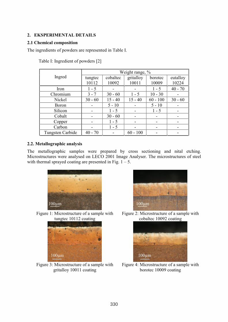
2. EKSPERIMENTAL DETAILS
2.1 Chemical composition
The ingredients of powders are represented in Table I.
Table I: Ingredient of powders [2]
Weight range, %Ingred tungtec
10112
cobaltec
10092
gritalloy
10011
borotec
10009
eutalloy
10224
Iron 1 - 5 - - 1 - 5 40 - 70
Chromium 3 - 7 30 - 60 1 - 5 10 - 30 -
Nickel 30 - 60 15 - 40 15 - 40 60 - 100 30 - 60
Boron - 5 - 10 - 5 - 10 -
Silicon - 1 - 5 - 1 - 5 -
Cobalt - 30 - 60 - - -
Copper - 1 - 5 - - -
Carbon - 1 - 5 - - -
Tungsten Carbide 40 - 70 - 60 - 100 - -
2.2. Metallographic analysis
The metallographic samples were prepared by cross sectioning and nital etching.
Microstructures were analysed on LECO 2001 Image Analyser. The microstructures of steel
with thermal sprayed coating are presented in Fig. 1 – 5.
Figure 1: Microstructure of a sample with
tungtec 10112 coating
Figure 2: Microstructure of a sample with
cobaltec 10092 coating
Figure 3: Microstructure of a sample with
gritalloy 10011 coating
Figure 4: Microstructure of a sample with
borotec 10009 coating
100µm100µm
100µm100µm
330
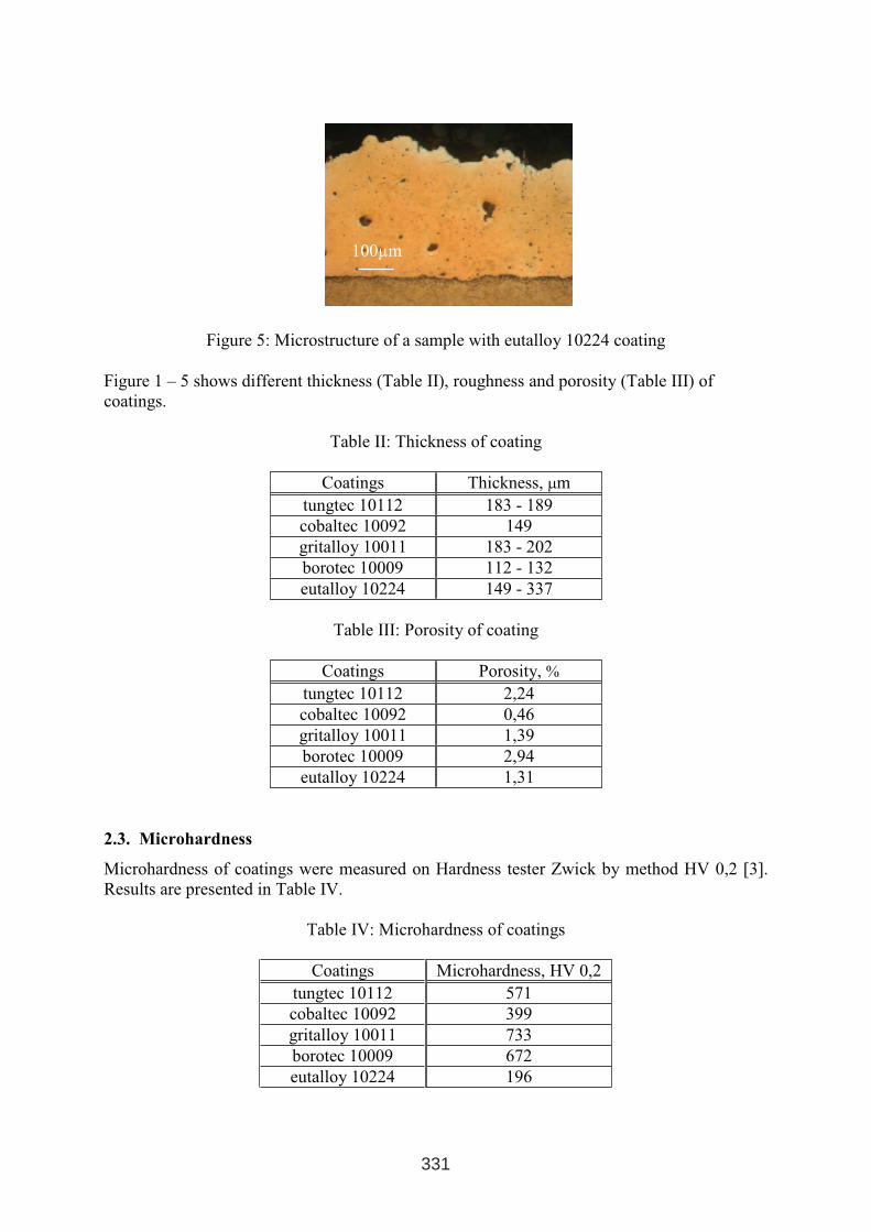
Figure 5: Microstructure of a sample with eutalloy 10224 coating
Figure 1 – 5 shows different thickness (Table II), roughness and porosity (Table III) of
coatings.
Table II: Thickness of coating
Coatings Thickness, µm
tungtec 10112 183 - 189
cobaltec 10092 149
gritalloy 10011 183 - 202
borotec 10009 112 - 132
eutalloy 10224 149 - 337
Table III: Porosity of coating
Coatings Porosity, %
tungtec 10112 2,24
cobaltec 10092 0,46
gritalloy 10011 1,39
borotec 10009 2,94
eutalloy 10224 1,31
2.3. Microhardness
Microhardness of coatings were measured on Hardness tester Zwick by method HV 0,2 [3].
Results are presented in Table IV.
Table IV: Microhardness of coatings
Coatings Microhardness, HV 0,2
tungtec 10112 571
cobaltec 10092 399
gritalloy 10011 733
borotec 10009 672
eutalloy 10224 196
100µm
331
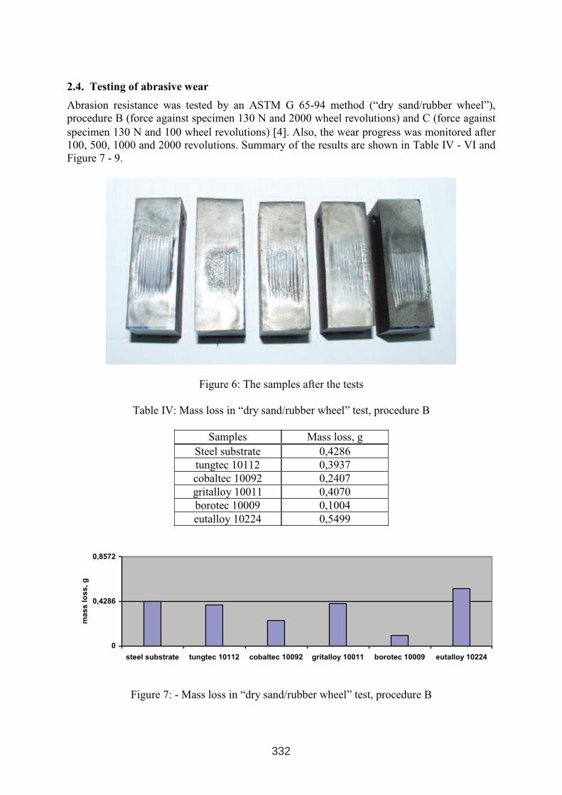
2.4. Testing of abrasive wear
Abrasion resistance was tested by an ASTM G 65-94 method (“dry sand/rubber wheel”),
procedure B (force against specimen 130 N and 2000 wheel revolutions) and C (force against
specimen 130 N and 100 wheel revolutions) [4]. Also, the wear progress was monitored after
100, 500, 1000 and 2000 revolutions. Summary of the results are shown in Table IV - VI and
Figure 7 - 9.
Figure 6: The samples after the tests
Table IV: Mass loss in “dry sand/rubber wheel” test, procedure B
Samples Mass loss, g
Steel substrate 0,4286
tungtec 10112 0,3937
cobaltec 10092 0,2407
gritalloy 10011 0,4070
borotec 10009 0,1004
eutalloy 10224 0,5499
0
0,4286
0,8572
steel substrate tungtec 10112 cobaltec 10092 gritalloy 10011 borotec 10009 eutalloy 10224
ma
ss
los
s,
g
Figure 7: - Mass loss in “dry sand/rubber wheel” test, procedure B
332
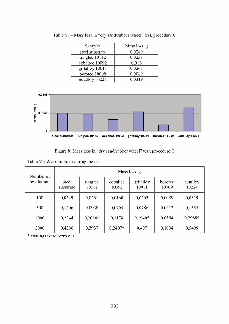
Table V: – Mass loss in “dry sand/rubber wheel” test, procedure C
Samples Mass loss, g
steel substrate 0,0249
tungtec 10112 0,0231
cobaltec 10092 0,016
gritalloy 10011 0,0263
borotec 10009 0,0089
eutalloy 10224 0,0319
0
0,0249
0,0498
steel substrate tungtec 10112 cobaltec 10092 gritalloy 10011 borotec 10009 eutalloy 10224
ma
ss
los
s,
g
Figure 8: Mass loss in “dry sand/rubber wheel” test, procedure C
Table VI: Wear progress during the test
Mass loss, gNumber of
revolutions Steel
substrate
tungtec
10112
cobaltec
10092
gritalloy
10011
borotec
10009
eutalloy
10224
100 0,0249 0,0231 0,0160 0,0263 0,0089 0,0319
500 0,1206 0,0938 0,0705 0,0786 0,0313 0,1555
1000 0,2244 0,2016* 0,1178 0,1940* 0,0554 0,2988*
2000 0,4286 0,3937 0,2407* 0,407 0,1004 0,5499
* coatings were worn out
333
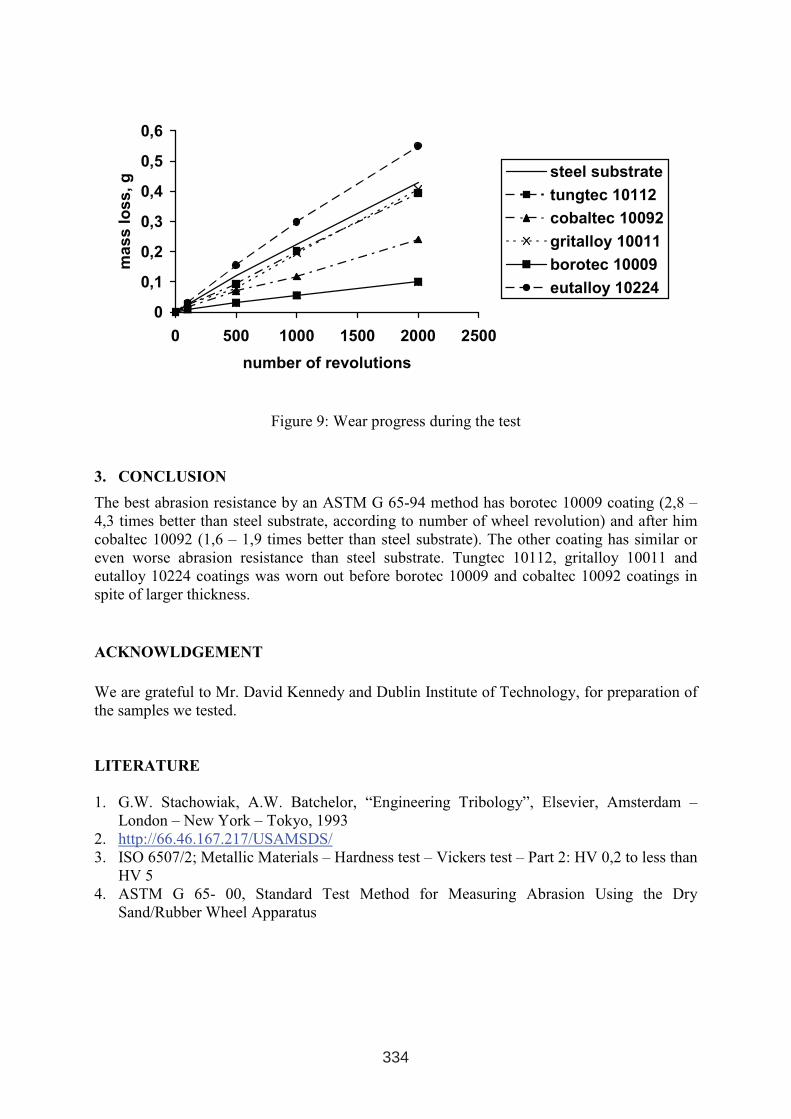
0
0,1
0,2
0,3
0,4
0,5
0,6
0 500 1000 1500 2000 2500
number of revolutions
ma
ss
los
s,
g steel substrate
tungtec 10112
cobaltec 10092
gritalloy 10011
borotec 10009
eutalloy 10224
Figure 9: Wear progress during the test
3. CONCLUSION
The best abrasion resistance by an ASTM G 65-94 method has borotec 10009 coating (2,8 –
4,3 times better than steel substrate, according to number of wheel revolution) and after him
cobaltec 10092 (1,6 – 1,9 times better than steel substrate). The other coating has similar or
even worse abrasion resistance than steel substrate. Tungtec 10112, gritalloy 10011 and
eutalloy 10224 coatings was worn out before borotec 10009 and cobaltec 10092 coatings in
spite of larger thickness.
ACKNOWLDGEMENT
We are grateful to Mr. David Kennedy and Dublin Institute of Technology, for preparation of
the samples we tested.
LITERATURE
1. G.W. Stachowiak, A.W. Batchelor, “Engineering Tribology”, Elsevier, Amsterdam –
London – New York – Tokyo, 1993
2. http://66.46.167.217/USAMSDS/
3. ISO 6507/2; Metallic Materials – Hardness test – Vickers test – Part 2: HV 0,2 to less than
HV 5
4. ASTM G 65- 00, Standard Test Method for Measuring Abrasion Using the Dry
Sand/Rubber Wheel Apparatus
334
INFLUENCE ON THE PARAMETERS OF PLASMA SPAYING
PROCESS AT THERMAL FATIGUE OF THERMAL BARRIER
COATING - ZrO2MgO
Kakaš. D1., Mrdak M.
2, Kolumbić Z.
3, Krumes D
3.
1University of Novi Sad, Faculty for Technical Science, Trg D. Obradovica 6, SiCG
2Moma Stanojlović, Zemun, SiCG
3University of Osijek, Faculty of Mechanical Engineering, Slavonski Brod, Croatia
APSTRACT
In this paper some of results related to investigation thermal barrier coatings ZrO2MgO-
NiCrAlCoY2O3 are presented. TBC was deposited by plasma spaying technology with
varying some parameters. The firs parameter was rate of deposition, from 250 to 500 mm/s.
The second parameter was number of passing, from 10 to 20. The third parameter was the
temperature of substrate. After deposition the adhesion and hardness of surface were tested.
Structure of the cross section was investigated by light microscopy and SEM. Some
quantitative analyses of the composition of surface layers were also provided. Thermo
isolation properties and resistance to fatigue were tested at 1200 ºC.
Keywors: plasma spraying, thermal barrier, ZrO2MgO, NiCrAlCoY2O3
1. INTRODUCTION
Thermal barrier coatings (TBC) produced by plasma spraying technology were developed to
protect blades of gas turbine, parts of airplane jet, diesel motors etc. [1]. Some properties of
TBC made them promising materials for application in permanent moulds for casting. High
thermal isolation property could be used to control the rate of cooling for every part of cast
and at the same time the structure, residual stresses and mechanical properties. It is very
important to reach the long life for TBC respecting the fact that permanent moulds have to
endure hundred thousand castings. The durability of TBC is dependent of composition,
porosity, residual stresses, adhesion, thickness etc.[2]. These properties are closely connected
with parameters of deposition, so optimization of deposition could significantly improve the
exploitation life of TBC coatings [3]. TBC consist at least of two different layers. The first
metal sub layer has to solve the problem of adhesion, prevent interface diffusion, increase
corrosion resistance and decrease residual stresses pick. The second ceramic sub layer has to
solve the problem of thermal insulation, decrease erosion effects, improve corrosion
resistance etc. The choice of metal sub layer is strongly connected with choice of ceramic
outer layer respecting mechanical, thermal and physical properties [4]. In this paper the
influence of new generation of metal layer NiCrAlY2O3 on behaviour of thermal barrier with
ZrO2MgO ceramic layer in thermo cyclic condition was investigated.
1 INTERNATIONAL CONFERENCE ON HEAT TREATMENT
AND SURFACE ENGINEERING OF TOOLS AND DIES
st
Pula, Croatia 08 - 11 June, 2005,
IFHTSE 2005
335
Yttrium oxide Y2O3 is well known as a stabilizer of ceramic ZrO2 layer, but in our case this
oxide was used for deposition of the metal sub layer. It was supposed that this combination
could improve the connection between metal and ceramic layer. This hypothesis was analyzed
in some previous work [5] and the results were promising. The aim of this paper is to
investigate the connection between parameters of deposition process and exploitation
properties of our combination for TBC– metal NiCrAlY2O3 and ceramic ZrO2MgO respecting
that the coating has to work in severe thermo cyclic regime.
2. EXPERIMENTAL
Composite powder with improved property compared to previous generation of metal powder
type MeCrAlY was used for deposition of metal layer. The properties are given at Table I.
Outer ceramic layer was produced by using relatively well known powder based on zirconium
oxide with 25% magnesium oxide. This type of ceramic layer possesses great thermal
isolation properties, as well as resistance to high temperature erosion, corrosion and resistance
to aggression of hot molten metals with lower melting temperature.
Table I: The properties metal powder type MeCrAlY
NiCrAlCoY2O3 ZrO2MgO
Composition Cr 17.5%;Al 5.5%; Co 2.5%;
Y2O3 0.5%; Ni - rest to 100%
Zr2O3 75%; MgO 25%
Temperature of
melting 1400°C 2140°C
Granulation 45 – 150 µm 10 – 53 µm
Samples for testing were produced from material AMS5504 according to PWA standard
recommendation with dimension 70x20x1,5 mm. Micro hardness was measured by HV0.1 at
cross section at different points – in the middle of layer and also at the right and left side of
the sample. For every point the average value of five measuring was given. Adhesion of TBC
coating was measured by testing the tensile strength of samples with dimension ∅25x50 mm.
Two samples, one with TBC layer was connected with ultra glue. Testing was done at room
temperature with the rate of increase the tension – 1 cm per minute.
Deposition of TBC was done on samples that were previously blasted with electrocorund
powder granulations from 0.7 to 1.5 mm. in order to increase adhesion. Plasma gun SG-100
was used for deposition the TBC layer with gas Ar-He with power 40 KW. Parameters for
deposition of metal sub layer were: current 900 A; voltage 38 V; primary gas flow Ar
47l/min; secondary gas flow He 32 l/min; carrier gas flow Ar 5 l/min; distance 115 mm.
Thickness of metal layer was 0.07 to 0.1 mm produced by single pass of plasma gun with
speed 250 mm/s. Ceramic layer was produced using next parameters: current 900 A; voltage
38 V; primary gas flow Ar 47l/min; secondary gas flow He 13 l/min; carrier gas flow Ar 7
l/min; distance 100 mm. Thickness of ceramic layer was 0.5 to 0.55 mm produced by 10 or 20
pass of plasma gun with speed 250 mm/s or 500 mm/s.
Two groups of samples were produced. Samples with deposition at room temperature are
marked with I and samples produced with preheating at range 160 – 180 °C are marked with
II. Samples marked with I1 and II1 were produced with speed of plasma gun passing 250
mm/s and 10 pass. Samples I2 and II2 were produced with 20 pass of plasma gun and speed
500 mm/s.
336
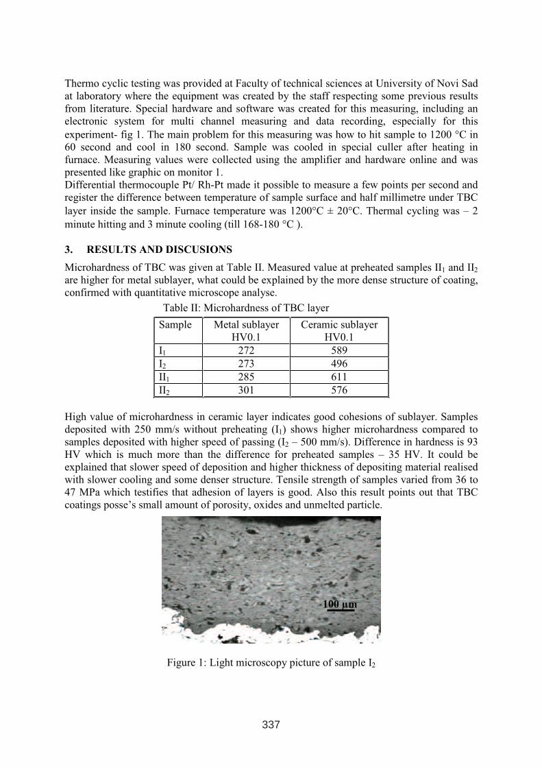
Thermo cyclic testing was provided at Faculty of technical sciences at University of Novi Sad
at laboratory where the equipment was created by the staff respecting some previous results
from literature. Special hardware and software was created for this measuring, including an
electronic system for multi channel measuring and data recording, especially for this
experiment- fig 1. The main problem for this measuring was how to hit sample to 1200 °C in
60 second and cool in 180 second. Sample was cooled in special culler after heating in
furnace. Measuring values were collected using the amplifier and hardware online and was
presented like graphic on monitor 1.
Differential thermocouple Pt/ Rh-Pt made it possible to measure a few points per second and
register the difference between temperature of sample surface and half millimetre under TBC
layer inside the sample. Furnace temperature was 1200°C ± 20°C. Thermal cycling was – 2
minute hitting and 3 minute cooling (till 168-180 °C ).
3. RESULTS AND DISCUSIONS
Microhardness of TBC was given at Table II. Measured value at preheated samples II1 and II2
are higher for metal sublayer, what could be explained by the more dense structure of coating,
confirmed with quantitative microscope analyse.
Table II: Microhardness of TBC layer
Sample Metal sublayer
HV0.1
Ceramic sublayer
HV0.1
I1 272 589
I2 273 496
II1 285 611
II2 301 576
High value of microhardness in ceramic layer indicates good cohesions of sublayer. Samples
deposited with 250 mm/s without preheating (I1) shows higher microhardness compared to
samples deposited with higher speed of passing (I2 – 500 mm/s). Difference in hardness is 93
HV which is much more than the difference for preheated samples – 35 HV. It could be
explained that slower speed of deposition and higher thickness of depositing material realised
with slower cooling and some denser structure. Tensile strength of samples varied from 36 to
47 MPa which testifies that adhesion of layers is good. Also this result points out that TBC
coatings posse’s small amount of porosity, oxides and unmelted particle.
Figure 1: Light microscopy picture of sample I2
100 µm
337
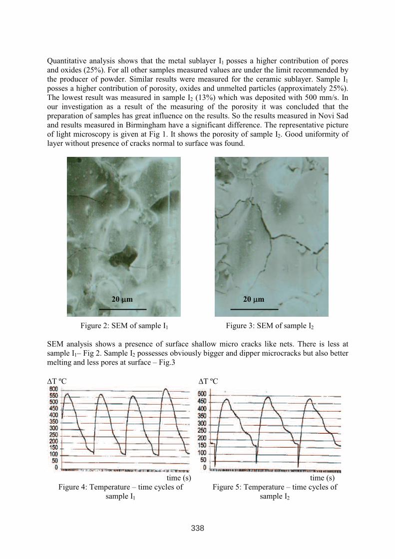
Quantitative analysis shows that the metal sublayer I1 posses a higher contribution of pores
and oxides (25%). For all other samples measured values are under the limit recommended by
the producer of powder. Similar results were measured for the ceramic sublayer. Sample I1
posses a higher contribution of porosity, oxides and unmelted particles (approximately 25%).
The lowest result was measured in sample I2 (13%) which was deposited with 500 mm/s. In
our investigation as a result of the measuring of the porosity it was concluded that the
preparation of samples has great influence on the results. So the results measured in Novi Sad
and results measured in Birmingham have a significant difference. The representative picture
of light microscopy is given at Fig 1. It shows the porosity of sample I2. Good uniformity of
layer without presence of cracks normal to surface was found.
Figure 2: SEM of sample I1 Figure 3: SEM of sample I2
SEM analysis shows a presence of surface shallow micro cracks like nets. There is less at
sample I1– Fig 2. Sample I2 possesses obviously bigger and dipper microcracks but also better
melting and less pores at surface – Fig.3
∆T ºC ∆T ºC
time (s) time (s)
Figure 4: Temperature – time cycles of
sample I1
Figure 5: Temperature – time cycles of
sample I2
20 µµm 20 µµm
338
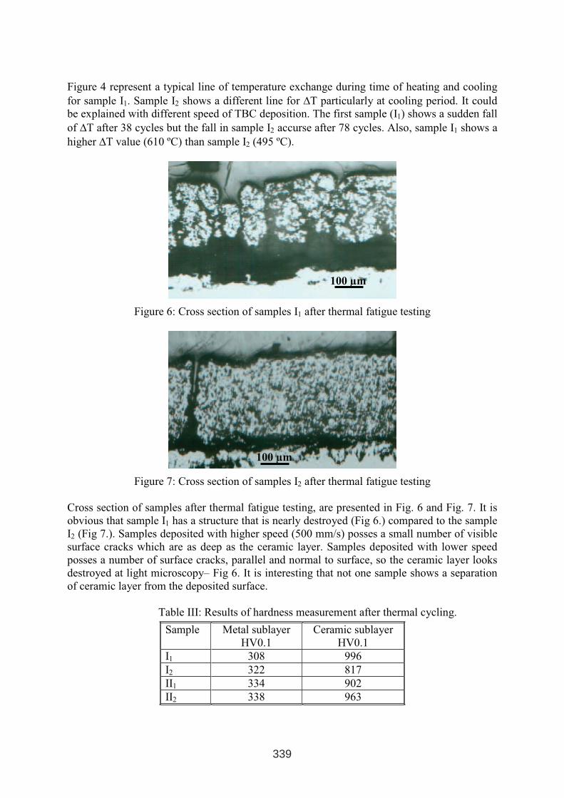
Figure 4 represent a typical line of temperature exchange during time of heating and cooling
for sample I1. Sample I2 shows a different line for ∆T particularly at cooling period. It could
be explained with different speed of TBC deposition. The first sample (I1) shows a sudden fall
of ∆T after 38 cycles but the fall in sample I2 accurse after 78 cycles. Also, sample I1 shows a
higher ∆T value (610 ºC) than sample I2 (495 ºC).
Figure 6: Cross section of samples I1 after thermal fatigue testing
Figure 7: Cross section of samples I2 after thermal fatigue testing
Cross section of samples after thermal fatigue testing, are presented in Fig. 6 and Fig. 7. It is
obvious that sample I1 has a structure that is nearly destroyed (Fig 6.) compared to the sample
I2 (Fig 7.). Samples deposited with higher speed (500 mm/s) posses a small number of visible
surface cracks which are as deep as the ceramic layer. Samples deposited with lower speed
posses a number of surface cracks, parallel and normal to surface, so the ceramic layer looks
destroyed at light microscopy– Fig 6. It is interesting that not one sample shows a separation
of ceramic layer from the deposited surface.
Table III: Results of hardness measurement after thermal cycling.
Sample Metal sublayer
HV0.1
Ceramic sublayer
HV0.1
I1 308 996
I2 322 817
II1 334 902
II2 338 963
100 µm
100 µm
339
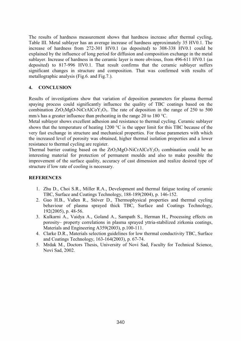
The results of hardness measurement shows that hardness increase after thermal cycling,
Table III. Metal sublayer has an average increase of hardness approximately 35 HV0.1. The
increase of hardness from 272-301 HV0.1 (as deposited) to 308-338 HV0.1 could be
explained by the influence of long period for diffusion and composition exchange in the metal
sublayer. Increase of hardness in the ceramic layer is more obvious, from 496-611 HV0.1 (as
deposited) to 817-996 HV0.1. That result confirms that the ceramic sublayer suffers
significant changes in structure and composition. That was confirmed with results of
metallographic analysis (Fig.6. and Fig.7.).
4. CONCLUSION
Results of investigations show that variation of deposition parameters for plasma thermal
spaying process could significantly influence the quality of TBC coatings based on the
combination ZrO2MgO-NiCrAlCoY2O3. The rate of deposition in the range of 250 to 500
mm/s has a greater influence than preheating in the range 20 to 180 °C.
Metal sublayer shows excellent adhesion and resistance to thermal cycling. Ceramic sublayer
shows that the temperature of heating 1200 °C is the upper limit for this TBC because of the
very fast exchange in structure and mechanical properties. For those parameters with which
the increased level of porosity was obtained, higher thermal isolation properties and a lower
resistance to thermal cycling are register.
Thermal barrier coating based on the ZrO2MgO-NiCrAlCoY2O3 combination could be an
interesting material for protection of permanent moulds and also to make possible the
improvement of the surface quality, accuracy of cast dimension and realize desired type of
structure if low rate of cooling is necessary.
REFERENCES
1. Zhu D., Choi S.R., Miller R.A., Development and thermal fatigue testing of ceramic
TBC, Surface and Coatings Technology, 188-189(2004), p. 146-152.
2. Guo H.B., Vaßen R., Stöver D., Thermophysical properties and thermal cycling
behaviour of plasma sprayed thick TBC, Surface and Coatings Technology,
192(2005), p. 48-56.
3. Kulkarni A., Vaidya A., Goland A., Sampath S., Herman H., Processing effects on
porosity– property correlations in plasma sprayed yttria-stabilized zirkonia coatings,
Materials and Engineering A359(2003), p.100-111.
4. Clarke D.R., Materials selection guidelines for low thermal conductivity TBC, Surface
and Coatings Technology, 163-164(2003), p. 67-74.
5. Mrdak M., Doctors Thesis, University of Novi Sad, Faculty for Technical Science,
Novi Sad, 2002.
340
EFFECT OF LASER HPDL SURFACE MODIFICATION OF
X40CRMOV5-1 HOT-WORK TOOL STEEL
Dobrzański L.A., Bonek M., Hajduczek E.
Division of Materials Processing Technologies and Computer Techniques in Materials
Science, Institute of Engineering Materials and Biomaterials, Faculty of Mechanical
Engineering, Silesian University of Technology, Konarskiego 18a, 44-100 Gliwice, Poland
Klimpel A.
Welding Department, Faculty of Mechanical Engineering, Silesian University of Technology,
Konarskiego 18a, 44-100 Gliwice, Poland
ABSTRACT:
The paper presents comparison between structure and properties of remelting and alloying the
X40CrMoV5-1 hot-work tool steel surface layer using the high power diode laser (HPDL).
The tungsten carbide powder was used as an alloying material. The X40CrMoV5-1
conventionally heat treated steel was used as reference material. The structural mechanism
was determined of surface layers development. It has the important cognitive significance and
gives grounds to the practical employment of these technologies for forming the surfaces of
new tools and regeneration of the used ones.
Keywords: hot-work tool steel, surface layer, gradient coating, remelting, alloying, high
power diode laser
1. INTRODUCTION
Forecasts pertaining to the global economic development factors regard laser manufacturing
techniques as the most promising and efficient ones for ensuring the development in many
industry branches in which materials processing dominates. It is considered that in future only
these economies will be competitive in the global market in which laser technologies will be
widely used [1, 3-6]. No other materials processing technology development is funded to such
extent and worked out with such concentration of efforts of the research institutes as laser
technologies [2]. Laser radiation features currently the state-of-the-art source of heat energy,
used to form structure and properties of the surface layer. There is an opinion that laser
manufacturing techniques belong to the most promising and efficient ones, for ensuring the
development in many industry branches, and especially those in which materials processing
dominates. Thanks to the very precise energy delivery laser radiation makes it possible to
carry out the technological operations better or faster within the framework of the
technologies known to date. It makes also possible introduction of the new technologies
whose realisation is impossible when using the conventional power density [2].
1 INTERNATIONAL CONFERENCE ON HEAT TREATMENT
AND SURFACE ENGINEERING OF TOOLS AND DIES
st
Pula, Croatia 08 - 11 June, 2005,
IFHTSE 2005
341
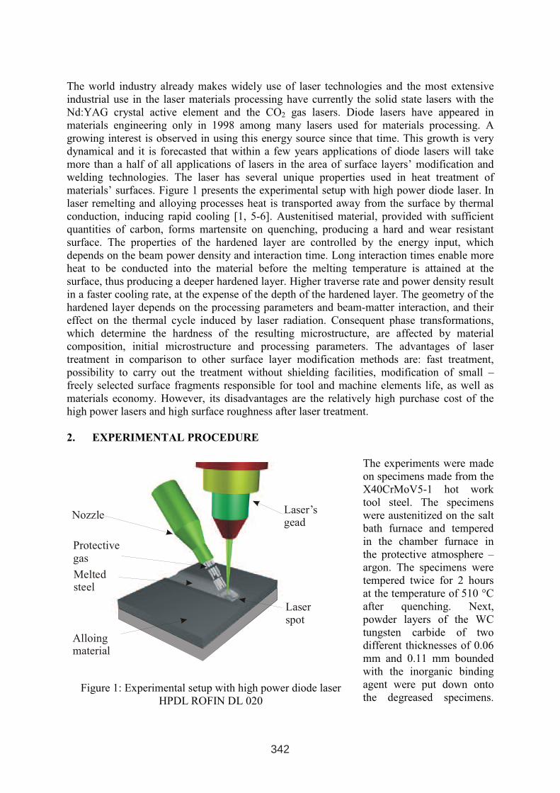
The world industry already makes widely use of laser technologies and the most extensive
industrial use in the laser materials processing have currently the solid state lasers with the
Nd:YAG crystal active element and the CO2 gas lasers. Diode lasers have appeared in
materials engineering only in 1998 among many lasers used for materials processing. A
growing interest is observed in using this energy source since that time. This growth is very
dynamical and it is forecasted that within a few years applications of diode lasers will take
more than a half of all applications of lasers in the area of surface layers’ modification and
welding technologies. The laser has several unique properties used in heat treatment of
materials’ surfaces. Figure 1 presents the experimental setup with high power diode laser. In
laser remelting and alloying processes heat is transported away from the surface by thermal
conduction, inducing rapid cooling [1, 5-6]. Austenitised material, provided with sufficient
quantities of carbon, forms martensite on quenching, producing a hard and wear resistant
surface. The properties of the hardened layer are controlled by the energy input, which
depends on the beam power density and interaction time. Long interaction times enable more
heat to be conducted into the material before the melting temperature is attained at the
surface, thus producing a deeper hardened layer. Higher traverse rate and power density result
in a faster cooling rate, at the expense of the depth of the hardened layer. The geometry of the
hardened layer depends on the processing parameters and beam-matter interaction, and their
effect on the thermal cycle induced by laser radiation. Consequent phase transformations,
which determine the hardness of the resulting microstructure, are affected by material
composition, initial microstructure and processing parameters. The advantages of laser
treatment in comparison to other surface layer modification methods are: fast treatment,
possibility to carry out the treatment without shielding facilities, modification of small –
freely selected surface fragments responsible for tool and machine elements life, as well as
materials economy. However, its disadvantages are the relatively high purchase cost of the
high power lasers and high surface roughness after laser treatment.
2. EXPERIMENTAL PROCEDURE
The experiments were made
on specimens made from the
X40CrMoV5-1 hot work
tool steel. The specimens
were austenitized on the salt
bath furnace and tempered
in the chamber furnace in
the protective atmosphere –
argon. The specimens were
tempered twice for 2 hours
at the temperature of 510 °C
after quenching. Next,
powder layers of the WC
tungsten carbide of two
different thicknesses of 0.06
mm and 0.11 mm bounded
with the inorganic binding
agent were put down onto
the degreased specimens.
Laser’sgead
Meltedsteel
Protectivegas
Nozzle
Laserspot
Alloing material
Figure 1: Experimental setup with high power diode laser
HPDL ROFIN DL 020
342
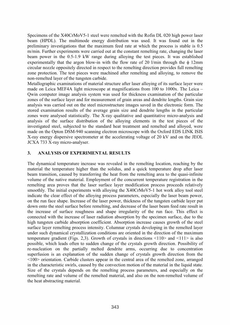
Specimens of the X40CrMoV5-1 steel were remelted with the Rofin DL 020 high power laser
beam (HPDL). The multimode energy distribution was used. It was found out in the
preliminary investigations that the maximum feed rate at which the process is stable is 0.5
m/min. Further experiments were carried out at the constant remelting rate, changing the laser
beam power in the 0.5-1.9 kW range during alloying the test pieces. It was established
experimentally that the argon blow-in with the flow rate of 20 l/min through the φ 12mm
circular nozzle oppositely directed in respect to the remelting direction provides full remelting
zone protection. The test pieces were machined after remelting and alloying, to remove the
non-remelted layer of the tungsten carbide.
Metallographic examinations of material structure after laser alloying of its surface layer were
made on Leica MEF4A light microscope at magnifications from 100 to 1000x. The Leica –
Qwin computer image analysis system was used for thickness examination of the particular
zones of the surface layer and for measurement of grain areas and dendrite lengths. Grain size
analysis was carried out on the steel microstructure images saved in the electronic form. The
stored examination results of the average grain size and dendrite lengths in the particular
zones were analysed statistically. The X-ray qualitative and quantitative micro-analysis and
analysis of the surface distribution of the alloying elements in the test pieces of the
investigated steel, subjected to the standard heat treatment and remelted and alloyed, were
made on the Opton DSM-940 scanning electron microscope with the Oxford EDS LINK ISIS
X-ray energy dispersive spectrometer at the accelerating voltage of 20 kV and on the JEOL
JCXA 733 X-ray micro-analyser.
3. ANALYSIS OF EXPERIMENTAL RESULTS
The dynamical temperature increase was revealed in the remelting location, reaching by the
material the temperature higher than the solidus, and a quick temperature drop after laser
beam transition, caused by transferring the heat from the remelting area to the quasi-infinite
volume of the native material. Employment of the concurrent temperature registration in the
remelting area proves that the laser surface layer modification process proceeds relatively
smoothly. The initial experiments with alloying the X40CrMoV5-1 hot work alloy tool steel
indicate the clear effect of the alloying process parameters, especially the laser beam power,
on the run face shape. Increase of the laser power, thickness of the tungsten carbide layer put
down onto the steel surface before remelting, and decrease of the laser beam feed rate result in
the increase of surface roughness and shape irregularity of the run face. This effect is
connected with the increase of laser radiation absorption by the specimen surface, due to the
high tungsten carbide absorption coefficient. Absorption increase causes growth of the steel
surface layer remelting process intensity. Columnar crystals developing in the remelted layer
under such dynamical crystallization conditions are oriented in the direction of the maximum
temperature gradient (Figs. 2,3). Growth of crystals in directions <110> and <111> is also
possible, which leads often to sudden change of the crystals growth direction. Possibility of
re-nucleation on the partially melted dendrite arms, occurring due to concentration
superfusion is an explanation of the sudden change of crystals growth direction from the
<100> orientation. Carbide clusters appear in the central area of the remelted zone, arranged
in the characteristic swirls, caused by the convection motion of the material in the liquid state.
Size of the crystals depends on the remelting process parameters, and especially on the
remelting rate and volume of the remelted material, and also on the non-remelted volume of
the heat abstracting material.
343
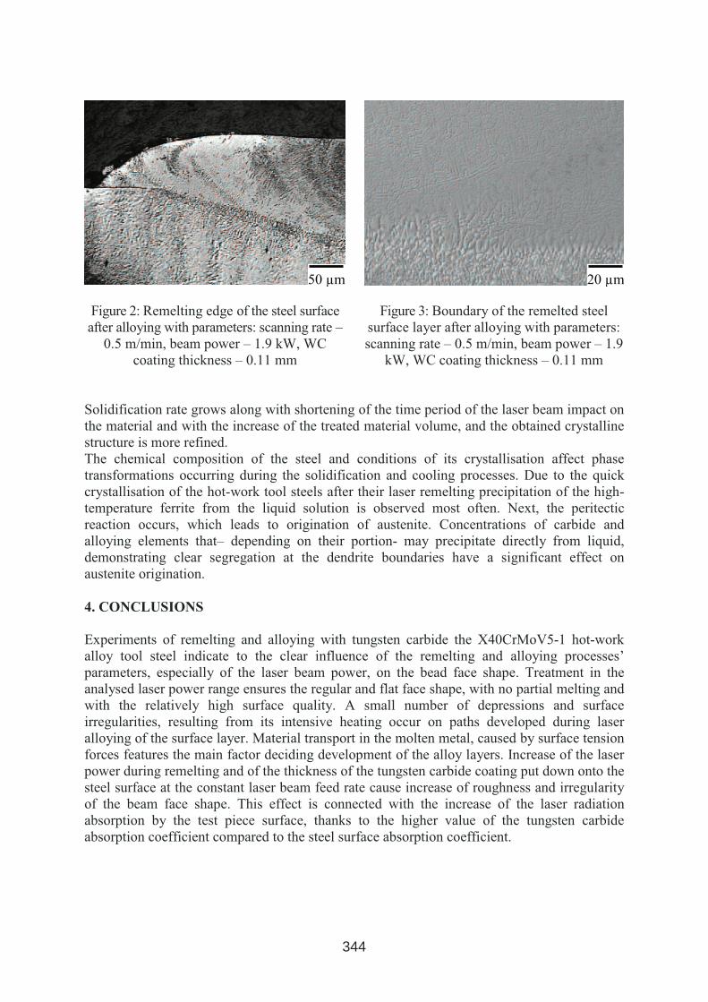
Figure 2: Remelting edge of the steel surface
after alloying with parameters: scanning rate –
0.5 m/min, beam power – 1.9 kW, WC
coating thickness – 0.11 mm
Figure 3: Boundary of the remelted steel
surface layer after alloying with parameters:
scanning rate – 0.5 m/min, beam power – 1.9
kW, WC coating thickness – 0.11 mm
Solidification rate grows along with shortening of the time period of the laser beam impact on
the material and with the increase of the treated material volume, and the obtained crystalline
structure is more refined.
The chemical composition of the steel and conditions of its crystallisation affect phase
transformations occurring during the solidification and cooling processes. Due to the quick
crystallisation of the hot-work tool steels after their laser remelting precipitation of the high-
temperature ferrite from the liquid solution is observed most often. Next, the peritectic
reaction occurs, which leads to origination of austenite. Concentrations of carbide and
alloying elements that– depending on their portion- may precipitate directly from liquid,
demonstrating clear segregation at the dendrite boundaries have a significant effect on
austenite origination.
4. CONCLUSIONS
Experiments of remelting and alloying with tungsten carbide the X40CrMoV5-1 hot-work
alloy tool steel indicate to the clear influence of the remelting and alloying processes’
parameters, especially of the laser beam power, on the bead face shape. Treatment in the
analysed laser power range ensures the regular and flat face shape, with no partial melting and
with the relatively high surface quality. A small number of depressions and surface
irregularities, resulting from its intensive heating occur on paths developed during laser
alloying of the surface layer. Material transport in the molten metal, caused by surface tension
forces features the main factor deciding development of the alloy layers. Increase of the laser
power during remelting and of the thickness of the tungsten carbide coating put down onto the
steel surface at the constant laser beam feed rate cause increase of roughness and irregularity
of the beam face shape. This effect is connected with the increase of the laser radiation
absorption by the test piece surface, thanks to the higher value of the tungsten carbide
absorption coefficient compared to the steel surface absorption coefficient.
50 µm 20 µm
344
ACKNOWLEDGMENTS
Investigations were partially financed within the frameworks of the Polish State Committee
for Scientific Research No 4 T08C 051 25 grant headed by Dr. E. Hajduczek and PBZ-
100/4/T08/2004 headed by Prof. L.A. Dobrzański. Authors participate in the CEEPUS
No PL-013/04-05 project headed by Prof. L.A. Dobrzański.
REFERENCES
1. W.M. Steen: Laser Materials Processing. Second Edition, Springer Verlag, 1998.
2. E.R. Fabian, P. Boross, B. Verö, P. Fülöp, Metallographic Aspects of Surface-Treated
steels by using Laser Technology, Mat. Sci. Forum, Vols. 414-415, 2003, p. 110-115.
3. L.A. Dobrzański, M. Bonek, E. Hajduczek, A. Klimpel, Application of high power diode
laser (HPDL) for alloying of X40CrMoV5-1 steel surface layer by tungsten carbides
Journal of Mat. Proc. Tech. 155-156, 2004, p. 1956-1963.
4. L.A. Dobrzański, M. Bonek, E. Hajduczek, A. Klimpel, Structure and properties of
surface layers obtained by laser treatment of the hot-work tool steel, Materials
Engineering, Vol. 3(140), 2004, pp. 564-567.
5. L.A. Dobrzański, M. Bonek, A. Klimpel, A. Lisiecki, Surface layer’s structure of
X40CrMoV5-1 steel remelted and/or WC alloyed with HPDL laser, Mat. Sci. Forum,
Vols. 437-438, 2003, p. 69-72.
6. L.A. Dobrzański, M. Bonek, E. Hajduczek, A. Klimpel, Development of surface layers
alloyed by HPDL laser on hot-work tool steel, 3rd International Conference on Advance
Materials Processing ICAMP-3, Melbourne, Australia, 2004, p. 184-189.
345