Embed Size (px)
Citation preview

MANUFACTURING
PROCESSES USED IN
MAKING AN ENGINE
-SIDDHARTH SHARMA(2012B1AB198H)
-MUKESH REDDY (2012B1AB746H)
-SANCHAY BAPAT(
-HEMANTH VARMA(
-MITHILESH MUNDHADA(

HOW TO MANUFACTURE AN
ENGINE??
Components covered in this presentation :
1. Engine Block
2. Pistons
3. Crank shafts
4. Gears
ENGINE BLOCK
•Main structure which gives space for cylinders
•traditionally used raw material is cast iron alloys
•presently aluminium alloys are used because of its
low weight
319 aluminium alloy contains
85.8 - 91.5 % of aluminium
5.5 - 6.5 % of silicon
3 - 4 % of copper
0.35% of nickel
0.25% of titanium
0.5% of manganese
1% of iron, 0.1% of magnesium, and 1% of zinc.

Process used: casting

CRANK SHAFTS
•converts the force created by the engine's pistons
moving up and down into a force that moves the
wheels in a circular motion so the car can go forward
•A pressure of 200 bar acting on a 4.00 inch diameter
piston produces a force of 36,442 pounds.
•steel alloys are the solution to the problem
Medium-carbon steel alloys, composed of
predominantly the element iron and contain a small
percentage of carbon.
•Main processes : casting , forging , turning, drilling

GEARS
•Used in transmitting power and motion
•High tensile strength to prevent failure
against static loads
•High endurance strength to withstand dynamic
loads
•Low coefficient of friction
•Good manufacturability
•Processes used - Gear forming , Form milling,
Broaching
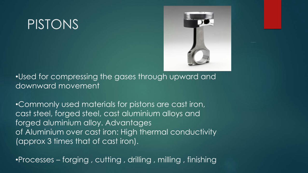
PISTONS
•Used for compressing the gases through upward and
downward movement
•Commonly used materials for pistons are cast iron,
cast steel, forged steel, cast aluminium alloys and
forged aluminium alloy. Advantages
of Aluminium over cast iron: High thermal conductivity
(approx 3 times that of cast iron).
•Processes – forging , cutting , drilling , milling , finishing

Engine Block Manufacturing

Properties
Strength
Modulus of Elasticity
Abrasion Resistance
Corrosion Resistance
Low Density
Thermal Expansion
Thermal Conductivity

Types of Materials
Gray Cast Iron Alloys
Compacted Graphite Cast Iron
Aluminum Alloy
Magnesium Alloy
Gray Cast
Iron Alloy
Compacted
Graphite cast
Al-Alloy
A356-T6
Mg-Alloy
AMC-SC1
Tensile Strength 160-320 MPa 300-600 MPa 215 MPa 117 MPa
Modulus of Elasticity 96-110 MPa 170-190 MPa 74.5 MPa

Casting1.Green Sand Molding
Zircon Sand(ZrSio4),Clay and Water
Molds made up of sections called CORES
Mold is compacted by squeezing and jolting
Also has 17 other cores
Molten Alloy is poured into it from bottom
Heat Treatment
Grinding

Quality Measures
Strength of Sand
Permeability in the size of grains
Thermal stability of Mold
Reusability
Cooling rate
GEAR MANUFACTURING
Gears are among the most important of all machine
elements because of their capability for transmitting
motion and power.
Two principal methods of gear manufacturing include Œ:
- gear forming and
- gear generation.

Gear forming :
The cutting edge of the
cutting tool has a shape identical with the
shape of the space between the gear teeth.
Two machining operations, milling and
broaching can be employed to form
cut gear teeth.
Form milling:
In form milling, the cutter called a
form cutter travels axially along
the length of the gear tooth
at the appropriate depth to produce
the gear tooth.
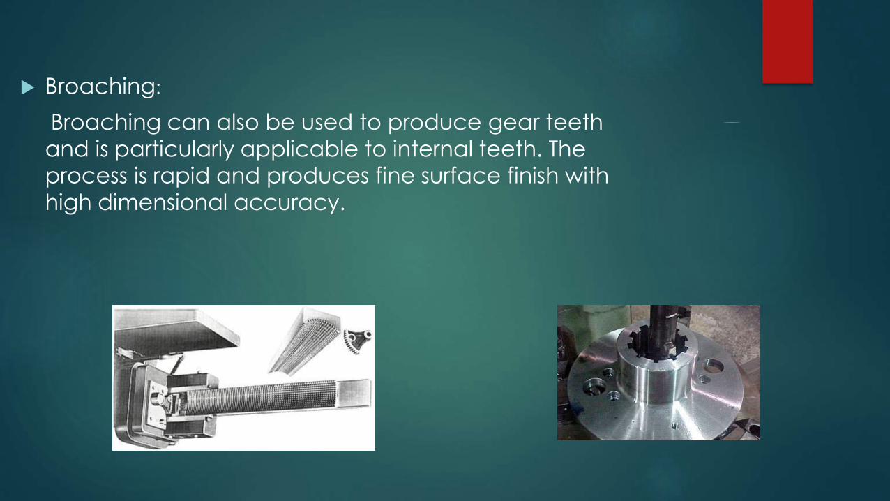
Broaching:
Broaching can also be used to produce gear teeth
and is particularly applicable to internal teeth. The
process is rapid and produces fine surface finish with
high dimensional accuracy.
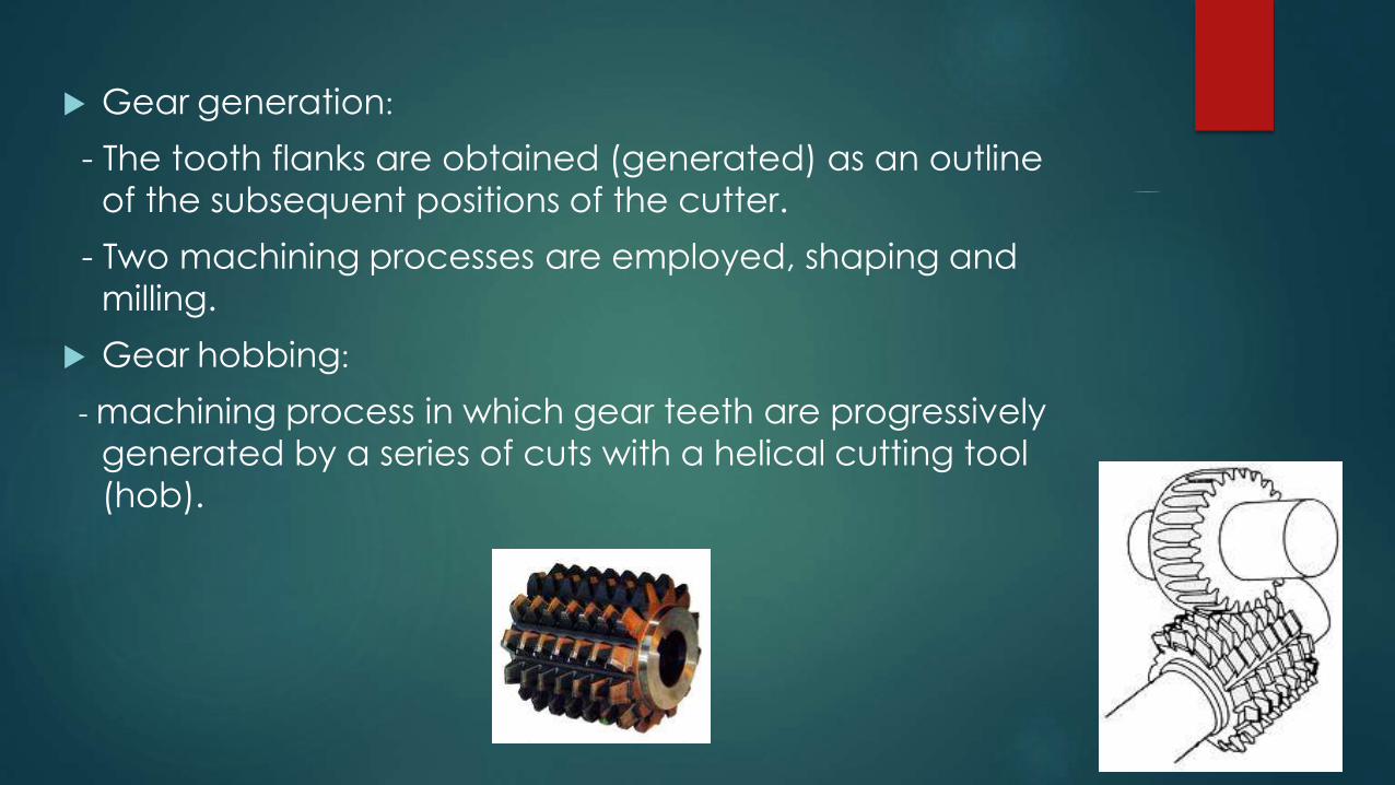
Gear generation:
- The tooth flanks are obtained (generated) as an outline
of the subsequent positions of the cutter.
- Two machining processes are employed, shaping and
milling.
Gear hobbing:
- machining process in which gear teeth are progressively
generated by a series of cuts with a helical cutting tool
(hob).

Shaping with a pinion-shaped cutter
- The cutter axis is parallel to the gear axis.
- The tool is called gear cutter and resembles in shape
the mating gear from the conjugate gear pair, the
other gear being the blank.
- High dimensional accuracy achieved and the not too
expensive tool.

Shaping with a rack-shaped cutter
- Gear teeth are generated by a cutting tool called a rack shaper.
- Rack shaper reciprocates parallel to the axis of the gear axis.
- Involve a very high dimensional accuracy and cheap cutting tool.
- Used for low-quantity as well as high-quantity production of spur and helix external
gears.
Finishing operations:
Several finishing operations are available, including the conventional process of shaving, and a number of abrasive operations, including grinding, honing, and
lapping.

Manufacturing of Piston

Manufacturing of Piston –
THE ROD
• An Aluminium rod is cut into smaller
pieces called slugs by a Rotary saw
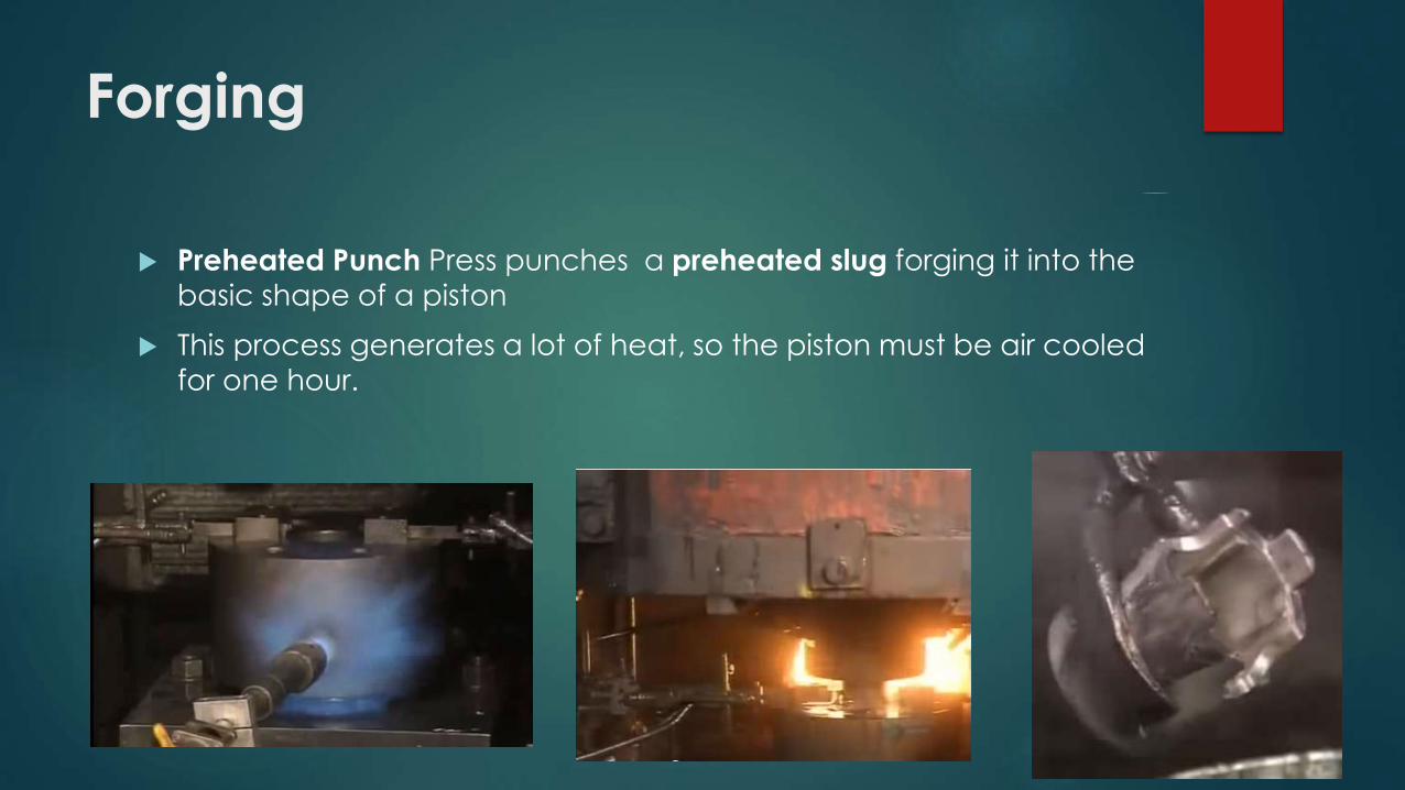
Forging
Preheated Punch Press punches a preheated slug forging it into the
basic shape of a piston
This process generates a lot of heat, so the piston must be air cooled for one hour.

Cutting/Drilling
A lathe is then used to cut excess metal from the basic form ,
impresses three rings ,taking it closer to its finished shape.
Tiny holes are then drilled into the sides, to create the oil passages for the piston.

Drilling- Wrist pin holes
A large hole is then drilled through both sides of the piston. This is
where the wrist pin will go, which is used to attach the piston to the
connecting rod during engine assembly.

Milling
A milling machine then shaves up to a couple of centimeters off of
each side of the piston where the large holes were drilled for the
wrist pin insertion and also near the rings.

Finishing
Lathe shaves a few more milli meters off of the top, allowing the
piston to expand when heat builds up inside of it.
A human worker then smooths out the sharp edges of the piston created during production.
Finally, the pistons sprayed by hot, deionized water, removing any
lubricant or oil gathered through the manufacturing process. After
they're dry, they're ready for use.

Finishing

Manufacturing of Cam -Shafts
Manufacturing Process Explained Graphically
1) Shaping on the lathe :
2) Process to mill the pin :
1) The process to mill the weight :

4) Conditioning quality and shot peening :
5) Shaping on the lathe for the 2nd time :
6) Process to mill the pin :
7) The oil hole, the key slot, and the bolt hole processing :

8) The pin and the journal polishing process :
9) The dynamic balance adjustment process.
10) The pin and the journal wrapping process.
11) The surface treatment process.
12) The final wrapping, bend correction, and inspection process.
Tooling Required
To produce a crankshaft there are few main tools required:
1) Lathe machine.
2) Shaper.
3) Precision Drills.
4) Milling machine.

Manufacturing of Camshaft
METHODS OF MANUFACTURING:
1. CASTING: More chances of casting defects such as shrinkage defect, porosity, crack, insufficient
pouring.
2. FORGING:
• used for certain high loaded diesel engines.
• produced on computer-controlled forging systems with integrated heat treatment or machined
from steel bar.
3. MACHINING:
A detailed description of the processes for mass manufacturing is as follows:
1.TURNING & DRILLING: The raw forging is put in this machine
and center drilling and turning on one side
is done here.

2. TURNING: Here the turning of the journals takes place. Also,
Grooving and Parting operation is performed on the left side of
the shaft.
3. DRILLING: This machine drills the hole which is used as reference for
further operations.
4. GRINDING JOURNALS: Here grinding and finish
grinding of the journals takes place.
Carborundum wheels are used for grinding
5. GRINDING ON FACE: An angular grinding wheel is used for the face
grinding operation. At this stage, inspection is done after every 10
components using gauges

6. LAPPING: To give superfinish in microns, lapping is done using lapping
paper on the Cams and the Oil seal area.
7. SLITTING: This machine makes a slit in the right side of the shaft to fit in
the engine. The cutter used is a Saw cutter and pneumatic deburring is
done here.
8. AIR & WATER CLEANING: This is the Washing Machine where water and
air jets are used to clean the component of dust, oil, chips etc.
9. INSPECTION: This is a Measuring Machine used to check for
tolerances - Runouts and Diameters of journals. The machine then declares the
component as OK, NG, or BAD.


![Installation of Gas Engine Cogeneration System to …gec.jp/jcm/seminar/2019indonesia/4-3_TMMIN.pdfPT. Toyota Motor Manufacturing Indonesia [TMMIN] Installation of Gas Engine Cogeneration](https://img.pdfslide.us/doc/110x75/5f7bc5274de67451ae73a8a2/installation-of-gas-engine-cogeneration-system-to-gecjpjcmseminar2019indonesia4-3tmminpdf.jpg)