Embed Size (px)
Citation preview
HEAT TREATMENT
PROVEN TECHNOLOGIES AND INDUSTRIAL DEVELOPMENTS IN HEAT TREATMENTAND SURFACE ENGINEERING OF TOOLS AND DIESJ. Bach, F. Dambacher . . . . . . . . . . . . . . . . . . . . . . . . . . . . . . . . . . . . . . . . . . . . . . . . . . . . . . . . . . . . . . . . . . . . . . . . . . . . . . . . .1
PROCESS OPTIMISATION FOR DEEP COLD TREATMENT OF TOOL STEELSP. F. Stratton . . . . . . . . . . . . . . . . . . . . . . . . . . . . . . . . . . . . . . . . . . . . . . . . . . . . . . . . . . . . . . . . . . . . . . . . . . . . . . . . . . . . . . . .11
WEAR BEHAVIOUR OF DEEP CRYOGENIC TREATED HIGH SPEED STEELSM. Kalin, V. Leskovšek, J. Vižintin . . . . . . . . . . . . . . . . . . . . . . . . . . . . . . . . . . . . . . . . . . . . . . . . . . . . . . . . . . . . . . . . . . . . . . .21
IMPROVING TOOL PRODUCT PERFORMANCE THOUGH THE USEOF INTENSIVE QUENCHING PROCESSESM.A. Aronov, J.A. Powell, N.I. Kobasko . . . . . . . . . . . . . . . . . . . . . . . . . . . . . . . . . . . . . . . . . . . . . . . . . . . . . . . . . . . . . . . . . . .27
VACUUM FURNACE - INTEGRATED "SUB-ZERO" TREATMENTB. Zieger, R. Stein . . . . . . . . . . . . . . . . . . . . . . . . . . . . . . . . . . . . . . . . . . . . . . . . . . . . . . . . . . . . . . . . . . . . . . . . . . . . . . . . . . .33
THE MAIN PRINCIPLES OF INTENSIVE QUENCHING OF TOOLS AND DIESN.I. Kobasko . . . . . . . . . . . . . . . . . . . . . . . . . . . . . . . . . . . . . . . . . . . . . . . . . . . . . . . . . . . . . . . . . . . . . . . . . . . . . . . . . . . . . . . .39
OPTIMIZING THE VACUUM-HEAT-TREATMENT OF HOT-WORK TOOL STEELS BYLINEAR ELASTIC FRACTURE MECHANICSV. Leskovšek, B. Šuštaršiè, G. Jutriša, D. Baksa, J. Kopaè . . . . . . . . . . . . . . . . . . . . . . . . . . . . . . . . . . . . . . . . . . . . . . . . . . . .45
MICROSTRUCTURAL EVOLUTION OF A RAPIDLY SOLIDIFIED HIGH-SPEEDSTEEL DURING HIGH TEMPERATURE ANNEALINGC. Stotter, H. Leitner, R. Ebner, P. Ramminger, E. Brandstätter . . . . . . . . . . . . . . . . . . . . . . . . . . . . . . . . . . . . . . . . . . . . . . . .53
HIGH TEMPERATURE BRAZING OF HIGH TEC COMPONENTS - A THERMALPROCESSING WITH SPECIFIC REQUIREMENTSI. Reinkensmeier, H. Buursen . . . . . . . . . . . . . . . . . . . . . . . . . . . . . . . . . . . . . . . . . . . . . . . . . . . . . . . . . . . . . . . . . . . . . . . . . . .63
IMPROVED PRODUCTION OF STEEL PARTS BY INTENSIVE QUENCHINGN.I. Kobasko, L.C.F. Canale, G.E. Totten . . . . . . . . . . . . . . . . . . . . . . . . . . . . . . . . . . . . . . . . . . . . . . . . . . . . . . . . . . . . . . . . . .69
THE USE OF A NEW TYPE OF LARGE VACUUM BATCH FURNACE FOR THEHEAT TREATMENT OF MOULDS AND DIESTh. Wingens, B. Edenhofer, O. Irretier . . . . . . . . . . . . . . . . . . . . . . . . . . . . . . . . . . . . . . . . . . . . . . . . . . . . . . . . . . . . . . . . . . . .77
SINGLE AND MULTI-CHAMBER VACUUM FURNACES FOR TOOLS AND DIES HEAT TREATMENTD. Siniarski, M. Korecki . . . . . . . . . . . . . . . . . . . . . . . . . . . . . . . . . . . . . . . . . . . . . . . . . . . . . . . . . . . . . . . . . . . . . . . . . . . . . . .83
INFLUENCE OF THE PRETREATMENT THERMAL TREATMENT ON THE MICROSTRUCTUREAND PROPERTIES OF X37CRMOV5-1 STEELJ. Jasiñski, R. Torbus, E. Kasprzycka, B. Bogdañski . . . . . . . . . . . . . . . . . . . . . . . . . . . . . . . . . . . . . . . . . . . . . . . . . . . . . . . . .91
INFLUENCE OF QUENCHING OILS COMPOSITION ON THE COOLING RATEL. Pedišiæ, B. Matijeviæ, B. Periæ . . . . . . . . . . . . . . . . . . . . . . . . . . . . . . . . . . . . . . . . . . . . . . . . . . . . . . . . . . . . . . . . . . . . . . . . .97
THE INFLUENCE OF MULTIPLE SOLUTION ANNEALING ON KINETICSOF STRUCTURAL TRANSFORMATION OF MARAGING STEELS I. Kladariæ, D. Krumes, R. Markoviæ . . . . . . . . . . . . . . . . . . . . . . . . . . . . . . . . . . . . . . . . . . . . . . . . . . . . . . . . . . . . . . . . . . . . .107
CONTAINS
PROVEN TECHNOLOGIES AND INDUSTRIAL DEVELOPMENTSIN HEAT TREATMENT AND SURFACE ENGINEERING
OF TOOLS AND DIES
J. Bach, F. Dambacher
1. INTRODUCTION
Increasing requirements in terms of the quality of the products as well as the processing of new materials require even more extreme processing conditions. Tools and materials often do not any longer fulfil the rising requirements satisfactorily. The consequence is in particular the increase of wear of the tool surfaces. Beside the optimal selection of the materials as well as their heat treatment technologies of the surface treatment gain strongly significance. The presented contribution concerns itself with the demand-fair heat treatment of selected steels, the barrier layer treatment by plasma nitriding, as well as a special surface treatment, the PVD-coating.
2. BASICS
2.1 Heat treatment technology
An iron carbon alloy with a carbon content < 2.06 % is called steel. Beside the main alloying element carbon the characteristics of the steel can be affected by different alloying elements considerably. Heat treatment of steels is based on a lattice transformation at a temperature of 911°C (for pure iron). At this temperature the
cubically body-centered α-iron (ferrite) converts into the cubically face-centered γ-iron (austenite). Apart from the different type of lattice these two types differ in their carbon solubility. In the ferrite the solubility limit is about 0.02 weight- %, higher contents lead to the formation of cementite (iron carbide Fe3C).
H-O-T Härte- und Oberflächentechnik GmbH & Co. KG Kleinreuther Weg 118 90425 Nürnberg
ÄRTE- UND BERFLÄCHEN ECHNIKH O T
1
1 INTERNATIONAL CONFERENCE ON HEAT TREATMENT
AND SURFACE ENGINEERING OF TOOLS AND DIES
st
Pula, Croatia 08 - 11 June, 2005,
IFHTSE 2005
In the austenite lattice however up to 2 weight-% C can be solved. With the exceeding of the transformation temperature the cementite dissolves and carbon isdistributed evenly in the austenite. During rapid cooling solved carbon can’t seperate itself as iron carbide, but remains in a not stable obligation solution. With falling below an intended temperature martensite formation begins with turning the austenite lattice into a tetragonally distorted lattice, in which obligation-solved carbon leads to high spanning and thus high hardness. For reaching the martensite transformation the following points must be fulfilled:
warming up the steel to temperatures higher than transformation temperature
cooling velocity higher than critical cooling velocity falling below a critical temperature (martensite starting-temperature)
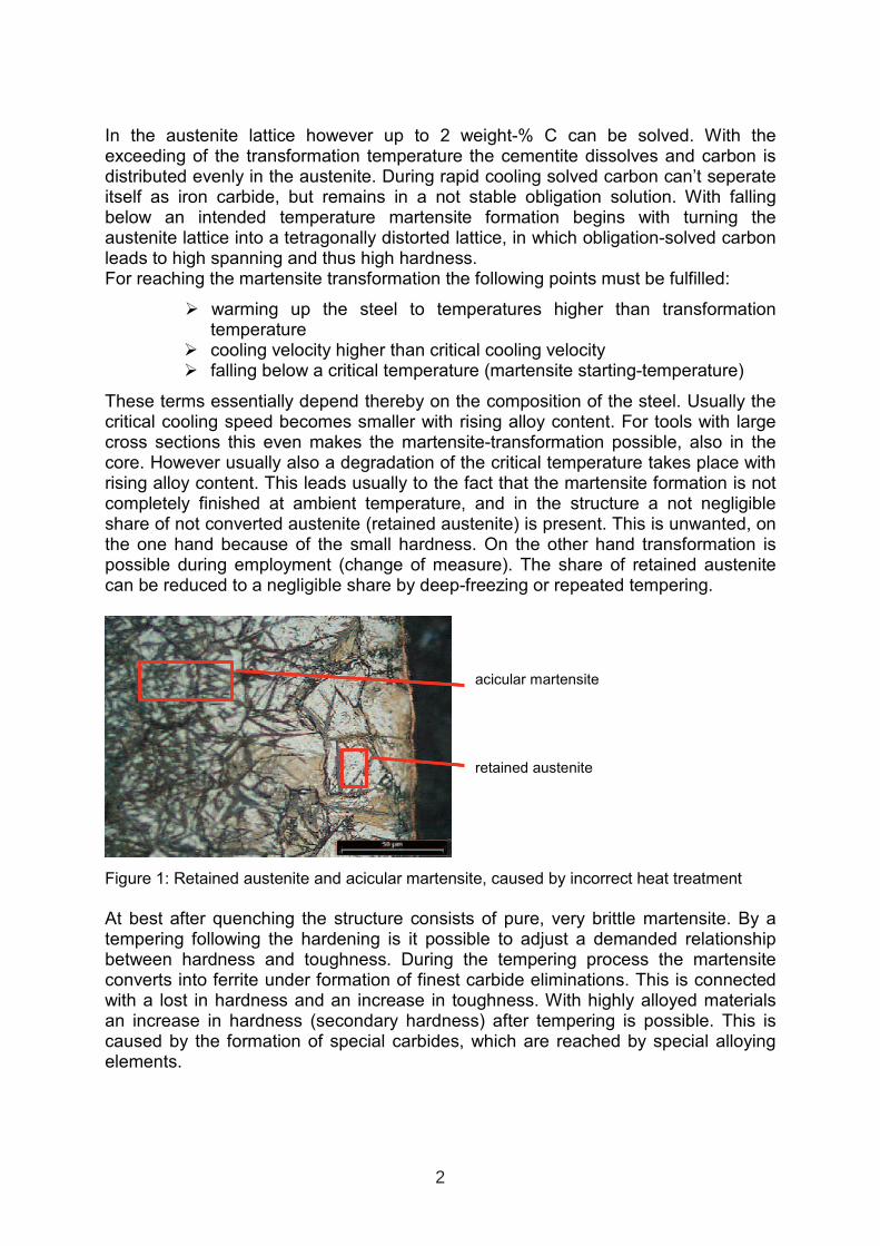
These terms essentially depend thereby on the composition of the steel. Usually the critical cooling speed becomes smaller with rising alloy content. For tools with large cross sections this even makes the martensite-transformation possible, also in the core. However usually also a degradation of the critical temperature takes place with rising alloy content. This leads usually to the fact that the martensite formation is not completely finished at ambient temperature, and in the structure a not negligible share of not converted austenite (retained austenite) is present. This is unwanted, on the one hand because of the small hardness. On the other hand transformation is possible during employment (change of measure). The share of retained austenite can be reduced to a negligible share by deep-freezing or repeated tempering.
nadeliger Martensit
Restaustenit
nadeliger Martensit
Restaustenit
nadeliger Martensit
Restaustenit
Figure 1: Retained austenite and acicular martensite, caused by incorrect heat treatment
At best after quenching the structure consists of pure, very brittle martensite. By a tempering following the hardening is it possible to adjust a demanded relationship between hardness and toughness. During the tempering process the martensite converts into ferrite under formation of finest carbide eliminations. This is connected with a lost in hardness and an increase in toughness. With highly alloyed materials an increase in hardness (secondary hardness) after tempering is possible. This is caused by the formation of special carbides, which are reached by special alloying elements.
acicular martensite
retained austenite
2
The most modern heat treatment process is the vacuum process, which isaccomplished in special vacuum furnaces with pressures of ~0,1mbar. As quenching media inert gas (e.g. N2, He) is used, flowing with overpressure into the vacuum chamber. The large advantage of the vacuum heat treatment is an oxidation-free surface after the treatment. Due to the small quenching effect this procedure is suitable only for high-alloyed steel.
Hard
ness
[HV
30
]
Tempering temperature [°C]
Hard
ness
[HV
30
]
Tempering temperature [°C]
Figure 2: Temper curves of unalloyed and alloyed steels. With highly alloyed materials an increase in hardness is possible.
2.2 Plasma nitriding technology
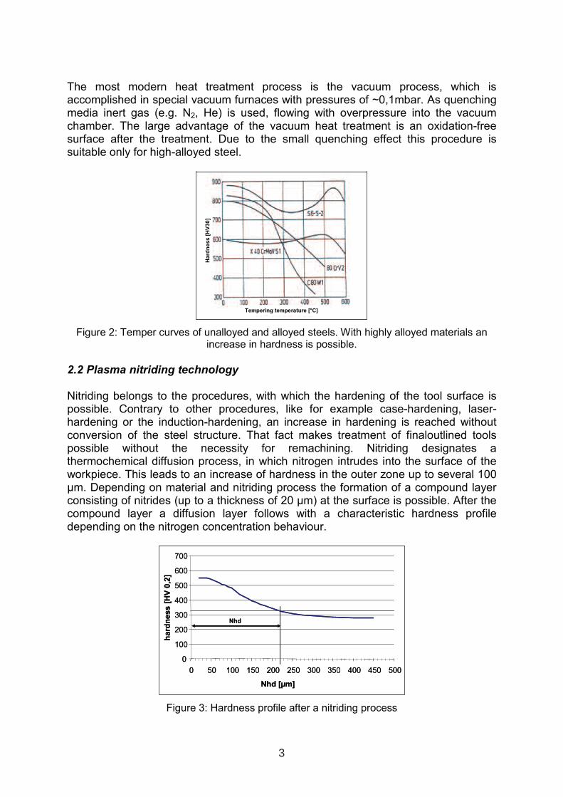
Nitriding belongs to the procedures, with which the hardening of the tool surface is possible. Contrary to other procedures, like for example case-hardening, laser-hardening or the induction-hardening, an increase in hardening is reached without conversion of the steel structure. That fact makes treatment of finaloutlined tools possible without the necessity for remachining. Nitriding designates a thermochemical diffusion process, in which nitrogen intrudes into the surface of the workpiece. This leads to an increase of hardness in the outer zone up to several 100 µm. Depending on material and nitriding process the formation of a compound layer consisting of nitrides (up to a thickness of 20 µm) at the surface is possible. After the compound layer a diffusion layer follows with a characteristic hardness profile depending on the nitrogen concentration behaviour.
0
100
200
300
400
500
600
700
0 50 100 150 200 250 300 350 400 450 500
Nhd [µm]
hard
ness
[HV
0,2
]
Nhd
0
100
200
300
400
500
600
700
0 50 100 150 200 250 300 350 400 450 500
Nhd [µm]
hard
ness
[HV
0,2
]
Nhd
Figure 3: Hardness profile after a nitriding process
3
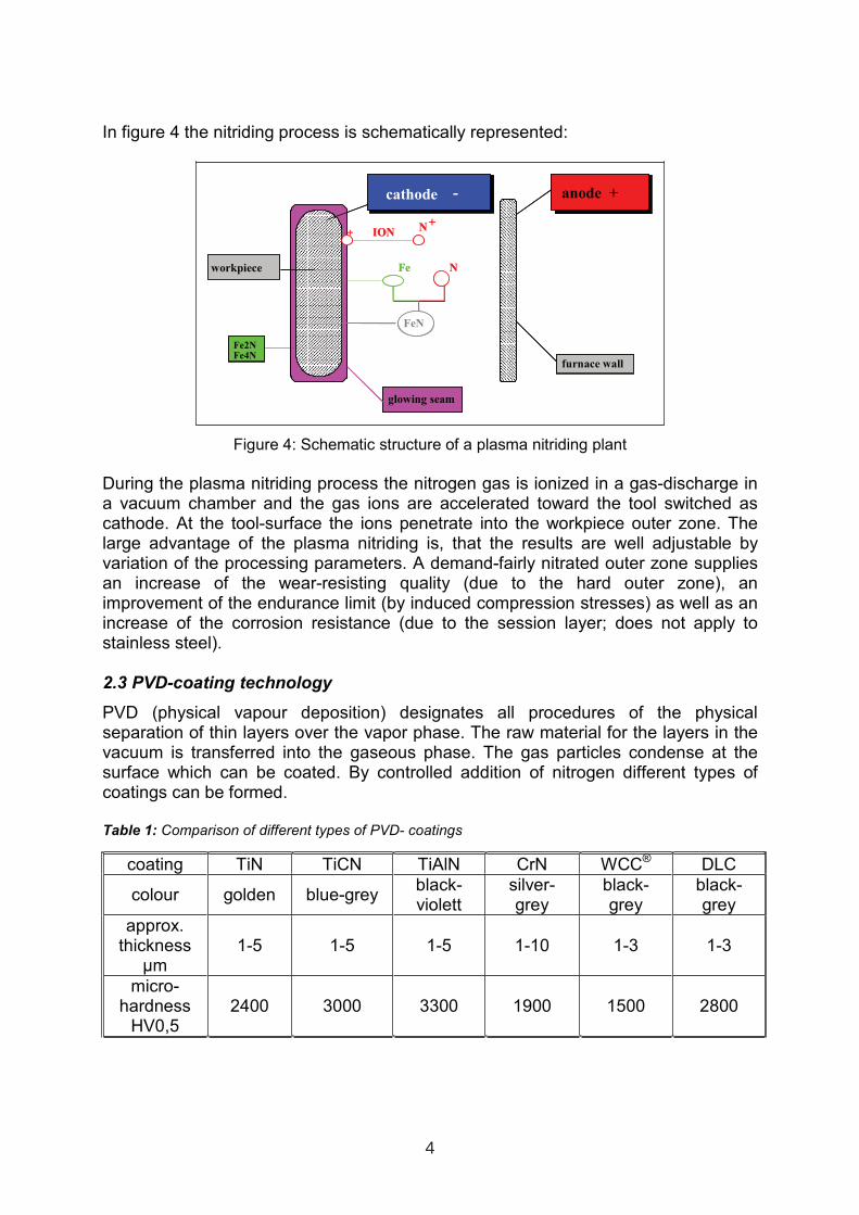
In figure 4 the nitriding process is schematically represented:
cathode -
++ ION
Fe N
Fe2NFe4N
glowing seam
workpiece
furnace wall
FeN
anode +
N
cathode -
++ ION
Fe N
Fe2NFe4N
glowing seam
workpiece
furnace wall
FeN
anode +
N
Figure 4: Schematic structure of a plasma nitriding plant
During the plasma nitriding process the nitrogen gas is ionized in a gas-discharge in a vacuum chamber and the gas ions are accelerated toward the tool switched ascathode. At the tool-surface the ions penetrate into the workpiece outer zone. The large advantage of the plasma nitriding is, that the results are well adjustable by variation of the processing parameters. A demand-fairly nitrated outer zone supplies an increase of the wear-resisting quality (due to the hard outer zone), an improvement of the endurance limit (by induced compression stresses) as well as an increase of the corrosion resistance (due to the session layer; does not apply to stainless steel).
2.3 PVD-coating technology
PVD (physical vapour deposition) designates all procedures of the physical separation of thin layers over the vapor phase. The raw material for the layers in the vacuum is transferred into the gaseous phase. The gas particles condense at the surface which can be coated. By controlled addition of nitrogen different types of coatings can be formed.
Table 1: Comparison of different types of PVD- coatings
coating TiN TiCN TiAlN CrN WCC® DLC
colour golden blue-grey black-violett
silver-grey
black-grey
black-grey
approx. thickness µm
1-5 1-5 1-5 1-10 1-3 1-3
micro-hardness
HV0,5 2400 3000 3300 1900 1500 2800
4
The advantages of PVD coatings are in detail:
very high surface hardness, with receipt of the toughness of the base material
small friction losses and good sliding qualities small layer thicknesses→ Accuracy to size remains
A common process is the so-called ARC- process. In a high-vacuum-chamber an arc between evaporator (cathode) and the surrounding chamber wall (anode) is ignited. Due to the high current density in the toe of the arc it comes to an emission like an explosion of atoms, ions and clusters from the evaporation material (e.g. Ti). Up to 90% of the emitted particles thereby are ionized. The tool which will be coated is put during the coating on negative potential. Due to ion bombardment it comes to a compression of the surface and to an improvement of the layer adhesion. The production of layers with good layer adhesion requires process temperatures of ~ 450 °C. This presupposes good tempering properties of for instance 500°C, in order to avoid inadvertent material transformations.
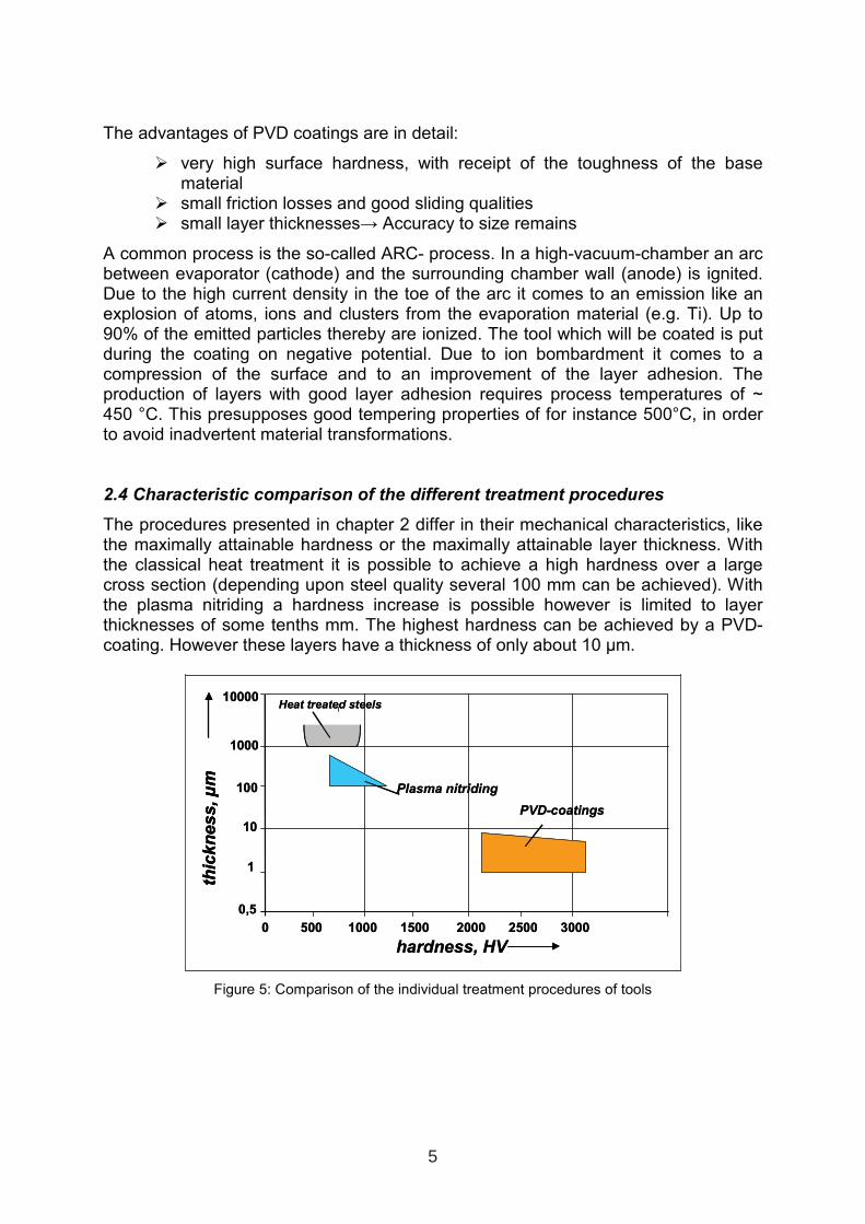
2.4 Characteristic comparison of the different treatment procedures
The procedures presented in chapter 2 differ in their mechanical characteristics, like the maximally attainable hardness or the maximally attainable layer thickness. With the classical heat treatment it is possible to achieve a high hardness over a large cross section (depending upon steel quality several 100 mm can be achieved). With the plasma nitriding a hardness increase is possible however is limited to layer thicknesses of some tenths mm. The highest hardness can be achieved by a PVD-coating. However these layers have a thickness of only about 10 µm.
hardness, HV
thic
kn
es
s,µ
m
0 500 1000 1500 2000 2500 3000
10000
1000
100
10
1
0,5
PVD-coatings
Plasma nitriding
Heat treated steels
hardness, HV
thic
kn
es
s,µ
mth
ick
nes
s,µ
m
0 500 1000 1500 2000 2500 3000
10000
1000
100
10
1
0,5
PVD-coatings
Plasma nitriding
Heat treated steels
Figure 5: Comparison of the individual treatment procedures of tools
5
3. Technology of heat and surface treatment
3.1 From the semi-finished material to the tool
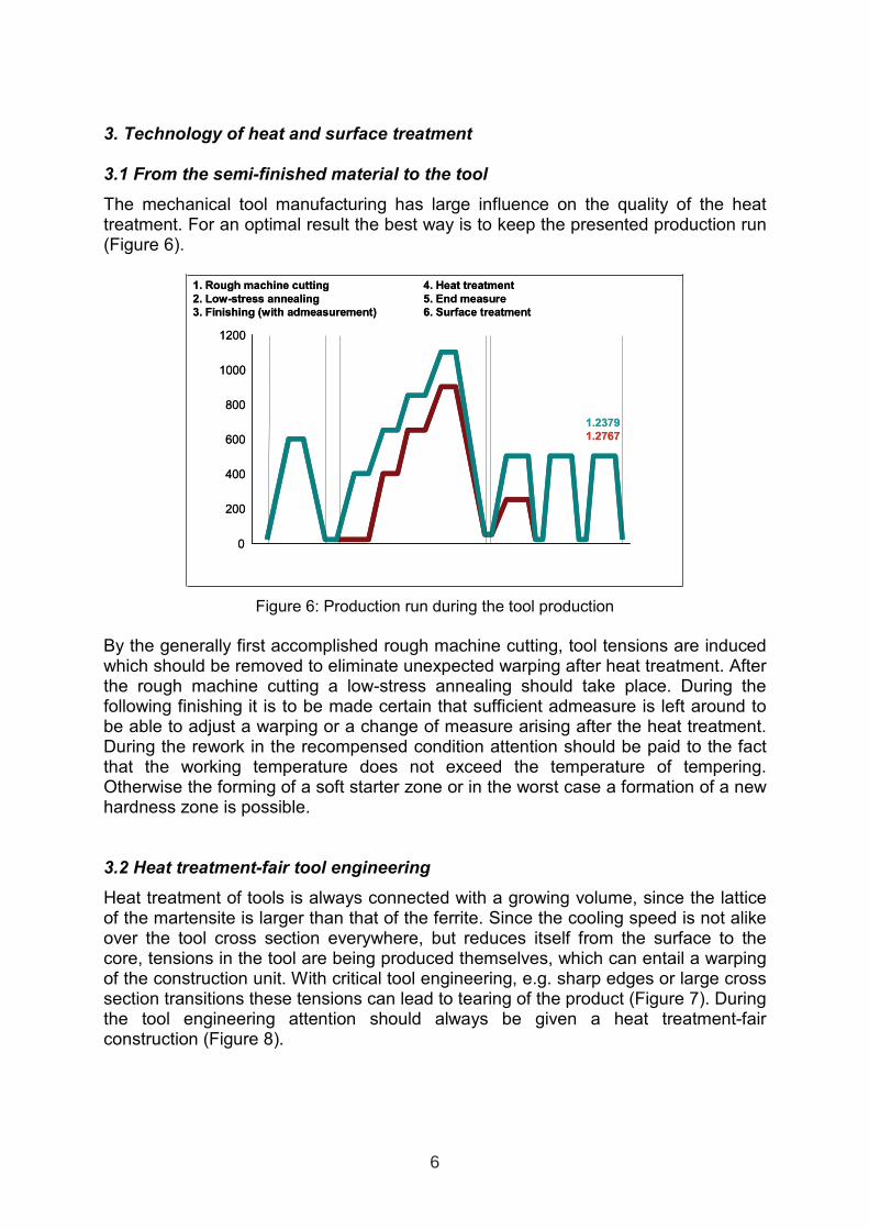
The mechanical tool manufacturing has large influence on the quality of the heat treatment. For an optimal result the best way is to keep the presented production run (Figure 6).
0
200
400
600
800
1000
1200
z.B. 1.2379
z.B 1.2767
1. Rough machine cutting 4. Heat treatment
2. Low-stress annealing 5. End measure
3. Finishing (with admeasurement) 6. Surface treatment
0
200
400
600
800
1000
1200
z.B. 1.2379
z.B 1.2767
1. Rough machine cutting 4. Heat treatment
2. Low-stress annealing 5. End measure
3. Finishing (with admeasurement) 6. Surface treatment
Figure 6: Production run during the tool production
By the generally first accomplished rough machine cutting, tool tensions are induced which should be removed to eliminate unexpected warping after heat treatment. After the rough machine cutting a low-stress annealing should take place. During the following finishing it is to be made certain that sufficient admeasure is left around to be able to adjust a warping or a change of measure arising after the heat treatment. During the rework in the recompensed condition attention should be paid to the fact that the working temperature does not exceed the temperature of tempering. Otherwise the forming of a soft starter zone or in the worst case a formation of a new hardness zone is possible.
3.2 Heat treatment-fair tool engineering
Heat treatment of tools is always connected with a growing volume, since the lattice of the martensite is larger than that of the ferrite. Since the cooling speed is not alike over the tool cross section everywhere, but reduces itself from the surface to the core, tensions in the tool are being produced themselves, which can entail a warping of the construction unit. With critical tool engineering, e.g. sharp edges or large cross section transitions these tensions can lead to tearing of the product (Figure 7). During the tool engineering attention should always be given a heat treatment-fair construction (Figure 8).
6
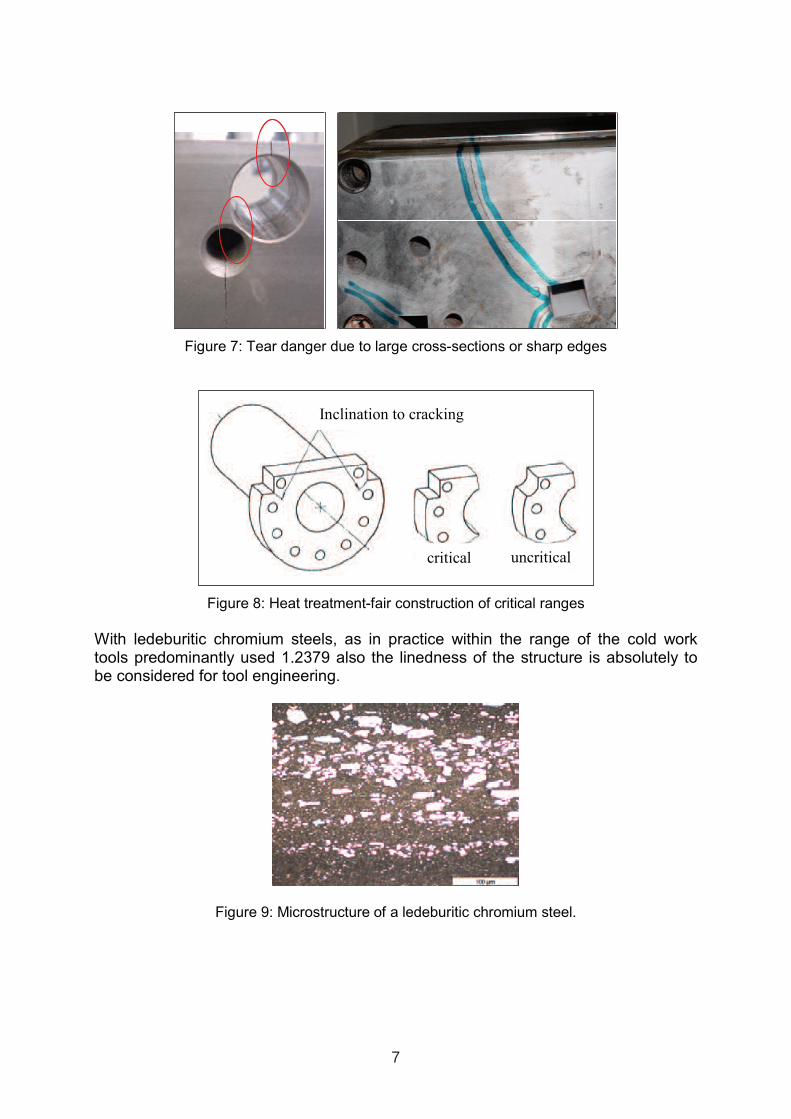
Figure 7: Tear danger due to large cross-sections or sharp edges
Figure 8: Heat treatment-fair construction of critical ranges
With ledeburitic chromium steels, as in practice within the range of the cold worktools predominantly used 1.2379 also the linedness of the structure is absolutely to be considered for tool engineering.
Figure 9: Microstructure of a ledeburitic chromium steel.
Inclination to cracking
critical uncritical
7
During the heat treatment and the associated changes of measure, tensions in the workpiece are called, which are in equilibrium. During the following rework it can occur now that a carbide line becomes split. Thus the tension household of the workpiece is changed, the consequence is warping. In practice it satisfactorily works to make discharge cuts into the semi-finished material, before the heat treatment. Thus the arising hardness tensions can be reduced, and so the danger of warping during the rework is smaller.
3.3 Heat and surface treatment of die casting and plastic moulds
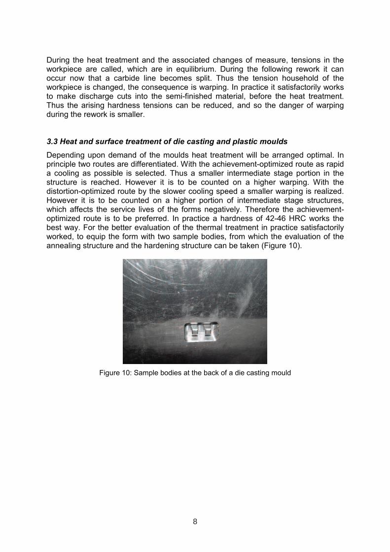
Depending upon demand of the moulds heat treatment will be arranged optimal. In principle two routes are differentiated. With the achievement-optimized route as rapid a cooling as possible is selected. Thus a smaller intermediate stage portion in the structure is reached. However it is to be counted on a higher warping. With the distortion-optimized route by the slower cooling speed a smaller warping is realized. However it is to be counted on a higher portion of intermediate stage structures, which affects the service lives of the forms negatively. Therefore the achievement-optimized route is to be preferred. In practice a hardness of 42-46 HRC works the best way. For the better evaluation of the thermal treatment in practice satisfactorily worked, to equip the form with two sample bodies, from which the evaluation of the annealing structure and the hardening structure can be taken (Figure 10).
Figure 10: Sample bodies at the back of a die casting mould
8
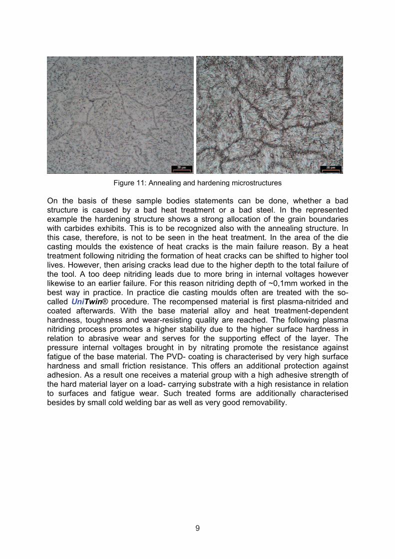
Figure 11: Annealing and hardening microstructures
On the basis of these sample bodies statements can be done, whether a bad structure is caused by a bad heat treatment or a bad steel. In the represented example the hardening structure shows a strong allocation of the grain boundaries with carbides exhibits. This is to be recognized also with the annealing structure. In this case, therefore, is not to be seen in the heat treatment. In the area of the die casting moulds the existence of heat cracks is the main failure reason. By a heat treatment following nitriding the formation of heat cracks can be shifted to higher tool lives. However, then arising cracks lead due to the higher depth to the total failure of the tool. A too deep nitriding leads due to more bring in internal voltages however likewise to an earlier failure. For this reason nitriding depth of ~0,1mm worked in the best way in practice. In practice die casting moulds often are treated with the so-called UniTwin® procedure. The recompensed material is first plasma-nitrided and coated afterwards. With the base material alloy and heat treatment-dependent hardness, toughness and wear-resisting quality are reached. The following plasma nitriding process promotes a higher stability due to the higher surface hardness in relation to abrasive wear and serves for the supporting effect of the layer. The pressure internal voltages brought in by nitrating promote the resistance against fatigue of the base material. The PVD- coating is characterised by very high surface hardness and small friction resistance. This offers an additional protection against adhesion. As a result one receives a material group with a high adhesive strength of the hard material layer on a load- carrying substrate with a high resistance in relation to surfaces and fatigue wear. Such treated forms are additionally characterised besides by small cold welding bar as well as very good removability.
9
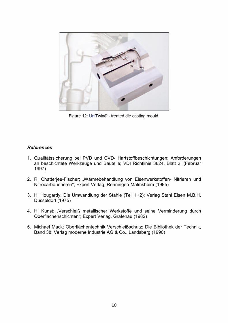
Figure 12: UniTwin® - treated die casting mould.
References
1. Qualitätssicherung bei PVD und CVD- Hartstoffbeschichtungen: Anforderungen an beschichtete Werkzeuge und Bauteile; VDI Richtlinie 3824, Blatt 2: (Februar 1997)
2. R. Chatterjee-Fischer; „Wärmebehandlung von Eisenwerkstoffen- Nitrieren und Nitrocarbouerieren“; Expert Verlag, Renningen-Malmsheim (1995)
3. H. Hougardy: Die Umwandlung der Stähle (Teil 1+2); Verlag Stahl Eisen M.B.H. Düsseldorf (1975)
4. H. Kunst: „Verschleiß metallischer Werkstoffe und seine Verminderung durch Oberflächenschichten“; Expert Verlag, Grafenau (1982)
5. Michael Mack; Oberflächentechnik Verschleißschutz; Die Bibliothek der Technik, Band 38; Verlag moderne Industrie AG & Co., Landsberg (1990)
10
PROCESS OPTIMISATION FOR DEEP COLD TREATMENT
OF TOOL STEELS
P F Stratton BOC, c/o 42 Park Lea, Bradley, UK
ABSTRACT
Deep cold treatment has been applied to many materials, but is best understood in the treatment of tools to improve their wear resistance. Even here, inconsistencies in processing techniques have led to different conclusions as to the exact mechanisms involved. This paper reviews current thinking and attempts to explain these differences in terms of the processing parameters and to elucidate the implications for the practical application of the technique for optimum properties. An optimised processing route is recommended and a possible further improvement in the process is suggested. Keyword: deep cold treatment, tool steels
1. INTRODUCTION
Despite much research over many years, deep cold treatment remains something of a mystery. It has been reported to improve the properties of everything from tool steels to golf balls and from nuns’ habits to copper spot welding electrodes. The greatest improvement reported is in wear properties. However, many of these miraculous transformations can be ascribed to the phenomenon of structure stabilisation. It has been suggested that the deep cold orders the structure, eliminating voids and dislocations so that slip is less likely [1, 2]. This is the reason for deep cold treating precision engineering parts that are exposed to rapid temperature changes but must not deform in service. Typical examples are gun barrels and parts of racing cars and bikes [3-8]. It might be supposed that the same argument could be applied to improvements in the properties of polymers and natural fibres. One example of using polymeric fibres in an extreme situation is in the sails of racing dinghies (Figure 1). They are subjected to high oscillating loads and usually fail by being stretched beyond the point where the sail is efficient.
11
1 INTERNATIONAL CONFERENCE ON HEAT TREATMENT
AND SURFACE ENGINEERING OF TOOLS AND DIES
st
Pula, Croatia 08 - 11 June, 2005,
IFHTSE 2005
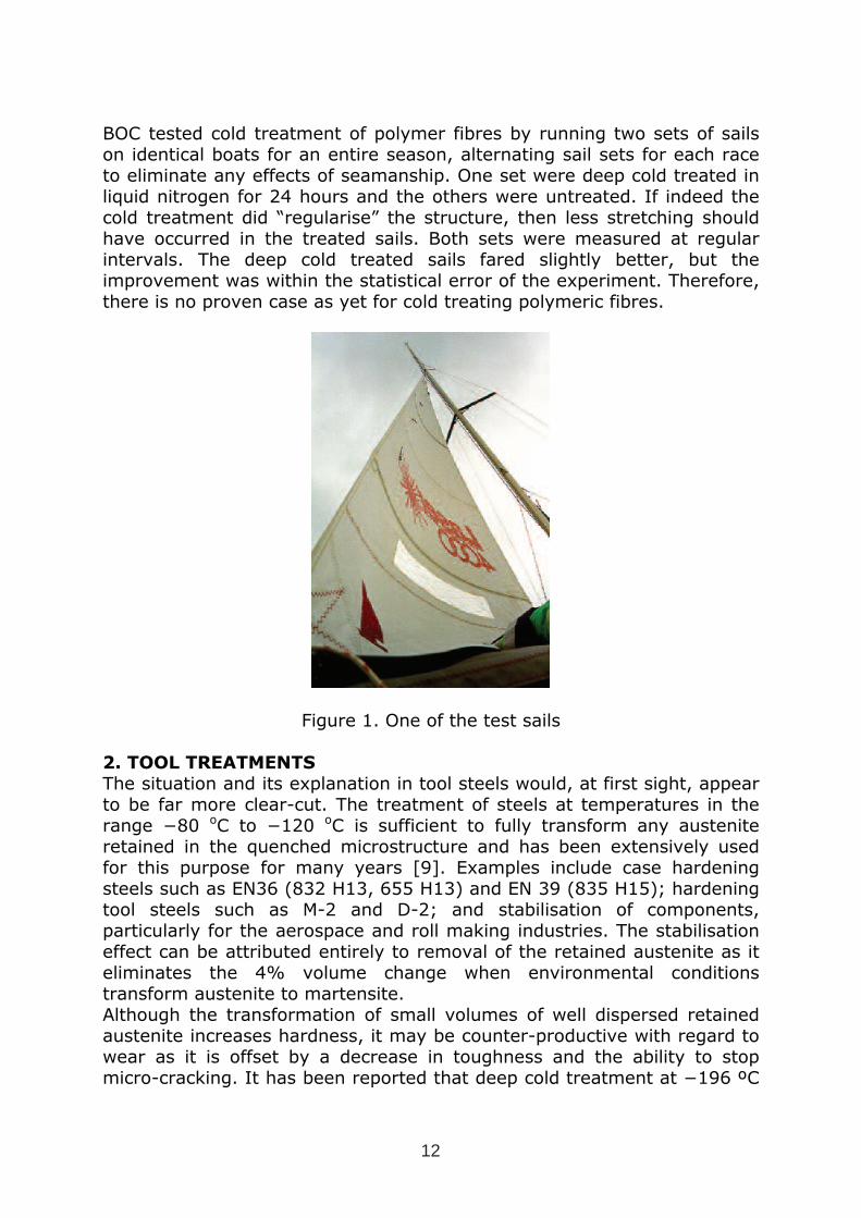
BOC tested cold treatment of polymer fibres by running two sets of sails on identical boats for an entire season, alternating sail sets for each race to eliminate any effects of seamanship. One set were deep cold treated in liquid nitrogen for 24 hours and the others were untreated. If indeed the cold treatment did “regularise” the structure, then less stretching should have occurred in the treated sails. Both sets were measured at regular intervals. The deep cold treated sails fared slightly better, but the improvement was within the statistical error of the experiment. Therefore, there is no proven case as yet for cold treating polymeric fibres.
Figure 1. One of the test sails
2. TOOL TREATMENTS
The situation and its explanation in tool steels would, at first sight, appear to be far more clear-cut. The treatment of steels at temperatures in the range −80 oC to −120 oC is sufficient to fully transform any austenite retained in the quenched microstructure and has been extensively used for this purpose for many years [9]. Examples include case hardening steels such as EN36 (832 H13, 655 H13) and EN 39 (835 H15); hardening tool steels such as M-2 and D-2; and stabilisation of components, particularly for the aerospace and roll making industries. The stabilisation effect can be attributed entirely to removal of the retained austenite as it eliminates the 4% volume change when environmental conditions transform austenite to martensite. Although the transformation of small volumes of well dispersed retained austenite increases hardness, it may be counter-productive with regard to wear as it is offset by a decrease in toughness and the ability to stop micro-cracking. It has been reported that deep cold treatment at −196 ºC
12
(77 °K) combined with different austenitising temperatures, and hence varying the volume of initial retained austenite, can optimise the fracture toughness and hardness for a particular application [10-13]. However, these studies used only short duration deep cold treatment that is known not to optimise wear resistance [2].
3. DEEP COLD FOR WEAR RESISTANCE
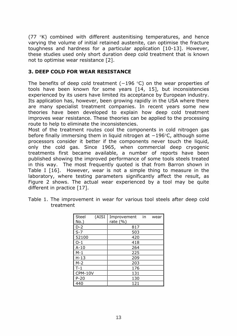
The benefits of deep cold treatment (−196 °C) on the wear properties of tools have been known for some years [14, 15], but inconsistencies experienced by its users have limited its acceptance by European industry. Its application has, however, been growing rapidly in the USA where there are many specialist treatment companies. In recent years some new theories have been developed to explain how deep cold treatment improves wear resistance. These theories can be applied to the processing route to help to eliminate the inconsistencies. Most of the treatment routes cool the components in cold nitrogen gas before finally immersing them in liquid nitrogen at −196°C, although some processors consider it better if the components never touch the liquid, only the cold gas. Since 1965, when commercial deep cryogenic treatments first became available, a number of reports have been published showing the improved performance of some tools steels treated in this way. The most frequently quoted is that from Barron shown in Table I [16]. However, wear is not a simple thing to measure in the laboratory, where testing parameters significantly affect the result, as Figure 2 shows. The actual wear experienced by a tool may be quite different in practice [17].
Table 1. The improvement in wear for various tool steels after deep cold treatment
Steel (AISI No.)
Improvement in wear rate (%)
D-2 817
S-7 503
52100 420
O-1 418
A-10 264
M-1 225
H-13 209
M-2 203
T-1 176
CPM-10V 131
P-20 130
440 121
13
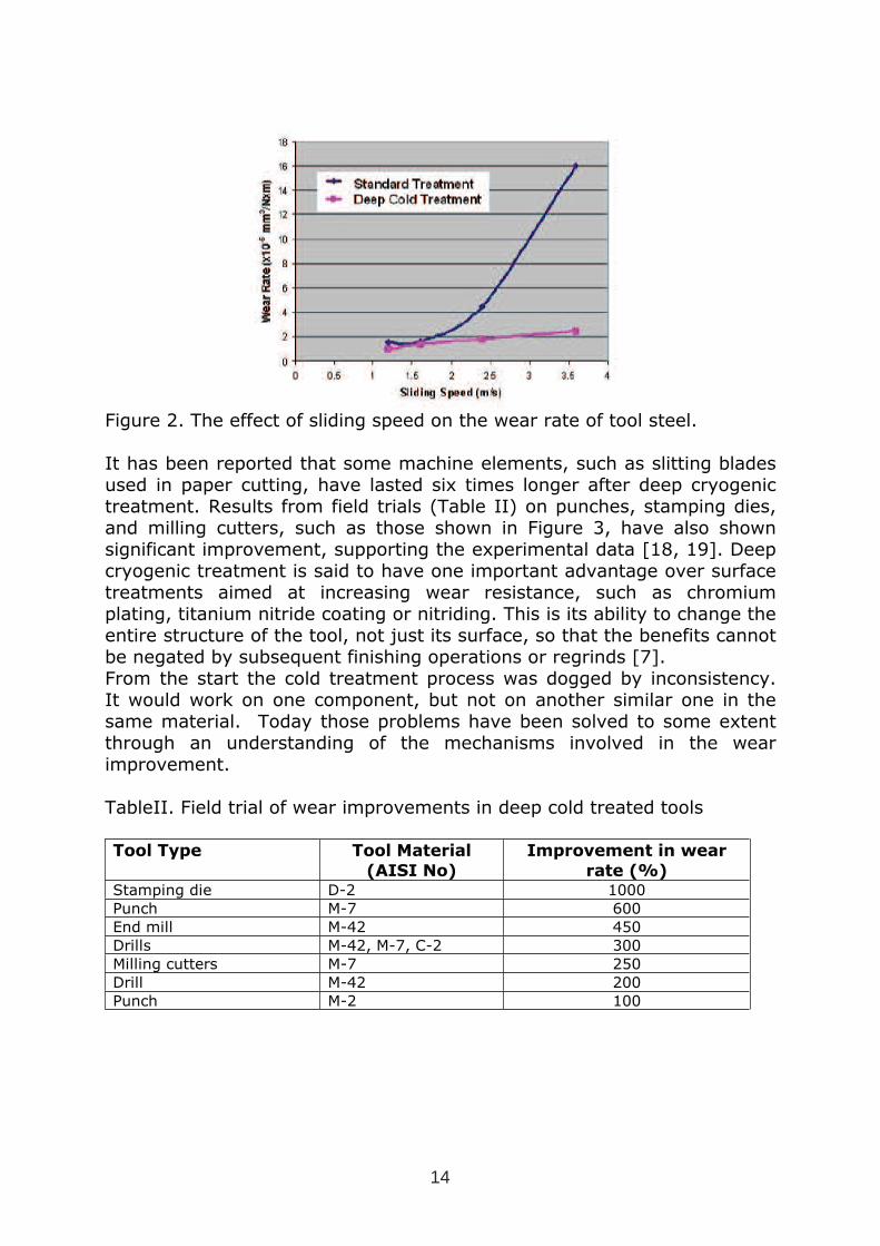
Figure 2. The effect of sliding speed on the wear rate of tool steel.
It has been reported that some machine elements, such as slitting blades used in paper cutting, have lasted six times longer after deep cryogenic treatment. Results from field trials (Table II) on punches, stamping dies, and milling cutters, such as those shown in Figure 3, have also shown significant improvement, supporting the experimental data [18, 19]. Deep cryogenic treatment is said to have one important advantage over surface treatments aimed at increasing wear resistance, such as chromium plating, titanium nitride coating or nitriding. This is its ability to change the entire structure of the tool, not just its surface, so that the benefits cannot be negated by subsequent finishing operations or regrinds [7]. From the start the cold treatment process was dogged by inconsistency. It would work on one component, but not on another similar one in the same material. Today those problems have been solved to some extent through an understanding of the mechanisms involved in the wear improvement.
TableII. Field trial of wear improvements in deep cold treated tools
Tool Type Tool Material
(AISI No)
Improvement in wear
rate (%) Stamping die D-2 1000 Punch M-7 600 End mill M-42 450 Drills M-42, M-7, C-2 300 Milling cutters M-7 250 Drill M-42 200 Punch M-2 100
14
Figure 3. A selection of deep cold treated tools
4. THE MECHANISM OF WEAR RESISTANCE IMPROVEMENT IN
DEEP COLD TREATMENT
There have been several studies of the effect of deep cold on wear and the mechanism that may be giving rise to the improvement [2, 15, 20-25]. Unfortunately some of the papers do not give all the processing parameters and every processing route specified is different. The effects of deep cryogenic processing are seen as occurring in several stages. In the first stage, down to −130 oC, retained austenite is transformed in exactly the same way as in conventional sub-zero treatment, increasing the hardness. However, Meng et al suggest that the lattice parameters of the martensite formed are different from that formed in conventional treatments, which may well account for its subsequent lack of response to extended exposure to deep cold temperatures [25]. As in the conventional treatment, the transformation is not time-dependent [2, 24]. In the second stage, which occurs at deep cryogenic temperatures (typically −196 oC, the temperature of liquid nitrogen), there is a time-dependent decomposition of the primary martensite. This decomposition causes some initial softening but nucleates numerous coherent nano-carbides [23]. During the subsequent tempering operation the fine ε-carbides formed and precipitated at these sites are the reason for the increased wear resistance of the treated tools. It has been shown that the longer the exposure to cryogenic temperatures, the more nano-carbides are formed [24]. It is suggested, however, that it is only the primary martensite that decomposes, and not that with the higher c/a ratio produced by the transformation in the first stage. This mechanism goes some way to explaining the inconsistency of the results. If a component initially has a high retained austenite level then the transformation in the first stage will dramatically increase the hardness, but not necessarily the wear resistance, compared with the original state. If a component has only a low retained austenite level then the carbide formation engendered by the
15
second stage would dramatically increase the wear resistance compared to its original state, but without altering the hardness. It is also possible to deep cold treat after high temperature tempering with less, but still significant, fine ε-carbides precipitation and it has been reported that M2 that has been deep cryogenically treated twice shows further improvement after the second treatment [25]. The “popular” literature contains many references into the need for low cooling rates and accurate cooling curve control down to liquid nitrogen temperatures [26]. This need appears to be driven by the desire of the equipment manufactures to sell expensive equipment capable of such control rather than by any evidence in the “technical” literature. It is however, important to cool and reheat slowly enough to avoid cracking through differential contraction/expansion and the effects of the 4% volume change on transformation of the retained austenite to martensite, but it is not critical to ε-carbide formation. It is often reported that deep cold treatment should follow immediately after quenching, but it has also been suggested that a short warm (60 ºC) ageing after quenching can reduce the tendency to cracking [23]. It has been shown more ε-carbides are produced by a longer deep cold treatment at cryogenic temperatures and, as might be expected, the subsequent wear rate also falls with increasing exposure time [24, 25]. The recommended minimum time at low temperature is 24 hours, however, extended or multiple treatments are known to be beneficial. Tool steels that normally exhibit secondary hardening do not do so after deep cold treatment so they can be tempered at a lower temperature to maintain hardness [24,27]. However, the wear rates are lower when the steel is tempered at its normal tempering temperature because the morphology of the larger carbides is improved.
5. RECOMMENDED PROCESS STEPS
It is not possible to recommend a single process for every tool steel, nor even a single cycle for all tools manufactured from the same steel. Each tool needs to be separately assessed and an individual process route devised for it that will depend on the combination of hardness, toughness and wear resistance required in service. The cryogenic treatment is just one step in that process and must be integrated into the processing route [28]. BOC recommends that tools be treated in specially designed equipment using liquid nitrogen as the refrigerant. The liquid nitrogen is supplied by BOC either via small portable storage containers or static, externally sited, vacuum insulated vessels for larger volumes. The whole process cycle can be automatically controlled for greater consistency and reproducibility. In addition to deep cold capability, some of the units on the market also incorporate a temper/stress relief facility. This releases the heat treatment furnaces for further treatments.
16
Figure 4. A schematic of the recommended processing route .The steps in the processing route for maximum wear resistance in Figure 4 are: 1. Heat to an austenitising temperature that will minimise retained
austenite in the tool steel being treated 2. Hold for the recommended time for the steel 3. Quench at a rate sufficient to give a fully martensitic structure 4. Condition at 60ºC for a maximum of one hour and immediately go to
step 5 5. Cool to liquid nitrogen temperature (−196ºC) at a rate slow enough to
prevent cracking, preferably in a nitrogen atmosphere to avoid condensation
6. Hold at liquid nitrogen temperature for a minimum of 24 hours, preferably in a nitrogen atmosphere to avoid condensation
7. Reheat to room temperature at a rate slow enough to prevent cracking, preferably in a nitrogen atmosphere to avoid condensation
8. Temper at the temperature recommended for the steel being treated.
6. FURTHER IMPROVEMENTS
There is insufficient driving force at liquid nitrogen temperature (−196ºC) to form the nuclei of the ε-carbides in the martensite formed at low temperature [2, 22]. This limits the useful application of the deep cold process to tool steels that have been austenitised at lower temperature to minimise retained austenite formation, but which, however, also minimises hardness. If the driving force were increased by cooling to a lower temperature, then it might be possible to form carbides in the martensite formed at low temperatures, thus maximising performance with a combination of high hardness and fine ε-carbide dispersion. The obvious choice of refrigerant would be liquid helium at −269 ºC (4 ºK). However, it is inevitable that treatment times would be very long as there is little atomic movement at such a low temperature.
17
7. CONCLUSIONS
As part of an optimised heat treatment cycle, deep cold treatment can dramatically improve measured wear by the precipitation of fine ε-carbides in the primary martensite. The transformation of retained austenite to martensite is a minor additional benefit. In many practical uses of tools this increase in measured wear translates into longer tool life.
REFERENCES
1. P Paulin “Mechanism and Applicability of Heat Treating at Cryogenic Temperatures”, Industrial Heating, August 1992, pp22-27
2. Collins, D.N., “Deep cryogenic treatment of tool steels: a review”, Heat Treatment of Metals, 1996, Vol.23, No.2.
3. “Freezing barrels for better accuracy”, Guns & Ammo, April 1996, pp 66-67
4. R T Dohacz, “Rocket Science: adding power and reliability with cryogenics”, Drag Racing USA, August 2003, pp 28-30
5. P Paulin, “Cryo-Rifles: Deep Cryogenic Stress Relief”, Precision Shooting, March 1995, pp 74-76
6. “Deep Freeze, Deep Secret?”, Race & Rally, January, 1996, pp 26-56 7. Paulin, P., “Cold cuts”, Cutting Tool Engineering, Vol.44, No.5, August
1992. 8. R Schiradelly and FJ Diekman, “Cryogenics; the racers edge”, Heat
Treating Progress, November 2001, pp 43-49. 9. Moore, C, “Development of the BOC Ellenite process (cold treatment
of metals with liquid nitrogen), Heat Treatment ’73, The Metals Society,1975, Book No 163 pp 157-161
10. R Mahmudi, HM Ghasemi and HR Faraji, “Effects of cryogenic treatments on the mechanical properties and wear behaviour of high-speed steel M2”, Heat Treatment of Metals, 2000, Vol.27, No.3, pp.69-72
11. V Leskovsek, B Liščić and B Ule, “Some aspects of sub-zero tempering at vacuum heat treatment of HSS”, Proceedings of the 21st Conference 5-8 November 2001 CD ROM, Heat Treating Society
12. V.Leskovsek and B. Ule, “Influence of deep cryogen treatment on microstructure, mechanical properties and dimensional changes in vacuum heat-treated high-speed steel”, Heat Treatment of Metals, 2002, Vol.29,No.3, pp72-76
13. AI Wojcieszynski, “Cryogenic treatment: a mystery or misery of heat treatment”, Proceedings of the 19th Heat Treating Society conference, pp 237-243, 1999
14. Keen, AR, “Cryogenic treatment to improve wear resistance of steel by the “Cryotough” process”, Metals Australasia, August 1982, Vol.14, No.7. 12-12,21
18
15. Reasbeck, RB, “Improved tool life by the Cryotough treatment”, Metallurgia, April 1989, Vol.56, No.4, pp 178-179
16. RF Barron, “Cryogenic treatment of metals to improve wear resistance", Cryogenics, Vol.22, No.8. pp 409-413, 1982
17. RC Lasky, “The effects of cryotempering on tool steels”, http://www.nitrofreeze.com/toolsteels.html
18. http://www.cryoeng.com/images/Field%20Test%20Results.pdf 19. http://www.diversifiedcryogenics.com/testresults.htm 20. L Alexandru, G Coman and V Bulancea, “The change of the
substructure elements and the redistribution of the alloying elements by means of cryotreatments in alloy tool steels”, Proceedings of the 5th International Congress on Heat Treatment of Materials, Vol.2, pp.901-908, 1986
21. L Alexandru, C Baciu and G Ailincai, “Contributions on the study of the increase of durability of the high-alloyed tool steels by thermal treatments at cryogenic temperatures”, Memoires et Etudes Sci. Rev. Metall. 1990, Vol.87, No.6, pp.383-339
22. Dormer, J., “The cryogenic treatment of tool steels”, Thesis, National University of Ireland, University College Dublin, August 1994.
23. F Meng, K Tagashira, R Azuma amd H Sohma, “Role of eta-carbide precipitation’s in the wear resistance improvements of Fe-12-Cr-Mo-V-1.4C tool steel by cryogenic treatment”, ISIJ International, Vol.34, No.2, pp 205-210, 1994
24. DN Collins and J Dormer, “Deep cryogenic treatment of a D2 cold work tool steel”. Heat Treatment of Metals, Vol.24, No.3, pp 71-74, 1997
25. D Yun, L Xiaoping and X Hongshen, “Deep cryogenic treatment of high speed steel and its mechanism”, Heat Treatment of Metals, Vol.25, No.3, pp 55-59, 1998
26. DL Hallum, “Cryogenic tempering delivers better cutting tool durability”, American Machinist, May, 1996, pp140-141
27. DN Collins and J Dormer, “Deep cryogenic treatment of an ASP 23 high speed steel”, Proceedings of the 18th Heat Treating Society conference, pp.255-258, 1998
28. DN Collins and G O'Rourke, “The response of tool steels to deep cryogenic treatment: effect of alloying elements”, Proceedings of the 18th Heat Treating Society conference, pp.229-247, 1998
29. http://www.cryogenic.co.nz/index.cfm?fuseaction=dsp_content&page_id=23
19

WEAR BEHAVIOUR OF DEEP CRYOGENIC TREATED
HIGH SPEED STEELS
M. Kalin1, *
, V. Leskovšek 2, J. Vižintin
1
1Center for Tribology and Technical Diagnistics, University of Ljubljana, Bogišičeva 8, 1000 Ljubljana, Slovenia (* [email protected] )2Institute of Metals and Technology, Lepi pot 11, 1000 Ljubljana, Slovenia
ABSTRACT
Tools for the cold-working applications are typically made from the high-speed steels. However, due to wear and plastic deformation their performance in several applications is not adequate and should be further improved. By using appropriate combination of vacuum heat-treatment in conjunction with a deep-cryogenic treatment (duplex treatment) the microstructure of high-speed steel matrix can be substantially changed and the hardness andfracture toughness can be modified and optimised. In the present work we have investigated the effect of four different tempering temperatures of vacuum and cryogenic treated ESR AISIM2 high speed steel on the resulting combinations of microstructure, hardness and toughness and their effect on the wear mechanisms at different loads. The results showed that at relatively high loads the different treatments resulted in an order of magnitude difference of wear resistance, while at low loads the selected treatments were efficient enough to keep the wear within the mild wear regime and small variations between the samples. However, the overall wear transition did not occur at any load used or any sample treatment, although some small differences in wear mechanisms can be seen, primarily depending on the fracture toughness of the samples.
Key words: cryogenic and duplex treatment, high speed steel, wear, friction, microstructure
1. INTRODUCTION
The wear resistance of high-speed steels is largely influenced by the microstructure, which consequently affects the hardness and fracture toughness of the material. In hardened andtempered condition, the important constituents of high-speed steel are the matrix, i.e. tempered martensite and retained austenite, and un-dissolved eutectic carbide particles. These phases importantly affect the wear-resistance of the steel. However, when applying the deep-cryogenic treatment followed by single tempering, the matrix of high-speed steel can be additionally tailored [1-4]. By using appropriate combination of vacuum heat-treatment inconjunction with a deep-cryogenic treatment the microstructure of high-speed steel can be substantially modified, which consequently affect the ratio between the hardness and fracture toughness. Moreover, a semi-empirical equation (Eq.1) was recently derived for the HSS [5], providing the relation between the fracture toughness KIc, Rockwell-C hardness HRC and
21
1 INTERNATIONAL CONFERENCE ON HEAT TREATMENT
AND SURFACE ENGINEERING OF TOOLS AND DIES
st
Pula, Croatia 08 - 11 June, 2005,
IFHTSE 2005
quantified microstructural parameters. Several microstructural parameters, like mean distance between undissolved eutectic carbide particles dp, volume fractions of undissolved eutectic carbides fcarb, volume fractions of retained austenite faust and some other material properties like modulus of elasticity and hardness were considered. The resulting calculated fracture toughness agreed very well with the experimental results [6], which confirmed a strong dependence between microstructure, hardness and fracture toughness [7].
( ) ( )
+⋅⋅⋅⋅
−⋅=
−
aust6
1
carbpIc f1fdE53HRc
HRc1.363K (Eq. 1)
In our previous study, we have investigated the effect of deep cryogenic treatment on the wearand friction behaviour of high-speed steel by comparing the conventionally treated samples and the additionally deep cryogenic treated samples. The deep cryogenic treated samples withan optimal ratio of the above mentioned parameters showed significantly better results [8]. Inthe present work we present the effect of deep cryogenic treatment of vacuum hardened ESR M2 high speed steel (tempered at four different temperatures, and initially austentized) at three different loads, to cover the load range important from the application point of view. The effect of resulting hardness, toughness and microstructure on the acting wear mechanismsin reciprocating sliding tests were investigated.
2. EXPERIMENTAL
2.1 Material characterisation and duplex treatment
Investigated high-speed steel M2 was delivered in the shape of rolled, soft annealed bar of φ20 mm x 4000 mm. The bar was cut into metallographic samples of φ 20x9 mm. All the samples were vacuum heat treated in a horizontal vacuum furnace with uniform high-pressure gas quenching using N2 at a pressure of 5 bars. After the last preheat the specimens were heated to the austenitizing temperature of 1230 °C, soaked for 2 minutes, and gas quenched to25 °C with the cooling parameter λ800-500 = 0,55. The specimens were then removed from the furnace for a subsequent deep-cryogenic treatment, followed by a single tempering cycle for one hour at four different and carefully selected temperatures, i.e. 500, 540, 550, and 600oC to obtain specific hardness and toughness properties. The deep cryogenic treatment of metallographic specimens was performed by a controlled immersion of individual test specimens in liquid nitrogen (-196oC). After equalization of the temperature (when the liquid N2 ceased boiling) the specimens were soaked in liquid nitrogen for one hour. After the duplex treatment of the samples, they were ground and polished for further analyses.The resulting Ra roughness of all samples was better than 0.01 µm. The Rockwell-C hardness was measured on the metallographic specimens using a Wilson 4JR hardness tester. The microstructures of the investigated metallographic specimens were assessed as described in detail elsewhere [9] and the fracture toughness was calculated using Eq. (1) [5]. The results are presented in Table I.
Table I. Results of Rockwell hardness and fracture toughness for investigated samples
Samples at differenttempering temperatures
Rockwell-C hardness( HRc )
Fracture toughness KIC
( MPa m1/2 )A-500 65.2 8.5 B-540 65.8 8.0C-550 65.5 8.8D-600 64.4 9.5
22
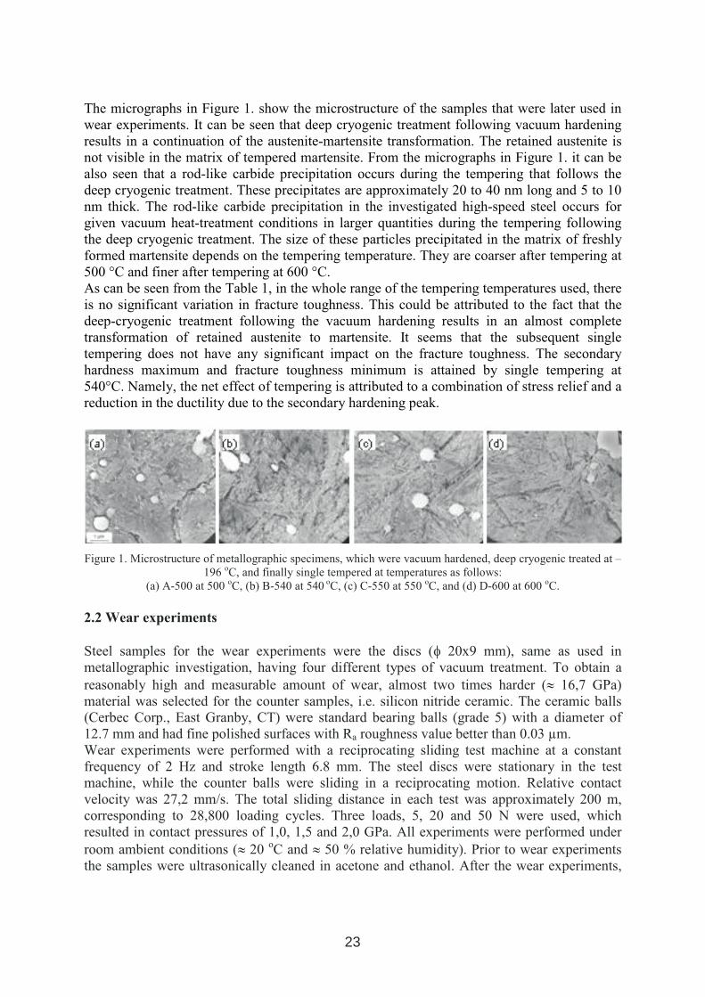
The micrographs in Figure 1. show the microstructure of the samples that were later used in wear experiments. It can be seen that deep cryogenic treatment following vacuum hardening results in a continuation of the austenite-martensite transformation. The retained austenite is not visible in the matrix of tempered martensite. From the micrographs in Figure 1. it can be also seen that a rod-like carbide precipitation occurs during the tempering that follows the deep cryogenic treatment. These precipitates are approximately 20 to 40 nm long and 5 to 10 nm thick. The rod-like carbide precipitation in the investigated high-speed steel occurs for given vacuum heat-treatment conditions in larger quantities during the tempering followingthe deep cryogenic treatment. The size of these particles precipitated in the matrix of freshly formed martensite depends on the tempering temperature. They are coarser after tempering at 500 °C and finer after tempering at 600 °C. As can be seen from the Table 1, in the whole range of the tempering temperatures used, there is no significant variation in fracture toughness. This could be attributed to the fact that the deep-cryogenic treatment following the vacuum hardening results in an almost complete transformation of retained austenite to martensite. It seems that the subsequent single tempering does not have any significant impact on the fracture toughness. The secondary hardness maximum and fracture toughness minimum is attained by single tempering at 540°C. Namely, the net effect of tempering is attributed to a combination of stress relief and a reduction in the ductility due to the secondary hardening peak.
Figure 1. Microstructure of metallographic specimens, which were vacuum hardened, deep cryogenic treated at –196 oC, and finally single tempered at temperatures as follows:
(a) A-500 at 500 oC, (b) B-540 at 540 oC, (c) C-550 at 550 oC, and (d) D-600 at 600 oC.
2.2 Wear experiments
Steel samples for the wear experiments were the discs (φ 20x9 mm), same as used inmetallographic investigation, having four different types of vacuum treatment. To obtain a reasonably high and measurable amount of wear, almost two times harder (≈ 16,7 GPa) material was selected for the counter samples, i.e. silicon nitride ceramic. The ceramic balls (Cerbec Corp., East Granby, CT) were standard bearing balls (grade 5) with a diameter of 12.7 mm and had fine polished surfaces with Ra roughness value better than 0.03 µm. Wear experiments were performed with a reciprocating sliding test machine at a constant frequency of 2 Hz and stroke length 6.8 mm. The steel discs were stationary in the test machine, while the counter balls were sliding in a reciprocating motion. Relative contact velocity was 27,2 mm/s. The total sliding distance in each test was approximately 200 m,corresponding to 28,800 loading cycles. Three loads, 5, 20 and 50 N were used, whichresulted in contact pressures of 1,0, 1,5 and 2,0 GPa. All experiments were performed under room ambient conditions (≈ 20 oC and ≈ 50 % relative humidity). Prior to wear experiments the samples were ultrasonically cleaned in acetone and ethanol. After the wear experiments,
23
further cleaning and profilometric analyses, the discs were sputter coated with gold andexamined by Scanning Electron Microscopy (JEOL JSM-T330A, Tokyo, Japan).
3. RESULTS AND DISCUSION
3.1. Wear
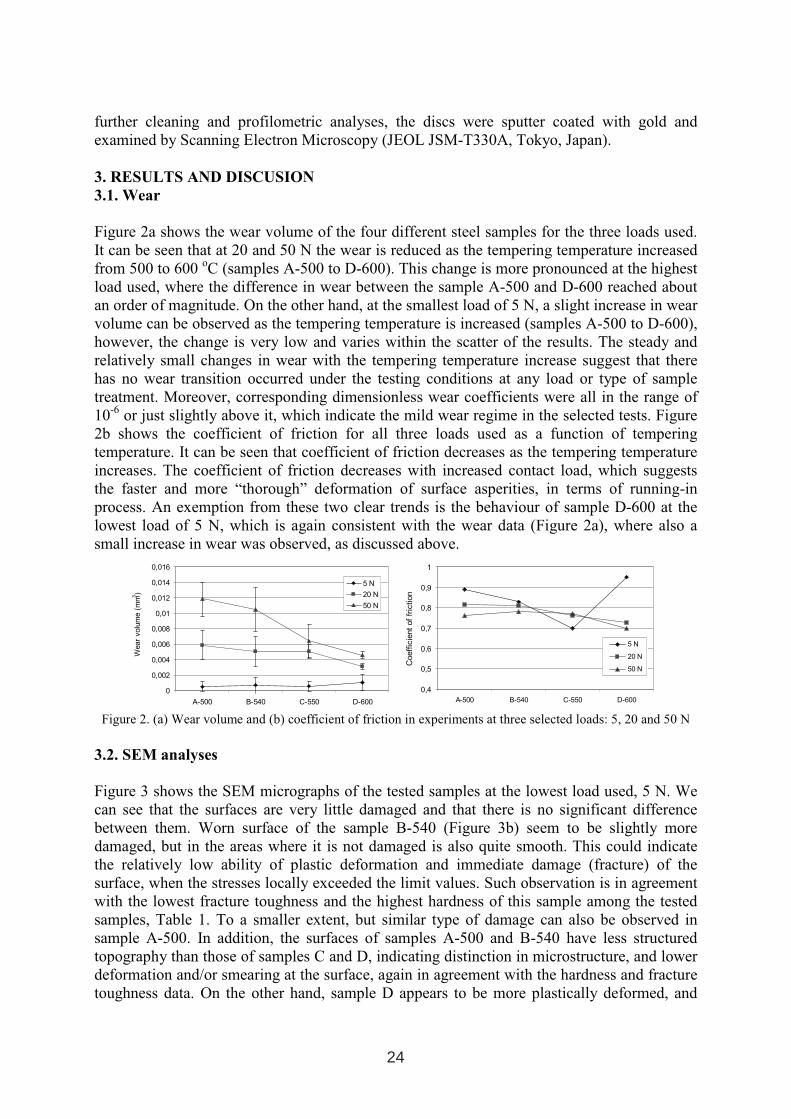
Figure 2a shows the wear volume of the four different steel samples for the three loads used. It can be seen that at 20 and 50 N the wear is reduced as the tempering temperature increasedfrom 500 to 600 oC (samples A-500 to D-600). This change is more pronounced at the highest load used, where the difference in wear between the sample A-500 and D-600 reached about an order of magnitude. On the other hand, at the smallest load of 5 N, a slight increase in wearvolume can be observed as the tempering temperature is increased (samples A-500 to D-600), however, the change is very low and varies within the scatter of the results. The steady and relatively small changes in wear with the tempering temperature increase suggest that there has no wear transition occurred under the testing conditions at any load or type of sample treatment. Moreover, corresponding dimensionless wear coefficients were all in the range of 10-6 or just slightly above it, which indicate the mild wear regime in the selected tests. Figure 2b shows the coefficient of friction for all three loads used as a function of temperingtemperature. It can be seen that coefficient of friction decreases as the tempering temperature increases. The coefficient of friction decreases with increased contact load, which suggests the faster and more “thorough” deformation of surface asperities, in terms of running-inprocess. An exemption from these two clear trends is the behaviour of sample D-600 at the lowest load of 5 N, which is again consistent with the wear data (Figure 2a), where also a small increase in wear was observed, as discussed above.
0
0,002
0,004
0,006
0,008
0,01
0,012
0,014
0,016
A-500 B-540 C-550 D-600
Wear
volu
me
(mm
3)
5 N
20 N
50 N
0,4
0,5
0,6
0,7
0,8
0,9
1
A-500 B-540 C-550 D-600
Coeff
icie
nt
of
fric
tion
5 N
20 N
50 N
Figure 2. (a) Wear volume and (b) coefficient of friction in experiments at three selected loads: 5, 20 and 50 N
3.2. SEM analyses
Figure 3 shows the SEM micrographs of the tested samples at the lowest load used, 5 N. We can see that the surfaces are very little damaged and that there is no significant difference between them. Worn surface of the sample B-540 (Figure 3b) seem to be slightly more damaged, but in the areas where it is not damaged is also quite smooth. This could indicate the relatively low ability of plastic deformation and immediate damage (fracture) of the surface, when the stresses locally exceeded the limit values. Such observation is in agreement with the lowest fracture toughness and the highest hardness of this sample among the tested samples, Table 1. To a smaller extent, but similar type of damage can also be observed insample A-500. In addition, the surfaces of samples A-500 and B-540 have less structured topography than those of samples C and D, indicating distinction in microstructure, and lower deformation and/or smearing at the surface, again in agreement with the hardness and fracture toughness data. On the other hand, sample D appears to be more plastically deformed, and
24
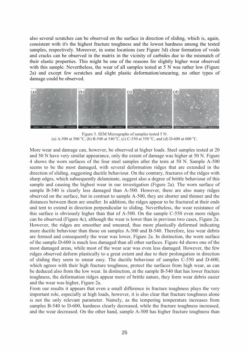
also several scratches can be observed on the surface in direction of sliding, which is, again, consistent with it's the highest fracture toughness and the lowest hardness among the tested samples, respectively. Moreover, in some locations (see Figure 3d) clear formation of voids and cracks can be observed in the matrix in the vicinity of carbides due to the mismatch of their elastic properties. This might be one of the reasons for slightly higher wear observed with this sample. Nevertheless, the wear of all samples tested at 5 N was rather low (Figure 2a) and except few scratches and slight plastic deformation/smearing, no other types of damage could be observed.
Figure 3. SEM Micrographs of samples tested 5 N: (a) A-500 at 500 oC, (b) B-540 at 540 oC, (c) C-550 at 550 oC, and (d) D-600 at 600 oC.
More wear and damage can, however, be observed at higher loads. Steel samples tested at 20 and 50 N have very similar appearance, only the extent of damage was higher at 50 N. Figure 4 shows the worn surfaces of the four steel samples after the tests at 50 N. Sample A-500 seems to be the most damaged, with several deformation ridges that are extended in the direction of sliding, suggesting ductile behaviour. On the contrary, fractures of the ridges withsharp edges, which subsequently delaminate, suggest also a degree of brittle behaviour of this sample and causing the highest wear in our investigation (Figure 2a). The worn surface of sample B-540 is clearly less damaged than A-500. However, there are also many ridges observed on the surface, but in contrast to sample A-500, they are shorter and thinner and the distances between them are smaller. In addition, the ridges appear to be fractured at their ends and tent to extend in direction perpendicular to sliding. Nevertheless, the wear resistance of this surface is obviously higher than that of A-500. On the sample C-550 even more ridges can be observed (Figure 4c), although the wear is lower than in previous two cases, Figure 2a.However, the ridges are smoother and smeared, thus more plastically deformed indicating more ductile behaviour than those on samples A-500 and B-540. Therefore, less wear debris are formed and consequently the wear was lower, Figure 2a. In distinction, the worn surface of the sample D-600 is much less damaged than all other surfaces. Figure 4d shows one of the most damaged areas, while most of the wear scar was even less damaged. However, the few ridges observed deform plastically to a great extent and due to their prolongation in directionof sliding they seem to smear easy. The ductile behaviour of samples C-550 and D-600,which agrees with their high fracture toughness, protect the surfaces from high wear, as can be deduced also from the low wear. In distinction, at the sample B-540 that has lower fracture toughness, the deformation ridges appear more of brittle nature, they form wear debris easier and the wear was higher, Figure 2a. From our results it appears that even a small difference in fracture toughness plays the very important role, especially at high loads, however, it is also clear that fracture toughness alone is not the only relevant parameter. Namely, as the tempering temperature increases from samples B-540 to D-600, hardness clearly decreased, while the fracture toughness increased,and the wear decreased. On the other hand, sample A-500 has higher fracture toughness than
25
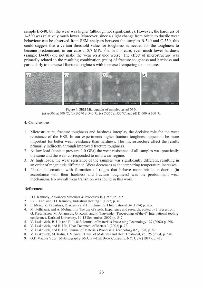
sample B-540, but the wear was higher (although not significantly). However, the hardness of A-500 was relatively much lower. Moreover, since a slight change from brittle to ductile wear behaviour can be observed from SEM analyses between the samples B-540 and C-550, this could suggest that a certain threshold value for toughness is needed for the toughness to become predominant; in our case at 8,7 MPa √m. In this case, even much lower hardness (sample D-600) did not make the wear resistance worse. The effect of microstructure was primarily related to the resulting combination (ratio) of fracture toughness and hardness andparticularly to increased fracture toughness with increased tempering temperature.
Figure 4. SEM Micrographs of samples tested 50 N: (a) A-500 at 500 oC, (b) B-540 at 540 oC, (c) C-550 at 550 oC, and (d) D-600 at 600 oC.
4. Conclusions
1. Microstructure, fracture toughness and hardness interplay the decisive role for the wear resistance of the HSS. In our experiments higher fracture toughness appear to be more important for better wear resistance than hardness. The microstructure affect the results primarily indirectly through improved fracture toughness.
2. At low load (contact pressure 1.0 GPa) the wear resistance of all samples was practically the same and the wear corresponded to mild wear regime.
3. At high loads, the wear resistance of the samples was significantly different, resulting in an order of magnitude difference. Wear decreases as the tempering temperature increases.
4. Plastic deformation with formation of ridges that behave more brittle or ductile (in accordance with their hardness and fracture toughness) was the predominant wear mechanism. No overall wear transition was found in this work.
References
1. D.J. Kamody, Advanced Materials & Processes 10 (1998) p. 215. 2. P.-L. Yen, and D.J. Kamody, Industrial Heating 1 (1997) p. 40. 3. F. Meng, K. Tagashira, R. Azuma and H. Sohma, ISIJ International 34 (1994) p. 205. 4. M. Pellizzari, and A. Molinari, in The use of steels: Experience and research, edited by J: Bergstrom,
G. Fredriksson, M. Johansson, O. Kotik, and F. Thuvander (Proceedings of the 6th International tooling conference, Karlstad University, 10-13 September, 2002) p. 547.
5. V. Leskovšek, B. Ule and B. Liščić, Journal of Materials Processing Technology 127 (2002) p. 298. 6. V. Leskovšek, and B. Ule, Heat Treatment of Metals 3 (2002) p. 72. 7. V. Leskovšek, and B. Ule, Journal of Materials Processing Technology 82 (1998) p. 89. 8. V. Leskovšek, M. Kalin, J. Vižintin, Trans. of Materials and Heat Treatment, vol. 25 (2004) p. 540. 9. G.F. Vander Voort, Metallography; McGraw-Hill Book Company, NY, USA (1984), p. 410.
26
IMPROVING TOOL PRODUCT PERFORMANCE THOUGH THE USE
OF INTENSIVE QUENCHING PROCESSES
M.A. Aronov, J.A. Powell and N.I. Kobasko IQ Technologies IncAkron, Ohio, USA
ABSTRACT
The intensive quenching (IQ) method is an innovative thermal process for hardening steel parts. In contrast to conventional quenching in oil or polymer, the IQ process is an environmentally friendly process conducted in highly agitated plain water. One of the major benefits of the IQ technique is the development of high, beneficial residual compressive stresses in the part surface layer during quenching. The IQ process is interrupted at the computer-calculated time when residual surface compressive stresses reach their maximum value. Residual surface compressive stresses improve part performance characteristics (strength, fatigue and wear resistance, service life, etc.). The paper describes applications of the IQ process to a variety of tool products made of shock-resistance cold work AISI S5 steel, high-speed M2 steel, 52100 steel and others. The paper describes intensive quenching equipment used for IQ demonstration studies.
Key words: Intensive quenching, tool products, residual surface compressive stresses,service life, and intensive quenching equipment.
1. INTRODUCTION
In 1983, authors [1, 2] conducted a computer simulation study on the effect of the coolingrate during quenching on residual surface stresses in the part. The results of calculations performed from conventional quenching in oil confirmed that the higher the cooling rate during quenching, the greater the residual surface tensile stresses in the part. However, the results of calculations showed that when quenching parts intensively (with a much higher heat extraction rate than in oil) the residual compressive stresses develop in the part surface layer. Table I presents the data on residual stress conditions obtained for different Bi numbers [1, 2]. The Bi number is equal to h⋅R/λ, where h is a heat transfer coefficient on the part surface, R is a part dimension characteristic (for example, a radius for a cylindrical part), andλ is the part material thermal conductivity. Thus, for a given part, the Bi number characterizesthe heat extraction rate. As seen from the table, for Bi numbers below 10 (that is a range for conventional quenching), the residual surface stresses are tensile.
1 INTERNATIONAL CONFERENCE ON HEAT TREATMENT
AND SURFACE ENGINEERING OF TOOLS AND DIES
st
Pula, Croatia 08 - 11 June, 2005,
IFHTSE 2005
27
For Bi numbers exceeding 20 (for intensive quenching conditions), there are residual surface compressive stresses and they are more compressive with the increase of the Bi number. The computer simulations showed also that this fact is correct even for through hardened parts. However, at a time of conducting this study, the heat-treating community did not accept these results. This is mainly because the findings presented in [1, 2] contradicted accepted heat-treating knowledge and practice and because of the lack of experimental data supporting the results.
Table I. Hoop residual stresses at the surface of steel parts vs. Biot number Bi
Biot Number Bi 0 2 5 10 20 40 80Hoop residual stresses, MPa 0 + 300 + 400 +200 - 30 - 280 - 630
Over the last several years, IQ Technologies Inc. has conducted a numerous experimental IQ studies of part residual stress conditions after intensive quenching. We considered a variety ofsteel parts made of different steels. This paper summarizes these results.
2. INTENSIVE QUENCHING EQUIPMENT USED FOR IQ DEMONSTRATION
STUDIES
For IQ trials, we used two types of IQ equipment: a) a pre-production high-velocity single-part quenching IQ system where we quench parts one-by-one out of a neutral salt bathfurnace, and b) production batch type IQ units where we quenched parts in batches in an IQ water tank out of an atmosphere furnace. The pre-production high-velocity IQ system was specifically designed for the implementation of a so-called IQ-3 quenching process [5]. Whenapplying the IQ-3 quenching technique, the water flow velocity along the surface of the part being quenched is so high and the convection heat transfer is so great that any boilingprocesses (both film boiling and nucleate boiling) are fully eliminated. The convection heat transfer prevails from the very beginning of the quench. Therefore, the IQ-3 process is alsocalled “direct convection cooling.” The system is able to provide optimum IQ-3 quenchingconditions to a variety of steel products. Figure 1 presents a schematic of the high-velocity IQ system. The IQ system works as follows. Initially, the IQ system is at an idle condition: the pump, 2, is “ON” pushing the water from the tank, 1, through the 3-way valve, 3, and a bypass pipe, 10, back to the tank. The loading table, 7, with an attached fixture is in the lower position. A hot part to be quenched is put into the lower section of the fixture that is attached to the loading table. The air cylinders, 8, move the loading table, 7, with the part upward into stationary upper sectionof the fixture. The upper section of the fixture (not shown) is a pipe that is attached to the tube, 11. The lower end of the upper fixture has a flange with an attached rubber ring. When the loading table is at the upper position, the rubber ring is held against it providing sealing ofthe system. As soon as the part is in position within the upper section of the fixture, the three-way valve, 3, switches the water flow from the idle position into the piping, 4, for intensive quenching of the part. After the quench is completed, the 3-way valve, 3, switches the water flow back to the bypass pipe, 10, and the air cylinders lower the loading table with the part.Note that when the system is in quenching mode, the water flow may be split in two flows or streams after passing the 3-way valve. A shut-off valve, 5, and a flow meter, 6 control each water flow path. The reason for this is that when quenching bearing rings it is necessary tocontrol two water flows: one along the ID surface and along the ring OD surface. The high-
28
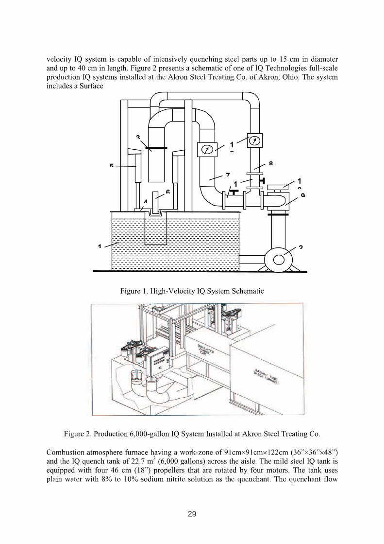
velocity IQ system is capable of intensively quenching steel parts up to 15 cm in diameter and up to 40 cm in length. Figure 2 presents a schematic of one of IQ Technologies full-scale production IQ systems installed at the Akron Steel Treating Co. of Akron, Ohio. The system includes a Surface
Figure 1. High-Velocity IQ System Schematic
Figure 2. Production 6,000-gallon IQ System Installed at Akron Steel Treating Co.
Combustion atmosphere furnace having a work-zone of 91cm×91cm×122cm (36”×36”×48”)and the IQ quench tank of 22.7 m3 (6,000 gallons) across the aisle. The mild steel IQ tank is equipped with four 46 cm (18”) propellers that are rotated by four motors. The tank uses plain water with 8% to 10% sodium nitrite solution as the quenchant. The quenchant flow
1 2
3
4
5
6
7
8
9
10
11
12
29
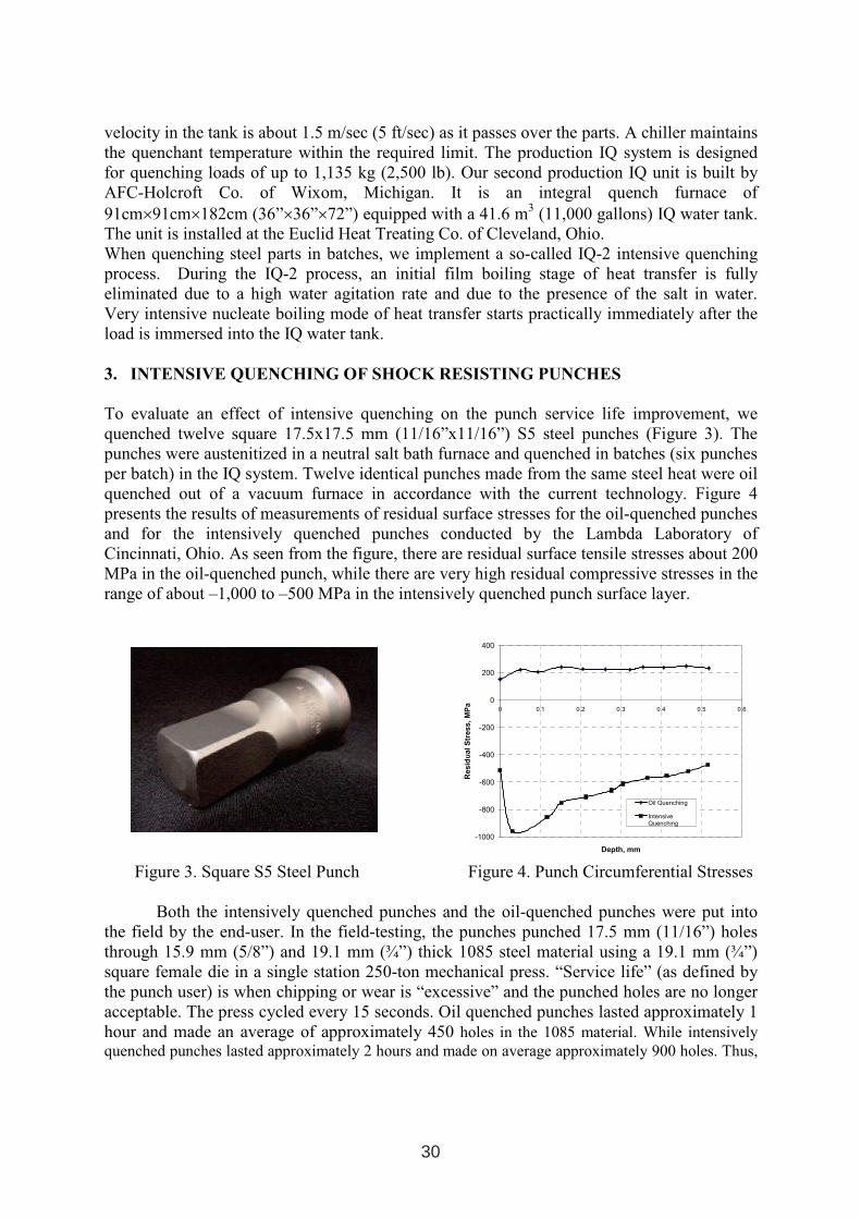
velocity in the tank is about 1.5 m/sec (5 ft/sec) as it passes over the parts. A chiller maintainsthe quenchant temperature within the required limit. The production IQ system is designed for quenching loads of up to 1,135 kg (2,500 lb). Our second production IQ unit is built by AFC-Holcroft Co. of Wixom, Michigan. It is an integral quench furnace of 91cm×91cm×182cm (36”×36”×72”) equipped with a 41.6 m3 (11,000 gallons) IQ water tank. The unit is installed at the Euclid Heat Treating Co. of Cleveland, Ohio. When quenching steel parts in batches, we implement a so-called IQ-2 intensive quenching process. During the IQ-2 process, an initial film boiling stage of heat transfer is fully eliminated due to a high water agitation rate and due to the presence of the salt in water.Very intensive nucleate boiling mode of heat transfer starts practically immediately after the load is immersed into the IQ water tank.
3. INTENSIVE QUENCHING OF SHOCK RESISTING PUNCHES
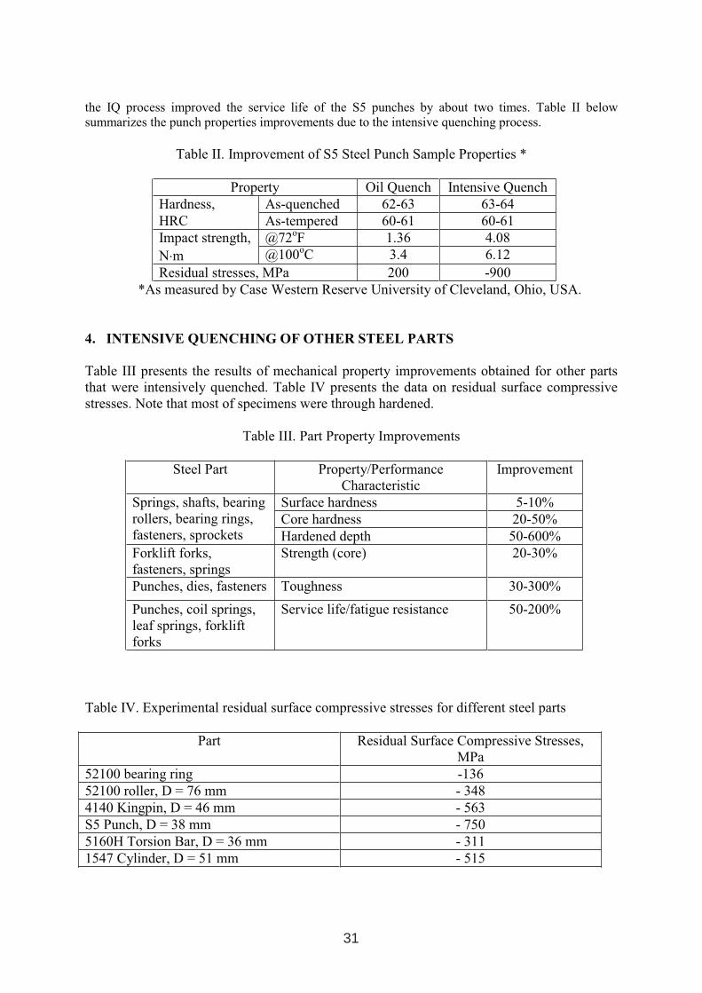
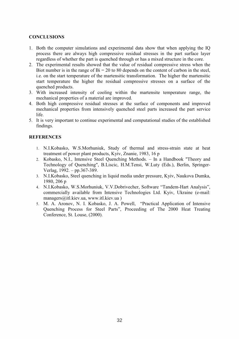
To evaluate an effect of intensive quenching on the punch service life improvement, we quenched twelve square 17.5x17.5 mm (11/16”x11/16”) S5 steel punches (Figure 3). The punches were austenitized in a neutral salt bath furnace and quenched in batches (six punches per batch) in the IQ system. Twelve identical punches made from the same steel heat were oil quenched out of a vacuum furnace in accordance with the current technology. Figure 4presents the results of measurements of residual surface stresses for the oil-quenched punches and for the intensively quenched punches conducted by the Lambda Laboratory of Cincinnati, Ohio. As seen from the figure, there are residual surface tensile stresses about 200 MPa in the oil-quenched punch, while there are very high residual compressive stresses in the range of about –1,000 to –500 MPa in the intensively quenched punch surface layer.
Figure 3. Square S5 Steel Punch Figure 4. Punch Circumferential Stresses
Both the intensively quenched punches and the oil-quenched punches were put into the field by the end-user. In the field-testing, the punches punched 17.5 mm (11/16”) holes through 15.9 mm (5/8”) and 19.1 mm (¾”) thick 1085 steel material using a 19.1 mm (¾”) square female die in a single station 250-ton mechanical press. “Service life” (as defined by the punch user) is when chipping or wear is “excessive” and the punched holes are no longer acceptable. The press cycled every 15 seconds. Oil quenched punches lasted approximately 1hour and made an average of approximately 450 holes in the 1085 material. While intensively quenched punches lasted approximately 2 hours and made on average approximately 900 holes. Thus,
-1000
-800
-600
-400
-200
0
200
400
0 0.1 0.2 0.3 0.4 0.5 0.6
Depth, mm
Resid
ualS
tress,M
Pa
Oil Quenching
IntensiveQuenching
30
the IQ process improved the service life of the S5 punches by about two times. Table II below summarizes the punch properties improvements due to the intensive quenching process.
Table II. Improvement of S5 Steel Punch Sample Properties *
Property Oil Quench Intensive Quench Hardness, As-quenched 62-63 63-64 HRC As-tempered 60-61 60-61 Impact strength, @72oF 1.36 4.08N⋅m @100oC 3.4 6.12Residual stresses, MPa 200 -900
*As measured by Case Western Reserve University of Cleveland, Ohio, USA.
4. INTENSIVE QUENCHING OF OTHER STEEL PARTS
Table III presents the results of mechanical property improvements obtained for other parts that were intensively quenched. Table IV presents the data on residual surface compressive stresses. Note that most of specimens were through hardened.
Table III. Part Property Improvements
Steel Part Property/PerformanceCharacteristic
Improvement
Surface hardness 5-10% Core hardness 20-50%
Springs, shafts, bearingrollers, bearing rings, fasteners, sprockets Hardened depth 50-600% Forklift forks, fasteners, springs
Strength (core) 20-30%
Punches, dies, fasteners Toughness 30-300%
Punches, coil springs, leaf springs, forkliftforks
Service life/fatigue resistance 50-200%
Table IV. Experimental residual surface compressive stresses for different steel parts
Part Residual Surface Compressive Stresses, MPa
52100 bearing ring -136 52100 roller, D = 76 mm - 348 4140 Kingpin, D = 46 mm - 563 S5 Punch, D = 38 mm - 750 5160H Torsion Bar, D = 36 mm - 311 1547 Cylinder, D = 51 mm - 515
31
CONCLUSIONS
1. Both the computer simulations and experimental data show that when applying the IQ process there are always high compressive residual stresses in the part surface layer regardless of whether the part is quenched through or has a mixed structure in the core.
2. The experimental results showed that the value of residual compressive stress when the Biot number is in the range of Bi = 20 to 80 depends on the content of carbon in the steel, i.e. on the start temperature of the martensitic transformation. The higher the martensitic start temperature the higher the residual compressive stresses on a surface of the quenched products.
3. With increased intensity of cooling within the martensite temperature range, the mechanical properties of a material are improved.
4. Both high compressive residual stresses at the surface of components and improved mechanical properties from intensively quenched steel parts increased the part service life.
5. It is very important to continue experimental and computational studies of the established findings.
REFERENCES
1. N.I.Kobasko, W.S.Morhuniuk, Study of thermal and stress-strain state at heat treatment of power plant products, Kyiv, Znanie, 1983, 16 p
2. Kobasko, N.I., Intensive Steel Quenching Methods. – In a Handbook "Theory and Technology of Quenching", B.Liscic, H.M.Tensi, W.Luty (Eds.), Berlin, Springer-Verlag, 1992. – pp.367-389.
3. N.I.Kobasko, Steel quenching in liquid media under pressure, Kyiv, Naukova Dumka, 1980, 206 p
4. N.I.Kobasko, W.S.Morhuniuk, V.V.Dobrivecher, Software “Tandem-Hart Analysis”,commercially available from Intensive Technologies Ltd. Kyiv, Ukraine (e-mail: [email protected], www.itl.kiev.ua )
5. M. A. Aronov, N. I. Kobasko, J. A. Powell, “Practical Application of Intensive Quenching Process for Steel Parts”, Proceeding of The 2000 Heat Treating Conference, St. Louse, (2000).
32
VACUUM FURNACE – INTEGRATED “SUB-ZERO” TREATMENT
B. Zieger, R. Stein SCHMETZ GmbH, Holzener Strasse 39, 58708 Menden, Germany
ABSTRACT
The vacuum heat treatment with overpressure gas quenching is more and more accepted due to considerable advantages compared to the traditional oil and salt bath processes. Continuous further developments and new concepts like multi-directional cooling systems, a separate quenching chamber and „sub-zero“ systems lead towards an oxidation free and low distortion vacuum heat treatment for a broad range of parts and materials. Short and energy saving processes guarantee a high economic efficiency and environmental compatibility.
The „sub-zero“ system which is integrated into the standard vacuum furnace achieves a heat treatment result with a high conversion of retained austenite in fully automatic hardening and tempering processes.
Key words: vacuum heat treatment, cryogenic treatment, tool steel, corrosion resistant steel
1. GENERAL INFORMATION
Since the introduction of the heat treatment into vacuum furnaces with overpressure gasquenching more than 25 years ago continuous new developments and new concepts have lead to a technology that has many advantages compared to the conventional salt bath process:
• no decarburization
• no oxidation of parts – bright surfaces
• defined temperature guidance with load thermocouples – reproducible results
• complete documentation of the load’s time/temperature process actual values
• fully automatic, man less heat treatment process
• high temperature uniformity – low distortion level Today a broad range of materials is heat treated in different processes in the vacuum furnace (fig. 1). Due to its high flexibility and the above mentioned advantages the vacuum furnace is in operation with big success at numerous sub-contracting services and the tool manufacturers as well as in the automotive industry, the aircraft technology, the medical technology and so on.
1 INTERNATIONAL CONFERENCE ON HEAT TREATMENT
AND SURFACE ENGINEERING OF TOOLS AND DIES
st
Pula, Croatia 08 - 11 June, 2005,
IFHTSE 2005
33
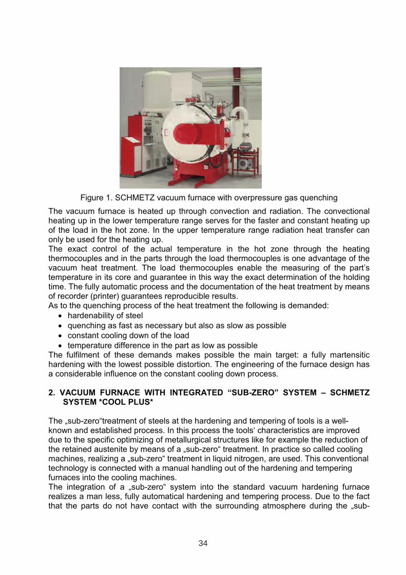
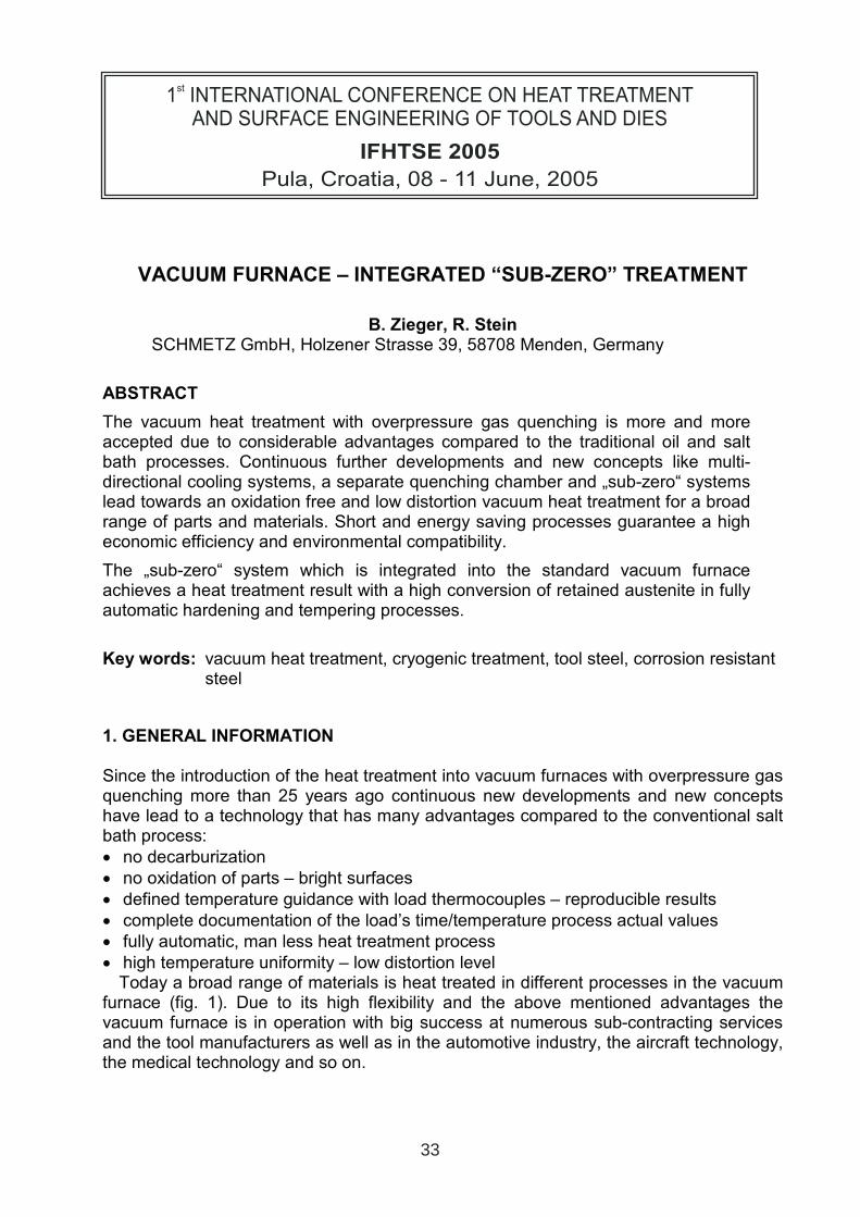
Figure 1. SCHMETZ vacuum furnace with overpressure gas quenching
The vacuum furnace is heated up through convection and radiation. The convectional heating up in the lower temperature range serves for the faster and constant heating up of the load in the hot zone. In the upper temperature range radiation heat transfer can only be used for the heating up. The exact control of the actual temperature in the hot zone through the heating thermocouples and in the parts through the load thermocouples is one advantage of the vacuum heat treatment. The load thermocouples enable the measuring of the part’s temperature in its core and guarantee in this way the exact determination of the holding time. The fully automatic process and the documentation of the heat treatment by means of recorder (printer) guarantees reproducible results. As to the quenching process of the heat treatment the following is demanded:
• hardenability of steel
• quenching as fast as necessary but also as slow as possible
• constant cooling down of the load
• temperature difference in the part as low as possible The fulfilment of these demands makes possible the main target: a fully martensitic hardening with the lowest possible distortion. The engineering of the furnace design has a considerable influence on the constant cooling down process.
2. VACUUM FURNACE WITH INTEGRATED “SUB-ZERO” SYSTEM – SCHMETZ SYSTEM *COOL PLUS*
The „sub-zero“treatment of steels at the hardening and tempering of tools is a well-known and established process. In this process the tools‘ characteristics are improved due to the specific optimizing of metallurgical structures like for example the reduction of the retained austenite by means of a „sub-zero“ treatment. In practice so called cooling machines, realizing a „sub-zero“ treatment in liquid nitrogen, are used. This conventional technology is connected with a manual handling out of the hardening and tempering furnaces into the cooling machines. The integration of a „sub-zero“ system into the standard vacuum hardening furnace realizes a man less, fully automatical hardening and tempering process. Due to the fact that the parts do not have contact with the surrounding atmosphere during the „sub-
34
zero“ treatment and the following tempering process no surface corrosion can occur. In this process the absolute metallic bright surface typical for the vacuum heat treatment is guaranteed. A smoothly controlled „sub-zero“ treatment is also guaranteed by means of the eligible „sub-zero“ gradient by using load thermocouples. Thus the risk of cracks due to a „rough“ „sub-zero“ treatment like in the usual processes is restricted considerably. The principle of the SCHMETZ system *COOL PLUS* is the inlet and the gasification of liquid nitrogen through a nozzle system into the graphite insulated hot zone of the vacuum furnace (fig 2). During the gasification the volume of nitrogen is increased by
700 times. In the load space the cold gaseous nitrogen is distributed constantly due to a “circulator” (convection fan). During this process the load loses the heat energy. Bymeans of a gas outlet pipe the heat energy is drained off together with the „used“ nitrogen.
Fig 2 scheme: “sub-zero” system for vacuum furnace
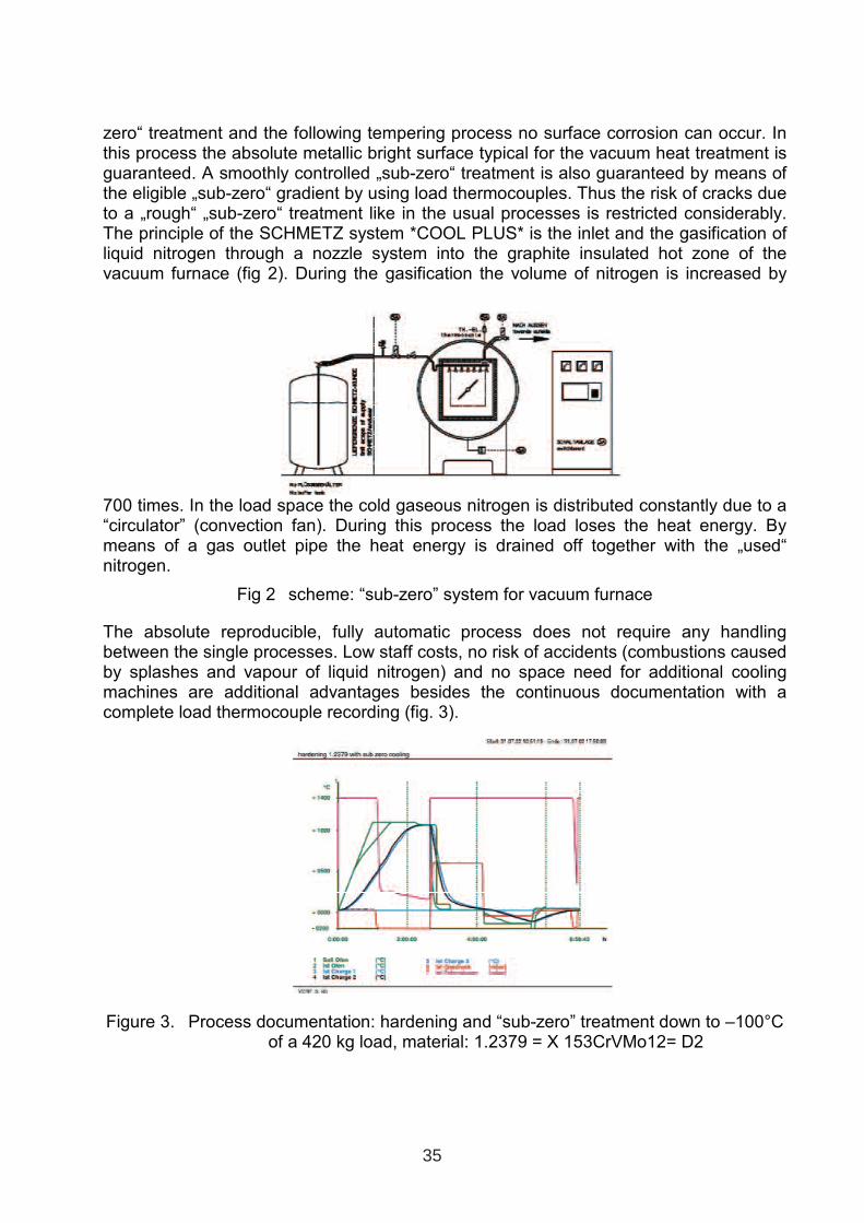
The absolute reproducible, fully automatic process does not require any handling between the single processes. Low staff costs, no risk of accidents (combustions caused by splashes and vapour of liquid nitrogen) and no space need for additional cooling machines are additional advantages besides the continuous documentation with a complete load thermocouple recording (fig. 3).
Figure 3. Process documentation: hardening and “sub-zero” treatment down to –100°C of a 420 kg load, material: 1.2379 = X 153CrVMo12= D2
35

Extensive examinations on stainless steels and tool steels, which were “sub-zero” treated in a vacuum furnace were carried out.
3. „SUB-ZERO“ TREATMENT OF STAINLESS STEELS
In the hardening and tempering process of stainless steels the possibility of the increase of the final hardness by means of the „sub-zero“ treatment between the hardening and tempering process was examined. With an increase of the final hardness the chip forming can be optimised and thus the production costs of the mechanical further treatment, which follows the heat treatment, can be reduced. In magazine loaded „combs“ of the material 1.4021 = X 20Cr 13 = 420 a load grossweight of 100 kg was hardened in a vacuum furnace at 1035 °C (Fig 4). The „sub-zero“ treatment down to –100 °C is followed by a tempering process at 150 °C (fig. 5). In this process the hardening and tempering process corresponds to the standard process.
Figure 4. Load: hardening and tempering process with “sub-zero” treatment of stainless steels
Figure 5. Process cycle: hardening and tempering process with “sub-zero” treatment of stainless steels
The final hardness of 640 HV after a standard hardening and tempering process could be increased by an additional „sub-zero“ treatment to 690 HV. Similar results were produced with “razor heads” of 1.4122 = X35CrMo17.
36

4. „SUB-ZERO“ TREATMENT OF TOOL STEELS
The aim of the „sub-zero“ treatment is the optimization of the dimensional stability due to the reduction of the retained austenite content at the hardening and tempering process of tool steels like 1.2379 = X 153 CrVMo 12= D2. Test parts (diameter 180 mm, height 80 mm) with a load gross weight of 2 kg were secondary hardened at 1060°C in a vacuum furnace with the dimension of the useful space 600 x 900 x 600 mm (w x l x h) and „sub-zero“ treated at different temperatures (0°C, -50 °C, -100 °C) (fig. 6). A part of the „sub-zero“ treated test parts with different temperatures were afterwards tempered at 510 °C. With a „sub-zero“ treatment of –100°C the retained austenite content can even be reduced to clearly below 10 % without tempering (fig. 7).
Figure 6. Load: hardening and “sub-zero” treatment of 1.2379 = X 153CrVMo12= D2
Figure 7. Retained austenite at the hardening and tempering process with “sub-zero” treatment of 1.2379 = X 153CrVMo12= D2
By means of the modular integration of the „sub-zero“ system into the standard vacuum furnace the process time and costs of the hardening and tempering process of steels
37

can be minimized considerably, through reduction of the tempering process and a higher dimensional stability of the parts if necessary.
5. CONCLUSION
Continuous further developments in the vacuum technology open in an ever broader sector of materials and parts the advantages of a modern, environmental friendly, fully automatic heat treatment cycle with a continuous documentation of the actual temperature sequence of the part.
38
THE MAIN PRINCIPLES OF INTENSIVE QUENCHING OF TOOLS
AND DIES
N.I. Kobasko
Intensive Technologies Ltd, Kyiv, UkraineIQ Technologies Inc., Akron, USA
ABSTRACT
The paper discusses in details the main principles of intensive quenching process as applied to steel tools, dies and other steel parts. The paper considers one- and two-step intensive quenching process for tools and dies. When applying a one- step intensive quenching method,the cooling is interrupted at the moment of time when the part surface compressive stresses are at their maximum value and the core has not reached the marten site start temperature. When applying a two-step intensive quenching technique, the duration of the first step of cooling depends on the duration of the “self- regulated thermal process”. At the second step ofsteel parts within the marten site range are cooled very rapidly. The paper presents also a new method of calculation and optimisation of the process of quenching.
Key words: Intensive quenching, one-and two-step quenching, low hardenability steel, optimisation, service life, cheap materials
1. INTRODUCTION
At present time the three main principles are used when developing intensive quenching of steel parts. The first principle means that the reason of additional strengthening(superstrengthening) of a material is high cooling rate within the martensite range. Detailed information is published in [1] The second principle allows choosing conditions of cooling forcreation of the maximal compressive stresses at the surface of the quenched steel parts. It means that very intensive cooling should be stopped at the moment of achievement of the maximum compressive stresses at the surface [2] The third principle means, that the chemical composition of steel should be such that after intensive cooling optimum depth of the quenched layer could be formed [3]. Below are three examples, which were realized in the practice.
1 INTERNATIONAL CONFERENCE ON HEAT TREATMENT
AND SURFACE ENGINEERING OF TOOLS AND DIES
st
Pula, Croatia 08 - 11 June, 2005,
IFHTSE 2005
39
2. DESIGN OF INDUSTRIAL QUENCH PROCESSES
It is required to determine the speed of movement of the conveyor, which would provide temperature 650 ºF (343 ºC) at the core of the part when it should be delivered from the quenchant. To make these calculations we are using equation presented in [4, 5], i.e.
KTT
TTb
KnLaLw
m
m
−
−+Ω
==
0lnτ
; (1)
where: a is average thermal diffusivity of the material for the range of temperatures m
TT −0 ;
Kn is Kondratjev number (dimensionless value), Ω =0.48 for cylinder-shaped bodies, b=1 if the core’s temperature is determined, T0 is austenitizing temperature or temperature at the time of immersing the part into the quenchant, Tm is temperature of the medium, if convectionprevails, or temperature of boiling if nucleate boiling prevails.
Table I Kondratjev number Kn for 10% aqueous solutions of UCON A and UCON E at temperature of 90 ºF (~32 ºC) and speed of the stream of 80 fpm (~0.4 m/s).Temperature of the core of probes is 1300 ºF (704 ºС) [5]
Probe diameter in inches (mm)
UCON A UCON E Kn
0.5(12.7)
0.4240.417
0.4120.408 0.415
1(25.4)
0.5460.526
0.4880.488 0.512
1.5(38.1)
0.5780.556
0.5230.514 0.543
The average thermal diffusivity a of the overcooled austenite within the temperature range of 1550 ºF – 200 ºF (840ºC – 100 ºC) is equal to 5.36·10-6 m2/s. Having all above-stated facts we calculate what speed of the conveyor should be to provide the core’s temperature 650 ºF (343 ºC) for a cylindrical part made of AISI 4140 steel and having diameter of 25 mm and height of 50 mm. At the time of immersion the part has the same temperature of 1550 ºF through all cross-sections. To answer this question, it is necessary just to determine Kondratjev number Kn. For the determination of Kn there must be available an experimental database.
40
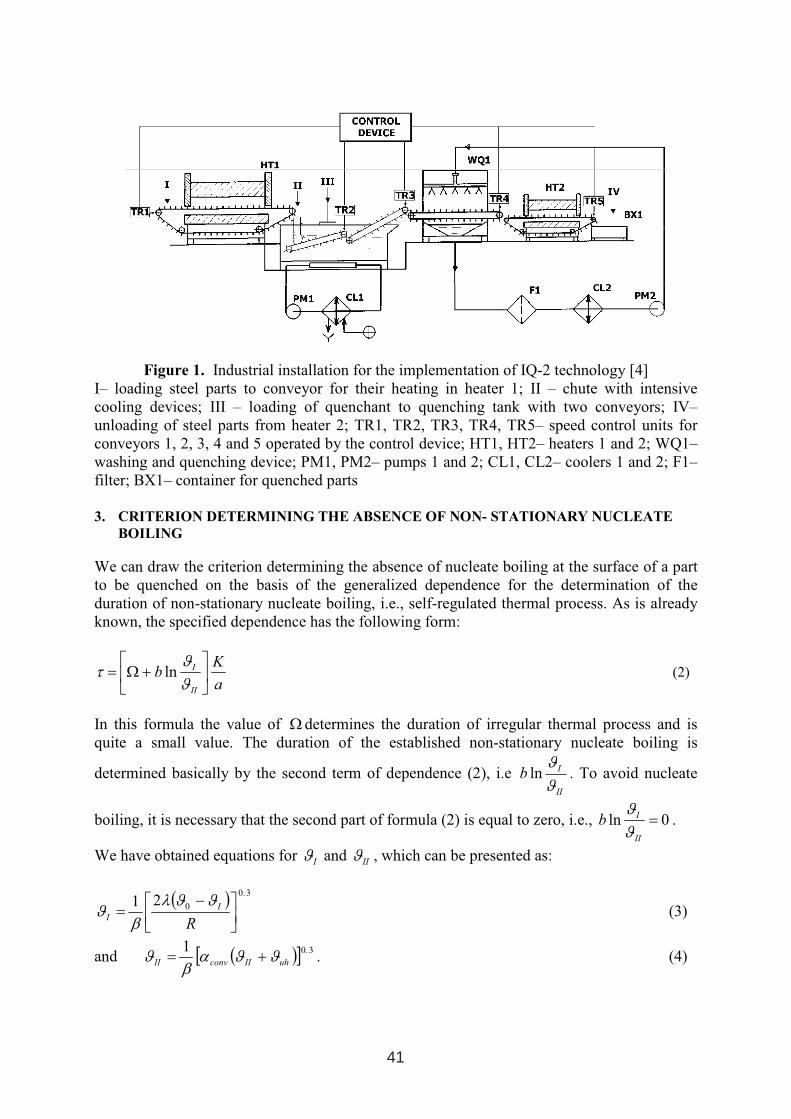
Figure 1. Industrial installation for the implementation of IQ-2 technology [4] І– loading steel parts to conveyor for their heating in heater 1; II – chute with intensive cooling devices; ІІІ – loading of quenchant to quenching tank with two conveyors; ІV– unloading of steel parts from heater 2; TR1, ТR2, ТR3, ТR4, ТR5– speed control units for conveyors 1, 2, 3, 4 and 5 operated by the control device; HT1, HT2– heaters 1 and 2; WQ1–washing and quenching device; PM1, PM2– pumps 1 and 2; CL1, CL2– coolers 1 and 2; F1– filter; BX1– container for quenched parts
3. CRITERION DETERMINING THE ABSENCE OF NON- STATIONARY NUCLEATE
BOILING
We can draw the criterion determining the absence of nucleate boiling at the surface of a part to be quenched on the basis of the generalized dependence for the determination of the duration of non-stationary nucleate boiling, i.e., self-regulated thermal process. As is already known, the specified dependence has the following form:
a
Kb
II
I
+Ω=
ϑ
ϑτ ln (2)
In this formula the value of Ω determines the duration of irregular thermal process and is quite a small value. The duration of the established non-stationary nucleate boiling is
determined basically by the second term of dependence (2), i.e II
Ib
ϑ
ϑln . To avoid nucleate
boiling, it is necessary that the second part of formula (2) is equal to zero, i.e., 0ln =
II
Ib
ϑ
ϑ.
We have obtained equations forI
ϑ and II
ϑ , which can be presented as:
( )3.0
021
−=
R
I
I
ϑϑλ
βϑ (3)
and ( )[ ]3.01
uhIIconvIIϑϑα
βϑ += . (4)
41
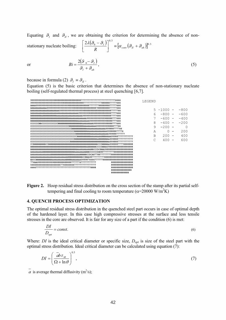
Equating I
ϑ and II
ϑ , we are obtaining the criterion for determining the absence of non-
stationary nucleate boiling: ( )
( )[ ]3.0
3.0
02uhIIconv
I
Rϑϑα
ϑϑλ+≡
−
or( )
uhI
IBi
ϑϑ
ϑϑ
+
−=
02, (5)
because in formula (2)III
ϑϑ ≡ .
Equation (5) is the basic criterion that determines the absence of non-stationary nucleate boiling (self-regulated thermal process) at steel quenching [6,7].
999999999999999999888888888888888888877777777777777777777777776666
999999999999999999999999888888888888888777777777777788888877777666
AAAA99999999999999999999999988888888888888877777778888888877777666
AAAAAAAAAAAA999999999999999999998888888888888888788888888877777666
AAAAAAAAAAAAAAAAAAAAA999999999999999999888888888888888888887777766
AAAAAAAAAAAAAAAAAAAAAAAAAAAAAAAAAAA9999999988888888888888887777666
BBBBBBBBABBBBBBBBBBAAAAAAAAAAAAAAAAAAA9999999999999999888887777666
BBBBBBBBBBBBBBBBBBBBBBBBBBBBAAAAAAAAAAAAA9999999999999988888777666
BBBBBBBBBBBBBBBBBBBBBBBBBBBBBBBBBBAAAAAAAAA99999999999998888777666
CCCCCCBBCCCCCCCCCCCCBBBBBBBBBBBBBBBBBAAAAAAAAA99999999998888777666
CCCCCCCCCCCCCCCCCCCCCCCCCCCCBBBBBBBBBBBAAAAAAAAA999999999888877766
CCCCCCCCCCCCCCCCCCCCCCCCCCCCCCBBBBBBBBBBBAAAAAAAAAAAAAA999888777766
CCCCCCCCCCCCCCCCCCCCCCCCCCCCCCCCBBBBBBBBBBAAAAAAAAAAAAAA999888877776
CCCCCCCCCCCCCCCCCCCCCCCCCCCCCCCCCBBBBBBBBBBBAAAAAAAAAAAAA999888777777
CCCCCCCCCCCCCCCCCCCCCCCCCCCCCCCCCCBBBBBBBBBBAAAAAAAABBBAAAA9998877777777777
CCCCCCCCCCCCCCCCCCCCCCCCCCCCCCCCBBBBBBBBBBBBBBBBAABBBBBBAA99988877777777777
CCCCCCCCCCCCCCCCCCCCCCCCCCCCCBBBBBBBBBBBBBBBBBBBBBBBBBBBAA99988877777777777
CCBBBBBBBBBCCBBBBBBBBBBBBBBBBBBBBBBBBBBBBBBBBBBBBCCCBBBBAA99888877778888888
BBBBBBBBBBBBBBBBBBBBBBBBBBBBBBBBBBBBBBBBBABBBBBBCCCCBBBA9988888888888888888
BBBBBBBBBBBBBBBBBBBBBBBBBBBBBBBBBBAAAAAAAAAABBCCCDCBBA998888888888888888888
AAAAAAAAABBBBBBBBBBBBBBBBBBBBBBBAAAAAAAABBBCCCCCCDB987777777788888888888888
AAAAAAAAAAAAAAABBBBBBBBBBBBBBBBAAAAABBBBBCCDCA87788777777778888888888888888
AAAAAAAAAAAAAAAAAAAAAAAAAAABBBBBBBBBBBCCBBA98777777777888888888888888888888
EDCCBBBBBBBBBBBAAAAAAAAAAABBBBAAAAAAA99998766667777778888888888888888888888
776AA9999999999998888888888888777777677777777777 8888888888888888
566666666666666666666677666666667777777777777777 8888888888888888
666677777777777777777777777777777777777777778888 8888888888888888
888888888888888
8888888888888
LEGEND
5 –1000 - -800
6 -800 - -600
7 -600 - -400
8 -400 - -200
9 -200 - 0
A 0 - 200
B 200 - 400
C 400 - 600
Figure 2. Hoop residual stress distribution on the cross section of the stamp after its partial self-tempering and final cooling to room temperature (α=20000 W/m2K)
4. QUENCH PROCESS OPTIMIZATION
The optimal residual stress distribution in the quenched steel part occurs in case of optimal depthof the hardened layer. In this case high compressive stresses at the surface and less tensile stresses in the core are observed. It is fair for any size of a part if the condition (6) is met:
.constD
DI
opt
= (6)
Where: DI is the ideal critical diameter or specific size, Dopt is size of the steel part with the optimal stress distribution. Ideal critical diameter can be calculated using equation (7):
5.0
ln
+Ω=
θ
τM
baDI , (7)
a is average thermal diffusivity (m2/s);
42
mτ is limit time of the core cooling from the austenitizing temperature to martensite start temperature,
providing the formation of 99% or 50% martensite, 48.0=Ω for a bar (or cylinder),
mM
m
TT
TT
−
−=
0θ , T0 is austenitizing temperature, b is parameter depending only on form of steel
part; Tm is temperature of quenchant; TM is martensite start temperature at limit time of cooling.
Table II. Commercial and industrially tested technologies using intensive quenching [8]
Steel parts Steel for IQprocess
Steels and technologies which werereplaced by IQ
Cylindrical and conical gears of trucksand tractors
58(55PP) 30KhGT (and other carburizing steels, carburizing for 10 hr.
Cylindrical gears of electric driven train transmissions and locomotives (m=10 mm)
ShKh4 20KhN3A, 20Kh2N4А, carburizingfor 30 hr.
Small modulated gears (m=4-6 mm) with splined openings (solar, satellite ones)
58(55PP) 18KhGT and others, carburizing for 15 hr.
Rear wheel truck half-axles 47GT 40KhGRT and others, through hardening in oil
Dies for punching the bearing bolls ShKh4 Enhanced alloyed steels, through hardening in oil
Table III. Steels of low hardenability for Intensive Quenching (IQ) [8] Steel,GOST C Mn Si Ni Cr Mo Ti Al Cu
58(55PP)GOST 1050
0.55- -0.63
0.2 0.1- -0.3
0.25 0.15 - - - 0.2
47GT 0.44- -0.51
0.95- -1.25
0.10- -0.25
0.25 0.25 - 0.06- -0.12
- 0.30
ShKh2 1.15- -1.25
0.15- -0.30
0.15- -0.30
0.10 0.15 <0.03 0.06- 0.12
0.015-0.03
0.12
ShKh4 GOST 801
0.95- -1.05
0.15- -0.30
0.15- -0.30
0.30 0.25 - - - 0.25
45S 0.42-0.48
0.17-0.32 0.40-0.65 0.20 0.25 - - - 0.15
70PP 0.66- -0.73
0.15- -0.30
0.15- -0.30
0.25 0.25 - - - 0.25
115PP 1.10- -1.20
0.40- -0.60
0.15- -0.30
0.20 0.25 - 0.06- -0.12
- 0.20
43
CONCLUSIONS
1. Delayed transformation austenite into martensite at the first step of cooling and very rapid cooling within the martensite range at the second step results in decreasing of distortion of steel parts and increasing mechanical properties of a material.
2. Intensive cooling from austenite temperature till the time of the formation of the optimal quenched layer and the maximal compressive stresses at the surface with the subsequent tempering of the quenched layer also reduces distortion and increases mechanical properties of the materials.
3. Low-hardenability steels, which provide optimal depth of the quenched layer in conditions of intensive cooling, reduce distortion and increase service life of steel parts similarly to items 1and 2.
4. The software and original technique of calculations of optimal conditions of quenching depending on the shape and the sizes of parts, conditions of cooling and chemical composition of steel has been developed.
5. More detailed calculations are carried out on the basis of the software TANDEM developed inUkraine.
6. At calculations of the optimal depth of quenched layer it is possible to use chemical compositions of steels published in “Worldwide Guide to Equivalent Irons and Steels, 4th Edition, (William C. Mack, Coordinating Editor), ASM International, 2002 [9].
References
1. N.I.Kobasko, Steel Superstrengthening Phenomenon, Journal of ASTM, February 2005,
Vol. 2, No 2, Paper ID JAI 12824, Available on line at www.astm.org2. N.I.Kobasko, Intensive Steel Quenching Methods, In a Handbook: Theory and Technology of
Quenching, B. Liscic, H.M. Tensi, and W. Luty, Ed., Springer – Verlag, Berlin, 1992, p 367. – 389.
3. N.I.Kobasko, Quench Process Optimization, Proc.of the 6th
International Conf. on Heat
Treating of Materials (OTTOM-6), 16-20 May,2005, Kharkov, Ukraine4. Ukrainian Patent No 27059 5. N.I.Kobasko, G.E.Totten, Design of Industrial Quenching Processes, Proc. of the 14
th
IFHTSE Congress, Beijing, China, 2004. 6. Ukrainian Patent No 56189 7. US Patent #6,364,974B18. B.K.Ushakov, K.Z.Shepeliakovskii, V.M.Fedin, A.A.Kuznetsov, N.Yu.Kuznetsova,
Development of Through Surface Hardening Method for Heavy-Load Products and Machine Parts, Steel No. 11, 2001, рр. 64.-68.
9. Worldwide Guide to Equivalent Irons and Steels, 4th Edition, (William C. Mack, Coordinating Editor), ASM International, 2002.
44
OPTIMIZING THE VACUUM-HEAT-TREATMENT OF HOT-WORK
TOOL STEELS BY LINEAR ELASTIC FRACTURE MECHANICS
Vojteh Leskovšek1, Borivoj Šuštaršič1, Gorazd Jutriša1, Dani Baksa2, Janez Kopač3
1Institute of Metals and Technology, Lepi pot 11, 1000 Ljubljana, Slovenia2Unior Kovaška industrija d.d., Zreče, Slovenia3Faculty of Mechanical Engineering, Aškerčeva 6, 1000 Ljubljana, Slovenia
ABSTRACT
Linear elastic fracture mechanics was used to optimise the vacuum-heat-treatment procedures
for conventional hot-work AISI H11 tool steel. The fracture toughness was determined with
non-standard, circumferentially notched and fatigue-precracked tensile-test specimens. The
fracture-testing method is sensitive to changes caused by variations in the microstructure
resulting from the austenitizing and tempering temperatures as well as the homogeneity of the
material itself. The combined tempering diagram– Rockwell-C hardness, Fracture toughness
KIc, Tempering temperature– was used for the choice of the vacuum-heat-treatment
parameters necessary to obtain the best properties for a given application with respect to the
investigated steel.
Key words: conventional hot work tool steel, vacuum heat-treatment, fracture toughness,
hardness, microstructure
1. INTRODUCTION
The process parameters, the work material and the tool material determine the dominant
damage mechanism. For this reason, improving the tool’s performance requires a detailed
knowledge of the relevant damage mechanisms. It is also clear that the tool material itself
plays a very important role, and that the properties’ profile of the tool material greatly
influences its lifetime. Despite the enormous variety of tooling operations there are some
basic properties of tool materials that are common to almost all applications. These properties
are the toughness, which prevents instantaneous fracture of the tool or tool edges due to local
overload, and the hardness, which must be sufficiently high to avoid local plastic deformation.
1 INTERNATIONAL CONFERENCE ON HEAT TREATMENT
AND SURFACE ENGINEERING OF TOOLS AND DIES
st
Pula, Croatia 08 - 11 June, 2005,
IFHTSE 2005
45
Hardness and toughness are more or less mutually exclusive properties, which means the
prevention of instantaneous tool failures is often connected with a critical hardness level that
must not be exceeded for a specific application. The hardness and the toughness of hot-work
tool steel depend a lot on the vacuum-heat-treatment procedure. Hardness is closely related to
ductility and toughness, in particular the latter. In this paper the influence of the austenitizing
and tempering temperatures on the hardness and fracture toughness of conventional hot-work
AISI H11 tool steel is investigated and discussed.
2. THEORY
According to ref. [1] toughness and ductility are the most relevant properties in terms of
resistance to total failure as a result of overloading. Toughness and ductility are two different
material properties, even though both– unfortunately– are sometime denominated as
toughness. The opposite of both properties is, however, the same, i.e., brittleness. No
standardised tests for the determination of toughness or ductility are in common use; often,
data determined with different test methods are available, which makes them difficult to
compare, and this can lead to confusion. Toughness and ductility are different characteristics,
and for this reason it is necessary to distinguish between them [1]. Their importance for tool-
steel performance depends a lot on the geometry of the tool [1]. In the case of un-notched
specimens or specimens with smooth notches, the ductility and fracture stress are the relevant
material properties; however, if sharp notches or cracks are present, fracture toughness is the
most relevant property. The conclusion, therefore, is that the tool steel should be optimised in
terms of ductility and fracture stress for un-notched regions and in terms of fracture toughness
for notched regions. The toughness depends a lot on the hardness, and the hardening
mechanism is different in as-quenched and fully-heat-treated tool steels. In the as-quenched
tool work-hardening and solid-solution hardening, mostly due to carbon in the solid solution,
mainly affect the steel’s hardness. Tempering leads to the precipitation of carbide particles
and significantly decreases the carbon content in the solid solution and the dislocation density.
The hardness of fully-heat-treated tool steels is therefore mainly affected by precipitates that
cause precipitation hardening and, to small extent, solid-solution hardening. The work-
hardening and grain refinement seem to play only a minor role [2].
The most reliable measure of toughness is the plain-strain fracture toughness. The minimum
size of the specimens depends on the yield stress and the fracture toughness of the tested
material, both of which are necessary for a plane-strain deformation. A fatigue crack of a
46
defined length is propagated from a mechanical notch in the specimens ensuring that the
notch effect is a maximum and equal for all tests. The same value of fracture toughness
should be found for tests on specimens of the same material with different geometries and
with a critical combination of crack size and shape and fracture stress. Within certain limits,
this is indeed the case, and information about the fracture toughness obtained under standard
conditions can be used to predict failure for different combinations of stress and crack size
and for different geometries [3].
3. EXPERIMENTAL
3.1 Material and vacuum heat treatment
Conventional hot-work AISI H11 tool steel delivered in the shape of plates with dimensions
263 mm x 220 mm x 25 mm, cut from forged-and-soft-annealed master blocks with
dimensions 263 mm x 220 mm x 4000 mm and the following chemical composition (mass
content in %): 0.39 % C; 1.06 % Si; 0.32 % Mn; 0.019 % P; 0.004 % S; 4.91 % Cr; 0.11 %
Ni; 1.17 % Mo; 0.37 % V; and 0.011 % Ti was used. The KIc-test specimens,
circumferentially notched and fatigue-precracked tensile-test specimens, were cut from these
plates in the short transverse direction. A round notch with a fatigue crack at the notch root
was at the same distance (60 mm) from the surface of the master block in all the KIc-test
specimens. The specimens were heat treated in a horizontal vacuum furnace with uniform
high-pressure gas-quenching using nitrogen (N2) at a pressure of 1.05 bar. After the last
preheat (850 °C) the specimens were heated (10 °C/min) to the austenitizing temperatures
1000 °C, 1020 °C and 1050 °C, soaked for 20 minutes, gas quenched to a temperature of 100
°C. First temper was performed at 540 °C and second at different temperatures between 540
°C and 620 °C as shown in Fig. 2, each time for 2 hours, respectively. For each group of
vacuum-heat-treatment conditions from A to C, five KIc-test specimens were tested for each
second tempering temperature.
3.2 Hardness and fracture-toughness tests
The Rockwell-C hardness (HRc) was measured on the individual groups of the KIc-test
specimens using a Wilson 4JR hardness machine. Circumferentially notched and fatigue-
precracked tensile-test specimens with the dimensions indicated in Fig. 1 were used for this
investigation [4].
47
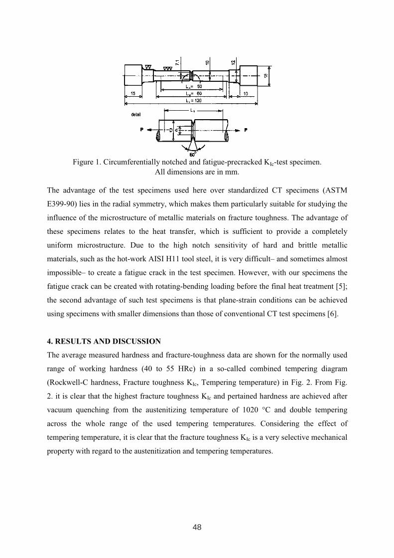
Figure 1. Circumferentially notched and fatigue-precracked KIc-test specimen. All dimensions are in mm.
The advantage of the test specimens used here over standardized CT specimens (ASTM
E399-90) lies in the radial symmetry, which makes them particularly suitable for studying the
influence of the microstructure of metallic materials on fracture toughness. The advantage of
these specimens relates to the heat transfer, which is sufficient to provide a completely
uniform microstructure. Due to the high notch sensitivity of hard and brittle metallic
materials, such as the hot-work AISI H11 tool steel, it is very difficult– and sometimes almost
impossible– to create a fatigue crack in the test specimen. However, with our specimens the
fatigue crack can be created with rotating-bending loading before the final heat treatment [5];
the second advantage of such test specimens is that plane-strain conditions can be achieved
using specimens with smaller dimensions than those of conventional CT test specimens [6].
4. RESULTS AND DISCUSSION
The average measured hardness and fracture-toughness data are shown for the normally used
range of working hardness (40 to 55 HRc) in a so-called combined tempering diagram
(Rockwell-C hardness, Fracture toughness KIc, Tempering temperature) in Fig. 2. From Fig.
2. it is clear that the highest fracture toughness KIc and pertained hardness are achieved after
vacuum quenching from the austenitizing temperature of 1020 °C and double tempering
across the whole range of the used tempering temperatures. Considering the effect of
tempering temperature, it is clear that the fracture toughness KIc is a very selective mechanical
property with regard to the austenitization and tempering temperatures.
48
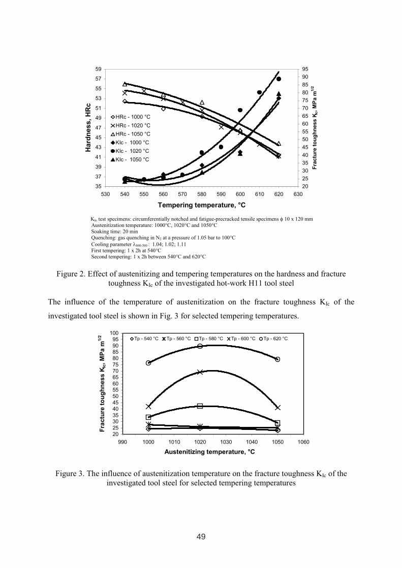
35
37
39
41
43
45
47
49
51
53
55
57
59
530 540 550 560 570 580 590 600 610 620 630
Tempering temperature, °C
Hard
ness,
HR
c
20
25
30
35
40
45
50
55
60
65
70
75
80
85
90
95
Fra
ctu
reto
ug
hn
ess
KIc
,M
Pa
m1/2
HRc - 1000 °C
HRc - 1020 °C
HRc - 1050 °C
KIc - 1000 °C
KIc - 1020 °C
KIc - 1050 °C
KIc test specimens: circumferentially notched and fatigue-precracked tensile specimens φ 10 x 120 mm Austenitization temperature: 1000°C, 1020°C and 1050°C Soaking time: 20 min Quenching: gas quenching in N2 at a pressure of 1.05 bar to 100°C Cooling parameter λ800-500 : 1.04; 1.02; 1.11 First tempering: 1 x 2h at 540°CSecond tempering: 1 x 2h between 540°C and 620°C
Figure 2. Effect of austenitizing and tempering temperatures on the hardness and fracturetoughness KIc of the investigated hot-work H11 tool steel
The influence of the temperature of austenitization on the fracture toughness KIc of the
investigated tool steel is shown in Fig. 3 for selected tempering temperatures.
2025
3035
404550
5560
657075
80859095
100
990 1000 1010 1020 1030 1040 1050 1060
Austenitizing temperature, °C
Fra
ctu
reto
ug
hn
es
sK
Ic,M
Pa
m1
/2 Tp - 540 °C Tp - 560 °C Tp - 580 °C Tp - 600 °C Tp - 620 °C
Figure 3. The influence of austenitization temperature on the fracture toughness KIc of the investigated tool steel for selected tempering temperatures
49
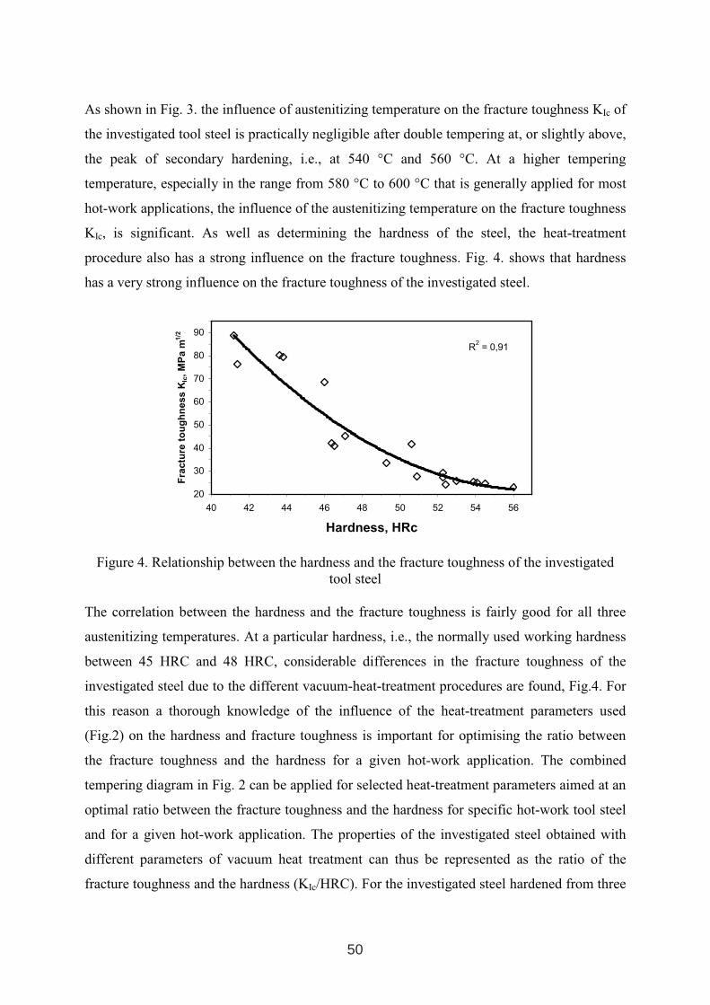
As shown in Fig. 3. the influence of austenitizing temperature on the fracture toughness KIc of
the investigated tool steel is practically negligible after double tempering at, or slightly above,
the peak of secondary hardening, i.e., at 540 °C and 560 °C. At a higher tempering
temperature, especially in the range from 580 °C to 600 °C that is generally applied for most
hot-work applications, the influence of the austenitizing temperature on the fracture toughness
KIc, is significant. As well as determining the hardness of the steel, the heat-treatment
procedure also has a strong influence on the fracture toughness. Fig. 4. shows that hardness
has a very strong influence on the fracture toughness of the investigated steel.
R2
= 0,91
20
30
40
50
60
70
80
90
40 42 44 46 48 50 52 54 56
Hardness, HRc
Fra
ctu
reto
ug
hn
es
sK
Ic,
MP
am
1/2
Figure 4. Relationship between the hardness and the fracture toughness of the investigated tool steel
The correlation between the hardness and the fracture toughness is fairly good for all three
austenitizing temperatures. At a particular hardness, i.e., the normally used working hardness
between 45 HRC and 48 HRC, considerable differences in the fracture toughness of the
investigated steel due to the different vacuum-heat-treatment procedures are found, Fig.4. For
this reason a thorough knowledge of the influence of the heat-treatment parameters used
(Fig.2) on the hardness and fracture toughness is important for optimising the ratio between
the fracture toughness and the hardness for a given hot-work application. The combined
tempering diagram in Fig. 2 can be applied for selected heat-treatment parameters aimed at an
optimal ratio between the fracture toughness and the hardness for specific hot-work tool steel
and for a given hot-work application. The properties of the investigated steel obtained with
different parameters of vacuum heat treatment can thus be represented as the ratio of the
fracture toughness and the hardness (KIc/HRC). For the investigated steel hardened from three
50
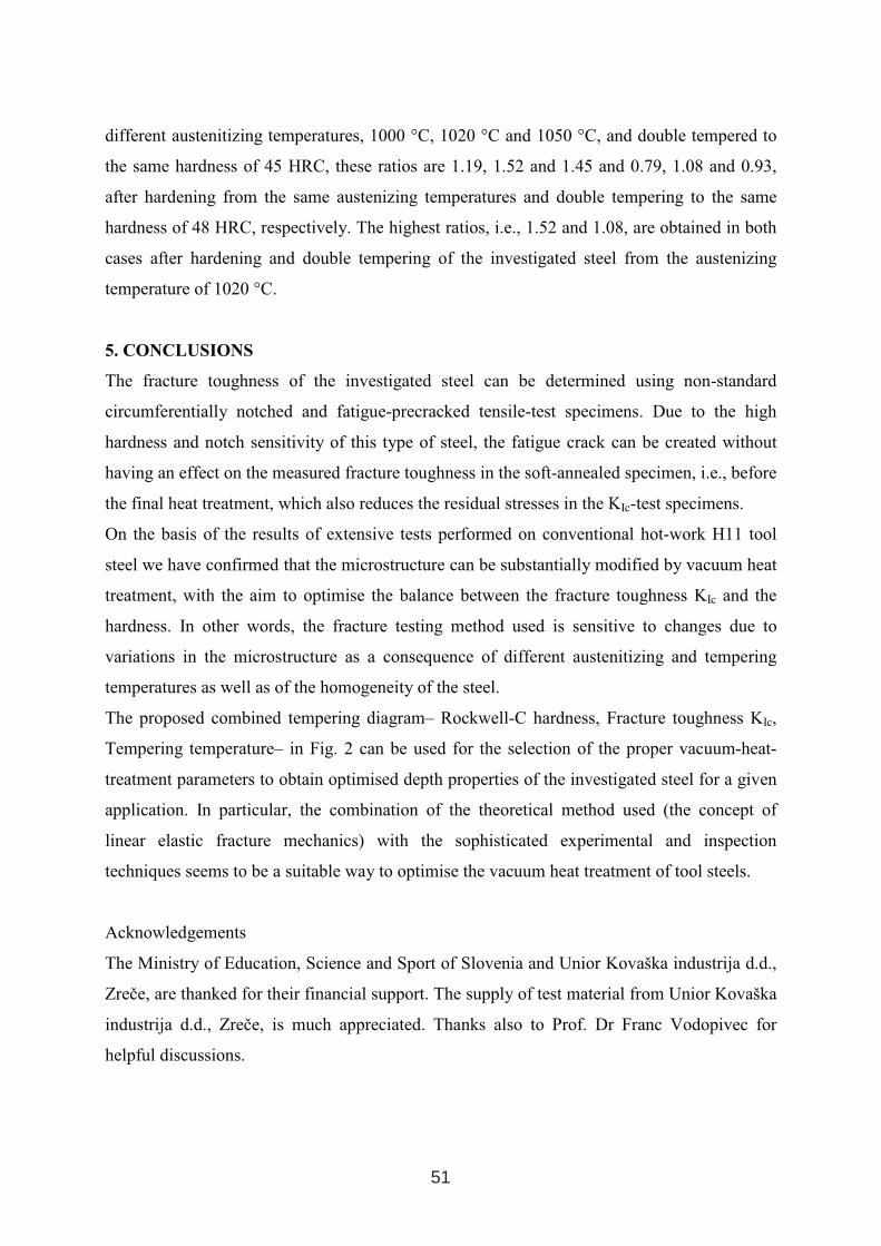
different austenitizing temperatures, 1000 °C, 1020 °C and 1050 °C, and double tempered to
the same hardness of 45 HRC, these ratios are 1.19, 1.52 and 1.45 and 0.79, 1.08 and 0.93,
after hardening from the same austenizing temperatures and double tempering to the same
hardness of 48 HRC, respectively. The highest ratios, i.e., 1.52 and 1.08, are obtained in both
cases after hardening and double tempering of the investigated steel from the austenizing
temperature of 1020 °C.
5. CONCLUSIONS
The fracture toughness of the investigated steel can be determined using non-standard
circumferentially notched and fatigue-precracked tensile-test specimens. Due to the high
hardness and notch sensitivity of this type of steel, the fatigue crack can be created without
having an effect on the measured fracture toughness in the soft-annealed specimen, i.e., before
the final heat treatment, which also reduces the residual stresses in the KIc-test specimens.
On the basis of the results of extensive tests performed on conventional hot-work H11 tool
steel we have confirmed that the microstructure can be substantially modified by vacuum heat
treatment, with the aim to optimise the balance between the fracture toughness KIc and the
hardness. In other words, the fracture testing method used is sensitive to changes due to
variations in the microstructure as a consequence of different austenitizing and tempering
temperatures as well as of the homogeneity of the steel.
The proposed combined tempering diagram– Rockwell-C hardness, Fracture toughness KIc,
Tempering temperature– in Fig. 2 can be used for the selection of the proper vacuum-heat-
treatment parameters to obtain optimised depth properties of the investigated steel for a given
application. In particular, the combination of the theoretical method used (the concept of
linear elastic fracture mechanics) with the sophisticated experimental and inspection
techniques seems to be a suitable way to optimise the vacuum heat treatment of tool steels.
Acknowledgements
The Ministry of Education, Science and Sport of Slovenia and Unior Kovaška industrija d.d.,
Zreče, are thanked for their financial support. The supply of test material from Unior Kovaška
industrija d.d., Zreče, is much appreciated. Thanks also to Prof. Dr Franc Vodopivec for
helpful discussions.
51
1. R. Ebner, H. Leitner, F. Jeglitsch and D. Caliskanoglu : Methods of Property OrientedTool Steel Design, Proceeding of 5th International Conference on Tooling, Leoben,Sept.29th to October 1st 1999, University of Leoben, Austria, 3-24
2. Leitner, H.: "EinfluB der Austenitkorngr6Be auf die Zahigkeit des Schnellarbeitsstahles S 6-5-2-5", Diploma Thesis, University of Leoben (1996)
3. M. Janssen, J. Zuidema, R.J.H. Wanhill: Fracture Mechanics, 2-nd Edition, Delft University Press, Delft, Netherlands, 2002
4. B.Ule, V. Leskovsek, B.Tuma: Estimation of plain strain fracture toughness of AISI M2 steel from precracked round-bar specimens, Engng Fracture Mech 2000; 65, 559-572
5. Wang Chang: An improvement of applying similarity methods to fracture mechanics- measurement of fracture toughness KIc, KQ values by small-scalle single specimen,Engng Fracture Mech 1990;36, 313-20
6. H.F.Fischmeister, Toughness in high speed steels and hard metals, Mater. Dev. (1982), 127-140.
52
References
MICROSTRUCTURAL EVOLUTION OF A RAPIDLY SOLIDIFIED HIGH-SPEED STEEL DURING HIGH TEMPERATURE ANNEALING
C. Stotter1), H. Leitner2), R. Ebner1, 2, 3), P. Ramminger1), E. Brandstätter3)
1) Materials Center Leoben Forschung GmbH, Leoben, Austria 2) Department of Physical Metallurgy and Materials Testing, University of Leoben,
Leoben, Austria 3) Laser Center Leoben, JOANNEUM RESEARCH Forschungsgesellschaft m.b.H.,
Niklasdorf, Austria
ABSTRACT
The microstructural phase evolution of a laser cladded rapidly solidified HS10-2-5-8 high-speed steel was examined during subsequent high temperature annealing using XRD, HT-XRD and SEM with EDX-analyses. The specimens were produced with a 6 kW continuous wave CO2 laser. The layers possess a fine rapidly solidified microstructure, which is build-up of dendrite arms, with a substructure of martensite and retained austenite and a fine interdendritic eutectic comprising M2C and MC carbide phases. The M2C carbides decompose rapidly to MC and M6C in less then 3 minutes after attaining the annealing temperature of 1150°C followed by further precipitation of carbides preferentially in the segregated interdendritic zones. After annealing for 3 h no further chemical inhomogeneities could be observed and only coarsening of the carbides takes place.
Key words: rapid solidification, high-speed steel, phase transformation, microstructure, heat treatment
1 INTERNATIONAL CONFERENCE ON HEAT TREATMENT
AND SURFACE ENGINEERING OF TOOLS AND DIES
st
Pula, Croatia 08 - 11 June, 2005,
IFHTSE 2005
53
1. INTRODUCTION
The development of new materials by means of laser alloying was found to be attractive particularly because of its capability to overcome the limitations related to equilibrium thermodynamics [1]. New types of high-speed steels with attractive properties are possible. The high cooling rates between 103 to 106 K/s [2], which are characteristic for laser-beam surface melting of steels, ensure rapid quenching of the molten surfaces, resulting in very fine microstructures and the extension of solid solubility limits [3]. Due to the supersaturation and the high cooling rates the microstructure at room temperature exhibits a larger amount of retained austenite. However, the as-cast microstructure does not provide adequate mechanical properties so that subsequent annealing treatments have to be applied. Numerous papers are dealing with surface melting and subsequent rapid solidification of common high-speed steels [4-9], and also literature about compositional modifications by alloying can be found [10, 11]. However, there are still open questions concerning the microstructural evolution during subsequent heat treatment and related mechanical properties of rapidly solidified high-speed steels. In the present study microstructural changes during annealing of a laser cladded, rapidly solidified high-speed steel HS10-2-5-8 have been investigated. For the characterisation of the microstructural changes scanning electron microscopy (SEM) in combination with energy dispersive chemical analyses (EDX) and X-ray diffraction analyses (XRD) have been applied.
2. EXPERIMENTAL
The investigated high-speed steel (HSS) was produced by laser cladding on a common X32CrMoV3 3 (AISI ~ H10) steel in soft-annealed condition [12]. For the production of the laser clad a HS10-2-5-8 powder was used. The chemical compositions of the gas atomized HSS powder and the substrate used are summarised in Table I.
Tabele. I: Nominal chemical composition of the powder and the substrate material used in the present work (wt.%).
Steel C Cr W Mo V Co Fe
HS10-2-5-8 1.60 4.8 10.5 2.0 5.0 8.0 bal.
X32CrMoV 3 3 0.31 2.9 - 2.8 0.5 - bal.
The laser cladding process was performed with a 6 kW continuous CO2 laser from TRUMPF Laser GmbH. For the production of the HSS the following laser parameters were used: 2,5 kW laser power, 2 mm beam diameter and 1 m/min beam scanning speed. The powder was delivered to the area of interaction by a pneumatic powder delivery system Twin 10C from Plasmatechnik AG. The feed flow of the powder was continuously regulated at a fixed rate of 2,1 g/min by injecting a small amount of argon gas through the powder tube. Oxidation was minimized by using argon as shielding gas during cladding. The specimens were moved relatively to the laser beam. Seven consecutive layers were produced on each specimen. After cladding of each layer, the laser power was turned off at the end of each pass and the nozzle was rapidly returned to the new starting position, which was chosen in order to get an
54
overlap rate of approximately 30 % between the tracks. After cladding, the substrate material was separated from the HSS. The characterization of the microstructure in the rapidly solidified condition and after various heat treatments was carried out using a Cambridge Stereoscan 360 scanning electron microscope. Chemical analyses were performed by means of energydispersive X-ray microanalyses using a Link-system. The heat treatments of the various samples were performed with a quenching dilatometer Bähr Dil 805 D. The samples (diameter: ø5 mm, length: 9 mm) were heated to 1150 °C by inductive heating at a heating rate of 115 K/s and kept for 3, 30, 60, 120, 180 min. Then, the samples were quenched to room temperature with a λ-value of 0.2. The λ-value is defined as the cooling time in seconds between 800 °C and 500 °C divided by 100. After heat treatment the microstructure of the samples was analyzed regarding microstructural changes by using SEM and X-ray diffraction. The laboratory X-raydiffraction system (Bruker-AXS D8 Advance) is using a Cu – radiation (1.5406 Ǻ), parallel beam optics and a energy dispersive detection system (Sol-X, BalticInstruments) to avoid fluorescence effects. For the qualitative phase evaluation the software package EVA (v. 9.0; Bruker-AXS) as well as the mandatory ICDD-PDF-2 Release 2002 has been used. Further structural informations where obtained byusing Rietveld refinement procedures (Topas v.2.1; Bruker-AXS) [13-16]. In order to understand the microstructural behaviour during annealing, in-situ high temperature experiments were conducted. The experiments were performed under vacuum (partial pressure 10-5 mPa) using a high temperature MRI 1400 chamber integrated in the diffraction unit. In-situ HT-XRD analyses were performed at 1150 °C on prismatic specimens with the dimension of 10x2x1 mm³.
3. RESULTS AND DISCUSSION
3.1 As-cast samples
The as-cast structure of the laser cladded, rapidly solidified HS10-2-5-8 high-speed steel is shown in Fig. 1a. The microstructure consists of dendrite arms and a fine-grained interdendritic eutectic. The dark grey areas are former dendrite arms, which have partially transformed to martensite during cooling. The eutectic contains MC and M2C carbides. The white carbide particles are M2C carbides and the light greyparticles are vanadium rich MC carbides. The as-cast microstructure, as described above, is a result of the high cooling rate during solidification. The cooling rate which was determined from the dendrite arm spacing using the Morris relation [17] DAS=59.T-0.34 (DAS dendrite arm spacing in µm, T cooling rate in K/s) is about 2.103
K/s. Thermodynamic calculations at 1150 °C, which have been performed with the software ThermoCalc [18] using the database TCFE 2000, indicate an eutectic with a total amount of about 12 vol.%. Quantitative image analyses conducted on samples in the as-cast state revealed that the high cooling rate results in a reduction of the amount of eutectic to about 5 vol.%. EDX measurements at the positions indicated by the dotted line in Fig. 1a reveal that the alloying element content in the interdendritic regions is lower than in the dendrite arm boundaries (Fig. 1b).
55
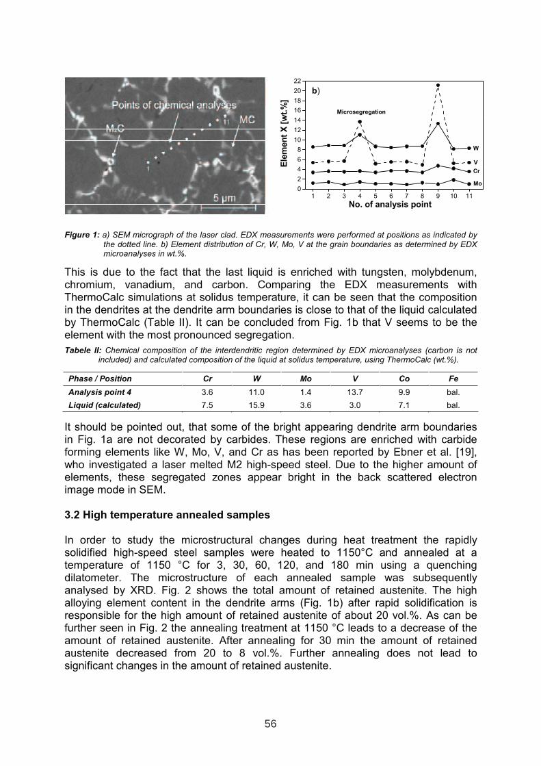
1 2 3 4 5 6 7 8 9 10 110
2
4
6
8
10
12
14
16
18
20
22
b)
Microsegregation
Mo
Cr
V
W
Ele
men
tX
[wt.
%]
No. of analysis point
Figure 1: a) SEM micrograph of the laser clad. EDX measurements were performed at positions as indicated by the dotted line. b) Element distribution of Cr, W, Mo, V at the grain boundaries as determined by EDX microanalyses in wt.%.
This is due to the fact that the last liquid is enriched with tungsten, molybdenum, chromium, vanadium, and carbon. Comparing the EDX measurements with ThermoCalc simulations at solidus temperature, it can be seen that the composition in the dendrites at the dendrite arm boundaries is close to that of the liquid calculated by ThermoCalc (Table II). It can be concluded from Fig. 1b that V seems to be the element with the most pronounced segregation.
Tabele II: Chemical composition of the interdendritic region determined by EDX microanalyses (carbon is not included) and calculated composition of the liquid at solidus temperature, using ThermoCalc (wt.%).
Phase / Position Cr W Mo V Co Fe
Analysis point 4 3.6 11.0 1.4 13.7 9.9 bal.
Liquid (calculated) 7.5 15.9 3.6 3.0 7.1 bal.
It should be pointed out, that some of the bright appearing dendrite arm boundaries in Fig. 1a are not decorated by carbides. These regions are enriched with carbide forming elements like W, Mo, V, and Cr as has been reported by Ebner et al. [19], who investigated a laser melted M2 high-speed steel. Due to the higher amount of elements, these segregated zones appear bright in the back scattered electron image mode in SEM.
3.2 High temperature annealed samples
In order to study the microstructural changes during heat treatment the rapidly solidified high-speed steel samples were heated to 1150°C and annealed at a temperature of 1150 °C for 3, 30, 60, 120, and 180 min using a quenching dilatometer. The microstructure of each annealed sample was subsequently analysed by XRD. Fig. 2 shows the total amount of retained austenite. The high alloying element content in the dendrite arms (Fig. 1b) after rapid solidification is responsible for the high amount of retained austenite of about 20 vol.%. As can be further seen in Fig. 2 the annealing treatment at 1150 °C leads to a decrease of the amount of retained austenite. After annealing for 30 min the amount of retained austenite decreased from 20 to 8 vol.%. Further annealing does not lead to significant changes in the amount of retained austenite.
56
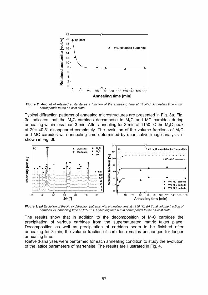
0 10 20 30 60 80 100 120 140 160 180
0
2
4
6
8
10
12
14
16
18
20
22
as-cast
Vf% Retained austenite
Reta
ined
au
ste
nit
e[v
ol.%
]
Annealing time [min]
Figure 2: Amount of retained austenite as a function of the annealing time at 1150°C. Annealing time 0 min corresponds to the as-cast state.
Typical diffraction patterns of annealed microstructures are presented in Fig. 3a. Fig. 3a indicates that the M2C carbides decompose to M6C and MC carbides during annealing within less than 3 min. After annealing for 3 min at 1150 °C the M2C peak
at 2θ= 40.5° disappeared completely. The evolution of the volume fractions of M6Cand MC carbides with annealing time determined by quantitative image analysis isshown in Fig. 3b.
0 10 20 30 60 80 100 120 140 160 180
0
2
4
6
8
10
12
14
ΣΣ MC+MxC measured
Vf% MC carbide
Vf% M
6C carbide
Vf% M
2C carbide
(b) ΣΣ MC+MxC calculated by ThermoCalc
Vo
lum
efr
acti
on
[%]
Annealing time [min]
Figure 3: (a) Evolution of the X-ray diffraction patterns with annealing time at 1150 °C. (b) Total volume fraction of carbides vs. annealing time at 1150 °C. Annealing time 0 min corresponds to the as-cast state.
The results show that in addition to the decomposition of M2C carbides the precipitation of various carbides from the supersaturated matrix takes place. Decomposition as well as precipitation of carbides seem to be finished after annealing for 3 min, the volume fraction of carbides remains unchanged for longer annealing time. Rietveld-analyses were performed for each annealing condition to study the evolution of the lattice parameters of martensite. The results are illustrated in Fig. 4.
30 40 50 60 70 80 90
Austenit
Martensit
180
(a) M2C
M6C
MC
t [min]
120
30
3
60
0
Inte
nsit
y[a
rb.u
.]
2ΘΘ [°]
57
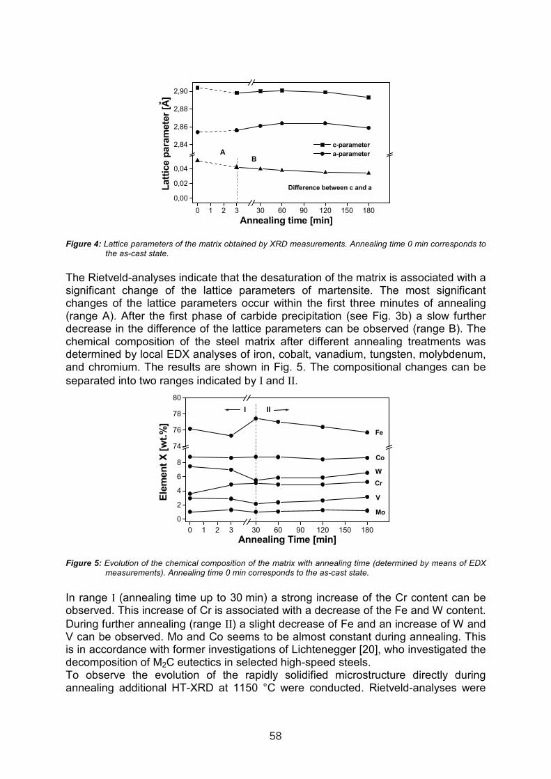
0 1 2 3 30 60 90 120 150 180
0,00
0,02
0,04
2,84
2,86
2,88
2,90
Difference between c and a
c-parameter
a-parameterB
A
Latt
ice
para
mete
r[A
]
Annealing time [min]
Figure 4: Lattice parameters of the matrix obtained by XRD measurements. Annealing time 0 min corresponds to the as-cast state.
The Rietveld-analyses indicate that the desaturation of the matrix is associated with a significant change of the lattice parameters of martensite. The most significant changes of the lattice parameters occur within the first three minutes of annealing (range A). After the first phase of carbide precipitation (see Fig. 3b) a slow further decrease in the difference of the lattice parameters can be observed (range B). The chemical composition of the steel matrix after different annealing treatments wasdetermined by local EDX analyses of iron, cobalt, vanadium, tungsten, molybdenum, and chromium. The results are shown in Fig. 5. The compositional changes can be
separated into two ranges indicated by Ι and ΙΙ.
0 1 2 3 30 60 90 120 150 180
0
2
4
6
8
74
76
78
80
Cr
V
Mo
W
Co
Fe
III
Ele
men
tX
[wt.
%]
Annealing Time [min]
Figure 5: Evolution of the chemical composition of the matrix with annealing time (determined by means of EDX measurements). Annealing time 0 min corresponds to the as-cast state.
In range Ι (annealing time up to 30 min) a strong increase of the Cr content can be observed. This increase of Cr is associated with a decrease of the Fe and W content.
During further annealing (range ΙΙ) a slight decrease of Fe and an increase of W and V can be observed. Mo and Co seems to be almost constant during annealing. This is in accordance with former investigations of Lichtenegger [20], who investigated the decomposition of M2C eutectics in selected high-speed steels. To observe the evolution of the rapidly solidified microstructure directly during annealing additional HT-XRD at 1150 °C were conducted. Rietveld-analyses were
58
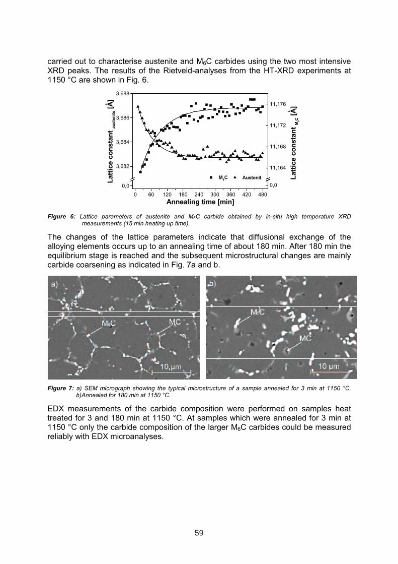
carried out to characterise austenite and M6C carbides using the two most intensive XRD peaks. The results of the Rietveld-analyses from the HT-XRD experiments at 1150 °C are shown in Fig. 6.
0 60 120 180 240 300 360 420 480
0,0
3,682
3,684
3,686
3,688
Austenit Latt
ice
co
nsta
nt
M6C
[A]
Latt
ice
co
nsta
nt
au
ste
nit
e[A
]
Annealing time [min]
0,0
11,164
11,168
11,172
11,176
M6C
o
o
Figure 6: Lattice parameters of austenite and M6C carbide obtained by in-situ high temperature XRD measurements (15 min heating up time).
The changes of the lattice parameters indicate that diffusional exchange of the alloying elements occurs up to an annealing time of about 180 min. After 180 min the equilibrium stage is reached and the subsequent microstructural changes are mainly carbide coarsening as indicated in Fig. 7a and b.
Figure 7: a) SEM micrograph showing the typical microstructure of a sample annealed for 3 min at 1150 °C. b)Annealed for 180 min at 1150 °C.
EDX measurements of the carbide composition were performed on samples heat treated for 3 and 180 min at 1150 °C. At samples which were annealed for 3 min at 1150 °C only the carbide composition of the larger M6C carbides could be measured reliably with EDX microanalyses.
59
Tabele III: Chemical composition of MC and M6C carbides in wt.% determined by EDX microanalyses (carbon is not included) and as calculated by means ThermoCalc.
Phase Cr W Mo V Fe
M6C (annealed 3 min at 1150°) 4.1 47.0 8.5 11.8 28.6
MC (annealed 3 min at 1150°) * * * * *
M6C (annealed 180 min at 1150°) 3.1 54.2 7.7 11.4 23.6
MC (annealed 180 min at 1150°) 2.9 26.9 4.2 63.9 2.1
M6C (calculated at 1150°C) 3.2 58.4 8.6 4.0 25.8
MC (calculated at 1150°C) 8.6 17.8 8.9 63.2 1.5
* Determination of the chemical composition was impossible due to small carbide size.
Comparing the measured composition of MC and M6C after annealing for 180 min at 1150 °C to the calculated with ThermoCalc one (Tab. III) it can be concluded that the chemical compositions correlate well, if the experimental uncertainties are taken into account.
4. CONCLUSIONS
Based on the microstructural analyses and the thermodynamic calculations of the laser cladded HS10-2-5-8 the following conclusions can be drawn: The rapidly solidified microstructure (cooling rate >103 K/s) differs from slowly cooled microstructures mainly in their finer grain size and in a reduced amount of primary carbides. In the as solidified condition the microstructure consists of dendrite arms
and a fine grained eutectic consisting of γ and M2C and MC carbides. Microsegregations within the dendrite arms are still present. Examinations of the microstructure show that annealing of the rapidly solidified high-speed steel at a temperature of 1150 °C for 30 min leads to a significant decrease in the amount of retained austenite. XRD-analyses reveal that the M2C carbides decompose to M6Cand MC carbides within 3 min during annealing at 1150 °C. In addition to the decomposition of the M2C carbides the precipitation of M6C and MC carbides from the supersaturated matrix takes place. These microstructural changes are confirmed by Rietveld–analyses of the lattice parameters of martensite. In-situ HT-XRD measurements indicate that the changes of the chemical composition are completed after annealing at 1150 °C for 3 h. Subsequently only coarsening takes place and the microstructure consists of very small spherical shaped MC and M6C carbides. The microstructural changes measured by HT-XRD correlate well with EDX measurements on heat treated samples.
5. ACKNOWLEDGEMENTS
This work was financially supported by the Österreichische Forschungsförderungsgesellschaft, the Land Steiermark Abt. 3 – Wissenschaft und Forschung, the Steirische Wirtschaftsförderung and the Stadtgemeinde Leoben under the frame of the Kplus competence center programme.
60
References
1. J. Choi, S.K. Choudhuri and J. Mazumder: Journal of Material Science, 35 (2000) 3213–3219.
2. R. Ebner, S. Kleber and H. Hallmann: Practical Metallography Sonderband, 23 (1992) 393–399.
3. A. Tauqir, H. Zaigham, K.H. Hashmi and A.Q. Kahn: Journal of Materials Science, 32 (1997) 465–468.
4. R. Ebner, E. Pfleger, F. Jeglitsch, K. Leban, G. Goldschmidt and A. Schuler: Practical Metallography, 25 (1988) 465-487.
5. Y.-W. Kim, P.R. Strutt and H. Nowotny: Metallurgical Transactions A, 10A (1979) 881–886.
6. P.R. Strutt, H. Nowotny, M. Tuli and B.H. Kear: Materials Science and Engineering, 36 (1978) 217–222.
7. L. Ahman: Metallurgical Transactions A, 15A (1984) 1829 –1835. 8. P.A. Molian and H.S. Rajasekhara: Journal of Materials Science Letters, 5
(1986) 1292–1294. 9. R. Ebner, G. Hackl, E. Brandstätter and F. Jeglitsch: Proc. 1st International High
Speed Steel Conference, Leoben, 1990, 81–91. 10. R. Ebner, E. Brandstätter, G. Hackl and F. Jeglitsch: Practical Metallography
Sonderband, 22 (1991) 569–581. 11. F. Behr, C. Arndt and E. Haberling: Thyssen Edelstahl Technische Berichte, 15
(1989) No. 2, 132–147. 12. C. Stotter, H. Leitner, R. Ebner, P. Ramminger and E. Brandstätter: BHM, 149
(2004) No. 7, 244 –248. 13. Bruker-AXS: “Topas - General profile and structure analysis software for powder
diffraction data”, Bruker-AXS, Karlsruhe, 2000. 14. H.M. Rietveld: Journal Acta Crystallographica, 22 (1967) 151–152. 15. F. Chung and D. Smith: “Industrial Application of X-ray diffraction”, Marcel
Dekker, USA, 2000. 16. R.A. Young: “Introduction to the Rietveld Method”, IUCR Book Series, Oxford
University Press, Oxford, 1993.17. D.G. Morris: Metal Science, 16 (1982) 457–464. 18. J.A. Golezewski and H.F. Fischmeister: Zeitschrift für Metallkunde, 84 (1993)
No. 8, 557–562. 19. R. Ebner: Proc. 2nd Conference on Advanced Materials and Processes,
Cambridge, 1991, Vol. Ι, 115–123. 20. G. Lichtenegger: “Formation and decomposition of the M2C carbides in high-
speed tool steels”, PhD thesis, Montanuniversität Leoben, Leoben, 1995.
61

HIGH TEMPERATURE BRAZING OF HIGH TEC COMPONENTS- A THERMAL PROCESSING WITH SPECIFIC REQUIREMENTS
Ingo Reinkensmeier1, Henkjan Buursen2
1. Bodycote Wärmebehandlung GmbH, Menden, Germany 2. Bodycote Wärmebehandlung GmbH, Diemen, Netherlands
ABSTRACT As a multifunctional joining process, brazing is being applied to an ever-increasing range of components- many applications become only realisable by the use of braz-ing technique. High-strength bonding results through diffusion and alloying proc-esses, which, in many cases, exceed the strength of welded joints. The process High Temperature Brazing under vacuum is cost effective, reproducible and clean solution for many joining operations like components for turbine and aero industry, automo-tive or medical applications. In many cases, it is often the only feasible process. This user-oriented article describes the most recent practical solutions, trends and the latest development in high temperature brazing of High Tec components. Various applications as well as the specific requirements of thermal processing are discussed. In addition to the non destructive testing methods of the joints are illustrated as well.
Keywords: vacuum, vacuum brazing, heat treatment
1 INTRODUCTION
As a multifunctional joining process, brazing is being applied to an ever increasing range of components - many applications can only be realized because of the brazing technique. High-strength bonding results through diffusion and alloying processes, which, in many cases, exceed the strength of welded joints. The High Temperature Brazing process under vacuum is a cost effective, reproducible and clean solution for many joining operations like components for turbine and aero industry, automotive, medical applications and tools and dies. In many cases, it is often the only feasible process. This user-oriented article describes the most recent practical solutions, trends and the latest development in high temperature brazing of High Tec components. Various applications as well as the specific requirements of thermal processing are discussed. In addition to the non destructive testing methods of the joints are illustrated.
1 INTERNATIONAL CONFERENCE ON HEAT TREATMENT
AND SURFACE ENGINEERING OF TOOLS AND DIES
st
Pula, Croatia 08 - 11 June, 2005,
IFHTSE 2005
63
2. RAZING AND HARDENING OF TEMPERED PLASTIC INJECTION
MOULDING TOOLS AND DIES
The combination of vacuum heat treatment and high temperature brazing is de-scribed as an own independent (hybrid) technology. In many cases, you will just suc-ceed in producing competitive and innovative products by using these combination of classic treatments. However, the combination of both processes has only been possi-ble by the use of modern vacuum lines with integrated overpressure gas quenching and multi-directional cooling. In the field of injection moulding tools and dies, these lines take an important position as high performance and flexible means of produc-tion for the hybrid process vacuum brazing technique with integrated heat treatment. Vacuum lines designed that way are working in a pressure area of e. g. 10 bar in the cooling phase up to the high vacuum range of 10-6 mbar during the brazing process. An important example for the application of the combined technology is high tem-perature brazing as well as hardening and tempering of tools and dies for plastics. By the hybrid process, new dimensions in the plastic injection moulding technique could be reached. During the injection moulding process of thermoplastics and thermoset-ting plastics, the tool has to perform the following tasks:
- moulding of the plastic part - heat dissipation at the mould cavity surface (with duroplastics) - heat addition with elastomers - ejection of the readily injection-moulded plastic component
Tools of this type need a well thought-out tempering system in order to configure the cycle time as short as possible, however, without loosing sight of the quality aspect. Here, the process driving factor and therefore the operating efficiency of the tool are based on the cooling time. Especially the temperature of the tool’s wall is having an important influence on the cooling process. Conventional systems with linear drilling technique or the screwing of tool segments with o-ring joints are often coming close to the limits of technical feasibility, if ejectors, breakthroughs and ribs are prescribed by design. The innovative solution of these problems can be found in the process technology vacuum brazing technique with heat treatment integrated into the pro-duction process of injection moulding tools [1]. In this technology, mould inserts are processed in several parts. By metal cutting operations, the cooling channels can be inserted close to the joints. This technology enables the joining of the individual tool segments into a high-strength unit while simultaneously reaching the desired me-chanical/technological values. Typical base materials in this field of applications are 1.2083, 1.2343, 1.2344 and 1.2379. Another example in this field of plastic industry is the brazing and hardening of special dies for plastic granulation. In the described application the brazed prototype with dimensions of ∅ 1200 × 150 mm and a weight
in the near of 1200 kg. The used material is shown in Table I.
64
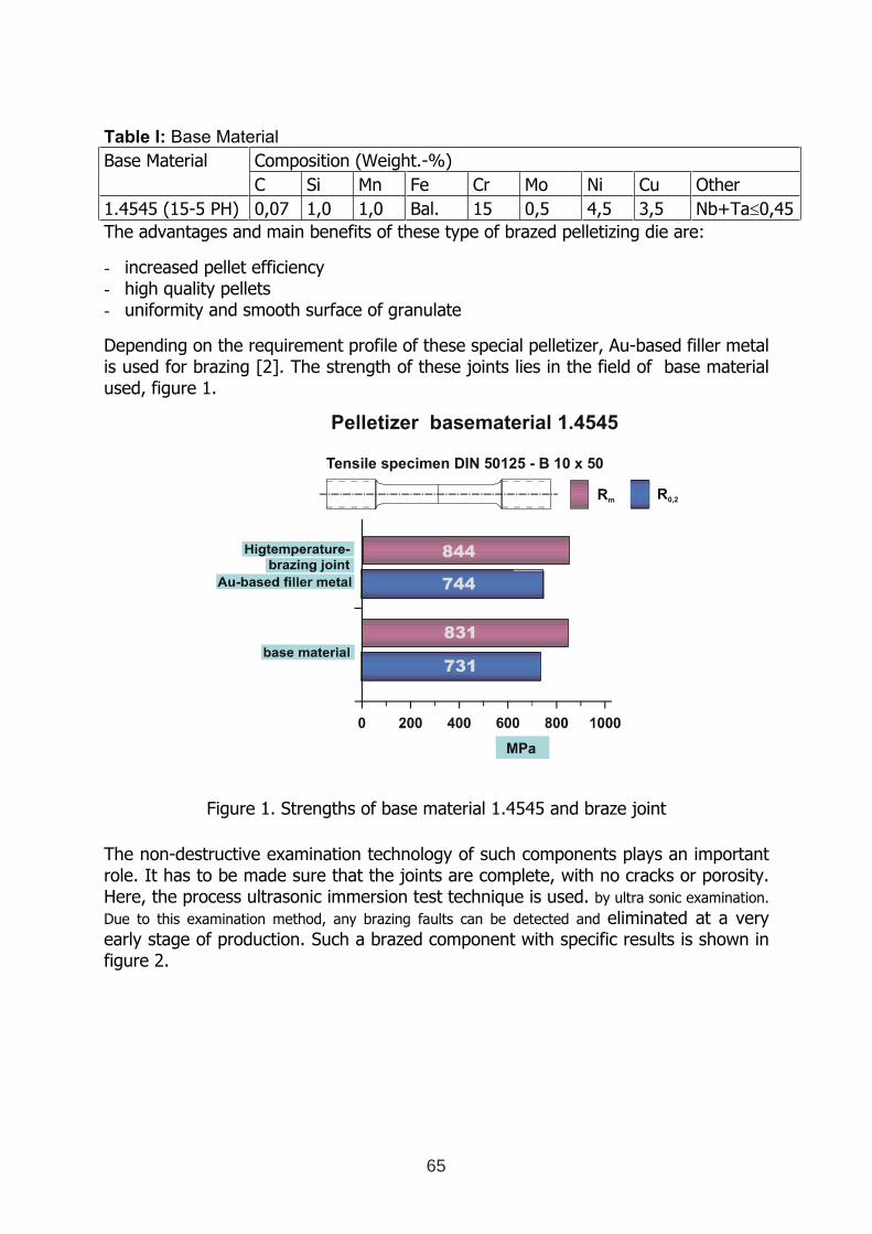
Table I: Base Material
Base Material Composition (Weight.-%)
C Si Mn Fe Cr Mo Ni Cu Other
1.4545 (15-5 PH) 0,07 1,0 1,0 Bal. 15 0,5 4,5 3,5 Nb+Ta≤0,45
The advantages and main benefits of these type of brazed pelletizing die are:
- increased pellet efficiency - high quality pellets - uniformity and smooth surface of granulate
Depending on the requirement profile of these special pelletizer, Au-based filler metal is used for brazing [2]. The strength of these joints lies in the field of base material used, figure 1.
Figure 1. Strengths of base material 1.4545 and braze joint
The non-destructive examination technology of such components plays an important role. It has to be made sure that the joints are complete, with no cracks or porosity. Here, the process ultrasonic immersion test technique is used. by ultra sonic examination.
Due to this examination method, any brazing faults can be detected and eliminated at a very early stage of production. Such a brazed component with specific results is shown in figure 2.
Pelletizer basematerial 1.4545
Rm R0,2
Tensile specimen DIN 50125 - B 10 x 50
731
831
744
844
65
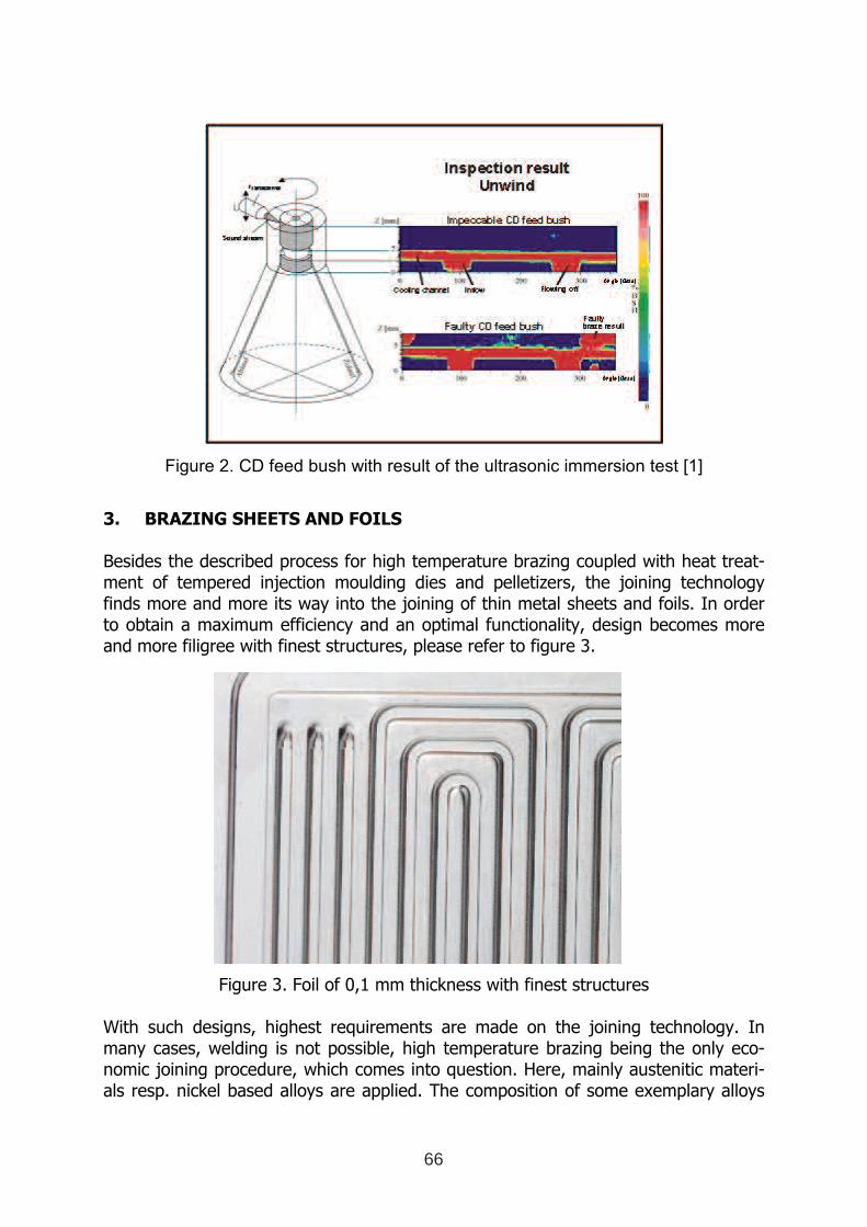
Figure 2. CD feed bush with result of the ultrasonic immersion test [1]
3. BRAZING SHEETS AND FOILS
Besides the described process for high temperature brazing coupled with heat treat-ment of tempered injection moulding dies and pelletizers, the joining technology finds more and more its way into the joining of thin metal sheets and foils. In order to obtain a maximum efficiency and an optimal functionality, design becomes more and more filigree with finest structures, please refer to figure 3.
Figure 3. Foil of 0,1 mm thickness with finest structures
With such designs, highest requirements are made on the joining technology. In many cases, welding is not possible, high temperature brazing being the only eco-nomic joining procedure, which comes into question. Here, mainly austenitic materi-als resp. nickel based alloys are applied. The composition of some exemplary alloys
66
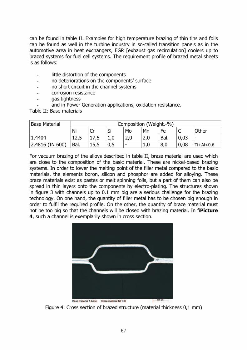
can be found in table II. Examples for high temperature brazing of thin tins and foils can be found as well in the turbine industry in so-called transition panels as in the automotive area in heat exchangers, EGR [exhaust gas recirculation] coolers up to brazed systems for fuel cell systems. The requirement profile of brazed metal sheets is as follows:
- little distortion of the components - no deteriorations on the components’ surface - no short circuit in the channel systems - corrosion resistance - gas tightness - and in Power Generation applications, oxidation resistance.
Table II: Base materials
Composition (Weight.-%) Base Material
Ni Cr Si Mo Mn Fe C Other
1.4404 12,5 17,5 1,0 2,0 2,0 Bal. 0,03 -
2.4816 (IN 600) Bal. 15,5 0,5 - 1,0 8,0 0,08 Ti+Al<0,6
For vacuum brazing of the alloys described in table II, braze material are used which are close to the composition of the basic material. These are nickel-based brazing systems. In order to lower the melting point of the filler metal compared to the basic materials, the elements boron, silicon and phosphor are added for alloying. These braze materials exist as pastes or melt spinning foils, but a part of them can also be spread in thin layers onto the components by electro-plating. The structures shown in figure 3 with channels up to 0.1 mm big are a serious challenge for the brazing technology. On one hand, the quantity of filler metal has to be chosen big enough in order to fulfil the required profile. On the other, the quantity of braze material must not be too big so that the channels will be closed with brazing material. In fiPicture
4, such a channel is exemplarily shown in cross section.
Figure 4: Cross section of brazed structure (material thickness 0,1 mm)
67
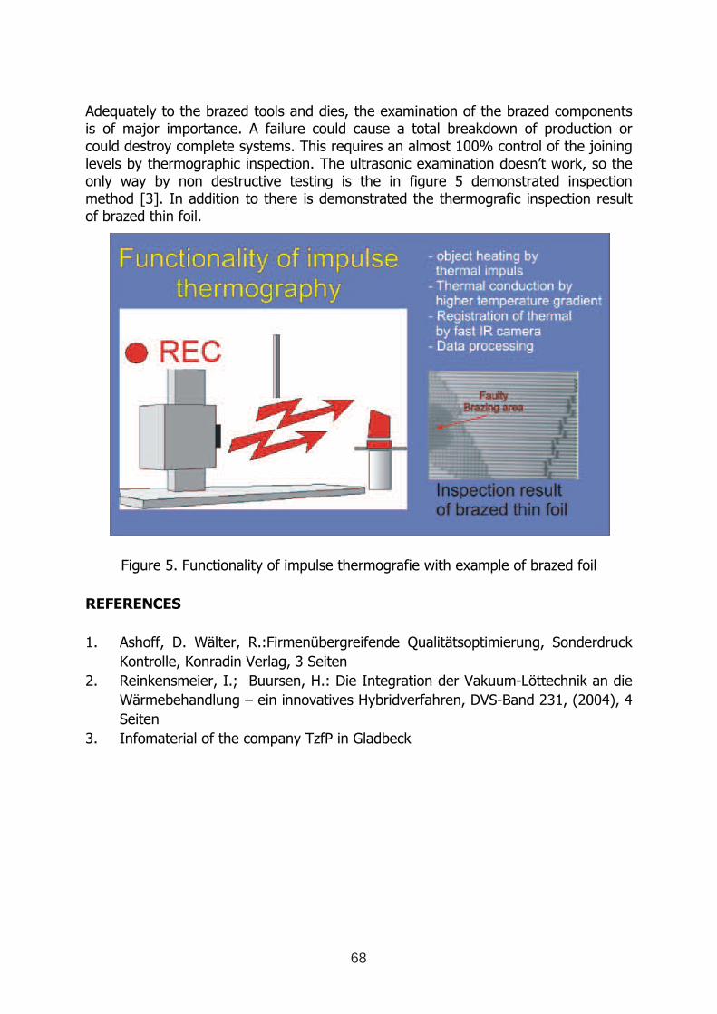
Adequately to the brazed tools and dies, the examination of the brazed components is of major importance. A failure could cause a total breakdown of production or could destroy complete systems. This requires an almost 100% control of the joining levels by thermographic inspection. The ultrasonic examination doesn’t work, so the only way by non destructive testing is the in figure 5 demonstrated inspection method [3]. In addition to there is demonstrated the thermografic inspection result of brazed thin foil.
Figure 5. Functionality of impulse thermografie with example of brazed foil
REFERENCES
1. Ashoff, D. Wälter, R.:Firmenübergreifende Qualitätsoptimierung, Sonderdruck
Kontrolle, Konradin Verlag, 3 Seiten
2. Reinkensmeier, I.; Buursen, H.: Die Integration der Vakuum-Löttechnik an die
Wärmebehandlung – ein innovatives Hybridverfahren, DVS-Band 231, (2004), 4
Seiten
3. Infomaterial of the company TzfP in Gladbeck
68
IMPROVED PRODUCTION OF STEEL PARTS BY INTENSIVE
QUENCHING
N.I Kobasko1, L.C.F. Canale
2, G.E. Totten
3
1. Intensive Technologies Ltd, Kyiv, Ukraine, E-Mail: [email protected]
2. Universidade de Sao Paulo, Sao Paulo, Brasil, E-Mail: [email protected]
3. Portland State University, Portland, USA, E-Mail: [email protected]
ABSTRACT
In this paper, intensive quenching of the half– axles and the conditions which produce
optimal results are reviewed. Service life of axles made of plane carbon steel and intensively
quenched is greater than that achievable by oil quenching of alloy steel. This is explained by
high compressive stresses formed at the surface of the axles. High compressive stresses at the
surface is achieved if cooling rate of steel part is sufficiently high. Intensive quenching
methods can be easily used for quenching steel parts with minimal cross-section dimensional
variations. However, when one section of a steel part is very thin and another is relatively
thick, the use of intensive quenching of a thin part may produce tensile stresses and cracking
because it is not possible to form a uniform hardened martensite shell around the surface of
steel part.
Key words: Intensive quenching, half-axles, compressive stresses, service life
1 INTERNATIONAL CONFERENCE ON HEAT TREATMENT
AND SURFACE ENGINEERING OF TOOLS AND DIES
st
Pula, Croatia 08 - 11 June, 2005,
IFHTSE 2005
69
1. INTRODUCTION
It is generally known that intensive quenching cannot be used to quench alloy and high alloy
steels parts with a very complex shape. In fact, such steel parts often must be quenched in hot
oils. Alternatively, such parts can be intensively quenched if they are made from a very low
hardenability steel. The objective of this paper is to identify the best forms of steel parts that
can be intensively quenched and what criterion should be used to characterize severity of the
intensive cooling process that is necessary to produce optimal compressive stresses at the
surface. This discussion will include several practical examples to validate the approach
proposed.
2. DISCUSSION
2.1. Service Life of Half- Axles
In former Soviet Union (FSU) half –axles were made of alloy steel. However, components that were
previously constructed from alloy steels were subsequently constructed from plain carbon steels using
special equipment equipment for quenching such as that shown in Figure 1.
Optimum stress distribution within a section of steel parts means that high compressive stresses
are formed at the surface and tensile stresses are formed at the core. Since the cooling rate within
the martensitic transformation range is very high during intensive quenching, additional
strengthening of the material is observed. More detailed information about this
superstrengthening phenomenon is discussed in References [1-4]. High compressive stresses at
the surface and additional material strengthening increases significantly the service life of steel
parts (see Table I).
Table I: Fatigue tests of KrAZ truck half- axles [1]
Quenching method Steel grade No of cycles to fracture Note
Oil AISI/SAE 4340 3.8 – 4.6 x 10 5 Half-axles were destroyed
Intensive water spray
cooling
AISI/SAE 1040 3.0 - 3.5 x 10⁶ No fractures observed
Detailed information about optimal stress distribution, service life of truck half-axles and
equipment are provided in Reference [5,6].
70
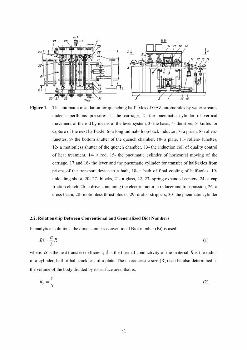
Figure 1. The automatic installation for quenching half-axles of GAZ automobiles by water streams
under superfluous pressure: 1- the carriage, 2- the pneumatic cylinder of vertical
movement of the rod by means of the lever system, 3- the basis, 4- the store, 5- knifes for
capture of the next half-axle, 6- a longitudinal– loop-back inductor, 7- a prism, 8- rollers-
lunettes, 9- the bottom shutter of the quench chamber, 10- a plate, 11- rollers- lunettes,
12- a motionless shutter of the quench chamber, 13- the induction coil of quality control
of heat treatment, 14- a rod, 15- the pneumatic cylinder of horizontal moving of the
carriage, 17 and 16- the lever and the pneumatic cylinder for transfer of half-axles from
prisms of the transport device to a bath, 18- a bath of final cooling of half-axles, 19-
unloading shoot, 20- 27- blocks, 21- a glass, 22, 23- spring-expanded centers, 24- a cap
friction clutch, 26- a drive containing the electric motor, a reducer and transmission, 26- a
cross-beam; 28- motionless thrust blocks; 29- drafts- strippers, 30- the pneumatic cylinder
.
2.2. Relationship Between Conventional and Generalized Biot Numbers
In analytical solutions, the dimensionless conventional Biot number (Bi) is used:
RBiλ
α= (1)
where: α is the heat transfer coefficient; λ is the thermal conductivity of the material; R is the radius
of a cylinder, ball or half thickness of a plate. The characteristic size (RV) can be also determined as
the volume of the body divided by its surface area, that is:
S
VR
V= (2)
71
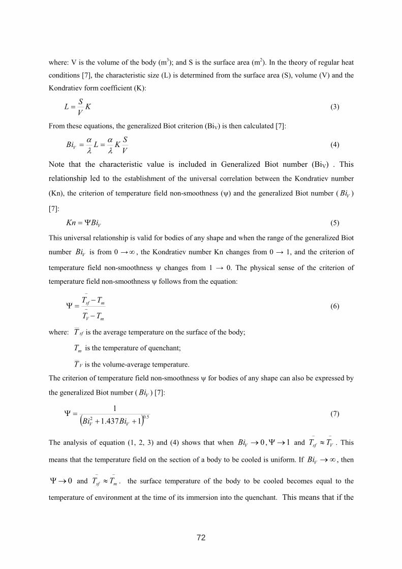
where: V is the volume of the body (m3); and S is the surface area (m2). In the theory of regular heat
conditions [7], the characteristic size (L) is determined from the surface area (S), volume (V) and the
Kondratiev form coefficient (K):
KV
SL = (3)
From these equations, the generalized Biot criterion (BiV) is then calculated [7]:
V
SKLBi
V
λ
α
λ
α== (4)
Note that the characteristic value is included in Generalized Biot number (BiV) . This
relationship led to the establishment of the universal correlation between the Kondratiev number
(Kn), the criterion of temperature field non-smoothness (ψ) and the generalized Biot number (V
Bi )
[7]:
VBiKn Ψ= (5)
This universal relationship is valid for bodies of any shape and when the range of the generalized Biot
numberV
Bi is from 0 →∞ , the Kondratiev number Kn changes from 0 → 1, and the criterion of
temperature field non-smoothness ψ changes from 1 → 0. The physical sense of the criterion of
temperature field non-smoothness ψ follows from the equation:
mV
msf
TT
TT
−
−=Ψ
−
−
(6)
where: sfT is the average temperature on the surface of the body;
mT is the temperature of quenchant;
VT is the volume-average temperature.
The criterion of temperature field non-smoothness ψ for bodies of any shape can also be expressed by
the generalized Biot number (V
Bi ) [7]:
( )5.02 1437.1
1
++
=Ψ
VVBiBi
(7)
The analysis of equation (1, 2, 3) and (4) shows that when 0→V
Bi , 1→Ψ and −−
≈Vsf
TT . This
means that the temperature field on the section of a body to be cooled is uniform. If ∞→V
Bi , then
0→Ψ and −−
≈msf
TT . the surface temperature of the body to be cooled becomes equal to the
temperature of environment at the time of its immersion into the quenchant. This means that if the
72
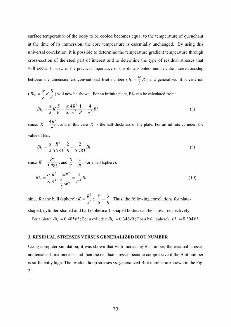
surface temperature of the body to be cooled becomes equal to the temperature of quenchant
at the time of its immersion, the core temperature is essentially unchanged. By using this
universal correlation, it is possible to determine the temperature gradient temperature through
cross-section of the steel part of interest and to determine the type of residual stresses that
will occur. In view of the practical importance of this dimensionless number, the interrelationship
between the dimensionless conventional Biot number ( RBiλ
α= ) and generalized Biot criterion
(V
SKBi
V
λ
α= ) will now be shown. For an infinite plate, BiV can be calculated from:
BiR
R
V
SKBi
V 22
2 414
ππλ
α
λ
α=== (8)
since: 2
24
π
RK = , and in this case R is the half-thickness of the plate. For an infinite cylinder, the
value of BiV:
BiR
RBi
V 783.5
22
783.5
2
=⋅=λ
α(9)
since 783.5
2R
K = ; and RV
S 2= . For a ball (sphere):
Bi
R
RRBi
V 22
2
2
2 3
3
44
ππ
π
πλ
α=⋅= (10)
since for the ball (sphere):2
2
π
RK = ;
RS
V 3= . Thus, the following correlations for plate-
shaped, cylinder-shaped and ball (spherical)- shaped bodies can be shown respectively:
For a plate: BiBiV
405.0= ; For a cylinder: BiBiV
346.0= ; For a ball (sphere): BiBiV
304.0= .
3. RESIDUAL STRESSES VERSUS GENERALIZED BIOT NUMBER
Using computer simulation, it was shown that with increasing Bi number, the residual stresses
are tensile at first increase and then the residual stresses become compressive if the Biot number
is sufficiently high. The residual hoop stresses vs. generalized Biot number are shown in the Fig.
2.
73
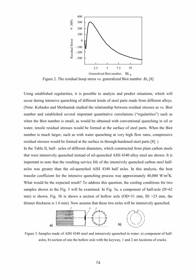
Figure 2. The residual hoop stress vs. generalized Biot numberV
Bi [8]
Using established regularities, it is possible to analyze and predict situations, which will
occur during intensive quenching of different kinds of steel parts made from different alloys.
(Note: Kobasko and Morhuniuk studied the relationship between residual stresses as vs. Biot
number and established several important quantitative correlations (“regularities”) such as
when the Biot number is small, as would be obtained with conventional quenching in oil or
water, tensile residual stresses would be formed at the surface of steel parts. When the Biot
number is much larger, such as with water quenching at very high flow rates, compressive
residual stresses would be formed at the surface in through-hardened steel parts [8]. )
In the Table II, half– axles of different diameters, which constructed from plain carbon steels
that were intensively quenched instead of oil-quenched AISI 4340 alloy steel are shown. It is
important to note that the resulting service life of the intensively quenched carbon steel half-
axles was greater than the oil-quenched AISI 4340 half axles. In this analysis, the heat
transfer coefficient for the intensive quenching process was approximately 40,000 W/m2K.
What would be the expected result? To address this question, the cooling conditions for two
samples shown in the Fig. 3 will be examined. In Fig. 3a, a component of half-axle (D=62
mm) is shown. Fig. 3b is shows a section of hollow axle (OD=31 mm, ID =23 mm, the
thinner thickness is 1.6 mm). Now assume that these two axles will be intensively quenched.
Figure 3. Samples made of AISI 4340 steel and intensively quenched in water: a) component of half-
axles, b) section of one the hollow axle with the keyway, 1 and 2 are locations of cracks.
400
300
200
100
0
- 100
- 200
- 300
2.5 5 7.5 10
Bi νGeneralized Biot number,
74
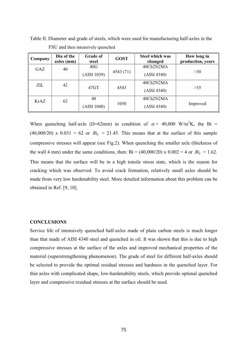
Table II. Diameter and grade of steels, which were used for manufacturing half-axles in the
FSU and then intensively quenched
CompanyDia of the
axles (mm)
Grade of
steel GOST
Steel which was
changed
How long in
production, years
GAZ 4040G
(AISI 1039)4543 (71)
40Ch2N2MA
(AISI 4340) >30
ZIL 4247GT 4543
40Ch2N2MA
(AISI 4340) >35
KrAZ 6240
(AISI 1040) 1050
40Ch2N2MA
(AISI 4340) Improved
When quenching half-axle (D=62mm) in condition of α = 40,000 W/m2K, the Bi =
(40,000/20) x 0.031 = 62 or V
Bi = 21.45. This means that at the surface of this sample
compressive stresses will appear (see Fig.2). When quenching the smaller axle (thickness of
the wall 4 mm) under the same conditions, then: Bi = (40,000/20) x 0.002 = 4 or V
Bi = 1.62.
This means that the surface will be in a high tensile stress state, which is the reason for
cracking which was observed. To avoid crack formation, relatively small axles should be
made from very low hardenability steel. More detailed information about this problem can be
obtained in Ref. [9, 10].
CONCLUSIONS
Service life of intensively quenched half-axles made of plain carbon steels is much longer
than that made of AISI 4340 steel and quenched in oil. It was shown that this is due to high
compressive stresses at the surface of the axles and improved mechanical properties of the
material (superstrengthening phenomenon). The grade of steel for different half-axles should
be selected to provide the optimal residual stresses and hardness in the quenched layer. For
thin axles with complicated shape, low-hardenability steels, which provide optimal quenched
layer and compressive residual stresses at the surface should be used.
75
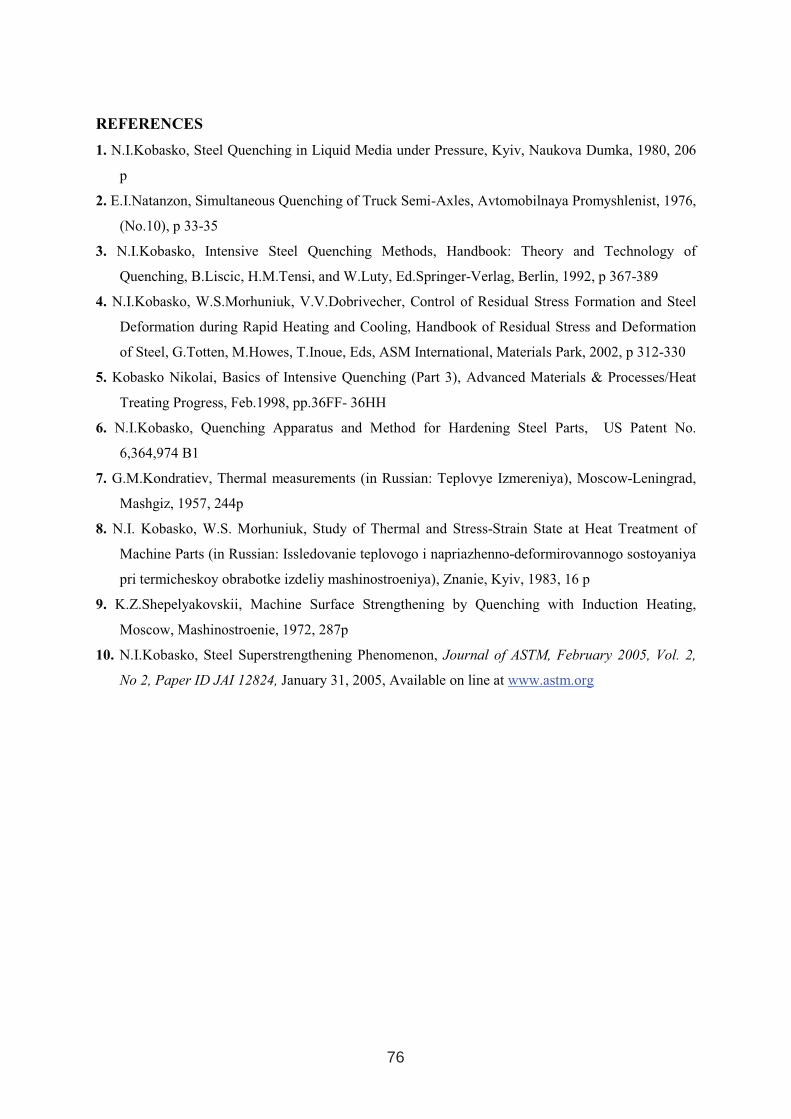
REFERENCES
1. N.I.Kobasko, Steel Quenching in Liquid Media under Pressure, Kyiv, Naukova Dumka, 1980, 206
p
2. E.I.Natanzon, Simultaneous Quenching of Truck Semi-Axles, Avtomobilnaya Promyshlenist, 1976,
(No.10), p 33-35
3. N.I.Kobasko, Intensive Steel Quenching Methods, Handbook: Theory and Technology of
Quenching, B.Liscic, H.M.Tensi, and W.Luty, Ed.Springer-Verlag, Berlin, 1992, p 367-389
4. N.I.Kobasko, W.S.Morhuniuk, V.V.Dobrivecher, Control of Residual Stress Formation and Steel
Deformation during Rapid Heating and Cooling, Handbook of Residual Stress and Deformation
of Steel, G.Totten, M.Howes, T.Inoue, Eds, ASM International, Materials Park, 2002, p 312-330
5. Kobasko Nikolai, Basics of Intensive Quenching (Part 3), Advanced Materials & Processes/Heat
Treating Progress, Feb.1998, pp.36FF- 36HH
6. N.I.Kobasko, Quenching Apparatus and Method for Hardening Steel Parts, US Patent No.
6,364,974 B1
7. G.M.Kondratiev, Thermal measurements (in Russian: Teplovye Izmereniya), Moscow-Leningrad,
Mashgiz, 1957, 244p
8. N.I. Kobasko, W.S. Morhuniuk, Study of Thermal and Stress-Strain State at Heat Treatment of
Machine Parts (in Russian: Issledovanie teplovogo i napriazhenno-deformirovannogo sostoyaniya
pri termicheskoy obrabotke izdeliy mashinostroeniya), Znanie, Kyiv, 1983, 16 p
9. K.Z.Shepelyakovskii, Machine Surface Strengthening by Quenching with Induction Heating,
Moscow, Mashinostroenie, 1972, 287p
10. N.I.Kobasko, Steel Superstrengthening Phenomenon, Journal of ASTM, February 2005, Vol. 2,
No 2, Paper ID JAI 12824, January 31, 2005, Available on line at www.astm.org
76

THE USE OF A NEW TYPE OF LARGE VACUUM BATCH FURNACEFOR THE HEAT TREATMENT OF MOULDS AND DIES
Th. Wingens, Ipsen International Inc., Rockford/US B. Edenhofer, Ipsen International GmbH, Kleve/D
O. Irretier, Ipsen International GmbH, Kleve/D
ABSTRACT
The primary focus in vacuum heat treating of die cast dies is to reduce distortion, while obtaining a smooth surface finish with no post cleaning needed and easyprocess control. The slower gas quenching reduced distortion, but special larger diesshowed grain boundary precipitation with shorter die life. With the increased use of high-pressure gas quenching and faster quench rates for moulds and dies, the quality of heat treatment has improved significantly over the last ten years. With quicker quench rates, distortion and post machining increased, however, the risk of quench cracking was accepted in return for the improvement in lifetime. This paper discusses the vacuum heat treating of moulds and dies (over 5 metric tons) in the newly developed SuperTurbo™ vacuum furnace with 15 bar nitrogen gas quench combined with directional cooling.
KEY WORDS: heat treating, vacuum hardening, moulds and dies, high-pressure gas quenching
1. INTRODUCTION
With the introduction of vacuum heat treating of dies, the demands in the 80’s and 90’s were focused on distortion control especially on large H13 (1.2343) die inserts, since minimizing distortion saved money on post machining. The downside was that low distortion was mostly realized through a very slow gas quench with less than 30ºF (17 ºC) per minute, which consequently resulted in the precipitation of grain boundary carbides and a shorter die life due to reduced impact toughness (Fig. 1, 2).
Figure 1: Inacceptable H13 microsctructure Figure 2: Acceptable H13 mictostructure
1 INTERNATIONAL CONFERENCE ON HEAT TREATMENT
AND SURFACE ENGINEERING OF TOOLS AND DIES
st
Pula, Croatia 08 - 11 June, 2005,
IFHTSE 2005
77
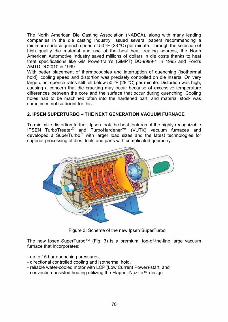
The North American Die Casting Association (NADCA), along with many leading companies in the die casting industry, issued several papers recommending a minimum surface quench speed of 50 ºF (28 ºC) per minute. Through the selection of high quality die material and use of the best heat treating sources, the North American Automotive Industry saved millions of dollars in die costs thanks to heat treat specifications like GM Powertrain’s (GMPT) DC-9999-1 in 1995 and Ford’s AMTD DC2010 in 1999. With better placement of thermocouples and interruption of quenching (isothermal hold), cooling speed and distortion was precisely controlled on die inserts. On verylarge dies, quench rates still fell below 50 ºF (28 ºC) per minute. Distortion was high, causing a concern that die cracking may occur because of excessive temperature differences between the core and the surface that occur during quenching. Cooling holes had to be machined often into the hardened part, and material stock was sometimes not sufficient for this.
2. IPSEN SUPERTURBO – THE NEXT GENERATION VACUUM FURNACE
To minimize distortion further, Ipsen took the best features of the highly recognizable IPSEN TurboTreater® and TurboHardener™ (VUTK) vacuum furnaces and developed a SuperTurbo™ with larger load sizes and the latest technologies for superior processing of dies, tools and parts with complicated geometry.
Figure 3: Scheme of the new Ipsen SuperTurbo
The new Ipsen SuperTurbo™ (Fig. 3) is a premium, top-of-the-line large vacuum furnace that incorporates:
- up to 15 bar quenching pressures, - directional controlled cooling and isothermal hold. - reliable water-cooled motor with LCP (Low Current Power)-start, and - convection-assisted heating utilizing the Flapper Nozzle™ design.
78
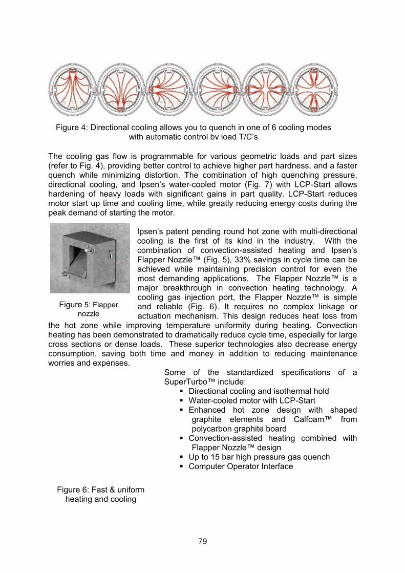
Figure 5: Flapper
nozzle
The cooling gas flow is programmable for various geometric loads and part sizes(refer to Fig. 4), providing better control to achieve higher part hardness, and a faster quench while minimizing distortion. The combination of high quenching pressure, directional cooling, and Ipsen’s water-cooled motor (Fig. 7) with LCP-Start allowshardening of heavy loads with significant gains in part quality. LCP-Start reduces motor start up time and cooling time, while greatly reducing energy costs during the peak demand of starting the motor.
Ipsen’s patent pending round hot zone with multi-directional cooling is the first of its kind in the industry. With the combination of convection-assisted heating and Ipsen’s Flapper Nozzle™ (Fig. 5), 33% savings in cycle time can be achieved while maintaining precision control for even the most demanding applications. The Flapper Nozzle™ is a major breakthrough in convection heating technology. A cooling gas injection port, the Flapper Nozzle™ is simple and reliable (Fig. 6). It requires no complex linkage or actuation mechanism. This design reduces heat loss from
the hot zone while improving temperature uniformity during heating. Convection heating has been demonstrated to dramatically reduce cycle time, especially for large cross sections or dense loads. These superior technologies also decrease energyconsumption, saving both time and money in addition to reducing maintenance worries and expenses.
Some of the standardized specifications of a SuperTurbo™ include:
Directional cooling and isothermal hold Water-cooled motor with LCP-Start Enhanced hot zone design with shaped
graphite elements and Calfoam™ from polycarbon graphite board
Convection-assisted heating combined with Flapper Nozzle™ design
Up to 15 bar high pressure gas quench Computer Operator Interface
Figure 4: Directional cooling allows you to quench in one of 6 cooling modes with automatic control by load T/C’s
Figure 6: Fast & uniform heating and cooling
79
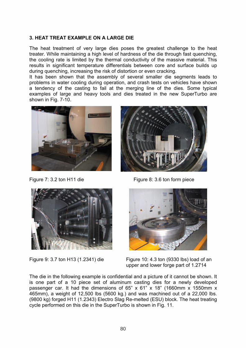
3. HEAT TREAT EXAMPLE ON A LARGE DIE
The heat treatment of very large dies poses the greatest challenge to the heat treater. While maintaining a high level of hardness of the die through fast quenching, the cooling rate is limited by the thermal conductivity of the massive material. Thisresults in significant temperature differentials between core and surface builds up during quenching, increasing the risk of distortion or even cracking. It has been shown that the assembly of several smaller die segments leads to problems in water cooling during operation, and crash tests on vehicles have shown a tendency of the casting to fail at the merging line of the dies. Some typical examples of large and heavy tools and dies treated in the new SuperTurbo are shown in Fig. 7-10.
Figure 7: 3.2 ton H11 die Figure 8: 3.6 ton form piece
Figure 9: 3.7 ton H13 (1.2341) die Figure 10: 4.3 ton (9330 lbs) load of an upper and lower forge part of 1.2714
The die in the following example is confidential and a picture of it cannot be shown. It is one part of a 10 piece set of aluminum casting dies for a newly developed passenger car. It had the dimensions of 65” x 61” x 18” (1660mm x 1550mm x 465mm), a weight of 12,500 lbs (5600 kg.) and was machined out of a 22,000 lbs. (9800 kg) forged H11 (1.2343) Electro Slag Re-melted (ESU) block. The heat treating cycle performed on this die in the SuperTurbo is shown in Fig. 11.
80
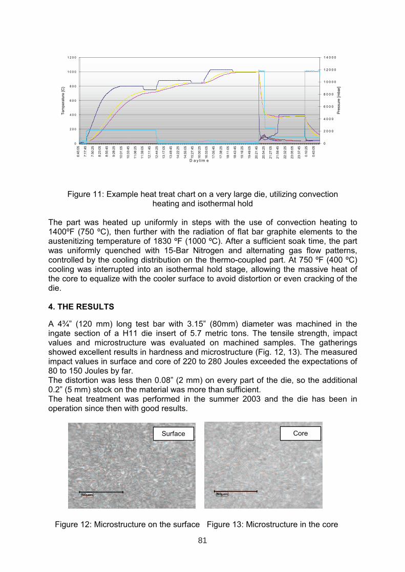
Figure 11: Example heat treat chart on a very large die, utilizing convection heating and isothermal hold
The part was heated up uniformly in steps with the use of convection heating to 1400ºF (750 ºC), then further with the radiation of flat bar graphite elements to the austenitizing temperature of 1830 ºF (1000 ºC). After a sufficient soak time, the part was uniformly quenched with 15-Bar Nitrogen and alternating gas flow patterns, controlled by the cooling distribution on the thermo-coupled part. At 750 ºF (400 ºC) cooling was interrupted into an isothermal hold stage, allowing the massive heat of the core to equalize with the cooler surface to avoid distortion or even cracking of the die.
4. THE RESULTS
A 4¾” (120 mm) long test bar with 3.15” (80mm) diameter was machined in the ingate section of a H11 die insert of 5.7 metric tons. The tensile strength, impact values and microstructure was evaluated on machined samples. The gatheringsshowed excellent results in hardness and microstructure (Fig. 12, 13). The measured impact values in surface and core of 220 to 280 Joules exceeded the expectations of 80 to 150 Joules by far. The distortion was less then 0.08” (2 mm) on every part of the die, so the additional 0.2” (5 mm) stock on the material was more than sufficient. The heat treatment was performed in the summer 2003 and the die has been in operation since then with good results.
Cor
Figure 12: Microstructure on the surface Figure 13: Microstructure in the core
0
2 0 0
4 0 0
6 0 0
8 0 0
1 0 0 0
1 2 0 0
6:4
5:0
5
7:1
7:4
5
7:5
0:2
5
8:2
3:0
5
8:5
5:4
5
9:2
8:2
5
10:0
1:0
5
10:3
3:4
5
11:0
6:2
5
11:3
9:0
5
12:1
1:4
5
12:4
4:2
5
13:1
7:0
5
13:4
9:4
5
14:2
2:2
5
14:5
5:0
5
15:2
7:4
5
16:0
0:2
5
16:3
3:0
5
17:0
5:4
5
17:3
8:2
5
18:1
1:0
5
18:4
3:4
5
19:1
6:2
5
19:4
9:0
5
20:2
1:4
5
20:5
4:2
5
21:2
7:0
5
21:5
9:4
5
22:3
2:2
5
23:0
5:0
5
23:3
7:4
5
0:1
0:2
5
0:4
3:0
5
D a y t im e
Tem
pera
ture
[C
0
2 0 0 0
4 0 0 0
6 0 0 0
8 0 0 0
1 0 0 0 0
1 2 0 0 0
1 4 0 0 0
Pre
ssure
[mbar]
Surface Core
81
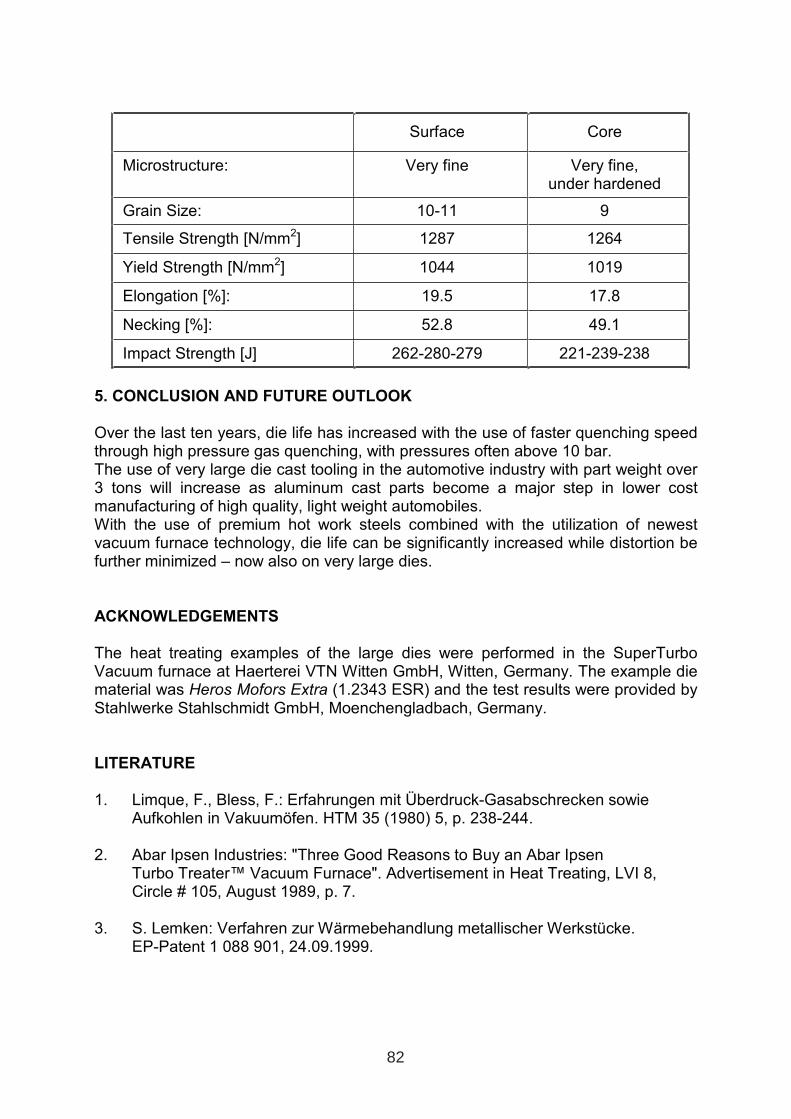
Surface Core
Microstructure: Very fine Very fine, under hardened
Grain Size: 10-11 9
Tensile Strength [N/mm2] 1287 1264
Yield Strength [N/mm2] 1044 1019
Elongation [%]: 19.5 17.8
Necking [%]: 52.8 49.1
Impact Strength [J] 262-280-279 221-239-238
5. CONCLUSION AND FUTURE OUTLOOK
Over the last ten years, die life has increased with the use of faster quenching speed through high pressure gas quenching, with pressures often above 10 bar. The use of very large die cast tooling in the automotive industry with part weight over 3 tons will increase as aluminum cast parts become a major step in lower cost manufacturing of high quality, light weight automobiles. With the use of premium hot work steels combined with the utilization of newest vacuum furnace technology, die life can be significantly increased while distortion be further minimized – now also on very large dies.
ACKNOWLEDGEMENTS
The heat treating examples of the large dies were performed in the SuperTurbo Vacuum furnace at Haerterei VTN Witten GmbH, Witten, Germany. The example die material was Heros Mofors Extra (1.2343 ESR) and the test results were provided byStahlwerke Stahlschmidt GmbH, Moenchengladbach, Germany.
LITERATURE
1. Limque, F., Bless, F.: Erfahrungen mit Überdruck-Gasabschrecken sowie Aufkohlen in Vakuumöfen. HTM 35 (1980) 5, p. 238-244.
2. Abar Ipsen Industries: "Three Good Reasons to Buy an Abar Ipsen Turbo Treater™ Vacuum Furnace". Advertisement in Heat Treating, LVI 8, Circle # 105, August 1989, p. 7.
3. S. Lemken: Verfahren zur Wärmebehandlung metallischer Werkstücke. EP-Patent 1 088 901, 24.09.1999.
82
SINGLE AND MULTI-CHAMBER VACUUM FURNACES FOR TOOLS AND DIES HEAT TREATMENT
Dr. Dariusz Siniarski - Lodz Technical University
MSc. Maciej Korecki - Seco/Warwick ABSTRACT In recent times there has been a dynamic growth in the technology of heat treatment and thermo-chemical treatment under vacuum. The driving force behind this phenomenon is that users and manufacturers are focussing more on the efficiency, energy saving capability and environmental acceptability of installations and technology whilst paying fundamental attention to quality and reliability. Initially vacuum technology was the domain of the most exacting industries such as the specialist space or aviation sectors, but over time, in the course of the development of vacuum engineering and the spread of materials technologies it has started to turn up more and more frequently in general industry and commercial heat treatment plants. The following article presents the technology and the Seco/Warwick vacuum furnaces dedicated to the tools and dies industry based on high pressure gas quenching as well as some aspect of the innovative FineCarb® vacuum carburizing process. Key words: Vacuum furnace, high pressure gas quenching, vacuum carburizing 1. GAS QUENCHING Vacuum heat treatment is in competition with traditional technology. It is unrivalled as regards the purity of the protective atmosphere (vacuum) and the technological efficiency of the heating system and quality of temperature regulation. Furthermore there are significantly fewer problems with cooling carried out using gas (nitrogen, argon) by comparison with traditional technologies based on fluids (water, oil, salts). Gas in normal conditions is the slowest cooling medium, resulting from its property, but its use brings measurable benefits. Gas cooling is uniform and proceeds in a single phase (by convection) and can be controlled over a wide range, which has a positive effect on the technological results, including minimising the deformations. In addition the investment and operating costs for a gas installation are very competitive in terms of the general accessibility of gas (including liquid gas) and hire of the installation and to a large extent through washing equipment being dispensed with. Gas also scores positively with regard to the environment over oils and salts, whose application is much more limited and their use expensive. [5] Today a major challenge for furnace manufacturers is to increase the efficiency of cooling with a view to mastering the technology of hardening successive grades of steel and sizes of charges, traditionally cooled in liquids, on the assumption that the cooling agent is gas, with regard among other things for its environmental credentials. The virtues of gas cooling, apart from the environmental benefits, apply above all to the technological and economic results,
1 INTERNATIONAL CONFERENCE ON HEAT TREATMENT
AND SURFACE ENGINEERING OF TOOLS AND DIES
st
Pula, Croatia 08 - 11 June, 2005,
IFHTSE 2005
83
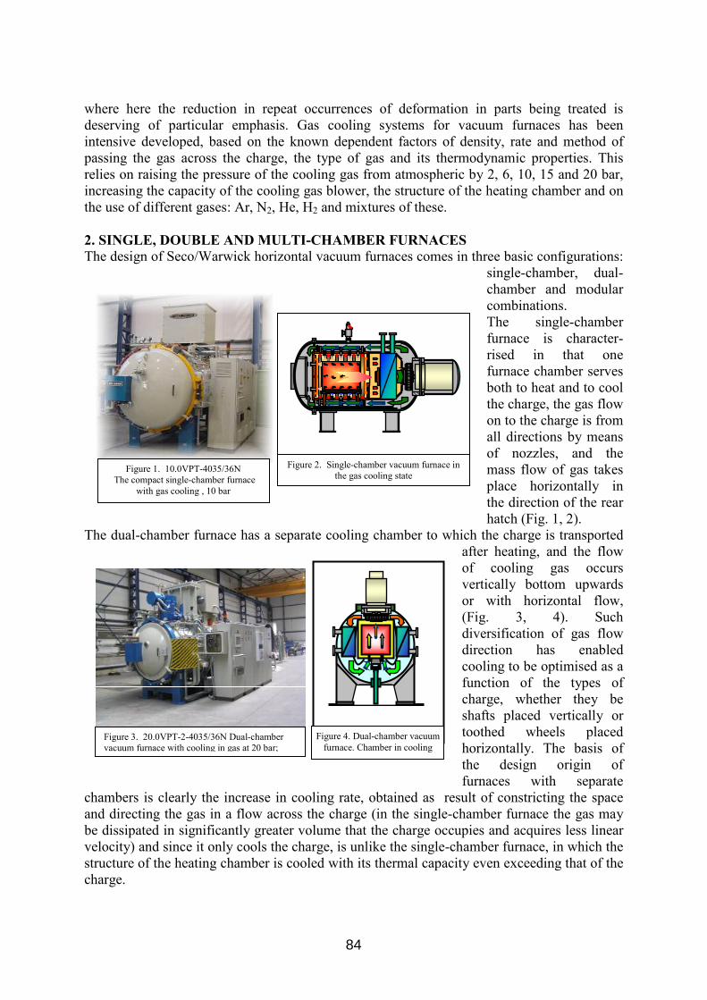
where here the reduction in repeat occurrences of deformation in parts being treated is deserving of particular emphasis. Gas cooling systems for vacuum furnaces has been intensive developed, based on the known dependent factors of density, rate and method of passing the gas across the charge, the type of gas and its thermodynamic properties. This relies on raising the pressure of the cooling gas from atmospheric by 2, 6, 10, 15 and 20 bar, increasing the capacity of the cooling gas blower, the structure of the heating chamber and on the use of different gases: Ar, N2, He, H2 and mixtures of these. 2. SINGLE, DOUBLE AND MULTI-CHAMBER FURNACES The design of Seco/Warwick horizontal vacuum furnaces comes in three basic configurations:
single-chamber, dual-chamber and modular combinations. The single-chamber furnace is character-rised in that one furnace chamber serves both to heat and to cool the charge, the gas flow on to the charge is from all directions by means of nozzles, and the mass flow of gas takes place horizontally in the direction of the rear hatch (Fig. 1, 2).
The dual-chamber furnace has a separate cooling chamber to which the charge is transported after heating, and the flow of cooling gas occurs vertically bottom upwards or with horizontal flow, (Fig. 3, 4). Such diversification of gas flow direction has enabled cooling to be optimised as a function of the types of charge, whether they be shafts placed vertically or toothed wheels placed horizontally. The basis of the design origin of furnaces with separate
chambers is clearly the increase in cooling rate, obtained as result of constricting the space and directing the gas in a flow across the charge (in the single-chamber furnace the gas may be dissipated in significantly greater volume that the charge occupies and acquires less linear velocity) and since it only cools the charge, is unlike the single-chamber furnace, in which the structure of the heating chamber is cooled with its thermal capacity even exceeding that of the charge.
Figure 4. Dual-chamber vacuum furnace. Chamber in cooling
Figure 3. 20.0VPT-2-4035/36N Dual-chamber vacuum furnace with cooling in gas at 20 bar;
Figure 1. 10.0VPT-4035/36N The compact single-chamber furnace
with gas cooling , 10 bar
Figure 2. Single-chamber vacuum furnace in the gas cooling state
84
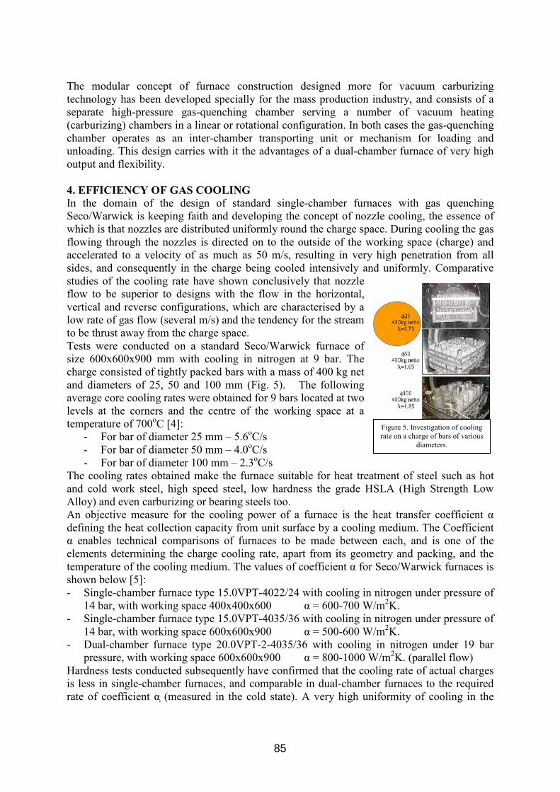
The modular concept of furnace construction designed more for vacuum carburizing technology has been developed specially for the mass production industry, and consists of a separate high-pressure gas-quenching chamber serving a number of vacuum heating (carburizing) chambers in a linear or rotational configuration. In both cases the gas-quenching chamber operates as an inter-chamber transporting unit or mechanism for loading and unloading. This design carries with it the advantages of a dual-chamber furnace of very high output and flexibility. 4. EFFICIENCY OF GAS COOLING In the domain of the design of standard single-chamber furnaces with gas quenching Seco/Warwick is keeping faith and developing the concept of nozzle cooling, the essence of which is that nozzles are distributed uniformly round the charge space. During cooling the gas flowing through the nozzles is directed on to the outside of the working space (charge) and accelerated to a velocity of as much as 50 m/s, resulting in very high penetration from all sides, and consequently in the charge being cooled intensively and uniformly. Comparative studies of the cooling rate have shown conclusively that nozzle flow to be superior to designs with the flow in the horizontal, vertical and reverse configurations, which are characterised by a low rate of gas flow (several m/s) and the tendency for the stream to be thrust away from the charge space. Tests were conducted on a standard Seco/Warwick furnace of size 600x600x900 mm with cooling in nitrogen at 9 bar. The charge consisted of tightly packed bars with a mass of 400 kg net and diameters of 25, 50 and 100 mm (Fig. 5). The following average core cooling rates were obtained for 9 bars located at two levels at the corners and the centre of the working space at a temperature of 700oC [4]:
- For bar of diameter 25 mm – 5.6oC/s - For bar of diameter 50 mm – 4.0oC/s - For bar of diameter 100 mm – 2.3oC/s
The cooling rates obtained make the furnace suitable for heat treatment of steel such as hot and cold work steel, high speed steel, low hardness the grade HSLA (High Strength Low Alloy) and even carburizing or bearing steels too. An objective measure for the cooling power of a furnace is the heat transfer coefficient αdefining the heat collection capacity from unit surface by a cooling medium. The Coefficient α enables technical comparisons of furnaces to be made between each, and is one of the elements determining the charge cooling rate, apart from its geometry and packing, and the temperature of the cooling medium. The values of coefficient α for Seco/Warwick furnaces is shown below [5]: - Single-chamber furnace type 15.0VPT-4022/24 with cooling in nitrogen under pressure of
14 bar, with working space 400x400x600 α = 600-700 W/m2K. - Single-chamber furnace type 15.0VPT-4035/36 with cooling in nitrogen under pressure of
14 bar, with working space 600x600x900 α = 500-600 W/m2K. - Dual-chamber furnace type 20.0VPT-2-4035/36 with cooling in nitrogen under 19 bar
pressure, with working space 600x600x900 α = 800-1000 W/m2K. (parallel flow) Hardness tests conducted subsequently have confirmed that the cooling rate of actual charges is less in single-chamber furnaces, and comparable in dual-chamber furnaces to the required rate of coefficient α D(measured in the cold state). A very high uniformity of cooling in the
Figure 5. Investigation of cooling rate on a charge of bars of various
diameters.
85
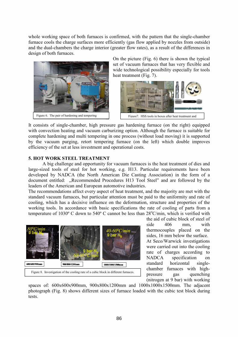
Figure 6. The pair of hardening and tempering Figure7. HSS tools in boxes after heat treatment and
whole working space of both furnaces is confirmed, with the pattern that the single-chamber furnace cools the charge surfaces more efficiently (gas flow applied by nozzles from outside) and the dual-chambers the charge interior (greater flow rates), as a result of the differences in design of both furnaces.
On the picture (Fig. 6) there is shown the typical set of vacuum furnaces that has very flexible and wide technological possibility especially for tools heat treatment (Fig. 7).
It consists of single-chamber, high pressure gas hardening furnace (on the right) equipped with convection heating and vacuum carburizing option. Although the furnace is suitable for complete hardening and multi tempering in one process (without load moving) it is supported by the vacuum purging, retort tempering furnace (on the left) which double improves efficiency of the set at less investment and operational costs. 5. HOT WORK STEEL TREATMENT
A big challenge and opportunity for vacuum furnaces is the heat treatment of dies and large-sized tools of steel for hot working, e.g. H13. Particular requirements have been developed by NADCA (the North American Die Casting Association) in the form of a document entitled: „Recommended Procedures H13 Tool Steel” and are followed by the leaders of the American and European automotive industries. The recommendations affect every aspect of heat treatment, and the majority are met with the standard vacuum furnaces, but particular attention must be paid to the uniformity and rate of cooling, which has a decisive influence on the deformation, structure and properties of the working tools. In accordance with basic specifications the rate of cooling of parts from a temperature of 1030º C down to 540º C cannot be less than 28oC/min, which is verified with
the aid of cubic block of steel of side 406 mm, with thermocouples placed on the sides, 16 mm below the surface. At Seco/Warwick investigations were carried out into the cooling rate of charges according to NADCA specification on standard horizontal single-chamber furnaces with high-pressure gas quenching (nitrogen at 9 bar) with working
spaces of: 600x600x900mm, 900x800x1200mm and 1000x1000x1500mm. The adjacent photograph (Fig. 8) shows different sizes of furnace loaded with the cubic test block during tests.
600/600/900mm 900/800/1200mm 1000/1000/1500mm
800C/min
60-80 0C/min
40-600C/min9 bar N2
9 bar N2
9 bar N2
600/600/900mm 900/800/1200mm 1000/1000/1500mm
800C/min
60-80 0C/min
40-600C/min9 bar N2
9 bar N2
9 bar N2
Figure 8. Investigation of the cooling rate of a cubic block in different furnaces.
86
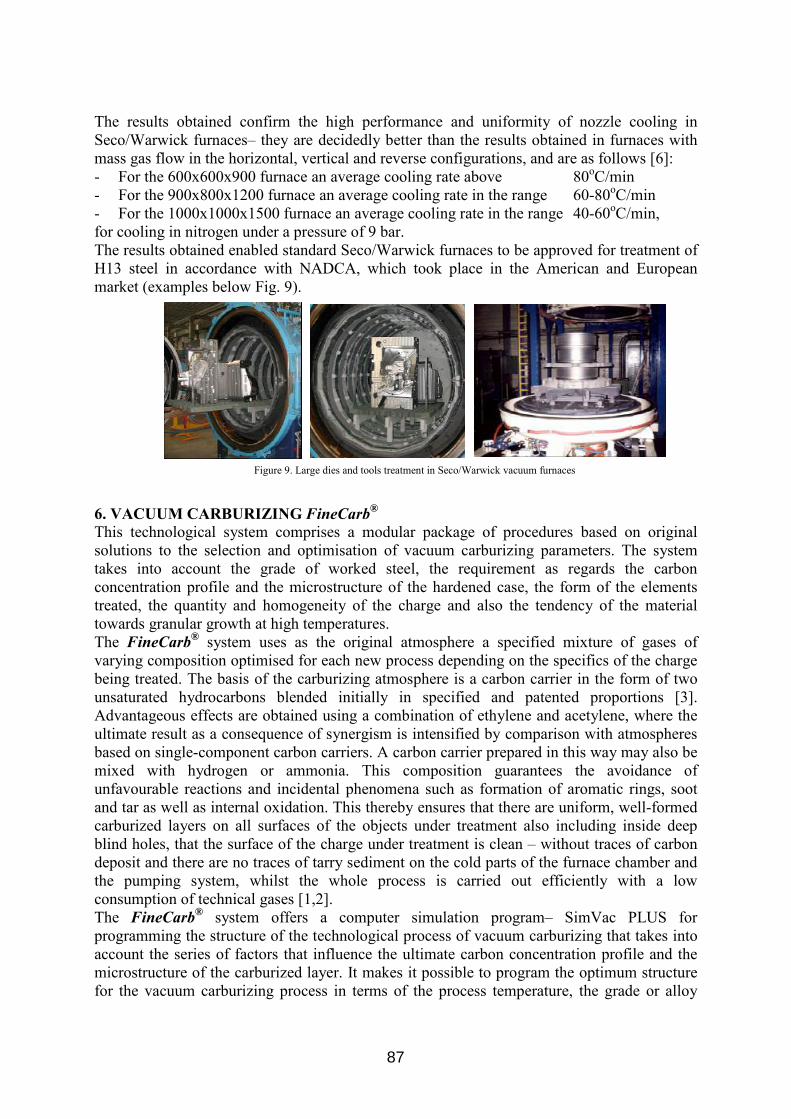
The results obtained confirm the high performance and uniformity of nozzle cooling in Seco/Warwick furnaces– they are decidedly better than the results obtained in furnaces with mass gas flow in the horizontal, vertical and reverse configurations, and are as follows [6]: - For the 600x600x900 furnace an average cooling rate above 80oC/min - For the 900x800x1200 furnace an average cooling rate in the range 60-80oC/min - For the 1000x1000x1500 furnace an average cooling rate in the range 40-60oC/min, for cooling in nitrogen under a pressure of 9 bar. The results obtained enabled standard Seco/Warwick furnaces to be approved for treatment of H13 steel in accordance with NADCA, which took place in the American and European market (examples below Fig. 9).
6. VACUUM CARBURIZING FineCarb®
This technological system comprises a modular package of procedures based on original solutions to the selection and optimisation of vacuum carburizing parameters. The system takes into account the grade of worked steel, the requirement as regards the carbon concentration profile and the microstructure of the hardened case, the form of the elements treated, the quantity and homogeneity of the charge and also the tendency of the material towards granular growth at high temperatures. The FineCarb® system uses as the original atmosphere a specified mixture of gases of varying composition optimised for each new process depending on the specifics of the charge being treated. The basis of the carburizing atmosphere is a carbon carrier in the form of two unsaturated hydrocarbons blended initially in specified and patented proportions [3]. Advantageous effects are obtained using a combination of ethylene and acetylene, where the ultimate result as a consequence of synergism is intensified by comparison with atmospheres based on single-component carbon carriers. A carbon carrier prepared in this way may also be mixed with hydrogen or ammonia. This composition guarantees the avoidance of unfavourable reactions and incidental phenomena such as formation of aromatic rings, soot and tar as well as internal oxidation. This thereby ensures that there are uniform, well-formed carburized layers on all surfaces of the objects under treatment also including inside deep blind holes, that the surface of the charge under treatment is clean – without traces of carbon deposit and there are no traces of tarry sediment on the cold parts of the furnace chamber and the pumping system, whilst the whole process is carried out efficiently with a low consumption of technical gases [1,2]. The FineCarb® system offers a computer simulation program– SimVac PLUS for programming the structure of the technological process of vacuum carburizing that takes into account the series of factors that influence the ultimate carbon concentration profile and the microstructure of the carburized layer. It makes it possible to program the optimum structure for the vacuum carburizing process in terms of the process temperature, the grade or alloy
Figure 9. Large dies and tools treatment in Seco/Warwick vacuum furnaces
87
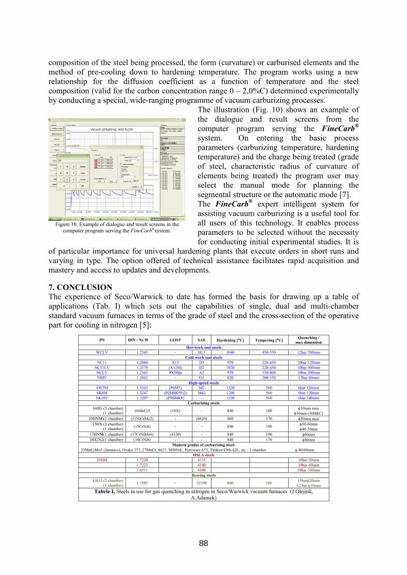
composition of the steel being processed, the form (curvature) or carburised elements and the method of pre-cooling down to hardening temperature. The program works using a new relationship for the diffusion coefficient as a function of temperature and the steel composition (valid for the carbon concentration range 0 – 2,0%C) determined experimentally by conducting a special, wide-ranging programme of vacuum carburizing processes.
The illustration (Fig. 10) shows an example of the dialogue and result screens from the computer program serving the FineCarb®
system. On entering the basic process parameters (carburizing temperature, hardening temperature) and the charge being treated (grade of steel, characteristic radius of curvature of elements being treated) the program user may select the manual mode for planning the segmental structure or the automatic mode [7]. The FineCarb® expert intelligent system for assisting vacuum carburizing is a useful tool for all users of this technology. It enables process parameters to be selected without the necessity for conducting initial experimental studies. It is
of particular importance for universal hardening plants that execute orders in short runs and varying in type. The option offered of technical assistance facilitates rapid acquisition and mastery and access to updates and developments. 7. CONCLUSION The experience of Seco/Warwick to date has formed the basis for drawing up a table of applications (Tab. I) which sets out the capabilities of single, dual and multi-chamber standard vacuum furnaces in terms of the grade of steel and the cross-section of the operative part for cooling in nitrogen [5]:
Figure 10. Example of dialogue and result screens in the computer program serving the FineCarb®system.
PN DIN / Nr.W GOST SAE Hardening [°C] Tempering [°C] Quenching / max dimension
Hot-work tool steels WCLV 1.2343 - H13 1040 450-550 12bar 700mm
Cold-work tool steels NC11 1.2080 X12 D3 970 220-450 10bar 120mm
NC11LV 1.2379 (X12M) D2 1020 220-450 10bar 500mm NCLV 1.2363 9X5Bju A2 970 150-400 10bar 300mm NMV 1.2842 - O2 820 200-350 12bar 80mm
High-speed steels SW7M 1.3343 (P6M5) M2 1220 560 6bar 120mm SK8M 1.3247 (P2M8K5Fi2) M42 1200 560 6bar 120mm SK10V 1.3207 (P9M4K8) - 1230 560 6bar 140mm
Carburizing steels 16HG (2 chamber)
(1 chamber) 16MnCr5 (18X) - 840 180 φ30mm max φ10mm (30HRC)
20HNM (2 chamber) (21NiCrMo2) - (8620) 860 170 φ30mm max 15HN (2 chamber)
(1 chamber) (15CrNi6) - - 840 190 φ50-60mm φ40-50mm
17HNM(1 chamber) (17CrNiMo6) (4320) - 840 190 φ60mm 18H2N2(1 chamber) (18CrNi8) - - 840 170 φ80mm
Modern grades of carburizing steel: 23MnCrMo5 (Jamasco), Ovake 277, 27MnCr, 8627, M50NiL, Pyroware 675, Timken CSS-42L, etc.- 1 chamber φ 40/60mm
HSLA steels 35HM 1.7220 4135 10bar-50mm
1.7223 4140 10bar-60mm 1.6511 4340 10bar-100mm
Bearing steels ŁH15 (2 chamber)
(1 chamber) 1.3505 - 52100 840 180 15barφ20mm 12 bar φ10mm
Tabele I. Steels in use for gas quenching in nitrogen in Seco/Warwick vacuum furnaces (J.Olejnik, A.Adamek)
88
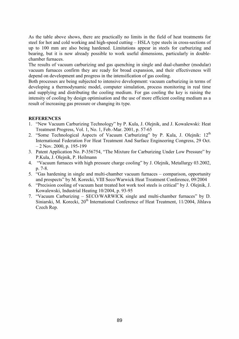
As the table above shows, there are practically no limits in the field of heat treatments for steel for hot and cold working and high-speed cutting – HSLA type steels in cross-sections of up to 100 mm are also being hardened. Limitations appear in steels for carburizing and bearing, but it is now already possible to work useful dimensions, particularly in double-chamber furnaces. The results of vacuum carburizing and gas quenching in single and dual-chamber (modular) vacuum furnaces confirm they are ready for broad expansion, and their effectiveness will depend on development and progress in the intensification of gas cooling. Both processes are being subjected to intensive development: vacuum carburizing in terms of developing a thermodynamic model, computer simulation, process monitoring in real time and supplying and distributing the cooling medium. For gas cooling the key is raising the intensity of cooling by design optimisation and the use of more efficient cooling medium as a result of increasing gas pressure or changing its type.
REFERENCES 1. “New Vacuum Carburizing Technology” by P. Kula, J. Olejnik, and J. Kowalewski: Heat
Treatment Progress, Vol. 1, No. 1, Feb.-Mar. 2001, p. 57-65 2. “Some Technological Aspects of Vacuum Carburizing” by P. Kula, J. Olejnik: 12th
International Federation For Heat Treatment And Surface Engineering Congress, 29 Oct. – 2 Nov. 2000, p. 195-199
3. Patent Application No. P-356754, “The Mixture for Carburizing Under Low Pressure” by P.Kula, J. Olejnik, P. Heilmann
4. “Vacuum furnaces with high pressure charge cooling” by J. Olejnik, Metallurgy 03.2002, p. 7-8.
5. “Gas hardening in single and multi-chamber vacuum furnaces – comparison, opportunity and prospects” by M. Korecki, VIII Seco/Warwick Heat Treatment Conference, 09/2004
6. “Precision cooling of vacuum heat treated hot work tool steels is critical” by J. Olejnik, J. Kowalewski, Industrial Heating 10/2004, p. 93-95
7. “Vacuum Carburizing – SECO/WARWICK single and multi-chamber furnaces” by D. Siniarski, M. Korecki, 20th International Conference of Heat Treatment, 11/2004, Jihlava Czech Rep.
89

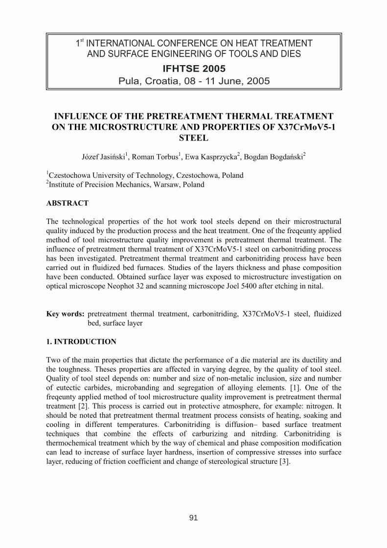
INFLUENCE OF THE PRETREATMENT THERMAL TREATMENT
ON THE MICROSTRUCTURE AND PROPERTIES OF X37CrMoV5-1
STEEL
Józef Jasiński1, Roman Torbus1, Ewa Kasprzycka2, Bogdan Bogdański2
1Czestochowa University of Technology, Czestochowa, Poland 2Institute of Precision Mechanics, Warsaw, Poland
ABSTRACT
The technological properties of the hot work tool steels depend on their microstructural quality induced by the production process and the heat treatment. One of the freqeunty appliedmethod of tool microstructure quality improvement is pretreatment thermal treatment. The influence of pretreatment thermal treatment of X37CrMoV5-1 steel on carbonitriding process has been investigated. Pretreatment thermal treatment and carbonitriding process have beencarried out in fluidized bed furnaces. Studies of the layers thickness and phase compositionhave been conducted. Obtained surface layer was exposed to microstructure investigation onoptical microscope Neophot 32 and scanning microscope Joel 5400 after etching in nital.
Key words: pretreatment thermal treatment, carbonitriding, X37CrMoV5-1 steel, fluidizedbed, surface layer
1. INTRODUCTION
Two of the main properties that dictate the performance of a die material are its ductility andthe toughness. Theses properties are affected in varying degree, by the quality of tool steel.Quality of tool steel depends on: number and size of non-metalic inclusion, size and number of eutectic carbides, microbanding and segregation of alloying elements. [1]. One of the freqeunty applied method of tool microstructure quality improvement is pretreatment thermal treatment [2]. This process is carried out in protective atmosphere, for example: nitrogen. It should be noted that pretreatment thermal treatment process consists of heating, soaking andcooling in different temperatures. Carbonitriding is diffusion– based surface treatment techniques that combine the effects of carburizing and nitrding. Carbonitriding is thermochemical treatment which by the way of chemical and phase composition modificationcan lead to increase of surface layer hardness, insertion of compressive stresses into surface layer, reducing of friction coefficient and change of stereological structure [3].
1 INTERNATIONAL CONFERENCE ON HEAT TREATMENT
AND SURFACE ENGINEERING OF TOOLS AND DIES
st
Pula, Croatia 08 - 11 June, 2005,
IFHTSE 2005
91
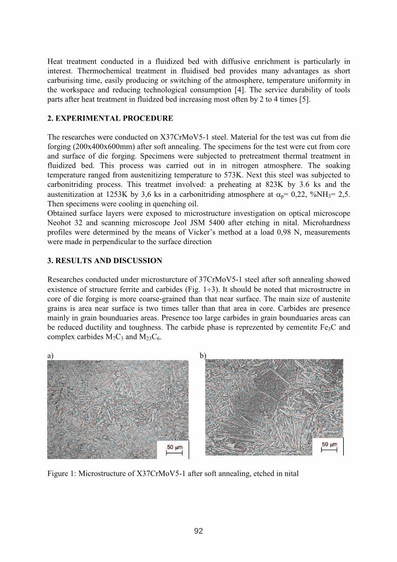
Heat treatment conducted in a fluidized bed with diffusive enrichment is particularly ininterest. Thermochemical treatment in fluidised bed provides many advantages as short carburising time, easily producing or switching of the atmosphere, temperature uniformity inthe workspace and reducing technological consumption [4]. The service durability of tools parts after heat treatment in fluidzed bed increasing most often by 2 to 4 times [5].
2. EXPERIMENTAL PROCEDURE
The researches were conducted on X37CrMoV5-1 steel. Material for the test was cut from die forging (200x400x600mm) after soft annealing. The specimens for the test were cut from core and surface of die forging. Specimens were subjected to pretreatment thermal treatment influidized bed. This process was carried out in in nitrogen atmosphere. The soaking temperature ranged from austenitizing temperature to 573K. Next this steel was subjected tocarbonitriding process. This treatmet involved: a preheating at 823K by 3.6 ks and the austenitization at 1253K by 3,6 ks in a carbonitriding atmosphere at αp= 0,22, %NH3= 2,5.Then specimens were cooling in quenching oil. Obtained surface layers were exposed to microstructure investigation on optical microscope Neohot 32 and scanning microscope Jeol JSM 5400 after etching in nital. Microhardness profiles were determined by the means of Vicker’s method at a load 0,98 N, measurements were made in perpendicular to the surface direction
3. RESULTS AND DISCUSSION
Researches conducted under microsturcture of 37CrMoV5-1 steel after soft annealing showedexistence of structure ferrite and carbides (Fig. 1÷3). It should be noted that microstructre incore of die forging is more coarse-grained than that near surface. The main size of austenite grains is area near surface is two times taller than that area in core. Carbides are presence mainly in grain bounduaries areas. Presence too large carbides in grain bounduaries areas canbe reduced ductility and toughness. The carbide phase is reprezented by cementite Fe3C and complex carbides M7C3 and M23C6.
a) b)
Figure 1: Microstructure of X37CrMoV5-1 after soft annealing, etched in nital
92
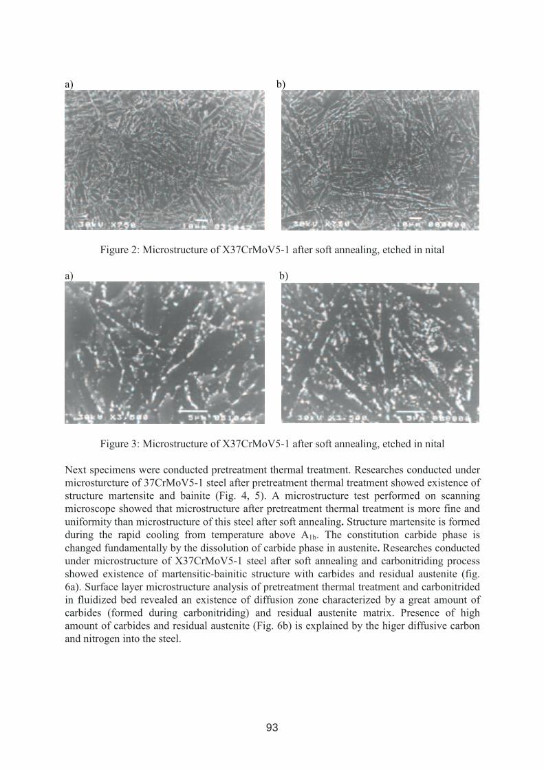
a) b)
Figure 2: Microstructure of X37CrMoV5-1 after soft annealing, etched in nital
a) b)
Figure 3: Microstructure of X37CrMoV5-1 after soft annealing, etched in nital
Next specimens were conducted pretreatment thermal treatment. Researches conducted under microsturcture of 37CrMoV5-1 steel after pretreatment thermal treatment showed existence of structure martensite and bainite (Fig. 4, 5). A microstructure test performed on scanning microscope showed that microstructure after pretreatment thermal treatment is more fine anduniformity than microstructure of this steel after soft annealing. Structure martensite is formedduring the rapid cooling from temperature above A1b. The constitution carbide phase is changed fundamentally by the dissolution of carbide phase in austenite. Researches conductedunder microstructure of X37CrMoV5-1 steel after soft annealing and carbonitriding process showed existence of martensitic-bainitic structure with carbides and residual austenite (fig.6a). Surface layer microstructure analysis of pretreatment thermal treatment and carbonitrided in fluidized bed revealed an existence of diffusion zone characterized by a great amount of carbides (formed during carbonitriding) and residual austenite matrix. Presence of highamount of carbides and residual austenite (Fig. 6b) is explained by the higer diffusive carbonand nitrogen into the steel.
93
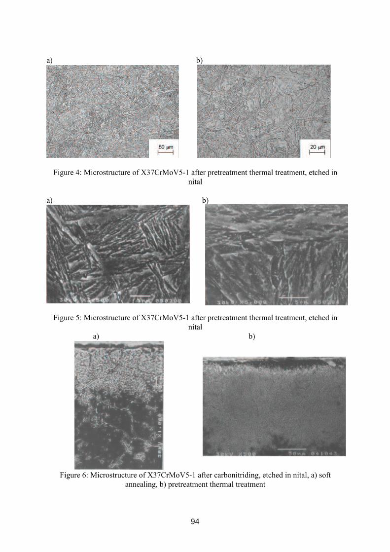
a) b)
Figure 4: Microstructure of X37CrMoV5-1 after pretreatment thermal treatment, etched in nital
a) b)
Figure 5: Microstructure of X37CrMoV5-1 after pretreatment thermal treatment, etched in nital
a) b)
Figure 6: Microstructure of X37CrMoV5-1 after carbonitriding, etched in nital, a) softannealing, b) pretreatment thermal treatment
94
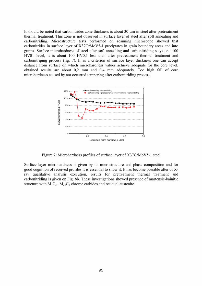
It should be noted that carbonitrides zone thickness is about 30 µm in steel after pretreatment thermal treatment. This zone is not observed in surface layer of steel after soft annealing andcarbonitriding. Microstructure tests performed on scanning microscope showed that carbonitrides in surface layer of X37CrMoV5-1 preciptates in grain boundary areas and into grains. Surface microhardness of steel after soft annealing and carbonitriding stays on 1100HV01 level, it is about 100 HV0,1 less than after pretreatment thermal treatment andcarbonitriging process (fig. 7). If as a criterion of surface layer thickness one can accept distance from surface on which microhardness values achieve adequate for the core level,obtained results are about 0,2 mm and 0,4 mm adequately. Too high fall of core microhardness caused by not occurred tempering after carbonitriding process.
0,2 0,4 0,6 0,8
0
200
400
600
800
1000
1200soft annealing + carbonitriding
soft annealing + pretreatment thermal treatment + carbonitriding
Mic
roh
ard
ness
HV
01
Distance from surface x, mm
Figure 7: Microhardness profiles of surface layer of X37CrMoV5-1 steel
Surface layer microhardness is given by its microstructure and phase composition and for good cognition of received profiles it is essential to show it. It has become possible after of X-ray qualitative analysis execution, results for pretreatment thermal treatment andcarbonitriding is given on Fig. 8b. These investigations showed presence of martensic-bainitic structure with M7C3 , M23C6 chrome carbides and residual austenite.
95
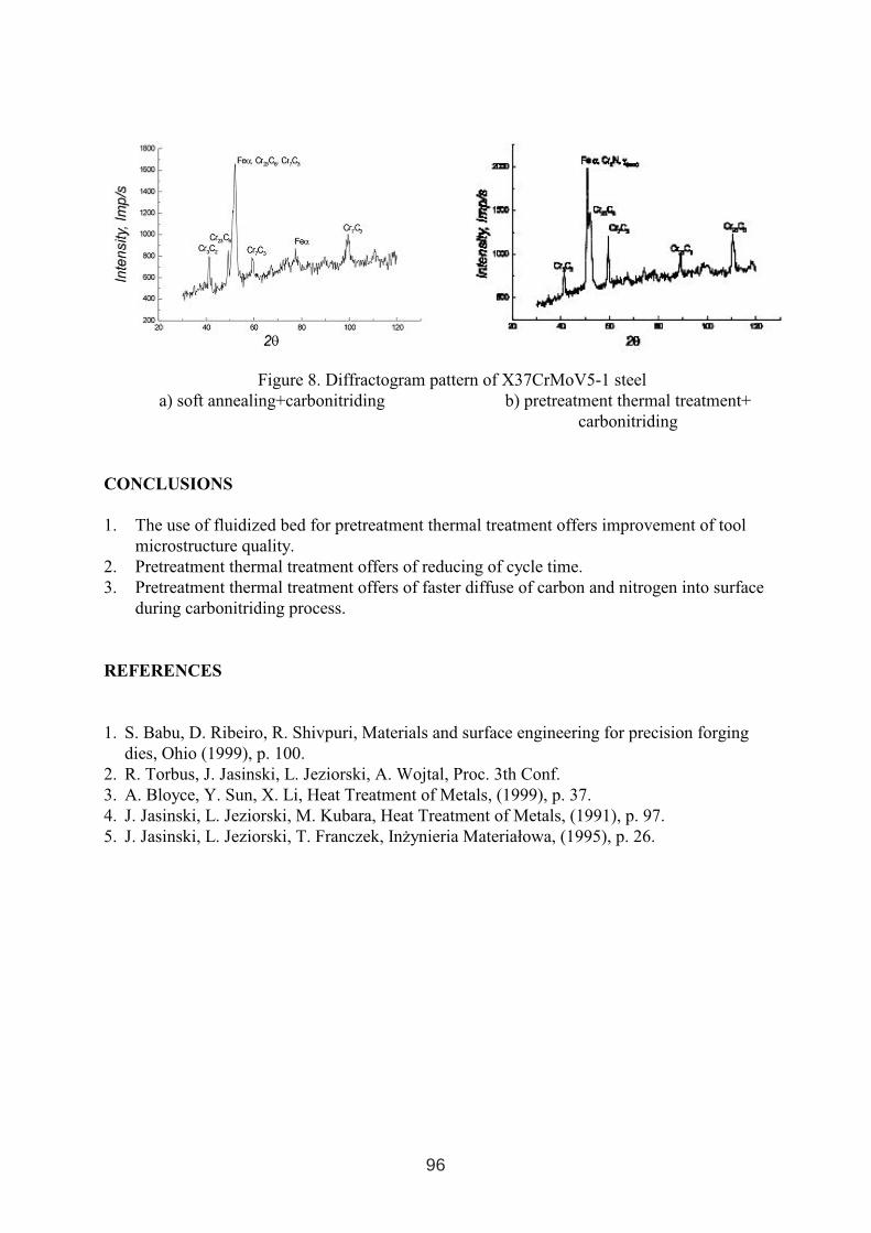
Figure 8. Diffractogram pattern of X37CrMoV5-1 steela) soft annealing+carbonitriding b) pretreatment thermal treatment+
carbonitriding
CONCLUSIONS
1. The use of fluidized bed for pretreatment thermal treatment offers improvement of tool microstructure quality.
2. Pretreatment thermal treatment offers of reducing of cycle time. 3. Pretreatment thermal treatment offers of faster diffuse of carbon and nitrogen into surface
during carbonitriding process.
REFERENCES
1. S. Babu, D. Ribeiro, R. Shivpuri, Materials and surface engineering for precision forgingdies, Ohio (1999), p. 100.
2. R. Torbus, J. Jasinski, L. Jeziorski, A. Wojtal, Proc. 3th Conf. 3. A. Bloyce, Y. Sun, X. Li, Heat Treatment of Metals, (1999), p. 37. 4. J. Jasinski, L. Jeziorski, M. Kubara, Heat Treatment of Metals, (1991), p. 97. 5. J. Jasinski, L. Jeziorski, T. Franczek, Inżynieria Materiałowa, (1995), p. 26.
96
INFLUENCE OF QUENCHING OILS COMPOSITION ON THECOOLING RATE
Ljiljana Pedišić1, Božidar Matijević2, Boris Perić1
1 MAZIVA-ZAGREB d.o.o., Radnička cesta 175, Zagreb 2 University of Zagreb, Faculty of Mechanical Engineering and Naval Architecture,
Ivana Lučića 5, Zagreb
ABSTRACT
Quenching media are applied on heat treatment processes of materials in order to achieve specific properties. By correct selection of adequate quenchant the risk of tensile stresses, and also of cracking and workpiece distortions, is decreased. Environment, human protection and safety requirements are the factors which directly influence the development of qenchants, i.e. the quenching medium composition. The composition of modern quenchants is becoming more and more sophisticated so that a great deal of usual components is replaced with new, less harmful substances. High-performance quench oils must have the following properties: oxidation and thermal resistance, elevated flash point, decreased volatility and acceptable heat-transfer characteristics. By changing the composition of quenching oils, base oils and additives, the cooling rate is also changed. The examination results of physical-chemical properties of new quenching oil compositions and also their cooling rates are presented in this paper.
Key words: hardening, cooling properties, quenching oils, additives
1. INTRODUCTION
There are numerous quenching media available for heat treatment processes. The ISO 6743 standard establishes a detailed classification of hardening media of the family U, for use in the field of heat treatment [1]. According to ISO 6743-14, Heat treatment-U, oils and similar products are sorted into 6 categories. Each category isdesignated by a symbol. The designated symbols are: H- mineral oil type products, A- water and polymer solutions, emulsions, S- molten salt, G- gas, F- products used in fluidised bed hardening, and K- indicates all other cases. The general classification of quenching media is based on the vapour blanket stage formation after the immersion of a hot workpiece, i.e. on the Leidenfrost phenomenon. The vapour blanket stage is formed by water (A), oil (H) and brine and polymers (A). This phenomenon does not occur with salts (S), fluidised bed hardening (F), and gas (G) . The cooling rates of different quenching media vary greatly.
1 INTERNATIONAL CONFERENCE ON HEAT TREATMENT
AND SURFACE ENGINEERING OF TOOLS AND DIES
st
Pula, Croatia 08 - 11 June, 2005,
IFHTSE 2005
97
2. PRINCIPLES OF COOLING
Upon the immersion of a hot workpiece into a quenching medium, which causes the formation of vapour blanket, the quenching process develops in three stages: vapour blanket stage, boiling stage and convection stage [2]. The vapour blanket stage is formed around the workpiece immediately when it is immersed into the medium if its temperature is high enough. This blanket acts as an insulator and is known as the Leidenfrost phenomenon. The vapour blanket has a low thermal conductivity coefficient and because of that the rate of cooling at this stage is slow. The duration of this stage depends first of all on the composition of the quenching medium. The boiling stage is developed by decreasing temperature. Vapour blanket stage becomes unstable and breaks down, allowing the medium to come into contact with the workpiece surface. The vapour blanket is also dependent on the cooling medium type and workpiece geometry. Boiling forms bubbles and decomposes the medium. Consequently, the cooler medium is continually coming into contact with the surface of the workpiece and heat is transferred very quickly. In this stage, maximum cooling is obtained and with the decreasing temperature, the boiling of the quenchant is decreased. The last stage of the cooling process is the contact stage. When the temperature of the workpiece decreases to a temperature below the boiling point of the medium, the heat is transferred by the natural convection of the quenching medium. In this stage the heat extraction takes place slowly but the cooling process can be accelerated by the medium agitation [3].
3. COMPOSITION AND PROPERTIES OF QUENCHING OILS
Quenching oils contain base oil and different types of additives according to application requirements [4]. Mineral oils, synthetic and also natural vegetable oils or oils of animal origin can be used as the base oil. Mineral base oils are widely used because of their advantages in stability in comparison to natural oils, or lower prices in comparison to synthetic oils. Mineral base oils are of naphtenic or paraffinic type with lowered quantity of aromatic compounds. Additives fulfil the following functions: oxidation inhibition, antifoaming, easier cleaning of the workpiece, increased cooling rates, etc. There are numerous compound possibilities but environmental and safety requirements have a strong influence on the additive selection. In this type of industrial oils an important restriction is placed on barium additives which have been in use for years and now they should be replaced [5]. High-performance quenching oil must have oxidation resistance and low sludge formation, must be non-staining and have an elevated flash point and acceptable heat-transfer characteristics. Quenching oils should be selected on the basis of their heat transfer characteristics. Typically, quenching oils are classified into three groups: fast - accelerated oils; medium speed - conventional oils; and marquenching - hot oils [6]. The selection of quenching oils is based on the material to be quenched and the heat treatment process. Table I presents the classification of oils for heat treatment according to ISO 6743-14 in accordance with specific application.
98
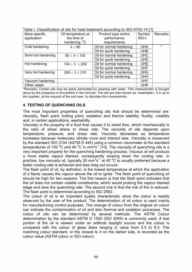
Table I. Classification of oils for heat treatment according to ISO 6743-14 [1] More specific application
Oil temperature at the time of
hardening, 0C
Product type and/or performance requirements
Symbol ISO-L
Remarks
Oil for normal hardening UHA Cold hardening ϑ ≤ 80 Oil for quick hardening UHB
Oil for normal hardening UHC Semi hot hardening 80 < ϑ ≤ 130 Oil for quick hardening UHD
Oil for normal hardening UHE Hot hardening 130 < ϑ ≤ 200 Oil for quick hardening UHF
Oil for normal hardening UHG Very hot hardening 200 < ϑ ≤ 310 Oil for quick hardening UHH
Vacuum hardening UHV
*
Other cases UHK *Remarks: Certain oils may be easily eliminated by washing with water. This characteristic is brought about by the presence of emulsifiers in the formula. The oils are then known as «washable». It is up to the supplier, at the request of the end user, to stipulate this characteristic.
4. TESTING OF QUENCHING OILS
The most important properties of quenching oils that should be determined are: viscosity, flash point, boiling point, oxidation and thermo stability, fluidity, volatilityand, in certain applications, washability. Viscosity is the property of a fluid that causes it to resist flow, which mechanically is the ratio of shear stress to shear rate. The viscosity of oils depends upon temperature, pressure, and shear rate. Viscosity decreases as temperature increases because molecules vibrate more and interact less. Viscosity is measured by the standard ISO 3104 (ASTM D 445) using a common viscometer at the standard temperatures of 100 0C and 40 0C in mm2s-1 [10]. The viscosity of quenching oils is a very important property for the quenching hardening process. Viscous oil will produce a more stable vapour blanket, consequently slowing down the cooling rate. In practice, low viscosity oil, typically 20 mm2s-1 at 40 0C is usually preferred because a faster cooling rate is achieved and less drag out occurs. The flash point of oil, by definition, is the lowest temperature at which the application of a flame causes the vapour above the oil to ignite. The flash point of quenching oil should be high for two reasons. The first reason is that the flash point indicates that the oil does not contain volatile constituents, which would prolong the vapour blanket stage and slow the quenching rate. The second one is that the risk of fire is reduced. The flash point is determined according to ISO 2592. The colour of oil is an important quality characteristic since the colour is readily observed by the user of the product. The determination of oil colour is used mainly for manufacturing control purposes. The change of colour from the original oil colour can indicate the contamination of oil and also thermal and oxidation processes. The colour of oils can be determined by several methods. The ASTM Colour determination by the standard ASTM D 1500 (ISO 2049) is commonly used. A test portion of the oil is viewed under an artificial daylight source and the colour iscompared with the colour of glass disks ranging in value from 0.5 to 8.0. The matching colour standard, or the closest to it on the darker side, is recorded as the colour value (ASTM colour or ISO colour).
99
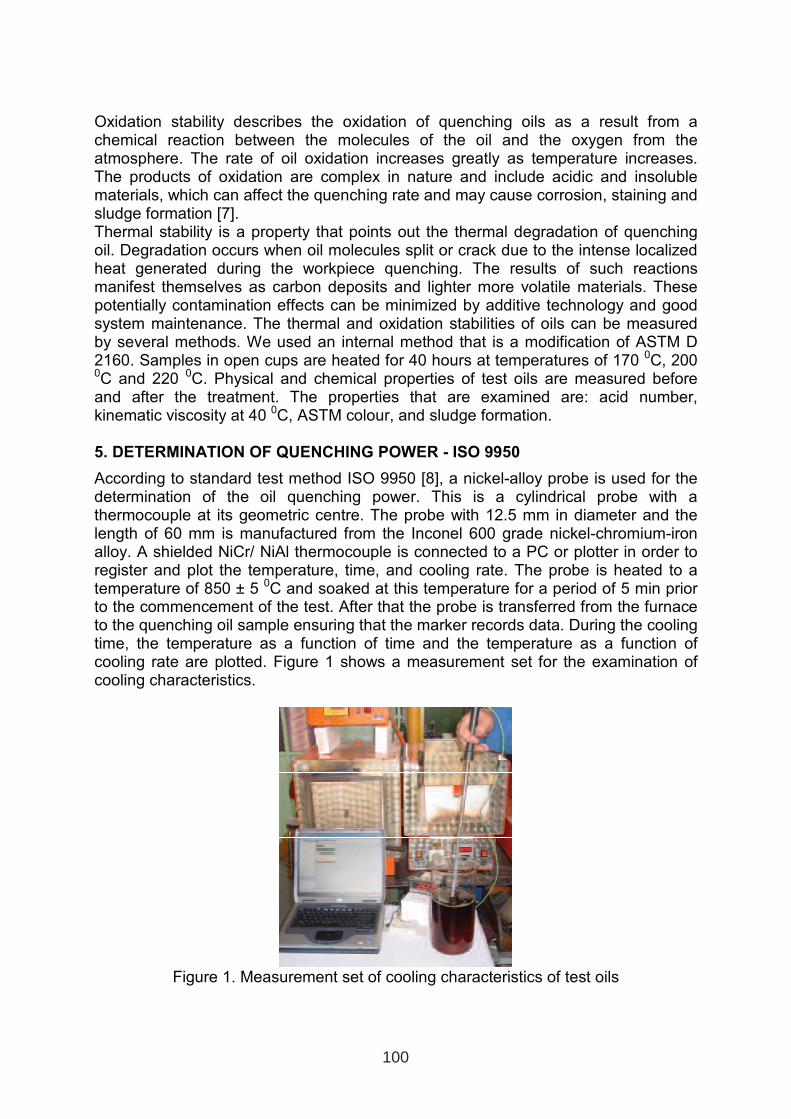
Oxidation stability describes the oxidation of quenching oils as a result from a chemical reaction between the molecules of the oil and the oxygen from the atmosphere. The rate of oil oxidation increases greatly as temperature increases. The products of oxidation are complex in nature and include acidic and insoluble materials, which can affect the quenching rate and may cause corrosion, staining and sludge formation [7]. Thermal stability is a property that points out the thermal degradation of quenching oil. Degradation occurs when oil molecules split or crack due to the intense localized heat generated during the workpiece quenching. The results of such reactions manifest themselves as carbon deposits and lighter more volatile materials. These potentially contamination effects can be minimized by additive technology and good system maintenance. The thermal and oxidation stabilities of oils can be measured by several methods. We used an internal method that is a modification of ASTM D 2160. Samples in open cups are heated for 40 hours at temperatures of 170 0C, 200 0C and 220 0C. Physical and chemical properties of test oils are measured before and after the treatment. The properties that are examined are: acid number, kinematic viscosity at 40 0C, ASTM colour, and sludge formation.
5. DETERMINATION OF QUENCHING POWER - ISO 9950
According to standard test method ISO 9950 [8], a nickel-alloy probe is used for the determination of the oil quenching power. This is a cylindrical probe with a thermocouple at its geometric centre. The probe with 12.5 mm in diameter and the length of 60 mm is manufactured from the Inconel 600 grade nickel-chromium-iron alloy. A shielded NiCr/ NiAl thermocouple is connected to a PC or plotter in order to register and plot the temperature, time, and cooling rate. The probe is heated to a temperature of 850 ± 5 0C and soaked at this temperature for a period of 5 min prior to the commencement of the test. After that the probe is transferred from the furnace to the quenching oil sample ensuring that the marker records data. During the cooling time, the temperature as a function of time and the temperature as a function of cooling rate are plotted. Figure 1 shows a measurement set for the examination of cooling characteristics.
Figure 1. Measurement set of cooling characteristics of test oils
100
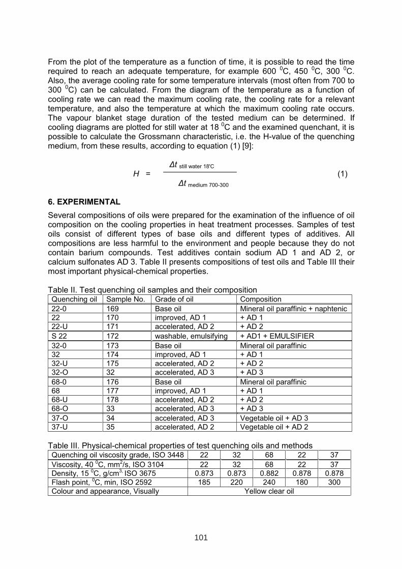
From the plot of the temperature as a function of time, it is possible to read the time required to reach an adequate temperature, for example 600 0C, 450 0C, 300 0C. Also, the average cooling rate for some temperature intervals (most often from 700 to 300 0C) can be calculated. From the diagram of the temperature as a function of cooling rate we can read the maximum cooling rate, the cooling rate for a relevant temperature, and also the temperature at which the maximum cooling rate occurs. The vapour blanket stage duration of the tested medium can be determined. If cooling diagrams are plotted for still water at 18 0C and the examined quenchant, it ispossible to calculate the Grossmann characteristic, i.e. the H-value of the quenching medium, from these results, according to equation (1) [9]:
∆t still water 18'C
H = (1) ∆t medium 700-300
6. EXPERIMENTAL
Several compositions of oils were prepared for the examination of the influence of oil composition on the cooling properties in heat treatment processes. Samples of test oils consist of different types of base oils and different types of additives. All compositions are less harmful to the environment and people because they do not contain barium compounds. Test additives contain sodium AD 1 and AD 2, or calcium sulfonates AD 3. Table II presents compositions of test oils and Table III their most important physical-chemical properties.
Table II. Test quenching oil samples and their composition Quenching oil Sample No. Grade of oil Composition
22-0 169 Base oil Mineral oil paraffinic + naphtenic
22 170 improved, AD 1 + AD 1
22-U 171 accelerated, AD 2 + AD 2
S 22 172 washable, emulsifying + AD1 + EMULSIFIER
32-0 173 Base oil Mineral oil paraffinic
32 174 improved, AD 1 + AD 1
32-U 175 accelerated, AD 2 + AD 2
32-O 32 accelerated, AD 3 + AD 3
68-0 176 Base oil Mineral oil paraffinic
68 177 improved, AD 1 + AD 1
68-U 178 accelerated, AD 2 + AD 2
68-O 33 accelerated, AD 3 + AD 3
37-O 34 accelerated, AD 3 Vegetable oil + AD 3
37-U 35 accelerated, AD 2 Vegetable oil + AD 2
Table III. Physical-chemical properties of test quenching oils and methodsQuenching oil viscosity grade, ISO 3448 22 32 68 22 37
Viscosity, 40 0C, mm2/s, ISO 3104 22 32 68 22 37
Density, 15 0C, g/cm3, ISO 3675 0.873 0.873 0.882 0.878 0.878
Flash point, 0C, min, ISO 2592 185 220 240 180 300
Colour and appearance, Visually Yellow clear oil
101
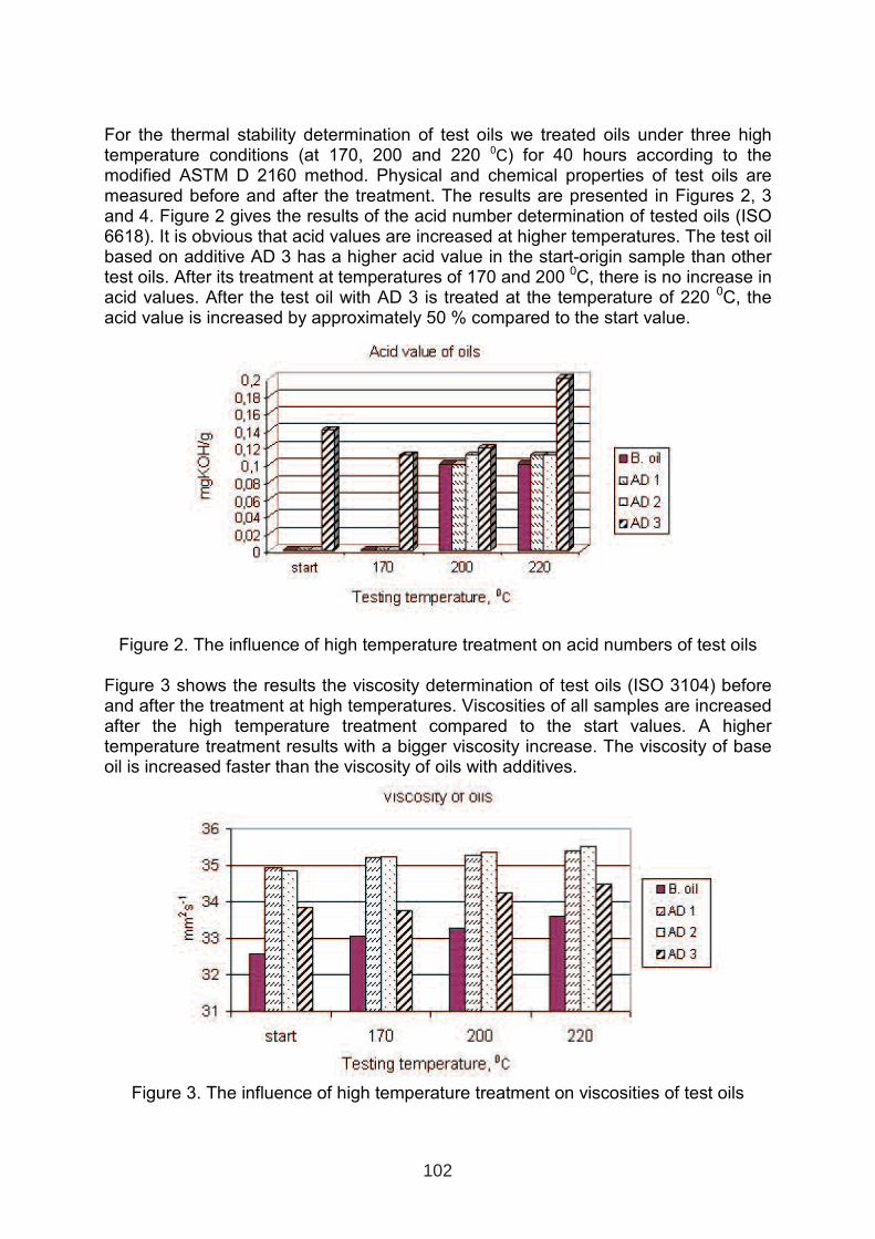
For the thermal stability determination of test oils we treated oils under three high temperature conditions (at 170, 200 and 220 0C) for 40 hours according to the modified ASTM D 2160 method. Physical and chemical properties of test oils are measured before and after the treatment. The results are presented in Figures 2, 3 and 4. Figure 2 gives the results of the acid number determination of tested oils (ISO 6618). It is obvious that acid values are increased at higher temperatures. The test oil based on additive AD 3 has a higher acid value in the start-origin sample than other test oils. After its treatment at temperatures of 170 and 200 0C, there is no increase in acid values. After the test oil with AD 3 is treated at the temperature of 220 0C, the acid value is increased by approximately 50 % compared to the start value.
Figure 2. The influence of high temperature treatment on acid numbers of test oils
Figure 3 shows the results the viscosity determination of test oils (ISO 3104) before and after the treatment at high temperatures. Viscosities of all samples are increased after the high temperature treatment compared to the start values. A higher temperature treatment results with a bigger viscosity increase. The viscosity of base oil is increased faster than the viscosity of oils with additives.
Figure 3. The influence of high temperature treatment on viscosities of test oils
102
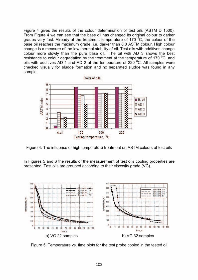
Figure 4 gives the results of the colour determination of test oils (ASTM D 1500). From Figure 4 we can see that the base oil has changed its original colour to darker grades very fast. Already at the treatment temperature of 170 0C, the colour of the base oil reaches the maximum grade, i.e. darker than 8.0 ASTM colour. High colour change is a measure of the low thermal stability of oil. Test oils with additives change colour more slowly than the pure base oil., The oil with AD 3 shows the best resistance to colour degradation by the treatment at the temperature of 170 0C, and oils with additives AD 1 and AD 2 at the temperature of 220 0C. All samples were checked visually for sludge formation and no separated sludge was found in any sample.
Figure 4. The influence of high temperature treatment on ASTM colours of test oils
In Figures 5 and 6 the results of the measurement of test oils cooling properties are presented. Test oils are grouped according to their viscosity grade (VG).
a) VG 22 samples b) VG 32 samples
Figure 5. Temperature vs. time plots for the test probe cooled in the tested oil
103
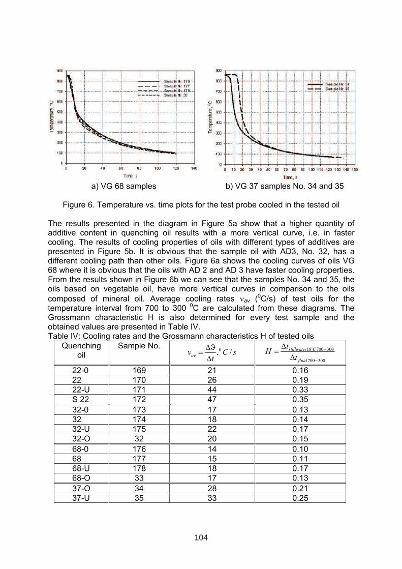
a) VG 68 samples b) VG 37 samples No. 34 and 35
Figure 6. Temperature vs. time plots for the test probe cooled in the tested oil
The results presented in the diagram in Figure 5a show that a higher quantity of additive content in quenching oil results with a more vertical curve, i.e. in faster cooling. The results of cooling properties of oils with different types of additives are presented in Figure 5b. It is obvious that the sample oil with AD3, No. 32, has a different cooling path than other oils. Figure 6a shows the cooling curves of oils VG 68 where it is obvious that the oils with AD 2 and AD 3 have faster cooling properties. From the results shown in Figure 6b we can see that the samples No. 34 and 35, the oils based on vegetable oil, have more vertical curves in comparison to the oils
composed of mineral oil. Average cooling rates νav (0C/s) of test oils for the temperature interval from 700 to 300 0C are calculated from these diagrams. The Grossmann characteristic H is also determined for every test sample and the obtained values are presented in Table IV. Table IV: Cooling rates and the Grossmann characteristics H of tested oils
Quenching oil
Sample No. sC
tv
av/,0
∆
∆ϑ=
300700
300700'18
−
−
∆
∆=
fluid
Cstillwater
t
tH
22-0 169 21 0.16
22 170 26 0.19
22-U 171 44 0.33
S 22 172 47 0.35
32-0 173 17 0.13
32 174 18 0.14
32-U 175 22 0.17
32-O 32 20 0.15
68-0 176 14 0.10
68 177 15 0.11
68-U 178 18 0.17
68-O 33 17 0.13
37-O 34 28 0.21
37-U 35 33 0.25
104
7. CONCLUSION
According to the latest environmental and safety requirements we have made quenching oils with an adequate composition so that are less harmful as they do not contain additives with barium which have been irreplaceable for years. We prepared several grades of test oils VG 22, 32 and 68 with different types of additives. In addition, we prepared the quenching oil of viscosity grade 37, based on vegetable oils, improved with additives. For all oil samples we determined cooling curves, average cooling rates and H-values by the ISO 9950 standard. From these examination results it is obvious that cooling characteristics are dependent on the composition of the oil. Cooling characteristics are changed by adding different types of additives. They also depend on the concentration of additives and the type of base oil. By adding additives, the cooling rate is increased as well as the H-value. Based on these results, specific oil compositions can be used in steel quenching processes in accordance with specific quality requirements of a workpiece.
8. LITERATURE
1. ISO 6743 – 14; Lubricants, industrial oils and related products (class L) – Classification- Part 14: Family U (Heat treatment), 1994.
2. Drayton PACS Quenchmaster Reports, www.dpacs.co.uk3. www.petrofer.com4. B. Matijević, Lj. Pedišić, B. Perić; The influence of additives on the cooling
properties of quenching oils (in Croatian), International conference of materialsand tribology MATRIB ‘04, June 23-24, 2004., Vela Luka, Croatia
5. M. Rocker; VKIS-VSI-Komponentenliste fϋr KSS nach DIN 51385, 13th
International Colloquium Tribology, Bartz, W. ISBN 3-924813-48-5, pp 749-754, TAE Jan.15-17, 2002., Ostfildern, Germany
6. D. S. MacKenzie; Selection of Quench Oils, Houghton International, Valley Forge PA
7. D. S. MacKenzie, L. Gunsalus, and I. Lazarev; Effects of Contamination on Quench-Oil Cooling Rate, Houghton International Inc., www.houghtonintl.com
8. ISO 9950, Industrial quenching oils - Determinations of cooling characteristics-Nickel-alloy probe test method, 1995.
9. B. Liščić, M. Stupnišek, F. Cajner, T. Filetin; Heat treatment (in Croatian), Praktikum FSB, Zagreb, 1991.
10. ASTM and ISO standards
105

THE INFLUENCE OF MULTIPLE SOLUTION ANNEALING ON KINETICS OF STRUCTURAL TRANSFORMATION
OF MARAGING STEELS
Ivica Kladarić; Dragomir Krumes; Radojka MarkovićUniversity of Osijek, Mechanical Engineering Faculty in Slavonski Brod, Trg I. B. Mažuranić 18, 35000 Slavonski Brod, Croatia
ABSTRACT
The paper presents effects of multiple solution annealing on kinetics of structural transformation of maraging steels 18 9 5. Multiple solution annealing testing was carried out in dilatometer by simultaneous registration of transformation temperatures austenite start As at heating and martensite start Ms at cooling and registration of linearly dilatatic changes. Analysis of dilatometric curves has quantified coefficients of dilatation during heating and coefficient of contraction during cooling, and has established mathematical model for determination of quantity of retained austenite in microstructure of maraging steels.
Key words: maraging steel, transformation temperatures, retained austenite
1. INTRODUCTION
Study of structural transformation kinetics of maraging steel during the thermal treatment has the purpose to determine the conditions for development of microstructures for assessment of their impact on properties of the steel. Current dilatometric studies of solution annealing have given evidence that maraging steel does not fulfill the rule of interdependence of Ms for temperature and duration of austenitic precipitation, which is the case with carbon and alloyed steels. The impact of Co in maraging has rarely been mentioned, although it is well known that: - Co is closely related to nickel and that this element, among other things, exerts
influence which in a sense stabilizes austenite and Ni (γ alloying elements), - That Co (besides Al) affects also steels with measurable (more notable) share of
carbon, so as to increase Ms, as opposed to all other elements, which decrease this temperature,
- That Co in all its different effects in alloyed steels “postpones” the agglomeration of carbide particle, therefore increasing steel resistance to deterioration.
These observations have led to introduction of special study of Co impact under condition of prolonged duration of exposure (“activation” through multiple solution annealing) in maraging.
1 INTERNATIONAL CONFERENCE ON HEAT TREATMENT
AND SURFACE ENGINEERING OF TOOLS AND DIES
st
Pula, Croatia 08 - 11 June, 2005,
IFHTSE 2005
107
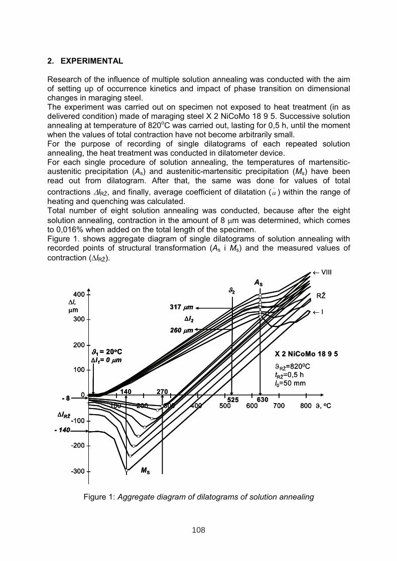
2. EXPERIMENTAL
Research of the influence of multiple solution annealing was conducted with the aim of setting up of occurrence kinetics and impact of phase transition on dimensional changes in maraging steel. The experiment was carried out on specimen not exposed to heat treatment (in as delivered condition) made of maraging steel X 2 NiCoMo 18 9 5. Successive solution annealing at temperature of 820oC was carried out, lasting for 0,5 h, until the moment when the values of total contraction have not become arbitrarily small. For the purpose of recording of single dilatograms of each repeated solution annealing, the heat treatment was conducted in dilatometer device. For each single procedure of solution annealing, the temperatures of martensitic-austenitic precipitation (As) and austenitic-martensitic precipitation (Ms) have been read out from dilatogram. After that, the same was done for values of total
contractions ∆lRŽ, and finally, average coefficient of dilatation (−
α ) within the range of heating and quenching was calculated. Total number of eight solution annealing was conducted, because after the eight
solution annealing, contraction in the amount of 8 µm was determined, which comes to 0,016% when added on the total length of the specimen. Figure 1. shows aggregate diagram of single dilatograms of solution annealing with recorded points of structural transformation (As i Ms) and the measured values of
contraction (∆lRŽ).
Figure 1: Aggregate diagram of dilatograms of solution annealing
I I I I I I I I
100 200 300 400 500 600 700 800 ϑ, oC
400 –
300 –
200 –
100 –
0 –
-100 –
-200 –
-300 –
∆l,
µm
- 8
∆∆lRŽ
- 140
AS
630
X 2 NiCoMo 18 9 5
ϑRŽ=8200C
tRŽ=0,5 h
l0=50 mm
MS
140 270
525
ϑϑ2
317 µµm
∆∆l2
260 µµm
ϑϑ1 = 20oC∆∆l1= 0 µµm
← VIII
RŽ
← I
I I I I I I I I
100 200 300 400 500 600 700 800 ϑ, oC
400 –
300 –
200 –
100 –
0 –
-100 –
-200 –
-300 –
∆l,
µm
I I I I I I I I
100 200 300 400 500 600 700 800 ϑ, oC
400 –
300 –
200 –
100 –
0 –
-100 –
-200 –
-300 –
∆l,
µm
- 8
∆∆lRŽ
- 140
- 8
∆∆lRŽ
- 140
AS
630
X 2 NiCoMo 18 9 5
ϑRŽ=8200C
tRŽ=0,5 h
l0=50 mm
MS
140 270
525
ϑϑ2
317 µµm
∆∆l2
260 µµm
ϑϑ1 = 20oC∆∆l1= 0 µµm
525
ϑϑ2
317 µµm
∆∆l2
260 µµm
ϑϑ1 = 20oC∆∆l1= 0 µµm
← VIII
RŽ
← I
108
Table I. gives readings of structural precipitation temperatures (As i Ms), contraction
measurements (∆lRŽ), calculated average coefficient of dilatation during heating
(betweenϑ1=20 oC and ϑ2 =525 oC) and contraction values during quenching
(between ϑ3=300 oC and ϑ4 =700 o C). The average dilatation coefficient (contraction coefficient) has been calculated according to the equation (1).
122
1221
1
)(
)()(),(
TTTD
TDTDTT
P
PP
−⋅
−=
−
α (1)
Where: α ( T1 , T2 ) - average coefficient of dilatation for temperature range between T1 and T2 ( T1 < T2 ), K-1
DP ( T1 ) - specimen length at temperature T1, mm DP ( T2 ) - specimen length at temperature T2, mm T1 , T2 - specimen temperature, K
Table I. Calculated amount average coefficient of dilatation
Ordinal solution annealing at ϑϑRŽ=820oC/0,5h reading and calculated
amount I II III IV V VI VII VIII
As,oC 630 630 630 630 630 630 630 630
Ms,oC 140 150 165 190 215 240 255 270
∆∆lRŽ, µm -140 -78 -44 -32 -18 -17 -15 -8
lo, mm 50 49,860 49,782 49,738 49,706 49,688 49,671 49,656
∆∆l2,µm (ϑ2=525oC) 260 278 293 300 305 310 315 315 −
α (20, 525) x10-6, K-1 10,297 11,041 11,655 11,944 12,151 12,354 12,558 12,562
∆∆l3,µm (ϑ3=300oC) -155 - - - -55 - - -
∆∆l4,µm (ϑ4=700oC) 225 - - - 323 - - - −
α (300, 700) x10-6 K-1 18,941 - - - 18,978 - - -
2.1. Assessment of results of multiple solution annealing
The analyses of results presented in Table I. show that repetition of the solution annealing of maraging steel X 2 NiCoMo 18 9 5: - does not result in change of temperature of martensitic–austenitic transformation As
(≈ 630 oC), - temperature of austenitic–martensitic transformation Ms increases (from 140 to
270 oC ),
- amounts of total contraction ∆lRŽ decrease (-140 up to -8 µm), - average dilatation coefficient (heating) increases (from 10,3x10⁻⁶ to 12,56x10⁻⁶ K-1), - average contraction coefficient (quenching) does not change (≈18,96x10⁻⁶ K-1). Persistence of the average contraction coefficient during quenching (≈18,96 x10⁻⁶ K-
1) indicates that during each solution annealing, within the range being considered, there must be the same combination of structural phases. Variability of the average dilatation coefficient at heating (from 10,3x10⁻⁶ to 12,56x10⁻⁶ K-1) indicates that each recurrent solution annealing results in change of the share of phase in initial structure. The growth of average coefficient during heating is most probably caused byincrease of the share of that phase which has the bigger average dilatation
109
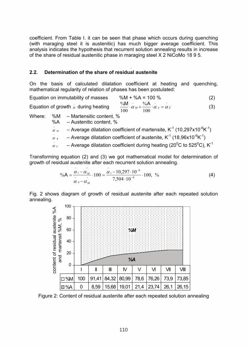
coefficient. From Table I. it can be seen that phase which occurs during quenching (with maraging steel it is austenitic) has much bigger average coefficient. This analysis indicates the hypothesis that recurrent solution annealing results in increase of the share of residual austenitic phase in maraging steel X 2 NiCoMo 18 9 5.
.2.2. Determination of the share of residual austenite
On the basis of calculated dilatation coefficient at heating and quenching, mathematical regularity of relation of phases has been postulated:
Equation on immutability of masses %M + %A = 100 % (2)
Equation of growth −
α during heating ZAM
−−−
=⋅+⋅ ααα100
%
100
% AM(3)
Where: %M – Martensitic content, % %A – Austenitic content, %
M
−
α – Average dilatation coefficient of martensite, K-1 (10,297x10-6K-1)
A
−
α – Average dilatation coefficient of austenite, K-1 (18,96x10⁻⁶K-1)
Z
−
α – Average dilatation coefficient during heating (200C to 5250C), K-1
Transforming equation (2) and (3) we got mathematical model for determination of growth of residual austenite after each recurrent solution annealing.
%,10010504,7
10297,10100%
6
6
⋅⋅
⋅−=⋅
−
−=
−
−−
−−
−−
z
MA
Mz α
αα
ααA (4)
Fig. 2 shows diagram of growth of residual austenite after each repeated solution annealing.
%A
%M
0
20
40
60
80
100
%M 100 91,41 84,32 80,99 78,6 76,26 73,9 73,85
%A 0 8,59 15,68 19,01 21,4 23,74 26,1 26,15
I II III IV V VI VII VIII
Figure 2: Content of residual austenite after each repeated solution annealing
co
nte
nt
ofre
sid
ualauste
nite
%A
and
mart
ensit
%M
,%
110
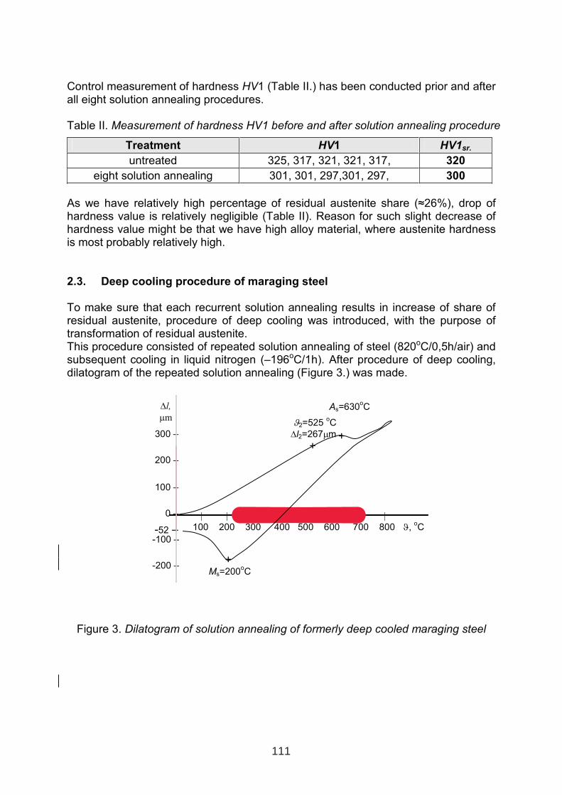
Control measurement of hardness HV1 (Table II.) has been conducted prior and after all eight solution annealing procedures.
Table II. Measurement of hardness HV1 before and after solution annealing procedure
Treatment HV1 HV1sr.
untreated 325, 317, 321, 321, 317, 320
eight solution annealing 301, 301, 297,301, 297, 300
As we have relatively high percentage of residual austenite share (≈26%), drop of hardness value is relatively negligible (Table II). Reason for such slight decrease of hardness value might be that we have high alloy material, where austenite hardness is most probably relatively high.
2.3. Deep cooling procedure of maraging steel
To make sure that each recurrent solution annealing results in increase of share of residual austenite, procedure of deep cooling was introduced, with the purpose of transformation of residual austenite. This procedure consisted of repeated solution annealing of steel (820oC/0,5h/air) and subsequent cooling in liquid nitrogen (–196oC/1h). After procedure of deep cooling, dilatogram of the repeated solution annealing (Figure 3.) was made.
Figure 3. Dilatogram of solution annealing of formerly deep cooled maraging steel
300 –
200 –
100 –
0 –
-100 –
-200 –
∆l,
µm
,.| , | | | | . | . | | .
100 200 300 400 500 600 700 800 ϑ,oC
As=630oC
+
+Ms=200
oC
-52 –
ϑ2=525 oC
∆l2=267µm
+
111
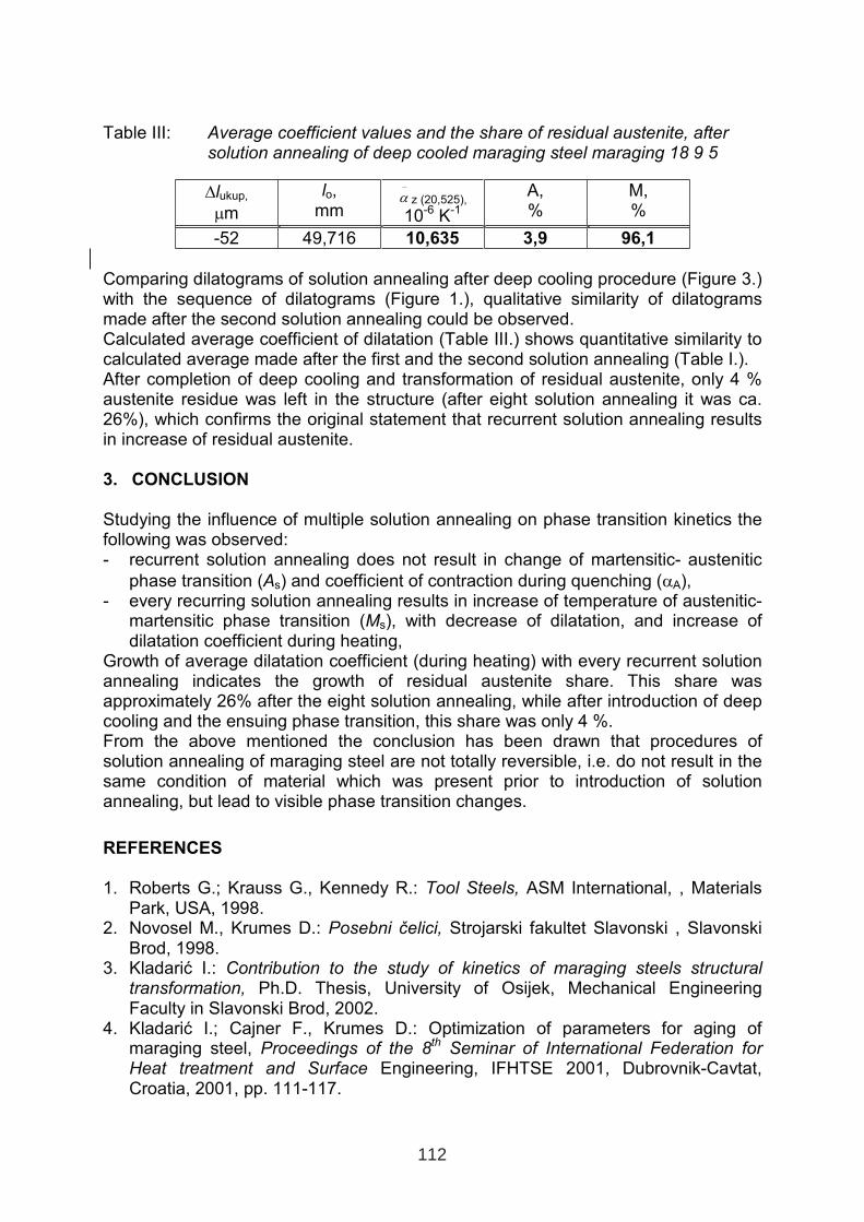
Table III: Average coefficient values and the share of residual austenite, after solution annealing of deep cooled maraging steel maraging 18 9 5
∆lukup,
µm
lo,mm
−
α z (20,525),
10-6 K-1
A, %
M, %
-52 49,716 10,635 3,9 96,1
Comparing dilatograms of solution annealing after deep cooling procedure (Figure 3.) with the sequence of dilatograms (Figure 1.), qualitative similarity of dilatograms made after the second solution annealing could be observed. Calculated average coefficient of dilatation (Table III.) shows quantitative similarity to calculated average made after the first and the second solution annealing (Table I.). After completion of deep cooling and transformation of residual austenite, only 4 % austenite residue was left in the structure (after eight solution annealing it was ca. 26%), which confirms the original statement that recurrent solution annealing resultsin increase of residual austenite.
3. CONCLUSION
Studying the influence of multiple solution annealing on phase transition kinetics the following was observed: - recurrent solution annealing does not result in change of martensitic- austenitic
phase transition (As) and coefficient of contraction during quenching (αA), - every recurring solution annealing results in increase of temperature of austenitic-
martensitic phase transition (Ms), with decrease of dilatation, and increase of dilatation coefficient during heating,
Growth of average dilatation coefficient (during heating) with every recurrent solution annealing indicates the growth of residual austenite share. This share was approximately 26% after the eight solution annealing, while after introduction of deep cooling and the ensuing phase transition, this share was only 4 %. From the above mentioned the conclusion has been drawn that procedures of solution annealing of maraging steel are not totally reversible, i.e. do not result in the same condition of material which was present prior to introduction of solution annealing, but lead to visible phase transition changes.
REFERENCES
1. Roberts G.; Krauss G., Kennedy R.: Tool Steels, ASM International, , MaterialsPark, USA, 1998.
2. Novosel M., Krumes D.: Posebni čelici, Strojarski fakultet Slavonski , Slavonski Brod, 1998.
3. Kladarić I.: Contribution to the study of kinetics of maraging steels structural transformation, Ph.D. Thesis, University of Osijek, Mechanical Engineering Faculty in Slavonski Brod, 2002.
4. Kladarić I.; Cajner F., Krumes D.: Optimization of parameters for aging of maraging steel, Proceedings of the 8th Seminar of International Federation for Heat treatment and Surface Engineering, IFHTSE 2001, Dubrovnik-Cavtat, Croatia, 2001, pp. 111-117.
112