Embed Size (px)
DESCRIPTION
The main objective of the project is to expand the market for energy efficient street lighting. The partners within the consortium are all convinced about the prosperous future for this technology, its significant energy saving potential (40 to 70 % energy reduction), environmental and economical benefits and the increased level of traffic safety for the public. EkoLum Smart Street Lighting plattform : www.ekolum.net
Citation preview
- 1 –
E-Street Work Package 5.4 28-08-2008
E-street Initiative
Work Package 5.4
Comprehensive report
This report will summarize the three previous reports within the WP 5. On behalf of the E-Street project (www.e-streetlight.com)
And supported by:
The sole responsibility for the content of this publication lies with the authors. It does not necessarily reflect the opinion of the European Communities. The European Commission is not responsible for any use that may be made of the information contained therein.
This text is developed by
- 2 –
E-Street Work Package 5.4 28-08-2008
Table of Contents 1. SUMMARY ....................................................................................................3
1.1 D5.4 - Comprehensive WP report summary ................................................................... 3 1.2 Summary slides Users guide .......................................................................................... 3 1.3 Summary Slides Adm tool ............................................................................................. 8
2 WORKING TOOL FOR MARKET PLAYERS .............................................12 2.1 Huge savings potential ................................................................................................. 12 2.2 Huge saving potentials utilizing new technology.......................................................... 12 2.3 Organizing outdoor lighting ......................................................................................... 13
3 TOPOLOGY OF ADMINISTRATIVE SYSTEMS.........................................14 3.1 Topology of streetlighting ........................................................................................... 14 3.2 Communication............................................................................................................ 15 3.3 System integrations of databases .................................................................................. 18
3.3.1 Database and data collection ................................................................................ 18 3.3.2 Combining data and experience............................................................................ 19 3.3.3 Sharing the data.................................................................................................... 19
3.4 Intelligent streetligting – at what level ? ....................................................................... 19 3.4.1 Switch cabinet...................................................................................................... 20 3.4.2 Luminaire............................................................................................................. 20 3.4.3 Switch cabinet and Luminaire .............................................................................. 21
4 ADMINISTRATIVE ASPECTS AND CHALLENGES ..................................22 4.1 Operation and maintenance .......................................................................................... 22 4.2 Energy metering and monitoring .................................................................................. 22 4.3 Human/machine interface ............................................................................................ 23 4.4 Principal description .................................................................................................... 23 4.5 Administration system for street lights ......................................................................... 24
4.5.1 Task list ............................................................................................................... 24 4.5.2 History ................................................................................................................. 25 4.5.3 Reporting ............................................................................................................. 25 4.5.4 Administration database for streetlight ................................................................. 25
4.6 Customer service application ....................................................................................... 25 4.7 Data collection from street light ................................................................................... 26
5 UPGRADING INSTALLATIONS .................................................................28 5.1 Upgrading of outdated installations .............................................................................. 28 5.2 Adaptive lighting ......................................................................................................... 28 5.3 Purchase - an important function.................................................................................. 29
6 LIGHTING CALCULATIONS ......................................................................31 7 MARKET DEVELOPMENT:........................................................................35
The E-street partners have been active in promoting the various prospects of Intelligent lighting. This is illustrated by the below table over several events where the partners have contributed. ............................................................................................... 37
- 3 –
E-Street Work Package 5.4 28-08-2008
1. SUMMARY
1.1 D5.4 - Comprehensive WP report summary The comprehensive report tries to summarize all the tasks covered by the WP5. A short PPT presentation summarizes the User guide for upgrading of old installations. The administrative challenges are discussed in chapter 4 in detail. In chapter 5, the presentations fro E-Street Forum meetings are introduced.
1.2 Summary slides Users guide
1
Upgrading of streetlight installations Users guide
Tor MjøsNorconsult AS
2
Index
�Huge savings potetials
�Organizing outdoornlighting
�How to get started?
�Adaptive lighting
�Purchase - an important function
�Lighting calculations
�Support schemes

- 4 –
E-Street Work Package 5.4 28-08-2008
3
European Market
� Overall saving potential 38 TWh/Year
�Replacing old installations reduction 37 %
�Dimming and regulating another 45 %
�Total effect: 66 %
� Oslo case (savings before “active dimming”)
�117 units (2003) - Pilot project (67 % savings)
�2.000 units (2004) - Full scale test project (62 %)
�4.000 units (2005/6) - Full scale project (52%)
4
Huge savings potential
� 50-70 % savings
� Symbolic value
� Dimming
� Environmental aspects
� Safety
� Prevention of crime
� Public services
� Utilize free electricity market
� Improved maintenance level
5
Huge savings potential
� Technology available
� Increased performance of the luminaries
� Dimming High pressure Sodium and White light
(yellow light + CDM)
� Short pay-back times
� LCC- calculations
� Adm. matters

- 5 –
E-Street Work Package 5.4 28-08-2008
6
Organizing outdoor lighting
� Establish local guidelines
�National standards
�Quality standards
�Level of light (lux, candela/m2)
�Avoid light pollution
�On/Off and dimming strategies
�Energy metering
�Communication
�Electricity tariffs
7
How to get started
� Road complexity
� Traffic volume
� Road construction
� Accident rates (if available?)
� Existing columns
� Today’s running costs?
� LCC - Life cycle calculation
� EN 13201
� CIE 115 Recommendations for streetlighting
8
Upgrading installations
� Reduction of running costs
� Initially save lamp shift
�Less maintenance
� Less electricity losses/ increased capacity on existing grid
� Increase performance
� Digital communication
- 6 –
E-Street Work Package 5.4 28-08-2008
9
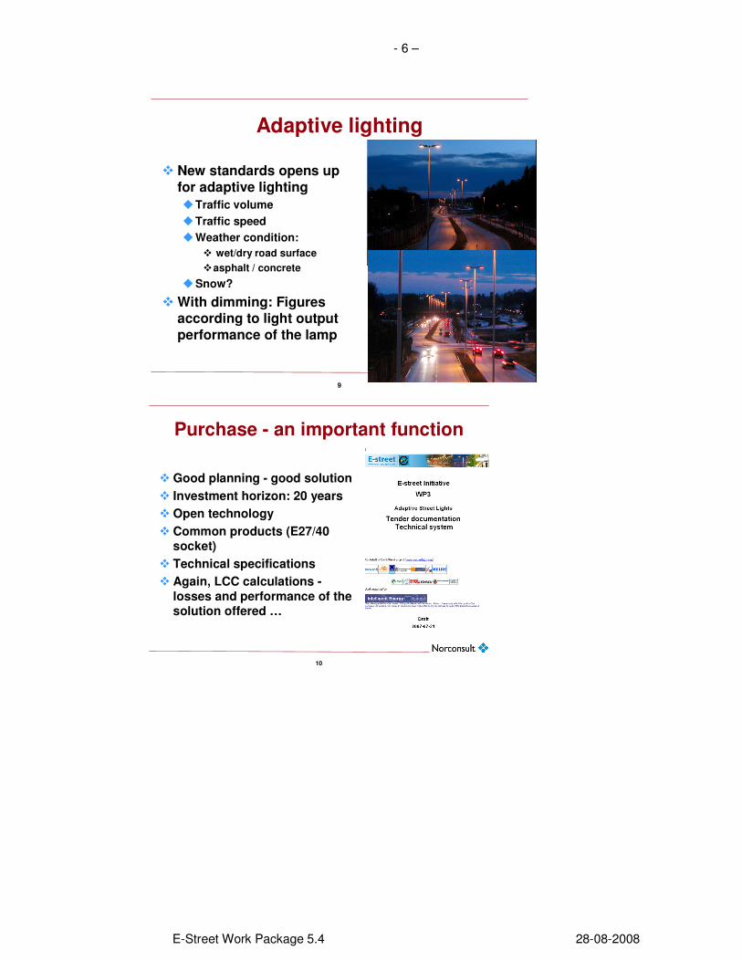
Adaptive lighting
� New standards opens up for adaptive lighting
�Traffic volume
�Traffic speed
�Weather condition:
� wet/dry road surface
�asphalt / concrete
�Snow?
� With dimming: Figures according to light output performance of the lamp
10
Purchase - an important function
� Good planning - good solution
� Investment horizon: 20 years
� Open technology
� Common products (E27/40 socket)
� Technical specifications
� Again, LCC calculations -
losses and performance of the solution offered …
- 7 –
E-Street Work Package 5.4 28-08-2008
11
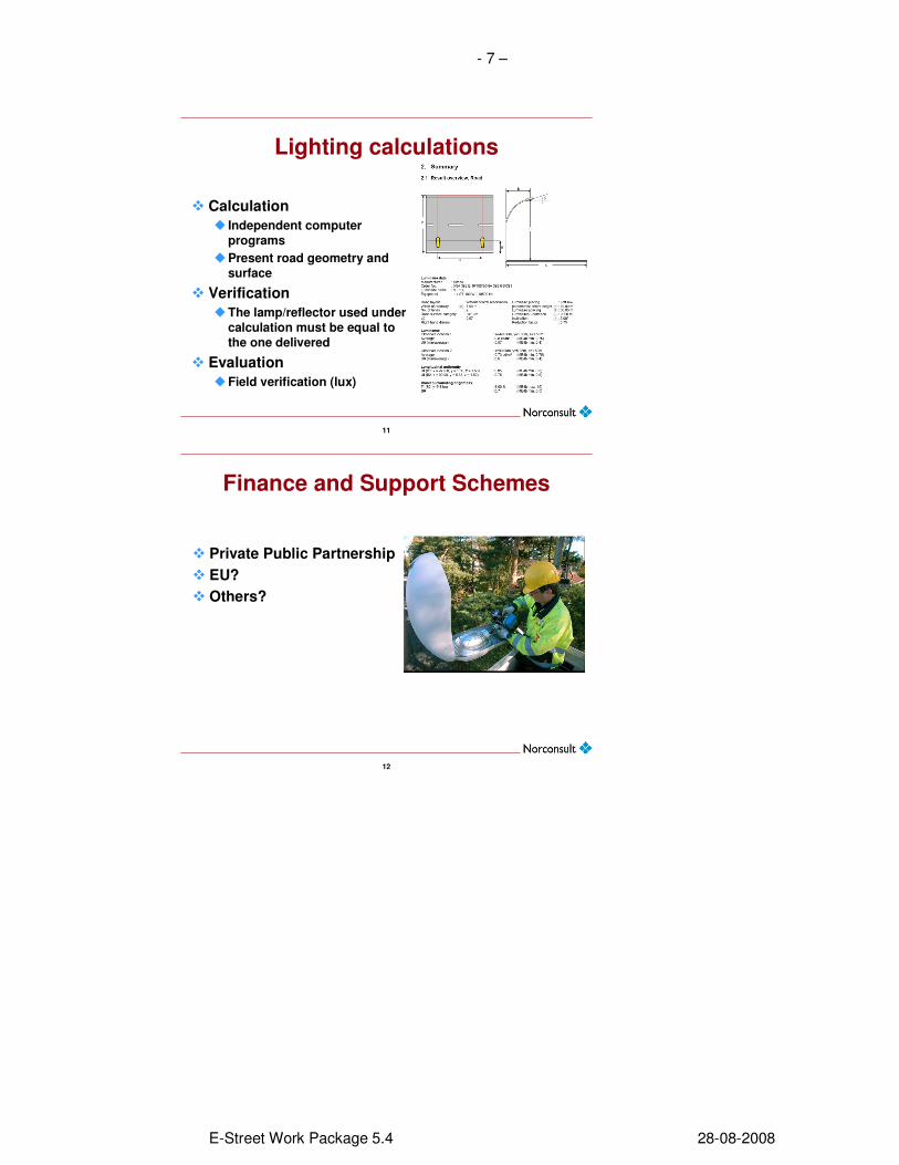
Lighting calculations
� Calculation
� Independent computer
programs
�Present road geometry and
surface
� Verification
�The lamp/reflector used under
calculation must be equal to
the one delivered
� Evaluation
�Field verification (lux)
12
Finance and Support Schemes
� Private Public Partnership
� EU?
� Others?

- 8 –
E-Street Work Package 5.4 28-08-2008
1.3 Summary Slides Adm tool The following slides presents the Administrative handling tool designed during the E-street project period.
| 3 |
Why an administration system ?
• Operators demands
– Costs distribution to different street owners
– Monitoring the contractors
– Information regarding safety
– Control and planning of maintenance
– Budget control
• Public services
– Web access to reporting errors
– Information about service levels
– Accurate geographical report
• Contractors
– Effective planning, reporting and billing
| 4 |
Powel StreetLight
Customercenter
Contractor
Street owner
Operator
Lamps
Powel StreetLight - Actors
Streetlighting administrasjon system at Hafslund
- 9 –
E-Street Work Package 5.4 28-08-2008
| 5 |
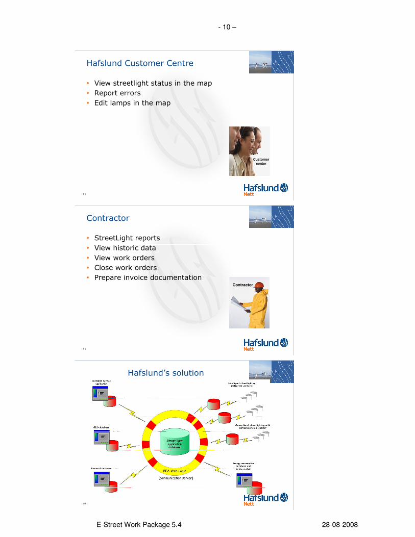
Street owner
• Street Light reports
• View historic data
• Work order reports
| 6 |
The public
• View Streetlight status in the map
• Report errors
| 7 |
Operator
• Fast maintenance processes– Error reported from the public or the lamps
– Automatically generation of work orders
• Slow maintenance processes– Planned work orders
• Status data, meter data & alarms– Energy consumption (billing)
– Run hours
– Historic data (costs, errors)
– Reports and analyses
– Service level reports
– Construction & design
– Life cycle costs (dynamically)
– Lamp operation
Operator
- 10 –
E-Street Work Package 5.4 28-08-2008
| 8 |
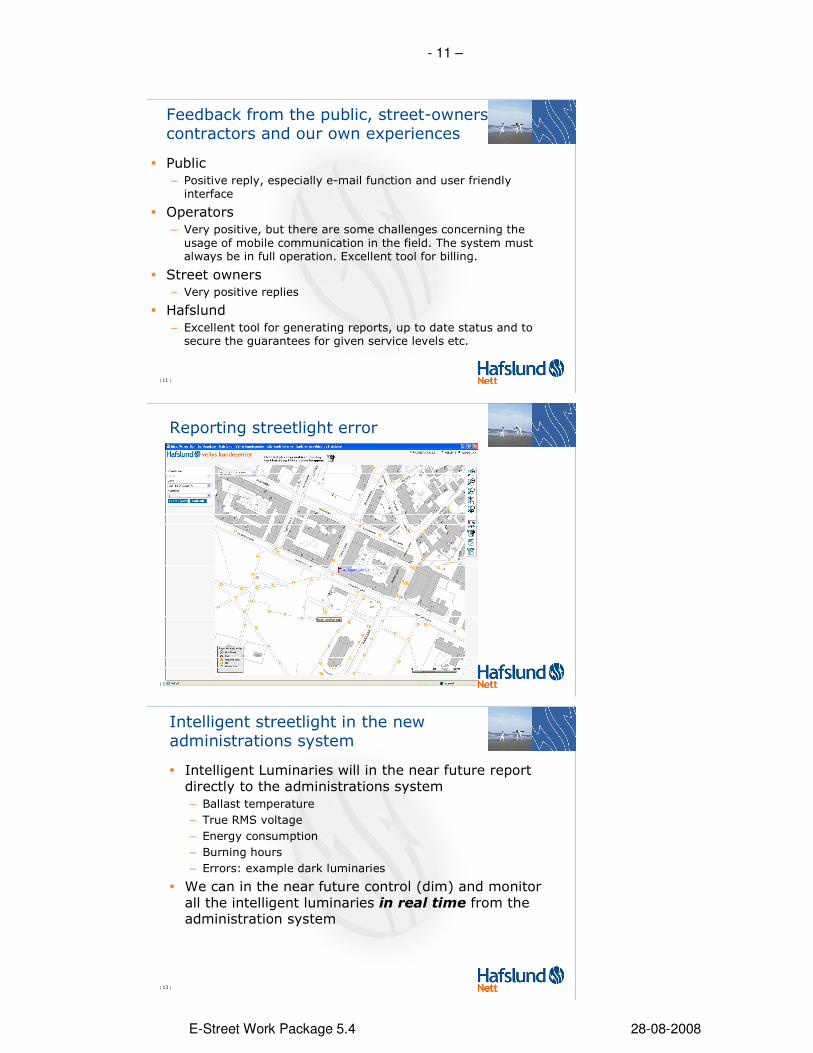
Hafslund Customer Centre
• View streetlight status in the map
• Report errors
• Edit lamps in the map
Customer
center
| 9 |
Contractor
• StreetLight reports
• View historic data
• View work orders
• Close work orders
• Prepare invoice documentationContractor
| 10 |
Hafslund’s solution
ISCU
Kundesenter-applikasjon
ESRI
GeoNis
IFS
Intelligente
Veilys
(kommunikasjonsserver)
Administrasjonssystem for veilys
BEA Web Logic
Adm. databasefor veilys
- 11 –
E-Street Work Package 5.4 28-08-2008
| 11 |
Feedback from the public, street-owners contractors and our own experiences
• Public
– Positive reply, especially e-mail function and user friendly interface
• Operators
– Very positive, but there are some challenges concerning the usage of mobile communication in the field. The system must always be in full operation. Excellent tool for billing.
• Street owners
– Very positive replies
• Hafslund
– Excellent tool for generating reports, up to date status and to secure the guarantees for given service levels etc.
| 12 |
Reporting streetlight error
| 13 |
Intelligent streetlight in the new administrations system
• Intelligent Luminaries will in the near future report directly to the administrations system
– Ballast temperature
– True RMS voltage
– Energy consumption
– Burning hours
– Errors: example dark luminaries
• We can in the near future control (dim) and monitor all the intelligent luminaries in real time from the administration system

- 12 –
E-Street Work Package 5.4 28-08-2008
2 WORKING TOOL FOR MARKET PLAYERS 2.1 Huge savings potential
2.2 Huge saving potentials utilizing new technology Outdated installations increase energy costs and new technology represents a large cost cutting potential in the rehabilitation of outdoor lighting installations. With new installations there is great saving potential when employing new enriching adaptive lighting techniques which are possible with today’s high technology.
Old installations inflict unnecessary yearly costs. By correct investments and utilizing today’s technology it is possible to reduce today’s energy consumption for street and road lighting by as much as approximately 60 %. For Europe as a whole, this stands for about 36 TWh a year. In addition, you also achieve a significant saving on maintenance costs. Recently there has been a tendency towards a shift in the responsibility for costs related to installation and operation of street lighting installations. In Norway this came as a law reform in 1991, the law stated that it is no longer allowed to make cross subsidies of street lighting within the electricity companies. This means that the road keeper have to cover all the costs related to installation and operation of the street light. There are several factors that emphasize the importance of a holistic focus when considering investments in these kinds of installations. Normally public authorities have two different budgets for running and maintaining the installations as well as investing and construction. This does not make it easy for overall consideration of the installations total economical aspects. This is also applicable to adaptive lighting where re-investments, in some cases, can have a “payback time” as short as 5 years or less. When sending out a tender, there is today a public demand that all purchasing and contracts should be in accordance to existing laws of public purchase. It is also important that the tender gives a thorough description of what functional demands should be addressed in a lighting installation, so
that afterwards you can choose the best total solution in terms of both investment costs,
running costs and maintenance costs (ref. LCC). As much as 50-70 % of the original energy consumption can be saved by reinvesting in new technologies where old in-efficient luminaires have been replaced, changed lighting arrangements and the introduction of stepless dimming in relation to adaptive lighting and as much as 70 % in
energy reduction has been achieved. By replacing the luminaires only, between 40-50 % energy reductions is achieved. In addition, by implementing two way communication (luminaires with built-in intelligence), you achieve an accurate prediction of the lamps condition and thereby reduce the need for manual control, and may plan maintenance in a cost effective way. To keep a better track of your installation and secondarily to optimize the priorities for the maintenance of the road, the road keeper should have an electronic record of his installations, based on a digitalized mapping system where each component is registered as individual traceable objects with a geographical reference.

- 13 –
E-Street Work Package 5.4 28-08-2008
2.3 Organizing outdoor lighting
Management of road and street lighting
Road and street lighting place heavy demands on the public road budget. Recent studies in Norway indicates that the daily costs represent about 20-40 % of the total budget, half of this figure covers the energy costs and the other half goes to running and maintenance. It’s important that the road keeper has control and awareness of the costs. It’s being observed that some road keepers try to reduce their costs by transferring the responsibility to private road keepers and community associations. A complicating factor with such a solution, is that many of these installations are constructed and integrated with the main supply grid. It can therefore be the case that one installation contains several customers. For instance in Norway, the Public Road Authority, (“Statens Vegvesen”) is the road keeper in all of the municipalities. Road lighting guidelines
By writing such guidelines for the diversion of responsibility gives better control for your costs. When introducing guidelines you should also consider making the establishment of road lighting an obligated part of the allowance for constructing roads in the municipality. The guideline can describe the correct work method for securing quality and these should follow the municipalities’ general regulations of road construction. This paper will then represent a minimum demand for (private) initiated installations to be connected to the public grid. The guideline should consider the following subjects: * Description of public measures. Where the municipality has made a political or administrative decision for the initiator to include road lighting as an obligated and included cost for the road construction, the cost for new establishment will be transferred to the initiator. * The quality standards for luminaires and technical equipment must be described (see notes) *The municipality should define the desired level of lighting on the road in accordance with international and national regulations with recommendations and set limits for the use of energy related to defined luminaires. *Considerations of light pollution issues should be described *Describe which parameters should dictate when to switch on/off the luminaires and under which conditions the installation should operate at dimmed levels. *Where in the existing grid system it should be derive power. For installations with two way communication, describe the requirements for the communication equipment and define the protocols for communication to the administrative system. *Specifications of correct integration points for energy measurements. (How will the energy consumption of the installation be measured?). With the rapid development of luminaries and lighting control gear it is of great importance to keep the guidelines”up to date”. Accomplishing public demands
To comply with the regulations concerning the removal of hazardous PCB from lighting installations, it is especially important to emphasize to the responsible authorities the energy saving potential that can be achieved by upgrading the technology of their installations.
- 14 –
E-Street Work Package 5.4 28-08-2008
New installations have to comply with today’s regulations for lighting levels, electrical installation regulations and environmental demands. The proposed EU “ECO-directive” also sets demands for the “lifecycle analysis”, lead and mercury free installations and a ban against ineffective electromechanically control gear. Let your new lighting installation be a class A installation! By implementing these changes you prepare for future European recommendations and regulations concerning the environment and the energy reduction. Financial considerations
The calculation of return on Investment is important to identify today’s energy cost, including the cost of both electrical power consumption and of energy used. Furthermore a lifecycle calculation will have to consider the future changes in cost.. The calculations will use the “present value method” with discounted cash flow or by the use of continuous cash flow analysis. For the calculation of financial costs or of financial payback, the public rate of calculation should be utilized. By utilizing new types of luminaires and control gear you can prolong lifetime values so that the annual maintenance costs is reduced. In total one could say that by reinvesting in new technology and planning according to today’s lighting level demands, the road keeper will achieve a payback on invested capital within a time period of 4-6 years depending on the initial situation,; energy price level, and the level of maintenance costs involved. (Whatever the situation this is a short payback time compared with other safety improvement measures.)
3 TOPOLOGY OF ADMINISTRATIVE SYSTEMS
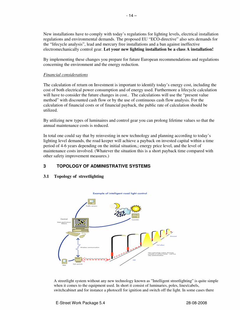
3.1 Topology of streetlighting
A streetlight system without any new technology known as ”Intelligent streetlighting” is quite simple when it comes to the equipment used. In short it consist of luminaries, poles, lines/cabels, switchcabinet and for instance a photocell for ignition and switch off the light. In some cases there

- 15 –
E-Street Work Package 5.4 28-08-2008
are one or a few photocell which is centralized, and the signals for ignition and switch off are sendt through signal cables to a contactor in each switch cabinet. Introducing intelligent streetlighting, the street light system will be a lot more complex with new technology in both luminaries and switch cabinets as well as new datasystems controlling the streetlights.
3.2 Communication
There are several technologies available for communicating with street lighting installations. The three dominant technologies are:
• Radio/telephone
• Fiber
• Powerline
All these technologies are today utilizing digital signalling. Prior radio/telephone systems operated on an analogic basis, in some cases still in use in old systems.
Description of a Telemanagement system"
A telemanagement lighting system that makes for compelling returns on investment and provides the benefits listed above can be largely achieved today with the integration of “off-the-shelf” products. The system consists of 3 main parts:
The Outdoor Luminaire Controller
First of all luminaires equipped with dimmable light sources are an important part of the system. The basic set-up is a lamp and dimmable ballast in combination with a controller for the ballast. We call this controller the Outdoor Luminaire Controller (OLC). The lamp system controller is the component that forms the link between the dynamic lighting system and the lamp. Because it is possible to have many different types of links between the lamp system controller and the ballast, standard interfaces have been selected as described before: 1-10V or DALI. This allows products from different manufacturers to be used and exchanged.
OLC specifications:
o (stepless variable) dimming
o switching (on-off) o possibility to measure lamp operating data (nominal data as a basis for alarms) o predictive behavior function based and status indication
o monitoring of ballast and lamp data of including: � lamp status (on/off/dim position) � burning hours � number of starts � electrical characteristics including system operating voltage � power consumption and electric current � fault and status indications � data, communication problems, lamp fault and ballast fault o maintenance operation is necessary for the OLC for testing
o work autonomously as an active communication repeater in the system
o continuous communication monitoring with action (lamp to 100%) in the event of communication failure; o implement programmed actions following an alarm for example reduce lamp voltage after a ‘near end of life’ alarm.

- 16 –
E-Street Work Package 5.4 28-08-2008
For practical reasons it would be desirable if OLC’s are to be used for ‘conventional’ applications, i.e. as switching/dimming/communication units for existing lighting luminaires with conventional ballasts.
The Segment controller
The luminaires are connected to a power supply cabinet and communicate with the Segment Controller (SC). This basic infrastructure consists of an intelligent controller that handles various functions like scheduling/control/data logging and alarm handling per segment, as well as the WAN communications to the management system. The segment controller is the main component in the local lighting installation and should be based on open technologies so it is possible to easily modify or expand it in the future. The following specifications are based on systems currently available in the market which have the following in common:
o The segment controller must work as a network interface with repeater functionality, a web server, and have the option of accessing an ANSI 709.2 network from an IP network and/or the Internet independent of the underlying infrastructure
o The segment controller must be able to log alarms, act in response to alarms and prioritize them. If bad weather or accidents occur then a signal should be sent to set the lighting to 100% on. o There should be an embedded calendar and scheduling functions for both absolute as well as astronomical clocks
o It should be able to operate as a web server, and have the ability to access and program functions based on SOAP/XML (Simple Object Access Protocol), and customized web pages
o Automatic collection and logging of data from connected OLC’s
o Capability to automatically upload new software and data to the OLC following an update from the central system or a local update without the need to be online
o The management, processing and implementation of inputted scenarios and clock programs including the option of bypassing these functions
o Availability of digital inputs and outputs including relay control. Possible applications include;- � door open/closed contact; � pulse counter (kWh); � external alarm reporting outside cabinet; � linking of additional external triggers. o Availability of IP (Internet Protocol) network interfacing using an ANSI 709.2 (Local Operating Network on the street side) interface to various communication carriers and protocols; o Availability to incorporate a GPRS module and/or modem or any other ADSL modem
The Central Management System
The central management system (CMS) is used to control the segments and manage the data coming from the segment controllers. This third and very important part of the system is what we also call the IT interface. When there are two or three segment controllers in the network it is very easy to manage them, but very quickly it becomes impossible to do this manually when the numbers increase. Specifically if the segment controllers reside in various different locations, with different service providers and WAN connection types it rapidly becomes difficult to manage.

- 17 –
E-Street Work Package 5.4 28-08-2008
The software solution in a telemanagement system should allow for the management of the system as well as for using the data in an existing IT environment. The functions this interface provides are the following:
• It manages the WAN communications and keeps track of where the segment controllers are and what the service provider is, how you can reach them and how healthy they are.
• It collects the data from your segment controllers and keeps track of when the data was collected, if all data was collected and if the right data was collected.
• It organizes and stores the data coming from the equipment. Terabytes of data are collected over a year and to find relevant data quickly then it needs to be organized and stored in a structured way.
• It synthesizes new data. The field data is usually not in the right format and not the information needed to take fact based decisions. Users are not interested in pulses but rather in the amount of kWh used. The number of burning hours is useful, but what really interest’s a person is when to replace the bulbs. The recalculation part of the system needs that functionality.
• The data needs to be used in existing IT/GIS applications.
1-10V1-10V
MAINS
MAINS
Phase cut
CENTRAL
To other armaturesTo other segment controllers
COM.
PROTOCOL
SEGMENT
BOX
SEGMENT
BOX
CONOLC OLC
OLC
DV DV
���� Traffic information
Mains
Foon
GSM
Fibre
TCP / IP
RS485
RF
GPRS
LIGHTCEL
1-10V1-10V
MAINS
MAINS
Phase cut
CENTRAL
To other armaturesTo othersegment
COM.
PROTOCOL
SEGMENT
BOX
SEGMENT
BOX
SEGMENT
BOX
SEGMENT
BOX
CONOLC OLC
OLC
DV DV
Traffic information
Mains
Foon
GSM
Fibre
TCP / IP
RS485
RF
GPRS
LIGHTCEL
1-10V1-10V
MAINS
MAINS
Phase cut
CENTRAL
To other armaturesTo other segment controllers
COM.
PROTOCOL
SEGMENT
BOX
SEGMENT
BOX
SEGMENT
BOX
SEGMENT
BOX
CONOLC OLC
OLC
DV DV
���� Traffic information
Mains
Foon
GSM
Fibre
TCP / IP
RS485
RF
GPRS
LIGHTCEL
1-10V1-10V
MAINS
MAINS
Phase cut
CENTRAL
To other armaturesTo othersegment
COM.
PROTOCOL
SEGMENT
BOX
SEGMENT
BOX
SEGMENT
BOX
SEGMENT
BOX
CONOLC OLC
OLC
DV DV
Traffic information
Mains
Foon
GSM
Fibre
TCP / IP
RS485
RF
GPRS
LIGHTCEL
Overview of the system configuration
The system needs to function even if the central management system is failing or the WAN communication prevents it from sending control messages to the segment controller. This is possible because the system consists of a network of decentralized intelligence in the segment controller and even in the OLC for automatic operation. Using this “distributed intelligence” means that no central controller is needed to allow the system to function efficiently and safe.
The OLC’s check the lighting, either by using information from ballasts or by using external signals. The working parts of the system can keep functioning autonomously if one of the system components or fails.

- 18 –
E-Street Work Package 5.4 28-08-2008
Radio/telephone Telephone /radio communication is undergoing rapid development and changes. Prior airborne GSM solutions now currently are provided with GPRS, 3G or EDGE. For fixed wire/twisted pair solutions ADSL is more commonly used than the previous ISDN. The different capacity, flexibility and tariffs will define your choice.
Fiber Fiber-cable is developing in competition with existing telephone and video-cable installations. In many cities fiber is available at reasonable pricing for long distance transfer of data. Fiber is in use for street lighting installations between the switch cabinet and central database.
Powerline
Powerline is a relatively new technology. It utilizes the existing power-cabel for high frequency signalling. Powerline is now available for the private home market in applications for i.e local broadband internet connections. In street lighting installations it is commonly used between switch cabinet and the luniniares.
3.3 System integrations of databases
The Management software forms the part of the solution where it all comes together. The software consists of a database and various applications around it that together form the management system. The software should give complete control over the Outdoor Lighting System and the data coming from it. It should be your choice to host the management platform on your own server or use an Application Service Provider (ASP) for the management system. The management software provides all the functions needed to keep your solution efficient, well maintained and safe. The software should enable you to:
• collect, organize and store the data coming from the street
• recalculate and rework the data so it becomes useful information
• set the schedules, data loggers and alarm options in your system
• manage the Wide Area Network as well as the control network in the street
• present the data in the way that you like it best, using a normal web browser on a standard PC
• present data to other applications that you already have like billing or maintenance systems using standard web technology and SOAP/XML.
The software has four important functions; a Data Engine, the Expert Engine, the data interface and the Front-end. All software should be developed using best practice and state of the art Open technology like SQL and Flex.
3.3.1 Database and data collection
The heart of the software is formed by a SQL database where the data coming from the different sources, like lamps, feeder pillars and sensors is organized and stored. The data gathering software should be developed with GPRS in mind and is therefore a very “lean” solution that will not transfer one byte too much. After all, over GPRS the data has to be paid by the byte. The database normally stores information in four different sections containing information like: Streetlight attributes
• Lamp name
• Lamp ID/Location/GPS position
• Power

- 19 –
E-Street Work Package 5.4 28-08-2008
• Owner
• Type
• Metering ID, if lamp itself is doing metering Feederpillar attributes
• Feederpillarname
• Area (where it belongs)
• Metering ID if there is a meter installed in the feederpillar
Streetlight data (data coming from the lamps)
• Ballast value
• Burning hours
• State
• Lamp feedback
• Energy count Feederpillar data (data coming from the feederpillars
• Energy count
• State and door status To store the right data in the database in a timely manner a Data Collector gathers the data from the Segment Controllers. The Data Collector pre-processes this and then organizes it in the database. Very important is the scalability so the size of the solution is practically irrelevant. It should be possible to run 35 lamps and one feeder pillar or 55.000 lamps on 800 feeder pillars with similar performance in the management system.
3.3.2 Combining data and experience
To be able to use the data in the right way and combine it with all the expertise available there should be a module that continuously calculates, combines and interprets your data to help answer questions like:
• why do some lamps fail unexpectedly
• present the data in the way that you like it best using a normal webbrowser on a standard PC
• what causes intermittent problems and how can they be solved
• does a group replacement make more sense than a individual lamp change
• how can my schedules be optimized to save even more energy
• are there any power supply issues in my network
3.3.3 Sharing the data
If the information from your street light system needs to be available in other (enterprise) applications, like your maintenance systems, billing system or financial applications a data interface will take care of it. It should be able to present any information available in any standard format you wish to other software packages. If you need to control items in your system from another application, like a traffic management system, accident detection application or weather feeds from the internet it is also done through this data interface as well. The data interface should be able to cope with all standard ways of exchanging information known today.
3.4 Intelligent streetligting – at what level ?
Streetlighting system is possible to operate in different degree of intelligence depending on the customer´s needs, topology of electrical network, purchase and operating costs and etc. Intelligence of streetlighting systems is, according to the presence of actuators and measuring elements, located in the switch cabinet or in the luminaire or combined.
- 20 –
E-Street Work Package 5.4 28-08-2008
3.4.1 Switch cabinet
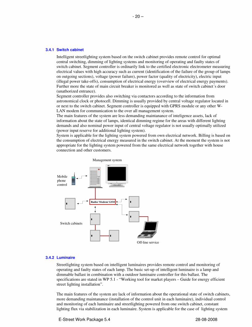
Intelligent streetlighting system based on the switch cabinet provides remote control for optimal central switching, dimming of lighting systems and monitoring of operating and faulty states of switch cabinet. Segment controller is ordinarily link to the certified electronic electrometer measuring electrical values with high accuracy such as current (identification of the failure of the group of lamps on outgoing sections), voltage (power failure), power factor (quality of electricity), electric input (illegal power take-offs), consumption of electrical energy (overview of electrical energy payments). Further more the state of main circuit breaker is monitored as well as state of switch cabinet´s door (unathorized entrance). Segment controller provides also switching via contactors according to the information from astronomical clock or photocell. Dimming is usually provided by central voltage regulator located in or next to the switch cabinet. Segment controller is equipped with GPRS module or any other W-LAN modem for communication to the over all management system. The main features of the system are less demanding maintanance of inteligence assets, lack of information about the state of lamps, identical dimming regime for the areas with different lighting demands and also nominal power input of central voltage regulator is not usually optimally utilized (power input reserve for additional lighting system). System is applicable for the lighting system powered from own electrical network. Billing is based on the consumption of electrical energy measured in the switch cabinet. At the moment the system is not appropriate for the lighting system powered from the same electrical network together with house connection and other customers.
PC Server310
HEWL ET TPACKA RD
Radio/ Modem/ GSM
Management system
Switch cabinets
Mobilephonecontrol
Off-line service
3.4.2 Luminaire
Streetlighting system based on intelligent luminaires provides remote control and monitoring of operating and faulty states of each lamp. The basic set-up of intelligent luminaire is a lamp and dimmable ballast in combination with a outdoor luminaire controller for this ballast. The specifications are stated in WP 5.1 - “Working tool for market players – Guide for energy efficient street lighting installation”. The main features of the system are lack of information about the operational state of switch cabinets, more demanding maintanance (installation of the control unit in each luminaire), individual control and monitoring of each luminaire and streetlighting powered from one switch cabinet, constant lighting flux via stabilization in each luminaire. System is applicable for the case of lighting system

- 21 –
E-Street Work Package 5.4 28-08-2008
powered form the same electrical network together with house connections without metering in the cabinet.
3.4.3 Switch cabinet and Luminaire
Inteligence of the system allows to control and monitor operational status in the switch cabinets as well as in each luminaire. The main feature of the system is complete information of the maintened assets stated in WP 5.1 – ”Working tool for market players – Guide for energy efficient street lighting installation”. System is applicable in those areas, where consumed electricity is measured in the switch cabinet whereas it is demanded to utileze all advantages of individual communication with luminaires. Open technology should be used so the complexity can be added step by step.

- 22 –
E-Street Work Package 5.4 28-08-2008
4 ADMINISTRATIVE ASPECTS AND CHALLENGES The number of streetlights in a city or within a municipality is often of a great number, it is therefore crucial to have a system to administrate this assets. Introduction of different types of intelligent streetlight systems within the same city or munipality demands a common interface of all the systems for the operator and other users.
The infrastructure can also be suitable for other purposes, such as managing Trafficlights. The system should be expandable and it should have the flexibility to be used for other purposes.
4.1 Operation and maintenance
Operation and maintenance of the street light is a huge challenge because of the large number of components in a street light system. It is therefore required to install a system which take care of all the information concerning the state of each component, including information about ongoing activities and historical information. Hence of this each luminare/component must have a unique objectnumber in the database. There are various scenarios on the maintenance strategy you can implement. Of course there is the “run-to-failure” maintenance scenario sometimes called "crisis maintenance" in this form the management is done based on the actual status of the overall system. Most management solutions work this way. Second it is possible to set up periodic preventive maintenance, or "historical" maintenance. This is where the history of each lamp type is analyzed and periodic replacement is scheduled before the statistically expected problems occur. Most sophisticated is to set up predictive maintenance, which is based on the determination of the lamps condition while in operation. By using the information from the database some solution make it possible to sense the symptoms by which the lamp warns that it will break down. The latest innovation in the field of maintenance is called predictive maintenance or so-called pro-active maintenance, which uses a variety of technologies to extend the burning hours of the lamps and to virtually eliminate reactive maintenance. The major part of the pro-active tools is what is called "root cause failure analysis". The fundamental causes of lamp failures like frequent power supply issues can be identified and corrected and using this technique failure causes can be gradually engineered out. The maintenance part of the software should offer a fully automated work order and workflow management system as well as the possibility for tracking and tracing maintenance task in various ways.
4.2 Energy metering and monitoring
The energy consumption is rarely measured with a meter, but calculated based on run hours and installed effect. This gives an inaccurate metering, thus both the grid company and the streetlight owner wish the streetlight to be measured with an energy meter. The easiest way to do this is by installing a meter in the switch cabinet, but this require that the streetlight is built as an electrical network, and not integrated with other types of energy consumptions. Intelligent streetlighting gives the possibility to meter the energy consumption in each luminare, hence the streetlight owner is not dependent on having the meter in the switch cabinet. However there are some challenges that have to be solved with this type of new technology:
• The technology is not yet authorized to use for billing purposes
• The meter has to be certified, and this can be an time consuming and expensive process
• Ownership and maintaince responsibilities of the meter in the luminaire.

- 23 –
E-Street Work Package 5.4 28-08-2008
4.3 Human/machine interface
The public and the serviceproviders are both dependent on information about the streetlight from the streetlight operator. The public are interested in a system for fault reporting on the street lighting, and to observe the status on each street light. The serviceproviders are interested in a system for accurate information on the luminares and reported failures. They are also dependent on a system for reporting the work that has been done regarding failures and other relevant information. The interface for the user should be a GIS system. GIS is very important for maintenance services, it makes it easier to find and identify the failures. The user interface on the web should be simple and easy to handle for everybody.
The front end software allows you to find, manipulate and view the information from your street light system. It will also let you change the settings in your system and monitor the health of your networks. Normally the front end software is modular and allows for multiple extended functions when needed. In the basis the software should offer a complete Street Light Management System with all basic functionality integrated. It should allow you to look at multiple sites, check and set your schedules, analyze your lamp and equipment behavior as well as your energy usage. It has a simple reporting mechanism that allows for pre-defined reports to be generated and printed. Color coding and letters in one screen should give a first overview and general impression on the segment controller and the lamps. By Clicking on the various items information regarding the object you clicked should be presented to you in lists, tables or graphs.
4.4 Principal description
Below find a principal system sketch with adjoining system where communication channels are to be established. The communication channels are in the sketch shown in red in a “common” intermediate layer solution.

- 24 –
E-Street Work Package 5.4 28-08-2008
It is recommended that the communication channels should be a part of the administration system in an implemented solution. This will be favourable for the customer-center through an effective and accurate feed-back to the public on errors on the street lighting, and an improvement of the economic system due to better control with the different suppliers. The solution requires an automatic administration system for technical and economical reporting. The system will in most cases be integrated with the existing IT solutions. The main functionality will be:
1. Administration system for street lighting 2. Customer service solution including a communication facilites 3. Active control of street light and integration to the Customer system and energy metering 4. Integration to order system and a fully developed CRM-system.
The custumer-service application shall include a web/internet portal adjusted to non-professional user (public) for access and directly reporting of errors etc. Open techonology should be used so the complexity can be added step by step.
4.5 Administration system for street lights
The administration system shall consist of an administration database for street lighting, communication channels to surrounding (connected) systems (intermediate layer), an separate user applications with construction record, task list with job orders, plus history and reporting.
The administration database have a data model adjusted to the data delivered from the functional controlled street lighting operation range. Available data from the traditional street lighting is also to be stored in the database. The administration database shall handle construction structure and all the basis data with attributes for both the functional controlled and the conventional street lighting. Data from the user application in the administration system shall also be stored in the database. It is important that the different communication channels/integrations to the surrounding systems are based on open solutions. The software should allow for management of two main hierarchies for user Groups: one for access to the Front-end (so users can log in to the web site and view designated sections and pages) and one for the Back-end Administration access.
4.5.1 Task list
The system offers a task list with funconality, such as:
• An order functionality with a task register (a list of job orders).
• A list over customer information for the fixture identities is to be generated.
• Predefined templates for different tasks shall be available.
• The solution is to contain a calendar- function with a display of job orders.
• A given constructor shall be limited only to see his own tasks.
• The job orders are to be given mutual priority.
• The purchaser of tasks shall be able to see the status and the progress for his orders.
• Orders have to be related to individuals or groups in the construction register (i.e. switch cabinet).
• The service supplier must be able to print out finished tasks with the date and the failure cause.
• The service supplier must be able to print out a prioritized list for correction of errors for the fixtures
- 25 –
E-Street Work Package 5.4 28-08-2008
4.5.2 History
The administration system has to handle reporting of condition reports from the service suppliers, with the following-up of remarks. The remarks are to be categorized depending on the error. The task registers must report back with a joint history. It shall also be possible to register special history for individual orders in the task register. The history from completed job lists is to be related to the fixture identity. The adm. system shall present the history generated from the functional controlled street lighting.
4.5.3 Reporting
Since reporting is a very import part of the system there should be an extension that allows you to build your own reports. There should be functions to set up the reporting the way your organization and your service providers require it with your fonts, logo’s and lay-out. Ideal is a WYSIWYG editor to make your report layouts and allows for different output formats like .pdf or word.
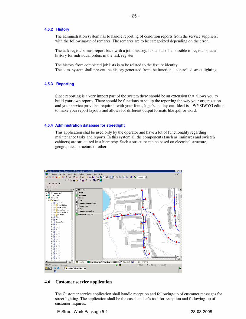
4.5.4 Administration database for streetlight
This application shal be used only by the operator and have a lot of functionality regarding maintenance tasks and reports. In this system all the components (such as liminares and swictch cabinets) are structured in a hierarchy. Such a structure can be based on electrical structure, geographical structure or other.
4.6 Customer service application
The Customer service application shall handle reception and following-up of customer messages for street lighting. The application shall be the case handler’s tool for reception and following-up of customer inquires.

- 26 –
E-Street Work Package 5.4 28-08-2008
The application shall have a web-based map interface for visualization of street lighting with accompanying attribute/quality data (as errors, dimming etc). The solution shall use the standard formats Shape, SOSI and Oracle Spatial as data source for the map presentation. The application will be related to a “living” map. It means that the map will be updated/changed frequently. Therefore it is a neccasary that the Customer service application can relate directly to the primary data source without converting to a proprietor format. The Customer service application shall present data from the administration database for street lighting in a way that supports the operators proceedings. It will be given access to general construction data, status information, overview of ongoing tasks and history etc. from the administration database.
4.7 Data collection from street light
Functional controlled street lighting The system must handle fixtures from different intelligent streetlight suppliers. Suppliers built their solutions on different types of standards and technologies for instance LNS-database (a database solution from Echelon) for exchange and storage of data. In connection with the introduction of a common administration system, the existing street lighting databases will be used as a data source. In the next phase, the existing system will be omitted, and the administration system will be related directly to each fixture, but still via a concentrator (subcentral). A common used structure is based on two-way communication of data through the luminaries power supply , so called “power line communication”. The information to and from the different luminaries are transferred to a concentrator located in the fixture’s electrical supply (switch cabinet). The concentrators then communicate, via telephone (GPRS with MDA Mobil Data Access) with the central database or via fibre optic cables.
Traditional street lighting The fixtures and the attributes is registered in the cartographic information. It is important that the luminaries have the right type of attributes, for instance x- and y coordinates.

- 27 –
E-Street Work Package 5.4 28-08-2008
Further, data from some energy meters for traditional street lighting is to be collected. Here, an energy meter which is connected to the same type of concentrator as for the functional controlled light is used. This way the collection of data will be similar, but with limited data size on the concentrator.

- 28 –
E-Street Work Package 5.4 28-08-2008
5 UPGRADING INSTALLATIONS
5.1 Upgrading of outdated installations
Throughout Europe you find miles of outdated installations. Today this represents an enormous
energy saving potential, and at the same time in many situations, do not solve the lighting task
in a satisfactory way. New technology represents new possibilities.
Remember: Retrofitting of old installations can utilize up to 50-70 % energy reductions, in
addition there are the reduced running costs! Introducing new technology does not necessarily demand a reconstruction of the electrical supply. For instance existing technology can utilize the existing power distribution grid for communication, in addition to radio and digital mobile communication (GPRS/GMS). When new luminaires are retrofitted it is found that lower power consumption is used to achieve the original lighting levels on the road. New luminaires contain both better optical systems and lighting sources that contribute to more light for less electrical energy, and also contribute to less light pollution (obtrusive light) by directing more of the light onto the road and not the surroundings. An installation designed using the old standards, also has a higher averagely lighting level compared to today’s needs. These improvements in technology allow us to consume less electrical energy and at the same time to achieve adequate road lighting. As the implementation consumes reduced energy then the existing electrical infrastructure is more than capable of supplying the retrofitted luminaires. Since the retrofitting does not involve the electrical grid, the implementation of a control system that demands a separate communication cable will result in a bad return of investment. On the other hand there are alternatives for the feeding of communication. Both radio communication and the so called “PowerLine communication”, are alternatives that do not require any physical connections in addition to what already exists. The main principal is to install a component in the feeder cabinet that communicates, two-ways, with each and every one of the luminaires either by radio waves or by communications signals on the existing power grid.. The component located in the feeder cabinet can be programmed to control and log every luminaries on an individual basis (in some situations only the component in the feeder cabinet can contribute to a significant better control and feedback from the installation, without the upgrading of the luminaries). With this technology one have the opportunity for individual energy logging and updated information on running/maintenance that will contribute to an easier planning of the daily maintenance. A considerable reduction of the municipalities costs for running and maintaining the road lighting installations will be the result of such an investment.
5.2 Adaptive lighting
Road lighting is present to increase the safety of traffic and to enhance the sense of security
for individuals. Previous regulations and guidelines were designed to use the technology that
was available at the time.

- 29 –
E-Street Work Package 5.4 28-08-2008
The basis for all road lighting engineering has been to maintain safety by being able to observe objects on and beside the road. Important factors are the roads geometrical design, complexity, traffic volume and speed. One also has to consider wet surfaces, the presence of pedestrian crossings, parked vehicles, schools etc. All installations were designed in the past based on the worst case scenario which is still valid.
The photoelectric detector was considered as a revolutionary development at the time, and is present in most road lighting installations today. As new technology can adapt the light levels steplessly, new possibilities arise. Modern technology for supervision of the traffic will optimize the lighting, it will also still need to cater for the worst case scenario but should also be able to automatically adapt fully to the current needs. For example if the traffic flow low during the night or if the traffic speed is low during rush hours, or in snowy conditions the reflection from the road surface is so high that the need for lux levels is considerably lower than during wet or dry conditions and so on. The obvious advantage of using adaptive lighting, with built in intelligence, is reduced energy consumption and reporting from the lamp of the current status. This gives better control of the installation and ensures that the equipment actually delivers what is required to the customer which leads to an improvement of the quality of the delivered product, “road lighting”. This can be used to deliver higher quality form the installer organisation. It also makes possible to achieve better fleet management. Better control also gives increased predictability and secondarily it lowers maintenance and running costs, by being able to achieve better planning and better implementation of error corrections in the
installations. Adaptive lighting introduces demands for better energy measurements in the
installations allowing the automatic regulation of both electrical parameters, burning hours and light levels. This will call for a demand for measured installations where metering is not installed today. How this is to be included must be a part of the agenda when an installation is being carried
out. If the same system implements the measurement function and the control function then the communication expenses will be reduced, it will minimise the number of components needed in the
system so reducing costs and simplifying the operation and maintenance.
5.3 Purchase - an important function
Purchase- an important function
Good planning will ensure the foundation for a good lighting installation. Your decisions will
have consequences for more then 20 years into the future, so this obligates a thorough planning
phase. This can mean the need for independent and high quality competence in this phase. For new installations and refurbished installationd it is important to ensure that the tender has an accurate and precise technical description that at the same time doesn’t favour any “brand specific” technology. At the same time it’s important to end up with an installation that in the future can function well, without being dependent of any single supplier or contractor. A good example is to use standard lamp sockets (by instance E27 or E40) and ballasts that can ignite different types of lamps (by instance both metal halide and high pressure sodium lamps). When the project initiator is provided with a good description of the technical functionality this goal is obtainable. When carrying out large investments and/or implementing a ”framework agreement” it is also important to give the administrative system some thought. This system can embrace the control of the installation, gathering of information on energy consumption, log the

- 30 –
E-Street Work Package 5.4 28-08-2008
burning hours of each lamp, link burnt out lamps to a superior mapping system and many other useful functions concerned with documentation and the daily running of a streetlight installation. Often it’s also the road keeper’s job to deliver lighting for parks, pathways, floodlight tracking tracks and so on. It’s important to consider individual demands for these lighting tasks also. In Norway public purchasing is obligated to include a Life Cycle Calculation (LCC) when deciding a purchase. The tender therefore has to specify clearly how these calculations are to be carried out. This will include information on the total efficiency of the system, power loss in the ignition system, efficiency of the lamp, expected decrease of maintenance costs due to extended life times etc.

- 31 –
E-Street Work Package 5.4 28-08-2008
6 LIGHTING CALCULATIONS
Basic lighting aspects
Lighting calculations can initially seem quite simple to perform using today’s computer based
calculation programs. But it takes an experienced lighting planner to make correct assumptions
and premises, and also to interpret the results. Normally several adjustments have to be made
before you receive an optimal result. It’s important to perform genuine calculations for your installation. During rehabilitation it’s important to consider lamp heights and possible “extended mounting brackets”. By switching from old mercury lamps to high pressure sodium lamps it is often possible to decrease one “step” of the installation and still provide for today’s demands for lighting. In these situations lighting calculations should be carried out with an independent counsellor. With a new installation lighting calculations are to be documented so that all demands are being fulfilled. When building new installations you are free to optimize your installation dependent on lamp height and relative placement of the columns. Which demands are to be met when carrying out lighting calculations?
• Independent of the supplier
• Adjustments to the present road geometry and surface
• That it uses the same lamps in the in the planned installation as those used in the calculation.
When ownership is transferred/accepted, measurements should be carried out on the installation to verify that the actual lighting level relates to the deliverable lighting calculations!
TECHNICAL ASPECTS
Open protocols:
1.4 Data collection from street light Functional controlled street lighting
Hafslund Nett AS currently have some 6.500 functional controlled road lighting fixtures from two different suppliers. Both of the suppliers use LNS-database (a database solution from Echelon) for exchange and storage of data. In connection to the introduction of a common administration system, the existing street lighting databases will be used as a data source. In the next phase, the existing system will be omitted, and the administration system will be related directly to each fixture, but still via a concentrator (subcentral). Today’s structure is based on two-way communication of data through the installations power supply , so called “power line communication” The data to and from the different fixtures are transferred to a concentrator located in the fixture’s electrical supply (switch cabinet). The concentrators then communicate, individually for the two systems, via telephone (GPRS with MDA Mobil Data Access) with the central database.

- 32 –
E-Street Work Package 5.4 28-08-2008
a. System integration 1.3 Principal description Below is a principal system sketch with an adjoining system where communication channels/integrations are to be established. The communication channels are in the sketch and shown in red in a “common” intermediate layer solution. The communication channels will be a part of the administration system in an implemented solution, but for this delivery it will be included as a part of both the administration system and the client service application. It means that the integration between the client service application and the Administration database, together with the integration between the client service application and GIS is to be delivered as a part of the delivery “Client service application”. The integration between the Administration database and the functional controlled street light, together with the integration between the Administration database and GIS is to be delivered as part of the delivery “Administration system”.

- 33 –
E-Street Work Package 5.4 28-08-2008
b. Exchange of data and protocols
Open protocols
It is of high importance to make it possible to integrate solutions from several independent providers into
one system that the vendors deliver system based on open protocols. This is also important to fulfil the
requirement of open competition and hence cost control.
Data manipulation for the functional controlled light and energy metering The concentrator (ILON 100), with integrated internet server, handles information from both the functional controlled lighting and the energy meters. All information is transferred and stored in the Echelon LNS database. For safe data transfer between the LNS database and iLon, RC4 encryption of Lon Talk identifications keys is used.
Philips – Unilon Starsense System
Philips uses a superior system with the fabric name “Starsense” Starsense is based on the building automation solution “Unilon” which is build on the LNS database. Kongsberg Analogic – Candelon System
Multilux/Kongsberg Analogic uses a superior system with the fabricname ”Candelon System”. The communication unit S2000 has the following specification: http://www.analogic.no/dokumenter/975-0021-04%20Candelon%20S2000%20Datasheet.pdf Kongsberg Analogic – Candelon System
Multilux/Kongsberg Analogic benytter et overordnet system under fabrikknavn ”Candelon System”.
- 34 –
E-Street Work Package 5.4 28-08-2008
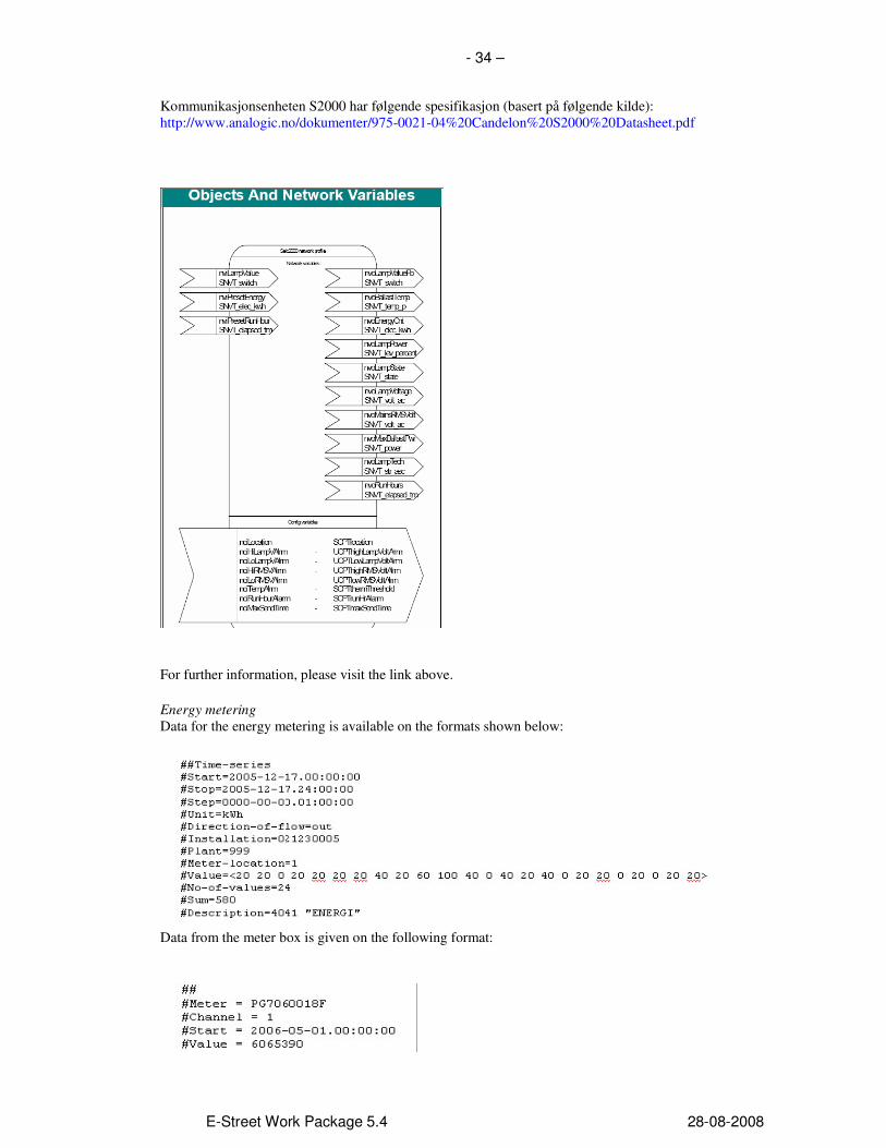
Kommunikasjonsenheten S2000 har følgende spesifikasjon (basert på følgende kilde): http://www.analogic.no/dokumenter/975-0021-04%20Candelon%20S2000%20Datasheet.pdf
For further information, please visit the link above.
Energy metering
Data for the energy metering is available on the formats shown below:
Data from the meter box is given on the following format:
- 35 –
E-Street Work Package 5.4 28-08-2008
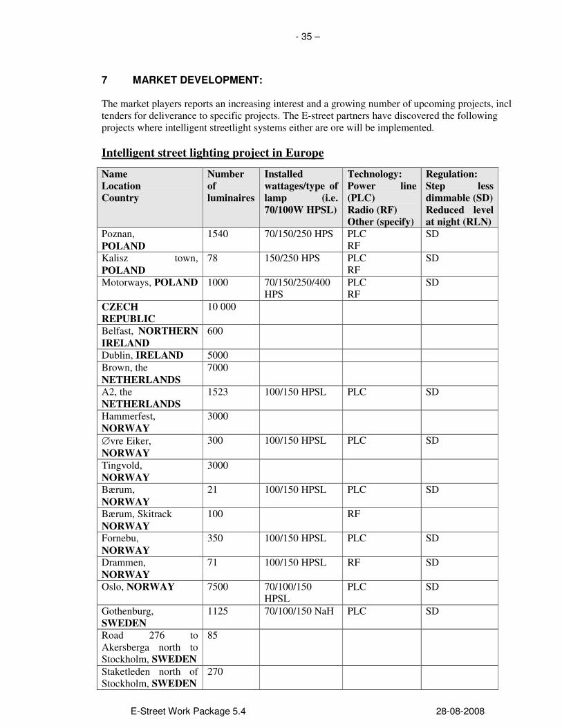
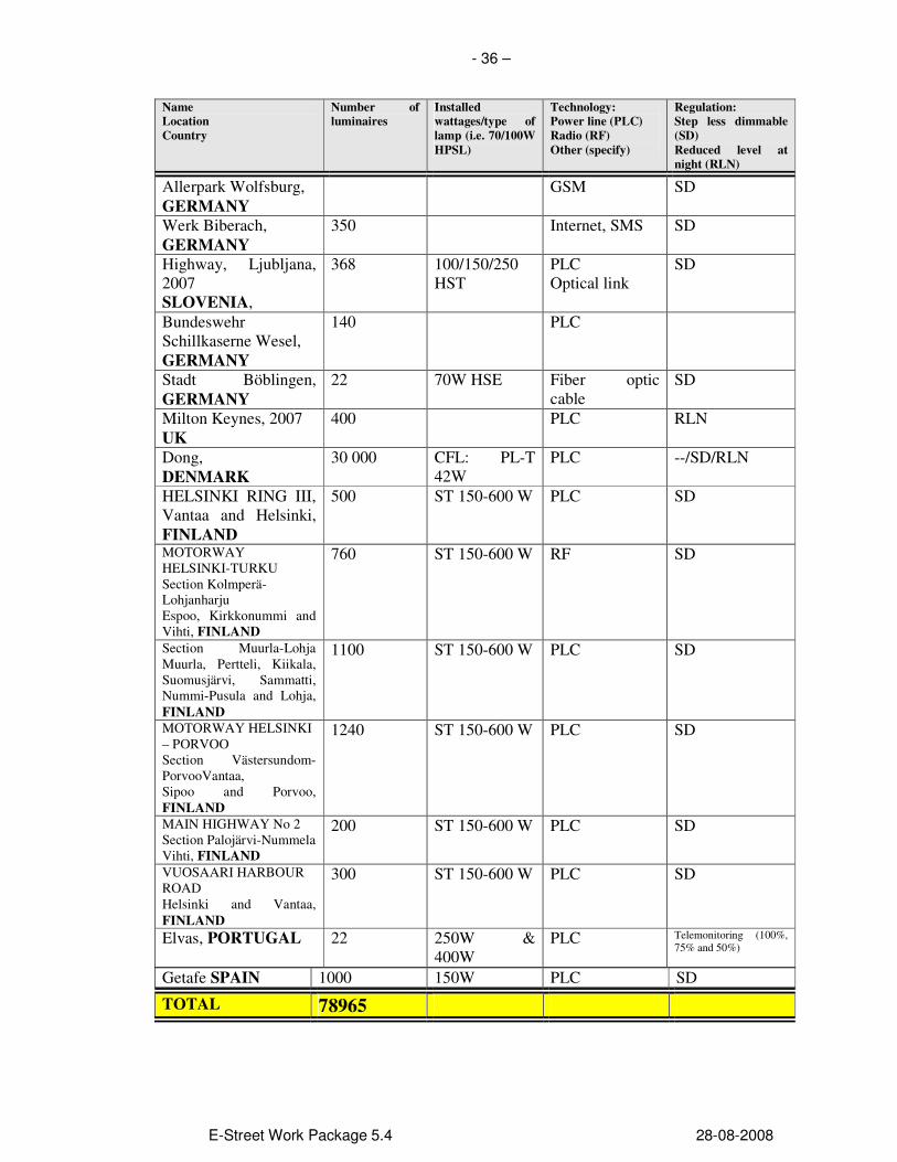
7 MARKET DEVELOPMENT: The market players reports an increasing interest and a growing number of upcoming projects, incl tenders for deliverance to specific projects. The E-street partners have discovered the following projects where intelligent streetlight systems either are ore will be implemented.
Intelligent street lighting project in Europe
Name
Location
Country
Number
of
luminaires
Installed
wattages/type of
lamp (i.e.
70/100W HPSL)
Technology:
Power line
(PLC)
Radio (RF)
Other (specify)
Regulation:
Step less
dimmable (SD)
Reduced level
at night (RLN)
Poznan,
POLAND
1540 70/150/250 HPS PLC RF
SD
Kalisz town,
POLAND
78 150/250 HPS PLC RF
SD
Motorways, POLAND 1000 70/150/250/400 HPS
PLC RF
SD
CZECH
REPUBLIC
10 000
Belfast, NORTHERN
IRELAND
600
Dublin, IRELAND 5000
Brown, the
NETHERLANDS
7000
A2, the
NETHERLANDS
1523 100/150 HPSL PLC SD
Hammerfest,
NORWAY
3000
∅vre Eiker,
NORWAY
300 100/150 HPSL PLC SD
Tingvold,
NORWAY
3000
Bærum,
NORWAY
21 100/150 HPSL PLC SD
Bærum, Skitrack
NORWAY
100 RF
Fornebu,
NORWAY
350 100/150 HPSL PLC SD
Drammen,
NORWAY
71 100/150 HPSL RF SD
Oslo, NORWAY 7500 70/100/150 HPSL
PLC SD
Gothenburg, SWEDEN
1125 70/100/150 NaH PLC SD
Road 276 to Akersberga north to Stockholm, SWEDEN
85
Staketleden north of Stockholm, SWEDEN
270
- 36 –
E-Street Work Package 5.4 28-08-2008
Name
Location
Country
Number of
luminaires
Installed
wattages/type of
lamp (i.e. 70/100W
HPSL)
Technology:
Power line (PLC)
Radio (RF)
Other (specify)
Regulation:
Step less dimmable
(SD)
Reduced level at
night (RLN)
Allerpark Wolfsburg,
GERMANY
GSM SD
Werk Biberach,
GERMANY
350 Internet, SMS SD
Highway, Ljubljana, 2007 SLOVENIA,
368 100/150/250 HST
PLC Optical link
SD
Bundeswehr Schillkaserne Wesel,
GERMANY
140 PLC
Stadt Böblingen,
GERMANY
22 70W HSE Fiber optic cable
SD
Milton Keynes, 2007
UK
400 PLC RLN
Dong,
DENMARK
30 000 CFL: PL-T 42W
PLC --/SD/RLN
HELSINKI RING III, Vantaa and Helsinki,
FINLAND
500 ST 150-600 W PLC SD
MOTORWAY HELSINKI-TURKU Section Kolmperä-Lohjanharju Espoo, Kirkkonummi and Vihti, FINLAND
760 ST 150-600 W RF SD
Section Muurla-Lohja Muurla, Pertteli, Kiikala, Suomusjärvi, Sammatti, Nummi-Pusula and Lohja,
FINLAND
1100 ST 150-600 W PLC SD
MOTORWAY HELSINKI – PORVOO Section Västersundom-PorvooVantaa, Sipoo and Porvoo,
FINLAND
1240 ST 150-600 W PLC SD
MAIN HIGHWAY No 2 Section Palojärvi-Nummela Vihti, FINLAND
200 ST 150-600 W PLC SD
VUOSAARI HARBOUR ROAD Helsinki and Vantaa,
FINLAND
300 ST 150-600 W PLC SD
Elvas, PORTUGAL
22 250W &
400W PLC
Telemonitoring (100%, 75% and 50%)
Getafe SPAIN 1000 150W PLC SD
TOTAL 78965
- 37 –
E-Street Work Package 5.4 28-08-2008
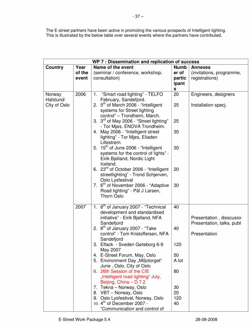
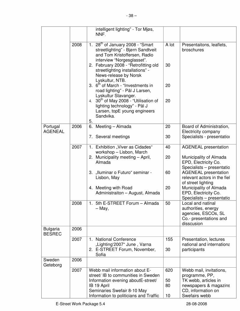
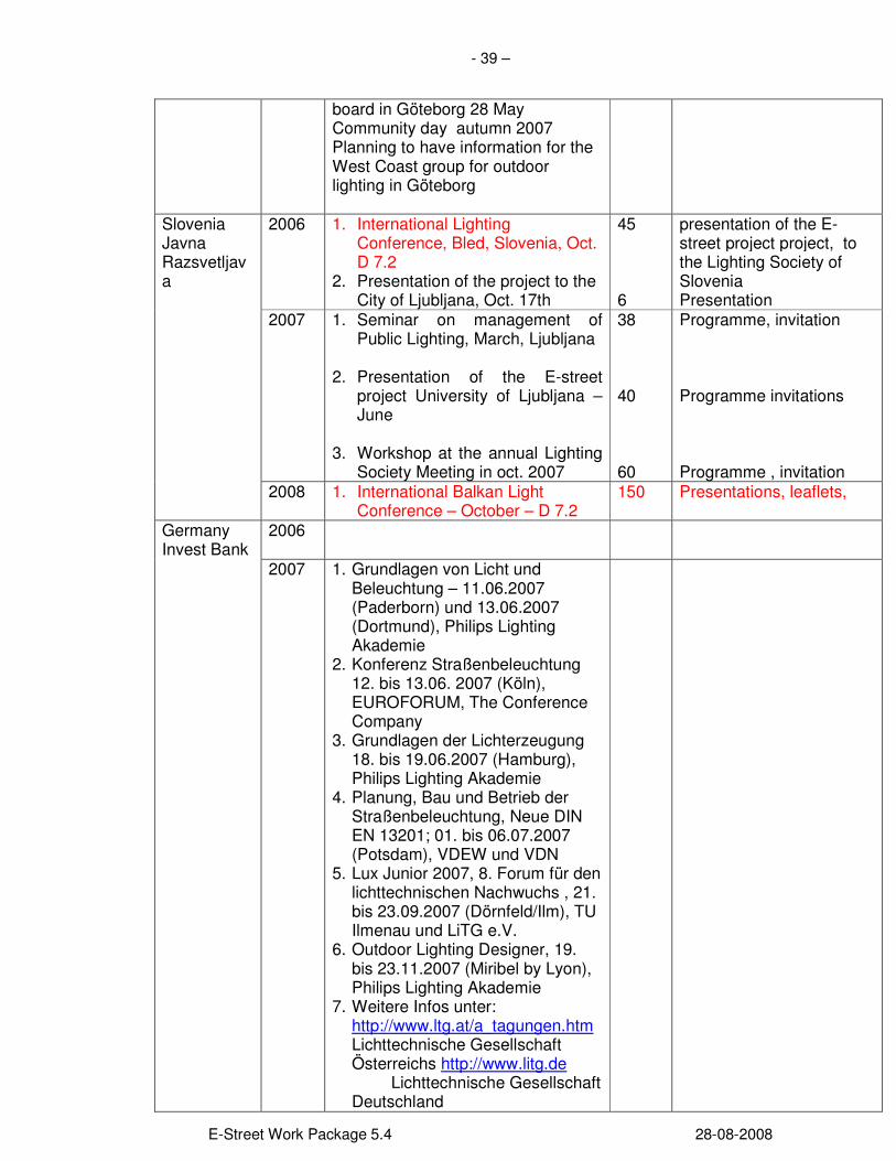
The E-street partners have been active in promoting the various prospects of Intelligent lighting. This is illustrated by the below table over several events where the partners have contributed.
WP 7 : Dissemination and replication of success Country Year
of the event
Name of the event (seminar / conference, workshop, consultation)
Number of participants
Annexes (invitations, programme, registrations)
2006 1. “Smart road lighting” - TELFO February, Sandefjord.
2. 5th of March 2006 - “Intelligent systems for Street lighting control” – Trondheim, March.
3. 3rd of May 2006 - “Street lighting” - Tor Mjøs, ENOVA Trondheim.
4. May 2006 - “Intelligent street lighting” - Tor Mjøs, Eliaden Lillestrøm.
5. 15th of June 2006 - “Intelligent systems for the control of lights” - Eirik Bjelland, Nordic Light Iceland.
6. 23rd of October 2006 - “Intelligent streetlighting” - Trond Schjerven, Oslo Lysfestival
7. 6th of November 2006 - “Adaptive Road lighting” - Pål J Larsen, Thorn Oslo
20 25 25 30 30 20 30
Engineers, designers Installation specj.
Norway Hafslund/ City of Oslo
2007
1. 8th of January 2007 - “Technical development and standardised initiative” - Eirik Bjelland, NFA Sandefjord
2. 8th of January 2007 - “Take control” - Tom Kristoffersen, NFA Sandefjord
3. Elfack - Sveden Gøteborg 6-9 May 2007
4. E-Street Forum, May, Oslo 5. Environment Day „Miljotorget“
June , Oslo, City of Oslo 6. 26th Session of the CIE
„Intelligent road lighting“ July, Beijing, China – D 7.2
7. Tekna – Norway, Oslo 8. VBT – Norway, Oslo 9. Oslo Lysfestival, Norway, Oslo 10. 4th of December 2007 -
“Communication and control of
40 40 120 50 A lot 80 30 20 120 40
Presentation , disscusionPresentation, talks, public Presentation
- 38 –
E-Street Work Package 5.4 28-08-2008
intelligent lighting” - Tor Mjøs, NNF.
2008 1. 28th of January 2008 - “Smart
streetlighting” - Bjørn Sandtveit and Tom Kristoffersen, Radio interview “Norgesglasset”.
2. February 2008 - “Retrofitting old streetlighting installations” - News-release by Norsk Lyskultur, NTB.
3. 6th of March - “Investments in road lighting” - Pål J Larsen, Lyskultur Stavanger.
4. 30th of May 2008 - “Utilisation of lighting technology” - Pål J Larsen, topE young engineers Sandvika.
5.
A lot 30 20 20
Presentaitons, leaflets, broschures
2006 6. Meeting – Almada
7. Several meetings
20 30
Board of Administration, Electricity company Specialists - presentation
2007
1. Exhibition „Viver as Cidades“ workshop – Lisbon, March
2. Municipality meeting – April, Almada
3. „Iluminar o Futuro“ seminar -
Lisbon, May 4. Meeting with Road
Administraiton – August, Almada
40 20 60 20
AGENEAL presentation Municipality of Almada EPD, Electricity Co. Specialists – presentationAGENEAL presentation , relevant actors in the field of street lighting Municipality of Almada EPD, Electricity Co. Specialists – presentation
Portugal AGENEAL
2008 1. 5th E-STREET Forum – Almada – May,
50 Local and natinal authorities, energy agencies, ESCOs, SL Co.- presentations and disscusion
2006
Bulgaria BESREC
2007
1. National Conference „Lighting‘2007“ June , Varna
2. E-STREET Forum, November, Sofia
155 30
Presentation, lectures national and international participants
2006
Sweden Geteborg
2007
Webb mail information about E-street/ IB to communities in Sweden Information evening aboutE-street/ IB 19 April Seminaries Swefair 8-10 May Information to politicians and Traffic
620 50 80 10
Webb mail, invitations, programme, PP, TK webb, articles in newspapers & magazins, CD, information on Swefairs webb
- 39 –
E-Street Work Package 5.4 28-08-2008
board in Göteborg 28 May Community day autumn 2007 Planning to have information for the West Coast group for outdoor lighting in Göteborg
2006 1. International Lighting Conference, Bled, Slovenia, Oct. D 7.2
2. Presentation of the project to the City of Ljubljana, Oct. 17th
45 6
presentation of the E-street project project, to the Lighting Society of Slovenia Presentation
2007
1. Seminar on management of Public Lighting, March, Ljubljana
2. Presentation of the E-street
project University of Ljubljana –June
3. Workshop at the annual Lighting
Society Meeting in oct. 2007
38 40 60
Programme, invitation Programme invitations Programme , invitation
Slovenia Javna Razsvetljava
2008 1. International Balkan Light Conference – October – D 7.2
150 Presentations, leaflets,
2006
Germany Invest Bank
2007
1. Grundlagen von Licht und Beleuchtung – 11.06.2007 (Paderborn) und 13.06.2007 (Dortmund), Philips Lighting Akademie
2. Konferenz Straßenbeleuchtung 12. bis 13.06. 2007 (Köln), EUROFORUM, The Conference Company
3. Grundlagen der Lichterzeugung 18. bis 19.06.2007 (Hamburg), Philips Lighting Akademie
4. Planung, Bau und Betrieb der Straßenbeleuchtung, Neue DIN EN 13201; 01. bis 06.07.2007 (Potsdam), VDEW und VDN
5. Lux Junior 2007, 8. Forum für den lichttechnischen Nachwuchs , 21. bis 23.09.2007 (Dörnfeld/Ilm), TU Ilmenau und LiTG e.V.
6. Outdoor Lighting Designer, 19. bis 23.11.2007 (Miribel by Lyon), Philips Lighting Akademie
7. Weitere Infos unter: http://www.ltg.at/a_tagungen.htm Lichttechnische Gesellschaft Österreichs http://www.litg.de Lichttechnische Gesellschaft Deutschland
- 40 –
E-Street Work Package 5.4 28-08-2008
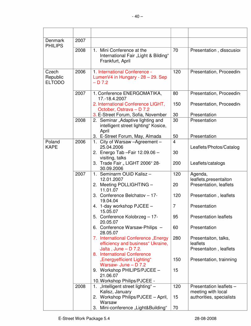
2007 Denmark PHILIPS
2008 1. Mini Conference at the International Fair „Light & Bilding“ Frankfurt, April
70
Presentation , disscusion
2006
1. International Conference - LumenV4 in Hungary - 28 – 29. Sep – D 7.2
120 Presentation, Proceedings
2007
1. Conference ENERGOMATIKA, 17.-18.4.2007
2. International Conference LIGHT, October, Ostrava – D 7.2
3. E-Street Forum, Sofia, November
80 150 30
Presentation, Proceedings Presentation, Proceedings Presentation
Czech Republic ELTODO
2008 2. Seminar „Adaptive lighting and intelligent street lighting“ Kosice, April
3. E-Street Forum, May, Almada
30 50
Presentation Presentation
2006 1. City of Warsaw –Agreement – 25.04.2006
2. Energo Tab –Fair 12.09.06 – visiting, talks
3. Trade Fair „ LIGHT 2006“ 28-30.09.2006
4 30 200
Leaflets/Photos/Catalog Leaflets/catalogs
2007 1. Seminarm OUiD Kalisz – 12.01.2007
2. Meeting POLLIGHTING – 11.01.07
3. Conference Belchatov – 17-19.04.04
4. 1-day workshop PJCEE – 15.05.07
5. Conference Kolobrzeg – 17-20.05.07
6. Conference Warsaw-Philips – 28.05.07
7. International Conference „Energy efficiency and business“ Ukraine, Jalta , June – D 7.2.
8. International Conference „Energyefficient Lighting“ Warsaw- June – D 7.2
9. Workshop PHILIPS/PJCEE – 21.06.07
10. Workshop Philips/PJCEE -
120 20 120 7 95 60 280 150 15
Agenda, leaflets,presentaiton Presentation, leaflets Presentation , leaflets Presentation Presentation leaflets Presentation Presentaiton, talks, leaflets Presentaiton , leaflets Presentation, trainning
Poland KAPE
2008 1. „Intelligent street lighting“ – Kalisz, January
2. Workshop Philips/PJCEE – April, Warsaw
3. Mini-conference „Light&Building“
120 15 70
Presentation leaflets – meeting with local authorities, specialists
- 41 –
E-Street Work Package 5.4 28-08-2008
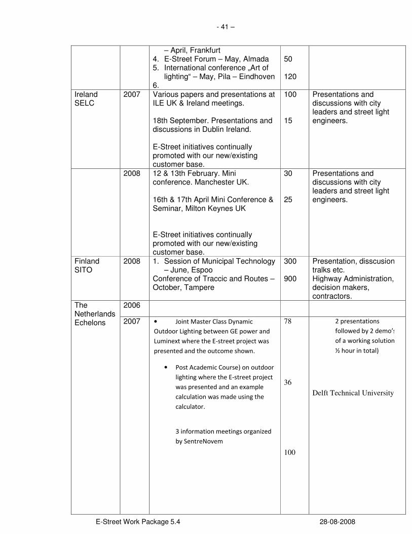
– April, Frankfurt 4. E-Street Forum – May, Almada 5. International conference „Art of
lighting“ – May, Pila – Eindhoven 6.
50 120
Ireland SELC
2007 Various papers and presentations at ILE UK & Ireland meetings. 18th September. Presentations and discussions in Dublin Ireland. E-Street initiatives continually promoted with our new/existing customer base.
100 15
Presentations and discussions with city leaders and street light engineers.
2008
12 & 13th February. Mini conference. Manchester UK. 16th & 17th April Mini Conference & Seminar, Milton Keynes UK E-Street initiatives continually promoted with our new/existing customer base.
30 25
Presentations and discussions with city leaders and street light engineers.
Finland SITO
2008 1. Session of Municipal Technology – June, Espoo
Conference of Traccic and Routes – October, Tampere
300 900
Presentation, disscusion, tralks etc. Highway Administration, decision makers, contractors.
2006 The Netherlands Echelons 2007 • Joint Master Class Dynamic
Outdoor Lighting between GE power and
Luminext where the E-street project was
presented and the outcome shown.
• Post Academic Course) on outdoor
lighting where the E-street project
was presented and an example
calculation was made using the
calculator.
3 information meetings organized
by SentreNovem
78 36 100
2 presentations
followed by 2 demo’s
of a working solution (2
½ hour in total)
Delft Technical University

- 42 –
E-Street Work Package 5.4 28-08-2008
2008 the LonWorld in Amsterdam, a conference for LonWorks a technology that forms the basis for many Dynamic Outdoor Lighting companies
400 Conference
During the conferences, workshops, seminars mentioned above in the table, organised by the E-STREET project partners or with their participation with the presentations only, more than 5500 peoples have been :