Embed Size (px)
Citation preview


Preface

Notice to Holders The information in this document is the property of International Aero Engines AG and may not be copied, or communicated to a third party, or used, for any purpose other than that for which it is supplied without the express written consent of International Aero Engines AG. Whilst this information is given in good faith, based upon the latest information available to International Aero Engines AG, no warranty or representation is given concerning such information, which must not be taken as establishing any contractual or other commitment binding International Aero Engines AG or any of its subsidiary or associated companies. This training manual is not an official publication and must not be used for operating or maintaining the equipment herein described. The official publications and manuals must be used for those purposes: they may also be used for up-dating the contents of the course notes.

V2500 ABBREIVATIONSACAC Air Cooled Air Cooler ACC Active Clearance Control ACOC Air Cooled Oil Cooler AIDRS Air Data Inertial Reference System Alt Altitude APU Auxiliary Power Unit AMM Aircraft Maintenance Manual BDC Bottom Dead Centre BMC Bleed Monitoring Computer BSBV Booster Stage Bleed Valve CFDIU Centralised Fault Display Interface Unit CFDS Centralised Fault Display System CL Climb CNA Common Nozzle Assembly CRT Cathode Ray Tube DCU Directional Control Unit DCV Directional Control Valve DEP Data Entry Plug DMC Display Management Computer ECAM Electronic Centralised Aircraft Monitoring ECS Environmental Control System EEC Electronic Engine Control
EGT Exhaust Gas Temperature EHSV Electro-hydraulic Servo Valve EIU Engine Interface Unit EIS Entered Into Service EVMS Engine Vibration Monitoring System EVMU Engine Vibration Monitoring Unit EPR Engine Pressure Ratio ETOPS Extended Twin Engine Operations FADEC Full Authority Digital Electronic Control FAV Fan Air Valve FCOC Fuel Cooled Oil Cooler FCU Flight Control Unit FDRV Fuel Diverter and Return to Tank Valve FSN Fuel Spray Nozzle FMGC Flight Management and Guidance Computer FMV Fuel Metering Valve FMU Fuel Metering Unit FOB Fuel On Board FWC Flight Warning Computer HCU Hydraulic Control Unit HIV Hydraulic Isolation Valve HEIU High Energy Ignition Unit (igniter box)

HP High Pressure HPC High Pressure Compressor HPT High Pressure Turbine HPRV High Pressure Regulating Valve HT High Tension (ignition lead) IDG Integrated Drive Generator IAE International Aero Engines IDG Integrated Drive Generator IFSD In-flight Shut Down IGV Inlet Guide Vane lbs. Pounds LE Leading Edge LGCIU Landing Gear and Interface Unit LGCU Landing Gear Control Unit LH Left Hand LP Low Pressure LPC Low Pressure Compressor LPCBV Low Pressure Compressor Bleed Valve LPSOV Low Pressure Shut off Valve LPT Low Pressure Turbine LRU Line Replaceable Unit LT Low Tension LVDT Linear Voltage Differential Transformer
MCD Magnetic Chip Detector MCDU Multipurpose Control and Display Unit MCLB Max Climb MCT Max Continuous Mn Mach Number MS Micro Switch NAC Nacelle NGV Nozzle Guide Vane NRV Non-Return Valve N1 Low Pressure system speed N2 High Pressure system speed OAT Outside Air Temperature OGV Outlet Guide Vane OP Open OPV Over Pressure Valve OS Overspeed Pamb Pressure Ambient Pb Burner Pressure PRSOV Pressure Regulating Shut Off Valve PRV Pressure Regulating Valve PSI Pounds Per Square Inch PSID Pounds Per Square Inch Differential PMA Permanent Magnet Alternator

P2 Pressure of the fan inlet P2.5 Pressure of the LP compressor outlet P3 Pressure of the HP compressor outlet P4.9 Pressure of the LP turbine outlet QAD Quick Attach/Detach SAT Static Air Temperature SEC Spoiler Elevator Computer STS Status TAI Thermal Anti Ice TAT Throttle Angle Transducer TAP Transient Acoustic Propagation TCT Temperature Controlling Thermostat TDC Top Dead Centre TE Trailing Edge TEC Turbine Exhaust Case TFU Transient Fuel Unit TRA Throttle Resolver Angle TLA Throttle Lever Angle TLT Temperature Limiting Thermostat TM Torque Motor TO Take-off TOBI Tangential out Board Injector TX Transmitter
UDP Uni-directionally Profiled VIGV Variable Inlet Guide Vane VSV Variable Stator Vane


V2500 GENERAL FAMILARISATION COURSE NOTES CONTENTS
PREFACE
SECTION 1 ENGINE INTRODUCTION
SECTION 2 PROPULSION SYSTEM, FIRE PROTECTION AND VENTILATION
SECTION 3 ENGINE MECHANICAL ARRANGEMENT
SECTION 4 ELECTRONIC ENGINE CONTROL
SECTION 5 POWER MANAGEMENT
SECTION 6 FUEL SYSTEM
SECTION 7 OIL SYSTEM
SECTION 8 HEAT MANAGEMENT SYSTEM
SECTION 9 COMPRESSOR AIRFLOW CONTROL SYSTEM
SECTION 10 SECONDARY AIR SYSTEMS
SECTION 11 ENGINE ANTI-ICE SYSTEM
SECTION 12 ENGINE INDICATATIONS
SECTION 13 STARTING AND IGNITION SYSTEM
SECTION 14 THRUST REVERSE
SECTION 15 TROUBLESHOOTING


INTRODUCTION

© IAE International Aero Engines AG 2000 IAE V2500 General Familiarisation Introduction IAE V2500 Line and Base Maintenance for Engineers This is not an Official Publication and must not be used for operating and maintaining the equipment herein described. The Official Publications and Manuals must be used for these purposes. These course notes are arranged in the sequence of instruction adopted at the Rolls Royce Customer Training Centre. Considerable effort is made to ensure these notes are clear, concise, correct and up to date. Thus reflecting current production standard engines at the date of the last revision. The masters are updated continuously, but copies are printed in economic batches. We welcome suggestions for improvement, and although we hope there are no errors or serious omissions please inform us if you discover any. Telephone: Outside the United Kingdom (+44) 1332 - 244350 Within the United Kingdom 01332 –244350 Your instructor for this course is: ----------------------------------------------------------------------------
Revision 1 Page 1-1

© IAE International Aero Engines AG 2000 IAE V2500 General Familiarisation Introduction IAE International Aero Engines AG (IAE) On March 11, 1983, five of the worlds leading aerospace manufacturers signed a 30 year collaboration agreement to produce an engine for the single isle aircraft market with the best proven technology that each could provide. The five organisations were:
• Rolls Royce plc - United Kingdom.
• Pratt and Whitney - USA.
• Japanese Aero Engines Corporation.
• MTU-Germany.
• Fiat Aviazione -Italy. In December of the same year the collaboration was incorporated in Zurich, Switzerland, as IAE International Aero Engines AG, a management company established to direct the entire program for the shareholders. The headquarters for IAE were set up in East Hartford, Connecticut, USA and the V2500 turbofan engine to power the 120-180 seat aircraft was launched on January 1st 1984. Each of the shareholder companies was given the responsibility for developing and delivering one of the five engine modules. They are:
• Rolls Royce plc - High Pressure Compressor.
• Pratt and Whitney – Combustion Chamber and High Pressure Turbine.
• Japanese Aero engine Corporation (JAEC) - Fan and Low Pressure Compressor.
• Motoren Turbinen Union (MTU) - Low Pressure Turbine.
• Fiat Aviazione - External Gearbox. Note: Rolls Royce have developed and introduced the wide chord fan to the V2500 engine family. The senior partners Rolls Royce and Pratt and Whitney assemble the engines at their respective plants in Derby England and Middletown Connecticut USA. IAE is responsible for the co-ordination of the manufacture and assembly of the engines. IAE is also responsible for the sales, marketing and in service support of the V2500. Note: Fiat Aviazione have since withdrawn as a risk-sharing partner, but still remains as a Primary Supplier. Rolls Royce now has responsibility for all external gearbox related activity.
Revision 1 Page 1-2

© IAE International Aero Engines AG 2000 IAE V2500 General Familiarisation Introduction
Revision 1 Page 1-3

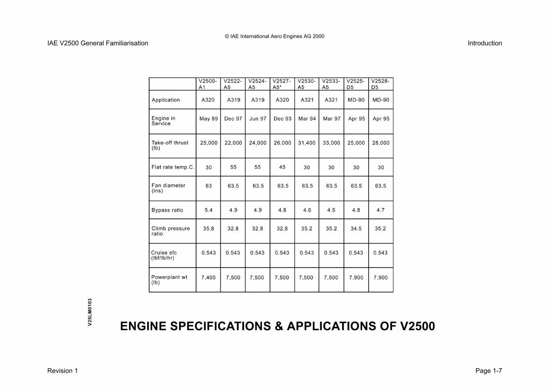
© IAE International Aero Engines AG 2000 IAE V2500 General Familiarisation Introduction IAE V2500 Engine/Airframe Applications The V2500 engine has been designated the ‘V’ because International Aero Engines (IAE) was originally a five-nation consortium. The ‘V’ is the Roman numeral for five. The 2500 numbering indicated the first engine type to be released into production. This engine was rated at 25000lbs of thrust. For ease of identification of the present and all future variants of the V2500, IAE has introduced an engine designation system.
• All engines possess the V2500 numbering as a generic name.
• The first three characters of the full designation are V25. This will identify all the engines in the family.
• The next two figures indicate the engines rated sea level takeoff thrust.
• The following letter shows the aircrafts manufacturer.
• The last figure represents the mechanical standard of the engine.
This system will provide a clear designation of a particular engine as well as a simple way of grouping by name engines with similar characteristics.
• The designation V2500-D collectively describes all applications for the Boeing McDonnell Douglas MD-90 aircraft.
• The V2500-A collectively describes all the applications for the Airbus Industries aircraft.
This is irrespective of engine thrust rating. The number given after the alpha indicates the mechanical standard of the engine. For example;
• V2527-A5. The only engine exempt from these idents is the current service engine, which is already certified to the designated V2500-A1. There is only one standard of this engine rating and is utilised on the Airbus A320 aircraft. Note: The D5 variant is now no longer in production, however the engine is still extensively overhauled and re-furbished.
Revision 1 Page 1-4

© IAE International Aero Engines AG 2000 IAE V2500 General Familiarisation Introduction
Revision 1 Page 1-5

© IAE International Aero Engines AG 2000 IAE V2500 General Familiarisation Introduction
THIS PAGE IS LEFT INTENTIONALLY BLANK
Revision 1 Page 1-6
© IAE International Aero Engines AG 2000 IAE V2500 General Familiarisation Introduction
Revision 1 Page 1-7

© IAE International Aero Engines AG 2000 IAE V2500 General Familiarisation Introduction Introduction to the Propulsion System The V2500 family of engines share a common design feature for the propulsion system. The complete propulsion system comprises the engine and the nacelle. The major components of the nacelle are as follows:
• The intake cowl.
• The fan cowl doors.
• Hinged ‘C’- ducts with integral thrust reverser units.
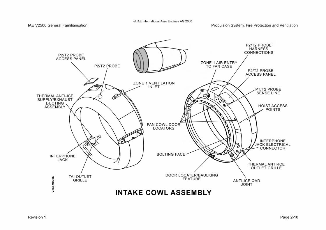
• Common nozzle assembly. Intake Cowl The ‘pitot’ style inlet cowl permits the efficient intake of air to the engine whilst minimising nacelle drag. The intake cowl contains the minimum of accessories. The two main accessories that are within the intake cowl are:
• P2/T2 probe.
• Thermal anti icing ducting and manifold. Fan Cowl Doors Access to the units mounted on the fan case and external gearbox can be gained easily by opening the hinged fan cowling doors. The fan cowl doors are hinged to the aircraft pylon in four positions. There are four quick release – adjustable latches that secure the fan cowl doors in the closed position.
Each fan cowl doors has two integral support struts that are secured to the fan case to hold the fan cowl doors in the open position. C - Duct Thrust Reverser units The ‘C’-ducts is hinged to the aircraft pylon at four positions per ‘C’-duct and is secured in the closed position by six latches located in five positions. The ‘C’-ducts is held in the open position by two integral support struts. Opening of the ‘C’-ducts allows access to the core engine. Common Nozzle Assembly (CNA) The CNA exhausts both the fan stream and core engine gas flow through a common propulsive nozzle.
Revision 1 Page 1-8

© IAE International Aero Engines AG 2000 IAE V2500 General Familiarisation Introduction
Revision 1 Page 1-9
© IAE International Aero Engines AG 2000 IAE V2500 General Familiarisation Introduction Engine The V2500 is a twin spool, axial flow, and high bypass ratio turbofan type engine. The engine incorporates several advanced technology features, which include: • Full Authority Digital Electronic Control (FADEC). • Wide chord fan blades. • Single crystal HP turbine blades. • 'Powdered Metal' HP turbine discs. • A two-piece, annular combustion system, which utilises
segmental liners. Engine Mechanical Arrangement The low-pressure (LP) system comprises a single stage fan and multiple stage booster. The booster, which is linked to the fan, has: • A5 standard four stages. • A1 standard three stages. The boosters are axial flow type compressors. A five-stage LP turbine drives the fan and booster. The booster stage has an additional feature. This is an annular bleed valve, which has been incorporated to improve starting and handling.
Three bearing assemblies support the LP system. They are: • A single ball type bearing (thrust). • Two roller type bearings (support). The HP system comprises of a ten-stage axial flow compressor, which is driven by a two-stage HP turbine. The HP compressor has variable inlet guide vanes (VIGV) and variable stator vanes (VSV).
• The A5 standard has one stage of VIGV and three stages of VSV’s.
• The A1 standard has one stage of VIGV and four stages of VSV's.
The HP system utilises four bleed air valves. These valves are designed to bleed air from the compressors so as to improve both starting and engine operation and handling characteristics. Two bearing assemblies support the HP system. They are:
• A single ball type bearing (thrust). • A single roller type bearing (support). The combustion system is of an annular design, constructed with an ‘inner’ and ‘outer’ section. There are twenty fuel spray nozzles supplying fuel to the combustor. The fuel is metered according to the setting of the thrust lever or the thrust management computer via the FADEC system.
Revision 1 Page 1-10

© IAE International Aero Engines AG 2000 IAE V2500 General Familiarisation Introduction
Revision 1 Page 1-11

IAE V2500 General Familiarisation Introduction
The FADEC system uses pressures and temperatures of the engine to control the various systems for satisfactory engine operation. The sampling areas are identified as stations and are common to all variants of the V2500 engine. The following are the measurement stations for the V2500 engine:
• Station 1 - Intake/Engine inlet interface.
• Station 2 - Fan inlet.
• Station 2.5 – LPC Outlet Guide Vane (OGV) exit.
• Station 12.5 - Fan exit/ C-Duct by-pass air.
• Station 3 - HP Compressor exit.
• Station 4.9 - LP Turbine exit. Engine stage numbering The V2500 engine has compressor blade numbering as follows: Stage 1 - Fan. Stage 1.5 - LPC booster Stage 2 - LPC booster. Stage 2.3 - LPC booster (A5 Only). Stage 2.5 - LPC booster. Stages (3-12) - HPC Stages. Note the HPC is a ten-stage compressor. The V2500 engine has turbine blade stage numbering as follows:
Stages (1-2) - HP Turbine Stages. Stages (3-7) - LP Turbine Stages. V2500-A1 V2527-A5
EIS May 89 Dec 93
Take-off thrust (lb) 25,000 26,500
Flat rate temp (°C) 30 45
Fan diameter (ins) 63 63.5
Airflow (lb/s) 792 811
Bypass ratio 5.4 4.8
Climb-pressure ratio 35.8 32.8
Cruise sf (lbf/lb/hr) 0.543 0.543
Power plant wt. (lb) 7400 7500
Revision 1 Page 1-12

IAE V2500 General Familiarisation Introduction
Revision 1 Page 1-13


SECTION 2
PROPULSION SYSTEM, FIRE PROTECTION &
VENTILATION

© IAE International Aero Engines AG 2000 IAE V2500 General Familiarisation Propulsion System, Fire Protection and Ventilation Propulsion System Introduction Purpose The propulsion system encloses the Powerplant. They provide the ducting for the fan bypass air and provide for an aerodynamic exterior. Description The propulsion system comprises of the engine and the following nacelle units:
• Intake cowl assembly.
• The L and R hand hinged fan cowl doors.
• The thrust reverser C-ducts.
• The common nozzle assembly (CNA).
• Engine mounts for the front and rear of the engine.
• Fire protection and ventilation system.
Revision 1 Page 2-1

© IAE International Aero Engines AG 2000 IAE V2500 General Familiarisation Propulsion System, Fire Protection and Ventilation
Revision 1 Page 2-2

© IAE International Aero Engines AG 2000 IAE V2500 General Familiarisation Propulsion System, Fire Protection and Ventilation Airframe Interfaces Purpose The airframe interfaces provide a link between the engine and aircraft systems. Description The following units form the interface between the aircraft and engine:
• The front and rear engine mounts.
• The bleed air off-takes.
• The starter motor air supply.
• Integrated Drive Generator (IDG) electrical power.
• Fuel supplies.
• Hydraulic fluid supplies.
• FADEC system interfaces.
Revision 1 Page 2-3

© IAE International Aero Engines AG 2000 IAE V2500 General Familiarisation Propulsion System, Fire Protection and Ventilation
Revision 1 Page 2-4

© IAE International Aero Engines AG 2000 IAE V2500 General Familiarisation Propulsion System, Fire Protection and Ventilation Propulsion System Access Panels Purpose The propulsion system access panels provide the engineer with quick access to the components that require regular or scheduled inspection. The access panels allow the removal and installation of Line Replaceable Units (LRU’s) during maintenance activities. Description The access panels provided on the propulsion system are as follows: Engine Left Hand Side Fan cowl door Oil tank service door. Master magnetic chip detector panel. Zone 1 Ventilation Outlet Grille for the Fan Case. Thrust reverser C-duct Maintenance access panels for the thrust reverser hydraulic actuators. Translating cowl lockout pins.
Engine Right Hand Side Intake cowl Interphone jack. Anti icing outlet grille. P2/T2 probe access panel. Fan cowl doors Air-cooled oil cooler outlet. Starter motor air valve access panel. Zone 1 Ventilation Outlet Grille for the Fan Case. Breathers overboard discharge. Thrust reverser C duct Maintenance access panels for the thrust reverser hydraulic actuators. Translating cowl lockout pins.
Revision 1 Page 2-5

© IAE International Aero Engines AG 2000 IAE V2500 General Familiarisation Propulsion System, Fire Protection and Ventilation
Revision 1 Page 2-6

© IAE International Aero Engines AG 2000 IAE V2500 General Familiarisation Propulsion System, Fire Protection and Ventilation Propulsion System Core Engine Access Purpose The propulsion system can be opened to allow access for engineers both to the fan case and core engine. Description Fan cowl doors The fan cowl doors are hinged from the aircraft strut at the top and are secured by four latches at the bottom. When in the open position they are supported by two support struts per Fan Cowl. Thrust reverser C ducts The Thrust Reverser C-ducts are hinged from the aircraft strut at the top by four hinged type brackets and are secured by six latches at the bottom. When in the open position they are supported by two support struts per C-duct.
Propulsion System Materials and Weights Intake cowl The intake cowl is made up of the following materials:
• Intake D section is aluminium.
• Intake cowl is carbon fibre.
• Intake cowl weight is 238 lbs. (107.98 Kg). Fan cowl doors The fan cowl doors are made up of the following materials:
• Carbon fibre and aluminium.
• LH fan cowl door weight is 79 lbs. (35.84 Kg).
• RH fan cowl door weight is 86 lbs. (39.01 Kg). Thrust Reverser C-ducts The thrust reverser C ducts are made up of the following materials:
• C-duct structure and translating cowls are carbon fibre and aluminium.
• The thrust reverser C-duct weight is 578 lbs. (262.25 Kg).
Common nozzle assembly (CNA) The CNA is made up of the following material:
• Titanium.
• CAN weight is 213 lbs.
Revision 1 Page 2-7

© IAE International Aero Engines AG 2000 IAE V2500 General Familiarisation Propulsion System, Fire Protection and Ventilation
Revision 1 Page 2-8

© IAE International Aero Engines AG 2000 IAE V2500 General Familiarisation Propulsion System, Fire Protection and Ventilation Intake Cowl Purpose To supply all the air required by the engine, with minimum pressure losses and with an even pressure face to the fan. Nacelle drag is also minimised due to the aerodynamically streamlined design. Location The inlet cowl is bolted to the front of the LPC case (Fan). Description The intake cowl is constructed from hollow inner and outer skins. These are supported by front (titanium) and rear (Graphite/Epoxy composite) bulkheads. Inner and outer skins are manufactured from composites. The leading edge is a 'one piece' pressing in Aluminium. The cowl weight is approximately 238 lbs. The intake cowl has the following features:
• Integral thermal anti-icing system.
• P2T2 Probe.
• Ventilation Intake.
• Interphone socket.
• Engine attachment ring with alignment pins to ensure correct location of the cowl on to the fan case.
• Door locators that automatically align the fan cowl doors to ensure good sealing.
• Strut brackets to provide location for the left and right hand fan cowl door support struts (front struts only).
Revision 1 Page 2-9
© IAE International Aero Engines AG 2000 IAE V2500 General Familiarisation Propulsion System, Fire Protection and Ventilation
Revision 1 Page 2-10

© IAE International Aero Engines AG 2000 IAE V2500 General Familiarisation Propulsion System, Fire Protection and Ventilation Fan Cowl Doors (FCD) Purpose The fan cowl doors provide for an aerosmooth exterior while enclosing the fan case mounted accessories. Location They are located about the fan casing. Hinged at the top to the aircraft strut and secured by four latches at the bottom. Description The doors extend rearwards from the inlet cowl to overlap leading edge of the 'C' ducts. The A320 aircraft have a strake on the inboard cowl of each engine, the right hand cowl on both engine 1 and left-hand cowl on engine 2. The A319 aircraft have strakes on both the left-hand and right hand cowls on both engines 1 and 2. Fan cowls are interchangeable between the A319 and A320 except for the strake configuration. Make sure the correct configuration is installed. The fan cowl doors are constructed from graphite skins enclosing an aluminium honeycomb inner. Aluminium is also used to reinforcement each corner to minimises handling/impact damage and wear. The fan cowl doors abut along the bottom centre line and are secured to each other by 4 quick release and adjustable latches.
Revision 1 Page 2-11

© IAE International Aero Engines AG 2000 IAE V2500 General Familiarisation Propulsion System, Fire Protection and Ventilation
Revision 1 Page 2-12

© IAE International Aero Engines AG 2000 IAE V2500 General Familiarisation Propulsion System, Fire Protection and Ventilation Thrust Reverser C Ducts Purpose The thrust reverser C ducts provide for: • An aerosmooth exterior to minimise drag. • The fan bypass ducting. • Reverse thrust for aircraft deceleration. Location The thrust reverser C ducts are hinged from the aircraft strut at the top and are secured at the bottom by six toggle type clamps. Description The thrust reverser C ducts extend rearwards from the fan cowls to the common nozzle assembly (CNA). The thrust reverser C ducts; Form the cowling around the core engine (inner barrel) to assist in stiffening the core engine (load-share). Form the fan air duct between the fan case exit and the entrance to the CNA. House the thrust reverser operating mechanism and cascades. Form the outer cowling between the fan cowl doors and CNA. The thrust reverser C ducts are mostly constructed from composites but some sections are metallic mainly aluminium for example the inner barrel, blocker doors and links.
The thrust reverser C-ducts can be opened for access to the core engine. This allows maintenance to be carried out on the core engine while the engine is installed to the aircraft. The thrust reverser C-ducts are heavy therefor hydraulic actuation is required to open them. Normal engine oil is used in a hand-operated pump. The thrust reverser C-ducts are held in the open position by two support struts.
• The forward strut is a fixed length.
• The rear strut is a telescopic support.
•
Revision 1 Page 2-13

© IAE International Aero Engines AG 2000 IAE V2500 General Familiarisation Propulsion System, Fire Protection and Ventilation
Revision 1 Page 2-14

© IAE International Aero Engines AG 2000 IAE V2500 General Familiarisation Propulsion System, Fire Protection and Ventilation Combined Nozzle Assembly (CNA) Purpose The CNA allows the mixing of the hot and cold stream gas flows to produce the resultant thrust. Location The CNA is bolted to the rear flange of the turbine exhaust casing. There is no fixing to the bottom of the pylon. Description The CNA: Forms the exhaust unit.
• Mixes the hot and cold gas streams and ejects the combined flow to atmosphere through a single propelling nozzle.
• Completes the engine nacelle.
Revision 1 Page 2-15

© IAE International Aero Engines AG 2000 IAE V2500 General Familiarisation Propulsion System, Fire Protection and Ventilation
Revision 1 Page 2-16

© IAE International Aero Engines AG 2000 IAE V2500 General Familiarisation Propulsion System, Fire Protection and Ventilation Engine Mounts Purpose The engine mounts suspend the engine from the aircraft strut. The engine mounts transmit loads generated by the engine during aircraft operation. Location The front engine mount is located at the rear of the intermediate case at the core engine. The rear engine mount is located on the LPT casing at TDC. Description Forward engine mount The forward engine mount is designed to transmit the following loads: • Thrust loads. • Side loads. • Vertical loads. The front mount is secured to the intermediate case in three positions: A monoball type universal joint. This gives the main support at the front engine mount position. Two thrust links that are attached to: • The cross beam of the engine mount. • Support brackets either side of the monoball location.
Rear engine mount The rear engine mount is designed to transmit the following loads: • Torsional loads. • Side loads. • Vertical loads. The rear engine mount has a diagonal main link that gives resistance to torsional movement of the casing as a result of the hot gas passing through the turbines. There is further support from two side links. These limit the engine side to side movement and give vertical support.
Revision 1 Page 2-17

© IAE International Aero Engines AG 2000 IAE V2500 General Familiarisation Propulsion System, Fire Protection and Ventilation
Revision 1 Page 2-18

THIS PAGE IS LEFT INTENTIONALLY BLANK

FIRE PROTECTION AND VENTILATION

© IAE International Aero Engines AG 2000 IAE V2500 General Familiarisation Propulsion System, Fire Protection and Ventilation Fire Protection and Ventilation Purpose The purpose of fire protection is to give an indication to the flight deck of a possible fire condition about the engine. The purpose of the ventilation system is to provide a flow of cooling air about the engine to reduce the risk of a fire condition annunciation to the flight deck. Location The locations of the fire detection fire wires are about the fan casing and core engine. The location of the ventilation air is about the entire of the fan case and core engine. Description The engine is ventilated to provide a cooling airflow for maintaining the engine components within an acceptable operating temperature. Also to provide a flow of air that assists in the removal of potential combustible liquids that may be in the area. Ventilation is provided for:
• The fan case area (Zone 1).
• The core engine area (Zone 2). Zones 1 and 2 are ventilated to:
• Prevent accessory and component over heating.
• Prevent the accumulation of flammable vapours.
Zone 1 ventilation Ram air enters the zone through an inlet located on the upper LH side of the air intake cowl. The air circulates through the fan compartment and exits at the exhaust located on the bottom rear centre line of the fan cowl doors. Zone 2 ventilation Metered holes within the inner barrel of the “C” duct allow pressurized fan air to enter the zone 2 area. Air exhausting from the active clearance control (ACC) system around the turbine area also provides ventilation air for Zone 2. The air circulates through the core compartment and exits through the lower bifurcation of the C ducts via the thrust recovery duct. Ventilation during ground running During ground running local pockets of natural convection exist providing some ventilation of the fancase zone 1. Zone 2 ventilation is provided by the fan duct pressure as above during ground running and in flight.
Revision 1 Page 2-19

© IAE International Aero Engines AG 2000 IAE V2500 General Familiarisation Propulsion System, Fire Protection and Ventilation
Revision 1 Page 2-20

© IAE International Aero Engines AG 2000 IAE V2500 General Familiarisation Propulsion System, Fire Protection and Ventilation Fire Detection System Purpose The fire detection system monitors the air temperature in Zone 1 and Zone 2. When the air temperature increases to a pre determined level the system provides flight deck warning. Location The fire detection system is located:
• Routed around the high-speed external gearbox.
• At BDC of the core engine nearest to the combustor diffuser case.
Description The V2500 utilises a Systron Donner fire detection system. It has a gas filled core and relies upon heat exposure to increase the internal gas pressure. Thus triggering sensors. When the air temperature about the fan case and/or core engine increases to a pre-determined level the system is designed to detect this and display a warning message and indications to the flight deck. The system provides flight deck warning by:
• Master warning light.
• Audible warning tone.
• Specific ECAM fire indications.
• Engine fire push button illuminates.
Zone 1 and Zone 2 fire detectors function independently of each other. Each zone has two detector units which are mounted as a pair, each unit gives an output signal when a fire or overheat condition occurs. The two detector units are attached to support tubes by clips. Nacelle air temperature (NAC) Zone 2 has the nacelle air temperature sensor. Indication is to the flight deck when a temperature exceedance has occurred.
Revision 1 Page 2-21

© IAE International Aero Engines AG 2000 IAE V2500 General Familiarisation Propulsion System, Fire Protection and Ventilation
Revision 1 Page 2-22

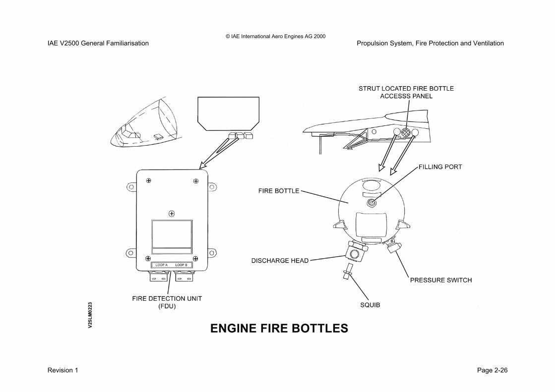
© IAE International Aero Engines AG 2000 IAE V2500 General Familiarisation Propulsion System, Fire Protection and Ventilation Fire Detection System and Detector Units The fire detection system employs detector units called firewires. The firewires are mounted in pairs. This is necessary due to the class1 level 3 message that they generate when a fire or overheat condition exists. The fire detection system comprises of the following units: • The firewires send a signal to the Fire Detection Unit
(FDU). • The FDU sends a signal to the Flight Warning
Computer (FWC). • The FWC generates the flight deck indications for a fire
condition. There is one FDU per engine. The FDU has two channels; each channel is looking at a separate fire detector loop of zones 1 and 2. Under normal conditions both firewires require to be indicating to the FDU to give a real indication to the flight deck. If there is a single loop failure of more than 16 seconds then the remaining firewire will continue to operate. The FDU will recognise the faulty fire loop. The faulty loop will be indicated to ECAM as the following message: ENG 1 (2) FIRE LOOP A (B) FAULT If there is a double loop failure then the FDU will recognise this as a possible burn through and the fire message will be generated to the flight deck.
Firewire detectors Each of the fire wire detector units comprises of the following: • A hollow sensor tube. • A responder assembly. Sensor tube The sensor tube is closed and sealed at one end and the other open end is connected to the responder. The tube is filled with helium gas and carries a central core of ceramic material impregnated with hydrogen. An increase in the air temperature around the sensor tube causes the helium to expand and increase until the pressure causes the alarm switch to close. The FDU recognises this as an abnormal situation, hence fire indication will be illuminated. If a ‘burn through’ occurs, the pressure within the sensing tube is lost and as a result of this the integrity switch opens to give an indication to the FDU of a loop failure. Responder The responder has two pressure switches, one normally open and the other normally closed. • The normally open switch is the alarm indication. • The normally closed switch is the fault indication.
Revision 1 Page 2-23

© IAE International Aero Engines AG 2000 IAE V2500 General Familiarisation Propulsion System, Fire Protection and Ventilation
Revision 1 Page 2-24

© IAE International Aero Engines AG 2000 IAE V2500 General Familiarisation Propulsion System, Fire Protection and Ventilation Fire Detection System Fire Bottles Purpose The fire bottles provide a means of extinguishing a potentially hazardous fire about the engine when a fire annunciation to the flight deck has occurred. Location The engine fire bottles are located in the aircraft strut. Access for maintenance is via a panel that can be found on the left hand side. Description The fire bottles have the following features:
• Agent type is bromotrifluoromethane.
• Charged to a nominal pressure of 600 psi at 21 deg. C.
• Pressure switch.
• Discharge head.
• Discharge squibs. The pressure switch is set to indicate bottle empty when the pressure falls below 225 psi. The indication in the flight deck is: AGENT 1 (2) SQUIB DISC This is an illuminating annunciator light on the overhead panel.
The discharge head has a leak proof diaphragm that is designed to rupture when:
• The squib is activated from the flight deck.
• Excessive pressure in the fire bottle. 1600 to 1800 psi at 95 deg. C
The squib is an Electro Pyrotechnic Cartridge containing explosive powder. Two filaments ignite the powder when they are supplied with 28v dc. There is facility to carry out a fire system test that will give all the expected indications if all is functioning correctly. The fire test switch is located on the fire push button panel on the overhead panel.
Revision 1 Page 2-25
© IAE International Aero Engines AG 2000 IAE V2500 General Familiarisation Propulsion System, Fire Protection and Ventilation
Revision 1 Page 2-26

© IAE International Aero Engines AG 2000 IAE V2500 General Familiarisation Propulsion System, Fire Protection and Ventilation Fire Detection System Indications and Controls Purpose The purpose of the fire detection system indications is to alert the flight crew to a possible fire condition. The controls allow the flight crew to react and deal with the impending fire indication in the flight deck. Location The fire control panel is located on the overhead panel for fire bottle operation and fire system test.
Revision 1 Page 2-27

© IAE International Aero Engines AG 2000 IAE V2500 General Familiarisation Propulsion System, Fire Protection and Ventilation
Revision 1 Page 2-28

© IAE International Aero Engines AG 2000 IAE V2500 General Familiarisation Propulsion System, Fire Protection and Ventilation Nacelle Air Temperature (NAC) Purpose The nacelle air temperature gives an advisory indication to the lower ECAM CRT if a temperature exceedance has been experienced. Location The NAC sensor is located by the bifurcation panel at bottom dead centre between the two-thrust reverser C duct halves. The NAC is in zone 2. Description Under normal conditions the NAC indication is not displayed on the lower ECAM CRT. When a temperature exceedance of 320 deg.c has occurred the indication will appear to the lower ECAM CRT. This indication is displayed if; The system is not in engine starting mode and one of the two temperatures reaches the advisory threshold.
Revision 1 Page 2-29

© IAE International Aero Engines AG 2000 IAE V2500 General Familiarisation Propulsion System, Fire Protection and Ventilation
Revision 1 Page 2-30


SECTION 3
MECHANICAL ARRANGEMENT

© IAE International Aero Engines AG 2000 IAE V2500 General Familiarisation Mechanical Arrangement Mechanical Arrangement General The engine is an axial flow, high by-pass ratio, twin spool turbo fan. The general arrangement is shown below. L.P. System Four stage L.P. compressor - comprising:
• 1 Fan stage
• L.P. Compressor consisting of 4 stages driven by:
• Five stage L.P. Turbine H.P. System • Ten-stage axial flow compressor driven by a 2 stage
H.P. Turbine.
• Variable angle inlet guide vanes.
• Variable stator vanes (3 stages A5).
• Handling bleed valves at stage 7 and 10. Customer service bleeds at stage 7 and 10 Combustion System
• Annular, two piece, with 20 fuel spray nozzles. Gearbox
• Radial drive via a tower shaft from H.P. Compressor shaft to fan case mounted Angle and Main gearboxes.
Gearbox provides mountings and drive for all engine driven accessories and the pneumatic starter motor.
Revision 1 Page 3-1

© IAE International Aero Engines AG 2000 IAE V2500 General Familiarisation Mechanical Arrangement
Revision 1 Page 3-2

© IAE International Aero Engines AG 2000 IAE V2500 General Familiarisation Mechanical Arrangement Engine Main Bearings The main bearing arrangement and the bearing numbering system is shown below. The 5 bearings are located in 3 bearing compartments: • The Front Bearing Compartment, located at the centre of the Intermediate Case, houses No's 1,2 & 3 bearings. • The Centre Bearing Compartment located in the diffuser/combustor case houses No 4 Bearing. • The Rear Bearing Compartment located in the Turbine Exhaust Case houses No 5 Bearing. No 1 Bearing • Shaft axial location bearing. • Takes the thrust loads of the L.P. shaft. • Single track ball bearing. No 2 Bearing • Radial support for the front of the L.P.turbine shaft. Single track roller bearing utilising "squeeze film" oil damping. • No 3 Bearing • H.P. shaft axial location bearing. • Radial support for the front of the H.P.shaft. • Takes the thrust loads of the H.P. shaft. • Single track ball bearing. • Mounted in a hydraulic damper, which is centred by a series of rod springs (squirrel cage).
No 4 Bearing • Radial support for turbine end of H.P. shaft. • Single track roller bearing. No 5 Bearing • Radial support for the turbine end of the L.P. shaft. • Single track roller bearing. Squeeze film oil damping.
Revision 1 Page 3-3

© IAE International Aero Engines AG 2000 IAE V2500 General Familiarisation Mechanical Arrangement
Revision 1 Page 3-4

© IAE International Aero Engines AG 2000 IAE V2500 General Familiarisation Mechanical Arrangement Engine Internal Cooling and Sealing Airflows Purpose To provide sealing air for the bearing chambers so as to prevent oil loss. To provide cooling air for the engines internal components keeping them within designed operating temperatures. Location The air used for internal cooling and sealing is taken from the compressor stages of:
• LPC stage 2.5 • HPC stage 8. • HPC stage 10. • HPC stage 12. • The fan bypass provides external cooling air.
Description Fan air is used to provide:
• Air for the Active Clearance Control (ACC) system. This is used to control the tip clearances of the turbine blades.
• Air through the Air Cooled Air Cooler (ACAC). This is used for the precooling of the ‘buffer air’.
Buffer air is used to provide:
• Cooling, sealing and scavenge air for the No.4 Bearing Chamber.
LPC stage 2.5 air is used for
• Sealing of the front and rear of the Front Bearing Chamber
HPC stage 7 air is used for airflow control for compressor stability and aircraft services bleed supply. HPC stage 8 is used for:
• Sealing the hydraulic seal of the Front Bearing Chamber and the sealing of the No. 5 Bearing Chamber.
HPC stage 10 air is used for:
• Airflow control and aircraft services supply. • ‘Make up’ air supply for the HPT stage 2 disc and
blades. • Cooling air for the HPT stage 2 NGVs.
HPC stage 12 air is used for:
• Combustion chamber cooling. • HPT stage 1 blades and NGVs cooling. • The supply to the ACAC for buffer air cooling and
sealing of the no. 4 bearing chamber.
Revision 1 Page 3-5

© IAE International Aero Engines AG 2000 IAE V2500 General Familiarisation Mechanical Arrangement
Revision 1 Page 3-6
© IAE International Aero Engines AG 2000 IAE V2500 General Familiarisation Mechanical Arrangement Modular Construction Modular construction has the following advantages:
• lower overall maintenance costs
• maximum life achieved from each module
• reduced turn-around time for engine repair
• reduced spare engine holdings
• ease of transportation and storage
• rapid module change with minimum ground running
• easy hot section inspection
• vertical/horizontal build strip
• split engine transportation
• compressors/turbines independently balanced Module Designation Module No Module 31 Fan 32 Intermediate 40 HP System
− 41 - HP Compressor
− 45 - HP Turbine 50 LP Turbine 60 External gearbox
Note: The module numbers refer to the ATA chapter reference for that module.
Revision 1 Page 3-7

© IAE International Aero Engines AG 2000 IAE V2500 General Familiarisation Mechanical Arrangement
Revision 1 Page 3-8

© IAE International Aero Engines AG 2000 IAE V2500 General Familiarisation Mechanical Arrangement Module 31 Description Module 31 (Fan Module) is the complete Fan assembly and comprises:
• 22 Hollow fan blades
• 22 Annulus Fillers
• Fan Disc
• Front and Rear Blade Retaining Rings The blades are retained in the disc radially by the dovetail root. The front and rear blade retaining rings provides axial retention. Blade removal/replacement is easily achieved by removing the front blade retaining ring and sliding the blade along the dovetail slot in the disc. 22 annulus fillers form the fan inner annulus. The nose cone and fairing smooth the airflow into the fan.
Revision 1 Page 3-9

© IAE International Aero Engines AG 2000 IAE V2500 General Familiarisation Mechanical Arrangement
Revision 1 Page 3-10

© IAE International Aero Engines AG 2000 IAE V2500 General Familiarisation Mechanical Arrangement Module 32 - Intermediate Case The Intermediate Module comprises of:
• Fan Case
• Fan Duct
• Fan Outlet Guide Vanes (OGV)
• LP Compressor ( A5 - 4 stage)
• LP Compressor Bleed Valve (LPCBV)
• Front engine mount structure
• Front bearing compartment which houses Nos. 1, 2 and 3 bearings
• Drive gear for the power off-take shaft (gearbox drive)
• LP stub shaft
• Inner support struts
• Outer support struts
• Vee groove locations for the inner and outer barrels of the 'C' ducts
Revision 1 Page 3-11

© IAE International Aero Engines AG 2000 IAE V2500 General Familiarisation Mechanical Arrangement
Revision 1 Page 3-12

© IAE International Aero Engines AG 2000 IAE V2500 General Familiarisation Mechanical Arrangement Module 32 - Intermediate Case Instrumentation The following pressures and temperatures are sensed and transmitted to the E.E.C.
• P12.5
• P2.5
• T2.5 The rear view of the intermediate case is shown below.
Revision 1 Page 3-13

© IAE International Aero Engines AG 2000 IAE V2500 General Familiarisation Mechanical Arrangement
Revision 1 Page 3-14

© IAE International Aero Engines AG 2000 IAE V2500 General Familiarisation Mechanical Arrangement Module 40 HP Compressor Description The HP compressor assembly (Module 40 is a 10 stage axial flow compressor. It has a rotor assembly and stator case. The compressor stages are numbered from the front, with the first stage is stage being designated as stage 3 of the whole engines compressor system. Airflow through the compressor is controlled by variable inlet guide vanes (VIGV), variable stator vanes (VSV) and bleed valves. The rotor assembly has five sub-assemblies (1) Stages 3 to 8 HP compressor disks (2) A vortex reducer ring. (3) Stages 9 to 12 HP compressor disks (4) The HP compressor shaft. (5) The HP compressor rotating air seal. The five sub-assemblies are bolted together to make the rotor. The compressor blades in stages 3 to 5 are attached to the compressor disks in axial dovetail slots and secured by lockplates. The stages 6 to 12 compressor blades are installed in slots around the circumference of the disks through an axial loading slot. Lock blades, lock nuts and jack screws hold the blades in position. The HP compressor stator case has two primary sub-assemblies, the HP compressor front and rear cases.
Revision 1 Page 3-15

© IAE International Aero Engines AG 2000 IAE V2500 General Familiarisation Mechanical Arrangement
Revision 1 Page 3-16

© IAE International Aero Engines AG 2000 IAE V2500 General Familiarisation Mechanical Arrangement Module 40 HP Compressor The HP compressor front case assembly has two split cases bolted together along the engine horizontal centre line. The front case assembly contains the VIGV’s, the stages 3 to 5 VSV’s and the stage 6 stator vanes. The front outer case provides a mounting for the VIGV and VSV actuator. The front case assembly is bolted to the intermediate case and to the rear outer case. The HP compressor rear case assembly has five inner ring cases and an outer case. Flanges on the inner cases form annular manifolds, which provide stages 7 and 10 air offtakes. The five inner cases are bolted together, with the front support cone bolted at the stage 7 case and the stage 11 case bolted to the rear outer case. The five inner cases contain the stages 7 to 11 fixed stator vanes. The rear outer case is bolted to the diffuser case and to the rear flange of the HP compressor front case. Access is provided in the compressor cases for borescope inspection of the compressor blades and stator vanes
Revision 1 Page 3-17

© IAE International Aero Engines AG 2000 IAE V2500 General Familiarisation Mechanical Arrangement
Revision 1 Page 3-18

© IAE International Aero Engines AG 2000 IAE V2500 General Familiarisation Mechanical Arrangement Combustion Section The combustion section includes the diffuser section, the combustion inner and outer liners, and the No 4 bearing assembly. Diffuser Casing The diffuser section is the primary structural part of the combustion section. The diffuser section has 20 mounting pads for the installation of the fuel spray nozzles. It also has two mounting pads for the two ignitor plugs. Combustion Liner The inner and outer liners form the combustion liner. The outer liner is located by five locating pins, which pass through the diffuser casing. The inner combustion liner is attached to the turbine nozzle guide vane assembly. The inner and outer liners are manufactured from sheet metal with 100 separate liner segments attached to the inner surface (50 per inner and outer liner). The segments can be replaced independently during engine overhaul.
Revision 1 Page 3-19

© IAE International Aero Engines AG 2000 IAE V2500 General Familiarisation Mechanical Arrangement
Revision 1 Page 3-20

© IAE International Aero Engines AG 2000 IAE V2500 General Familiarisation Mechanical Arrangement HP Turbine Description The primary parts of the HP turbine rotor and stator assembly are: The HP Turbine Rotor Assemblies (Stage 1 and Stage 2) The HP Turbine Case and Vane Assembly The HP turbine rotor assemblies are two stages of turbine hubs with single-crystal, nickel-alloy blades. The two-hub configuration removes a bolt flange between hubs. This decreases the weight and enables faster engine assembly. The blades have airfoils with high strength and resistance to creep. Satisfactory blade tip clearances are supplied by active clearance control (ACC) to cool the case with compressor air.
Revision 1 Page 3-21

© IAE International Aero Engines AG 2000 IAE V2500 General Familiarisation Mechanical Arrangement
Revision 1 Page 3-22

© IAE International Aero Engines AG 2000 IAE V2500 General Familiarisation Mechanical Arrangement LP Turbine Description The primary parts of the Low Pressure Turbine (LPT) module are:
• LPT Five Stage Rotor
• LPT Five Stage Stator Vanes
• Air Seals
• LPT Case
• Inner and Outer Duct
• LPT Shaft
• Turbine Exhaust Case (TEC) The LP turbine has a five stage rotor which supplies power to the LP compressor through the LPT shaft. The LPT rotor is installed in the LPT case where it is in alignment with the LPT stators. The LPT case is made from high-heat resistant nickel alloy and is a one part welded assembly. To identify the LP turbine module, an identification plate is attached to the LP turbine case at the 136degrees position. The LPT case has two borescope inspection ports at 125.27 and 237.10 degrees. The ports are used to internally examine the adjacent engine sections:
• Trailing Edge (TE), Stage 2, HPT Blades
• Leading Edge (LE), Stage 3, LPT Blades
• Trailing Edge (TE), Stage 3, LPT Blades
The five LPT disks are made from high heat resistant nickel alloy. The LPT blades are also made from nickel alloy and are attached to the disks by fir-tree roots. The blades are held in axial position on the disk by the rotating air seals (knife-edge).
Revision 1 Page 3-23

© IAE International Aero Engines AG 2000 IAE V2500 General Familiarisation Mechanical Arrangement
Revision 1 Page 3-24

© IAE International Aero Engines AG 2000 IAE V2500 General Familiarisation Mechanical Arrangement Module 60 - External Gearbox Purpose The gearbox assembly transmits power from the engine to provide drives for the accessories mounted on the gearbox front and rear faces. During engine starting the gearbox also transmits power from the pneumatic starter motor to the core engine. The gearbox also provides a means of hand cranking the HP rotor for maintenance operations. Location The gearbox is mounted by 4 flexible links to the bottom of the fan case.
• Main gearbox 3 links.
• Angle gearbox 1 link. Description The external gearbox is a cast aluminium housing that has the following features;
• Individually replaceable drive units.
• Magnetic chip detectors.
• Main gearbox 2 magnetic chip detectors.
• Angle gearbox 1 magnetic chip detector.
The following accessory units are located on the external gearbox; Front Face Mount Pads • De-oiler.
• Pneumatic starter.
• Dedicated generator.
• Hydraulic Pump.
• Oil Pressure pump and filter. Rear Face Mount Pads
• Fuel pumps (and fuel metering unit FMU).
• Oil scavenge pumps unit.
• Integrated drive generator (IDG). The Oil sealing for the gearbox to accessory drive links is provided by a combination of carbon and ‘O’-ring type seals. The carbon seals can be replaced while the engine is on wing.
Revision 1 Page 3-25

© IAE International Aero Engines AG 2000 IAE V2500 General Familiarisation Mechanical Arrangement
Revision 1 Page 3-26

© IAE International Aero Engines AG 2000 IAE V2500 General Familiarisation Mechanical Arrangement Engine View Right Hand Side The following components are located on the right hand side of the engine. 1. Stage 10 make-up air valve for supplementary turbine
cooling. 2. IDG harness interface. 3. Harness interface. 4. Start air and anti ice ducting interface. 5. Electrical harness interface. 6. Air starter duct. 7. Engine electronic control. 8. Anti ice duct. 9. Relay box. 10. Anti ice valve. 11. Starter valve. 12. 10th stage handling bleed valve solenoid. 13. No.4 bearing scavenge valve. 14. Air-cooled oil cooler (ACOC). 15. Intergrated drive generator (IDG). 16. Exciter ignition boxes. 17. Fuel distribution valve. 18. HPC stage 7B handling bleed valve.
19. LPT and HPT active clearance control valves (ACC). 20. HPC stage 10 handling bleed valve. 21. Engine rear mount. 22. Booster bleed valve slave actuator. 23. Front engine mount. 24. HPC 10th stage cooling air for the HPT 2nd stage NGVs. 25. Solenoids for the three off HPC 7th stage handling
bleed valves. 26. Solenoid for the HP10 make-up cooling air control
valve. 27. Solenoid for the HP10 cabin bleed pressure
regulating/shut-off valve (PRSOV).
Revision 1 Page 3-27

© IAE International Aero Engines AG 2000 IAE V2500 General Familiarisation Mechanical Arrangement
Revision 1 Page 3-28

© IAE International Aero Engines AG 2000 IAE V2500 General Familiarisation Mechanical Arrangement Engine View Left Hand Side The following components are located on the left-hand side of the engine. 1. Fan cowl door hinged brackets (4 off). 2. Thrust reverser hydraulic control valve (HCU). 3. Hydraulic tubes interface. 4. Fuel supply and return to wing tank. 5. C duct front hinge. 6. Thrust reverser hydraulic tubes interface. 7. Over pressuerization valve (OPV). 8. 2.5 bleed master actuator. 9. C Duct floating hinges. 10. Fan Air Valve (FAV). 11. C Duct rear hinge. 12. Opening actuator mounting brackets. 13. C Duct compression struts (3off). 14. Cabin bleed air pre cooler duct interface. 15. Cabin bleed air system interface. 16. Pressure regulating valve (PRV). 17. Air-cooled air cooler (ACAC). 18. HPC 10th stage cabin bleed offtake pipe. 19. HPC 10th stage pressure regulating/shut-off valve
(PRSOV).
20. HPC 7th stage bleed valve (HPC7 C). 21. HPC 7th stage cabin bleed non-return valve (NRV). 22. VIGV/VSV actuator. 23. Fuel pumps and fuel metering unit. 24. High speed external gearbox. 25. Hydraulic pump. 26. Engine oil tank. 27. IDG oil cooler. 28. LP fuel filter. 29. Fuel cooled oil cooler (FCOC). 30. Savenge oil filter pressure differential switch. 31. Fuel return to tank valve (part of item 32). 32. Fuel diverter valve (part of item 31). 33. Oil pressure differential transmitter. 34. Low oil pressure switch.
Revision 1 Page 3-29

© IAE International Aero Engines AG 2000 IAE V2500 General Familiarisation Mechanical Arrangement
Revision 1 Page 3-30

© IAE International Aero Engines AG 2000 IAE V2500 General Familiarisation Mechanical Arrangement Engine Combined Drains System Purpose To provide an early indication of a system or component failure by evidence of a fluid leak. Location The drains systems of tubes are located about the engine. The drains mast is located at BDC of the fan case. It protrudes from the bottom of the fan cowl doors. Description This provides a combined overboard drain through a drains mast. The drains are for fuel and oil from the core module components, the LP compressor/intermediate case components and the external gearbox.
Revision 1 Page 3-31

© IAE International Aero Engines AG 2000 IAE V2500 General Familiarisation Mechanical Arrangement
Revision 1 Page 3-32


SECTION 4
ELECTRONIC ENGINE CONTROL

© IAE International Aero Engines AG 2000 IAE V2500 General Familiarisation Electronic Engine Control Electronic Engine Control Introduction The V2500 uses a Full Authority Digital Electronic Engine Control (FADEC). The FADEC comprises the sensors and data input, the electronic engine control unit (EEC) and the output devices, which include solenoids, fuel servo operated actuators and pneumatic servo operated devices. The FADEC also includes electrical harnesses. Engine Electronic Control The heart of the FADEC is the Engine Electronic Control (EEC) unit - shown below. The EEC is a fan case mounted unit, which is shielded and grounded as protection against EMI - mainly lightning strikes. Features
• Vibration isolation mountings.
• Shielded and grounded (lightning strike protection).
• Size - 15.9 X 20.1 X 4.4 inches.
• Weight - 41 lbs.
• Two independent electronic channels.
• Two independent power supplies, the EEC utilises 67.53 Watts of power from either the three phase AC from a dedicated engine mounted alternator, or 28 Volts DC from an aircraft source.
• A two way Pressure Relief Valve maintains the units differential pressure (< 5 PSID).
• Six ‘screened’ pressure ports provide the required pressure inputs to both channels.
• Built in handle facilitates removal and handling.
• Has three control modes in each channel. Engine Pressure Ratio (EPR) – which is the Primary thrust control Mode. N1 Rated and Un-rated and also provides Auto Starting and Thrust Reverser control. (To be covered in detail later).
• Schedules engine operation to provide maximum engine performance and fuel savings.
• Provides improved engine starting (Auto Start) and transient characteristics (acceleration/deceleration).
• Provides maximum engine protection and is more flexible to readily adapt to changes in engine requirements.
Revision 1 Page 4-1

© IAE International Aero Engines AG 2000 IAE V2500 General Familiarisation Electronic Engine Control
Revision 1 Page 4-2

© IAE International Aero Engines AG 2000 IAE V2500 General Familiarisation Electronic Engine Control The Engine Electronic Control (EEC) Description The EEC is a dual channel control unit that utilises a split housing design. The assembled unit is sealed with a housing seal and a protective shield provides channel separation. The control assembly is separated into two modules, each containing one control channel. Each module contains two multi-layer printed circuit boards assemblies, which enable it to function independently of the other channel. A mating connector provides ‘Crosstalk’, for partial or complete channel switching and fault isolation logic when the two modules are joined. This connector also provides for the exchange of ‘cross-link data’, cross wiring and hardwired discretes between the two channels. The EEC has two identical electronic circuits that are identified as Channel A and Channel B. Each channel is supplied with identical data from the aircraft and the engine. This data includes throttle position, aircraft digital data, air pressures, air temperatures, exhaust gas temperatures and rotor speeds. The EEC, to set the correct engine rating for the flight conditions uses this data. The EEC also transmits engine performance data to the aircraft. This data is used in cockpit display, thrust management and condition monitoring systems.
Each of the EEC channels can exercise full control of all engine functions. Control alternates between Channel A and Channel B for consecutive flights, the selection of the controlling channel being made automatically by the EEC itself. The channel not in control is nominated as the back up channel
Revision 1 Page 4-3

© IAE International Aero Engines AG 2000 IAE V2500 General Familiarisation Electronic Engine Control
Revision 1 Page 4.4

© IAE International Aero Engines AG 2000 IAE V2500 General Familiarisation Electronic Engine Control . Electronic Engine Control Harness (electrical) and Pressure Connections Two identical, but separate electrical harnesses provide the input/output circuits between the EEC and the relevant sensor/control actuator, and the aircraft interface. The harness connectors are 'keyed' to prevent misconnection. Note: Single pressure signals are directed to pressure
transducers - located within the EEC - the pressure transducers then supply digital electronic signals to channels A and B.
The following pressures are sensed: -
• Pamb ambient air pressure - fan case sensor
• Pb burner pressure (air pressure) P3/T3 probe
• P2 fan inlet pressure - P2/T2 probe
• P2.5 booster stage outlet pressure
• P5 (P4.9) L.P. Turbine exhaust pressure - P5 (P4.9) rake
• P12.5 fan outlet pressure - fan rake
Electrical Connections Front Face J1 E.B.U. 4000 KSA J2 Engine D202P J3 Engine D203P J4 Engine D204P J11 Engine D211P Rear Face J5 Engine D205P J6 Data Entry Plug J7 E.B.U. 4000 KSB J8 Engine D208P J9 Engine D209P J10 Engine D210P
Revision 1 Page 4-5

© IAE International Aero Engines AG 2000 IAE V2500 General Familiarisation Electronic Engine Control
Revision 1 Page 4.6

© IAE International Aero Engines AG 2000 IAE V2500 General Familiarisation Electronic Engine Control Engine Electronic Control (EEC.) Overview The EEC provides the following engine control functions:-
• Power Setting (E.P.R.).
• Acceleration and deceleration times.
• Idle speed governing.
• Overspeed limits (N1 and N2).
• Fuel flow.
• Variable stator vane system (V.S.V.)
• Compressor handling bleed valves.
• Booster stage bleed valve (B.S.B.V.).
• Turbine cooling (10 stage make-up air system).
• Active clearance control (A.C.C.).
• Thrust reverser.
• Automatic engine starting.
• Oil and fuel temperature management. Note: The fuel cut off (engine shut down) command comes from the flight crew and is not controlled by the EEC. Fault Monitoring The EEC has extensive self test and fault isolation logic built in. This logic operates continuously to detect and isolate defects in the EEC.
Revision 1 Page 4-7

© IAE International Aero Engines AG 2000 IAE V2500 General Familiarisation Electronic Engine Control
Revision 1 Page 4.8

© IAE International Aero Engines AG 2000 IAE V2500 General Familiarisation Electronic Engine Control Electronic Engine Control (EEC) Data Entry Plug Purpose The Data Entry Plug (DEP) provides discrete data inputs to the EEC. Located on to Junction 6 of the EEC. it provides unique engine data to Channel A and B. The data transmitted by the DEP is:
• EPR Modifier (Used for power setting).
• Engine Rating (Selected from multiple rating options).
• Engine Serial No. Location The data entry plug is located on the channel B side electrical connectors of the EEC.
Revision 1 Page 4-9

© IAE International Aero Engines AG 2000 IAE V2500 General Familiarisation Electronic Engine Control
Revision 1 Page 4-10

© IAE International Aero Engines AG 2000 IAE V2500 General Familiarisation Electronic Engine Control
THIS PAGE IS LEFT INTENTIONALLY BLANK
Revision 1 Page 4-11

© IAE International Aero Engines AG 2000 IAE V2500 General Familiarisation Electronic Engine Control
Revision 1 Page 4-12
DATA ENTRY PLUG (DEP)

© IAE International Aero Engines AG 2000 IAE V2500 General Familiarisation Electronic Engine Control Electronic Engine Control Failures and Redundancy Improved reliability is achieved by utilising dual sensors, dual control channels, dual selectors and dual feedback.
• Dual sensors are used to supply all EEC inputs except pressures, (single pressure transducers within the EEC provide signals to each channel - A and B).
• The EEC uses identical software in each of the two channels. Each channel has its own power supply, processor, programme memory and input/output functions. The mode of operation and the selection of the channel in control is decided by the availability of input signal and output controls.
• Each channel normally uses its own input signals but each channel can also use input signals from the other channel required i.e. if it recognises faulty, or suspect, inputs.
• An output fault in one channel will cause switchover to control from the other channel.
• In the event of faults in both channels a pre-determined hierarchy decides which channel is more capable of control and utilises that channel.
• In the event of loss of either channels, or loss of electrical power, the systems are designed to go to the fail safe positions.
Revision 1 Page 4-13

© IAE International Aero Engines AG 2000 IAE V2500 General Familiarisation Electronic Engine Control
Revision 1 Page 4-14

© IAE International Aero Engines AG 2000 IAE V2500 General Familiarisation Electronic Engine Control Operation and Control EEC Power Supplies The electrical supplies for the EEC are normally provided by a dedicated alternator, which is mounted to and driven by the external gearbox. Dedicated Alternator The unit is a permanent magnet alternator which has two independent sets of stator windings and supplies two independent, 3 phase, frequency wild AC outputs to the EEC These unregulated AC supplies are rectified to 28 volts DC within the EEC The Dedicated Alternator also supplies the N2 (HP Compressor speed) signal for the EEC. This is provided by the frequency of a single phase winding in the stator housing. This source is the ‘primary’ speed signal and is used by both Channels of the EEC and for the Flight Deck instrument display of engine actual speed. Should this signal fail, there is a ‘Back-up’ signal which is derived from one of the three phase windings of Channel ‘B’ power generation. There is no speed signal generation provided by the output of the coil windings of the Dedicated Alternators Channel ‘A’ power supply.
The EEC also utilises aircraft power to operate some engine systems:-
• 115 volts AC 400 Hz power is required for the ignition system and inlet probe anti-icing heater
• 28V DC is required for some specific functions, which include the thrust reverser, fuel on/off and ground and test power for EEC maintenance.
In the event of a dedicated alternator total failure the EEC is supplied from the aircraft 28V DC bus bars, 28V DC from the same source is also used by the EEC during engine starts until the dedicated alternator comes 'on line' at approximately 10% N2. The dedicated alternator comes on line and supplies the EEC power requirement when the N2 reaches approximately 10%. Switching between the aircraft 28V supply and dedicated alternator power supplies is done automatically by the EEC. The dedicated alternator is cooled by 12.5 cooling air. piped from the fan exit pressure probe, which is mounted in the upper fan case splitter fairing. .
Revision 1 Page 4-15

© IAE International Aero Engines AG 2000 IAE V2500 General Familiarisation Electronic Engine Control
Revision 1 Page 4-16


SECTION 5
POWER MANAGEMENT

IAE International Aero Engines AG 2000 IAE V2500 General Familiarisation Power Management Power Management Purpose The power management system is designed to allow the control of engine power by either manual or auto throttle control. Location The aircraft throttle is located in the flight deck. This is in reference to the TLA resolvers. The EEC is engine intermediate case mounted. This is in reference to the TRA signal that is derived from TLA. Description The throttle control lever (Thrust Lever) is based on the "fixed throttle" concept, there is no motorised movement of the throttle levers. Each throttle control lever drives dual throttle resolvers, each resolver output is dedicated to one EEC channel. The throttle lever angle (TLA) is the input to the resolver. The resolver output, which is fed to the EEC, is known as the Throttle Resolver Angle (TRA). The relationship between the throttle lever angle and the throttle resolver angle is linear therefor;
1 deg TLA = 1.9 deg TRA
Revision 1 Page 5-1

IAE International Aero Engines AG 2000 IAE V2500 General Familiarisation Power Management
Revision 1 Page 5-2

IAE International Aero Engines AG 2000 IAE V2500 General Familiarisation Power Management Throttle Control Lever Mechanism The throttle control mechanism for one engine is shown below. The control system consists of:
• The throttle control lever.
• The mechanical box.
• The throttle control unit. The throttle control lever movement is transmitted through a rod to the mechanical box. The mechanical box incorporates 'soft' detents which provides selected engine ratings, it also provides "artificial feel" for the throttle control system. The output from the mechanical box is transmitted by a second rod to the throttle control unit. The throttle control unit incorporates two resolvers and six potentiometers. Each resolver is dedicated to one EEC. channel, the output from the potentiometers provides T.L.A. signals to the aircraft flight management computers. A rig pin position is provided on the throttle control unit for rigging the resolvers and potentiometers.
Revision 1 Page 5-3

IAE International Aero Engines AG 2000 IAE V2500 General Familiarisation Power Management
Revision 1 Page 5.4

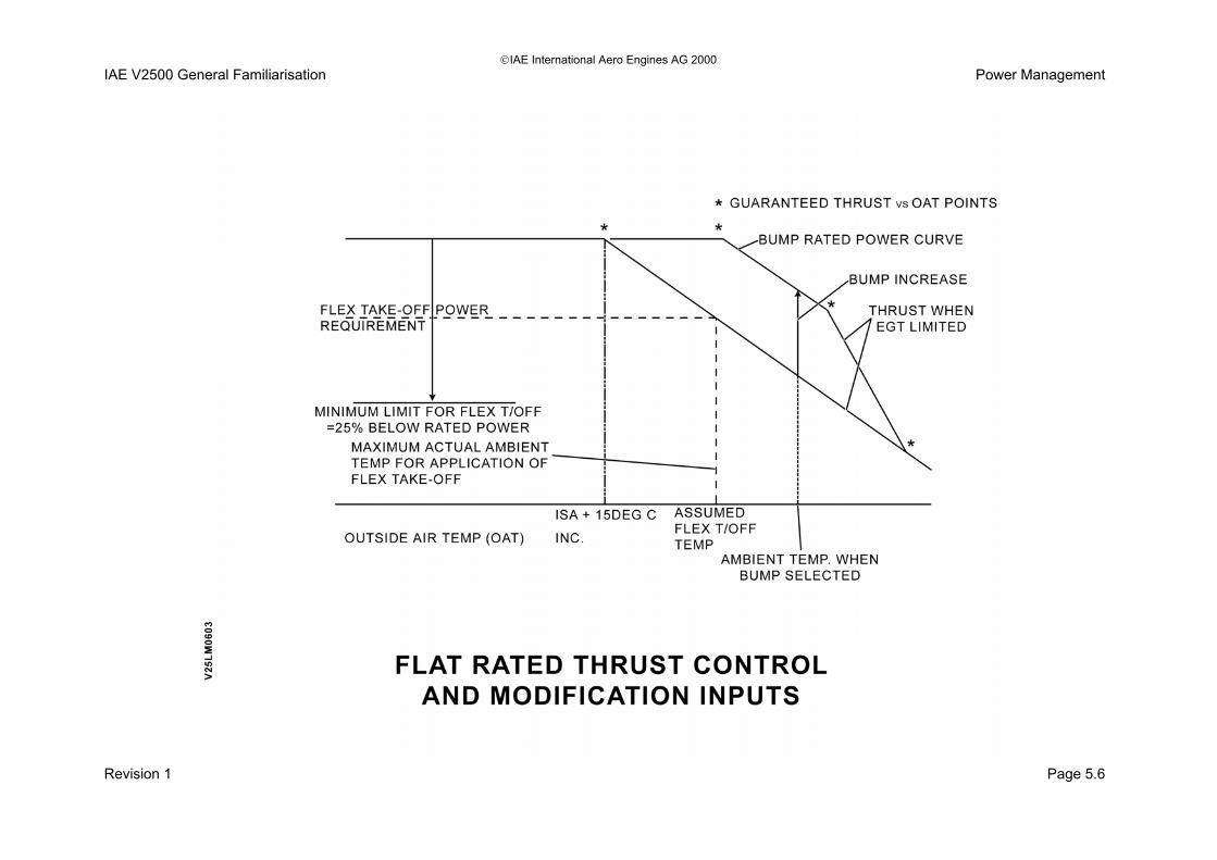
IAE International Aero Engines AG 2000 IAE V2500 General Familiarisation Power Management Bump Rating Push Button (A1 Engined Aircraft only) In some cases (optional) the throttle control levers are provided with "Bump" rating push buttons, one per engine. This enables the EEC to be re-rated to provide additional thrust capability for use during specific aircraft operations. Note: Bump Ratings can be selected, regardless of TLA only in EPR mode when aircraft is on ground. Bump Ratings can be de-selected at any time by actuating the bump rating push button, as long as the aircraft is on the ground and the Thrust Lever is not in the Max Take-Off detent. In flight, the bump ratings are fully removed when the Thrust Lever is moved from the Take-Off detent to or below the Max Continuous detent. The Bump Rating is available in flight (EPR or N1 mode) under the following conditions;
• Bump Rating is initially selected on ground.
• Take-Off, Go Around TOGA Thrust position set.
• Aircraft is within the Take-Off envelope. When Bump Rating is selected a ‘B’ appears next to the associated EPR display. Use of Bump must be recorded. When one Bump button is selected, both engines are Bump Rated. Pressing Bump again deselects Bump Rating.
Flexible Takeoff (A1 & A5Engined Aircraft) Definition of Flexible Takeoff: In many instances, the aircraft takes off with a weight lower than the maximum permissible takeoff weight. When this happens, it can meet the required performance with a decreased thrust that is adapted to the weight: This is called ‘Flexible Takeoff’ and the thrust is called ‘Flexible Takeoff Thrust’. The use of Flexible Takeoff Thrust saves engine life. The maximum permissible takeoff weight decreases as temperature increases, so it is possible to assume a temperature at which the actual takeoff weight would be the limiting one. This temperature is called ‘Flexible Temperature’ or ‘Assumed Temperature’ and is entered into the FADEC via the MCDU PERF TO page in order to get the adapted thrust. Note! If the thrust ‘Bump’ is armed for takeoff and flexible thrust is used, the pilot must use the Takeoff Performance determined for the non-increased takeoff thrust (without Bump).
• Thrust must not be reduced by more than 25% of the full rated thrust.
Revision 1 Page 5-5
IAE International Aero Engines AG 2000 IAE V2500 General Familiarisation Power Management
Revision 1 Page 5.6

IAE International Aero Engines AG 2000 IAE V2500 General Familiarisation Power Management Throttle Control Lever Mechanism The throttle control lever moves over a range of 65 degrees, from minus 20 degrees to plus 45 degrees. An intermediate retractable mechanical stop is provided at 0 degrees. Forward Thrust Range The forward thrust range is from 0 degrees to plus 45 degrees.
• 0 degrees = forward idle power.
• 45 degrees = rated take off power. Two detents are provided in this range;
• Max climb (MCLB) at 25 degrees.
• Max continuous (MCT)/Flexible (de-rated) take off power (FLTO) at 35 degrees.
Reverse Thrust Range Lifting the reverse latching lever allows the throttle to operate in the range 0 degrees to minus 20 degrees. A detent at minus 6 degrees corresponds to thrust reverse deploy commanded and reverse idle power, minus 20 degrees is max reverse power. Auto Thrust System (ATS) The Auto Thrust System can only be engaged between 0 degrees and plus 35 degrees.
Thrust Rating Limit Thrust rating limit is computed according to the thrust lever position. If the thrust lever is set in a detent the FADEC will select the rating limit corresponding to this detent. If the thrust lever is set between two detents the FADEC will select the rating limit corresponding to the higher mode.
Revision 1 Page 5-7

IAE International Aero Engines AG 2000 IAE V2500 General Familiarisation Power Management
Revision 1 Page 5-8

IAE International Aero Engines AG 2000 IAE V2500 General Familiarisation Power Management EEC/Fuel System Interface Purpose To allow the throttle signal from the flight deck to be received by the EEC. The EEC will convert this signal into a fuel flow error in order to change the fuel flow for a power level change. Description Movement of the pilots throttle control lever is sensed by the dual resolvers that signal the TRA to the EEC. The EEC computes the fuel flow that will produce the required thrust. The computed fuel flow request is converted to an electrical current (I) which drives the torque motor in the Fuel Metering Unit (FMU) which modulates fuel servo pressure to move the Fuel Metering Valve (FMV) and sets the fuel flow. Movement of the FMV is sensed by a dual resolver which is located in the fuel-metering unit next to the FMV. The dual resolver translates the fuel metering valve movement into an electrical feedback signal that is fed back to the EEC.
Revision 1 Page 5-9

IAE International Aero Engines AG 2000 IAE V2500 General Familiarisation Power Management
Revision 1 Page 5-10


SECTION 6
FUEL SYSTEM

© IAE International Aero Engines AG 2000 IAE V2500 General Familiarisation Fuel System Fuel System Introduction Purpose The primary purpose of the fuel system is to provide a completely controlled continuous fuel supply in a form suitable for combustion, to the combustion system. Description Control of the fuel supply is by the EEC via the Fuel Metering Unit (FMU). High pressure fuel is also used to provide servo pressure (actuator muscle) for the following actuators;
• BSBV actuators.
• VSV actuator.
• ACC actuator.
• ACOC actuator. The major components of the fuel system include;
• High and low pressure fuel pumps (dual unit).
• Fuel/oil heat exchanger.
• Fuel filter.
• Fuel metering unit (FMU).
• Fuel distribution valve.
• Fuel injectors (20).
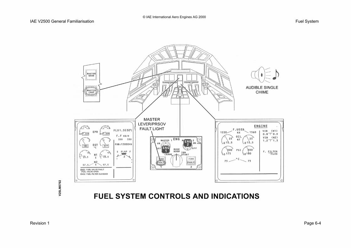
• Fuel diverter and back to tank valve (FDRV). The fuel system controls are on the centre control pedestal and the indications are in the form of an annunciator light and ECAM messages.
Operation The aircraft pumps deliver the fuel to the engine LP pump. The LP pump boosts the initial fuel delivery to a pressure so as to prevent low pressure entry into the HP pump. Nominal pressure 150psi. The fuel flows into the fuel oil heat exchangers for the engine and IDG. Depending on the mode of operation the heat management system is in depends on which direction the fuel will flow. From the engine FCOC the fuel passes through the LP fuel filter. The filter has a 40 micron filtration capability. The fuel is received by the HP pump and is boosted to a nominal 1000 psi. The HP pump has pressure relief set at 1360 psi. The FMU meters the fuel and the excessive HP fuel is diverted back into the LP supply. The FMU is controlled by signals from the EEC. The fuel flow meter gives indication to the upper ECAM screen of real time fuel flow in KG/H. The distribution valve filters the fuel and splits the supply into ten separate outlets. The ten outlets supply fuel to two fuel spray nozzles per outlet. The fuel spray nozzles have small filters within them. This gives last chance filtration prior to fuel atomisation.
Revision 1 Page 6-1

© IAE International Aero Engines AG 2000 IAE V2500 General Familiarisation Fuel System
Revision 1 Page 6-2

© IAE International Aero Engines AG 2000 IAE V2500 General Familiarisation Fuel System Fuel System Controls and Indications Controls The fuel metering valve is controlled by the selection of the master lever located on the centre control pedestal. The EEC has biased control of the FMU PRSOV for fuel selection to on and fuel selection to off, if N2 is below 50% and the start sequence is in auto. The command for fuel selection to off when the indicated N2 speed is above 50% is from the master lever. Indications The fuel temperature sensor is used by the EEC for the function of the heat management system. The fuel filter differential pressure switch annunciates to the lower ECAM screen a message of FILTER CLOG. This message is located in the right hand upper memo box. The message of FILTER CLOG will occur when the fuel filter differential pressure exceeds 5 psi. If there is a disagreement between the selection of the master lever and the PRSOV position then a fault exists.
Revision 1 Page 6-3
© IAE International Aero Engines AG 2000 IAE V2500 General Familiarisation Fuel System
Revision 1 Page 6-4

© IAE International Aero Engines AG 2000 IAE V2500 General Familiarisation Fuel System Fuel Pumps Purpose The fuel pumps are designed to ensure that the fuel system recieves fuel at a determined pressure in order to allow the atomisation of fuel in the combustion chamber. Description The combined fuel pump unit consists of low pressure and high pressure stages that are driven from a common gearbox, output shaft. LP fuel pump Purpose To provide the necessary pressure increase to;
• Account for pressure losses through the Fuel Cooled Oil Cooler and the LP fuel filter.
• Suppress cavitation. • Maintain adequate pressure at the inlet to the HP
stage. Description Shrouded, radial flow, centrifugal impeller, with an axial inducer.
HP Stage Purpose To increase the fuel pressure to that which will ensure adequate fuel flow and good atomisation at all engine operating conditions. Description Two gear (spur gear) pump.
• Provides mounting for fuel metering unit (FMU).
• Integral relief valve.
Revision 1 Page 6-5

© IAE International Aero Engines AG 2000 IAE V2500 General Familiarisation Fuel System
Revision 1 Page 6-6

© IAE International Aero Engines AG 2000 IAE V2500 General Familiarisation Fuel System Fuel Cooled Oil Cooler Purpose To transfer heat from the oil system to the fuel system to;
• Reduce the temperature of the engine lubricating oil under normal conditions.
Prevent fuel icing. Location The fuel and oil heat exchanger is located on the left hand side of the intermediate case. In the nine o’clock position. Description The fuel and oil heat exchanger is a single pass for the flow of fuel and multi pass for the flow of oil. The fuel and oil heat exchanger has the following features;
• A single casing houses the Fuel Cooled Oil Cooler and the LP fuel filter.
• Provides location for the fuel diverter and back to tank valve (unit not shown).
• Fuel temperature thermocouple.
• Fuel differential pressure switch.
• Oil system bypass valve.
• Fuel/oil tell tale leak indicator.
Revision 1 Page 6-7

© IAE International Aero Engines AG 2000 IAE V2500 General Familiarisation Fuel System
Revision 1 Page 6-8

© IAE International Aero Engines AG 2000 IAE V2500 General Familiarisation Fuel System Low pressure Fuel Filter Purpose To remove solid contaminants from the LP part of the fuel system. Location The LP fuel filter is located in the LP fuel filter housing that is integral with the fuel and oil heat exchanger. Description The LP fuel filter is a woven, glass fibre, disposable, 40 micron (nominal) type. The LP fuel filter and housing have the following features;
• A differential pressure switch, which generates a flight deck message, FUEL FILTER CLOG, if the differential pressure across the filter, reaches 5 psid.
• A by-pass valve which opens and allows fuel to by-pass the filter if the differential pressure reaches 15 psid.
• A fuel drain plug, used to drain filter case or to obtain fuel samples.
• Fuel temperature sensor.
Revision 1 Page 6-9

© IAE International Aero Engines AG 2000 IAE V2500 General Familiarisation Fuel System
Revision 1 Page 6-10

© IAE International Aero Engines AG 2000 IAE V2500 General Familiarisation Fuel System Fuel Metering Unit (FMU) Purpose The FMU has three functions for fuel control. They are;
• Fuel metering to the combustion chamber.
• Control of the opening and closing off of the fuel supply to the combustion chamber.
• Overspeed protection. Location The FMU is mounted on the combined fuel pumps assembly. The combined fuel pumps assembly is located on the rear face of the high-speed gearbox, left hand side. Description The FMU is the interface between the EEC and the fuel system. All the fuel delivered by the HP fuel pumps, which is more than the engine requires is passed to the FMU. The FMU, under the control of the EEC, meters the fuel supply to the fuel spray nozzles. The HP fuel pressure also provides a servo operation (muscle) for the following actuators;
• Booster stage bleed valve (BSBV) actuators.
• Variable stator vane (VSV) actuator.
• Active clearance control (ACC) actuator.
• Air cooled oil cooler (ACOC) actuator.
Excessive HP fuel supplies that are not required, other than that for actuator control and metered fuel to the combustor, is returned to the LP system via the spill valve. In addition to the fuel metering function the FMU also houses the overspeed valve and the pressure raising and shut off valve. The overspeed valve under the control of the EEC provides overspeed protection for the LP (N1) and HP (N2) rotors. The pressure raising and shut off valve provides a means of isolating the fuel supplies to start and stop the engine. Note: There are no mechanical inputs to, or outputs from, the FMU.
Revision 1 Page 6-11
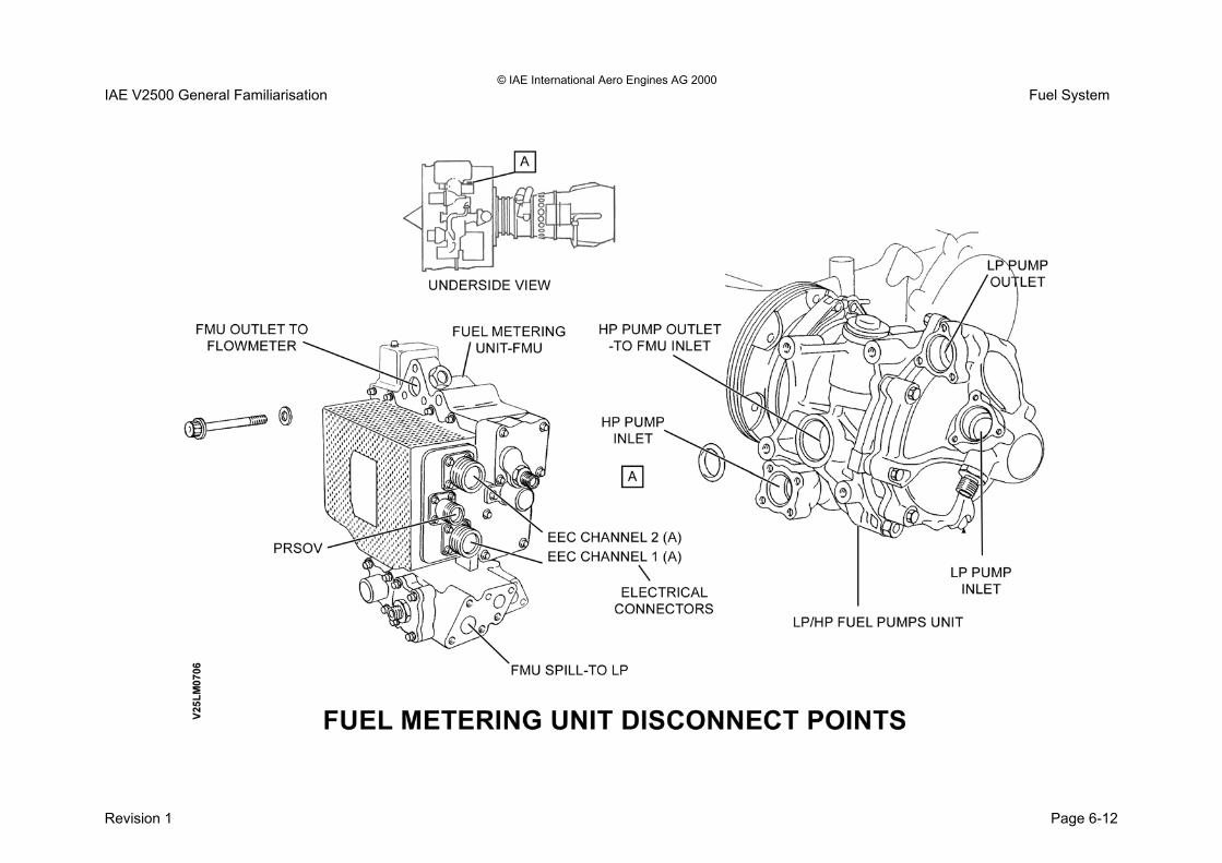
© IAE International Aero Engines AG 2000 IAE V2500 General Familiarisation Fuel System
Revision 1 Page 6-12

IAE International Aero Engines AG 2000 IAE V2500 General Familiarisation Fuel System Fuel System
Fuel Metering Unit (FMU) Service Bulletin V2500-ENG-73-0172 This Service Bulletin introduces a Woodward Governor Company FMU similar to the existing unit except for a ‘Common Flow/High Flow’ maximum fuel flow stop assembly. This allows the unit to be switched to suit all V2500-A5 model applications. This is considered logistically advantageous for mixed fleet operators. The changes introduced are:
a) The external single set fuel flow stop mechanism has been deleted.
b) An external switchable two-position maximum fuel flow stop has been introduced which can be set for either A319/A320 or A321 aircraft applications
c) A single reversible nameplate is introduced which, in conjunction with stop setting letter and FMU dataplate directive, will facilitate clear unambiguous identification of each flow setting.
d) A security seal system is introduced onto the above switchable fuel flow stop and reversible nameplate.
e) To facilitate installation of the security seal lock wire, the two existing retaining cap screws have been replaced by lockwire compatible equivalents.
FMU Part Number Position Setting Letter FMU 8061-636 0 FMU 8061-637 X
(i)To switch 8061-636 to 8061-637, carryout switch procedure in accordance with Woodward Governor Company Service Bulletin 83724-73 Fuel Metering Unit (FMU)
Service Bulletin V2500-ENG-73-0172 (Continued)
(ii) To switch 8061-637 to 8061-636, carryout switch procedure in accordance with Woodward Governor Company Service Bulletin 83724-73-0004.
a) Re-connect engine harness and LP fuel tube (Refer to AMM 73-22-52)
b) Close access to the engine (Refer to AMM 71-13-00)
c) Do an ‘idle’ check (Refer to AMM 71—00-00) or a wet motor leak test (Refer to AMM 71-00-00)
d) Do the operational tests of the starter and FMU (Refer to AMM 80-13-51)
Do the operational FADEC test as per (AMM 73-22-00)
Revision 1 Page 6-13

© IAE International Aero Engines AG 2000 IAE V2500 General Familiarisation Fuel System
Revision 1 Page 6-14

© IAE International Aero Engines AG 2000 IAE V2500 General Familiarisation Fuel System Fuel Distributor Valve Purpose The fuel distributor valve receives fuel from the FMU and carries out three functions;
• Last chance filtration of the metered fuel.
• Distribution of the metered fuel through ten fuel supply tubes to the fuel spray nozzles.
• Upon shut down allows fuel drain back (pressure reduction) for prevention of fuel leaks into the combustor upon engine shut down.
Location The fuel distribution manifold is located on the right hand side of the combustion diffuser casing. It is in the 4 o’clock position. Description The fuel distributor manifold has the following features;
• Integral fuel filter - with by-pass valve.
• Single fuel metering (check) valve.
• Spring loaded closed upon engine shut down.
• Fuel pressure opened.
• Ten fuel outlet ports.
Revision 1 Page 6-15

© IAE International Aero Engines AG 2000 IAE V2500 General Familiarisation Fuel System
Revision 1 Page 6-16

© IAE International Aero Engines AG 2000 IAE V2500 General Familiarisation Fuel System Fuel Spray Nozzles (FSN) Purpose To inject the fuel into the combustion chamber in a form suitable for combustion by;
• Atomising the fuel.
• Mixing it with HPC delivery air.
• Controlling the spray pattern. Location The fuel spray nozzles are equi spaced around the circumference of the combustor diffuser casing. Description Parker Hannifin manufactures the Airspray fuel nozzles. The fuel spray nozzles have the following features;
• 20 fuel spray nozzles.
• Inlet fitting houses fuel filter.
• Internal and external heat shields to reduce coking.
• Transfer tubes for improved fuel leak prevention.
Revision 1 Page 6-17

© IAE International Aero Engines AG 2000 IAE V2500 General Familiarisation Fuel System
Revision 1 Page 6-18

© IAE International Aero Engines AG 2000 IAE V2500 General Familiarisation Fuel System Fuel System Operation Fuel Metering Unit Description A simplified schematic representation of the Fuel Metering Unit is shown below. The three main functions of the FMU are;
• Metering the fuel supplies to the fuel spray nozzles.
• Overspeed protection for both the LP (N1) and HP (2) rotors.
• Isolation of fuel supplied for starting/stopping the engine.
Three valves arranged as follows carry out these three functions;
• The Fuel Metering Valve.
• The Overspeed Valve.
• The Pressure Raising and Shut Off Valve (PRSOV). Fuel metering valve The fuel metering valve varies the fuel flow according to the EEC command. The positional feedback to the EEC is by a rotary variable displacement transducer (RVDT). The overspeed valve The overspeed valve protects the engine against an exceedance of;
• N1 shaft speed. (109%)
• N2 shaft speed. (105.7%)
The feedback to the EEC of the valve operation is by a micro switch. The pressure raising and shut of valve (PRSOV) The PRSOV is an open and close type valve. The PRSOV controls the fuel to the combustor. When the valve is in the pressure raising state it is said to be open. When the valve is in the shut off state it is said to be closed. Note: The EEC has command to open the PRSOV upon an engine start. The EEC has command to close the PRSOV in auto start mode and when the N2 is below 50%. Above 50% N2 the close command is from the master lever in the flight deck only. Pressure drop governor and spill valve The pressure drop governor controls the pressure difference across the FMV. The spill valve is controlled by the pressure drop governor. The spill valve is designed to vary the excessive HP fuel pressure return to the LP system.
Revision 1 Page 6-19

© IAE International Aero Engines AG 2000 IAE V2500 General Familiarisation Fuel System
Revision 1 Page 6-20


SECTION 7
ENGINE OIL SYSTEM

© IAE International Aero Engines AG 2000 IAE V2500 General Familiarisation Engine Oil System Engine Oil System Introduction Purpose The oil system is a self contained, full flow recirculating type design to ensure reliable lubrication and cooling under all circumstances. Description Oil cooling is controlled by a dedicated Heat Management System which ensure that engine oil, IDG oil and fuel temperatures are maintained at acceptable levels while ensuring the optimum cooling configuration for the best engine performance. The engine oil system can be divided into three sections. These sections are;
• Pressure feed.
• Scavenge.
• Venting. Pressure feed The pressure feed system uses the full flow generated by the pressure pump. The pressure pump moves the oil through;
• The pressure filter.
• Fuel oil heat exchanger. The oil is then distributed to the engine bearings and gear drives.
Scavenge The scavenge system is designed to retrieve the oil that is present in the bearing chambers and gearbox for cooling and recirculation. There are six scavenge pumps that are designed to suck the oil and pass it through;
• Magnetic chip detectors.
• A scavenge filter and master chip detector. Prior to returning the oil back to the oil tank. Venting The venting system is designed to allow the air and oil mix that develops in the bearing chambers and gearbox to escape to the de oiler. No.4 bearing does not have a scavenge pump. It relies upon the build up of air pressure in the bearing chamber to force the air and oil through the no.4 bearing scavenge valve and into the de oiler. Indications There are flight deck indications that allow the oil system to be monitored. There are also messages generated ECAM for further flight crew awareness.
Revision 1 Page 7-1

© IAE International Aero Engines AG 2000 IAE V2500 General Familiarisation Engine Oil System
Revision 1 Page 7-2

© IAE International Aero Engines AG 2000 IAE V2500 General Familiarisation Engine Oil System Engine Oil System Indications The operation of the engine oil system may be monitored by the following flight deck indications; • Engine oil pressure. • Engine oil temperature. • Oil tank contents. In addition ECAM alerts may be given for the following non-normal conditions: - • Low oil pressure. • Scavenge filter clogged or partly clogged (high
differential pressure). • No 4 compartment scavenge valve inoperative. The oil system parameters are displayed on the Engine page on the Lower ECAM screen. Oil temperature (deg.c) Normal indication to ECAM is GREEN. 156°C or above flashing green indication. 156°C or above more than 15 minutes or 165°C without delay steady amber indication. Upper ECAM message ENG 1(2) OIL HI TEMP-Level 2. Oil low temperature alert, throttle above idle and engine running. Upper ECAM message ENG 1(2) OIL LO TEMP-level 2. Single chime. Master caution light.
Oil quantity Normal indication to ECAM is GREEN. Less than 5 quarts flashes green. Oil pressure Normal indication to ECAM is GREEN. 390 psid or above indication flashes. 60-80 psid amber indication. Upper ECAM amber message ENG OIL LO PR level 1. 60 psid or below red indication. Master warning light. Continuous repetitive chime. Upper ECAM red message level 3; ENG 1(2) OIL LO PR THROTTLE 1(2) IDLE Scavenge filter clog If the filter differential pressure is greater than 12 psi oil filter clog message appears on Engine page, lower ECAM. Oil Consumption Acceptable oil use is not more than 0.6 US pts/hr (0.5 Imp pts/hr). Oil increase of 100 cc’s or more analyse sample for fuel contamination. master caution light single chime
Revision 1 Page 7-3

© IAE International Aero Engines AG 2000 IAE V2500 General Familiarisation Engine Oil System
Revision 1 Page 7-4

© IAE International Aero Engines AG 2000 IAE V2500 General Familiarisation Engine Oil System Oil System Bearings and Gears Lubrication Front Bearing Compartment (Bearings no. 1, 2, 3) Purpose Bearings and gears require oil for;
• Lubrication.
• Cooling.
• Vibration suppression. Location The following bearings and gears are located in the front bearing compartment;
• Ball bearing no.1.
• Roller bearing no.2.
• Ball bearing no.3. Description The bearing chamber utilises hydraulic seals and carbon seals to contain the oil within the bearing chamber. The front seal has LPC booster stage 2.5 air passing across the seal in order to prevent oil loss. The rear seal has LPC 2.5 air passing across the seal in order to prevent oil loss.
The bearings and gears are fed with oil by utilising oil jets that liberally allow oil to enter the bearing area. The front bearing compartment has;
• Oil fed from the pressure pump.
• Scavenge oil recovery by the scavenge pumps.
• Vent air outlet to allow the sealing air to escape to the de oiler.
Revision 1 Page 7-5

© IAE International Aero Engines AG 2000 IAE V2500 General Familiarisation Engine Oil System
Revision 1 Page 7-6

© IAE International Aero Engines AG 2000 IAE V2500 General Familiarisation Engine Oil System Oil System Bearings and Gears Lubrication Centre Bearing Compartment (Bearing no.4) Purpose Bearings require oil for;
• Lubrication.
• Cooling. Location The following bearing is located in the centre bearing compartment;
• Roller bearing no.4. Description The centre bearing compartment is the hottest compartment in the engine. In order to maintain the bearing at an acceptable operating temperature HPC12 air is taken from the engine, it is cooled by an air cooled air cooler (ACAC) and passed back into the engine. This cooling and sealing air is called buffer air. The buffer cooling air supply flows around the outside of the bearing in a cooling type jacket. In addition to cooling the buffer air is allowed to pass across the carbon seal and pressurise the no.4 bearing.
This bearing compartment has the following;
• Oil fed from the pressure pump.
• Scavenge oil and vent air recovery by the build up of pressure in the bearing compartment forcing the air and oil out. The air and oil passes through the no.4 bearing scavenge valve and then into the de oiler.
Revision 1 Page 7-7

© IAE International Aero Engines AG 2000 IAE V2500 General Familiarisation Engine Oil System
Revision 1 Page 7-8

© IAE International Aero Engines AG 2000 IAE V2500 General Familiarisation Engine Oil System Oil System Bearings and Gears Lubrication Rear Bearing Compartment (Bearing no.5) Purpose Bearings require oil for;
• Lubrication.
• Cooling.
• Vibration suppression. Location The following bearing is located in the rear bearing compartment;
• Roller bearing no.5. Description The rear bearing compartment has one carbon seal. This seal allows HPC8 air to leak across the seal thus preventing oil loss from the bearing compartment. This bearing compartment has the following;
• Oil fed from the pressure pump.
• Scavenge oil recovery by the scavenge pumps. There is no vent outlet. The vent air is removed from the bearing compartment along with the scavenge oil. The presence of vent air in the scavenge oil is used to pressurise the oil tank.
Excess air pressures that develop in the oil tank vent to the de oiler.
Revision 1 Page 7-9

© IAE International Aero Engines AG 2000 IAE V2500 General Familiarisation Engine Oil System
Revision 1 Page 7-10

© IAE International Aero Engines AG 2000 IAE V2500 General Familiarisation Engine Oil System Oil System Bearings and Gears Lubrication High speed external gearbox Purpose Gears require oil for;
• Lubrication.
• Cooling.
• Vibration suppression. Location The following module is located at the six o’clock position on the intermediate module. Description The high speed external gearbox is a one piece casting consisting of the following;
• Gear trains.
• Oil jets.
• Two scavenge outlets with strainers.
• Vent out to the de oiler.
• Integrally mounted oil tank.
• Angle gearbox.
• Accessory units. The gear ratios differ to suit the rotational operating speeds of the accessory units.
The high speed external gearbox gears are lubricated by;
• Oil jets directing the oil onto the gears.
• Splash lubrication caused by the motion of the gears. The high speed external gearbox has;
• Oil fed from the pressure pump.
• Scavenge oil recovery by two scavenge pumps.
• Vent air outlet to allow the vent air to escape to the de oiler.
Revision 1 Page 7-11

© IAE International Aero Engines AG 2000 IAE V2500 General Familiarisation Engine Oil System
Revision 1 Page 7-12

© IAE International Aero Engines AG 2000 IAE V2500 General Familiarisation Engine Oil System Oil Tank Purpose To store the dedicated engine oil supply. Location Located to the top LH side of the external gearbox. Description The engine oil tank has the following features; Pressurised hot tank. Oil quantity transmitter.
• Gravity fill port with safety flap.
• Sight glass oil level indicator.
• Internal 'cyclone' type de aerator.
• Tank pressurisation valve (6 psi) ensures adequate pressure at inlet to oil pressure pump.
• Strainer in tank outlet to pressure pump.
• Provides mounting for scavenge filter and master magnetic chip detector (MCD).
The oil tank has the following for oil capacity;
• Tank capacity is 29 US quarts.
• Usable oil 24 US quarts. There is an anti siphon tube that supplies a small flow of oil back to the tank. This flow of oil splashes across the sight glass providing a cleaning action that prevents the build up of impurities.
On early A1 engines the oil tanks were fitted with a Prismalite oil level indicator, no sight glass was fitted.
Revision 1 Page 7-13

© IAE International Aero Engines AG 2000 IAE V2500 General Familiarisation Engine Oil System
Revision 1 Page 7-14

© IAE International Aero Engines AG 2000 IAE V2500 General Familiarisation Engine Oil System Pressure Pump and Pressure Filter Assembly Purpose The pressure pump is designed to produce oil pressure for distribution in the bearing chambers and high speed external gearbox. The pressure filter gives initial filtration of the oil as it leaves the oil tank. Location The pressure pump and filter are one assembly. They are located on the front face of the high speed external gearbox. Mounted to the left hand side. Description The pressure pump and filter assembly has the following features;
• Cold start pressure limiting valve.
• Flow trimming valve (Line adjustment not permissible).
• 125 micron filtration strength pressure filter.
• Oil priming ports.
• Anti drain valve.
Revision 1 Page 7-15

© IAE International Aero Engines AG 2000 IAE V2500 General Familiarisation Engine Oil System
Revision 1 Page 7-16

© IAE International Aero Engines AG 2000 IAE V2500 General Familiarisation Engine Oil System Air/Oil Heat Exchanger (Air Cooled Oil Cooler) Purpose The air cooled oil cooler acts as a second cooler for the oil system. The heat management system of the EEC controls the operation of this unit. Location Attached to the fan casing on the lower RH side. Description The air oil heat exchanger is normally closed when the engine fuel and oil temperatures are operating within their required temperature ranges. During certain conditions of engine operation the fuel and oil temperatures may experience high temperatures. The air cooled oil cooler acts to cool the oil in order for the oil to cool the fuel. The air cooled oil cooler has the following features;
• Corrugated fin and tube with a double pass design.
• Oil by pass valve.
• Modulated air flow as commanded by EEC (heat management system) Air flow regulated by air control valve.
• Electro-hydraulic servo valve operated system.
Note: The oil has a continuous flow through the air cooled oil cooler. This is regardless of wether the valve is open or closed. Main oil cooling is carried out by the fuel oil heat exchanger.
Revision 1 Page 7-17

© IAE International Aero Engines AG 2000 IAE V2500 General Familiarisation Engine Oil System
Revision 1 Page 7-18

© IAE International Aero Engines AG 2000 IAE V2500 General Familiarisation Engine Oil System Fuel/Oil Heat Exchanger Purpose The purpose of the fuel oil heat exchanger is to;
• Cool the engine oil.
• Heat the fuel. Location The location of the fuel oil heat exchanger is on the left hand side of the intermediate case. Description The fuel oil heat exchanger is a;
• Single pass fuel flow.
• Multi pass oil flow. Forms an integral unit with the LP fuel filter. A differential pressure relief valve permits oil to by-pass part of the cooler if the oil pressure is high during initial engine running, following a cold start.
Revision 1 Page 7-19

© IAE International Aero Engines AG 2000 IAE V2500 General Familiarisation Engine Oil System
Revision 1 Page 7-20

© IAE International Aero Engines AG 2000 IAE V2500 General Familiarisation Engine Oil System Scavenge Pumps Unit Purpose Returns scavenge oil to the tank. Location All 6 scavenge pumps are housed together as a single unit on the rear of the high speed external gearbox, left hand side. Description The scavenge pumps assembly consists of six gear type pumps that are designed to retrieve the oil from the gearbox and bearing chambers. Thus returning the oil back to the oil tank. The scavenge pump capacity is determined by the gear width.
Revision 1 Page 7-21

© IAE International Aero Engines AG 2000 IAE V2500 General Familiarisation Engine Oil System
Revision 1 Page 7-22

© IAE International Aero Engines AG 2000 IAE V2500 General Familiarisation Engine Oil System De oiler Purpose To separate the air and oil mixture that develops in the bearing compartments and gearbox. To return the oil back to the oil tank and eject the air overboard. Location The de oiler is located on the front face of the high speed external gearbox, fight hand side. Description The de oiler has the following features;
• Provides mounting for the No.4 bearing chamber scavenge valve.
• Overboard vent.
• Provides location for No.4 bearing Magnetic Chip Detector housing.
The de oiler is also called a centrifugal separator. This due to the fact that it relies upon the centrifugal force of a rotating body to separate the oil from the air. The oil is centrifuged outwards and into the gearbox. The air is induced inwards an out through the discharge slots. .
Revision 1 Page 7-23

© IAE International Aero Engines AG 2000 IAE V2500 General Familiarisation Engine Oil System
Revision 1 Page 7-24

© IAE International Aero Engines AG 2000 IAE V2500 General Familiarisation Engine Oil System Scavenge Filter Purpose To trap solid contaminants. Location Mounted to the rear of the oil tank. Description The scavenge filter has the following features;
• The filter is disposable.
• The filter has a by pass valve.
• There is a differential pressure switch monitoring filter for contamination.
• The master magnetic chip detector housing is located on the filter housing.
Mesh type filter that is disposable. The scavenge filter has a nominal 30 micron filtration capability.
Revision 1 Page 7-25

© IAE International Aero Engines AG 2000 IAE V2500 General Familiarisation Engine Oil System
Revision 1 Page 7-26

© IAE International Aero Engines AG 2000 IAE V2500 General Familiarisation Engine Oil System No 4 Bearing Scavenge Valve Purpose Maintains the centre bearing compartment (No 4 bearing) seal deferential pressure by controlling the venting of the compartment air/oil mixture to the de oiler. Location The no.4 bearing scavenge valve is located on the front of the de oiler, of which the de oiler is located on the front face of the high speed external gearbox. Description The no.4 bearing scavenge valve has the following features;
• Operational feed back signal to EIU.
• Uses HPC10 air as the servo air for the valve operation.
• Stage 10 air less than 150 psi the valve is at maximum open position.
• Stage 10 air more than 200 psi the valve is at minimum open position.
• Feedback to EIU of valve operation is the valve position indicator, scavenge oil pressure sensor and Pb indication from the EEC.
The no.4 bearing scavenge valve controls the flow of the scavenge oil and vent air by varying the size of the orifice of the valve. This allows the scavenge oil and vent air to enter the de oiler under controlled conditions.
High flow When the valve is at the high flow position the engine is at low power. Therefor the valve is fully open and the pressure differential is maintained across the carbon seal. This has the effect of allowing the buffer air to pressurise the bearing compartment without an excessive flow that could dry the seal. Low flow When the valve is at the low flow position the engine is at high power. Therefor the valve is fully closed and the pressure differential is maintained across the carbon seal. This has the effect of increasing the back pressure of scavenge oil and vent air that is leaving the bearing compartment. Increasing the back pressure maintains the seal differential within acceptable limits. Note: High flow at high power will cause a lower seal differential pressure. This will lead to the flow of buffer air across the carbon seal to increase. The increase flow of buffer air leads to the carbon seal drying out.
Revision 1 Page 7-27

© IAE International Aero Engines AG 2000 IAE V2500 General Familiarisation Engine Oil System
Revision 1 Page 7-28

© IAE International Aero Engines AG 2000 IAE V2500 General Familiarisation Engine Oil System Magnetic Chip Detectors (MCD) Purpose The magnetic chip detectors (MCDs) give on condition monitoring of the gears and bearing assemblies. They can indicate when a wear mechanism is present. Location The MCDs are located about the high speed external gearbox. The Master MCD is located at the inlet to the scavenge filter. Description A total of 7 MCD’s are used in the oil scavenge system. The MCDs have the following common features;
• The MCDs are of a bayonet style.
• Dual seal rings.
• Baulking pin preventing complete insertion in the case of a missing seal.
• Separate removable housing. Each bearing compartment and gearbox has its own dedicated MCD (two in the case of the main gearbox). The No4 bearing is located in the de-oiler scavenge outlet. An additional MCD is located in the combined scavenge return line, at the scavenge filter inlet. This is known as the Master MCD. The Master MCD is accessible through its own access panel in the LH fan cowl door.
If the master MCD indicates a problem then each of the other MCD’s are inspected to indicate the source of the problem. Access to the dedicated MCD’s is by opening the L and R hand fan cowls.
Revision 1 Page 7-29

© IAE International Aero Engines AG 2000 IAE V2500 General Familiarisation Engine Oil System
Revision 1 Page 7-30

© IAE International Aero Engines AG 2000 IAE V2500 General Familiarisation Engine Oil System Master Magnetic Chip Detector Purpose The master MCD gives indication for all gears and bearings of the engine. It allows periodic inspection without the requirement to inspect all MCDs. Location The master MCD can be accessed from a dedicated panel on the left hand side fan cowl door. Description The master magnetic chip detector is located in the scavenge filter case. The MCD is at the inlet to the filter. If debris is found on the MCD head then further confirmation as to the source can be had by inspecting all the MCDs. Further confirmation still can be had by inspecting the scavenge filter.
Revision 1 Page 7-31

© IAE International Aero Engines AG 2000 IAE V2500 General Familiarisation Engine Oil System
Revision 1 Page 7-32

© IAE International Aero Engines AG 2000 IAE V2500 General Familiarisation Engine Oil System Differential Oil Pressure Transmitter and Low Oil Pressure Warning Switch Purpose The pressure transmitter is designed to give real time indication to the ECAM of differential oil pressure. The low pressure switch is designed to give warning of minimum operating differential oil pressure to ECAM. Location The differential oil pressure transmitter and low oil pressure switch are located on the left hand side intermediate case. Located in the 10 o’clock position. Description The pressure transmitter and low oil pressure switch differential pressures are sampled from;
• Pressure feed to the no.4 bearing.
• Scavenge oil from the no.4 bearing.
Revision 1 Page 7-33

© IAE International Aero Engines AG 2000 IAE V2500 General Familiarisation Engine Oil System
DETV252106
PRESSURE TRANSMITTER AND LOW PRESSURE SWITCH Revision 1 Page 7-34


SECTION 8
HEAT MANAGEMENT SYSTEM

© IAE International Aero Engines AG 2000 IAE V2500 General Familiarisation Heat Management System Heat Management System Purpose The system is designed to provide adequate cooling, to maintain the critical oil and fuel temperatures within specified limits, whilst minimising the requirement for the fan air offtake. Location The following units are located about the engine fan case;
• The engine FCOC.
• The engine ACOC.
• The IDG FCOC.
• The fuel diverter and back to tank valve.
• The aircraft outer wing fuel tanks. Description Three sources of cooling are available: -
• The LP fuel passing to the engine fuel system.
• The LP fuel that is returned to the aircraft fuel tanks.
• Fan air.
There are four basic configurations between which the flow paths of fuel in the engine LP fuel system are varied. The configurations are;
• Mode 1.
• Mode 3.
• Mode 4.
• Mode 5. Within each configuration the cooling capacity may be varied by control valves that form the fuel diverter and back to tank valve. The transfer between modes of operation is determined by software logic contained in the EEC. The logic is generated around the limiting temperatures of the fuel and oil within the system together with the signal from the aircraft that permits/inhibits fuel spill to aircraft tanks.
Revision1 Page 8-1

© IAE International Aero Engines AG 2000 IAE V2500 General Familiarisation Heat Management System
Revision1 Page 8-2

© IAE International Aero Engines AG 2000 IAE V2500 General Familiarisation Heat Management System Air/Oil Heat Exchanger Air Modulating Valve Purpose To govern the flow of cooling (fan) air through the air/oil heat exchanger, as commanded by the EEC heat management control system. Location The air/oil heat exchanger (ACOC) is attached to the right hand side of the engine fan case. It is in the four o’clock position as viewed from the rear of the engine looking forwards. Description The ACOC is a plate type heat exchanger. It is operated by an electro hydraulic servo valve mechanism. The following are features of the ACOC;
• Fail safe position is valve open for maximum cooling.
• Fire seal forms an air tight seal between the unit outlet and the cowling orifices.
• Control by either channel A or B of EEC.
• Valve position feed back signal via LVDT to each channel of EEC.
• Valve positioned by fuel servo pressure acting on a control piston.
• Fuel servo pressure directed by the electro hydraulic servo valve assembly which incorporates a torque motor.
The valve is operated via signals from the EEC heat management system. The electro-hydraulic servo valve directs a controlling fuel pressure to the operating piston. Depending on which side of the piston the fluid is present depends whether the valve opens or closes. An LVDT gives positional feedback to the EEC of the valves position.
Revision1 Page 8-3

© IAE International Aero Engines AG 2000 IAE V2500 General Familiarisation Heat Management System
Revision1 Page 8-4
© IAE International Aero Engines AG 2000 IAE V2500 General Familiarisation Heat Management System Air Control Valve Electro Hydraulic Servo Valve (EHSV) Purpose To provide the 'muscle' to move the air control valve to the EEC commanded position. Location Bolted to the air control valve casing. Description Two stage directional flow valve. The stages are;
• Stage 1 is an electrically activated torque motor and 'Jet pipe'.
• Stage 2 is a spool valve. The following are features of the EHSV;
• Two independent torque motor windings - one connected to each channel of EEC.
• Operation, from either channel of EEC.
• Jet pipe protected by 90 micron filter.
• Biased to ensure air control valve fully open at engine start condition.
• Single fuel servo supply from fuel metering unit (FMU).
Revision1 Page 8-5
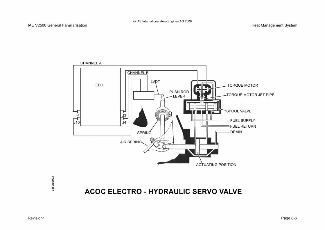
© IAE International Aero Engines AG 2000 IAE V2500 General Familiarisation Heat Management System
Revision1 Page 8-6

© IAE International Aero Engines AG 2000 IAE V2500 General Familiarisation Heat Management System Fuel Diverter and Back to Tank Valve Purpose The fuel diverter valve and the back to tank valve together form a single unit. Command signals of the EEC control the two valves. The two valves in turn manage the flow of high pressure fuel. This is done to optimise the heat exchange process that takes place between the fuel and oil. Location The unit is bolted to the rear of the fuel/oil heat exchanger. Description Fuel Diverter Valve This valve is a two position valve and is operated by a dual coil solenoid. The control signals to energise/de-energise the solenoid come from the EEC
• Solenoid energised - mode 1 or 3.
• Solenoid de-energised (fail safe position) mode 4 or 5. Back to Tank Valve This valve is a modulating valve and will divert a proportion of the LP fuel back to the aircraft tanks as controlled by the EEC. The interface between the EEC and the valve is a modulating torque motor; the torque motor will direct HP servo fuel to position the valve.
• Fail safe position is with the valve fully closed - no fuel return to tank.
Revision1 Page 8-7

© IAE International Aero Engines AG 2000 IAE V2500 General Familiarisation Heat Management System
Revision1 Page 8-8

© IAE International Aero Engines AG 2000 IAE V2500 General Familiarisation Heat Management System
Heat Management System Operation The following are the four modes of control for the heat management system. The system is fully automatic as controlled by the EEC. The four modes will be in effect when certain aircraft/engine operating conditions exist. Mode 1 (normal mode) In this mode all the heat from the engine oil system and the IDG oil system is absorbed by the LP fuel flows. Some of the fuel is returned to the aircraft tanks where the heat is absorbed or dissipated within the tank. This mode is maintained if the following conditions are satisfied: - • Engine not at high power setting (Take Off and early
part of climb (not below 25,000ft). • Cooling spill fuel temperature less than 100 deg C. • Fuel temperature at pump inlet less than 54 deg C. Mode 3 Mode 3 is the mode that is adopted when the requirements for fuel spill back to tank can no longer be satisfied i.e. • Engine at high power setting (below 25,000ft). • Spill fuel temperature above limits (100 deg C). • Tank fuel temperature above limits (54 deg C).
In this condition the burned fuel absorbs all the heat from the engine and I.D.G. oil systems. If however, the fuel flow is too low to provide adequate cooling the engine oil will be pre-cooled in the air/oil heat exchanger, by a modulated air flow, before passing to the fuel/oil heat exchanger. This is the preferred mode of operation, when return to tank is not allowed. Mode 4 Mode 4 is the mode adopted when the burned fuel flow is low. For example; Low engine speeds. High HP fuel pump inlet temperature. In this mode the fuel/oil heat exchanger is operating as a fuel cooler. The excessive heat is passed to the engine oil. The ACOC extracts the heat from the oil that has been heated up by the hot fuel. Mode 5 Mode 5 is the mode that is used when the system conditions demand operation as in mode 3, but is not permitted due to;
• IDG oil system temperature is excessive.
• The fuel spill to the aircraft tank is not permitted because of high spill fuel temperatures.
Mode 5 is the adopted position for the fail safe engine conditions.
Revision1 Page 8-9

© IAE International Aero Engines AG 2000 IAE V2500 General Familiarisation Heat Management System
Revision1 Page 8-10


SECTION 9
COMPRESSOR AIRFLOW CONTROL

© IAE International Aero Engines AG 2000 IAE V2500 General Familiarisation Compressor Airflow Control Compressor Airflow Control System Introduction Description/operation The engine incorporates two air bleed systems and a variable stator vane (V.S.V.) system, which together are used to: -
• Ensure stable airflow through the compressor at "off design" conditions.
• Ensure smooth, surge free, accelerations and decelerations (transient conditions).
• Improve engine-starting characteristics.
• In re-stabilising the engine if surge occurs (surge recovery).
The complete system comprises three sub-systems, which are: -
• An L.P. compressor air bleed located at engine station 2.5 and known as the Booster Stage Bleed Valve (B.S.B.V.)
• H.P. compressor air bleeds on stages 7 and 10.
• The V.S.V. system which comprises variable inlet guide vanes, at the inlet to the H.P. compressor, and 4 stages of variable stator vanes on the A1 and 3 stages on A5 engines.
The EEC controls all three systems A schematic overview of the complete airflow control system is shown below.
Revision 1 Page 9-1

© IAE International Aero Engines AG 2000 IAE V2500 General Familiarisation Compressor Airflow Control
Revision 1 Page 9-2

© IAE International Aero Engines AG 2000 IAE V2500 General Familiarisation Compressor Airflow Control L.P. Compressor Bleed Valve (LPCBV) - A5 Purpose The LPCBV bleeds air from the rear of the L.P. compressor at engine station 2.5, the bleed air is vented into the fan air duct. The bleed valve provides improved surge margins during starting, low power and transient operations. The bleed valve is controlled by the EEC and is fully modulating, between the fully open and fully closed positions this is a function of: -
• N1 corrected speed
• Altitude
• Aircraft forward speed (Mach Number) For starting the bleed valve is fully open and will progressively close during engine acceleration, during cruise and take off the valve is fully closed. For decelerations and engine operation in reverse thrust the valve is opened. In the event of an engine surge the valve is opened to enhance recovery.
LPCBV Mechanical Arrangement The L.P. Compressor Bleed Valve is a continuous ring Type valve, which rotates and slides forward to open and rearward to close. Ten support arms support the ring. Two of the support arms are driven via a lever and actuating rod by both the LPCBV master actuator and the slave actuator. The two actuators utilise H.P. fuel pressure (from the FMU) as the hydraulic medium and are hydraulically linked to ensure simultaneous movement. The master actuator interfaces with the EEC via a torque motor control and LVDT feedback. The mechanical linkage is shown below.
Revision 1 Page 9-3

© IAE International Aero Engines AG 2000 IAE V2500 General Familiarisation Compressor Airflow Control
Revision 1 Page 9-4

© IAE International Aero Engines AG 2000 IAE V2500 General Familiarisation Compressor Airflow Control Booster Stage Bleed Valve Component Description Actuators The two B.S.B.V. actuators utilise H.P. fuel as a hydraulic operating medium. The actuators are located on the rear of the intermediate casing on either side of the H.P. compressor, as shown below. Only one of the actuators, the one on the left hand side, interfaces with the EEC This actuator is called the Master actuator, the right hand side actuator is called the Slave actuator. The two actuators are hydraulically linked by two tubes, which pass across the top of the H.P. compressor case. The master actuator incorporates a Linear Variable Differential Transducer (L.V.D.T.) which transmits actuator positional information back to the EEC The slave actuator incorporates two overload relief valves, which prevent overpressurisation of the actuators in the case of faults, such as a mechanically seized actuator.
Revision 1 Page 9-5

© IAE International Aero Engines AG 2000 IAE V2500 General Familiarisation Compressor Airflow Control
Revision 1 Page 9-6

© IAE International Aero Engines AG 2000 IAE V2500 General Familiarisation Compressor Airflow Control Variable Stator Vane System (VSV) A5 Introduction Variable Incidence Stator Vanes control the entry of air into the H.P. compressor. The variable vanes control the angle at which the air enters the first five stages of the H.P. compressor. The angle varies with the H.P. compressor speed (N2); this reduces the risk of blade stall and compressor surge. The four stages of variable incidence stators comprise inlet guide vanes to stage 3 and stage 3, 4, and 5 stator vanes. Mechanical Arrangement Each vane has pivots at its inner and outer ends, which allow the vane to rotate about its longitudinal axis. The outer end of each vane is formed into a shaft, which passes through the compressor case and is attached by a short lever to a Unison ring, (one unison ring for each stage). Short rods to a crankshaft connect the four unison rings. A short rod to an actuator that utilises H.P. fuel as a hydraulic operating medium connects the crankshaft. Signals from the EEC direct H.P. fuel to extend/retract the actuator. Actuator movement causes the crankshaft to rotate, and, through the unison rings, reposition the variable stator vanes. The actuator incorporates an L.V.D.T. which signals actuator positional information back to the EEC
Revision 1 Page 9-7

© IAE International Aero Engines AG 2000 IAE V2500 General Familiarisation Compressor Airflow Control
Revision 1 Page 9-8

© IAE International Aero Engines AG 2000 IAE V2500 General Familiarisation Compressor Airflow Control Handling Bleed Valves Introduction Handling bleed valves are fitted to the H.P. compressor to improve engine starting, and prevent engine surge when the compressor is operating at off-design conditions. A total of four bleed valves are used, three on stage 7 and one on stage 10. The handling bleed valves are ‘two position’ only - fully open or fully closed, and are operated pneumatically by their respective solenoid control valve. The solenoid control valves are scheduled by the EEC as a function of N2 and T2.6 (N2 corrected). When the bleed valves are open, H.P. compressor air bleeds into the fan duct through ports in the inner barrel of the 'C' ducts. The servo air used to operate the bleed valves is H.P. compressor delivery air known as P3 or Pb. The bleed valves are arranged radially around the H.P. compressor case as shown below. Silencers are used on some bleed valves. All the bleed valves are spring loaded to the open position and as a result will always be in the correct position (open) for starting.
Revision 1 Page 9-9

© IAE International Aero Engines AG 2000 IAE V2500 General Familiarisation Compressor Airflow Control
Revision 1 Page 9-10

© IAE International Aero Engines AG 2000 IAE V2500 General Familiarisation Compressor Airflow Control Handling Bleed Valves - Location The diagram below shows the location of the four bleed valves and the solenoid control valve.
Revision 1 Page 9-11

© IAE International Aero Engines AG 2000 IAE V2500 General Familiarisation Compressor Airflow Control
Revision 1 Page 9-12

© IAE International Aero Engines AG 2000 IAE V2500 General Familiarisation Compressor Airflow Control Handling Bleed Valves - Operation The bleed valves and the solenoid control valves all operate in the same manner. The operation of one bleed valve only is described. Bleed Valves The bleed valve is a two-position valve and is either fully open or fully closed. The bleed valve is spring loaded to the open position and so all the bleed valves will be in the correct position - open - for engine start. When the engine is started the bleed air will try to close the valve. The valve is kept in the open position by servo air (P3) supplied from the solenoid control valve, (solenoid de-energised) as shown below. The EEC will close the bleed valves at the correct time during acceleration. The bleed valve is closed by the EEC, which energises the solenoid control valve, as shown below. Energising the solenoid control valve vents the P3 servo air from the opening chamber of the bleed valve, and the valve will move to the closed position. During an engine deceleration the reverse operation occurs and the bleed valve opens.
Revision 1 Page 9-13

© IAE International Aero Engines AG 2000 IAE V2500 General Familiarisation Compressor Airflow Control
Revision 1 Page 9-14

© IAE International Aero Engines AG 2000 IAE V2500 General Familiarisation Compressor Airflow Control Compressor Airflow Control Handling Bleed Valves – Troubleshooting Continued: If a bleed valve fails to close when required to do so, under certain conditions the engine may exceed the recommended EGT operating limits thus preventing the aircraft from taking off. This will be caused as a result of the EEC trying to achieve Take-off EPR but with a reduced volume of air being supplied to the combustion chamber for mixing with fuel, ignition and subsequent expansion. Therefore the EEC makes up for the shortfall in the available volume of air and simply demands the FMU to provide more fuel to compensate. The resultant ‘over-fuelling’ provides the required EPR, but with the penalty of increased EGT. TSM Supporting data 75-00-00-301 (Bleed Valve Troubleshooting Hints) give comprehensive recommendations in the diagnosis of bleed valve related problems. Rigorous troubleshooting would reduce large number of NFF cases. The lubrication of bleed valves should not be carried out.
Engine Parameter shift/mismatch during climb/cruise Engine Parameter shifts due to an open bleed valve that are not noticed at engine start are more likely to become evident at higher EPR power settings. This increases the likelihood of an EGT Exceedance/Overlimit. Additionally, an open bleed valve as a result of bleed valve system problems will also result in unexplained engine parameter shifts. Possible causes:
• Bleed valve(s) stuck open (Non-detected FADEC fault).
• Solenoid valve sticking in the de-energised position (Non-detected FADEC fault).
• An electrical failure of the solenoid valve which results in the solenoid moving to the de-energised position (FADEC fault).
Revision 1 Page 9-15

© IAE International Aero Engines AG 2000 IAE V2500 General Familiarisation Compressor Airflow Control
Revision 1 Page 9-16

© IAE International Aero Engines AG 2000 IAE V2500 General Familiarisation Compressor Airflow Control Compressor Airflow Control Handling Bleed Valves – Troubleshooting Continued: Engine Operation Impact (Transient Manoeuvres and Surge Recovery). Engine Operation Impact During transient manoeuvres (acceleration/deceleration) and surge recovery, HP compressor stability is maintained by opening particular bleed valves as defined by the EEC logic. For transient manoeuvres on the ground, the 7C are opened and during flight both the 7A and 7C are opened. In both cases the 7C are opened based upon a transient detect and is closed after a set period of time has elapsed. There are no valves opened at take-off power or steady state cruise. For surge recovery, the 7A, 7C and 10 stage bleed valves are opened to maintain compressor stability. Possible causes Engine problems (stall/surge) on transient operation can be the result of:
• Bleed valve(s) not being opened during the transient (acceleration/deceleration)
• Bleed valve closing early.
• Bleed valves not being open can be due to the bleed valve sticking in the closed position (Non-detected FADEC fault), or the solenoid sticking in the energised position (Non-detected FADEC fault).
• Bleed valves closing early can be due to the solenoid sticking such that the full de-energised position is not obtained (Non-detected FADEC fault), bleed valve internal seal wear and leakage of P3 servo air.
Revision 1 Page 9-17

© IAE International Aero Engines AG 2000 IAE V2500 General Familiarisation Compressor Airflow Control
THIS PAGE IS LEFT INTENTIONALLY BLANK
Revision 1 Page 9-18


SECTION 10
ENGINE SECONDARY AIR SYSTEMS

© IAE International Aero Engines AG 2000 IAE V2500 General Familiarisation Engine Secondary Air Systems Engine Secondary Air systems Introduction Purpose The secondary air systems serve the function of the engine and aircraft. Description The secondary air system is made up of the following;
• Active clearance control system (ACC).
• 10th stage make up air system.
• Aircraft services bleed system.
• Air cooled air cooler (ACAC) for the no.4 bearing cooling and sealing.
Active Clearance Control (ACC) The system improves engine performance by ensuring that the HPT and LPT operate with optimum turbine blade tip clearances. This is achieved by directing a controlled flow of cooling air to reduce the thermal growth of the turbine casings. This minimises the increase in turbine blade tip clearances which otherwise occurs during the climb and cruise phases. 10th Stage Make Up Air System The purpose of this system is to provide additional cooling airflow to the HPT stage 2 disc and blades. The cooling air used is taken from the 10th stage manifold and is controlled by a two position pneumatically operated valve.
The valve position is controlled by the EEC as a function of corrected N2 and altitude. Aircraft Services Air Offtake System The engine supplies the aircraft with bleed air taken from HPC stages 7 and 10. The air that is taken from the engine is used for the following;
• Cabin pressurisation and conditioning.
• Wing anti icing.
• Engine cross feed starting.
• Hydraulic system pressurisation.
• Water system pressurisation. The required air is bled from the HPC of each engine. Air cooled air cooler (ACAC) HPC12 air is used for cooling and sealing the no.4 bearing in the centre bearing compartment. The ACAC pre cools the HPC12 air prior to the air being passed to the centre bearing compartment. The cooled HPC12 air is commonly known as buffer air. The ACAC uses fan bypass air as the cooling medium.
Revision 1 Page 10-1

© IAE International Aero Engines AG 2000 IAE V2500 General Familiarisation Engine Secondary Air Systems
Revision 1 Page 10-2
SECONDARY AIR SYSTEMS INTRODUCTION DET
V250
280 HPC STAGE 7 AIR OFFTAKE HPC STAGE 10 AIR OFFTAKE
MAKE UP AIR VALVE
AIR COOLED AIR COOLER (ACAC)
ACC ACTUATOR
MODULATING AIR CONTROL VALVE ACC TUBES FOR THE
LPT AND HPT

© IAE International Aero Engines AG 2000 IAE V2500 General Familiarisation Engine Secondary Air Systems Active Clearance Control (ACC) Purpose The system improves engine performance by ensuring that the HPT and LPT operate with optimum turbine blade tip clearances. This is achieved by directing a controlled flow of cooling air to reduce the thermal growth of the turbine casings. This minimises the increase in turbine blade tip clearances which otherwise occurs during the climb and cruise phases. Location The ACC system is mainly located about the core engine. Description The ACC system consists of the following items;
• LPT and HPT cooling manifolds.
• Operating actuator with LVDT feedback.
• Modulating air control valve unit.
• EEC control.
• Fan bypass air cooling medium. The EEC controls the ACC system by monitoring the following parameters;
• Corrected N2.
• Aircraft altitude. From these two parameters the EEC will signal the operating actuator.
The operating actuator moves in a linear motion by the influence of fuel pressure. The EEC receives feedback of the actuator position by an LVDT. The operating actuator moves a linkage that controls the valves in the modulating air control unit for the LPT and HPT case cooling. The HPT and LPT casings are cooled by fan bypass air that is ducted from the fan bypass. Failsafe Position Upon the event of fuel pressure loss and/or EEC power failure the ACC modulating air control valves will adopt the following positions;
• LPT is –44% open.
• HPT is closed.
Revision 1 Page 10-3

© IAE International Aero Engines AG 2000 IAE V2500 General Familiarisation Engine Secondary Air Systems
Revision 1 Page 10-4

© IAE International Aero Engines AG 2000 IAE V2500 General Familiarisation Engine Secondary Air Systems Active Clearance Control Components ACC Actuator Purpose The ACC actuator provides the movement to the modulating air valves so it can vary the LPT and HPT cooling airflows. Location The ACC actuator is located on the right hand side of the core engine in the 5 oclock position. It is mounted on the compressor casing. Description The ACC actuator consists of the following; • Linear motion two directional piston. • Dual track LVDT. • Electro hydraulic torque motor. • Filter. The ACC actuator receives signals from the EEC. The torque motor will direct high pressure fuel to one of the two sides of the piston. This is dependant on the EEC command signal. Piston movement will result in a movement in the push pull rod that links the ACC actuator and the modulating air valve. The LVDT will feedback the piston position to the EEC. At engine shut down or nil servo pressure the ACC actuator will assume the failsafe position. A spring in the ACC actuator will force the piston to the failsafe position.
Modulating Air Control Valve Unit Purpose The modulating air control valve receives ducted air from the fan bypass stream and regulates, as per ACC actuator input, the flow rate to the LPT and HPT ACC manifolds. Location The modulating air control valve is located on the right hand side of the core engine in the 5 oclock position. It is mounted on the turbine casing. Description The modulating air control valve has two separate valves. They are; • HPT valve. • LPT valve. The two valves are designed to operate to allow the optimum airflow to the respective casings. The failsafe position is; • HPT is closed. • LPT is –44% open.
Revision 1 Page 10-5

© IAE International Aero Engines AG 2000 IAE V2500 General Familiarisation Engine Secondary Air Systems
Page 10-6
ACC ACTUATOR
Revision 1
DET
V250
282
ACC ACTUATOR AND MODULATING AIR VALVE
FAN BYPASS AIR INLET
MODULATING AIR CONTROL VALVE TORQUE MOTOR
LVDT FEEDBACK
SERVO FUEL SUPPLIES

© IAE International Aero Engines AG 2000 IAE V2500 General Familiarisation Engine Secondary Air Systems Active Clearance Control Components HPT ACC Manifold Description The HPT ACC manifold is designed to impinge cooling air onto the turbine casing about the rotor blade path. This is done to reduce the rotor blade tip to rotor path gap. Location The HPT ACC manifold is located on the HPT casing. Description The assembly consists of left and right hand tube assemblies, which are a simple push fit into the manifold. The tube assemblies are sealed off at their upper ends. Air from the air control valve enters the manifold and is directed to the left and right tubes. Air outlet holes on the inner face of the tubes direct the air onto the HPT casings.
LPT ACC Manifold Description The LPT ACC manifold is designed to impinge cooling air onto the turbine casing about the rotor blade path. This is done to reduce the rotor blade tip to rotor path gap. Location The LPT ACC manifold is located on the LPT casing. Description The assembly consists of upper and lower tube assemblies with integral manifolds; both ends of the cooling tubes are sealed. Air from the air control valve enters a supply tube, which then splits to feed air into two tubes that supply the upper and lower manifolds. The manifolds direct the air into the cooling air tubes. Air outlet holes on the inner surfaces direct the air onto the LPT cases.
Revision 1 Page 10-7

© IAE International Aero Engines AG 2000 IAE V2500 General Familiarisation Engine Secondary Air Systems
Revision 1 Page 10-8
ACC LPT MANIFOLD HALVES
ACC HPT MANIFOLD HALVES
DET
V250
283
HPT AND LPT DISTRIBUTION MANIFOLDS

© IAE International Aero Engines AG 2000 IAE V2500 General Familiarisation Engine Secondary Air Systems 10th Stage Make Up Air System Purpose The 10th stage make up air valve system allows additional cooling air to the HPT stage 2 disc and blades. Description The 10th stage make up air valve system consists of the following components;
• EEC control.
• Make up valve control solenoid.
• Two position type on/off valve.
• Microswitch positional feedback. The EEC uses input signals of;
• Corrected N2.
• Altitude. These inputs are used by the EEC to signal the control solenoid to operate. The control solenoid manages the flow of P3 (HPC stage 12) air for the pneumatic operating medium. The two position make up air valve either opens to flow stage 10 air or closes for no flow. The solenoid is de energised when the valve is in the open position. This is the fail safe position.
The microswitch gives a positional feedback signal to the EEC indicating of either;
• Valve open.
• Valve closed. The valve is open for all conditions of flight/engine operation except for cruise. In cruise the valve is closed.
Revision 1 Page 10-9

© IAE International Aero Engines AG 2000 IAE V2500 General Familiarisation Engine Secondary Air Systems
Revision 1 Page 10-10

© IAE International Aero Engines AG 2000 IAE V2500 General Familiarisation Engine Secondary Air Systems 10TH Stage Make Up Air System Components 10th Stage Make Up Valve Purpose The 10th stage make up valve purpose is to supply air to supplement the normal airflows around the no.4 bearing housing and the HPT disc and blades. Location The 10th stage make up air valve is located at the top of the HPC casing. Description The 10th stage make up air valve consists of the following components;
• Operating piston.
• Microswitch feedback.
• Valve body. The valve is a two positional type. It can either flow HPC stage 10 air or cut it off from the engine. There is no modulation. The operating piston is spring loaded to the open position when servo air is not present in the piston chamber. Servo air is used to close the valve. The micro switch gives positional feedback of the piston position hence the valves condition. The fail safe position is valve open.
Control Solenoid valve Purpose The control solenoid valve purpose is to manage the flow of servo air pressure to the make up air valve. Location The control solenoid is located on the right hand side of the fan case approximately in the 4 o’clock position. Description The control solenoid consists of the following components; Solenoid pack. Pilot valve. Valve body. The solenoid control valve will direct the flow of servo air pressure to port when it is de-energised. The solenoid control valve will direct the flow of servo air pressure to the make up valve when it is energised.
Revision 1 Page 10-11

© IAE International Aero Engines AG 2000 IAE V2500 General Familiarisation Engine Secondary Air Systems
Revision 1 Page 10-12

© IAE International Aero Engines AG 2000 IAE V2500 General Familiarisation Engine Secondary Air Systems Aircraft Services Air Offtake System Purpose To provide the following aircraft systems with engine ducted air supply;
• Cabin pressurisation and conditioning.
• Wing leading edge anti icing.
• Engine cross bleed starting.
• Hydraulic system pressurisation. Location The bleed air offtakes are taken from;
• HPC stage 7 for high power conditions.
• HPC stage 10 for low power conditions. Description HPC air is taken from the engine and ducted towards the aircraft services. The HPC stage 7 offtake has a non return valve installed before the two offtakes join. The NRV protects against HPC stage 10 air from reverse flowing back into the HPC stage 7 of the engine. The HPC stage 10 offtake has a control valve called the high pressure valve (HPV). After the two offtakes come together as one there is a pressure regulating valve (PRV). The PRV is controlled by a switch located in the flight deck.
The over pressurisation valve (OPV) protects the system against excessive pressures. The precooler prepares the bleed air to an acceptable temperature before it enters the environmental control system (ECS). The pre cooler utilises fan bypass air to cool the HPC bleed air. The temperature limiting thermostat (TLT) controls the PRV when an over temperature has been experienced. The temperature controlling thermostat controls the pre cooler valve but if bleed temperature cannot be maintained it will signal for the PRV to close. The bleed monitoring computer controls the functions of bleed air system making the system fully automatic.
Revision 1 Page 10-13

© IAE International Aero Engines AG 2000 IAE V2500 General Familiarisation Engine Secondary Air Systems
Revision 1 Page 10-14

© IAE International Aero Engines AG 2000 IAE V2500 General Familiarisation Engine Secondary Air Systems Aircraft Services Air Offtake System Operation The following is the operation of the aircraft services air offtake system. The bleed monitoring computer (BMC) controls the opening and closing of the;
• Over pressure valve (OPV).
• Pressure regulating valve (PRV) (this is also controlled by a selector switch in the flight deck.
• Fan air valve (FAV).
• High pressure regulating valve (HPRV). The bleed monitoring computer monitors the following;
• Temperature limiting thermostat (TLT).
• Temperature controlling thermostat (TCT).
• Pressure sensor downstream of the HPRV.
• Pressure sensor downstream of the PRV. The selection of HPC stage 7 (also called IP bleed air) or HPC stage 10 is automatically done by the BMC. High pressure regulating valve (HPRV) The HPRV will regulate HPC stage 10 air to 36 psi. The HPRV will close if downstream pressure is greater than 100 psi and/or HPC stage 7 greater than 36 psi. Pressure regulating valve (PRV) The PRV is spring loaded open when there is no pneumatic air available.
The PRV will regulate either airflow to 44 psi. The PRV starts to open at approximately 8 psi. The PRV will close when HPC stage 7 air is greater than 36 psi. Over pressure valve (OPV) The OPV will start to close at 75 psi. The OPV will be fully closed at 85 psi. The OPV will reopen at 35 psi. Temperature limiting thermostat (TLT) TLT normal indication to BMC is 200 deg.c. The TLT over temperature is 245 deg.c. Above this value will reduce PRV pressure to 17.5 psi. The TLT maximum temperature is 257 deg.c. Above this value and the PRV is closed. Temperature controlling thermostat (TCT) The TCT maximum temperature is 257 deg.c. Above this value and the PRV is closed. The pressure sensors feedback pressure signals to the BMC.
Revision 1 Page 10-15

© IAE International Aero Engines AG 2000 IAE V2500 General Familiarisation Engine Secondary Air Systems
Revision 1 Page 10-16

© IAE International Aero Engines AG 2000 IAE V2500 General Familiarisation Engine Secondary Air Systems Air Cooled Air Cooler (ACAC) Purpose The ACAC purpose is to pre cool HPC12 air. The ACAC uses fan bypass air as the cooling medium. Location The ACAC is located on the turbine casing. Bottom left hand side in the 5 o’clock position. Description The ACAC is a fin and tube type design. The fan bypass airflow that is utilised by the ACAC extracts heat from the HPC12 air. The HPC12 air is taken off the engine through a singular tube. The HPC12 air enters the ACAC and the heat exchange process takes place between the fan bypass air and the hot HPC12 air. The fan bypass air is ejected to atmosphere. The cooled HPC12 air leaves the ACAC and is distributed to the centre bearing compartment through three tubes. The tubes enter the diffuser casing in three positions. They are;
• 12 o’clock.
• 3 o’clock.
• 9 o’clock.
The cooled HPC12 (buffer) air enters the cooling jacket of the centre bearing chamber. The buffer air protects the no.4 bearing from excessive heat exposure. The buffer air enters the bearing compartment to prevent oil loss. This also pressurises the bearing chamber to allow the oil and air mix to leave the bearing chamber and enter the de oiler. The centre bearing compartment does not have an oil scavenge pump.
Revision 1 Page 10-17

© IAE International Aero Engines AG 2000 IAE V2500 General Familiarisation Engine Secondary Air Systems
FAN BYPASS AIR INLET AIR COOLED AIR COOLER (ACAC)
AIR COOLED AIR COOLER (ACAC)
HPC12 (BUFFER) AIR INTO THE CENTRE BEARING
COMPARTMENT
FAN BYPASS AIR OVERBOARD DUMP
CENTRE BEARING COMPARTMENT COOLING
JACKET
HPC12 AIR INTO ACAC
COOLED HPC12 AIR OUT OF THE ACAC
DET
V250
376
Revision 1 Page 10-18


SECTION 11
ENGINE ICE PROTECTION SYSTEM

© IAE International Aero Engines AG 2000 IAE V2500 General Familiarisation Engine Ice Protection System Engine Ice Protection System Introduction Purpose Ice may form in the inlet cowl when the engine is operating in conditions of low temperature and high humidity. Ice build about the inlet cowl leading edge could affect engine performance and could cause engine damage from ice ingestion. To prevent ice formation ice protection systems have been incorporated into the engine. • The inlet cowl leading edge is thermally ice protected. • The P2/T2 probe mounted in the inlet cowl is thermally
ice protected. • The spinner of the fan module is ice protected by a
flexible rubber tip. Description The engine ice protection system description is as follows; Inlet cowl ice protection The inlet cowl is thermally heated to prevent ice formation at the leading edge of the intake lip. The ice protection system for the inlet cowl is controlled from the flight deck by a selector switch. The switch will control the opening and closing of the TAI valve. The valve will allow the airflow taken from the HPC stage 7 to flow to the distribution manifold in the inlet cowl leading edge lip.
The distribution manifold will allow hot air to enter the inlet cowl leading edge. The excessive air is ejected overboard via an outlet located on the right hand side of the inlet cowl. Fault indications for the ice protection system are as follows; • The flight deck anti icing selector switch illuminates. • An ECAM warning message is generated. P2/T2 probe heater The P2/T2 probe is continuously heated during engine operation by an integral 115V heating coil. Spinner The spinner is protected against ice build up by a solid rubber nose tip that vibrates naturally to break up and dislodge the ice immediately it starts to form. Ground running Icing conditions may occur when the outside air temperature (OAT) is less than; • 5.5 deg.c (42 deg.f). • The humidity is high for example rain, sleet, snow, fog
(visibility is less than one mile). If the above conditions exist the ice protection system must be operated as soon as the engine stabilises at low idle conditions after an engine start.
Revision 1 Page 11-1

© IAE International Aero Engines AG 2000 IAE V2500 General Familiarisation Engine Ice Protection System
Revision 1 Page 11-2

© IAE International Aero Engines AG 2000 IAE V2500 General Familiarisation Engine Ice Protection System Component Description Anti Icing Control Valve Purpose The anti icing control valve allows the flow of HPC stage 7 air to enter the TAI manifold in the intake cowl. Location The anti icing valve is located on the right hand side of the fan case in the 4 o’clock position. Description The anti icing control valve has the following function;
• On/off selection from the flight deck to flow warm air to the TAI manifold.
The anti icing valve is made up of the following items;
• Valve body.
• Linear moving piston.
• Control solenoid.
• Air filter.
• Butterfly valve.
• Micro switch.
• Manual override (as per MMEL requirements).
Revision 1 Page 11-3

© IAE International Aero Engines AG 2000 Engine Ice Protection System IAE V2500 General Familiarisation
Revision Page 11-4
ANTI ICE VALVE FILTER
LOCKOUT PIN
ELECTRICAL CONNECTOR
VALVE BODY
ENGINE ANTI ICE VALVE ENGINE ANTI ICE VALVE 1
DET
V250
273
DET
V250
273

© IAE International Aero Engines AG 2000 IAE V2500 General Familiarisation Engine Ice Protection System Operation Valve closed The control solenoid is energised. The ball valve of the control solenoid is hard against the ambient vent outlet. This prevents upstream air from escaping to vent. The pressure acting on the piston at position area A is greater than the pressure acting on position area B. This along with spring pressure holds the butterfly valve in the closed position. Valve open The control solenoid is de energised. The ball valve is no longer held by the control solenoid against the ambient vent. The ball valve moves by spring pressure against the orifice which allows upstream air to enter area A. This now prevents air passage to area A of the piston. The air pressure now remains at piston area B only. This pressure is greater than the spring pressure alone therefor the piston moves against the spring pressure. The resultant movement opens the butterfly valve and allows HPC stage 7 air to flow towards the TAI manifold.
Fail safe position The fail safe position is as follows;
• Solenoid de energised.
• Servo air pressure at piston area B only.
• Butterfly valve in the open position. Manual override The valve has provision for being secured in either the;
• Locked position.
• Open position. This requirement is necessary when a valve has failed. The MMEL will advise of the actions required to allow despatch of the aircraft.
Revision 1 Page 11-5

© IAE International Aero Engines AG 2000 IAE V2500 General Familiarisation Engine Ice Protection System
Revision 1 Page 11-6

© IAE International Aero Engines AG 2000 IAE V2500 General Familiarisation Engine Ice Protection System ECAM Indications The engine anti icing valve has a micro switch which will feedback the valve position in relation to the selector switch position. When the anti icing system is functioning normally a caption will appear;
• ENG A. ICE The caption appears on the upper ECAM lower right hand side. The selector switch will have the on indicator illuminating in the colour of blue. If a disagreement exists between the selector switch and the microswitch output signal to the EEC a fault has been detected. The fault detection occurs when one of the following situations exist;
• A valve failure to open.
• A valve failure to close. The fault portion of the selector switch will illuminate in the colour of amber when a disagreement exists. Th upper ECAM screen will display a WARNING and STATUS message of;
• ENG 1(2) VALVE CLSD.
• ENG 1(2) VALVE OPEN. These messages relate to the switch position and the intended valve position. The messages are engine specific.
The message is status related therefor it becomes a despatch critical message. Advice from the MMEL is required. Note It is advisable not to lock the TAI valve in the open position for the higher thrust engines. If the valve fails in the closed position it is advisable to avoid icing conditions. If the valve fails in the open position there will be a thrust limit penalty. One or both may be inoperative provided the valve has failed in the open position and the performance penalties are applied and OAT does not exceed ISA +35 deg.c. Engine anti ice valve fault; For ER operations only one valve allowed to be failed in the closed position and providing the aircraft is not operating in icing conditions. Engine anti ice fault light; One or both valves may be inoperative provided the faulty valve is deactivated and considered inoperative in the open position.
Revision 1 Page 11-7

© IAE International Aero Engines AG 2000 IAE V2500 General Familiarisation Engine Ice Protection System
Revision 1 Page 11-8

© IAE International Aero Engines AG 2000 IAE V2500 General Familiarisation Engine Ice Protection System Anti Ice Valve Manual Override The anti ice valve can be manually locked;
• Open.
• Close. This to allow for despatch of the aircraft for continued service. Despatch of the aircraft is according to MMEL instructions.
Revision 1 Page 11-9

© IAE International Aero Engines AG 2000 IAE V2500 General Familiarisation Engine Ice Protection System
Revision 1 Page 11-10
ANTI ICE VALVELOCKOUT PIN DEACTIVATION
HOLE
ANTI ICE VALVE MANUAL OVERRIDE DET
V250
277
FADEC POWER SELECT SWITCH
ENGINE START CONTROL PANEL HAND TUR
POINT NING
HAND TURNING POINT


SECTION 12
ENGINE INDICATIONS

© IAE International Aero Engines AG 2000 IAE V2500 General Familiarisation Engine Indications FADEC/Aircraft Interface Introduction Purpose The FADEC system supplies the aircraft systems with the relevant engine data in order to assist the aircraft to carry out its functions. Description The aircraft systems that it uses to interpret the engine data and display it for flight crew use is;
• Electronic centralised aircraft monitor (ECAM) system.
• Flight warning computer (FWC).
• Data management computer (DMC).
• System data acquisition concentrator (SDAC).
• Engine interface unit (EIU). The ECAM system receives engine and aircraft data and displays this on two cathode ray tubes (CRTs). The ECAM system is designed to give the flight crew primary and secondary engine/aircraft data. The flight warning system monitors all data that relates to a class 1 type indication. This is regarded as the highest priority type annunciation. The system display can be transferred to the navigation display (ND) CRT by a selector switch.
Revision 1 Page 12-1

© IAE International Aero Engines AG 2000 IAE V2500 General Familiarisation Engine Indications
Revision 1 Page 12-2

© IAE International Aero Engines AG 2000 IAE V2500 General Familiarisation Engine Indications ECAM Indications The ECAM system displays both engine and aircraft data. The upper and lower ECAM CRTs display engine/aircraft data in digital and analogue form. Upper ECAM CRT The upper ECAM CRT will display the following engine and aircraft data; • EPR command. • EPR actual. • EGT. • N1 rotor shaft speed. • N2 rotor shaft speed. • Fuel flow. • Fuel on board (FOB). • Slat and flap position. The upper ECAM CRT display is also used to give warning information of class 1 type alerts. This is given in the form of a message. Note: A1 series of engines have bump switches to enhance the take off performance. Whenever the bump is selected the alpha B will appear next to the EPR gauge. The B will disappear when; • Mn of 0.45 is reached. • The aircraft altitude has reached 15000 ft. Lower ECAM CRT
The lower ECAM CRT will display the following engine and aircraft data; • Fuel used. • Oil quantity. • Oil pressure. • Oil temperature. • Engine vibration for N1 and N2. • Nacelle air temperature (NAC). • Total air temperature (TAT). • Static air temperature (SAT). • Aircraft gross weight. Note: The NAC will only appear on the lower ECAM CRT when an exceedance has occurred. During engine start up the start air valve position, bleed air pressure and igniter selection are displayed in the NAC position. No.4 bearing scavenge valve indication is a pre modification standard.
Revision 1 Page 12-3

© IAE International Aero Engines AG 2000 IAE V2500 General Familiarisation Engine Indications
Revision 1 Page 12-4

© IAE International Aero Engines AG 2000 IAE V2500 General Familiarisation Engine Indications ECAM Indications Upper CRT Engine pressure ratio (EPR) Actual EPR indication is green. EPR max is the thick amber index. EPR TLA angle is the white circle. Transient EPR is the blue arc. Idle indication flashing green for 10 seconds then steadies for both engines at idle in flight. REV indication for thrust reverser status. Exhaust gas temperature (EGT) Actual EGT indication is normally green. When EGT exceeds 610 deg.c the indication remains green the pointer pulses amber. The values pulse red when EGT at red line. EGT over-temperature is the red mark. If an over-temperature occurs a red mark appears at the max value achieved. It will disappear after a maintenance action through the MCDU. Max permissible EGT red line at beginning of red arc. During engine start the max permissible will be at starting value. Max EGT is the thick amber index. This is not displayed during engine start.
N1 Actual N1 indication is normally green. Pulses red when N1 limit is exceeded. Pulses amber when N1 exceeds N1 rating limit in N1 mode. Max permissible N1 is the red line indication at beginning of the red arc. N1 overspeed occurs a red mark appears at the max value achieved. It will disappear after a maintenance action through the MCDU. N2 Actual N2 indication is normally green. N2 goes red when limit is exceeded also a red cross appears next to the digital value.. It will disappear when a maintenance action through the MCDU. N2 indication is highlighted and boxed grey during engine start sequence. Thrust limit mode TOGA, FLX, MCT, CL and MREV are displayed in blue. EPR rating limit is displayed in green. De rate temp indication is displayed in blue. Actual fuel flow Actual fuel flow is displayed in green and gives real time indication of fuel flow for left and right engines.
Revision 1 Page 12-5

© IAE International Aero Engines AG 2000 IAE V2500 General Familiarisation Engine Indications
Revision 1 Page 12-6

© IAE International Aero Engines AG 2000 IAE V2500 General Familiarisation Engine Indications ECAM Indications Lower CRT Fuel Used Fuel used indication is normally green. Freezes at last value when engine is shut down and resets at next engine start. Last two digits are dashed if fuel used indication is inaccurate due to loss of fuel flow for 1 minute. Oil quantity Oil quantity indication is normally green. At 5 quarts the advisory level is reached and the indication pulses. At 7 quarts and above the pulsing stops. Oil pressure The oil pressure indication is normally green. The indication pulses if the oil pressure exceeds 390 psi increasing or 385 psi decreasing. Between 80 and 60 psi the indication is amber. Below 60 psi the indication is red. Oil temperature Oil temperature indication is normally green. The indication pulses above 156 deg.c increasing and 150 deg.c decreasing. The indication becomes amber with an ECAM warning if temperature exceeds 165 or above 156 for more than 15 minutes or the temperature is below minus10 deg.c.
Ignition and start valve position The ignition and start valve positions are displayed during start up only. The selected igniters are displayed in green. The bleed pressure indication is normally green. If the pressure goes below 21 psi or suffers an over pressure the indication is amber as long as the start valve is not closed. Nacelle temperature (NAC) The NAC is not normally displayed. It will appear pulsing green (advisory) when an exceedance has occurred. Vibration Vibration indication is normally green. The indication pulses green if vibration is above 5.0 units (advisory). Oil filter and fuel filter No indication if both filters are normal. The message CLOG will appear in amber when the differential pressure across the filter has been exceeded. An ECAM message will also be generated.
Revision 1 Page 12-7

© IAE International Aero Engines AG 2000 IAE V2500 General Familiarisation Engine Indications
Revisi 1 Page 12-8
on
DET
V250
378
LOWER ECAM CRT

© IAE International Aero Engines AG 2000 IAE V2500 General Familiarisation Engine Indications ECAM System Fault Monitoring Purpose The ECAM system is designed to constantly monitor for engine /aircraft parameter deviations from the normal. The deviation can then be annunciated to the flight crew. Description Normal parameter indication is;
• Green. Approaching parameter deviation the indication is;
• Flashing green. Warning condition The parameter deviation indication is;
• Steady red indication.
• Master warning light on glare shield.
• Repetitive audible chime.
• ECAM message. Caution condition The parameter deviation indication is;
• Steady amber indication.
• Master caution light on glare shield.
• Audible chime.
• ECAM message.
ECAM Messages The ECAM displayed messages are enunciated to the flight crew in the order of priority. The alert level classification for faults is as follows;
• Level 3 Red warning with repetitive chime.
• Level 2 Amber caution with chime.
• Level 1 Amber caution with no chime. The upper ECAM CRT will display all warning type messages that are generated. This will display in the left memo box. The lower ECAM CRT will display messages of caution and status. The Lower ECAM CRT also has the facility to display other systems of the engine and aircraft.
Revision 1 Page 12-9

© IAE International Aero Engines AG 2000 IAE V2500 General Familiarisation Engine Indications
Revisi
on 1 Page 12-10
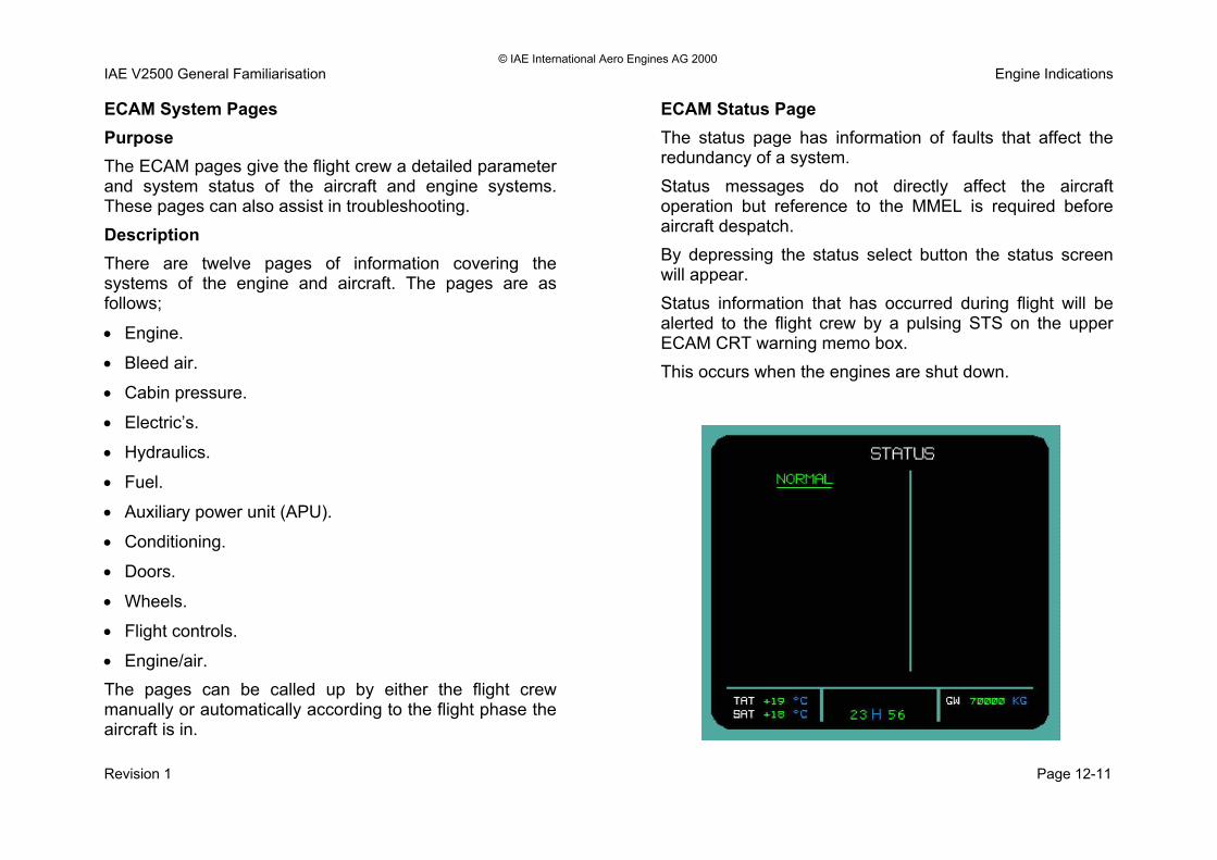
© IAE International Aero Engines AG 2000 IAE V2500 General Familiarisation Engine Indications ECAM System Pages Purpose The ECAM pages give the flight crew a detailed parameter and system status of the aircraft and engine systems. These pages can also assist in troubleshooting. Description There are twelve pages of information covering the systems of the engine and aircraft. The pages are as follows;
• Engine.
• Bleed air.
• Cabin pressure.
• Electric’s.
• Hydraulics.
• Fuel.
• Auxiliary power unit (APU).
• Conditioning.
• Doors.
• Wheels.
• Flight controls.
• Engine/air. The pages can be called up by either the flight crew manually or automatically according to the flight phase the aircraft is in.
ECAM Status Page The status page has information of faults that affect the redundancy of a system. Status messages do not directly affect the aircraft operation but reference to the MMEL is required before aircraft despatch. By depressing the status select button the status screen will appear. Status information that has occurred during flight will be alerted to the flight crew by a pulsing STS on the upper ECAM CRT warning memo box. This occurs when the engines are shut down.
Revision 1 Page 12-11

© IAE International Aero Engines AG 2000 IAE V2500 General Familiarisation Engine Indications
Revision 1 Page 12-12

© IAE International Aero Engines AG 2000 IAE V2500 General Familiarisation Engine Indications Flight Deck Centre Pedestal The following are some of the Engine related controls and interfaces: 1. Captains Multipurpose Centralised Display Unit
(MCDU) 2. Systems Display Control Panel 3. First Officers Multipurpose Centralised Display Unit
(MCDU) 4. Engine No. 2 Thrust Lever 5. Engine No. 2 Master Switch 6. Ignition Mode Selector Switch 7. Printer 8. Engine No. 1 Thrust Lever 9. Engine No. 1 Master Switch
Revision 1 Page 12-13

© IAE International Aero Engines AG 2000 IAE V2500 General Familiarisation Engine Indications
Revision 1 Page 12-14

© IAE International Aero Engines AG 2000 IAE V2500 General Familiarisation Engine Indications Flight Deck Overhead Panel The following are some of the Engine related interfaces found on the Overhead Panel: 1. N1 Mode Selector Switches for No. 1 & No. 2 engine 2. Engine Manual Start Switches for No. 1 & No. 2 engine 3. Engine and Auxiliary Power Unit (APU) Fire Panel 4. FADEC ground power switches for No. 1 & No. 2 engine
Revision 1 Page 12-15

© IAE International Aero Engines AG 2000 IAE V2500 General Familiarisation Engine Indications
Revision 1 Page 12-16

© IAE International Aero Engines AG 2000 IAE V2500 General Familiarisation Engine Indications Shaft Speed Indicating System Purpose The speed indicating system provides signals of;
• N1 shaft speed.
• N2 shaft speed. The indications are used for ;
• The ECAM CRT display.
• EEC control. A dedicated signal is used for trim balancing purposes. Location The N1 speed sensors are located in the front bearing chamber mounted on the no.2 bearing support. The N2 speed indication is the output signals from the dedicated generator. Description The speed indicating description is as follows; N1 System The N1 indication is supplied by three pulse probes. The pulse probes operate by monitoring the passage of a phonic wheel. The phonic wheel passage across the pulse probe generates an output signal relative to a percentage of a revolution.
Hence if the phonic wheel has 60 teeth then 60 pulses represents a complete revolution of the N1 shaft. N2 System The N2 indication is supplied by a dual output signal from channel B of the dedicated generator.
• An output goes to the channel B side of the EEC.
• An output goes to the EVMU. Fan Trim Balance The fan trim balance probe is located in the same place as the speed pulse probes. This probe supplies a dedicated signal for monitoring of LP system unbalance. The probe is also different from the speed probes. It cannot be utilised to give N1 speed indication. The pulse probe monitors a datum tooth of the phonic wheel. This tooth is in line with the no.1 fan blade.
Revision 1 Page 12-17

© IAE International Aero Engines AG 2000 IAE V2500 General Familiarisation Engine Indications
Revision 1 Page 12-18

© IAE International Aero Engines AG 2000 IAE V2500 General Familiarisation Engine Indications N1Speed Indicating System Operation The probes comprise of two pole pieces, a permanent magnet, and a coil wound on to one of the pole pieces. The pole pieces span two teeth of the phonic wheel. The phonic wheel is an integral part of the fan stub-shaft and has 60 teeth. As the shaft rotates and the teeth of the phonic wheel pass the pole pieces and a voltage pulse is produced in the winding. The number of pulses produced is directly proportional to the speed of the shaft. This signal is passed to the EEC and is used to display N1 speed on the flight deck and also for the engine control circuits as required. Trim Balance Probe The signal from this probe is only used during trim balance operations and provides the phase relationship between any out of balance forces present and a datum position. The trim balance probe senses the passage of one specially modified tooth on the phonic wheel and produces one pulse per revolution.
Revision 1 Page 12-19

© IAE International Aero Engines AG 2000 IAE V2500 General Familiarisation Engine Indications
Revision 1 Page 12-20

© IAE International Aero Engines AG 2000 IAE V2500 General Familiarisation Engine Indications Exhaust Gas Temperature (EGT) Indicating System Purpose EGT is displayed to the flight deck via the ECAM system to give the flight crew an indication of the engine temperature. This allows the engines to be operated within the temperature limitations as advised by IAE. Location The EGT thermocouples are located at the exhaust outlet. The EGT T/C leads come together at a junction box located at BDC of the turbine casing. Description The EGT is measured by 4 thermocouples, which are located in the support struts of the turbine exhaust case (engine station 4.9). The 4 thermocouples are connected to the junction box by a thermocouple harness. The materials used for the thermocouples and harness are;
• Chromel (CR).
• Alumel (AL). An extension harness connects the EGT junction box to channels A and B of the EEC.
Indication The EGT indication appears on the upper ECAM display unit. The ECAM provides the EGT indication; • In analogue dial gauge format. • In digital format. EGT is below 610 deg.c. The actual EGT indication is normally green. EGT is > 610 deg c. The indication pulses and changes colour to amber. EGT is > 635 deg c. • The indication becomes red. • The MASTER WARN light comes on, accompanied by
the repetitive audible chime. The following message appears on the ECAM upper CRT; EGT OVERLIMIT • The maximum value reached is memorised. • A small red line remains positioned on the analogue
scale at that value (max pointer). Note: The small and large nuts that secure the EGT leads to the junction box must torque check and tightened during the A check until further notice. Single and dual channel failures have occurred due to loose EGT securing nuts.
Revision 1 Page 12-21

© IAE International Aero Engines AG 2000 IAE V2500 General Familiarisation Engine Indications
Revision 1 Page 12-22

© IAE International Aero Engines AG 2000 IAE V2500 General Familiarisation Engine Indications P3/T3 Sensor Purpose To give the EEC an input signal of;
• P3 pressure for fuel scheduling and surge detection.
• T3 temperature for trend monitoring. Location The P3/T3 sensor is located on the combustor casing at the one o’clock position. Description The P3/T3 sensor is a dual-purpose aerodynamically shaped probe. It measures the pressure and temperature of the air stream at the inlet of the diffuser case. The resultant data is transmitted to the EEC for control purposes. At the EEC the pressure enters a transducer. The temperature signal is received as a resistance value.
Revision 1 Page 12-23

© IAE International Aero Engines AG 2000 IAE V2500 General Familiarisation Engine Indications
Revision 1 Page 12-24

© IAE International Aero Engines AG 2000 IAE V2500 General Familiarisation Engine Indications Engine Pressure Ratio (EPR) Indicating System Purpose To indicate to the flight deck a parameter that is the representation of engine thrust. Location The main components of the EPR system is the P2/T2 probe and the P 4.9 pressure rakes. They are located; P2/T2 probe in the intake cowl at approximately TDC. P4.9 pressure rakes are in the exhaust duct of the LPT. Description The engine pressure ratio (EPR) is used to set and control the engine thrust EPR. EPR is;
P4.9 P2
P2 is measured by the P2/T2 Probe. P4.9 is measured by a pressure rake. The pressures from these sensors are routed to the EEC. The EEC processes the pressure signals to form actual EPR and transmits the EPR value to the ECAM for display on the upper screen. Each of the two EEC channels carry out this operation independently.
EPR Indications The actual EPR is displayed in green. The display changes to Amber if EPR exceeds limit. The display changes to red, with master caution and single chime if EPR exceeds red line limit (TBD). The associated indications are:
• EPR maximum has a thick amber line.
• EPR limit maximum EPR value corresponding to thrust limit mode, which can be any one of the five conditions that follow;
Take off/go around mode (TO/GA). Flexible take-off mode (FLX). Maximum continuous thrust mode (MCT). Climb mode (CLB). Flex TO Temperature is an assumed temperature entered by the flight crew through the MCDU to the FMS facility. EPR reference is the predicted EPR value according to TRA.
Revision 1 Page 12-25
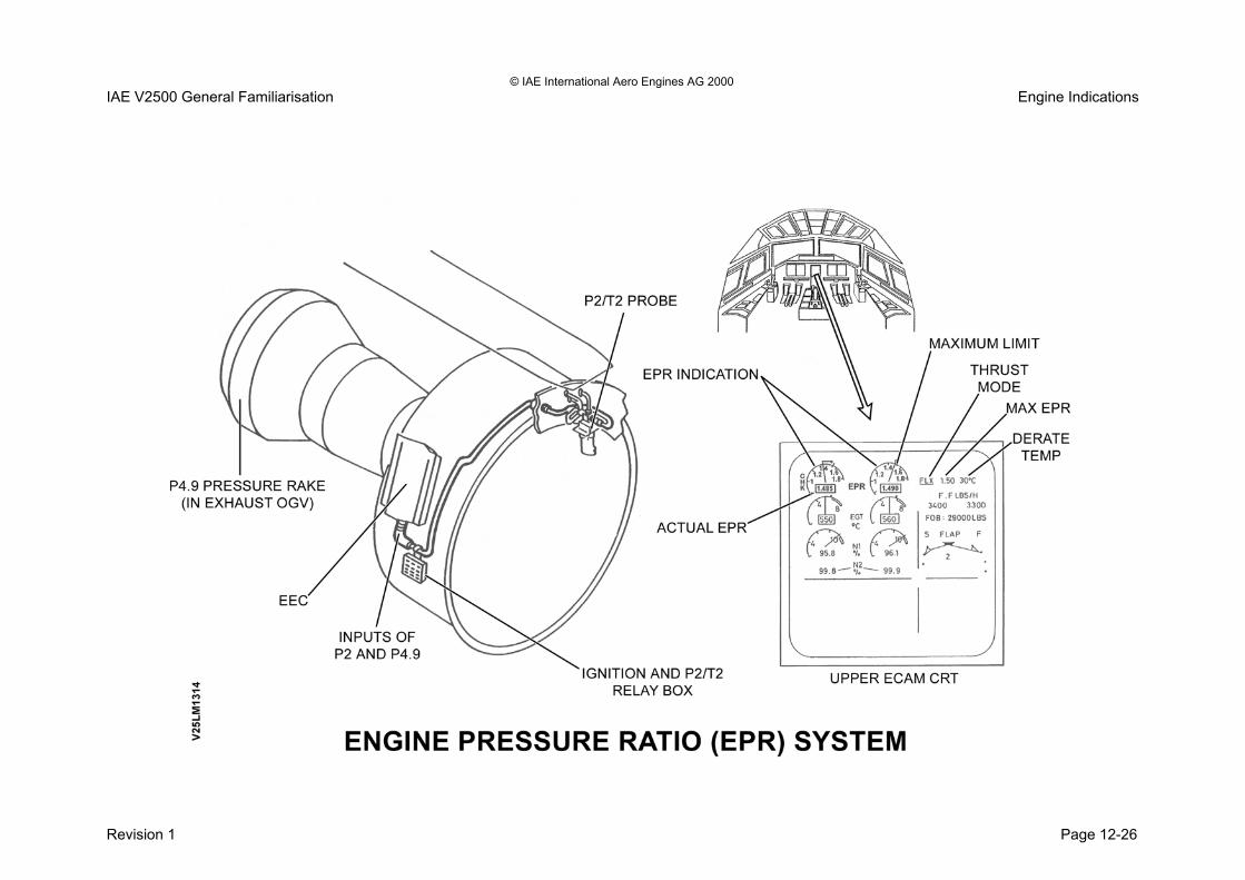
© IAE International Aero Engines AG 2000 IAE V2500 General Familiarisation Engine Indications
Revision 1 Page 12-26

© IAE International Aero Engines AG 2000 IAE V2500 General Familiarisation Engine Indications EPR System P2/T2 Sensor Purpose The P2/T2 sensor is a dual purpose probe which measures the total air temperature and pressure in the inlet air stream. The temperature and pressure signals are fed to the EEC. Location The sensor is installed at the 12 o'clock position in the air inlet cowl. Description The temperature is measured by two platinum resistance elements. Each channel of the EEC monitors one of the elements. The pressure signal is fed to a pressure transducer in the EEC. The sensor is electrically heated to provide anti ice protection. The EEC software corrects any temperature signal errors caused by heating. Note: The probe anti icing heater utilises 115V AC from the aircraft electrical system. Higher thrust engines (V2533) have a longer probe. The relay box on the right hand side of the fan case controls the selection of voltage to the probe heater unit.
EPR System P4.9 Rake Purpose The P4.9 rakes send a pressure signal to the EEC for the EPR system. Location The P4.9 rakes are located in the exhaust OGVs. They are in the 3, 6 and 9 o’clock position. Description The P4.9 pressure rakes send a pressure signal down a common tube to a transducer within the EEC.
Revision 1 Page 12-27

© IAE International Aero Engines AG 2000 IAE V2500 General Familiarisation Engine Indications
Revision 1 Page 12-28

© IAE International Aero Engines AG 2000 IAE V2500 General Familiarisation Engine Indications Engine Vibration Indicating System Purpose The system monitors engine vibration for engine 1 and engine 2. Location The vibration transducer is located on the engine fan case in the 11 o’clock position. Description Monitoring is done by a vibration transducer on each engine fan case. This produces an electrical signal in proportion to the vibration detected and sends it to the engine vibration monitoring unit (EVMU). Two channels come from each engine. The EVMU provides signals of;
• Vibration.
• N1 (LP shaft speed).
• N2 (HP shaft speed). These are displayed on the engine page of the ECAM. The vibration transducer is installed on the fan case at the top left side of the engine. It is attached with bolts and is installed on a mounting plate.
Indications The engine vibration indications are displayed in green on the lower ECAM display unit on the engine and cruise pages. The ECAM display unit receives the information through the ARINC 429 data bus via the SDAC 1 and SDAC 2. If the advisory level is reached, the indication flashes (0.6-sec bright, 0.3-sec normal). If the indication is not available, 2 amber crosses replace the corresponding indication. Note: A5 engines have a dual cable. D5 engines have a single cable.
Revision 1 Page 12-29

© IAE International Aero Engines AG 2000 IAE V2500 General Familiarisation Engine Indications
Revision 1 Page 12-30


SECTION 13
ENGINE STARTING AND IGNITION

© IAE International Aero Engines AG 2000 IAE V2500 General Familiarisation Engine Starting and Ignition System Engine Starting and Ignition System Purpose The engine starting system is to allow the engine to achieve minimum power conditions (low idle). The engine requires assistance to achieve this condition. The engine ignition system provides the electrical spark that is required to ignite the fuel air mix in the combustor. The ignition system is used for; • Engine starting on ground and in flight. • Prevention of a flame out by providing a continuous
spark during engine running when the aircraft is flying through a heavy rainstorm for example.
Description The system comprises of the following; • Pneumatic starter motor. • Starter air control valve. • Dual ignition system. • Pneumatic ducting. • Start control panels on the flight deck for auto starts,
manual starts and starter motor operation. • ECAM indications. Starting of the engine for the Airbus A319, 320 and 321 can be done either; • Manually. • Automatically.
Basic start sequence Whichever method of starting is selected the EEC has control. The start sequence is initiated in the flight deck. Upon selection for engine start an electrical signal is sent to open the starting air valve. The starting air valve opens and admits the air supply into the starter motor. The starter motor rotates the high speed external gearbox that in turn rotates the radial drive shaft (tower shaft) that in turn rotates the HP system (N2). As the HP system gathers momentum of rotation the LP system starts to rotate. • At 10% N2 the dedicated generator comes on line. • At 16% N2 the ignition system becomes live. • At 18% N2 the FMV opens to admit fuel to the
combustor. At 43% N2 the starter air valve is deselected. At 50% N2 and above the EEC auto start protection is cancelled. At approximately 60% N2 the engine is at minimum power conditions (low idle). Note; Above 50% N2 the command for engine shut down is done from the master lever only.
Revision 1 Page 13-1

© IAE International Aero Engines AG 2000 IAE V2500 General Familiarisation Engine Starting and Ignition System
Revision 1 Page 13-2

© IAE International Aero Engines AG 2000 IAE V2500 General Familiarisation Engine Starting and Ignition System Starter Air Duct Purpose To provide a means of supplying air to the starter motor. Location The starter air duct is located on the right hand side of the engine fan casing (intermediate module). Description Air supplies for the pneumatic starter motor may be supplied from;
• The aircraft APU.
• Cross bleed from the other engine if already running.
• Ground starter trolley. Minimum duct pressure for starting should be between 30 and 40 psi. All ducting in the system is designed for high pressure and high temperature operation. Gimbal joints are incorporated to permit working movement. E-type seals located between all mating flanges prevent air leakage, mating flanges are secured by Vee-band coupling clamps.
Revision 1 Page 13-3

© IAE International Aero Engines AG 2000 IAE V2500 General Familiarisation Engine Starting and Ignition System
Revision 1 Page 13-4

© IAE International Aero Engines AG 2000 IAE V2500 General Familiarisation Engine Starting and Ignition System Starter Air Control Valve Purpose The starter air control valve is designed to control the admittance of air to the starter motor. The valve is commanded from the flight deck via the EEC. Location The starter air control valve is located on the right hand side of the engine fan casing (intermediate module). Description The starter air control valve consists of the following;
• Butterfly valve for airflow control.
• Pneumatically operated.
• Microswitch position indication for valve positional status.
• Air filter to prevent valve operating mechanisms from contamination.
• Failsafe position of the valve is closed.
• Provision of a manual override for abnormal start attempts.
The starter air control valve is a pneumatically operated, electrically controlled shut-off valve. The valve is positioned on the lower right hand side of the engine fan casing.
The starter air valve controls the airflow from the air ducting to the starter motor. The start valve basically comprises a butterfly type valve housed in a cylindrical valve body with in line flanged end connectors, an actuator, a solenoid valve and a pressure controller. Manual operation The starter air valve can be opened/closed manually using a 0.375 in square drive. Access is through a panel in the right hand side fan cowl door. A valve position indicator is provided on the valve body. A micro switch provides valve position feed back information to the EEC.
Revision 1 Page 13-5

© IAE International Aero Engines AG 2000 IAE V2500 General Familiarisation Engine Starting and Ignition System
Revision 1 Page 13-6

© IAE International Aero Engines AG 2000 IAE V2500 General Familiarisation Engine Starting and Ignition System Starter Air Valve Operation The starter air valve operation for opening and closing is as follows; Engine shutdown With no pneumatic air supply available the valve is spring loaded to the closed position. Valve opening Air upstream of the butterfly valve is filtered and routed through an orifice in the solenoid valve. Air upstream of the orifice is also admitted to the smaller piston of the double acting actuator. When the solenoid is energised the ball valve opens to admit air to the larger piston whilst simultaneously closing the vent port. The air acting on the larger piston overcomes the combined force of upstream air pressure acting on the smaller piston and the actuator spring. Movement of the actuator is translated through the linkage to rotate the butterfly valve towards the open position.
Valve closing When the solenoid is de-energised, at approximately 6000 rpm (43%) N2, the ball valve closes and air acting on the larger piston is vented to atmosphere through the vent. Air pressure and actuator spring pressure acting on the smaller piston then closes the butterfly valve. Any loss of air pressure will cause the butterfly valve to close under the action of the actuator spring.
Revision 1 Page 13-7

© IAE International Aero Engines AG 2000 IAE V2500 General Familiarisation Engine Starting and Ignition System
Revision 1 Page 13-8

© IAE International Aero Engines AG 2000 IAE V2500 General Familiarisation Engine Starting and Ignition System Pneumatic Starter Motor Purpose The purpose of the pneumatic starter motor is to provide an initial rotational input to the high speed external gearbox in order to assist the engine to achieve a stable minimum power condition (low idle). Location The starter motor is located on the front face of the high speed external gearbox. Description The starter motor consists of the following;
• Oil filler/level plug.
• Drain plug with a built in magnetic chip detector.
• QAD devices to allow for ease of maintenance. The starter motor gears and bearings are lubricated by an integral lubrication system. A quick attach/disconnect adapter (QAD) attaches the starter motor to the external gearbox. A quick detach Vee clamp connects the starter motor to the adapter. Note; There are two standards of starter motor available for the V2500 powerplant. The current being the synchronous clutch engagement unit. The synchronous clutch allows for smoother crash engagements thus reducing the wear and damage caused by such operations.
Revision 1 Page 13-9

© IAE International Aero Engines AG 2000 IAE V2500 General Familiarisation Engine Starting and Ignition System
Revision 1 Page 13-10

© IAE International Aero Engines AG 2000 IAE V2500 General Familiarisation Engine Starting and Ignition System Starter Motor Operation The starter is a pneumatically driven turbine unit that accelerates the HP rotor to the required speed for engine starting. The starter comprises of the following;
• A single stage turbine.
• A reduction gear train.
• A clutch and an output drive shaft. These are all housed within a case incorporating an air inlet and exhaust. Compressed air enters the starter, impinges on the turbine blades to rotate the turbine, and leaves through the air exhaust. The reduction gear train converts the high speed, low torque rotation of the turbine to low speed, high torque rotation of the gear train hub. The ratchet teeth of the gear hub engage the pawls of the output drive shaft to transmit drive to the external gearbox, which in turn accelerates the engine HP compressor rotor assembly. When the air supply to the starter is cut off, the pawls overrun the gear train hub ratchet teeth allowing the turbine to coast to a stop. The engine HP turbine compressor assembly, the external gearbox and starter output drive shaft continue to rotate.
When the starter output drive shaft rotational speed increases above a predetermined rpm, Centrifugal force overcomes the tension of the clutch leaf springs, allowing the pawls to be pulled clear of the gear hub ratchet teeth to disengage the output drive shaft from the turbine.
Revision 1 Page 13-11

© IAE International Aero Engines AG 2000 IAE V2500 General Familiarisation Engine Starting and Ignition System
Revision 1 Page 13-12

© IAE International Aero Engines AG 2000 IAE V2500 General Familiarisation Engine Starting and Ignition System Engine Ignition System Purpose The ignition system is designed to provide the means of igniting the air/fuel mix in the combustor. Location The ignition system units are located in the following positions;
• The relay box is located on the right hand side of the engine fan case.
• The high energy ignition units (HEIUs) are located on the right hand side of the core engine. Mounted on the HPC casing.
• The igniter plugs are located on the combustion diffuser casing at fuel spray nozzle positions no. 7 and 8.
Description Two independent ignition systems are provided. The system is made up of the following units;
• Ignition relay box.
• Two ignition exciter units.
• Two igniter plugs.
• Two air cooled HT ignition connector leads.
The ignition system can operate in various modes. These modes are as follows; Dual igniter select;
• All in flight starts.
• Manual start attempts.
• Continuous ignition. Single alternate igniter select;
• Auto starts. Continuous ignition select;
• Engine anti ice.
• Take off.
• Approach.
• Landing.
• EEC failure. Continuous ignition may also be selected manually. The ignition exciters provide approximately 22.26 Kv and the igniter discharge rate is 1.5/2.5 sparks per second. Test Operation of the ignition system can be checked on the ground, with the engine shut down, through the maintenance menu mode of the CFDS.
Revision 1 Page 13-13

© IAE International Aero Engines AG 2000 IAE V2500 General Familiarisation Engine Starting and Ignition System
Revision 1 Page 13-14

© IAE International Aero Engines AG 2000 IAE V2500 General Familiarisation Engine Starting and Ignition System Ignition Relay Box Purpose Used for connection and the isolation of the high energy ignition units. Location The relay box is located on the right hand side of the engine fan casing. Description The ignition system utilises 115V AC supplied from the AC 115V normal and standby bus bars to the relay box. The 115V relays, which are used to connect/isolate the supplies are located in the relay box and are controlled by signals from the EEC. Note; The same relay box also houses the relay that controls the 115V AC supplies for P2/T2 probe heating.
Revision 1 Page 13-15

© IAE International Aero Engines AG 2000 IAE V2500 General Familiarisation Engine Starting and Ignition System
Revision 1 Page 13-16

© IAE International Aero Engines AG 2000 IAE V2500 General Familiarisation Engine Starting and Ignition System Engine Starting Electrical Control Engine Interface Unit (EIU) Purpose The EIU is an interface concentrator between the aircraft and FADEC system. Location The EIU is located in the avionics bay. Description There are two engine interface units (EIU’s), one for each engine. The EIU is an interface concentrator between the aircraft and FADEC system. The EIU main functions are;
• To concentrate data from the flight deck panels.
• To ensure the segregation of the two engines.
• To provide the EEC with electrical power supply.
• To give the necessary logic and information between the engine and the aircraft systems.
• Receives discrete electrical signals from the cockpit. Digitises these signals and transmits them to the EEC. Also sends discrete signals to close air conditioning pack flow valves and increase the airflow from the APU if required.
Electronic Engine Control (EEC) Purpose To provide electronic signals for FADEC system unit control. Location The EEC is located on the engine fan casing right hand side. Description The EEC is the heart of the FADEC system and has control of the FADEC system components and constantly monitors their performance. The EEC will make adjustments where necessary to optimise the operation of the engine. During the starting of the engine the EEC generates the pneumatic starter valve opening/closing signal in respect of control switch selection (rotary selector, master lever, ‘MAN START’ push button switch) and N2 speed signal. The EEC will send any warning or caution message to the flight warning computer (FWC). The FWC will send this to the display management computer (DMC) for indication on the ECAM upper or lower CRT.
Revision 1 Page 13-17

© IAE International Aero Engines AG 2000 IAE V2500 General Familiarisation Engine Starting and Ignition System
Revision 1 Page 13-18

© IAE International Aero Engines AG 2000 IAE V2500 General Familiarisation Engine Starting and Ignition System Engine Operation Purpose The purpose of engine operation on the ground is to validate non FADEC detected faults (mechanical failures) and to prove the integrity of an LRU or system after maintenance has been carried out. Flight deck The flight deck is where the engines are operated from. There are two panels utilised for starting the engine. These panels are;
• The auto mode select panel (auto starts).
• The alternate mode select panel (manual starts). Auto mode select panel The auto mode select panel has the following;
• Two main engine master switches.
• Rotary switch. The engine master switches have two positions;
• Cut off.
• On. These switches activate the start air valve and the FMU, via the EIU and EEC, when in the auto mode. These switches activate the FMU, via the EIU and EEC, when in the alternate (manual) mode.
The rotary switch has three positions;
• Crank.
• Mode norm.
• Ign/start. The crank position allows operation of the starter motor only. The mode norm sets the ignition to auto function, for example when anti icing is selected the ignition comes on to a continuous operation. The ign/start allows the engine to be started. This switch must be in the ign/start position before selecting the master levers to the on position. Alternate mode (manual start pamel). The alternate mode select panel allows the engine to be started in the non auto function or manual mode. Note: The EEC software has a fuel flow reduction capability upon the detection of a stall. This is known as fuel depulse. The depulse logic is designed to assist the engine in recovery from a stall during starting.
Revision 1 Page 13-19

© IAE International Aero Engines AG 2000 IAE V2500 General Familiarisation Engine Starting and Ignition System
Revision 1 Page 13-20

© IAE International Aero Engines AG 2000 IAE V2500 General Familiarisation Engine Starting and Ignition System Safety Zones During run up operations, extreme care should be exercised when operating the engines Refer to the diagram below, which illustrates the inlet suction hazard areas for the conditions at idle and take-off thrust. .
Revision 1 Page 13-21

© IAE International Aero Engines AG 2000 IAE V2500 General Familiarisation Engine Starting and Ignition System
Revision 1 Page 13-22

© IAE International Aero Engines AG 2000 IAE V2500 General Familiarisation Engine Starting and Ignition System Safety Zones - Jet Wake Hazard Areas During run up operations, extreme care should be exercised when operating the engines. Refer to the diagram below, which illustrates the jet wake hazard areas for the conditions at idle and take-off thrust. Noise Danger Areas All persons working near the engine while it operates must wear ear protection. Loud noise from the engine can cause temporary or permanent damage to the ears.
Revision 1 Page 13-23

© IAE International Aero Engines AG 2000 IAE V2500 General Familiarisation Engine Starting and Ignition System
Revision 1 Page 13-24


SECTION 14
THRUST REVERSER SYSTEM

© IAE International Aero Engines AG 2000 IAE V2500 General Familiarisation Thrust Reverser System Thrust Reverser System Introduction Purpose The thrust reverser is designed to assist the aircraft in decelerating quickly and safely upon landing. It also assists deceleration during an aborted takeoff. Location The thrust reverser is an integral part of the C duct assembly. The C duct assembly is mounted to the aircraft strut by four hinged brackets located at the top of the C ducts. They are held in the closed position by six latch locks located at the bottom of the C ducts. Description The reverser is a translating sleeve type system. It directs the fan air rearwards for normal forward thrust or forwards for thrust reverse. When the thrust reverser system is in the stow position the fan air exhausts at the common nozzle. This produces forward thrust. When the thrust reverser is deployed four linear motion actuators cause the translating sleeves to move rearwards. This moves the blocker doors from an axial to a radial position in the C duct fan exhaust area. The blocker doors forces the fan air through the cascades in a forward direction. The cascades are exposed whenever the thrust reverser is deployed.
Reverse thrust is selected from the flight deck by the gated reverse thrust levers. The EEC has control over the operation of the thrust reverse system. All signals to and from the thrust reverser are through the EIU and EEC. Thrust reverser system features Electronic control. Hydraulic actuation system. Positional information feedback. Actuator lock position sensors and feedback. Electronic safety locks. Automatic re-stow system. Manual deployment and stow capability for maintenance. Manual lockout to allow aircraft to be despatched with an inoperative thrust reverser.
Revision 1 Page 14-1

© IAE International Aero Engines AG 2000 IAE V2500 General Familiarisation Thrust Reverser System
Revision 1 Page 14-2
DET
V250
262
V2500 THRUST REVERSER SYSTEM V2500 THRUST REVERSER SYSTEM
© IAE International Aero Engines AG 2000 IAE V2500 General Familiarisation Thrust Reverser System
Page 14-3 Revision 1
• EIU inhibit relays for un-commanded in-flight deployment.
Thrust Reverser Assembly When the translating sleeves are in the forward thrust position the path of the fan bypass air is in the normal forward thrust. Rearward movement of the translating sleeves unveils the cascade deflectors and moves the blocker flaps from an axial to a radial position. This blocks the fan stream airflow and forces the fan efflux through the cascade deflectors. Methods of deployment The thrust reverser can be deployed in one of two methods; • Using the engine/aircraft hydraulic system. Moving the
thrust reverse select levers that are mounted on the main forward levers does selection.
• Manual input by two hand turning points for maintenance purposes.
Safety features The thrust reverse system operation is controlled by the engine electronic control (EEC). The following are EEC controlled functions of the thrust reverse system. The thrust reverse system incorporates a double lock safety system to protect against inadvertent deployment. They are; • Landing gear control unit (LGCU). • Lock sensors on the locking actuators.
• Shut off valve that is signalled to operate from the
SEC. • The thrust reverser also has a system that will return
the engine thrust to idle should the thrust reverse system inadvertently deploy.
• Auto re-stow is a system that is designed to stow the thrust reverser when an un-commanded deployment is detected.
Indications ECAM indications for fault annunciation of the thrust reverser system status are done by use of proximity sensors, relay select status, hydraulic system pressures and LVDT feedback signals. The locking actuator sensors detect unlocked conditions and the LVDT detects transient and deployed conditions. The signals are relayed from the EEC to the EIU and then to the ECAM screens.

© IAE International Aero Engines AG 2000 IAE V2500 General Familiarisation Thrust Reverser System
Revision 1 Page 14-4

© IAE International Aero Engines AG 2000 IAE V2500 General Familiarisation Thrust Reverser System
Page 14-5 Revision 1 In the flight deck this unlocked condition is identified as an
amber coloured REV caption on the EPR indicating gauge. Operation Thrust reverse is selected from the flight deck by pulling up on the thrust reverse select levers. The select levers are mounted on the front side of the main thrust levers. The thrust levers have a gated feature that allows thrust operation by the throttles in one direction only. The EEC has control of the thrust reverse system operation for deploy and stow. The EIU inhibit relay controls the DCV power signal for the control solenoid from the EEC to the DCV. Deploy Pulling up on the thrust reverse lever in the flight deck will send a signal for thrust reverse select to the EEC. This will also put the main throttles in the reverse thrust quadrant. The EEC will look for the following conditions before thrust reverse will be allowed; • The EEC will check that the aircraft is on the ground by
checking the LGCU signal of the aircraft computers. • The EEC will check that the engine is running by means
of a N2 signal. • The EEC cannot deploy the thrust reverser until the EIU
inhibit relay is active. • SEC control signal for the shut off valve. The hydraulic isolation valve solenoid and the directional control valve solenoid will both be energised for a deploy condition. This will admit high pressure hydraulic fluid to the stow and deploy sides of the thrust reverse system. The lower locking actuators will unlock and the EEC will see a signal from the proximity sensor of reverser system unlocked.
When the translating sleeves have moved to 78% of the full deploy position the amber REV indication will change to a green REV indication. When green REV is indicated the full reverse thrust power is available to the flight crew. Stow To stow the thrust reverse system the flight crew will return the throttles to the idle detent position and select levers to the down position. This will put the throttles back to the forward thrust quadrant. The hydraulic isolation valve solenoid is energised and the directional control valve solenoid is de-energised for a stow condition. This leaves high pressure hydraulic fluid present on the stow side of the system. As the translating sleeves move from deploy back to stow the flight deck indication will change from green to amber on the REV indication. When the thrust reverser has reached the fully stowed position the amber REV will go and the EPR gauge will return to normal indication. This will indicate that the thrust reverser is fully stowed and locked.

© IAE International Aero Engines AG 2000 IAE V2500 General Familiarisation Thrust Reverser System
Revision 1 Page 14.6

© IAE International Aero Engines AG 2000 IAE V2500 General Familiarisation Thrust Reverser System Controls and Indications Thrust reverse is selected from the flight deck by use of latching selector levers that are mounted on the main throttle control levers. Controls Pulling the levers upwards will initiate the sequence of events that will deploy the reverser system. The EEC, in conjunction with the EIU, controls the deployment and stowing of the reverser system. The levers move into the thrust reverse quadrant therefor while in this position throttle movement is only possible in the thrust reverse mode. Movement towards the maximum throttle stop for thrust reverse is possible but the engine will only accelerate when the EEC has feedback of the translating sleeve status. The translating sleeve must be beyond 78% of the fully deployed position. Stowing the thrust reverser requires the latching select levers to be pushed down and the main throttles will revert back to normal forward thrust. This will also stow the reverser system. Indications The thrust reverser system indications appear on the ECAM CRTs. The EPR indication is used to display the status of the thrust reverser.
Normal indication Thrust reverser stowed and locked.
REV in colour amber Thrust reverser unlocked and in transit.
REV in colour green Thrust reverser deployed. Thrust reverser indications of non-normal conditions will be indicated to the ECAM screens in the form of a message. The following are the associated ECAM messages that appear to the ECAM screens;
• Reverse Unlocked.
• Reverser Fault.
• Rev pressurised.
• Rev Switch Fault. By entering the CFDS screens the faults can be interpreted to pinpoint the location.
Revision 1 Page 14.7

© IAE International Aero Engines AG 2000 IAE V2500 General Familiarisation Thrust Reverser System
Revision 1 Page 14-8

© IAE International Aero Engines AG 2000 IAE V2500 General Familiarisation Thrust Reverser System Hydraulic System The hydraulic system provides the force required to move the translating sleeves for both deploy and stow conditions. The hydraulic system comprises of the following;
• Linear motion actuators.
• Flex shaft.
• Hydraulic control unit comprising of a HIV and DCV. Linear Motion Actuators There are four linear motion actuators per C duct set. The two upper actuators are non-locking and incorporate LVDT’s for feedback to the EEC. The two lower actuators are locking they incorporate proximity sensors to give indication to the EEC of lock and unlock conditions. Flex shaft The four linear motion actuators are kept in synchronisation movement by flexible shafts that have a high torsion resistance. Hydraulic Control Unit The hydraulic control unit comprises of the following items;
• Hydraulic isolation valve (HIV).
• Directional control valve (DCV).
The HIV controls the presence of high pressure hydraulic fluid in the thrust reverser system. The energising of a control solenoid valve controls this valve. For stow and deploy conditions this valve must be energised. The DCV controls the flow direction of the high pressure hydraulic fluid once it is in the thrust reverser system.
• The DCV will direct the high pressure hydraulic fluid to the stow and deploy sides of the system for deploy conditions.
• The DCV will direct the high pressure hydraulic fluid to the stow side of the system for stow conditions.
Revision 1 Page 14-9

© IAE International Aero Engines AG 2000 IAE V2500 General Familiarisation Thrust Reverser System
Revision 1 Page 14-10

© IAE International Aero Engines AG 2000 IAE V2500 General Familiarisation Thrust Reverser System Hydraulic Control Unit Purpose The hydraulic control unit (HCU) is designed to control the safe passage of the high pressure hydraulic fluid to the thrust reverser system. Location The HCU is located between the top of the engine fan case and the aircraft strut. Access is gained by opening the left hand side fan cowl door. Description The HCU is a self contained LRU designed to control the flow of high pressure hydraulic fluid. The EEC and EIU has control over the HCU control solenoids. When the EEC detects a demand for thrust reverse operation both EEC and EIU will signal the HCU control solenoids. The HCU has the following features;
• A hydraulic isolation valve (HIV) which controls the flow of high pressure hydraulic fluid into the thrust reverser system. The HIV function is controlled by a control solenoid valve.
• A directional control valve (DCV) which controls the direction of flow of the high pressure hydraulic fluid to either the deploy or stow sides of the system. The DCV function is controlled by a control solenoid valve.
• A pressure switch to feedback system pressure status to the EEC.
• A filter with a clog indicator that gives a visual indication of the filter condition when it becomes contaminated.
• A bleed valve.
• Provision for locking out the valve operation for maintenance and flight.
Revision 1 Page 14-11

© IAE International Aero Engines AG 2000 IAE V2500 General Familiarisation Thrust Reverser System
Revision 1 Page 14-12

© IAE International Aero Engines AG 2000 IAE V2500 General Familiarisation Thrust Reverser System Hydraulic Control Unit Operation Deploy When the thrust reverser select levers are moved to the up position the EEC detects that the thrust reverser system is required. • The EEC has selection control over the HIV. • The EIU has selection control over the DCV. The HIV control solenoid will be energised. This moves a lock-pin away from the pilot valve chamber orifice. High pressure hydraulic fluid enters the left hand side of the chamber and forces the pilot valve to move to the right. The pilot valve moves against a spring that exerts a pressure on the right hand side of the pilot valve. The pilot valve recess moves in line with the hydraulic fluid supply tube. This admits high pressure fluid into the thrust reverse system and initially to the stow side of the system. The pressure switch moves to the high pressure indicating position. The DCV control solenoid will be energised. This moves a lockpin away from the pilot valve chamber orifice. High pressure hydraulic fluid enters the left hand side of the chamber and forces the pilot valve to move to the right. The pilot valve moves against a spring that exerts a pressure on the right hand side of the pilot valve. The pilot valve recess moves in line with the hydraulic fluid supply tube. This admits high pressure fluid into the thrust reverse system deploy side of the system. There is now pressure present in both the stow and deploy sides of the system.
The restrictors in the deploy supply tube to the DCV delay the pressure build up to the deploy side so the pressure present on the stow side can push the locking actuators towards the stow. This releases the pressure acting on the tine locking mechanism. Stow To stow the thrust reverser the select levers are moved to the down position. • The EEC has selection control over the HIV. • The EIU has selection control over the DCV. The DCV control solenoid is de-energised. The pilot valve moves to the right due to spring pressure alone. This leaves high pressure hydraulic fluid present in the stow side of the system. When the thrust reverser system has fully stowed the EEC will sense this by a feedback signal coming from the unlock sensors. The EEC will then de-energise the HIV control solenoid. The control solenoid pilot valve will move to the right due to spring pressure alone and the high pressure hydraulic fluid is cut off from the thrust reverser system. HIV Deactivation The deactivating lever prevents the HIV pilot valve from moving. This prevents high pressure hydraulic fluid from entering the thrust reverser system.
Revision 1 Page 14-13

© IAE International Aero Engines AG 2000 IAE V2500 General Familiarisation Thrust Reverser System
Revision 1 Page 14-14

© IAE International Aero Engines AG 2000 IAE V2500 General Familiarisation Thrust Reverser System Lower Locking Actuators Purpose The hydraulic actuators in general control the movement of the translating sleeves. The lower locking actuators incorporate a locking mechanism which gives;
• A feedback signal to the EEC of actuator locked or unlocked.
• A means of preventing the translating sleeves from un-commanded movement.
Location The lower locking actuators are located in the thrust reverser C duct units at the lower positions. Description The actuators in general control the movement of the translating sleeves in a linear motion. The lower actuators on either thrust reverser C duct have a locking mechanism incorporated in the design. The locking mechanism adds to the safety of the system. The lower locking actuators incorporate the following features;
• Hydraulically operated linear motion actuators.
• A locking mechanism called a tine lock. This can only be unlocked when hydraulic pressure is present in the system.
• A linear motion actuator with pressure surfaces on either side of the pressure plate.
• An acme screw thread that rotates a worm gear.
• A worm wheel that rotates the flex shafts.
• A manual unlocking feature for maintenance purposes.
Revision 1 Page 14-15

© IAE International Aero Engines AG 2000 IAE V2500 General Familiarisation Thrust Reverser System
Revision 1 Page 14-16

© IAE International Aero Engines AG 2000 IAE V2500 General Familiarisation Thrust Reverser System Lower Locking Actuators Operation Deploy The EEC will energise the HIV and DCV control solenoids which allows high pressure hydraulic fluid to be present in the thrust reverser system. This is on the stow and deploy sides. The restrictor in the pressure feed tube to the deploy side delays the deploy pressure build up enough to allow the stow pressure to initially push the actuator piston towards the stow direction. This releases the lock pressure on the tine locking mechanism. The unlock sleeve is then pushed towards the right of the tine lock. With the locking sleeve clear of the tine lock the tine lock flexible spring type fingers are free to flex. When the locking sleeve moves a lever assembly also moves. The lever assembly is linked to the external area of the actuator. The lever has a target attached to it.
• When the actuator is at stow the target is in line with the proximity sensor.
• When the actuator is at deploy the target is away from the proximity sensor.
The EEC detects these conditions. High pressure fluid being present in both sides of the system forces the actuator to move towards the deploy direction. This bias of movement exists because the surface area of the deploy side of the pressure plate is greater that the surface area of the stow side.
Stow To stow the thrust reverser the high pressure fluid present on the deploy side of the system must be reduced to tank pressure and ported back to the hydraulic reservoir of the aircraft. The EEC will de-energise the DCV control solenoid and this will leave high pressure hydraulic fluid present on the stow side of the system. The actuator will now move in the stow direction. The head end of the actuator engages into the tine lock. The locking sleeve will move into position to immobilise the tine lock by spring pressure. As the locking sleeve moves to the lock position the target on the unlock indicator moves in line with the proximity sensor. The EEC detects this and sees that the thrust reverser system is stowed.
Revision 1 Page 14-17

© IAE International Aero Engines AG 2000 IAE V2500 General Familiarisation Thrust Reverser System
Revision 1 Page 14-18

© IAE International Aero Engines AG 2000 IAE V2500 General Familiarisation Thrust Reverser System Upper Non Locking Actuators Description The hydraulic actuators in general control the movement of the translating sleeves. The upper non locking actuators incorporate a linear variable displacement transducer (LVDT) that feeds back translating sleeve status of translation and deployment. The actuators operate in the same manner as the locking actuators.
• For deployment the high pressure hydraulic fluid is present on both sides of the system.
• For stowing the high pressure hydraulic fluid is present on the stow side of the system only.
The LVDT monitors the movement of the translating sleeves and feeds back the signals to the EEC. This is done to tell the EEC that the translating sleeves are in transit and when 78% of travel towards the deploy has been achieved.
Revision 1 Page 14-19

© IAE International Aero Engines AG 2000 IAE V2500 General Familiarisation Thrust Reverser System
Revision 1 Page 14-20

© IAE International Aero Engines AG 2000 IAE V2500 General Familiarisation Thrust Reverser System Shut Off Valve Purpose To give additional safety to un-commanded deployments of the thrust reverser. This is known as the third lock of safety. The shut off valve has a filter assembly installed in line with the valve. Location The shut off valve is located in the aircraft strut at the front. It is behind the HCU. Description The shut off valve has the following features; Control solenoid. Two position valve assembly. Operation The shut off valve operation for opening and closing relies upon the signals from the spoilers and elevators computer (SEC). Pulling up the thrust reverse select levers will signal the SEC to open the shut off valve. The SEC sends a signal to the shut off valve relay. The relay energises the solenoid and opens the shut off valve. The high pressure hydraulic fluid now flows towards the HCU. To close the shut off valve the selection of thrust reverse levers must be in the forward thrust position.
Manual Bypass Non Return valve Purpose For normal thrust reverser operation provides a one way directional flow for the hydraulic fluid. For maintenance purposes it allows the flow of hydraulic fluid easier when manual deployment and stow of the thrust reverser is required. Location The manual bypass valve is located in the aircraft strut just behind the shut off valve. Description The manual bypass non return valve allows the flow of hydraulic fluid in one direction only. There is a very hard spring loaded valve inside that is difficult to unseat when carrying out manual operations of the thrust reverser system. The bypass handle allows the valve to become unseated for maintenance operations only. Access to the bypass valve is through an access panel located on the left hand side of the aircraft strut.
Revision 1 Page 14-21

© IAE International Aero Engines AG 2000 IAE V2500 General Familiarisation Thrust Reverser System
Revision 1 Page 14-22

© IAE International Aero Engines AG 2000 IAE V2500 General Familiarisation Thrust Reverser System Thrust Reverser Flex (Synchronisation) Shaft Purpose The flex shaft purpose is to maintain synchronous movement of the actuators. This prevents any one actuator from moving faster than the others. Location The flex shaft is located within the deploy tube system. Description The flex shaft system comprises of the following; T piece housing assembly. This allows the distribution of high pressure hydraulic fluid to both sides of the thrust reverser system. Two flexible tubes. This allows the crossover shaft to link the reverser halves together while allowing the C ducts to be opened. Two rigid tubes. These are found between the upper and lower actuators. They carry hydraulic fluid to the deploy side of the system. Three flexible shafts. These link all the actuators together. Note; The two deploy tubes have a telescopic coupling at one end to permit simple removal and installation without disturbing the actuators.
Revision 1 Page 14-23

© IAE International Aero Engines AG 2000 IAE V2500 General Familiarisation Thrust Reverser System
Revision 1 Page 14-24

© IAE International Aero Engines AG 2000 IAE V2500 General Familiarisation Thrust Reverser System Thrust Reverser Deflector Boxes (Cascades) Purpose The cascades are designed to direct the fan air to provide the reverse thrust for the engine. Location The cascades are located between the inner and outer translating sleeve sleeves. They are mounted on the fixed section of the C ducts. Description There are 16 cascades fitted to the thrust reverser system. The cascades are designed to direct the fan air forwards thus providing for the function of the thrust reverse system. They are designed to direct the fan air away from the ground thus reducing the risk of debris from being blown up and ingested into the engine. They are designed to direct the fan air away from the airframe thus not inducing any unnecessary stress upon the airframe itself.
Revision 1 Page 14-25

© IAE International Aero Engines AG 2000 IAE V2500 General Familiarisation Thrust Reverser System
Revision 1 Page 14-26
© IAE International Aero Engines AG 2000 IAE V2500 General Familiarisation Thrust Reverser System Operation Thrust reverse is selected from the flight deck by pulling up on the thrust reverse select levers. • The EEC has main control of the thrust reverse system
operation for deploy and stow. • The EIU has a inhibit relay that controls the power
supply signal from the EEC to the DCV. • The flight crew have control of reverse thrust power
selection. Deploy Pulling up on the thrust reverse select lever in the flight deck will send a signal for thrust reverse select to the EEC and EIU. This will also put the main throttles in the reverse thrust quadrant. The EEC will look for the following conditions before thrust reverse will be allowed; • The EEC will check that the aircraft is on the ground by
checking the LGCU signal of the aircraft computers. • The EEC will check that the engine is running by means
of a N2 signal. • The EIU will look for the signal from the throttle control
unit for energising of the inhibit relay. • The SEC signal for opening the shut off valve. The hydraulic isolation valve solenoid and the directional control valve solenoid will both be energised for a deploy condition. This will admit high pressure hydraulic fluid to the stow and deploy sides of the thrust reverse system.
The lower locking actuators will unlock and the EEC sees a signal from the proximity sensor of reverser system unlocked. In the flight deck this unlocked condition is identified as an amber coloured REV caption on the EPR indicating gauge. When the translating sleeves have moved to 78% of the full deploy position the amber REV indication will change to a green REV indication. When green REV is indicated the full reverse thrust power is available to the flight crew. Stow To stow the thrust reverse system the flight crew will return the throttles to the idle detent position and select levers to the down position. This will put the throttles back to the forward thrust quadrant. The DCV solenoid will be de-energised as commanded by the EEC via the EIU inhibit relay. This will leave high pressure hydraulic fluid present on the stow side of the reverser system only. As the translating sleeves move from deploy back to stow the flight deck indication will change from green to amber on the REV indication. When the thrust reverser has reached the fully stowed position the amber REV will go and the EPR gauge will return to normal indication. This will indicate that the thrust reverser is fully stowed and locked.
Revision 1 Page 14-27

© IAE International Aero Engines AG 2000 IAE V2500 General Familiarisation Thrust Reverser System
Revision 1 Page 14-28


SECTION 15
TROUBLESHOOTING

© IAE International Aero Engines AG 2000 IAE V2500 General Familiarisation Troubleshooting IAE V2500 Troubleshooting Introduction In order to locate the source of an engine problem both quickly and efficiently, it is essential that the aircraft maintenance engineer is aware of the fundamental approach to troubleshooting required on the Airbus A319/320/321. Having acquired the knowledge of various engine systems functionality and operation during this course, we are now in a position to take the course the natural step forward and discuss the all-important methodology of isolating and identifying the source of a problem. An important tool available to the engineer is the A319/A320/A321 ‘Computer Assisted Aircraft Trouble Shooting’ (CAATS) CD-ROM. This valuable aid provides the user with an enormous amount of detail and information. This manual is revised and issued every three months. Upon receipt and installation of the up-dated version the previous version is automatically overwritten and the previous disc is now no longer valid or useable. The CAATS CD-ROM is password protected for each airline, as it is tailored specifically for each operator’s requirements. Therefore it is essential that the user always access the procedures for their own particular airline. After inserting the correct password the user is presented with the screen shot below.
The most common and straightforward menu selection is ‘Trouble Shooting Procedures’. If the user were to select ‘Trouble Shooting Manual’, this would require the user to insert a known trouble shooting task reference number in order to progress. Unless a procedural task has been already identified during previous investigation activity it will not be practical to use, as its selection would be dependent knowing which system has the fault. Below is a screen shot showing the opening menu options and for the purpose of these training notes we are using ‘British Midland’ as the ‘Log on Airline’.
Revision 1 Page 15-1

© IAE International Aero Engines AG 2000 IAE V2500 General Familiarisation Troubleshooting
Revision 1 Page 15-2

© IAE International Aero Engines AG 2000 IAE V2500 General Familiarisation Troubleshooting IAE V2500 Troubleshooting Introduction continued: Upon selecting ‘Trouble Shooting Procedures’ the user is then presented with the screen shot (fig. 1) shown below.
From this menu it is possible to enter into the trouble shooting process with information derived from a variety of sources: 1. ECAM WARNINGS These are the messages that appeared on the Upper ECAM Screen during operation and show the symptom or system, which has been degraded by a fault.
These are generally of a ‘Class 1’ level which would prevent the aircraft from being dispatched unless the problem and source of the message had been rectified. Check Minimum Equipment List (MEL). 2. ECAM STATUS (Inoperative Systems and
Maintenance Status). The presence of an ECAM Status Message ‘STS’ is automatically displayed on the Upper ECAM Screen during Flight phase 1 (Electrical Power ‘on’ before first engine start) and Flight Phase 10 (When the second engine has been shut down after the flight). It is used to highlight a problem or degradation in the built in redundancy facility of the FADEC System. This feature prevents un-wanted distractions of system degradation being shown to the pilot during the flight. A fault of this nature is dispatchable and the fault can be left un-rectified for up to ten days. Check Minimum Equipment List (MEL) the Status Page can then be selected by pressing the STS button on the Systems Page Select Panel. This will then provide information under the ‘Maintenance’ heading regarding the failure, for example ENG 1(2) FADEC or ENG 1 (2) EIU.
Fig.1 3. LOCAL WARNINGS (Panel Lights and Standby Indicators).
Lists the entry into the Trouble Shooting procedure for given indicated engine related faults. (This has limited use). Information is restricted to ‘Start Air Valves’, ‘Fuel Start Valves’ and Anti-Ice Valve problems.
Revision 1 Page 15-3

© IAE International Aero Engines AG 2000 IAE V2500 General Familiarisation Troubleshooting
STATUS INOP SYSTEM
G+B HYD CAT 3 G RSVR L+R AIL SPLR 1+3+5 L ELEV AP 1+2 ENG 1 REV NORM BREAK NW STEER MAINTENANCE APU AIR COND ENG 1 FADEC
MAX SPD…………………….250/.85 APPR PROC DUAL HYD LO PR -IF BLUE OVHT OUT: -BLUE ELEC PUMP….. ON -LG………………………..GRVTY EXTN -LDG SPD INCRMT………10 KT SLATS SLOW CAT 1 ONLY CANCELLED CAUTION NAV IR 2 FAULT PSI 35 Class 2 Failure of the
Engine Number One’s FADEC System
TAT -5 C SAT -30 C
G.W. 60300KG23H56
STATUS PAGE (LOWER ECAM) Revision 1 Page 15-4

© IAE International Aero Engines AG 2000 IAE V2500 General Familiarisation Troubleshooting IAE V2500 Troubleshooting Introduction continued: 4. FLAGS and ADVISORIES (On ECAM and EFIS
System Pages) Selecting this provides the user with the screen shown Below, see (fig. 2).
By selecting the appropriate system, the user will be presented a complete listing of Flags and Advisories available, related to problems with that particular system. In this example the Engine System. See (fig 3) below.
(fig. 2) (fig.3)
Revision 1 Page 15-5

© IAE International Aero Engines AG 2000 IAE V2500 General Familiarisation Troubleshooting
Revision 1 Page 15-6

© IAE International Aero Engines AG 2000 IAE V2500 General Familiarisation Troubleshooting IAE V2500 Troubleshooting Introduction continued: 5. CREW and MAINTENANCE OBSERVATIONS By selecting this option, the user can relate to what conditions they have seen during the engines operation and link and match the symptoms that to the list provides. Fig 4 below illustrates that if the user types in the main heading for that system, a complete list of all possible observations of faults are produced.
Fig. 5 illustrates the complete listing of, in this example (ATA 73) referenced observations
Fig 5 Fig 4
Revision 1 Page 15-7

© IAE International Aero Engines AG 2000 IAE V2500 General Familiarisation Troubleshooting
Revision 1 Page 15-8

© IAE International Aero Engines AG 2000 IAE V2500 General Familiarisation Troubleshooting IAE V2500 Troubleshooting Introduction continued: 6. CFDS FAULT MESSAGE Centralised Fault Display System (CFDS) This menu selection is one of the most common methods of entering into the Trouble Shooting process. By interpreting the information provided on the Post Flight Report (PFR) and completing the necessary data field boxes, the user can quickly locate the appropriate Trouble Shooting task for this particular systems problem. In this example we have a problem with the Number 2 Engine’s Fuel Heat Management System. This message appeared on the upper ECAM as an ‘ECAM WARNING’ this is a Class 1 failure and is not dispatchable. The CFDS Fault Message is the text contained under the heading ‘FAILURE MESSAGES’ on the Post Flight Report. Again, in this example the Failure Message that is linked to the Upper ECAM ‘ENG 2 FUEL HEAT SYS’ is:
‘FUL DIV RET VLV/HC/EEC2’
This text along with the ATA reference number:
‘73-13-42’ and the Source:
‘EIU2FAD’ is copied into the text boxes as shown on (fig. 6) opposite.
Completing the Class of Failure data can make further refinement of identifying the task. In this case we had an upper ECAM warning message, so in this example we can identify it as a ‘Class 1’ fault.
Fig. 6
Revision 1 Page 15-9

© IAE International Aero Engines AG 2000 IAE V2500 General Familiarisation Troubleshooting
Revision 1 Page 15-10

© IAE International Aero Engines AG 2000 IAE V2500 General Familiarisation Troubleshooting
Revision 1 Page 15-11
IAE V2500 Troubleshooting Introduction continued: 7. None In selecting the menu option of ‘None’ the user is presented with the screen shown below (fig. 7) This requires the insertion of known information in order to refine the search. If in the example shown the user simply types the first two ‘ATA’ digits for engine related problems, which are ‘77’ and then selects ‘Enter’. Then the complete list of failures and associated warnings is produced (fig. 8) opposite.
Fig 7 Fig 8

© IAE International Aero Engines AG 2000
Revision 1 Page 15-12
IAE V2500 General Familiarisation Troubleshooting
Beginning of PFR recording, first engine start + 3 minutes =18:27 End of PFR Recording. 80 knots + 30 seconds = 21:17
GMT (Greenwich Mean Time) =Time when the cockpit warning was displayed. PH = Flight Phase. ATA = Air Transport Association
Note time of ECAM Warning and CFDS Failure Message is the same. (Although there can be up to two minutes difference)
Source = System detecting the fault
POST FLIGHT REPORT

© IAE International Aero Engines AG 2000 IAE V2500 General Familiarisation Troubleshooting E V2500 Troubleshooting Centralised Fault Display System (CFDS) The purpose of the CFDS is to give the maintenance engineers a central maintenance aid to intervene at system or sub-system level from a Multipurpose Centralised Display Unit (MCDU) located on the flight deck. The MCDU allows the engineer to;
• Interrogate a variety of systems using Built in Test Equipment (BITES) for maintenance information.
• To initiate system return to service tests. The detection of the failures, processing and formatting of the failure messages to be displayed is carried out in each systems individual systems BITE. There are two MCDU’s and either the Captain’s or First Officer’s MCDU can be used.
Revision 1 Page 15-13

© IAE International Aero Engines AG 2000 IAE V2500 General Familiarisation Troubleshooting
Revision 1
Alpha Keys
Line Select Keys
Numeric Keys
Brightness Adjust
Annunciators
Function and Mode Keys
Line Select Keys
Page 15-14
MULTIPURPOSE CENTRALISED DISPLAY UNIT (MCDU)
© IAE International Aero Engines AG 2000 IAE V2500 General Familiarisation Troubleshooting Failure Classification and Master Minimum Equipment List (MMEL) The MMEL cannot be used as a Minimum Equipment List (MEL) due to the fact that it is not related to operational requirements, specific operations or airlines particular definitions. The MMEL can be used as a basis for particular operators own MEL. The MEL should be used to establish dispatchability for a particular operation. The MEL does not include those items that are obviously required for aircraft safety, such as wings, engines etc. The MEL does not include those items that do not affect the airworthiness of the aircraft, such as galley equipment, entertainment system etc. Note; All items, which are related to the airworthiness of the aircraft and not included in the list, are automatically required to be operational for each flight. MEL Preamble The MEL is intended to permit operation with inoperative items of equipment for a period of time, until repairs can be accomplished at the earliest opportunity. In order to maintain acceptable levels of safety and reliability the MEL establishes limitations on the duration of and conditions for operation with inoperative equipment. When an item of equipment is discovered to be inoperative, it is reported by making an entry into the Aircraft Maintenance Record/Logbook as prescribed by the Federal Aviation Regulations (FAR).
The item is then either repaired or may be deferred as per the MEL or other approved means acceptable to the Administrator prior to further operation. MEL conditions and limitations do not relieve the operator from determining that the aircraft is in a condition for safe operation with items of equipment inoperative. Federal Aviation Authority (FAA) Repair Intervals All users of an approved MEL, must effect repairs of inoperative systems or components, deferred in accordance with the MEL, at or prior to the repair times established by the following letter designators:
• Category A: To be repaired within the time interval specified in the remarks column of the operator’s approved MEL.
• Category B: To be repaired within three (3) consecutive calendar days (72 hours), excluding the day the malfunction occurred.
• Category C: To be repaired within ten (10) consecutive calendar days), excluding the day the malfunction occurred.
• Category D: To be repaired within one hundred and twenty (120) days), excluding the day the malfunction occurred.
Revision 1 Page 15-15

© IAE International Aero Engines AG 2000 IAE V2500 General Familiarisation Troubleshooting
Revision 1 Page 15-16
Printer MCDU’s
LOCATION OF MCDU’S AND PRINTER

© IAE International Aero Engines AG 2000 IAE V2500 General Familiarisation Troubleshooting Failure Classifications There are three (3) levels of ‘Failure Classifications’ and these are signified by the method of notification of their existence to the Flight Crew or to the Maintenance Engineer during ground operation and testing. Class 1 Failures are indicated, by means of the upper ECAM display or local warnings. Procedures to be followed by the operator to help to ameliorate the problem may also be displayed. Class 2 The operator is informed of a Class 2 failure on the ECAM STATUS page which only shows the system affected by the Class 2 failure. A white ‘STS’ symbol appears on the upper ECAM. Class 3 The operator is not informed of Class 3 failures. Class 3 failures are only accessible through the Centralised Fault Display System (CFDS) via the MCDU in ‘menu mode’
Revision 1 Page 15-17

© IAE International Aero Engines AG 2000 IAE V2500 General Familiarisation Troubleshooting
Revision 1 Page 15-18
CURRENTGROUND FAULTS
FADEC Self TestReverser TestIgnitor TestStart Valve TestP2 T2 Heater Test
500 HOURSClass 3 Faults
UNLIMITEDDESPACTH
DATETIME
ATA CHAPTERCELL NUMBER (1 - 60)
Trouble Shooting Datafrom Stored Faults
Faults storedduring the last leg
Faults storedduring previous 63 legs
FAULT ACRONYM
CELL NUMBERFLIGHT PHASE
FLIGHT LEG
ENGINE PARAMETERSWHEN FAULT RECORDED
'FLIGHT' OPERATION IS DEFINED ASENGINE AT IDLE (PLUS 3 MINUTES)
LAST LEGREPORT
(Screen 7)
PREVIOUS LEGREPORT
GROUNDDATA
(Cells 46 - 60)
FLIGHTDATA
(Cells 1- 45)(Screen 9 &10)
TROUBLESHOOTING(Screen 8)
GROUNDSCANNING
SYSTEM TEST SCHEDULEDMAINT REPORT
CLASS 3(Cells 61-69)
FADEC XXMAIN MENU(Screen 6)
CFDS (Screen 2)
FADEC XX (Screen 6)
ENG (Screen
SYSTEM REPORT TEST
MCDU Main Menu (Screen 1)
Clear Language Message
MCDU SCREEN ROUTEMAP

© IAE International Aero Engines AG 2000 IAE V2500 General Familiarisation Troubleshooting
FAULT CLASS FLIGHT CREW ALERT DISPATCH CONDITIONS
ACTION REQUIRED
Class 1
Visual and Audible Warning (Upper ECAM)
NO GO
or GO IF
or GO
Refer to MEL for details
Class 2
Visual Indication (‘STS’ appears on Upper ECAM) Specific Details (Lower ECAM)
GO
Fault must be recorded and
repaired as per MEL
SMR Scheduled Maintenance Report
No Indication
(CFDS must be interrogated
for details)
No Conditions
Repair at next
'A' Check / 500 hours
Class 3
No Indication
(CFDS must be interrogated
for details)
No Conditions
Time Unlimited Fault
(Should be repaired at
earliest convenient opportunity)
FAULT CLASSIFICATION TABLE AND REQUIREMENTS Revision 1 Page 15-19

© IAE International Aero Engines AG 2000 IAE V2500 General Familiarisation Troubleshooting
THIS PAGE IS LEFT INTENTIONALLY BLANK
Revision 1 Page 15-20