Embed Size (px)
Citation preview
CS307 COMPUTER NETWORKS
(Unit-1 Syllabus: Introduction: Use of computer networks, network hardware, networksoftware, reference models, example networks.)
1. Introduction to Computer Networks:
Computer network is one of the many other different Network strategies, among thosecomputer networks is the area where it is a combination of electronic, network and computingdevices. Computing devices includes end nodes (such as computers and wireless devices such ascellular phones, laptops, pagers, tablet PCs etc) and network devices (such as routers, hubs,bridges, switches etc) are the intermediate nodes in a network.
1.1 What is a Network?
Network: In information technology, a network is a series of points or nodes interconnected bycommunication paths. Networks can interconnect with other networks and contain sub-networks.
A network can be characterized by three different metrics
1. Topology2. Spatial distance3. Data transmission technology
The most common topology or general configurations of networks include the bus, star, tokenring, and mesh topologies. Networks can also be characterized in terms of spatial distance aslocal area networks (LANs), metropolitan area networks (MANs), and wide area networks(WANs). A given network can also be characterized by the type of data transmissiontechnology in use on it (for example, a TCP/IP or Systems Network Architecture network); bywhether it carries voice, data, or both kinds of signals; by who can use the network (public orprivate); by the usual nature of its connections (dial-up or switched, dedicated or non-switched,or virtual connections); and by the types of physical links (for example, optical fiber, coaxialcable, and Unshielded Twisted Pair). Large telephone networks and networks using theirinfrastructure (such as the Internet) have sharing and exchange arrangements with othercompanies so that larger networks are created.
1.2 What is a Computer Network?
Definition 1:
A computer network is the crew of hardware components and computers connected bycommunication channels that allow sharing of resources and information.
If a node is able to send/receive data to/from at least one node residing in a remote device, thenthe two devices are said to be in a network.
Definition 1:
A computer network is a group of more computers connected to each among electronically.This means that the computers can "talk" to each other and that every computer in the networkcan send/receive information to/from the others.
2. Uses of Computer Networks:
Here in this presentation we see how computer networks are emergently used in the world.
2.1 Business Applications:
Resource sharing is the wonder of computer networks in the business applications. Example: Consider a printer which replaces the work of many other printers, by this the
printer usage cost is dropped down to several times. Like the way Scanners, CD burners, Fax machines are few other resources which can be
shared in a network Email facility with the help of Outlook application has enabled communication among
the members of the company in sending reports and analyzing data. There would be aserver handling the requests of all the computers connected in the network. Clients passthe request and the server works on the request by giving the reply.
2.2 Home Networking:
Computers are now used just for person to person communication with the help ofInternet.
Internet can be used in electronic commerce, Interactive entertainments like games.Interactive entertainments such as XBOX gaming online and online tutorials which usedflash for interactive environment.
The people are buying a computer just for the sake of checking their email which enablesperson to person contact.
With the help of VPN (Virtual Private Network) one can work and access of office dataright from home.
Even by using internet we can do online transaction by using online banking. We can have fun with Audio, video and many other entertainment
2.3 Mobile Users:
With the advent of technology in improving protocols for better communication, WAP(Wireless Access Protocol is now being increasingly used to communicate in a network).
There are two kinds in wireless networking
1. Fixed Wireless2. Mobile Wireless.
o Desktop computers in an office are neither fixed nor mobile wireless.

Mobile wireless:o A notebook computer used in a Hotel room with the help of Ethernet cable is an
example of mobile wireless and not of fixed wireless.Fixed wireless:
o Networks in old unwired building are an example of typical fixed wireless and notof mobile wireless.Both kinds of wireless:
o Portable devices or PDA for store inventory is a perfect example for fixed as wellas mobile wireless technology being used.
M-commerce is using mobile device for paying cash using credit cards and act as anelectronic wallet.
Like way the computer networks are is widely used in many domains
3. Network Hardware
In most of the cases there we use two kinds of transmission technology. These are,
1. Broadcast links.2. Point-to-point links.
Broadcast networks having the common communication medium which connects all themachines in the network.
Here data is passed in the form of packets sent by any machine are received by all the others.
Working of Broadcast networks:An address field within the packet specifies the intended recipient. Upon receiving a packet, amachine checks the address field. If the packet is intended for the receiving machine, thatmachine processes the packet; if the packet is intended for some other machine, it is just ignored.
In contrast, point-to-point networks consist of many connections between individual pairs ofmachines. To go from the source to the destination, a packet on this type of network may have tofirst visit one or more intermediate machines. Often multiple routes, of different lengths, arepossible, so finding good ones is important in point-to-point networks. As a general rule(although there are many exceptions), smaller, geographically localized networks tend to usebroadcasting, whereas larger networks usually are point-to-point. Point-to-point transmissionwith one sender and one receiver is sometimes called unicasting.
Different topologies:
An alternative criterion for classifying networks is their scale. There are three major kinds ofnetwork topologies exist. These are Local area networks Metropolitan area networks Wide area networks

3.1 Local Area Networks(LAN)
A local area network is a computer network that interconnects computers in a limited area suchas a home, school, computer laboratory, or office building using network media
LANs are privately-owned.
Fig: Local area network example
LANs are distinguished from other kinds of networks by three characteristics:(1) Size
(2) Transmission technology used &(3) Topology.
LANs are restricted in size, Knowing this bound makes it possible to use certain kinds ofdesigns that would not otherwise be possible. It also simplifies network management.
LANs may use a transmission technology consisting of a cable to which all themachines are attached, like the telephone company party lines once used in rural areas.
Various topologies are possible for broadcast LANs. Figure 1.7 shows two of them
Traditional LANs run at speed of 10 Mbps to 100 Mbps, have low delay with very fewerrors.
Newer LANs operate at up to 10 Gbps.
Different kinds of technologies used in LANs.
Figure 1.7. Topologies (a) Bus. (b) Ring supporting for LAN

3.2 Metropolitan Area Networks (MAN)
A Metropolitan Area Network (MAN) is a computer network that usually spans a city or alarge campus. A MAN usually interconnects a number of local area networks (LANs) using ahigh-capacity backbone technology, such as fiber-optical links, and provides up-link servicesto wide area networks (or WAN) and the Internet.
Example:
Fig 1.8: Metropolitan Area Network example.
The “IEEE 802-2002 standard” description about MAN:
A MAN is optimized for a larger geographical area than a LAN, ranging from several blocksof buildings to entire cities. MANs can also depend on communications channels of moderate-to-high data rates. A MAN might be owned and operated by a single organization, but itusually will be used by many individuals and organizations. MANs might also be owned andoperated as public utilities. They will often provide means for internetworking of localnetworks.
A MAN (like a WAN) is not generally owned by a single organisation. The MAN, itscommunications links and equipment are generally owned by either a consortium ofusers or by a single network provider who sells the service to the users.
MAN often acts as a high speed network to allow sharing of regional resources(similar to a large LAN). It is also frequently used to provide a shared connection toother networks using a link to a WAN.
3.3 Wide Area Networks
A wide area network, or WAN, spans a large geographical area, often a country or continent. Itcontains a collection of machines intended for running user (i.e., application) programs. We willfollow traditional usage and call these machines hosts. The hosts are connected by acommunication subnet, or just subnet for short. The hosts are owned by the customers (e.g.,

people's personal computers), whereas the communication subnet is typically owned andoperated by a telephone company or Internet service provider. The job of the subnet is to carrymessages from host to host, just as the telephone system carries words from speaker to listener.Separation of the pure communication aspects of the network (the subnet) from the applicationaspects (the hosts), greatly simplifies the complete network design.
In most wide area networks, the subnet consists of two distinct components: transmission linesand switching elements. Transmission lines move bits between machines. They can be made ofcopper wire, optical fiber, or even radio links. Switching elements are specialized computers thatconnect three or more transmission lines. When data arrive on an incoming line, the switchingelement must choose an outgoing line on which to forward them. These switching computershave been called by various names in the past; the name router is now most commonly used.Design of WAN is given in fig. 1.9.
Fig:1.9 Relation between hosts on LANs and the subnet
The collection of communication lines and routers (but not the hosts) form the subnet.A short comment about the term ''subnet'' is in order here. Originally, its only meaning was thecollection of routers and communication lines that moved packets from the source host to thedestination host.
3.4 Wireless Networks
Digital wireless communication is not a new idea. As early as 1901, the Italian physicistGuglielmo Marconi demonstrated a ship-to-shore wireless telegraph, using Morse Code (dotsand dashes are binary, after all). Modern digital wireless systems have better performance, butthe basic idea is the same.
To a first approximation, wireless networks can be divided into three main categories:1. System interconnection.2. Wireless LANs.3. Wireless WANs.

System interconnection is all about interconnecting the components of a computer using short-range radio. Almost every computer has a monitor, keyboard, mouse, and printer connected tothe main unit by cables. So many new users have a hard time plugging all the cables into theright little holes (even though they are usually color coded) that most computer vendors offer theoption of sending a technician to the user's home to do it. Consequently, some companies gottogether to design a shortrange wireless network called Bluetooth to connect these componentswithout wires. Bluetooth also allows digital cameras, headsets, scanners, and other devices toconnect to a computer by merely being brought within range. No cables, no driver installation,just put them down, turn them on, and they work.
Fig 1.10: System interconnection.
3.5 Home Networks
Home networking is on the horizon. The fundamental idea is that in the future most homes willbe set up for networking. Every device in the home will be capable of communicating with everyother device, and all of them will be accessible over the Internet. This is one of those visionaryconcepts that nobody asked for (like TV remote controls or mobile phones), but once theyarrived nobody can imagine how they lived without them.
Many devices are capable of being networked. Some of the more obvious categories (withexamples) are as follows:
1. Computers (desktop PC, notebook PC, PDA, shared peripherals).2. Entertainment (TV, DVD, VCR, camcorder, camera, stereo, MP3).3. Telecommunications (telephone, mobile telephone, intercom, fax).4. Appliances (microwave, refrigerator, clock, furnace, airco, lights).5. Telemetry (utility meter, smoke/burglar alarm, thermostat, babycam).
3.6 Internetworks
Many networks exist in the world, often with different hardware and software. People connectedto one network often want to communicate with people attached to a different one. Thefulfillment of this desire requires that different, and frequently incompatible networks, be

connected, sometimes by means of machines called gateways to make the connection andprovide the necessary translation, both in terms of hardware and software. A collection ofinterconnected networks is called an internetwork or internet. These terms will be used in ageneric sense, in contrast to the worldwide Internet (which is one specific internet), which wewill always capitalize.
Subnets, networks, and internetworks are often confused. Subnet makes the most sense in thecontext of a wide area network, where it refers to the collection of routers and communicationlines owned by the network operator. As an analogy, the telephone system consists of telephoneswitching offices connected to one another by high-speed lines, and to houses and businesses bylow-speed lines. These lines and equipment, owned and managed by the telephone company,form the subnet of the telephone system. The telephones themselves (the hosts in this analogy)are not part of the subnet. The combination of a subnet and its hosts forms a network. In the caseof a LAN, the cable and the hosts form the network. There really is no subnet. An internetworkis formed when distinct networks are interconnected. In our view, connecting a LAN and a WANor connecting two LANs forms an internetwork, but there is little agreement in the industry overterminology in this area. One rule of thumb is that if different organizations paid to constructdifferent parts of the network and each maintains its part, we have an internetwork rather than asingle network. Also, if the underlying technology is different in different parts (e.g., broadcastversus point-to-point), we probably have two networks.
4. Network Software
Network hardware is like a body of human, where the Network Software is a Soul. So bodywithout the soul is nothing useful elsewhere.
Network software covers the set of protocols used and design strategies for networks.
4.1 A Layered Architecture:
The design of Layered architecture includes a stack of layers. All these layers are oneabove the below.
Each layer identified by the unique name. Also each layer is having its own protocols and own functionalities. The purpose of each layer is to offer certain services to the higher layers, shielding those
layers from the details of how the offered services are actually implemented. All these layers are interconnected with interfaces to provide the services to upper layers. I believe the each layer is acting as a virtual machine offering certain services and
functionalities. Each layer comprises certain protocols. Basically, a protocol is an agreement between the communicating parties on how
communication is to proceed. As an analogy, when a woman is introduced to a man, she may choose to stick out her
hand. He, in turn, may decide either to shake it or kiss it, depending, for example, onwhether she is an American lawyer at a business meeting or a European princess at a

formal ball. Violating the protocol will make communication more difficult, if notcompletely impossible. A five-layer network is illustrated in Fig.1.12
Fig: 1.12., Layers, protocols, and interfaces
In reality, no data are directly transferred from layer n on one machine to layer n on anothermachine. Instead, each layer passes data and control information to the layer immediately belowit, until the lowest layer is reached. Below layer 1 is the physical medium through which actualcommunication occurs.
5. Reference Models
Given the growing complexity of computer networks, during the 1970s network researchersproposed various reference models to facilitate the description of network protocols and services.Of these, the Open Systems Interconnection (OSI) model was probably the most influential. Itserved as the basis for the standardization work performed within the ISO to develop globalcomputer network standards.
The network communication technology as one complete would be very difficult to implement.To simplify it, we must implement various layered network models such as ISO/OSI. Allnetwork models are based on the same principle. The upper layer use services of the lower oneand provide services for the upper one. The specific layer can only communicate with the samelayer on destination device.
5.1 ISO/OSI Reference Model
History:

The Open Systems Interconnection (OSI) model is a product of the Open SystemsInterconnection effort at the International Organization for Standardization. It is a prescription ofcharacterizing and standardizing the functions of a communications system in terms ofabstraction layers. Similar communication functions are grouped into logical layers. A layerserves the layer above it and is served by the layer below it.
Reference model ISO/OSI is defined by standard project of communications system. The reasonof standard inception was the need to unify description of communications system. At thebeginning PC dotting wasn´t namely fixed rules and nets wasn´t each other compatible.
Work towards this model was started in 1970 by company ISO (International StandardizationOrganization). In the year 1984 was confirmed and got labeled OSI Reference model (OpenSystems Interconnection).
This model forms quite 7 layers
1. Physical Layer2. Data link Layer3. Network Layer4. Transport Layer5. Session Layer6. Presentation Layer7. Application Layer.
Introduction : OSI model
According to recommendation X.200, there are seven layers, labeled 1 to 7, with layer 1 at thebottom. Each layer is generically known as an N layer. An "N+1 entity" (at layer N+1) requestsservices from an "N entity" (at layer N).
The functioning of the layers in OSI Reference model are shown in fig 1.14
Fig 1.14: OSI Model, Layer functioning.

List Protocols Used in OSI Layers:
1. Physical layer
EIA/TIA-232 · EIA/TIA-449 · ITU-T V-Series · I.430 · I.431 · POTS · PDH ·SONET/SDH · PON · OTN · DSL · IEEE 802.3 · IEEE 802.11 · IEEE 802.15 ·IEEE 802.16 · IEEE 1394 · ITU-T G.hn PHY · USB · Bluetooth · Hubs
2. Data link layer
ATM · SDLC · HDLC · CSLIP · SLIP · GFP · PLIP · IEEE 802.2 · LLC · L2TP ·IEEE 802.3 · Frame Relay · ITU-T G.hn DLL · PPP · Network switch
3. Network layer
IP (IPv4, IPv6) · ARP · ICMP · IPsec · IGMP · IPX · AppleTalk · X.25
4. Transport layer
TCP · UDP · SCTP · DCCP · SPX
5. Session layer
Named pipe · NetBIOS · SAP · PPTP · SOCKS
6. Presentation layer
MIME · XDR · TLS · SSL
7. Application layer
NNTP · SIP · SSI · DNS · FTP · Gopher · HTTP · NFS · NTP · SMPP · SMTP ·SNMP · Telnet · DHCP · Netconf · RTP · SPDY etc
5.1.1 Layer 1: physical layer
Physical layer defines and cables, network cards and physical aspects. It defines raw bit streamon the physical media. It also provides the interface between network and networkcommunication devices. It is also responsible for how many volts for 0 and how many for 1.Physical layer also checks the number of bits transmitted per second and two ways or one waytransmission. Physical layer also dealing with the optical, mechanical and electrical features.
Protocols list given section 6.1.3
Network Devices that gives service to physical layer are Hubs, Repeaters, Oscilloscope andAmplifier works on the network devices.

Duty of Physical layer:
The physical layer is concerned with transmitting raw bits over a communication channel. Thedesign issues have to do with making sure that when one side sends a 1 bit, it is received by theother side as a 1 bit, not as a 0 bit. Typical questions here are how many volts should be used torepresent a 1 and how many for a 0, how many nanoseconds a bit lasts, whether transmissionmay proceed simultaneously in both directions, how the initial connection is established and howit is torn down when both sides are finished, and how many pins the network connector has andwhat each pin is used for. The design issues here largely deal with mechanical, electrical, andtiming interfaces, and the physical transmission medium, which lies below the physical layer.\
5.1.2 Layer 2: Data Link Layer(DLL)
The DLL is further divided into two sub-layers namely
1. Logical Link Control Layer (LLC) and2. Media Access Control Sub-layer(MAC)
Duty of Data Link Control Layer:
The main task of the data link layer is to transform a raw transmission facility into a line thatappears free of undetected transmission errors to the network layer. It accomplishes this task byhaving the sender break up the input data into data frames (typically a few hundred or a fewthousand bytes) and transmit the frames sequentially. If the service is reliable, the receiverconfirms correct receipt of each frame by sending back an acknowledgement frame.Another issue that arises in the data link layer (and most of the higher layers as well) is how tokeep a fast transmitter from drowning a slow receiver in data. Some traffic regulation mechanismis often needed to let the transmitter know how much buffer space the receiver has at themoment. Frequently, this flow regulation and the error handling are integrated.Broadcast networks have an additional issue in the data link layer: how to control access to theshared channel. A special sublayer of the data link layer, the medium access control sublayer,deals with this problem.
Protocols used in Logical Link Control Layer are
a. error correction and flow controlb. manages link control and defines SAPsc. 802.1 OSI Modeld. 802.2 Logical Link Control \
Protocols used in Media Access Control Layer are
a. communicates with the adapter card

b. 802.3 CSMA/CD (Ethernet)c. 802.4 Token Bus (ARCnet)d. 802.5 Token Ringe. 802.12 Demand Priority
Network Devices used in DLL are Bridge, Switch, ISDN Router, Intelligent Hub, NIC andAdvanced Cable Tester
5.1.3 Layer 3: Network Layer
The network layer controls the operation of the subnet. A key design issue is determining howpackets are routed from source to destination. Routes can be based on static tables that are ''wiredinto'' the network and rarely changed. They can also be determined at the start of eachconversation, for example, a terminal session (e.g., a login to a remote machine). Finally, theycan be highly dynamic, being determined anew for each packet, to reflect the current networkload.
If too many packets are present in the subnet at the same time, they will get in one another's way,forming bottlenecks. The control of such congestion also belongs to the network layer. Moregenerally, the quality of service provided (delay, transit time, jitter, etc.) is also a network layerissue.
When a packet has to travel from one network to another to get to its destination, many problemscan arise. The addressing used by the second network may be different from the first one. Thesecond one may not accept the packet at all because it is too large. The protocols may differ, andso on. It is up to the network layer to overcome all these problems to allow heterogeneousnetworks to be interconnected.
In broadcast networks, the routing problem is simple, so the network layer is often thin or evennonexistent.
Protocols used in network layer are IP, ICMP, ARP, RIP, OSI, IPX and OSPF.Network Devices used here are Router, Frame Relay device and ATM switch devices etc
5.1.4 Layer 4: Transport Layer
Transport layer manages end to end message delivery in a network and also provides the errorchecking and hence guarantees that no duplication or errors are occurring in the data transfersacross the network. Transport layer also provides the acknowledgement of the successful datatransmission and retransmits the data if no error free data was transferred.
It also provides and error handling and connectionless oriented data deliver in the network.
Protocols used here are TCP, SPX, NETBIOS, ATP and NWLINK.
Network Devices used here are Router, Gateway and Cable tester
5.1.5 Layer 5: Session Layer
Session layer establish and manages the session between the two users at different ends in anetwork. Session layer also manages who can transfer the data in a certain amount of time andfor how long. The examples of session layers and the interactive logins and file transfer sessions.Session layer reconnect the session if it disconnects. It also reports and logs and upper layererrors.
Protocols used here are NetBIOS, Mail Slots, Names Pipes, RPC.
Here the Network Device is Gateway
5.1.6 Layer 6: Presentation Layer
The presentation layer presents the data into a uniform format and masks the difference of dataformat between two dissimilar systems. It also translates the data from application to the networkformat. Presentation layer is also responsible for the protocol conversion, encryption, decryptionand data compression. Presentation layer is a best layer for cryptography
Protocols in this layer are Named pipe, NetBIOS, SAP, PPTP, SOCKS.
Network Device used here is Gateway.
5.1.7 Layer 7: Application Layer
The application layer contains a variety of protocols that are commonly needed by users. Onewidely-used application protocol is HTTP (HyperText Transfer Protocol), which is the basisfor the World Wide Web. When a browser wants a Web page, it sends the name of the page itwants to the server using HTTP. The server then sends the page back. Other applicationprotocols are used for file transfer, electronic mail, and network news.
Protocols Used here are FTP, DNS, SNMP, SMTP, FINGER, TELNET, TFTP, BOOTP and
SMB protocol.
Network Devices are Gateway network device
5.2 The TCP/IP Reference Model History:
Let us now turn from the OSI reference model to the reference model used in the grandparent ofall wide area computer networks, the ARPANET, and its successor, the worldwide Internet.Although we will give a brief history of the ARPANET later, it is useful to mention a few keyaspects of it now. The ARPANET was a research network sponsored by the DoD (U.S.Department of Defense). It eventually connected hundreds of universities and governmentinstallations, using leased telephone lines. When satellite and radio networks were added later,the existing protocols had trouble interworking with them, so a new reference architecture wasneeded. Thus, the ability to connect multiple networks in a seamless way was one of the majordesign goals from the very beginning. This architecture later became known as the TCP/IPReference Model, after its two primary protocols. It was first defined in (Cerf and Kahn, 1974).A later perspective is given in (Leiner et al., 1985). The design philosophy behind the model isdiscussed in (Clark, 1988).
Given the DoD's worry that some of its precious hosts, routers, and internetwork gateways mightget blown to pieces at a moment's notice, another major goal was that the network be able tosurvive loss of subnet hardware, with existing conversations not being broken off. In otherwords, DoD wanted connections to remain intact as long as the source and destination machineswere functioning, even if some of the machines or transmission lines in between were suddenlyput out of operation. Furthermore, a flexible architecture was needed since applications withdivergent requirements were envisioned, ranging from transferring files to real-time speechtransmission.
History of TCP/IP at a glance:
1969: ARPANET went into operation
1974: TCP/IP Deisigned by Vinton G.derf and Robert E.Kahn
1979: IP Version 4 Documented
1979: The Internet Control and Configuration Board(ICCB) formed
1979: BSD Unix with TCP/IP supplied to Universities
1980: ARPA Started converting machines to TCP/IP
1983: Mandate that all computers connected to ARPANET should use TCP/IP
1983: ARPANET split into separate networks
- ARPANET for further research- MILNET for the Military
1990: original ARPANET was dismantled and was replaced by the NSFNET backbone

At the time WWW was invented
1997: all countries of the world were connected to the Internet
The TCP/IP reference model:
Fig 1.15: TCP/IP reference model
The Internet Layer
All these requirements led to the choice of a packet-switching network based on a connectionlessinternetwork layer. This layer, called the internet layer, is the linchpin that holds the wholearchitecture together. Its job is to permit hosts to inject packets into any network and have themtravel independently to the destination (potentially on a different network). They may even arrivein a different order than they were sent, in which case it is the job of higher layers to rearrangethem, if inorder delivery is desired. Note that ''internet'' is used here in a generic sense, eventhough this layer is present in the Internet.
The analogy here is with the (snail) mail system. A person can drop a sequence of internationalletters into a mail box in one country, and with a little luck, most of them will be delivered to thecorrect address in the destination country. Probably the letters will travel through one or moreinternational mail gateways along the way, but this is transparent to the users. Furthermore, thateach country (i.e., each network) has its own stamps, preferred envelope sizes, and delivery rulesis hidden from the users.
The internet layer defines an official packet format and protocol called IP (Internet Protocol).The job of the internet layer is to deliver IP packets where they are supposed to go. Packetrouting is clearly the major issue here, as is avoiding congestion. For these reasons, it isreasonable to say that the TCP/IP internet layer is similar in functionality to the OSI networklayer.
The Transport Layer
The layer above the internet layer in the TCP/IP model is now usually called the transport layer.It is designed to allow peer entities on the source and destination hosts to carry on aconversation, just as in the OSI transport layer. Two end-to-end transport protocols have beendefined here. The first one, TCP (Transmission Control Protocol), is a reliable connection-oriented protocol that allows a byte stream originating on one machine to be delivered withouterror on any other machine in the internet. It fragments the incoming byte stream into discretemessages and passes each one on to the internet layer. At the destination, the receiving TCPprocess reassembles the received messages into the outputstream. TCP also handles flow control to make sure a fast sender cannot swamp a slow receiverwith more messages than it can handle.
The second protocol in this layer, UDP (User Datagram Protocol), is an unreliable,connectionless protocol for applications that do not want TCP's sequencing or flow control andwish to provide their own. It is also widely used for one-shot, client-server-type request-replyqueries and applications in which prompt delivery is more important than accurate delivery, suchas transmitting speech or video.
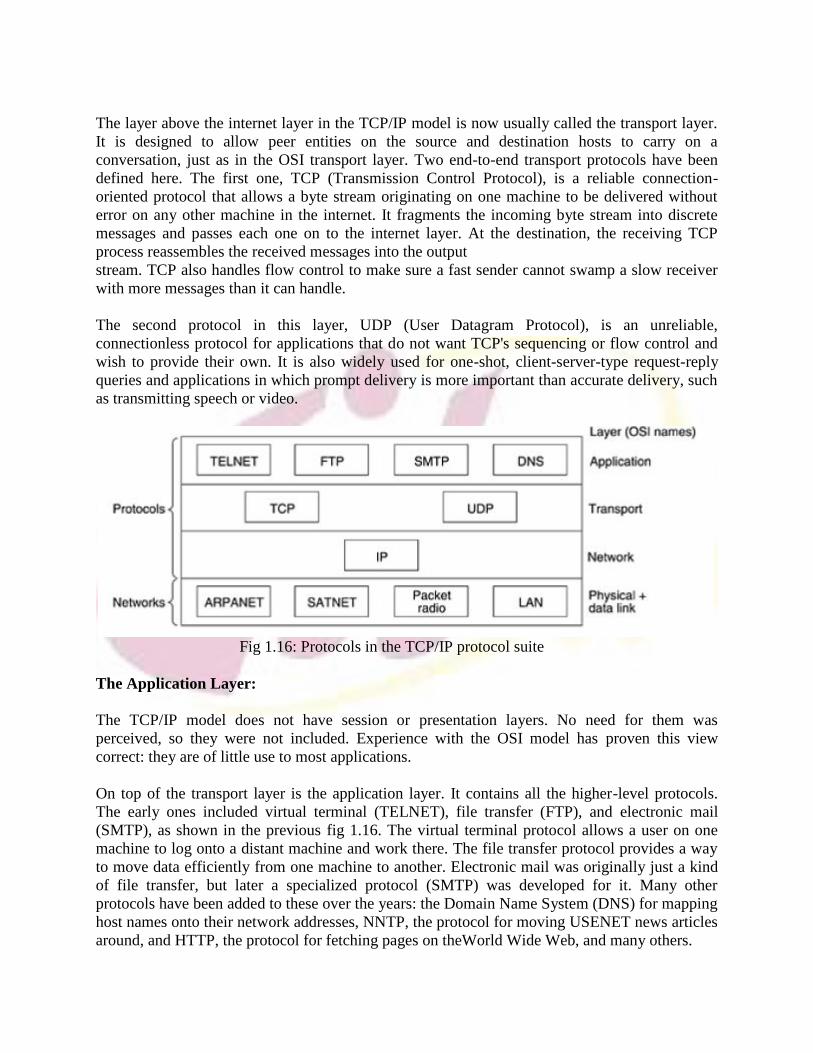
Fig 1.16: Protocols in the TCP/IP protocol suite
The Application Layer:
The TCP/IP model does not have session or presentation layers. No need for them wasperceived, so they were not included. Experience with the OSI model has proven this viewcorrect: they are of little use to most applications.
On top of the transport layer is the application layer. It contains all the higher-level protocols.The early ones included virtual terminal (TELNET), file transfer (FTP), and electronic mail(SMTP), as shown in the previous fig 1.16. The virtual terminal protocol allows a user on onemachine to log onto a distant machine and work there. The file transfer protocol provides a wayto move data efficiently from one machine to another. Electronic mail was originally just a kindof file transfer, but later a specialized protocol (SMTP) was developed for it. Many otherprotocols have been added to these over the years: the Domain Name System (DNS) for mappinghost names onto their network addresses, NNTP, the protocol for moving USENET news articlesaround, and HTTP, the protocol for fetching pages on theWorld Wide Web, and many others.

The Host-to-Network Layer:
Below the internet layer is a great void. The TCP/IP reference model does not really say muchabout what happens here, except to point out that the host has to connect to the network usingsome protocol so it can send IP packets to it. This protocol is not defined and varies from host tohost and network to network. Books and papers about the TCP/IP model rarely discuss it.
6. Example Networks
The subject of computer networking covers many different kinds of networks, large and small,well known and less well known. They have different goals, scales, and technologies. In thefollowing sections, we will look at some examples, to get an idea of the variety one finds in thearea of computer networking.
We will start with the Internet, probably the best known network, and look at its history,evolution, and technology. Then we will consider ATM, which is often used within the core oflarge (telephone) networks. Technically, it is quite different from the Internet, contrasting nicelywith it. Next we will introduce Ethernet, the dominant local area network. Finally, we will lookat IEEE 802.11, the standard for wireless LANs.
6.1 The Internet:
The Internet is a global system of interconnected computer networks that use the standardInternet protocol suite (often called TCP/IP, although not all applications use TCP) to servebillions of users worldwide. It is a network of networks that consists of millions of private,public, academic, business, and government networks, of local to global scope, that are linked bya broad array of electronic, wireless and optical networking technologies. The Internet carries anextensive range of information resources and services, such as the inter-linked hypertextdocuments of the World Wide Web (WWW) and the infrastructure to support email
6.2 ARPANET:
The story begins in the late 1950s. At the height of the Cold War, the DoD wanted a command-andcontrol network that could survive a nuclear war. At that time, all military communicationsused the public telephone network, which was considered vulnerable. The reason for this beliefcan be gleaned from fig 1.17(a) Here the black dots represent telephone switching offices, eachof which was connected to thousands of telephones. These switching offices were, in turn,connected to higher-level switching offices (toll offices), to form a national hierarchy with only asmall amount of redundancy. The vulnerability of the system was that the destruction of a fewkey toll offices could fragment the system into many isolated islands.
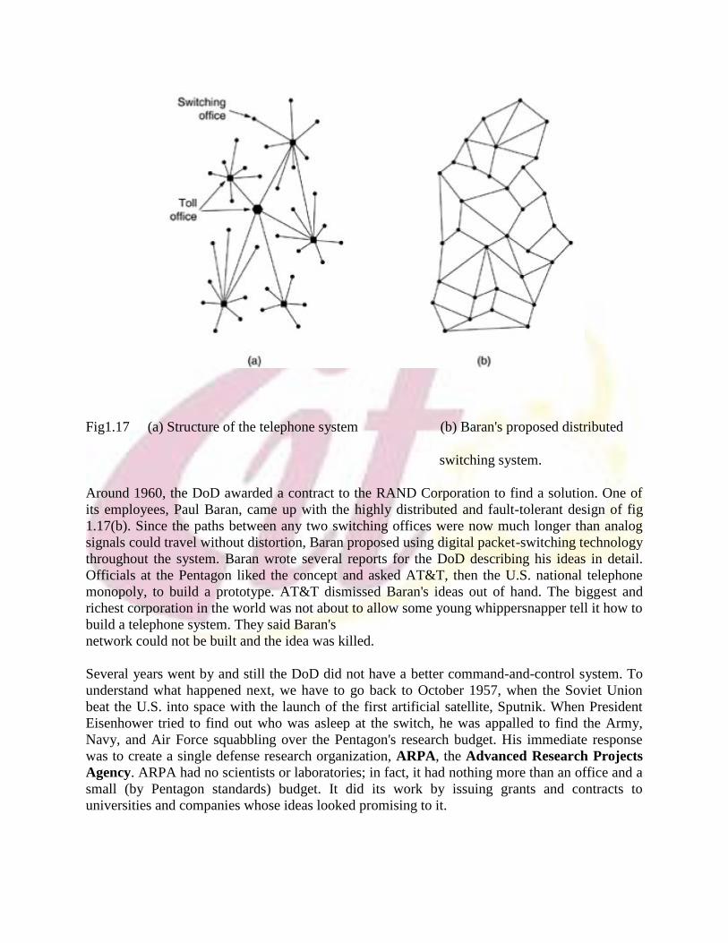
Fig1.17 (a) Structure of the telephone system (b) Baran's proposed distributed
switching system.
Around 1960, the DoD awarded a contract to the RAND Corporation to find a solution. One ofits employees, Paul Baran, came up with the highly distributed and fault-tolerant design of fig1.17(b). Since the paths between any two switching offices were now much longer than analogsignals could travel without distortion, Baran proposed using digital packet-switching technologythroughout the system. Baran wrote several reports for the DoD describing his ideas in detail.Officials at the Pentagon liked the concept and asked AT&T, then the U.S. national telephonemonopoly, to build a prototype. AT&T dismissed Baran's ideas out of hand. The biggest andrichest corporation in the world was not about to allow some young whippersnapper tell it how tobuild a telephone system. They said Baran'snetwork could not be built and the idea was killed.
Several years went by and still the DoD did not have a better command-and-control system. Tounderstand what happened next, we have to go back to October 1957, when the Soviet Unionbeat the U.S. into space with the launch of the first artificial satellite, Sputnik. When PresidentEisenhower tried to find out who was asleep at the switch, he was appalled to find the Army,Navy, and Air Force squabbling over the Pentagon's research budget. His immediate responsewas to create a single defense research organization, ARPA, the Advanced Research ProjectsAgency. ARPA had no scientists or laboratories; in fact, it had nothing more than an office and asmall (by Pentagon standards) budget. It did its work by issuing grants and contracts touniversities and companies whose ideas looked promising to it.

For the first few years, ARPA tried to figure out what its mission should be, but in 1967, theattention of ARPA's then director, Larry Roberts, turned to networking. He contacted variousexperts to decide what to do. One of them, Wesley Clark, suggested building a packet-switchedsubnet, giving each host its own router.
After some initial skepticism, Roberts bought the idea and presented a somewhat vague paperabout it at the ACM SIGOPS Symposium on Operating System Principles held in Gatlinburg,Tennessee in late 1967 (Roberts, 1967). Much to Roberts' surprise, another paper at theconference described a similar system that had not only been designed but actually implementedunder the direction of Donald Davies at the National Physical Laboratory in England. The NPLsystem was not a national system (it just connected several computers on the NPL campus), butit demonstrated that packet switching could be made to work. Furthermore, it cited Baran's nowdiscarded earlier work. Roberts came away fromGatlinburg determined to build what later became known as the ARPANET.
The software was split into two parts: subnet and host. The subnet software consisted of the IMPend of the host-IMP connection, the IMP-IMP protocol, and a source IMP to destination IMPprotocol designed to improve reliability. The original ARPANET design is shown in fig 1.18.
Fig 1.18: Origin of ARPANET design
Outside the subnet, software was also needed, namely, the host end of the host-IMP connection,the host-host protocol, and the application software. It soon became clear that BBN felt thatwhen it had accepted a message on a host-IMP wire and placed it on the host-IMP wire at thedestination, its job was done.
During the 1980s, additional networks, especially LANs, were connected to the ARPANET. Asthe scale increased, finding hosts became increasingly expensive, so DNS (Domain NameSystem) was created to organize machines into domains and map host names onto IP addresses.Since then, DNS has become a generalized, distributed database system for storing a variety ofinformation related to naming.

6.3 Asynchronous Transfer Mode(ATM)
Yet another, and far more important, connection-oriented network is ATM (AsynchronousTransfer Mode). The reason for the somewhat strange name is that in the telephone system,most transmission is synchronous (closely tied to a clock), and ATM is not.
ATM was designed in the early 1990s and launched amid truly incredible hype (Ginsburg, 1996;Goralski, 1995; Ibe, 1997; Kim et al., 1994; and Stallings, 2000). ATM was going to solve all theworld's networking and telecommunications problems by merging voice, data, cable television,telex, telegraph, carrier pigeon, tin cans connected by strings, tom-toms, smoke signals, andeverything else into a single integrated system that could do everything for everyone. It did nothappen. In large part, the problems were similar to those we described earlier concerning OSI,that is, bad timing, technology, implementation, and politics. Having just beaten back thetelephone companies in round 1, many in the Internet community saw ATM as Internet versusthe Telcos: the Sequel. But it really wasnot, and this time around even diehard datagram fanatics were aware that the Internet's quality ofservice left a lot to be desired. To make a long story short, ATM was much more successful thanOSI, and it is now widely used deep within the telephone system, often for moving IP packets.Because it is now mostly used by carriers for internal transport, users are often unaware of itsexistence, but it is definitely alive and well.
The ATM Reference Model
ATM has its own reference model, different from the OSI model and also different from theTCP/IP model. This model is shown in Fig. 1.19. It consists of three layers, the physical, ATM,and ATM adaptation layers, plus whatever users want to put on top of that.
Fig 1.19: ATM Reference model
The physical layer deals with the physical medium: voltages, bit timing, and various otherissues. ATM does not prescribe a particular set of rules but instead says that ATM cells can besent on a wire or fiber by themselves, but they can also be packaged inside the payload of othercarrier systems. In other words, ATM has been designed to be independent of the transmissionmedium.

The ATM layer deals with cells and cell transport. It defines the layout of a cell and tells whatthe header fields mean. It also deals with establishment and release of virtual circuits. Congestioncontrol is also located here.
Because most applications do not want to work directly with cells (although some may), a layerabove the ATM layer has been defined to allow users to send packets larger than a cell. TheATM interface segments these packets, transmits the cells individually, and reassembles them atthe other end. This layer is the AAL (ATM Adaptation Layer).
Unlike the earlier two-dimensional reference models, the ATM model is defined as beingthreedimensional, as shown in Fig. 1.19. The user plane deals with data transport, flow control,error correction, and other user functions. In contrast, the control plane is concerned withconnection management. The layer and plane management functions relate to resourcemanagement and interlayer coordination.
6.4 Ethernet
Both the Internet and ATM were designed for wide area networking. However, many companies,universities, and other organizations have large numbers of computers that must be connected.This need gave rise to the local area network. In this section we will say a little bit about themost popular LAN, Ethernet.
The story starts out in pristine Hawaii in the early 1970s. In this case, ''pristine'' can beinterpreted as ''not having a working telephone system.'' While not being interrupted by thephone all day long makes life more pleasant for vacationers, it did not make life more pleasantfor researcher Norman Abramson and his colleagues at the University of Hawaii who were tryingto connect users on remote islands to the main computer in Honolulu. Stringing their own cablesunder the Pacific Ocean was not in the cards, so they looked for a different solution.
The one they found was short-range radios. Each user terminal was equipped with a small radiohaving two frequencies: upstream (to the central computer) and downstream (from the centralcomputer). When the user wanted to contact the computer, it just transmitted a packet containingthe data in the upstream channel. If no one else was transmitting at that instant, the packetprobably got through and was acknowledged on the downstream channel. If there was contentionfor the upstream channel, the terminal noticed the lack of acknowledgement and tried again.Since there was only one sender on the downstream channel (the central computer), there werenever collisions there. This system, calledALOHANET, worked fairly well under conditions of low traffic but bogged down badly whenthe upstream traffic was heavy.
About the same time, a student named Bob Metcalfe got his bachelor's degree at M.I.T. and thenmoved up the river to get his Ph.D. at Harvard. During his studies, he was exposed toAbramson's work. He became so interested in it that after graduating from Harvard, he decidedto spend the summer in Hawaii working with Abramson before starting work at Xerox PARC(Palo Alto Research Center). When he got to PARC, he saw that the researchers there had

designed and built what would later be called personal computers. But the machines wereisolated. Using his knowledge of Abramson's work, he, together with his colleague David Boggs,designed and implemented the first local area network (Metcalfe and Boggs, 1976).
They called the system Ethernet after the luminiferous ether, through which electromagneticradiation was once thought to propagate. (When the 19th century British physicist James ClerkMaxwell discovered that electromagnetic radiation could be described by a wave equation,scientists assumed that space must be filled with some ethereal medium in which the radiationwas propagating. Only after the famous Michelson-Morley experiment in 1887 did physicistsdiscover that electromagnetic radiation could propagate in a vacuum.)
Fig 1.20: Original Ethernet structure
6.5 Wireless LANs: 802.11:
Almost as soon as notebook computers appeared, many people had a dream of walking into anoffice and magically having their notebook computer be connected to the Internet. Consequently,various groups began working on ways to accomplish this goal. The most practical approach is toequip both the office and the notebook computers with short-range radio transmitters andreceivers to allow them to communicate. This work rapidly led to wireless LANs being marketedby a variety of companies. The trouble was that no two of them were compatible. Thisproliferation of standards meant that a computer equipped with a brand X radio would not workin a room equipped with a brand Y base station. Finally, the industry decided that a wireless LANstandard might be a good idea, so the IEEE committee that standardized the wired LANs wasgiven the task of drawing up a wireless LAN standard.The standard it came up with was named 802.11. A common slang name for it is WiFi. It is animportant standard and deserves respect, so we will call it by its proper name, 802.11.
Wireless networking with base station and with Adhoc networks:
Fig 1.21 (a) Wireless networking with base (b) Ad-hoc networks


![Unit 1 Unit 2 Unit 3 Unit 4 Unit 5 Unit 6 Unit 7 Unit 8 ... 5 - Formatted.pdf · Unit 1 Unit 2 Unit 3 Unit 4 Unit 5 Unit 6 ... and Scatterplots] Unit 5 – Inequalities and Scatterplots](https://img.pdfslide.us/doc/110x75/5b76ea0a7f8b9a4c438c05a9/unit-1-unit-2-unit-3-unit-4-unit-5-unit-6-unit-7-unit-8-5-formattedpdf.jpg)