Embed Size (px)
Citation preview
Tutorial Third Peg Transfer Exercise
School of Electrical Engineering & Computer Science,National University of Sciences & Technology, Pakistan 1
What’s new
• Practice of Rigid Mechanical Object.
• A proper interactive exercise making practice to train some one.
Scene
Now what we want to build right now is
• Some static bars placed on a static tray enclosed in a static cubical box which is opened from one side.
• Along with Two pegs one Rigid and one Deformable placed in the box.
• A practitioner will have to put those pegs in one bar and then transfer t to the other bar by pick and place it up in another bar.
Adding nodes
• First of all add four nodes to the Root Node and name them
1. Peg Box.
2. Peg Tray.
3. Bars.
4. Peg Deformable.
• Now add the collision and Visual Nodes to them.
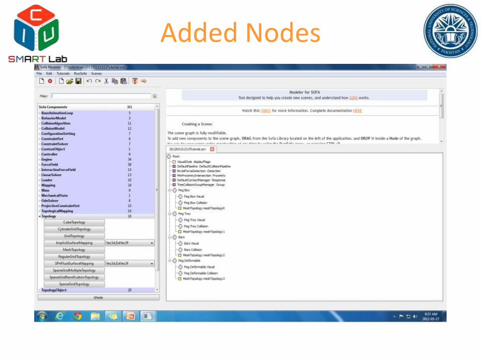
Added Nodes
MeshTopology
• Now Add Mesh topology to all.
• In every node’s meshtopology component, add following object file’s location in the fileTopologyblank of property 1/3,in respect to there name.1. pegbox.obj (attached with this exercise) for Peg Box node’s
Mestopology Object.
2. pegtray.obj (attached with this exercise) for Peg Tray node’s Mestopology Object.
3. bars.obj (attached with this exercise) for Bars node’s Mestopology Object.
4. torus.obj (attached with this exercise) for Peg Deformable node’s Mestopology Object.
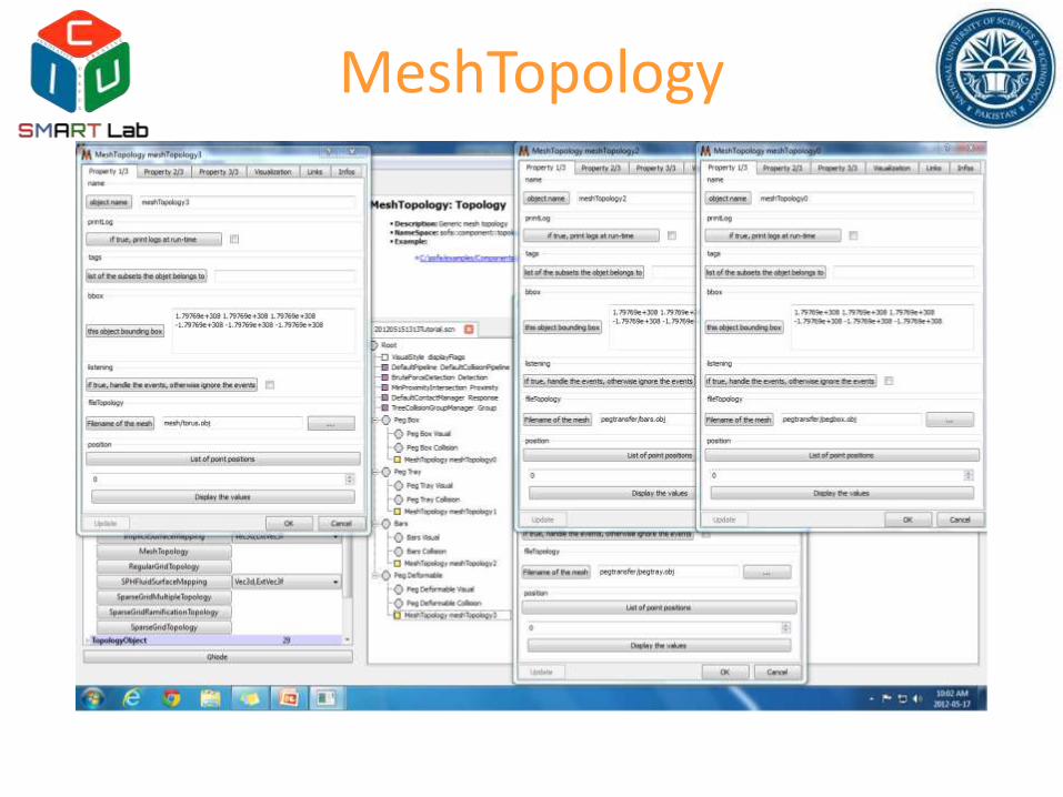
MeshTopology
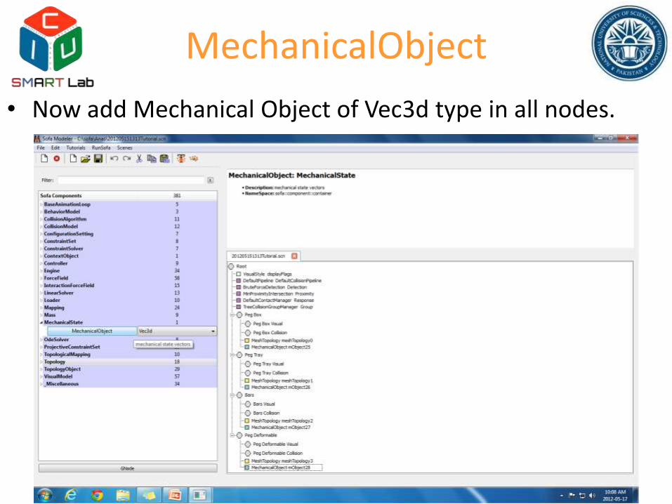
MechanicalObject
• Now add Mechanical Object of Vec3d type in all nodes.
Collision Model
• Now we will have to add the collision models in all of the collision nodes of the object nodes.
– For this we will drag and drop Ttriangle model in all of the collision nodes other than Peg deformable.
– In Peg deformable we will add Tsphere model in the collision nodes of the Peg-Deformable
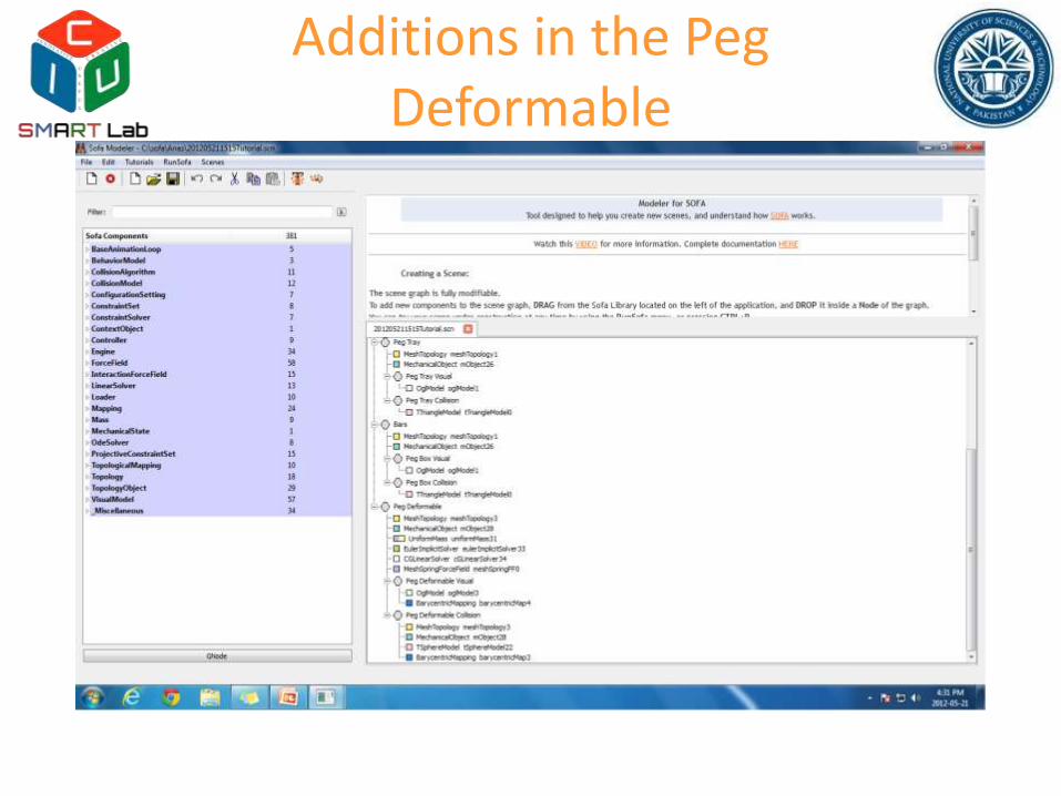
Additions in the PegDeformable
• As we want our peg to feel all of the forces and deform and displace accordingly.
• We will have to add some other properties differing from the other nodes like mass, ODE & Linear solver along with some Force Field in Peg Deformable.
• In our current exercise the user will handle and move the peg on his will, so we will have to assign a separate mestopolgy and the mechanical object to the collision node.
• To map the Graphical and Collision nodes on the parent node’s objects we will add Barycentric mapping in both of them.
Additions in the PegDeformable
Peg Rigid
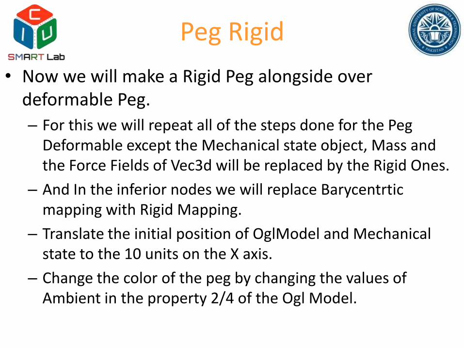
• Now we will make a Rigid Peg alongside over deformable Peg.
– For this we will repeat all of the steps done for the Peg Deformable except the Mechanical state object, Mass and the Force Fields of Vec3d will be replaced by the Rigid Ones.
– And In the inferior nodes we will replace Barycentrticmapping with Rigid Mapping.
– Translate the initial position of OglModel and Mechanical state to the 10 units on the X axis.
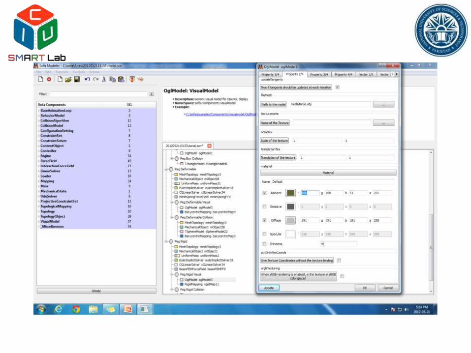
– Change the color of the peg by changing the values of Ambient in the property 2/4 of the Ogl Model.
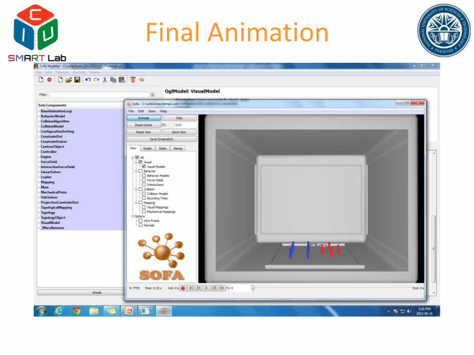
Resultant Animated Exercise
• Now Animate the scene, there you will see two pegs side by side
1. Deformable Vec3d.
2. Non-Deformable Rigid.
• To practice pick one peg by simultaneous clicking the Left and pressing shift key on them and place them in one desired bar.
Final Animation
![TUTORIAL: BASIC OPERATIONS [1] AN EXERCISE ON HOW …miniahn/ecn726/gauss_basics.pdf · TUTORIAL: BASIC OPERATIONS [1] AN EXERCISE ON HOW TO USE GAUSS • On your computer, create](https://img.pdfslide.us/doc/110x75/5c4a83d893f3c34aee5376a3/tutorial-basic-operations-1-an-exercise-on-how-miniahnecn726gaussbasicspdf.jpg)